

Page 1

3G Mobile Communication cdma2000 System – All-IP Architecture
ZXC10 BTSB I1 (V1.0)
cdma2000 Base Transceiver Station
Installation Manual
ZTE CORPORATION
Page 2

ZXC10 BTSB I1(V1.0)
cdma2000 Base Transceiver Station
Installation Manual
Manual Version 20040615-R1.1
Product Version V1.0
Copyright © 2003 ZTE Corporation
All rights reserved.
No part of this documentation may be excerpted, reproduced, translated, annotated or
duplicated, in any form or by any means without the prior written permission of ZTE
Corporation.
ZTE CORPORATION
ZTE Plaza, Keji Road South, Hi-Tech Industrial Park, Nanshan District, Shenzhen, P.R.China
Website: http://www.zte.com.cn
Postcode: 518057
Customer Support Center: (+86755) 26771900 800-9830-9830
Fax: (+86755) 26770801
Email: support@zte.com.cn
* * * *
S.N.: sjzl20041524
Page 3
FAX: 0086-755-26770160
Suggestions and Feedback
To improve the quality of ZTE product documentation and offer better services to our
customers, we hope you can give us your suggestions and comments on our
documentation and fax this form to +86-755-26770160; or mail to “Marketing center
rd
floor ZTE Plaza, Keji Road South, Hi-Tech Industrial Park, Nanshan District,
3
Shenzhen, P. R. China”. Our postcode is 518057.
Document name
Product version
Equipment installation time
Your information
Name
Postcode
Telephone
Your evaluation
of this
documentation
Presentation: How is information presented? (Introductions, procedures, illustrations, others)
Good Fair Average Poor Bad
Accessibility: Can you find the information you want? (Table of contents, Index, headings,
numbering, others)
Good Fair Average Poor Bad
Intelligibility: Can you understand it when you find it? (Language, vocabulary, readability, others)
Good Fair Average Poor Bad
Presentation:
V1.0
ZXC10 BTSB (V1.0) cdma2000 Base Transceiver Station
Installation Manual
Document version 20040615-R1.1
Company
Company address
E-mail
Your suggestions
for improvement
of this
documentation
Your other
suggestions on
ZTE product
documentation
Accessibility:
Intelligibility:
Page 4

Page 5

Preface
About This Manual
This manual introduces the hardware installation flow and method of the ZXC10
BTSB I1.
It is one of the manuals of the CDMA cellular mobile communication system of ZTE.
This manual is intended to provide basic installation operation guide to the engineering
staff that install the ZXC10 BTSB I1 of ZTE. Operation and maintenance staff of the
equipment can also use it as reference.
Standardized hardware installation is the basis for the normal and stable operation of
the BS and is thus important in the project engineering. To guide the hardware
installation of ZXC10 BTSB I1, this manual is arranged in the order of engineering
installation. This manual first briefs the equipment composition, which enables the
engineering staff to have an overall understanding of the ZXC10 BTSB I1 of ZTE.
Then it details the installation flow of the equipment and the installation check.
How to Use This Manual
This manual comprises 15 chapters:
Chapter 1 Installation Overview briefs the equipment installation and commissioning
flow, the hardware installation flow and the hardware installation precautions for the
BTSB system.
Chapter 2 Installation Preparations introduces the preparations prior to the BTSB
installation, including installation environment check, and preparation for tools,
instruments and technical documentation.
Chapter 3 Unpacking and Acceptance describes unpacking, acceptance and handover
of the goods.
Chapter 4 Cabinet Installation describes the installation of the BTSB cabinet, and the
layout, connection and fixing of multiple cabinets.
Chapter 5 Power System Installation describes the installation procedure of the
BTSB power system.
Page 6

Chapter 6 Grounding System Installation describes the installation procedure of the
BTSB grounding system.
Chapter 7 Cable Installation in Cabinet introduces the types of BTSB cabinet
internal cables, and describes the installation procedure of them.
Chapter 8 Trunk Cable Installation describes the installation procedure of the BTSB
trunk cables, and explains how to prepare the E1 cables and how to convert the 75 Ω
trunk cables into the 120 Ω trunk cables.
Chapter 9 Monitoring System Installation introduces the composition of the
monitoring system and describes its installation procedure.
Chapter 10 Main Antenna Feeder System Installation describes the installation
preparation, the installation flow and the specific installation procedure of the main
antenna feeder system, and explains how to check and test the antenna feeder and how
to conduct waterproof treatment on the connector.
Conventions
Chapter 11 GPS Antenna Feeder System Installation describes the installation
preparation, the installation flow and the specific installation procedure of the GPS
antenna feeder system.
Chapter 12 Board Installation describes the types and functions of boards used in the
BTSB system, and how to install and replace them.
Chapter 13 Hardware Installation Check describes the hardware installation check
requirements of the BTSB system.
Chapter 14 Power-on/Power-off describes the check prior to the BTSB power-on, and
the detailed power-on and power-off operation procedures.
Appendix A - Appendix D gives supplementary information on the BTSB technical
performance indices and board indicators, and an abbreviation form.
Describing notational conventions, keyboard operation convention, mouse operation
convention and four safety signs.
1. Notational conventions
Angular brackets "<and>" identify names of keys and buttons, and the
information typed by an operator from a terminal. Square brackets "[and]"
Page 7
indicate a man-machine interface, menu item, data list, or field name. The
symbol "-->" separates a multi-level menu, e.g., [File --> New --> Folder]
indicates the [Folder] menu item under the [New] submenu of the menu [File].
2. Keyboard operation conventions
Format Description
Character within angular
brackets
<key 1+key 2>
<key 1, key 2>
Indicating a key or button name, e.g., <Enter>, <Tab>,
<Backspace>, and <a>
Indicating to hold several keys down at the same time. For
example, <Ctrl+Alt+A> indicates to hold down “Ctrl”, “Alt”
and “A” three keys
Press Key 1 first. Then release Key 1 and press Key 2. For
example, <Alt, F> indicates to press and release <Alt> key, and
then press <F> key
3. Mouse operation conventions
Format Description
Click Refers to clicking the primary mouse button (usually the left
mouse button) once
Double-click Refers to quickly clicking the primary mouse button (usually the
left mouse button) twice
Right-click Refers to clicking the secondary mouse button (usually the right
mouse button) once
Drag Refers to pressing and holding a mouse button and move the
mouse
4. Signs
Four eye-catching signs are used in this manual to emphasize important and
critical information.
Note, Caution, Warning, and Danger: Used to
indicate the precautions during the operation.
Statement: The actual product may differ from what is described in this
manual due to frequent update of ZTE products and fast development of
technologies. Please contact the local ZTE office for the latest updating
information of the product.
Page 8

FCC & IC STATEMENT
Before using this product, read this important RF energy awareness and control information and operational
instructions to ensure compliance with the FCC and IC RF exposure guidelines.
NOTICE: Working with the equipment while in operation, may expose the technician to RF
electromagnetic fields that exceed FCC rules for human exposure. Visit the FCC website at
www.fcc.gov/oet/rfsafety
Changes or modifications to this unit not expressly approved by the party responsible for compliance will
void the user’s authority to operate the equipment. Any change to the equipment will void FCC and IC
grant.
This equipment has been tested and found to comply with the limits for a Class A digital device, pursuant
to the FCC and IC Rules. This equipment generates, uses and can radiate radio frequency energy and, if not
installed and used in accordance with the instructions, may cause harmful interference to radio
communications. However, there is no guarantee that interference will not occur in a particular installation.
For OUTDOOR use, a PNALE Antenna with a maximum gain of 17dBi is authorized for use with this unit.
Outside antennas must be positioned to observe minimum separation of 3.0M (9.84 feet.) for 800MHz unit
and 2.5M (8.2 feet.) for 1900MHz unit from all users and bystanders. For the protection of personnel
working in the vicinity of outside (uplink) antennas, the following guidelines for minimum distances
between the human body and the antenna must be observed.
to learn more about the effects of exposure to RF electromagnetic fields.
The installation of an OUTDOOR antenna must be such that, under normal conditions, all personnel cannot
come within 3.0M (9.84 feet.)for 800MHz unit and 2.5M (8.2 feet.) for 1900MHz unit from the outside
antenna. Exceeding this minimum separation will ensure that the worker or bystander does not receive
RF-exposure beyond the Maximum Permissible Exposure according to section 1.1310 i.e. limits for
Controlled Exposure.
Page 9

Contents
1 Installation Overview..............................................................................................................................1-1
1.1 BTSB Installation Overview.......................................................................................................... 1-1
1.2 BTSB Installation Flow Chart........................................................................................................ 1-3
1.3 BTSB Precautions for Hardware Installation.................................................................................1-6
2 Installation Preparations........................................................................................................................ 2-1
2.1 Checking the Installation Environment.......................................................................................... 2-1
2.1.1 Checking the Equipment Room .......................................................................................... 2-1
2.1.2 Checking the Indoor Environment of the Equipment Room...............................................2-2
2.1.3 Checking the Power Supply System ...................................................................................2-3
2.1.4 Checking the Grounding System.........................................................................................2-5
2.1.5 Checking the Outdoor Installation Environment for the Antenna Feeder System ..............2-6
2.1.6 Checking the Safety Conditions..........................................................................................2-7
2.1.7 Checking Other Auxiliary Equipment.................................................................................2-7
2.2 Preparing Tools and Instruments.................................................................................................... 2-7
2.3 Preparing Technical Documentation ..............................................................................................2-9
3 Unpacking and Acceptance .................................................................................................................... 3-1
3.1 Checking Goods against the Packing List......................................................................................3-1
3.2 Unpacking the Wooden Box...........................................................................................................3-2
3.2.1 Wooden Box Structure ........................................................................................................3-2
3.2.2 Unpacking Procedure.......................................................................................................... 3-2
3.2.3 Checking the Rack Appearance...........................................................................................3-2
3.3 Unpacking the Carton ....................................................................................................................3-3
3.3.1 Carton..................................................................................................................................3-3
-i-
Page 10

3.3.2 Unpacking Procedure.......................................................................................................... 3-4
3.3.3 Checking the Boards........................................................................................................... 3-4
3.4 Goods Acceptance and Handover.................................................................................................. 3-4
4 Cabinet Installation ................................................................................................................................ 4-1
4.1 Cabinet Types ................................................................................................................................ 4-1
4.2 RFS Cabinet Installation................................................................................................................ 4-2
4.2.1 RFS Installation Flow ......................................................................................................... 4-2
4.2.2 Support Installation Mode .................................................................................................. 4-3
4.2.3 Base Installation Mode ....................................................................................................... 4-9
4.2.4 Cabinet Stacking Mode..................................................................................................... 4-14
4.2.5 Installing Cabinet Accessories.......................................................................................... 4-17
4.2.6 Cabinet Installation Specifications ................................................................................... 4-20
5 Power Supply System Installation......................................................................................................... 5-1
5.1 Introduction to Power Cables ........................................................................................................ 5-1
5.2 Installation Flow of Power Cables................................................................................................. 5-2
5.3 Cable Installation Procedure.......................................................................................................... 5-2
6 Grounding System Installation.............................................................................................................. 6-1
6.1 Grounding System Overview ........................................................................................................ 6-1
6.2 Installing the Grounding System ................................................................................................... 6-3
6.2.1 Installing the Outdoor Grounding Copper Bar ................................................................... 6-3
6.2.2 Installing the Feeder Grounding Clip ................................................................................. 6-3
6.2.3 Installing the Indoor Lightning Arrester ............................................................................. 6-6
7 Cable Installation in Cabinet................................................................................................................. 7-1
7.1 BTSB Cable Installation Overview ............................................................................................... 7-1
7.2 Installing Cables in the BDS Cabinet ............................................................................................ 7-2
7.2.1 BDS Cable Types................................................................................................................ 7-2
-ii-
Page 11

7.2.2 Installing Power Cables in the BDS....................................................................................7-2
7.2.3 Installing Optical Fibers...................................................................................................... 7-2
7.2.4 Installing Monitoring Cables in the BDS............................................................................7-3
7.2.5 Internal Cabling Table of the BDS......................................................................................7-3
7.2.6 Internal Cabling of the BDS................................................................................................ 7-5
7.3 RFS Installing Cables in the RFS Cabinet ..................................................................................... 7-6
7.3.1 Installing Power Cables.......................................................................................................7-6
7.3.2 Installation Interconnection Signal Cables.......................................................................... 7-8
7.3.3 Installing Monitoring Cables...............................................................................................7-9
7.3.4 Installing RF Cables..........................................................................................................7-12
7.3.5 Connecting Optical Fibers................................................................................................. 7-16
7.4 Types and Installation of Inter-Cabinet Cables ............................................................................7-17
7.4.1 Installing BDS-RFS Interconnection Cable......................................................................7-17
7.4.2 Installing Optical Fibers.................................................................................................... 7-18
7.4.3 Installing Interconnection Cables with BPWS.................................................................. 7-18
8 Trunk Cable Installation ........................................................................................................................8-1
8.1 Installing E1 Cables ....................................................................................................................... 8-1
8.2 Making E1 Cables..........................................................................................................................8-4
8.3 Converting 75 Ω Trunk Cable to 120 Ω Trunk Cable.................................................................... 8-7
8.3.1 Appearance of the Impedance Converter ............................................................................ 8-8
8.3.2 Wiring of the Impedance Converter.................................................................................... 8-8
8.3.3 Technical Parameters of the Impedance Converter .............................................................8-9
9 Monitoring System Installation .............................................................................................................9-1
9.1 Composition of the Monitoring System......................................................................................... 9-1
9.2 Installing the Monitoring System...................................................................................................9-2
9.2.1 Installing the Indoor Smog Sensor...................................................................................... 9-2
-iii-
Page 12

9.2.2 Installing the Indoor Temperature/Humidity Sensor........................................................... 9-3
9.2.3 Installing the Infrared Sensor.............................................................................................. 9-4
10 Main Antenna Feeder System Installation ....................................................................................... 10-1
10.1 Preparation for Installing the Antenna Feeder System .............................................................. 10-1
10.1.1 Preparation by Installation Personnel ............................................................................. 10-2
10.1.2 Checking the Installation Environment .......................................................................... 10-2
10.1.3 Checking the Safety Measures........................................................................................ 10-3
10.1.4 Preparing Installation Tools............................................................................................ 10-4
10.2 Structure of the Antenna Feeder System.................................................................................... 10-4
10.3 Installation Content and Flow.................................................................................................... 10-6
10.3.1 Technical Parameters for Antenna Installation ............................................................... 10-6
10.3.2 Antenna Installation Flow............................................................................................... 10-7
10.4 Installing the Parts ..................................................................................................................... 10-8
10.4.1 Determining the Antenna Installation Position............................................................... 10-8
10.4.2 Moving and Hoisting the Antenna .................................................................................. 10-8
10.4.3 Installing and Adjusting the Directional Antenna........................................................... 10-9
10.4.4 Installing and Adjusting the Omni-antenna .................................................................. 10-12
10.4.5 Sealing the Connection between Jumper and Antenna ................................................. 10-12
10.4.6 Installing the Feeder Window ....................................................................................... 10-13
10.4.7 Installing the Feeders.................................................................................................... 10-14
10.4.8 Installing the Indoor Jumpers ....................................................................................... 10-25
10.5 Checking and Testing the Installation of the Antenna Feeder Part .......................................... 10-25
10.5.1 Lightning Protection for the Outdoor Antenna ............................................................. 10-25
10.5.2 Testing the Antenna SWR............................................................................................. 10-26
10.6 Waterproof Treatment for the Connectors ............................................................................... 10-26
11 GPS Antenna Feeder System Installation..........................................................................................11-1
-iv-
Page 13

11.1 Preparation for Installing the Antenna Feeder System ............................................................... 11-1
11.2 Structure of the Antenna Feeder System .................................................................................... 11-1
11.3 Installation Flow.........................................................................................................................11-2
11.4 Installing the Parts...................................................................................................................... 11-2
11.4.1 Preparing the GPS Coaxial Cable Connectors ................................................................11-2
11.4.2 Installing the Lightning Arrester .....................................................................................11-4
12 Board Installation ...............................................................................................................................12-1
12.1 BTSB Board Types.....................................................................................................................12-1
12.2 RF Cabinet Boards .....................................................................................................................12-2
12.2.1 Receiver Front End (RFE)...............................................................................................12-2
12.2.2 Power Amplifier (PA)......................................................................................................12-3
12.2.3 Transceiver (TRX) ..........................................................................................................12-4
12.3 Cabinet Front Boards .................................................................................................................12-5
12.3.1 Board Overview ..............................................................................................................12-5
12.3.2 Installing and Replacing the Boards................................................................................12-6
12.4 Interface Boards at the Back of the Baseband Cabinet ..............................................................12-7
12.4.1 Interface Board Overview............................................................................................... 12-7
12.4.2 Interface Board Diagram................................................................................................. 12-9
12.4.3 Interface Board Structure ..............................................................................................12-10
12.4.4 Installing and Replacing the Interface Boards ..............................................................12-10
12.5 Board Installation Sequence.....................................................................................................12-10
13 Hardware Installation Check............................................................................................................. 13-1
13.1 Checking the Cabinet................................................................................................................. 13-1
13.2 Checking the Cable Racks .........................................................................................................13-2
13.3 Checking Cable Laying, Binding and Identifying......................................................................13-2
13.4 Checking the Power Cables and Grounding Cables...................................................................13-3
-v-
Page 14

13.5 Checking the E1 Cables............................................................................................................. 13-5
13.6 Checking the Sensors................................................................................................................. 13-5
13.7 Checking the Internal Connections of the Cabinet .................................................................... 13-6
13.8 Checking Indoor 1/2" Jumpers .................................................................................................. 13-6
13.9 Checking the Lightning Arrester................................................................................................ 13-6
13.10 Checking the Lightning Arrester Rack .................................................................................... 13-7
13.11 Checking the Primary Feeder Cables and GPS Feeder Cables ................................................ 13-7
13.12 Checking the Feeder Cable Window and Water-Blocking Curve of the Primary Feeder Cable
........................................................................................................................................................... 13-9
13.13 Checking the Three-Way Feeder Cards ................................................................................... 13-9
13.14 Checking the Outdoor 1/2" Jumpers...................................................................................... 13-10
13.15 Checking the Antenna............................................................................................................ 13-11
13.16 Checking Feeders of SWR..................................................................................................... 13-14
13.17 Checking Indoor & Outdoor Environments........................................................................... 13-15
13.18 Base Station Information Table.............................................................................................. 13-15
14 Power-on/Power-off ............................................................................................................................ 14-1
14.1 Checking before Power-on ........................................................................................................ 14-1
14.1.1 Checking the External Connections of the Rack ............................................................ 14-1
14.1.2 Checking the Internal of the Rack .................................................................................. 14-2
14.2 Procedure of Power-on .............................................................................................................. 14-3
14.2.1 Initial Power-on .............................................................................................................. 14-3
14.2.2 Normal Power-on............................................................................................................ 14-4
14.3 Procedure of Power-off.............................................................................................................. 14-4
14.4 Hot Swap ................................................................................................................................... 14-5
Appendix A Technical performance indices of the BTSB...................................................................... A-1
A.1 Mechanical indices ...................................................................................................................... A-1
A.2 Power indices............................................................................................................................... A-1
-vi-
Page 15

Appendix B Using SiteMaster.................................................................................................................. B-1
B.1 Selecting a frequency range.......................................................................................................... B-1
B.2 Checking SiteMaster .................................................................................................................... B-1
B.3 Inputting feeder parameters.......................................................................................................... B-2
B.4 Installing the tester ....................................................................................................................... B-2
B.5 Measuring SWR ........................................................................................................................... B-2
B.6 Measuring DTF ............................................................................................................................ B-3
Appendix C BTSB board indicators........................................................................................................ C-1
C.1 RMM indicators ........................................................................................................................... C-1
C.2 Board indicators ........................................................................................................................... C-2
Appendix D Abbreviations ...................................................................................................................... 14-1
-vii-
Page 16

Page 17

List of Figures
Fig. 1.1-1 BTSB Cabinet Composed of RF Chassis/BDS Chassis/PWS Chassis 1-2
Fig. 1.1-2 Appearance of BTSB Macro Base Station and PWS/BDS/RFS Chassis 1-2
Fig. 1.1-3 BTSB Installation Hardware 1-3
Fig. 1.2-1 Hardware Installation Flow 1-5
Fig. 3.2-1 Structure of the Wooden Box 3-2
Fig. 3.3-1 Packing Box of Modules 3-4
Fig. 4.1-1 Flexible Combination of ZXC10 BTSB I1 Subracks 4-2
Fig. 4.2-1 Cabinet Installation Flow 4-3
Fig. 4.2-2 Zoom-in Diagram of Support Fixing 4-4
Fig. 4.2-3 Support Installation Flow 4-4
Fig. 4.2-4 Position of Caster Wheels and Supports 4-5
Fig. 4.2-5 Rotating Supports Downward 4-6
Fig. 4.2-6 Positions of Installation Holes of Cabinet Supports 4-7
Fig. 4.2-7 Installing Supports and Pressure Plate 4-8
Fig. 4.2-8 Cabinet after Installation 4-9
Fig. 4.2-9 Installation on Universal Base 4-10
Fig. 4.2-10 Base Installation Flow 4-11
Fig. 4.2-11 Locations of the Installation Holes for the Four Bases 4-12
Fig. 4.2-12 Installing Pressure Plate of the Base 4-13
Fig. 4.2-13 Fixation of Supports, Pressure Plate and Base 4-14
Fig. 4.2-14 Installation of BDS Unit 4-15
Fig. 4.2-15 Installation of PWS Unit 4-16
Fig. 4.2-16 Appearance of the BDS and PWS Units after Installation 4-17
-i-
Page 18

Fig. 4.2-17 Installation of Feeder Fixing Rack 4-18
Fig. 4.2-18 Feeder Fixing Rack after Installation 4-19
Fig. 4.2-19 Installation and Replacement of Dust Filters 4-19
Fig. 5.1-1 BDS Power Cable Installation on BTSB 5-1
Fig. 5.2-1 Installation Flow of RFS Power 5-2
Fig. 5.3-1 RFS Power Cabling 5-3
Fig. 5.3-2 BDS Power Cabling 5-3
Fig. 5.3-3 Connection between Busbar and Backplane 5-4
Fig. 5.3-4 Connecting Power Cable (1) 5-5
Fig. 5.3-5 Connecting Power Cable (2) 5-6
Fig. 6.1-1 Wiring for the BTSB Grounding.............................................................................. 6-2
Fig. 6.2-1 Appearance of the Grounding Copper Bar 6-3
Fig. 6.2-2 Structure of the Grounding Clip............................................................................... 6-4
Fig. 6.2-3 Wrapping the Grounding Cable of the Grounding Clip with Waterproof Tape 6-5
Fig. 6.2-4 Installing the Lightning Arrester Frame 6-7
Fig. 7.2-1 Internal Cabling of BDS 7-5
Fig. 7.3-1 Power Cabling in RFS 7-8
Fig. 7.3-2 RFS Backplane Layout 7-10
Fig. 7.3-3 Layout of the Interface Board on the Top of RFS Cabinet 7-11
Fig. 7.3-4 Signal and Monitoring Cabling in the RFS 7-12
Fig. 7.3-5 RF Cable Interface in RFS ..................................................................................... 7-15
Fig. 7.3-6 RF Cabling in the RFS 7-16
Fig. 7.4-1 Interconnection Cables between BDS and RFS Cabinets 7-18
Fig. 8.1-1 D_SUB44-core Connector Connecting BDS 8-1
Fig. 8.1-2 Structure of 75 Ω E1 Cable 8-2
Fig. 8.1-3 Structure of 120 Ω E1 Cable.................................................................................... 8-3
-ii-
Page 19

Fig. 8.2-1 Assembly of thCC4Y-J32 Coaxial Cable Connector 8-5
Fig. 8.2-2 Coaxial Connector of the DDF 8-6
Fig. 8.2-3 Assembling DDF Coaxial Cable Plug 8-7
Fig. 8.3-1 Appearance and Wiring of an Impedance Converter 8-8
Fig. 8.3-2 Wiring of the Impedance Converter 8-9
Fig. 9.1-1 Structure of External Monitoring Cable of RFS 9-1
Fig. 9.2-1 Installing the Smog Sensor Base 9-3
Fig. 9.2-2 Installation of Temperature-Humidity Converter 9-4
Fig. 9.2-3 Location of the Infrared Sensor 9-5
Fig. 9.2-4 Structure of Infrared Sensor 9-6
Fig. 9.2-5 Structure of Infrared Sensor Cable 9-7
Fig. 10.2-1 Typical Structure of the Antenna Feeder System with Three Sectors 10-5
Fig. 10.3-1 Antenna Installation Flow 10-7
Fig. 10.4-1 Hoisting an Antenna 10-9
Fig. 10.4-2 Installing the KATHRAIN Antenna....................................................................10-11
Fig. 10.4-3 Adjusting the Pitch Angle of the Antenna 10-12
Fig. 10.4-4 Structure of the Feeder Window 10-14
Fig. 10.4-5 Structure of a BTSB Feeder 10-15
Fig. 10.4-6 Cutting Tool for the 7/8" Feeder Connector 10-16
Fig. 10.4-7 Cutting the Feeder with a Cutter 10-17
Fig. 10.4-8 Checking the Cutting Length of the Feeder 10-17
Fig. 10.4-9 Expanding the External Conductor of the Feeder with a Tube Expander 10-18
Fig. 10.4-10 Connecting the Front Part and the Back Part of the Feeder Connector 10-18
Fig. 10.4-11 Fixing the Front Part and the Back Part of the Feeder 10-19
Fig. 10.4-12 Pulling the Feeder Cable up the Iron Tower ..................................................... 10-21
Fig. 10.4-13 Three-feeder Clip 10-22
-iii-
Page 20

Fig. 10.4-14 Introducing Feeders into the Equipment Room (Method 1) 10-23
Fig. 10.4-15 Introducing Feeders into the Equipment Room (Method 2) 10-23
Fig. 10.5-1 Installation and Lightning Protection of Arrester 10-25
Fig. 10.6-1 Wrapping the Waterproof Adhesive Tapes (1) 10-27
Fig. 10.6-2 Wrapping the Waterproof Adhesive Tapes (2) 10-27
Fig. 10.6-3 Wrapping the Waterproof Adhesive Tapes (3) 10-28
Fig. 11.2-1 Composition of the GPS Antenna Feeder System 11-2
Fig. 11.4-1 Stripping GPS Cable 11-3
Fig. 11.4-2 Welding GPS Connector Pin 11-3
Fig. 11.4-3 Structure of the N-J7A Cable Connection Part 11-3
Fig. 12.3-1 Board Mechanical Structure 12-5
Fig. 12.3-2 Picture of a Board................................................................................................. 12-6
Fig. 12.3-3 Loosening the Screws and Unplugging the RFE 12-7
Fig. 12.4-1 BIM Interface Board Structure............................................................................. 12-8
Fig. 12.4-2 Structure of a Back Interface Board 12-10
Fig. 12.5-1 Positions of Boards ............................................................................................ 12-11
Fig. 13.14-1 Waterproof Outdoor 1/2” Jumper 13-11
Fig. 13.15-1 Antenna Installation Checking the Feeder SWR 13-14
Fig. B.5-1 SWR Test for the Antenna Feeder B-3
Fig. B.6-1 Antenna Feeder DTF Measurement B-4
Fig. C.1-1 Indicators on the RMM C-1
-iv-
Page 21

List of Tables
Table 2.1-1 DC Power Supply Indices for the Normal Operation of BTSB .....................................2-4
Table 2.1-2 Power Consumption Indices for the Normal Operation of BTSB.................................. 2-4
Table 2.2-1 Tools...............................................................................................................................2-7
Table 2.2-2 Instruments.....................................................................................................................2-9
Table 7.2-1 Internal Cabling Table of BDS....................................................................................... 7-3
Table 7.2-2 Internal Optical Fiber Cabling of BDS ..........................................................................7-4
Table 7.3-1 Connection Relationship of RFS Power Cables............................................................. 7-6
Table 7.3-2 Interconnection Signal Cabling in RFS Cabinet..........................................................7-9
Table 7.3-3 Monitoring Cabling in RFS Cabinet .............................................................................. 7-9
Table 7.3-4 RF Cable Connection in the RFS Cabine..................................................................... 7-13
Table 7.3-5 Optical Fiber Connection Table in RFS Cabinet..........................................................7-17
Table 7.4-1 Optical Fiber Connection between BDS and RFS .......................................................7-18
Table 7.4-2 Signal Connection Relationships of the Interconnecting Cable with BPWS............... 7-19
Table 8.1-1 Internal Connection Relationship of a 75 Ω E1 Cable................................................... 8-2
Table 8.1-2 Internal Connection Relationship of the 120 Ω E1 Cable..............................................8-3
Table 8.1-3 Correspondence between Cable Pairs at End B and Signals..........................................8-4
Table 8.3-1 Wiring Correspondence of the Impedance Converter .................................................... 8-9
Table 9.1-1 Content of Labels Placed on the Connectors ................................................................. 9-1
Table 9.2-1 Terminal Connection of the Smog Sensor Cable Connector..........................................9-3
Table 9.2-2 Terminal Connection of the Temperature/Humidity Sensor Cable Connector...............9-4
Table 12.4-1 BIM Interface Board Interfaces .................................................................................12-8
Table A.1-1 Weight of the Integrated Machine ................................................................................A-1
Table A.2-1 BTS Power Consumption Indices in Normal Operation .............................................. A-2
-i-
Page 22

Table C.2-1 BTSB Board Indicators.................................................................................................C-2
-ii-
Page 23

1 Installation Overview
Summary:
z Hardware installation flow of the BTSB system
z Precautions for BTSB installation
1.1 BTSB Installation Overview
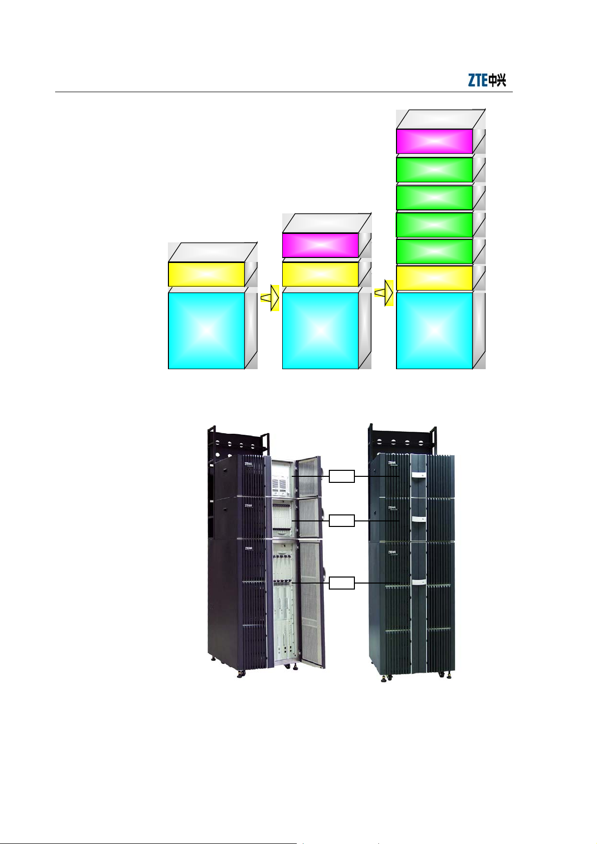
The cabinet of ZXC10 BTSB I1 comprises three basic chassis: RF chassis (RFS),
baseband chassis (BDS) and power chassis (PWS). These chassis can be combined in
different ways in a cabinet, as shown in Fig. 1.1-1. The appearance of the BTSB macro
base station of ZTE is shown in Fig. 1.1-2.
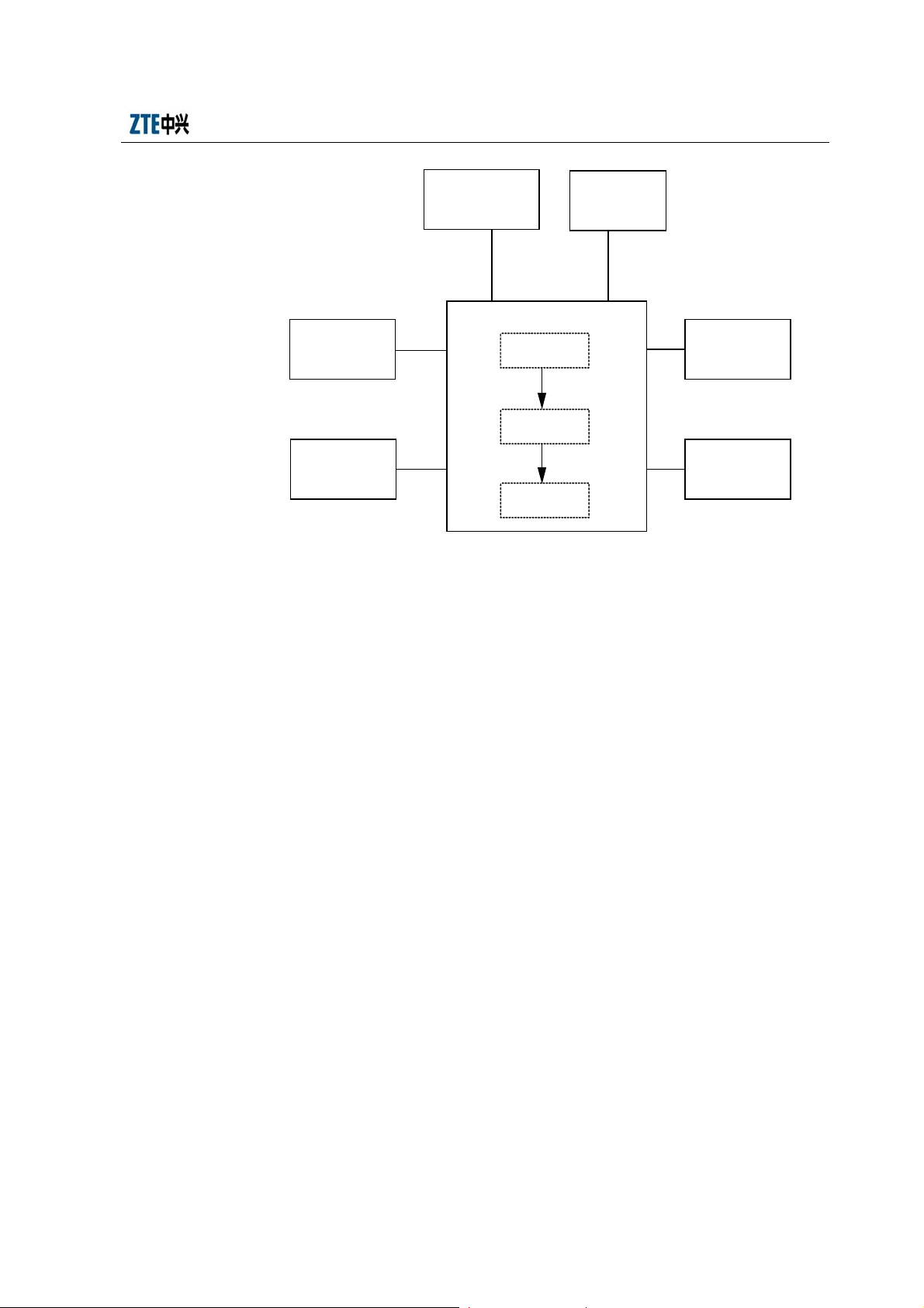
The BTSB system installation involves the following parts:
1. The BTSB cabinet, including the cabinet, internal cables and boards.
2. The power system, which provides -48V operating power for the system.
3. The grounding system, which provides protection ground for the parts of the
BTSB.
4. The antenna system, including the antenna, jumpers and feeders (a test of the
antenna & feeder system is necessary).
5. The GPS system, including the GPS and the feeder.
6. The trunk cable, that is, connecting the cables with the connectors.
7. The monitoring system, including the temperature, humidity and other
environment sensors.
BTSB system installation is shown in Fig. 1.1-3.
1-1
Page 24
ZXC10 BTSB (V1.0) cdma2000 Base Transceiver Station Installation Manual
Power chassis
Slave baseband
chassis
Slave baseband
chassis
Slave baseband
chassis
Power chassis
Slave baseband
chassis
Master baseband
chassis
Master baseband
chassis
Master baseband
chassis
RF chassis
Fig. 1.1-1 BTSB Cabinet Composed of RF Chassis/BDS Chassis/PWS Chassis
RF chassis
PWS
BDS
RFS
RF chassis
Fig. 1.1-2 Appearance of BTSB Macro Base Station and PWS/BDS/RFS Chassis
1-2
Page 25
Chapter 1 Installation Overview
GPS installation
Power supply
system installation
Grounding system
installation
Fig. 1.1-3 BTSB Installation Hardware
1.2 BTSB Installation Flow Chart
Antenna system
installation
BTSB cabinet installation
Rack
installation
Internal cable
installation
Board
installation
Trunk cable
installation
Monitoring system
installation
The normal operation of ZXC10 BTSB I1 depends heavily on the quality of the
installation engineering. The equipment must be installed in a systematic and
standardized way to eliminate stability problems caused by improper installation and
improve the reliability of the system.
This manual introduces the installation of BTSB and its parts step by step in an attempt
to guide the engineering staff in their equipment installation.
The indoor installation of ZXC10 BTSB I1 includes cabinet installation and indoor
cable connection and cabling. Please strictly follow these steps for installation:
1. Fix the rack base to the rack.
2. Position the rack and score & drill to fix it.
3. Install the power cable of the cabinet.
4. Install the monitoring cables and temperature/humidity sensors of the BTSB.
5. Install and connect the trunk cable.
6. Install boards and modules in the cabinet.
7. Connect the RF cable of the cabinet.
1-3
Page 26

ZXC10 BTSB (V1.0) cdma2000 Base Transceiver Station Installation Manual
The detailed hardware installation flow of the BTSB system is shown in Fig. 1.2-1.
This manual describes the specific installation procedure by chapters according to this
flow.
1-4
Page 27
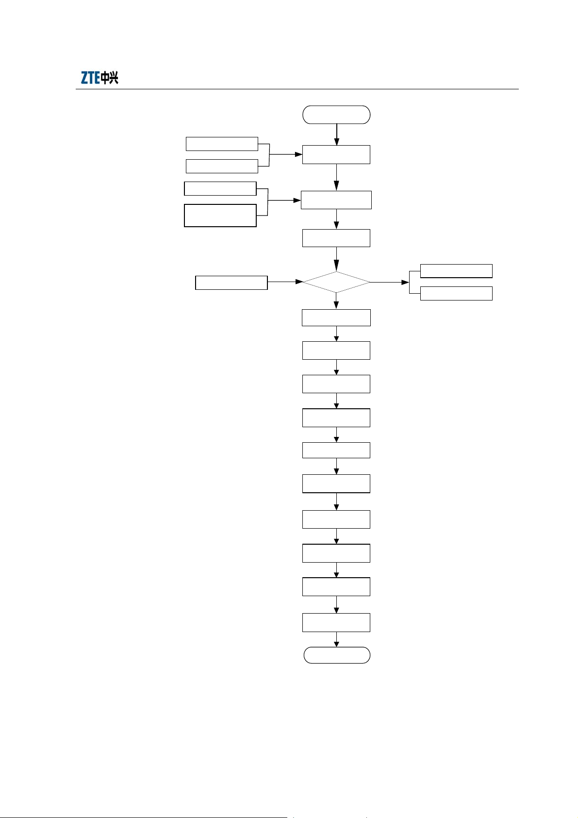
Chapter 1 Installation Overview
Start
Survey report
Engineering design file
Environment acceptance
report
Cabling rack, power supply
system, grounding system
and other accessories
Packing list
Engineering installation
preparation
Construction condition
checking
Unpacking and
acceptance
Consistence
Yes
Cabinet installation
Power supply system
installation
Grounding system
installation
Cable installation in
cabinet
Delivery error feedback
form
Replacement
application form
Trunk cable installation
Monitoring system
installation
Main antenna feeder
system installation
GPS installation
Board installation
Hardware
installation checking
End
Fig. 1.2-1 Hardware Installation Flow
1-5
Page 28

ZXC10 BTSB (V1.0) cdma2000 Base Transceiver Station Installation Manual
1.3 BTSB Precautions for Hardware Installation
Precautions for the BTSB hardware installation include:
1. Take careful precautions for the safety of yourself and the equipment during the
installation.
2. Avoid hot swap during module installation.
3. In case of lightning, never install the antenna & feeder system.
4. Before the thunderstorm season every year, check whether the lightning arrester
is in proper contact. In case any lightning arrester is damaged, replace it
immediately.
5. Lock the door right after cabinet installation.
1-6
Page 29

2 Installation Preparations
Summary:
z Environment check prior to the BTSB installation
z Tool and instrument preparation prior to the BTSB installation
z Technical documentation preparation prior to the BTSB installation
2.1 Checking the Installation Environment
Check the following environment items before installation:
Before installation, the customer should prepare the equipment room, power supply
and grounding cables, and provide necessary facilities for the project implementation.
The area and height of the equipment room should satisfy the requirements of the
equipment layout. Otherwise, reconstructions are required to eliminate the problems
faced during the installation, operation and maintenance of the equipment.
The BTSB should not be used in the environment with high temperature, thick dust,
harmful gases, explosive articles or low air pressure. It shall be put far from
transformer stations and traction substations, and shall not be in places with frequent
shaking or great noises.
As the equipment of BTSB cannot be moved easily, the equipment room construction
should be under a long-term plan.
The BTSB equipment room should comply with fire prevention regulations.
2.1.1 Checking the Equipment Room
The items for the equipment room inspection include:
1. The civil engineering of the equipment room and corridor has been completed,
and the wall is fully dry.
2. The height and width of the doors in the equipment room should not cause any
inconvenience for transporting the equipment. Usually, the height of the main
2-1
Page 30

ZXC10 BTSB (V1.0) cdma2000 Base Transceiver Station Installation Manual
doors in the equipment room should be no less than 2.2 meters, and the width
should be no less than 1 meter. The net height of the equipment room should be
no less than 3 meters. The equipment room should have a sufficient area for the
equipment with extra free space. For easy equipment operation and maintenance,
the space for opening the front door should be no less than 1 meter, and the
space at the rack rear should be no less than 0.8 meter.
3. The equipment room floor should be able to bear the weight over 450kg/m2.
4. The wall and ceiling of the equipment room should not chalk or peel off and
should be free of dust accumulation. Fire-retardant materials should be used for
decoration.
5. The shock-proof design of the equipment room should be one degree higher than
the local anti-seismic requirements. Generally, the equipment room should be
able to bear the earthquake of 7 on the Ritcher Scale. Otherwise, shock-proof
reinforcement measures must be adopted for the equipment.
6. Air-conditioning facilities should be provided to maintain desired temperature
and humidity in the equipment room.
7. Lightning screen or lightning arrester should be installed for the places in the
equipment room vulnerable to the lightning. Outdoor metal pipelines should be
grounded when being led into the equipment room.
2.1.2 Checking the Indoor Environment of the Equipment Room
The inspection of the indoor equipment room environment includes the inspection of
humidity, temperature, air pressure, antistatic protection, anti-interference requirement,
air conditioning, ventilation, dust proof, rodent proof, fire protection, lighting, and
drainage facilities.
1. Requirements for the ambient temperature and humidity
Working temperature: -5 °C ~ +55 °C
Relative humidity: 15% ~ 93% RH
2. Requirements for the equipment room floor
The level difference per square meter of the floor should not be more than 2
mm.
2-2
Page 31

Chapter 2 Installation Preparations
3. Cleanness
Cleanness is related to the amount of dust and harmful gases in the air. The
equipment room should meet the following cleanness requirements:
z No explosive, conductive, magnetic or corrosive dust.
z Density of the dust whose diameter is larger than 5µm must be less than or equal
to 3*10
4
particles/m3.
z No corrosive metal or gas that is harmful to insulations, such as SO2, NH3.
z The equipment room should be always kept clean, with the doors and windows
properly sealed.
4. Lighting
The equipment room should be equipped with 3 types of lighting facilities:
Common lighting, guaranteed lighting and emergency lighting.
5. Fire-proof requirements
The paint and decoration materials in the equipment room should be fire-proof.
The cabling holes through the wall should be filled with fire-retardant materials.
Fire-fighting devices should be equipped at the appropriate positions.
2.1.3 Checking the Power Supply System
1. DC power supply requirements:
1) BTSB employs -48V DC power supply so the equipment room should be
equipped with an AC/DC power supply converter for working power supply.
The DC voltage is allowed to range from -57V to -40V.
2) To guarantee uninterrupted operation of the BTSB even in case of mains supply
failure, uninterrupted power supply facilities such as diesel engine generator
group and storage battery should be available.
3) The noise level indices of DC power voltages shall meet the technical
specifications by the former Ministry of Posts and Telecommunications.
4) The DC power supply should be provided with over-voltage/over-current
protection and indicators.
2. AC power requirements (including the AC power for construction purpose and
2-3
Page 32

ZXC10 BTSB (V1.0) cdma2000 Base Transceiver Station Installation Manual
that used for local operation & maintenance consoles)
1) Three-phase power supply: 380V, with the voltage fluctuation range of no more
than 10%, frequency fluctuation range of no more than 5%, line voltage
waveform distortion factor of less than 5%.
2) Single-phase power supply: 220V, with the voltage fluctuation range of no more
than 10%, frequency fluctuation range of no more than 5%, line voltage
waveform distortion factor of less than 5%.
3. Cabling requirements of the power supply system
Cabling of the power supply system should be correct, tidy and in good order,
and has excellent insulation and reasonable arrangement. To prevent the power
supply system from interfering with other signal lines, power cables and other
cables should be laid separately, with special cabling troughs preferred.
In addition, during the cabling of the power supply system, the cross sections of
the cable feeders and the busbars shall be able to meet the requirements for the
medium-term or long-term capacity expansion.
2.1.3.1 Power System Range
Please see Table 2.1-1 for the DC power indices for the normal operation of ZXC10
BTSB I1 (supporting 24V DC power supply).
Table 2.1-1 DC Power Supply Indices for the Normal Operation of BTSB
Item DC Voltage
Nominal value
Allowed fluctuation
2.1.3.2 Power Consumption
Power supply and power consumption: The power consumption of ZXC10 BTSB I1
refers to the overall power consumption when the operating voltage is -48V and the
output power of each power amplifier is 20W, as shown in Table 2.1-2.
-48V
-40 ~ -57V
Table 2.1-2 Power Consumption Indices for the Normal Operation of BTSB
Configuration
1-carrier 1-sector 40W/carrier -48V About 1400W About 1400W
Amplification
Output
Working
Voltage
2-4
1X Maximum Power
Consumption (W)
DO Maximum Power
Consumption (W)
Page 33

Chapter 2 Installation Preparations
Configuration
2-carrier 1-sector 40W/carrier -48V About 1400W About 1400W
3-carrier 1-sector 40W/carrier -48V About 1400W About 1400W
5-carrier 1-sector 40W/carrier -48V About 2000W About 2000W
7-carrier 1-sector 40W/carrier -48V About 2000W About 2100W
1-carrier 3-sector 40W/carrier -48V About 2500W About 2600W
2-carrier 3-sector 40W/carrier -48V About 2600W About 2600W
3-carrier 3-sector 40W/carrier -48V About 2600W About 2700W
4-carrier 3-sector 40W/carrier -48V About 2600W About 2700W
5-carrier 3-sector 40W/carrier -48V About 4400W About 4500W
7-carrier 3-sector 40W/carrier -48V About 4500W About 4600W
8-carrier 3-sector 40W/carrier -48V About 4500W About 4700W
1-carrier 6-sector 40W/carrier -48V About 4300W About 4400W
2-carrier 6 -sector 40W/carrier -48V About 4400W About 4500W
3-carrier 6-sector 40W/carrier -48V About 4500W About 4600W
4-carrier 6-sector 40W/carrier -48V About 4500W About 4700W
Amplification
Output
Working
Voltage
1X Maximum Power
Consumption (W)
2.1.4 Checking the Grounding System
DO Maximum Power
Consumption (W)
The grounding regulations and resistance requirements (including the lightning
protection requirements) are as follows:
The communication equipment should be well grounded for reliable operation. Good
grounding ensures lightning protection and interference resistance. The grounding
cables in the equipment room should be routed in a radiating or flat way. Three
independent grounding cables should be used: The protection ground of the DC power
distribution system, the work ground of the power system and the lightning protection
ground.
The equipment adopts joint grounding with the grounding resistance less than 1 Ω.
Generally, the grounding resistance of BTSB should be less than 5 Ω. The engineering
requires the grounding resistance to be the smallest possible. The magnitude of
grounding resistance is affected by grounding post resistance, leading wire resistance,
contact resistance between the grounding post and soil as well as the soil type. The
greatest impact on grounding resistance comes from soil type. In areas with poor soil
conditions, some resistance-reducing agent (such as propenamide) may be added
around the grounding stake to meet the requirements. Changes in temperature will also
cause variations in resistance. In cold areas, the impact of temperature on the resistance
2-5
Page 34

ZXC10 BTSB (V1.0) cdma2000 Base Transceiver Station Installation Manual
may be reduced by burying the stake deeply into the ground. Grounding stakes are
usually made of galvanized materials in proper size. The connection cables from the
grounding stake to the equipment should adopt copper-sheathed wires of good
2
conductivity (core wire section area less than 50 mm
, and length as short as possible).
If necessary, anti-erosion protection can be provided to the grounding connection parts
to guarantee low-resistance connection.
The working ground refers to the loop formed through the earth to transmit energy and
information. For instance, the 3-phase AC power supply neutral line ground and the
positive battery ground are both working grounds. This grounding approach can resist
electromagnetic interference and cross talk.
The protection ground refers to the grounding of the metal shell of the power supply
equipment to prevent hazards to human body due to power leakage.
In addition, the ground for lightning protection should be used to prevent lightning
stroke from damaging the equipment and to protect the safety of lives and properties.
2.1.5 Checking the Outdoor Installation Environment for the Antenna Feeder
System
1. Check whether the height and size of the feeder window comply with the
requirements of the BTSB equipment and the engineering design drawing.
2. Check whether the height, weight bearing and grounding of the outdoor cabling
rack comply with the engineering design.
3. Check whether the height, weight bearing and grounding of the indoor cabling
rack comply with the engineering design.
4. Check the height, diameter, weight bearing, wind resistance, grounding,
lightning protection and position of the antenna pole of the BTSB on the roof to
make sure they comply with the BTSB equipment requirements and the
engineering design drawing.
5. Check the height, diameter, weight bearing, wind resistance, grounding,
lightning protection and position of the antenna pole of the BTSB on the iron
tower to make sure they comply with the BTSB equipment requirements and the
engineering design drawing.
2-6
Page 35

Chapter 2 Installation Preparations
2.1.6 Checking the Safety Conditions
Appropriate fire-fighting devices should be equipped in the equipment room, such as a
certain quantity of portable powder fire-extinguishers. As for a large equipment room, a
complete set of automatic fire-fighting system should be equipped. No inflammable or
explosive articles should be placed in the equipment room.
1. Storage of flammable and explosive materials in the equipment room is strictly
prohibited and necessary firefighting equipment must be installed.
2. Different outlets in the equipment room shall bear noticeable marks, and
dynamic electricity and lighting electricity should be noticeably differentiated.
3. The equipment room should be far from high-voltage power lines, strong
magnetic fields, strong electric sparks, or other factors that may threaten the
security of the equipment room.
4. Reserved holes in the floors should be covered with safety cover plates.
5. Proper lightning protection facilities should be in place before the power lines
and transmission lines are led into the equipment room.
2.1.7 Checking Other Auxiliary Equipment
Check the following items against the configuration requirements specified in the
contract:
1. Check whether the external power supply and the power cable connecting the
racks are ready.
2. Check whether the E1 cable connecting the BTSB and the BSCB is ready.
2.2 Preparing Tools and Instruments
A number of tools and instruments are to be used during the BTSB installation process.
Prepare the tools and instruments as given in Table 2.2-1 and Table 2.2-2 below.
Table 2.2-1 Tools
Category Name
One feeder connector knife
Special tools
One wire skinner for 75 Ω coaxial cables
One crimping pliers for 75 Ω coaxial cables
2-7
Page 36

ZXC10 BTSB (V1.0) cdma2000 Base Transceiver Station Installation Manual
Category Name
One multi-functional crimping pliers
One multimeter
One SiteMaster VSWR tester
Earth resistance tester
One electric percussion drill
Several drill bits
Concrete drilling tools
General-purpose tools
Measurement tools
Protection tools
Small tools
One cleaner
One power terminal block (at least three 2-phase sockets and three
3-phase sockets, with the power capacity more than 15A)
Philips screwdrivers (4″, 6″ and 8″ each)
Flathead screwdrivers (4″, 6″ and 8″ each)
Adjustable wrenches (6″, 8″, 10″ and 12″ each)
Dual-purpose spanners (17″ and 19″ each)
One set of socket wrench
One 5 kg nail hammer
One 300 W iron
One 40 W iron
One roll of solder wire
One 50 m tape measure
One 5 m steel tape
One 400 mm level bar
One angle meter
One compass
Level
Plumb
Anti-static wrist strap
Safety helmet, slip-proof glove
One hacksaw (with several saw blades)
One pair of sharp-nose pliers (8″)
One pair of diagonal pliers (8″)
One pair of slip joint pliers (8")
One pair of vices (8″)
One needle file set (medium sized)
Tweezers
One paint brush
One pair of scissors
One hot blower
One solder sucker
One pair of hydraulic pliers
Crowbar
2-8
Page 37

Chapter 2 Installation Preparations
Category Name
Pulley block
Auxiliary tools
Instrument Name Manufacturer
Spectrum analyzer (needed in some
special cases)
Base station tester SITE MASTER
Testing MS Qualcomm
Compass
Multimeter
Field strength tester (needed in some
special cases)
Rope
Ladder
Forklift
Table 2.2-2 Instruments
HP
2.3 Preparing Technical Documentation
The technical documents to be prepared before the commissioning of the equipment
include:
1. Project Survey Report, BTSB System Project Design and Engineering Drawing,
and Environment Acceptance Report.
Project Survey Report should be completed by the engineering staff sent by the
equipment supplier during the onsite survey. If engineering staff cannot conduct
the survey in time, he should entrust the equipment user to fill in the report and
mail it back after the survey for the preparation of engineering materials.
BTSB System Project Design and Engineering Drawing should be completed by
the design party entrusted by the equipment user, and its copy should be
provided by the equipment user to the equipment supplier before equipment
delivery.
Environment Acceptance Report is used for the first engineering environment
inspection during the project survey. If the environment is found to fail the
inspection, the equipment user is requested to make improvement and solve the
problem. The second environment inspection is conducted before the
engineering starts.
2-9
Page 38

ZXC10 BTSB (V1.0) cdma2000 Base Transceiver Station Installation Manual
2. ZXC10BTSB (V 1.0) cdma2000 Base Transceiver Station Installation Manual
ZXC10 BTSB (V1.0) cdma2000 Base Transceiver Station Technical Manual
ZXC10 BTSB (V1.0) cdma2000 Base Transceiver Station Hardware Manual
ZXC10 BTSB (V1.0) cdma2000 Base Transceiver Station Maintenance Manual
3. Installation Acceptance Report and Test Acceptance Report.
Installation Acceptance Report and Test Acceptance Report are the engineering
materials for acceptance after the BTSB commissioning. They are provided by
the equipment supplier to the equipment user at the time of delivery. They
should be completed properly after the commissioning of the BTSB.
2-10
Page 39

3 Unpacking and Acceptance
Summary:
z Unpacking of BTSB
z Acceptance of BTSB
3.1 Checking Goods against the Packing List
1. Check the Delivery Checklist of ZTE Corporation.
2. Unpacking inspection is conducted by the Project Supervising Committee and
representatives from the user. First, check the total number of goods, the
intactness of the packing boxes, and check whether the arrival place is the
actual installation place against the packing list number attached to the packing
boxes;
3. The packages can be opened if they are not damaged. Each package has a
Packing List. The engineering supervisor should check item by item according
to the Packing List. The Unpacking Inspection Report is placed in the packing
box numbered 1#. First open the 1# packing box and take out the Unpacking
Inspection Report. To check the total number of the goods against the
inspection list and record it for filing.
4. During the unpacking inspection process, if there is any short and wrong
shipment or goods damage, you should contact the ZTE headquarters.
5. The goods of ZTE may be packed in crate or carton. Different tools are
required to open them on site.
Caution:
The ZXC10 BTSB I1 equipment is relatively expensive. During transportation, it shall
be well packaged with clear waterproof and quake-resistant marks. Handle the
equipment with care and protect it from sunshine and rain.
3-1
Page 40

ZXC10 BTSB (V1.0) cdma2000 Base Transceiver Station Installation Manual
3.2 Unpacking the Wooden Box
3.2.1 Wooden Box Structure
The wooden boxes are generally used for packing heavy goods like rack.
The structure of the BTSB rack-packing box is shown in Fig. 3.2-1.
860mm
m
m
60
2060mm
8
3.2.2 Unpacking Procedure
1. Prepare appropriate tools such as nail hammer, pliers, straight screwdriver and
crowbar.
2. First skin the packing sheet iron. Insert a flat-tip screwdriver into the slit
between the box and the front cover board to make it loose; then insert the
crowbar to unclench the cover board.
3. Keep the box on end and the legs downward, and pull the rack out of the box.
Make sure not to remove the antistatic bag of the rack before pulling the rack
out.
4. Remove the packing adhesive tape of the rack.
Note: The BTSB rack is equipped with casters for easy movement. However, you
should control the moving direction with your hands during the move to avoid any
damages or accidents.
Fig. 3.2-1 Structure of the Wooden Box
3.2.3 Checking the Rack Appearance
Put the rack vertically on the solid ground. The rack should be erected upright without
3-2
Page 41

Chapter 3 Unpacking and Acceptance
tilting. Visually there is no dent, bump, scratches, peel, bubbling, stains or other similar
damaged signs. The captive screws should not be loose, missing or misplaced. The
installation slots for plug-in boxes are intact and the slot guide rails are not missing,
damaged or broken. All fittings and accessories required for rack installation are
complete. The labels of installation slots are intact and eligible. The busbar, the exhaust
fan and the installation positions are not damaged or deformed. There is no rack
surface paint flake-off or scratches.
3.3 Unpacking the Carton
3.3.1 Carton
Caution:
1. Avoid taking any circuit board out of the antistatic bags during the unpacking and
acceptance. Do not open the antistatic bags until the board is to be mounted into the
rack. In addition, avoid damaging any antistatic bag and keep it for future use when
storing spare boards and packing the faulty boards for repair.
2. When the equipment is moved from a colder and drier place to a hotter and
damper place, wait for 30 minutes before unpacking the equipment. Otherwise,
moisture may appear on the surface of the equipment and cause damage.
3. Properly recycle the desiccants lest children may eat them by accident. Cartons
are generally used to pack circuit boards and terminal equipment.
The circuit boards are placed in the anti-static protective bags during transportation.
Before unpacking the boards, take proper anti-static protective measures to avoid
damages. In addition, attention should be paid to the ambient temperature. Usually
some desiccant is placed in the anti-static protective bag to absorb moisture and keep
the bag dry.
The packing box of modules is shown in Fig. 3.3-1.
3-3
Page 42

ZXC10 BTSB (V1.0) cdma2000 Base Transceiver Station Installation Manual
Fig. 3.3-1 Packing Box of Modules
3.3.2 Unpacking Procedure
Take the following steps to unpack a carton:
1. Use the diagonal pliers to cut the straps.
2. Use a paper knife to cut the adhesive tape along the slits on the box covers. Note
that the cut shall not be too deep and damage the goods inside.
3. Count the quantity and types of boards inside the carton against the packing list
attached and sign for the acceptance with the customer on site.
3.3.3 Checking the Boards
Check the boards against the delivery list and contact the equipment supplier in time if
any incompliance is found.
3.4 Goods Acceptance and Handover
After the unpacking acceptance, both parties sign on the Unpacking Acceptance Report.
after which the goods shall be handed over to the customer if they are to be kept by the
customer after acceptance according to the contract terms. Each party shall hold a copy
of the Unpacking Inspection Report and the Project Supervisor shall feedback the
Acceptance Conclusion of the Report to be archived by the equipment supplier.
3-4
Page 43

4 Cabinet Installation
Summary:
z Appearance and structure of the BTSB cabinet
z Installation procedure of a single BTSB cabinet
z Arrangement of the BTSB cabinets
z Connection and fixation between BTSB cabinets
z Standard of installing the BTSB cabinets
4.1 Cabinet Types
ZXC10 BTSB I1 is composed of three types of subracks, PWS, BDS and RFS, that can
be combined flexibly into super base stations, as shown in Fig. 4.1-1These subracks
provide powerful functions with lighter weight and small footprint, allowing easy
movement and installation.
4-1
Page 44

ZXC10 BTSB (V1.0) cdma2000 Base Transceiver Station Installation Manual
PWS
BDS
RFS
Fig. 4.1-1 Flexible Combination of ZXC10 BTSB I1 Subracks
4.2 RFS Cabinet Installation
The RFS cabinet supports base installation and support installation. The following
sections detail the procedures of these two installations.
4.2.1 RFS Installation Flow
The base installation mode is to mount the cabinet on an adjustable base provided by
ZTE in the case that there is antistatic floor in the equipment room. The support
installation mode is to fix the cabinet with the pressure plate assembly to the floor in
the cast that there are feet under the cabinet (the four feet of the cabinet). The cabinet
installation flow is shown in Fig. 4.2-1.
4-2
Page 45

Chapter 4 Cabinet Installation
Support
installation mode
Support
installation
Base installation
mode
Base installation
Fixing the cabinet to
the base
Cabinets fixing
Cabinet accessories
installation
Installation check
End
Fig. 4.2-1 Cabinet Installation Flow
4.2.2 Support Installation Mode
4.2.2.1 Support and Pressure Plate Assembly
The support fixing amplification is shown in Fig. 4.2-2.
4.2.2.2 Support Installation Flow
Firstly, install the pressure plate assembly on the support as shown in Fig. 4.2-3.
4-3
Page 46

ZXC10 BTSB (V1.0) cdma2000 Base Transceiver Station Installation Manual
1. Locking nut 2. Pressure plate 3. M10X25 bolt 4. Support 5. Insulating washer
Fig. 4.2-2 Zoom-in Diagram of Support Fixing
Start
Support installation
Pressure plate
assembly positioning
Expansion bolts
installation
Cabinet positioning
Pressure plate
assembly installation
Insulation test
Y
End
N
Fig. 4.2-3 Support Installation Flow
4-4
Page 47

Chapter 4 Cabinet Installation
4.2.2.3 Adjusting the Supports
The cabinet base is equipped with supports and caster wheels. The supports should be
suspended so that the cabinet can move with the caster wheels. Fig. 4.2-4
1. Cabinet 2. Caster wheels 3. Support
Fig. 4.2-4 Position of Caster Wheels and Supports
In the equipment room, screw off the support to make it 80 mm lower than the cabinet
bottom. Thus, there is room for the baffle and the caster wheels. Rotate the supports
downward , as shown in Fig. 4.2-5.
4-5
Page 48

ZXC10 BTSB (V1.0) cdma2000 Base Transceiver Station Installation Manual
80mm
Fig. 4.2-5 Rotating Supports Downward
4.2.2.4 Positioning the Pressure Plate Assembly
1. Scoring
Decide the position to install the base according to the basic size and cabinet
size given in the construction plane design drawing; measure a few marking
points with a tape measure, and mark two lines spaced 670 mm and parallel to
the base line with an ink fountain; according to the design, mark the positions of
the four installation holes for the first cabinet on the two lines; then mark the
installation holes for other cabinets one by one. This is shown in Fig. 4.2-6.
4-6
Page 49

Chapter 4 Cabinet Installation
Support area
M10X40 embedded expansion nut
ф12 drill bit is recommended for
Rack area
Fig. 4.2-6 Positions of Installation Holes of Cabinet Supports
holes of 43 mm deep
2. Drilling
After the scoring in Fig. 4.2-6, select φ12 bit for drilling. Keep the bit vertical to
the floor. Use both hands to hold the drill handle tightly and straightly without
swing to avoid damaging floor and incline the hole.
The hole depth should be equal to the length of the expansion tube of expansion
nut (or bolt) plus the flare head length. While drilling holes, use a vacuum
cleaner to remove dust. Suck the dust in the holes once again after the holes are
drilled. Measure the space between holes and place the base to check whether
the holes are matched. For holes with large deviation, it is necessary to
reposition and re-drill the holes before installing the expansion bolts (expansion
nuts).
4.2.2.5 Installing the Embedded Expansion Nuts
Place the embedded expansion bolts in a drilled hole and hammer it fully into the
4-7
Page 50

ZXC10 BTSB (V1.0) cdma2000 Base Transceiver Station Installation Manual
ground with a dedicated hammer or a rubber hammer.
4.2.2.6 Positioning the Cabinet
Move the cabinet to the right position, revolve the screws of the cabinet feet to adjust
the height of the cabinet, select three points on the shelf and measure them with a level
meter to make the rack level.
4.2.2.7 Installing the Pressure Plate Assembly
Put on the pressure plates onto the supports and fix the pressure plate with four M10 ×
25 bolts, as shown in Fig. 4.2-7.
1 Pressure plate 2 Support
Fig. 4.2-7 Installing Supports and Pressure Plate
4.2.2.8 Installing the Baffle Assembly
Install the baffle assembly around the cabinet. The completion of the cabinet
4-8
Page 51

Chapter 4 Cabinet Installation
installation is shown in Fig. 4.2-8.
1. Cabinet 2. Baffle 3. Lock 4. Vent
4.2.3 Base Installation Mode
4.2.3.1 Base Structure
The server cabinet is installed on ZTE’s universal base that is composed of four
independent square piers, two connection boards and some other accessories. Three
types, different in adjustable heights, are available:
1. Type A 150 mm ~ 205 mm
2. Type B 185 mm ∼ 285 mm
3. Type C 275 mm ∼ 450 mm
Fig. 4.2-8 Cabinet after Installation
4-9
Page 52

ZXC10 BTSB (V1.0) cdma2000 Base Transceiver Station Installation Manual
The adjustable height means the height from the bottom of an installed cabinet to floor.
The installation on universal base is shown in Fig. 4.2-9.
1. Pressure plate 2. M10 × 25 bolts 3 Cabinet support 4. Bracket 5. Base 6. M10 × 40 embedded expansion (12 φ
bit, 43 hole depth)
Fig. 4.2-9 Installation on Universal Base
The bracket shown in the Fig. 4.2-9 is optional. When the bracket is not installed, the
pressure plate can be installed at the inner side of the cabinet feet. The base installation
flow is shown in Fig. 4.2-10.
4-10
Page 53

Chapter 4 Cabinet Installation
Start
Base Positioning
Base installation
Cabinets fixing
4.2.3.2 Positioning the Base
1. Scoring
Decide the installation positions of the bases according to the benchmark
dimensions and the cabinet dimensions given in the construction floor plan, get
a few marking points by measuring with a long tape, and mark two lines that are
670 mm apart and parallel to the base line with an ink fountain. According to the
design, determine the locations of the installation holes for the four bases one by
one Fig. 4.2-11.
Insulation test
Y
End
Fig. 4.2-10 Base Installation Flow
N
4-11
Page 54

ZXC10 BTSB (V1.0) cdma2000 Base Transceiver Station Installation Manual
Rack area
Fig. 4.2-11 Locations of the Installation Holes for the Four Bases
M10X40 embedded expansion nut
ф12 drill bit is recommended for
holes of 43 mm deep
2. Drilling
After the scoring according to Fig. 4.2-11, select φ12 bit for drilling. Keep the
bit vertical to the floor. Use both hands to hold the drill handle tightly and
straightly without swing, to avoid damaging floor and incline the hole.
The hole depth should be equal to the length of the expansion tube of expansion
nut (or bolt) plus the flare head length. While drilling holes, use a vacuum
cleaner to remove dust. Measure the space between holes, place the adjustable
base and check whether the holes are matched. For holes with large deviation, it
is necessary to reposition and re-drill the holes before installing the expansion
bolts.
Insert the expansion nut and expansion tube into the hole. Strike the expansion
bolt with a rubber hammer till the expansion tube of the expansion bolt fully
enters the floor. If the expansion bolt is being installed, the washer and nut on
the bolt should be removed first.
4-12
Page 55

Chapter 4 Cabinet Installation
4.2.3.3 Installing the Base
Arrange the base according to the scoring position and connect the parts according to
Fig. 4.2-9. Adjust the height and tighten all bolts. Screw 12 M10 × 25 bolts in the
embedded expansion nuts to fix the base parts.
4.2.3.4 Fixing the Cabinet
Lift the cabinet onto the base after adjusting the four feet of the cabinet 65 mm above
the cabinet bottom. These four feet are nearly in the middle of the square plane of the
base to align the pressure plates with the installation holes on the base.
Rotate the threaded rod of the support to adjust the height of the cabinet, and choose
three points in the frame to keep the rack level with gradienter.
Clip the pressure plate parts onto the cabinet support. Tighten the retaining nuts. Fix
the pressure plates on the base with four M10 × 25 bolts to fix the cabinet. The bracket
is not installed, as shown in Fig. 4.2-12.
1. Inner equipment 2. Antistatic floor 3. M10 × 25 bolt 4. Pressure plate assembly 5. Cabinet support 6. Base
Fig. 4.2-12 Installing Pressure Plate of the Base
The view of the pressure plate in the above diagram is enlarged to show their detailed
fixing relations, as shown in Fig. 4.2-13.
4-13
Page 56

ZXC10 BTSB (V1.0) cdma2000 Base Transceiver Station Installation Manual
1. Pressure plate 2. M10 × 25 bolts 3 Washer 4. Insulation pad 5. Cabinet support 6. Retaining nut 7. Base
Fig. 4.2-13 Fixation of Supports, Pressure Plate and Base
4.2.3.5 Testing Insulation
Connect the cabinet to the floor. The test is passed if electricity cannot be conducted
through the connection.
4.2.4 Cabinet Stacking Mode
BDS and PWS are put on RFS.
4.2.4.1 Installing the BDS Unit
2
3
4
1
5
6
7
On the front cover, screw five M5 bolts inside RFS through the holes on the top of
cabinet to the nut inside the BDS unit. On the back cover, fix the BDS unit to the RFS
cabinet by screwing nine screws with the edge iron, as shown in Fig. 4.2-14.
4-14
Page 57

Chapter 4 Cabinet Installation
1. BDS unit 2. Jointing edge iron 3. RFS unit
4.2.4.2 Installing the PWS Unit
The PWS units are stacked on the BDS unit. Similarly, screw five M5 screws on the
front cover and fix the two units together with ten screws and flat connection plate, as
shown in Fig. 4.2-15.
Fig. 4.2-14 Installation of BDS Unit
4-15
Page 58

ZXC10 BTSB (V1.0) cdma2000 Base Transceiver Station Installation Manual
1. PWS unit 2. Flat connection board 3. BDS unit (May be multiple) 4. RFS unit
Fig. 4.2-15 Installation of PWS Unit
The appearance of the BDS and PWS units after installation is shown in Fig. 4.2-16.
4-16
Page 59

Chapter 4 Cabinet Installation
Fig. 4.2-16 Appearance of the BDS and PWS Units after Installation
4.2.5 Installing Cabinet Accessories
4.2.5.1 Feeder Fixing Rack
The feeder fixing rack is installed at the rear part of the top cover of the RFS cabinet,
as shown in Fig. 4.2-17.
4-17
Page 60

ZXC10 BTSB (V1.0) cdma2000 Base Transceiver Station Installation Manual
1. Feeder fixing rack 2. RFS cabinet
Fig. 4.2-17 Installation of Feeder Fixing Rack
A properly installed feeder fixing rack is shown in Fig. 4.2-18.
4-18
Page 61

Chapter 4 Cabinet Installation
4.2.5.2 Dust Filter
Fig. 4.2-18 Feeder Fixing Rack after Installation
1. Plastic decoration panel 2. Pin 3. Dust-filtering network board
Fig. 4.2-19 Installation and Replacement of Dust Filters
4-19
Page 62

ZXC10 BTSB (V1.0) cdma2000 Base Transceiver Station Installation Manual
The dust filters at the front of the cabinet of 3G can be replaced conveniently. Pull open
the pin of the plastic decoration board. The decoration board can turn about 20 degrees
to draw out the dust filtering network board for cleaning and replacement, as shown in
Fig. 4.2-19. The dust filters are cleaned once every three hours or half year according
to the specific environments of the equipment room.
4.2.6 Cabinet Installation Specifications
The layout, installation positions and directions of the cabinets should conform to the
requirements in engineering design drawings.
1. The vertical error of the cabinet should be less than 3 mm.
2. When the cabinets are to be combined in a row, the adjacent cabinets should be
close to each other. The cabinet fronts or backs should be in the same plane.
3. The captive screws must be fastened. The protrusion (height) of the same type
nuts should be identical.
4. The PCB plug-in components should be in secure contact and can be
plugged/unplugged easily. They should be in the same level when plugged in
slots.
5. The parts on the cabinet should not be loose or damaged. The paint coating
should not be peeled off or damaged. Otherwise, the lost paint should be
supplemented.
4-20
Page 63

5 Power Supply System Installation
Summary:
z Power cables of BTSB
z Installation method of the BTSB power supply
z Installation procedure of the BTSB power supply
5.1 Introduction to Power Cables
The DC power supply cables consist of the -48V cable (black), grounding cable (blue)
and protection grounding cable (yellow green). The connector of the BDS power cable
on BTSB is shown in Fig. 5.1-1.
Fig. 5.1-1 BDS Power Cable Installation on BTSB
The diameter of the main power cable should be calculated by the actual capacity. The
specifications of the three commonly used BTSB power cables are:
1. Black with the cross section area as 25 mm2 (working grounding cable).
5-1
Page 64

ZXC10 BTSB (V1.0) cdma2000 Base Transceiver Station Installation Manual
2. Blue with the cross section area as 25 mm2 in section area (-48V).
3. Yellow green with the cross section area as 35 mm
cable).
5.2 Installation Flow of Power Cables
The power cable installation flow is shown in Fig. 5.2-1.
Power cabling in the
leading from the
distribution frame
Connecting to the filter on
cabinet
Power cable
the cabinet
2
(protection grounding
Fig. 5.2-1 Installation Flow of RFS Power
5.3 Cable Installation Procedure
The power supply is led into the filters by the power cables, distributed to the busbars
on the two sides of the cabinet by PD, and then led to the backplane of each plug-in
box by the busbars, As show Fig. 5.3-1.
5-2
Page 65

Chapter 5 Power Supply System Installation
Fig. 5.3-1 RFS Power Cabling
Fig. 5.3-2 BDS Power Cabling
The connection between the busbar and backplane through the -48V power cable is
shown in Fig. 5.3-3.
5-3
Page 66

ZXC10 BTSB (V1.0) cdma2000 Base Transceiver Station Installation Manual
Locating key
1
2
3
6-core power connector
for backplane
4
5
6
Fig. 5.3-3 Connection between Busbar and Backplane
Blue
Yellow
Black
Black
Lug for busbar
-48V
GNDP
GND
- 48
VGND
End B of the power cable on the busbar usually has been connected before delivery. If
the backplane of the plug-in box has been installed, the End A of the cable has been
connected to the backplane. Only when the equipment capacity is to be expanded or the
backplane is to be replaced, the power cables need to be connected on site.
1. Connection between the DC distribution cabinet and the DC distribution panel
The PE grounding bar of the DC distribution cabinet must be reliably connected
to the protective grounding bar provided by the carrier through the yellow/green
wire with the copper core, plastic insulation layer and the same diameter as the
power cable.
The two -48V terminal blocks of the DC distribution cabinet should be reliably
connected to the -48V DC negative busbars of the active/standby DC
distribution panels respectively. The GND terminal blocks of the DC distribution
cabinet should be reliably connected to the -48V DC positive busbars of the
active/standby DC distribution panels respectively.
If there is no DC distribution cabinet, PE wiring terminals of the cabinets must
be reliably connected with the protective terminal blocks provided by the carrier.
The power cables led out from -48 V and GND wiring terminals of each cabinet
are directly connected to the -48V DC negative busbar and -48V DC positive
busbar of the DC distribution panel.
2. Connection between the DC distribution cabinet and the cabinet
Connect one end of the -48V power cable (blue, 16 mm2) to the -48V wiring
terminal on the filter of the cabinet, and the other end to the -48V busbar of the
DC distribution cabinet.
5-4
Page 67

Chapter 5 Power Supply System Installation
Connect one end of the -48V grounding cable (black, 16 mm2) to the GND
wiring terminal on the filter of the cabinet, and the other end to the GND busbar
of the DC distribution cabinet.
Connect the Protection Earth wire (PE) (yellow green, 25 mm2): one end is
connected to the PE wiring terminal on the P power supply of the cabinet, and
the other end to the PE busbar of the DC distribution cabinet.
3. Intra-module cabinet cascading
In the same module, the GND wiring terminals of each cabinet should be
connected with each other via a shorted cable.
4. Precautions for connecting power cables
While fixing the lug at one end of the DC distribution frame, add the flat washer
and spring washer to make sure that the lug is reliably fixed and that the cable
and wiring bar are in good contact to minimize the contact resistance. For details,
see Fig. 5.3-4.
1-Copper bar
2-Plain washer
3-Nut
4-Bolt
5-Cable
6-Spring washer
Fig. 5.3-4 Connecting Power Cable (1)
When installing lugs, if two or more cables need to be installed on one wiring
post, the lugs should be crossed or installed in a back-to-back way, instead of
o
being overlapped. If they must be overlapped, they should be bent into 45
o
before installation. Note that the big lug should be put under the small one.
90
or
It is recommended to adopt this method in all the places where the lugs need to
be installed. For details, see Fig. 5.3-5.
5-5
Page 68

ZXC10 BTSB (V1.0) cdma2000 Base Transceiver Station Installation Manual
45º or 50º bending connection
Cross
connection
Back-to-back
connection
1-Copper bar
2-Plain washer
3-Nut
4-Bolt
5-Cable
6-Spring washer
Fig. 5.3-5 Connecting Power Cable (2)
5-6
Page 69

6 Grounding System Installation
Summary:
z Overview of BTSB grounding system installation
z Installation procedure of the BTSB grounding system
6.1 Grounding System Overview
This section describes the grounding of the BTSB equipment and the installation of the
grounding device accessories required for the BTSB installation. It covers the
installation of the grounding copper bar, the feeder grounding clip and the lightning
arrester.
The purpose of grounding is to ensure the safety of human body and equipment and to
improve the capability of the equipment to resist electromagnetic interference.
The grounding system consists of indoor part, outdoor part and underground ground
grid of the building.
As to the engineering, the user is responsible for the basic ground grid construction of
the grounding system, the grounding engineering of the iron tower and the building,
and the provision of the connecting point for the indoor and the outdoor grounding
copper bars to connect the ground grid via separate 50 mm2 wires, as shown in Fig.
6.1-1.
The wire of the indoor rack protection ground (PGND) is connected to the indoor
grounding copper bar.
The wire of the BTSB rack working ground (–48VGND) is connected to the working
ground terminal of the BTSB DC power rack.
To ground the lightning arrester, connect it to the outdoor grounding copper bar with a
wire. To ground the feeder, connect each feeder to the outdoor grounding copper bar
through a grounding clip before it enters the equipment room. This is shown in Fig.
6.1-1.
6-1
Page 70

ZXC10 BTSB (V1.0) cdma2000 Base Transceiver Station Installation Manual
Iron tower
platform
Feeder grounding clip
Feeder
Grounding cable
of the lightning
arrester
Outdoor
busbar
Lightening
arrester
shelf
Indoor
busbar
Grounding cable 50mm²
Grounding cable 35 mm²
B
T
S
(including cable racks) in the
equipment room are connected
to the indoor grounding bar.
DC power
supply shelf
All protection grounds
Other
equipments
Fig. 6.1-1 Wiring for the BTSB Grounding
6-2
Page 71

Chapter 6 Grounding System Installation
6.2 Installing the Grounding System
6.2.1 Installing the Outdoor Grounding Copper Bar
The outdoor grounding copper bar is used for lightning protection grounding. It is
usually installed on the wall outside the feeder window. The best place for it is right
under the feeder window or on the rainproof wall of the feeder well on the roof top. In
principle, it is better to put it close to the feeder window.
During the practical installation, first determine the installation position of the
grounding copper bar by following the engineering design drawing, and then install the
grounding copper bar on the wall with the expansion bolts. See Fig. 6.2-1 for the
structure of the grounding copper bar.
Fig. 6.2-1 Appearance of the Grounding Copper Bar
6.2.2 Installing the Feeder Grounding Clip
Caution:
No installation of grounding clip shall be performed in case of any lightning stroke, lest
bodily injury may be incurred.
When installing the grounding clip, keep the feeder at the joint of the grounding clip
and the feeder straight.
6-3
Page 72

ZXC10 BTSB (V1.0) cdma2000 Base Transceiver Station Installation Manual
6.2.2.1 Grounding Principles of the Main Feeders
1. Usually, each main feeder should be grounded with grounding clips at least at
three positions: on the tower platform, at the place where the main feeder leaves
the tower for the outdoor cabling rack, and before the cable enters the equipment
room. When the main feeder is over 60m, grounding clips should be added in
the middle of it. Generally, a grounding clip is installed every 20m on the feeder.
2. The antenna feeder system, antenna support and new cabling rack installed on
the roof top should be welded to the lightning protection grid of the building.
The feeder should also be grounded at three positions: where it leaves the
antenna pole, where it leaves the roof top, and where it enters the equipment
room.
3. When the main feeder enters the equipment room from the roof top along the
wall, the outdoor cabling ladder provided by the network operator must be
grounded. If not, urge the network operator to finish it as soon as possible.
6.2.2.2 Installing the Grounding Clip
1. Prepare the tools: Paper cutter, flathead screwdrivers, wrench and sharp-nose
pliers.
2. Select a proper installation position for the grounding clip. Cut open the sheath
of the 7/8" feeder to the size of the grounding clip. The structure of the
grounding clip is shown in Fig. 6.2-2.
Grounding
terminal
Grounding cable
Feeder
Locking spring plate of
the grounding cable
External copper
core of the feeder
Copper sheet of the
grounding cable
Fig. 6.2-2 Structure of the Grounding Clip
6-4
Page 73

Chapter 6 Grounding System Installation
3. Lead the grounding cable of the feeder lightning grounding clip to the ground
grid. No reverse direction is allowed. The angle formed by the grounding cable
o
and the main feeder should not be more than 15
. No reverse folding is allowed.
In the case the antenna feeder system is installed on the tower, the grounding
cable of the grounding clip should be led downward along the tower body.
In the case the antenna feeder system is installed on the roof top, the grounding
cable of the grounding clip should be led close to the building lightning
protection grid.
4. Before installing the grounding clip, wrap the grounding cable at the grounding
clip end that is close to the grounding cable copper sheet with the waterproof
adhesive tape, as shown in Fig. 6.2-3. This can improve the sealing effect and
prevent the rain from falling into the feeder interior along the grounding cable.
Fig. 6.2-3 Wrapping the Grounding Cable of the Grounding Clip with Waterproof Tape
5. Clamp the feeder external conductor with the grounding cable copper sheet and
the locking spring plate, so that the grounding cable copper sheet and the feeder
external conductor are fully meshed.
6. Take the following steps to conduct the waterproof treatment to the joint of the
grounding clip and the feeder:
1) First wrap the waterproof adhesive tapes and then wrap the PVC tapes.
2) To wrap the waterproof adhesive tapes, apply them layer by layer from bottom
to top first, then from top to bottom once again, and finally from bottom to top
thrice, that is, wrap three layers of them. During the process, make sure the
upper layer overlaps the lower layer by about half the width of the tapes.
7. The grounding end of the grounding clip can be connected to the main tower
body or the outdoor cabling rack (connected to the lightning protection grid of
6-5
Page 74

ZXC10 BTSB (V1.0) cdma2000 Base Transceiver Station Installation Manual
the building) on the roof top. Remove paint and oxide within the radius of about
13 mm at the connection place, and cover the clean area with antioxidant to
ensure good electric contact. When the grounding end is connected, paint
another coat of antirust paint.
8. Before the main feeder enters the room, the grounding end of the grounding clip
can be connected to the outdoor grounding bar.
6.2.3 Installing the Indoor Lightning Arrester
For the wide-band lightning arrester that need not be grounded separately, you may
directly connect it in serial to the place between the main feeder and the indoor cabinet
top jumper. During the installation, the lightning arrester and indoor equipment as the
cabling rack should be insulated.
For the lightning arrester that need be grounded, a lightning arrester frame should be
provided. Please refer to the assembly instructions provided by the supplier for the
assembling of the lightning arrester frame. The installation steps are as follows:
1. Install the lightning arrester on its frame in advance.
During the installation, please note that the connectors at both ends of the
lightning arrester are different: One end is a DIN male connector (DIN-M) and
the other is a DIN female connector (DIN-F). Make sure that the DIN-M
connector of all the lightning arresters installed on the frame are in the same
direction, and the DIN-F connector of all the lightning arresters are in the same
direction. The lightning arrester should be securely installed on the frame and in
close contact with the frame.
2. Fix the assembled lightning arrester to the cabling rack.
Plan the installation position carefully to make both the main feeder and the
cabinet top jumper easily be connected to the lightning arrester and to enable
easy cabling.
The lower part of the lightning arrester frame that is secured to the cabling rack
can be adjusted according to the width of the cabling rack.
When the lightning arrester frame is installed on the cabling rack, make sure that
its DIN-M connector points to the main feeder and its DIN-F connector points to
the connection line from the jumper to the rack.
6-6
Page 75

Chapter 6 Grounding System Installation
3. The lightning arrester is installed indoor. Its grounding cable should be
connected to the outdoor grounding copper bar and should not contact with the
conductor of the indoor cabling rack. The lightning arrester frame is insulated
from the cabling rack.
The installation of the lightning arrester frame is shown in Fig. 6.2-4.
Antenna feeder
arrester
Lightening
arrester shelf
Jumper
Fixing board of
the lightning
arrester
Cabling
rack
Feeder
window
GPS lightning
arrester
Wall
Antenna feeder cable
GPS Feeder
The lightning arrester is
connected to the outdoor busbar
through a grounding cable
Insulation
tube
Fig. 6.2-4 Installing the Lightning Arrester Frame
6-7
Page 76

Page 77

7 Cable Installation in Cabinet
Summary:
z BTSB cable types
z Cable installation in the BDS cabinet
z Cable installation in the RFS cabinet
z Types and installation of inter-cabinet cables
7.1 BTSB Cable Installation Overview
ZXC10 BTSB I1 has a BDS cabinet and an RFS that is usually mounted on the RFS
cabinet. This chapter describes the internal cables of the BDS and RFS and the
connection cables between them.
Note:
1. The sequence numbers 1, 2, 3, 4 and so on in the wiring table represent the
numbers of cable components in the wiring diagram.
2. The combinations of the numbers and the terminal category symbols in the
wiring diagram represent the directions of End As or End Bs in the wiring table.
3. Multiple terminals in different directions of the cable component of the same
number are represented with code/B1 and code/B2.
4. Cable direction in the wiring table represents where the terminals of each cable
component will go.
Example
Final connection location identification (or
socket No. + socket pin No.)
Board slot identification (defaulted when there is
no board slot, for example, a transfer socket)
Identification of plug-in box or backplane
Cabinet identification
7-1
Page 78

ZXC10 BTSB (V1.0) cdma2000 Base Transceiver Station Installation Manual
5. Generally the internal cables have been installed before delivery, so you only
need to check their status after the cabinet installation. Check whether the cables
are properly connected, whether the socket connectors are firmly and properly
inserted, and whether the distributed cables are in good order and without
shortages. If any socket connector is damaged or loosened or any cable is
scratched, try to repair it or re-distribute the cable.
7.2 Installing Cables in the BDS Cabinet
7.2.1 BDS Cable Types
The cables inside the BDS include power cables, optical fibers and internal monitoring
cables. All these cables have been installed before delivery.
7.2.2 Installing Power Cables in the BDS
The power cables inside the BDS include those between the filter and the air switch,
the air switch and the busbar on the right, the busbar and the BDS/FAN backplane.
1. The power cable between the filter -48V and the air switch is a 4 mm2 black
cable identified by the blue heat-shrinkable tubes on both ends.
2. The power cable between the filter -48VGND and a -48VGND terminal of the
right busbar is a 4 mm2 black cable with a lug crimped to the terminal for
busbar.
3. The power cable between the filter PGND and the GND terminal of the right
busbar is a 4 mm2 yellow green cable with a lug crimped to the terminal for
busbar.
4. The power cable between the busbar and the BDS backplane is a 9-core cable,
connecting to -48V, -48VGND and PE according to the identifications at the
backplane and the busbar.
5. The power cable between the busbar and the BDS backplane is a 3-core cable,
connecting to -48V, -48VGND and GND according to the identifications at the
backplane and the busbar.
7.2.3 Installing Optical Fibers
Optical fibers should be installed to meet the configuration requirements in the contract.
7-2
Page 79

Chapter 7 Cable Installation in Cabinet
They are usually used to connect a remote RF cabinet.
The optical fiber jumpers connect the blind match connectors of the BDS backplane
RIM0 master/slave slots to the optical adaptors on the two BIM6 interface boards. The
jumpers are available with the following types: MTP4-LC-0.5M, BMTP8-LC-0.5M
and BMTP12-LC-0.5M, and the optical fibers are connected in the spectrum order of
blue, orange, green, brown, gray, white, red, black, yellow, purple, pink and cyan.
When installing optical fibers, make sure that the bending radius is larger than 40 mm
to prevent any damages. In addition, the optical fibers should not be bundled too tight
and there should be some space kept between an optical fiber and the clips.
7.2.4 Installing Monitoring Cables in the BDS
The internal monitoring cables of the BDS include cables for front access control
monitoring, CCM board temperature monitoring, CHM board temperature monitoring,
flooding monitoring and fan monitoring.
The internal monitoring cables adopt the one-to-eight structure with the ends being A
and B1 ~ B8. End A is connected to the X154EMSOCKET socket on the BDS
backplane; B1 is connected to the front door position switch along the right side of the
chassis; B2 is designed to be connected to the back door position switch (now idle); B3,
B4 and B5 are temperature sensors connected to the top of the CCM and CHM boards;
B6 is connected to the DB25 socket of the fan plug-in box backplane; B7 is to the
lightning-proof board of the BDS filter; B8 is to the flooding sensor (unnecessary when
the BDS is mounted on the RFS cabinet) at the lower right corner of the BDS.
7.2.5 Internal Cabling Table of the BDS
The internal cabling of BDS is shown in Table 7.2-1.
Table 7.2-1 Internal Cabling Table of BDS
Sequence No.
1 PWR Filter –48v
2 PWR
3
Cable Component
Name
PWR
End A Direction End B Direction
Right connecting hole of the
air-break (front view of cabinet)
Filter -48VGND Right busbar -48VGND
7-3
Left connecting hole of the air switch
(front view of cabinet)
Right busbar -48V
Page 80

ZXC10 BTSB (V1.0) cdma2000 Base Transceiver Station Installation Manual
Sequence No.
4 PWR Filter GNDP Right busbar GND
5 PWR
6 PWR
7 PWR BDS-BFAN0-X1
8 MON BBDS-X154/A
9 GCMRF GCM interface board-GCMANT BBDS-GCMA-ANT
10 GCMRF GCM interface board-GCMANT BBDS-GCMA-ANT
11 JDX
12 JDX
Cable Component
Name
End A Direction End B Direction
Tandem grounding on the top of the
BDS cabinet
BDS-BBDS-X1_1 Right busbar -48V
_7 Right busbar -48VGND
_8, 9 Right busbar GND
_5, 6 Right busbar -48VGND
_2, 3 Right busbar -GNDA
Left grounding screw of the plug-in
box
Right grounding screw of the plug-in
box
Right busbar -48VGND
Right busbar GND
Right busbar -48V/B3
Right busbar -48VGND/B2
Right busbar –GNDP/B1
BDS front door position switch/B1
FAN0TEMP/B3
FAN1TEMP/B4
FAN2TEMP/B5
BFAN0-X5/B6
Filter TPB0/B7
Right corner of BDS cabinet/B8
Left grounding screw of the front door
Right grounding screw of the front door
Internal optical fiber cabling of BDS is shown in Table 7.2-2.
Table 7.2-2 Internal Optical Fiber Cabling of BDS
Sequence
No.
13 BMTP-LC BBDS-RIMA-BMTP
Cable Component
Name
End A Direction End B Direction
BDS-BIM6_OPT0-RX (blue)
BDS-BIM6_OPT0-TX (orange)
BDS-BIM6_OPT1-RX (green)
BDS-BIM6_OPT1-TX (brown)
BDS-BIM6_OPT1-TX (grey)
BDS-BIM6_OPT1-TX (white)
7-4
Page 81

Chapter 7 Cable Installation in Cabinet
14 BMTP-LC BBDS-RIMA-BMTP
BDS-BIM6_OPT1-TX (red)
BDS-BIM6_OPT1-TX (black)
BDS-BIM6_OPT1-TX (yellow)
BDS-BIM6_OPT1-TX (purple)
BDS-BIM6_OPT1-TX (pink)
BDS-BIM6_OPT1-TX (cyan)
BDS-BIM6_OPT0-RX (blue)
BDS-BIM6_OPT0-TX (orange)
BDS-BIM6_OPT1-RX (green)
BDS-BIM6_OPT1-TX (brown)
BDS-BIM6_OPT1-TX (grey)
BDS-BIM6_OPT1-TX (white)
BDS-BIM6_OPT1-TX (red)
BDS-BIM6_OPT1-TX (black)
BDS-BIM6_OPT1-TX (yellow)
BDS-BIM6_OPT1-TX (purple)
BDS-BIM6_OPT1-TX (pink)
BDS-BIM6_OPT1-TX (cyan)
7.2.6 Internal Cabling of the BDS
The internal cabling of BDS is shown in Fig. 7.2-1.
1/A
3/A
4/A
8/B7
8/B5
1/B
8/B4
8/A
8/B7
10/A
8/B6
2/A
10/B
9/A
8/B1
8/B3
8/B2
6/A
9/B
7/A
Fig. 7.2-1 Internal Cabling of BDS
2/B
3/B
4/B
7/B
7/B
7/B
7-5
Page 82

ZXC10 BTSB (V1.0) cdma2000 Base Transceiver Station Installation Manual
7.3 RFS Installing Cables in the RFS Cabinet
The cables inside the RFS cabinet include power cable, signal cable, RF cable and
monitoring cable. All these cables have been installed before delivery.
7.3.1 Installing Power Cables
The power cables inside RFS include the power cables between the filter and the air
switch/the –48v bus bar, the busbar and the RFS backplane/linear amplifier LPA and
the grounding cable between the backplane to the busbar.
The connection relationship of the RFS power cable is shown in Table 7.3-1.
Table 7.3-1 Connection Relationship of RFS Power Cables
Sequence No.
15 PWR Filter –48v
16 PWR
17 PWR Filter -48VGND Right busbar -48VGND
18 PWR BDS-BFAN0-X1
19 PWR
20 PWR
21 PWR
22 PWR RFS-BLPA-LPA0_-48V Left busbar -48V
Cable Component
Name
End A Direction End B Direction
Left connecting hole of the air switch
(front view of cabinet)
Right connecting hole of the
air-break (front view of cabinet)
RFS-BTRX-X166_1 Right busbar -48V
_7 Right busbar -48VGND
_8, 9 Right busbar GNDD
_5, 6 Right busbar –PE1
_2, 3 Right busbar -GNDA
RFS-BRFE-X6_1 Right busbar -48V
_7 Right busbar -48VGND
_8, 9 Right busbar GNDD
_5, 6 Right busbar –PE1
_2, 3 Right busbar -GNDA
RFS-BLPA-X72_1 Right busbar -48V
_7 Right busbar -48VGND
_8, 9 Right busbar GNDD
_5, 6 Right busbar –PE2
_2, 3 Right busbar -GNDA
Right busbar -48V
Right busbar -48V
Right busbar -48VGND
Right busbar –PE1PE1
7-6
Page 83

Chapter 7 Cable Installation in Cabinet
Sequence No.
RFS-BLPA-LPA1_-48V
23 PWR
24 PWR
25 PWR RFS-BLPA-LPA6_-48V Left busbar -48V
26 PWR
27 PWR
28 PWR
29 PWR RFS-BLPA-LPA6_-48VGND left busbar -48VGND
30 PWR
32 FAN LPAFAN0 BLPA-FAN0
33 FAN LPAFAN1 BLPA-FAN1
34 FAN LPAFAN2 BLPA-FAN2
35 JDX Grounding screw of the left column Grounding screw of the left front door
36 JDX Grounding screw of the left column Grounding screw of the left front door
37 JDX Grounding screw of the left column Grounding screw of the left front door
Cable Component
Name
PWR
End A Direction End B Direction
RFS-BLPA-LPA2_-48V
RFS-BLPA-LPA3_-48V
RFS-BLPA-LPA4_-48V
RFS-BLPA-LPA5_-48V
RFS-BLPA-LPA0_-48VGND
RFS-BLPA-LPA1_-48VGND
RFS-BLPA-LPA2_-48VGND
RFS-BLPA-LPA3_-48VGND
RFS-BLPA-LPA4_-48VGND
RFS-BLPA-LPA5_-48VGND
RFS-right busbar -48VGND
RFS-right busbar GNDP
RFS-right busbar GNDP
RFS right busbar-PE1 31
RFS right busbar-PE2
Left busbar -48V
Left busbar -48V
Left busbar -48VGND
Left busbar -48VGND
Left busbar -48VGND
Busbar 1 on the top of the RFS
Busbar 2 on the top of RFS
Power cable connection inside RFS is shown in Fig. 7.3-1.
7-7
Page 84

ZXC10 BTSB (V1.0) cdma2000 Base Transceiver Station Installation Manual
空开
D
-48V
GND
滤波器
-48V
BFAN
BTRX
POW9PIN
N
G
D
V
A
V
8
8
4
4
-
-
2
1
D
D
E
E
N
N
P
P
G
G
RF_OUT
-48V
-48VGND
RF_IN
-48V
-48VGND
RF_IN
F2
F1
-48V
-48VGND
RF_IN
-48V
-48VGND
RF_IN
-48V
-48VGND
RF_IN
-48V
-48VGND
RF_IN
F3
RF_OUT
RF_OUT
RF_OUT
RF_OUT
RF_OUT
Fig. 7.3-1 Power Cabling in RFS
7.3.2 Installation Interconnection Signal Cables
The signal cable inside the RFS cabinet includes signal interconnection cable and
POW9PIN
POW9PIN
RF_OUT
-48V
-48VGND
RF_IN
BRFE
BLPA
lightening-proof signal cable. The inter-frame interconnection is between the TRX
layer and the RFE layer and between the TRX layer and the LPA layer. And the
inter-cabinet connection is between the RFS cabinet and BDS cabinet or between RFS
7-8
Page 85

Chapter 7 Cable Installation in Cabinet
cabinet and BDS cabinet. The lightning-proof signal cable is connected to the TRX
layer through the lightning board on the top of the cabinet and transit on the top of the
cabinet.
The interconnection signal cable connection relationship in RFS cabinet is shown in
Table 7.3-2.
Table 7.3-2 Interconnection Signal Cabling in RFS Cabinet
Sequence
No.
38 LINK RFS-BTRX_BBDS RFS-Cabinet top_BDS
39 LINK RFS-BTRX_BBDS RFS-Cabinet top BPWS
40 LINK RFS-BTRX-MON_485 RFS-Cabinet top EXT_MON
41 LINK RFS-BTRX-OUT_MON RFS-Cabinet top OUT_MON _
42 LINK RFS-BTRX_BRFE RFS-BRFE_BTRX
43 LINK RFS-BTRX_BLPA RFS-BLPA_BTRX
Cable Component Name End A Direction End B Direction
7.3.3 Installing Monitoring Cables
The monitoring cables inside RFS include the front door/back door access control
monitoring, RMM/TRX board temperature monitoring, flooding monitoring and fan
plug-in monitoring.
The monitoring cable connection relationship inside RFS cabinet is shown in Table
7.3-3.
Table 7.3-3 Monitoring Cabling in RFS Cabinet
Sequence No.
44 MON RFS-BTRX-IN_MON/A
Cable Component
Name
End A Direction End B Direction
RFS front door position switch/B1
RFS back door position switch/B2
RFS-TRXFAN0/B3
RFS-TRXFAN1/B4
RFS-LPAFAN0/B5
RFS-LPAFAN1/B6
RFS-BFAN0-X5/B7
RFS cabinet top RPD/B8
Right corner of RFS cabinet/B9
7-9
Page 86

ZXC10 BTSB (V1.0) cdma2000 Base Transceiver Station Installation Manual
The RFS backplane layout is shown in Fig. 7.3-2.
BFAN
RSM TSM
BLPA
BRFE
TRX5TRX6 TRX4
BBDS
TRX3
EXT MON
TRX1TRX2 TRX0
IN_MONBPWS
OUT_MON
BTRX
RFE5
ANT0
ANT1
RX_M
RPT_RX_M
RX_D
BTM_D
RPT_RX_D
TX_FB
RPT_TX
BTM_M
BTRX
LPA6 BTRX LPA5
RF_OUT
-48V
-48VGND
RF_IN
TX
TFB
TFBTXTFB
MRX
DRX
DRX DRX
RFE4 RFE3
RX_M
RPT_RX_M
RX_D
BTM_D
RPT_RX_D
TX_FB
RPT_TX
BTM_M
LPA4
RF_OUT
-48V
-48VGND
ANT0
ANT1
TXTX
TX
MRXMRX
RX_M
RPT_RX_M
RX_D
BTM_D
RPT_RX_D
TX_FB
RPT_TX
BTM_M
RF_OUT
-48V
-48VGND
RF_INRF_IN
LPA3
ANT0
ANT1
TX
RF_OUT
-48V
-48VGND
TX
TFB
DRX
RFE2
RX_M
RPT_RX_M
RX_D
BTM_D
RPT_RX_D
TX_FB
RPT_TX
BTM_M
TX
TFB
MRXMRX
DRX
ANT0
ANT1
TX TX
LPA2
RF_OUT
-48V
-48VGND
RF_INRF_IN
TX TX
TFB
DRX DRX
RFE1
RX_M
RPT_RX_M
RX_D
BTM_D
RPT_RX_D
TX_FB
RPT_TX
BTM_M
DB25
LPA1 LPA0
RF_OUT
-48V
-48VGND
RF_IN
TFB
MRXMRX
ANT0
ANT1
RFE0
RX_M
RPT_RX_M
RX_D
BTM_D
RPT_RX_D
TX_FB
RPT_TX
BTM_M
-48VGND
BRFE
ANT0
ANT1
TX
BRFE
BLPA
RF_IN
Fig. 7.3-2 RFS Backplane Layout
7-10
Page 87

Chapter 7 Cable Installation in Cabinet
The layout of the interface board on the top of RFS cabinet is shown in Fig. 7.3-3.
Fig. 7.3-3 Layout of the Interface Board on the Top of RFS Cabinet
The cabling of signal cables and monitoring cables inside RFS is shown in Fig.
7.3-4.
7-11
Page 88

ZXC10 BTSB (V1.0) cdma2000 Base Transceiver Station Installation Manual
44/B1
44/B4
44/B8
39/B
40/B
43/A
42/B
42/A
38/B
41/B
38/A
44/B7
39/A
40/A
44/B3
41/A
44/B2
44/A
7.3.4 Installing RF Cables
The RF cables in the RFS cabinet refers to the FR cables from TRX to RFE, TRX to
LPA, RFE to LPA and RFE to antenna feeder system. The first two cables are fully
43/B
44/B6
44/B5
44/B9
Fig. 7.3-4 Signal and Monitoring Cabling in the RFS
7-12
Page 89

Chapter 7 Cable Installation in Cabinet
configured in 8-carrier 3-section mode and the RF cable from RFE to the antenna
feeder system is installed according to the specific configuration with two cables for
one RFE.
The RF cable connection relationship inside an RFS cabinet is shown in Table 7.3-4.
Table 7.3-4 RF Cable Connection in the RFS cabinet
Sequence No.
45 3GRF22-001 340 BTRX-TRX0-MRX_TRX BRFE-RFE0-RX_M
46 3GRF22-001 340 BTRX-TRX0-DRX_TRX BRFE-RFE0-RX_D
47 3GRF22-002 380 BTRX-TRX0-TFB_TRX BRFE-RFE0-TX_FB
48 3GRF22-001 340 BTRX-TRX1-MRX_TRX BRFE-RFE1-RX_M
49 3GRF22-001 340 BTRX-TRX1-DRX_TRX BRFE-RFE1-RX_D
50 3GRF22-002 380 BTRX-TRX1-TFB_TRX BRFE-RFE1-TX_FB
51 3GRF22-002 380 BTRX-TRX2-MRX_TRX BRFE-RFE2-RX_M
52 3GRF22-002 380 BTRX-TRX2-DRX_TRX BRFE-RFE2-RX_D
53 3GRF22-004 410 BTRX-TRX2-TFB_TRX BRFE-RFE2-TX_FB
54 3GRF22-004 410 BTRX-TRX3-MRX_TRX BRFE-RFE3-RX_M
55 3GRF22-004 410 BTRX-TRX3-DRX_TRX BRFE-RFE3-RX_D
56 3GRF22-006 440 BTRX-TRX3-TFB_TRX BRFE-RFE3-TX_FB
57 3GRF22-004 410 BTRX-TRX4-MRX_TRX BRFE-RFE4-RX_M
58 3GRF22-004 410 BTRX-TRX4-DRX_TRX BRFE-RFE4-RX_D
59 3GRF22-006 440 BTRX-TRX4-TFB_TRX BRFE-RFE4-TX_FB
60 3GRF22-006 440 BTRX-TRX5-MRX_TRX BRFE-RFE5-RX_M
61 3GRF22-006 440 BTRX-TRX5-DRX_TRX BRFE-RFE5-RX_D
62 3GRF22-007 470 BTRX-TRX5-TFB_TRX BRFE-RFE5-TX_FB
63 3GRF22-008 1060 BTRX-TRX0-TX_TRX BLPA-LPA0-RF_IN
64 3GRF22-009 1180 BTRX-TRX1-TX_TRX BLPA-LPA1-RF_IN
65 3GRF22-010 1300 BTRX-TRX2-TX_TRX BLPA-LPA2-RF_IN
66 3GRF22-011 1420 BTRX-TRX3-TX_TRX BLPA-LPA3-RF_IN
67 3GRF22-010 1300 BTRX-TRX4-TX_TRX BLPA-LPA4-RF_IN
68 3GRF22-009 1180 BTRX-TRX5-TX_TRX BLPA-LPA5-RF_IN
69 3GRF30-001 400 BRFE-RFE0-TX_R BLPA-LPA0-RF_OUT
70 3GRF30-001 400 BRFE-RFE1-TX_R BLPA-LPA1-RF_OUT
71 3GRF30-001 400 BRFE-RFE2-TX_R BLPA-LPA2-RF_OUT
72 3GRF30-002 430 BRFE-RFE3-TX_R BLPA-LPA3-RF_OUT
73 3GRF30-002 430 BRFE-RFE4-TX_R BLPA-LPA4-RF_OUT
74 3GRF30-002 430 BRFE-RFE5-TX_R BLPA-LPA5-RF_OUT
75 3GRF20-001 630 BRFE-RFE0-ANT0 RFS cabinet top-RFE0_0
Cable Component
Name
Length
End A Direction End B Direction
7-13
Page 90

ZXC10 BTSB (V1.0) cdma2000 Base Transceiver Station Installation Manual
Sequence No.
76 3GRF20-002 710 BRFE-RFE0-ANT1 RFS cabinet top-RFE0_1
77 3GRF20-003 760 BRFE-RFE1-ANT0 RFS cabinet top-RFE1_0
78 3GRF20-004 840 BRFE-RFE1-ANT1 RFS cabinet top -RFE1_1
79 3GRF20-004 840 BRFE-RFE2-ANT0 RFS cabinet top-RFE2_0
80 3GRF20-005 920 BRFE-RFE2-ANT1 RFS cabinet top-RFE2_1
81 3GRF20-007 1260 BRFE-RFE3-ANT0 RFS cabinet top-RFE3_0
82 3GRF20-008 1310 BRFE-RFE3-ANT1 RFS cabinet top-RFE3_1
83 3GRF20-009 1110 BRFE-RFE4-ANT0 RFS cabinet top-RFE4_0
84 3GRF20-010 1210 BRFE-RFE4-ANT1 RFS cabinet top -RFE4_1
85 3GRF20-006 1010 BRFE-RFE5-ANT0 RFS cabinet top-RFE5_0
86 3GRF20-011 1040 BRFE-RFE5-ANT1 RFS cabinet top-RFE5_1
Cable Component
Name
Length
End A Direction End B Direction
Note: Cables 81 ~ 86 are configured as required usually for the high carrier.
The RF cable interface of RFS cabinet is shown in Fig. 7.3-5 and the cabling of the RF
cables in RFS is shown in Fig. 7.3-6.
7-14
Page 91

Chapter 7 Cable Installation in Cabinet
Fig. 7.3-5 RF Cable Interface in RFS
7-15
Page 92

ZXC10 BTSB (V1.0) cdma2000 Base Transceiver Station Installation Manual
75/B
77/A
68/A
62/A
60/A
61/A
67/A
59/A
57/A
58/A
66/A
56/A
54/A
55/A
65/A
53/A
51/A
52/A
64/A
50/A
48/A
49/A
63/A
47/A
45/A
46/A
79/A
80/A
78/A
76/B
60-62/B
74/A
57-59/B
73/A
74/B
68/B
7.3.5 Connecting Optical Fibers
The optical fibers in RFS refer to the optical fibers between the TRX subsystem and
79/A
73/B
72/A
51-53/B
72/B
66/B
80/A
71/A
48-50/B
71/B
65/B
78/A
70/A
70/B
64/B
54-56/B
67/B
Fig. 7.3-6 RF Cabling in the RFS
77/A
45-47/B
75/A
76/A
69/A
69/B
63/B
the BDS subsystem. They are connected from the RMM board on the BTRX backplane
to the adaptor on the cabinet top for a transition. The optical fibers are configured
pursuant to the contract. Optical fiber connection in RFS cabinet.
7-16
Page 93

Chapter 7 Cable Installation in Cabinet
Table 7.3-5 Optical Fiber Connection Table in RFS Cabinet
Sequence
No.
87 BMTP4-LC RFS-BTRX-RMMA-OIBA
88 BMTP4-LC RFS-BTRX-RMMB-OIBB
Cable Component Name End A Direction End B Direction
RFS-Cabinet top-OIBA_RX_0
RFS-Cabinet top-OIBA_TX_0
RFS-Cabinet top-OIBA_RX_1
RFS-Cabinet top-OIBA_TX_1
RFS-Cabinet top-OIBB_RX_0
RFS-Cabinet top-OIBB_TX_0
RFS-Cabinet top-OIBB_RX_1
RFS-Cabinet top-OIBB_TX_1
The overlong part of the optical fiber should be reeled into a ring shape with a diameter
bigger than 80 mm and be hung on the horizontal cabling rack at the TRX layer loose
with a clip.
7.4 Types and Installation of Inter-Cabinet Cables
The inter-cabinet cables include the interconnection cables between BDS and RFS
(connect with the remote RFS via an optical fiber) an interconnection cable connecting
the PWS cabinet and an E1 cable connecting BSC.
7.4.1 Installing BDS-RFS Interconnection Cable
The interconnection cables between the BDS cabinet and the RFS cabinet is used for
all the signal connection between the two cabinets. End A is connected to the LRPS
interface on the BIM4 interface of the BDS cabinet, while End B is connected to the
BDS interface on the interface board on the top of the RFS cabinet. The connection
relationship between the interconnection cables is as shown in Fig. 7.4-1.
7-17
Page 94

ZXC10 BTSB (V1.0) cdma2000 Base Transceiver Station Installation Manual
Fig. 7.4-1 Interconnection Cables between BDS and RFS Cabinets
7.4.2 Installing Optical Fibers
The clock signals and other interconnection signals between BDS and the remote RFS
cabinet are transmitted through the optical fibers. There are four pairs of active/standby
optical fibers. The optical interface connecting the BDS and RFS cabinets are LC
connectors, which is connected through the optical fiber connector box. For the
connection relationship, see the following Table 7.4-1.
A
B
Table 7.4-1 Optical Fiber Connection between BDS and RFS
Sequence
No.
1 LC/PC-LC/PC BDS-S11-BIM6_OPT0_TX RFS-Cabinet top-OPT0_RX
2 LC/PC-LC/PC BDS-S11-BIM6_OPT0_RX RFS-Cabinet top-OPT0_TX
3 LC/PC-LC/PC BDS-S11-BIM6_OPT1_TX RFS-Cabinet top-OPT1_RX
4 LC/PC-LC/PC BDS-S11-BIM6_OPT1_RX RFS-Cabinet top-OPT1_TX
5 LC/PC-LC/PC BDS-10-BIM6_OPT0_TX RFS-Cabinet top-OPT2_RX
6 LC/PC-LC/PC BDS-S10-BIM6_OPT0_RX RFS-Cabinet top-OPT2_TX
7 LC/PC-LC/PC BDS-S10-BIM6_OPT1_TX RFS-Cabinet top-OPT3_RX
8 LC/PC-LC/PC BDS-S10-BIM6_OPT1_RX RFS-Cabinet top-OPT3_TX
Cable Component
Name
End A Direction End B Direction
7.4.3 Installing Interconnection Cables with BPWS
The cables for interconnecting with the BPWS cabinet have the DE9-core connector at
the two ends. If BDS cabinets exist, connect BDS with BPWS, while if there is no BDS
at the local end, connect the DE9-core socket on the top of the RFS cabinet to BPWS.
See Table 7.4-2 for the specific signal connection relation.
7-18
Page 95

Chapter 7 Cable Installation in Cabinet
Table 7.4-2 Signal Connection Relationships of the Interconnecting Cable with BPWS
Pin No. at End A 1 2 3 4 5 6 7 8
9 Shell
Color (White/Blue) (White/Orange) (White)
(White/Brown) (Red/Blue) Shielded wire
Pin No. at End B 1 2 3 4 5 6 7 8
9 shell
Length (mm)
1200
7-19
Page 96

Page 97

8 Trunk Cable Installation
Summary:
z Installation methods of the BTSB trunk cables
z Preparation of the E1 cables
z Conversion from the 75 Ω trunk cable to the 120 Ω trunk cable
8.1 Installing E1 Cables
E1 cables are available in two types, 75 Ω and 120 Ω cables. The connectors
connecting BDS are equipped with a high-density D_SUB44 core. It is shown in Fig.
8.1-1.
8.1.1.1 75 Ω E1 Cable
A 75 Ω E1 cable includes 8 channels of E1 signals using two 8-core 75 Ω micro
Fig. 8.1-1 D_SUB44-core Connector Connecting BDS
8-1
Page 98

ZXC10 BTSB (V1.0) cdma2000 Base Transceiver Station Installation Manual
coaxial cables of the type SFYE-75-2-1*8. The diameter of the single-core cable
should be less than 2.05 mm. The structure of a 75 Ω E1 cable is shown in Fig. 8.1-2.
Fig. 8.1-2 Structure of 75 Ω E1 Cable
The internal cable connection relationship of a 75 Ω E1 cable is shown in Table 8.1-1.
Table 8.1-1 Internal Connection Relationship of a 75 Ω E1 Cable
Signal Definitions
Pin No. at End A 22 23 24 25 1 2 3 4
Cable Sequence No. 1-1-internal
1-1-external
Signal Definitions
Pin No. at End A 5 6 7 8 9 10 11 12
Cable Sequence No. 1-5-internal
Signal Definitions
Pin No. at End A 13 14 43 44 39 40 41 42
Cable Sequence No. 2-1-internal
Signal Definitions
Pin No. at End A 35 36 37 38 31 32 33 34
Cable Sequence No. 2-5-internal
Note: “1-1-internal, 1-1-external” refers to the internal and external conductors of the No.1 core wire of the first 8-core cable.
IN2 OUT2 IN3 OUT3
1-5-external
IN4 OUT4 IN5 OUT5
2-1-external
IN6 OUT6 IN7 OUT7
2-5-external
IN0 OUT0 IN1 OUT1
1-2-internal
1-2-external
1-6-internal
1-6-external
2-2-internal
2-2-external
2-6-internal
2-6-external
1-3-internal
1-3-external
1-7-internal
1-7-external
2-3-internal
2-3-external
2-7-internal
2-7-external
1-4-internal
1-4-external
1-8-internal
1-8-external
2-4-internal
2-4-external
2-8-internal
2-8-external
The labeled cable is the first 8-core cable. The signal sequence at End B is: IN0, OUT0
IN3, OUT3 for the first coaxial cable and IN4, OUT4 IN7 and OUT7 for the second
8-2
Page 99

Chapter 8 Trunk Cable Installation
coaxial cable.
End A of the E1 cable is connected to the E1 interface on the BIM0 interface board at
the back of BDS cabinet, while End B is connected to the silk screen interface on the
transfer board at the feeder rack.
8.1.1.2 120 Ω E1 Cable
The 120 Ω E1 cable has three cores with the type being PCM-120-16*2*0.4sn. The
structure of the cable is shown in Fig. 8.1-3.
Fig. 8.1-3 Structure of 120 Ω E1 Cable
The internal cable connection relationship of an E1 cable is shown in Table 8.1-2.
Table 8.1-2 Internal Connection Relationship of the 120 Ω E1 Cable
Signal Definitions
Pin No. at End A 22 23 24 25 1 2 3 4
Cable Color Blue/1 red blue/1
black
Signal Definitions
Pin No. at End A 5 6 7 8 9 10 11 12
Cable Color Grey/1 red grey/1
Signal Definitions
Pin No. at End A 13 14 43 44 39 40 41 42
Cable Color Yellow/2 red
Signal Definitions
Pin No. at End A 35 36 37 38 31 32 33 34
Cable Color Green/3 red green/3
IN2 OUT2 IN3 OUT3
black
IN4 OUT4 IN5 OUT5
yellow/2 black
IN6 OUT6 IN7 OUT7
black
IN0 OUT0 IN1 OUT1
Pink/1 red pink/1
black
Blue/2 red blue/2
black
Grey/2 red grey/2
black
Yellow/3 red
yellow/3 black
Green/1 red green/1
black
Pink/2 red pink/2
black
Blue/3 red blue/3
black
Grey/3 red grey/3
black
Yellow/1 red yellow/1
black
Green/2 red green/2
black
Pink/3 red pink/3
black
Blue/4 red blue/4
black
8-3
Page 100

ZXC10 BTSB (V1.0) cdma2000 Base Transceiver Station Installation Manual
Note: Blue/1 red indicates that there is one red identification on the blue line, and
pink/2 red indicates that there are two identifications on the pink line.
End A of E1 cable is connected to the E1 interface on the BIM0 interface board at the
back of the BDS chassis and End B is connected to DDF rack along the cabling ladder.
The correspondence between the pair at End B and signals is shown in Table 8.1-3.
Table 8.1-3 Correspondence between Cable Pairs at End B and Signals
1 (IN0) 2 (OUT0) 3 (IN1) 4 (OUT1)
Blue/1 red blue/1 black Pink/1 red pink/1 black Green/1 red green/1 black Yellow/1 red yellow/1
black
5(IN2) 6(OUT2) 7(IN3) 8(OUT3)
Grey/1 red grey/1 black Blue/2 red blue/2 black Pink/2 red pink/2 black Green/2 red green/2 black
9(IN4) 10(OUT4) 11(IN5) 12(OUT5)
Yellow/2 Red Yellow/2
Black
13(IN6) 14(OUT6) 15(IN7) 16(OUT7)
Green/3 red green/3 black Yellow/3 red yellow/3 black Grey/3 red grey/3 black Blue/4 red blue/4 black
Grey/2 Red Grey/2 Black Blue/3 Red Blue/3 Black Pink/3 Red Pink/3 Black
8.2 Making E1 Cables
This section describes the preparation of the E1 cables.
1. Making the CC4Y-J32 connector for the E1 cable
The method and procedure to make the connector at the ZXC10 BTSB I1 side is
shown in Fig. 8.2-1.
8-4
 Loading...