

Page 1

ZXSDRBS8800C200
CDMAIndoorBasestation-8800
InstallationManual
ZTECORPORATION
ZTEPlaza,KejiRoadSouth,
Hi-TechIndustrialPark,
NanshanDistrict,Shenzhen,
P .R.China
518057
Tel:(86)75526771900
Fax:(86)75526770801
URL:http://ensupport.zte.com.cn
E-mail:support@zte.com.cn
Page 2

LEGALINFORMATION
Copyright©2006ZTECORPORATION.
Thecontentsofthisdocumentareprotectedbycopyrightlawsandinternationaltreaties.Anyreproductionordistributionof
thisdocumentoranyportionofthisdocument,inanyformbyanymeans,withoutthepriorwrittenconsentofZTECORPORATIONisprohibited.Additionally ,thecontentsofthisdocumentareprotectedbycontractualcondentialityobligations.
Allcompany ,brandandproductnamesaretradeorservicemarks,orregisteredtradeorservicemarks,ofZTECORPORATION
oroftheirrespectiveowners.
Thisdocumentisprovided“asis”,andallexpress,implied,orstatutorywarranties,representationsorconditionsaredisclaimed,includingwithoutlimitationanyimpliedwarrantyofmerchantability ,tnessforaparticularpurpose,titleornon-infringement.ZTECORPORATIONanditslicensorsshallnotbeliablefordamagesresultingfromtheuseoforrelianceonthe
informationcontainedherein.
ZTECORPORATIONoritslicensorsmayhavecurrentorpendingintellectualpropertyrightsorapplicationscoveringthesubject
matterofthisdocument.ExceptasexpresslyprovidedinanywrittenlicensebetweenZTECORPORA TIONanditslicensee,
theuserofthisdocumentshallnotacquireanylicensetothesubjectmatterherein.
ZTECORPORATIONreservestherighttoupgradeormaketechnicalchangetothisproductwithoutfurthernotice.
UsersmayvisitZTEtechnicalsupportwebsitehttp://ensupport.zte.com.cntoinquirerelatedinformation.
TheultimaterighttointerpretthisproductresidesinZTECORPORATION.
RevisionHistory
RevisionNo.RevisionDateRevisionReason
R1.1
R1.0
01/30/2009OptimizeManual
09/30/2008FirstEdition
SerialNumber:sjzl20083046
Page 3

Contents
Preface...............................................................i
SafetyInstruction.............................................1
SafetySpecicationsGuide..............................................1
SafetySymbols..............................................................2
SafetyInstructions.........................................................3
InstallationOverview........................................7
Appearance...................................................................7
EngineeringIndices........................................................7
InstallationFlow.............................................................8
InstallationPrecautions...................................................9
InstallationPreparation..................................11
CabinetInstallationEnvironmentCheck............................11
EquipmentRoomSpaceRequirements..........................11
EquipmentRoomEnvironmentRequirements................13
EquipmentRoomPowerSupplyRequirements...............14
LightningandGroundingRequirements........................15
TransmissionRequirements.........................................15
WiringRequirements..................................................16
TechnicalMaterialPreparation.........................................17
PersonnelRequirements.................................................18
ToolsandInstrumentsPreparation...................................18
UnpackingAcceptance....................................................20
CountingGoods.........................................................20
CrateUnpacking........................................................20
CartonUnpacking......................................................21
AcceptanceandGoodsHandover.................................22
InstallingCabinet............................................23
CabinetInstallationFlow................................................23
InstallingSingle-cabinet.................................................24
InstallingComponents....................................31
ModulePositionSchematicDiagram.................................31
Page 4

InstallingRSUModule....................................................33
InstallingBBU...............................................................35
InstallingBBUHorizontalModule.....................................37
InstallingBBUVerticalModule.........................................38
InstallingCable...............................................41
On-siteCableInstallationList..........................................41
CableInstallationFlow...................................................42
InstallingDCPowerCable...............................................43
InstallingGroundingCable..............................................46
InstallingDataCable......................................................47
Installing75ΩE1Cable..................................................49
Installing120ΩE1Cable................................................51
Installing100ΩT1Cable................................................52
InstallingAbisInterfaceEthernetCable............................53
InstallingDryContactInput/outputCable.........................55
InstallingRS232/RS485MonitoringCable.........................58
InstallingFiberbetweenBBUandRSU..............................59
InstallingAISGControlCable..........................................59
InstallingGPSJumper....................................................61
InstallingRFJumper......................................................63
InstallingGPSAntennaFeederSystem...........65
GPSAntennaFeederSystemInstallationFlow...................65
GPSAntennaFeederSystemInstallationPreparation..........66
InstallingGPSAntenna...................................................66
GPSAntennaInstallationPosition................................66
InstallingGPSAntennainVerticalPlacement.................67
InstallingGPSAntennainHorizontalPlacement.............69
InstallingGPSAntennainWall-mountMode..................71
InstallingGPSFeeder.....................................................73
GPSFeederSelectionPrinciple....................................73
WiringGPSFeeder.....................................................73
InstallingGPS1/4”FeederGroundingKit......................75
LeadingGPSFeederintoRoom....................................77
InstallingMainAntennaFeederSystem..........79
AntennaFeederSystemInstallationPreparation................79
FoundationalFacilityRequirements..............................79
CheckingIncomingMaterial........................................80
MakingFeederConnector...........................................81
AssemblingOmnidirectionalAntenna............................83
AssemblingDirectionalAntenna...................................86
Page 5

HoistingAntennaandFeeder......................................89
InstallingIndoorGroundingBar.......................................90
InstallingAntenna.........................................................93
InstallingDirectionalAntennaonTop-tower..................93
InstallingDirectionalAntennaonRoof........................100
InstallingOmnidirectionalAntennaonTop-tower..........111
InstallingOmnidirectionalAntennaonRoof.................115
InstallingAntennaJumper........................................123
InstallingFeederHermetic-window................................125
InstallingandGroundingFeederandJumper...................127
FeederCuttingPrinciple............................................127
FeederLayoutPrinciple............................................128
InstallingFeederonT ower........................................128
InstallingFeederonRoof..........................................130
FeederGroundingPrinciple.......................................132
InstallingFeederGroundingKit.................................134
FeederIndoorIngoing..................................................135
FeederIndoorArrangementPrinciple..........................135
LeadingMainFeederintoRoom................................136
InstallingTop-equipmentJumper...............................138
PerformingAntennaFeederSystemTest.........................139
PerformingOutdoor-connectorWaterproofProcess-
ing....................................................................140
PerformingFeederHermetic-windowWaterproof
Processing..........................................................142
InstallationCheck.........................................147
CheckingEquipmentInstallation....................................147
CabinetInspectionItems..........................................147
CableCheckItems...................................................147
Socket,PlugandLockingPieceInspectionItems..........148
LabelInspectionItems.............................................148
On-siteEnvironmentInspectionItems........................149
CheckingAntennaFeederSystemInstallation..................149
CheckingFeeder......................................................149
VSWRTest..............................................................150
CheckingWater-proofProcessing...............................150
CheckingPoweron......................................................151
Figures..........................................................153
Tables...........................................................157
Page 6

ListofGlossary..............................................159
Page 7

PrerequisiteSkill
andKnowledge
Whatisinthis
Preface
PurposeTheZXSDRBS8800C200isaradiotransceiverdevicetoprovide
serviceforacertaincell.TheZXSDRBS8800C200canfulll
mostfunctionsconcerningCDMApatenttechnologies.TheprimaryfunctionsofZXSDRBS8800C200are:basebandmodulation
anddemodulation,RFsignaltransmissionanddemodulation,radioresourcesdistribution,callprocessing,powercontrolandsoft
handoff.
Thismanualprovidesfundamentalinstallationoperationguidefor
ZXSDRBS8800C200hardwareinstallationengineersandatthe
sametimeactsasareferencematerialforoperationmaintenance
personnel.
Intended
Audience
Manual
ThisdocumentisintendedforengineersandtechnicianswhoperforminstallationactivitiesonZXSDRBS8800C200.
Tousethisdocumenteffectively ,usersshouldhaveageneralunderstandingofZXSDRBS8800C200equipmentanditscomponents.Familiaritywiththefollowingishelpful:
�cdma2000fundamental
�ZXSDRBS8800C200hardwarestructure
Thismanualcontainsthefollowingchapters:
Chapter
Chapter
1Safety
Instruction
Chapter2
Installation
Overview
Chapter3
Installation
Preparation
Chapter4
Installing
Cabinet
Chapter5
Installing
Components
Chapter6
Installing
Cable
Summary
DescribessafetyprecautionsduringZXSDRBS8800
C200installationoroperationmaintenanceaswellas
meaningsofvarioussafetysymbols.
DescribestheZXSDRBS8800C200installationows
andinstallationprecautions.
Describesinstallationenvironmentinspection,
requirementsofinstallationpersonnel,toolsand
documents,aswellasunpackingandacceptance
beforeinstallation.
DescribesinstallationmodesofZXSDRBS8800C200
cabinetandtheinstallationprocess.
DescribesinstallationmethodsofZXSDRBS8800
C200modulesandsubrack.
Describestheinstallationprocessofcables.
ConfidentialandProprietaryInformationofZTECORPORATIONi
Page 8

ZXSDRBS8800C200InstallationManual
Chapter
Chapter7
Installing
GPSAntenna
Feeder
System
Chapter8
Installing
MainAntenna
Feeder
System
Chapter9
Installation
Check
Summary
DescribestheinstallationmethodsofGPSantenna
feedersystem.
Describestheinstallationmethodsofmainantenna
feedersystem.
Describestheinspectionprocessafterinstallation
completion.
iiConfidentialandProprietaryInformationofZTECORPORATION
Page 9
Page 10
ZXSDRBS8800C200InstallationManual
Note:
ZTECorporationdoesnotbearanyliabilitiesincurredbecauseof
violationoftheuniversalsafetyoperationrequirements,orviolationofsafetystandardsfordesigning,manufacturingandusing
theequipment.
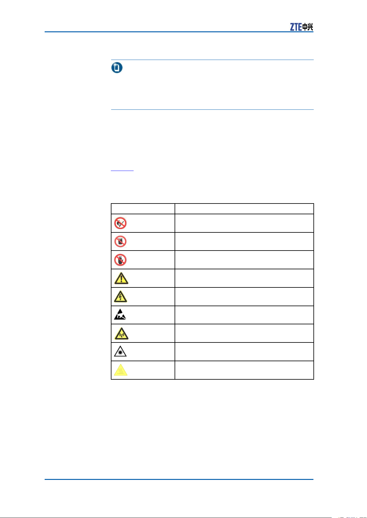
SafetySymbols
a b l e 1 listssafetysymbols.Theyaretoprompttheuserofthe
T
safetyprecautionstobeobservedduringZXSDRBS8800C200
operationandmaintenance.
TABLE1SAFETYSYMBOLSDESCRIPTION
SafetySymbols
Meaning
Nosmoking:Smokingisforbidden
Noflammables:Noflammablescanbestored.
Notouching:Donottouch.
Universalalertingsymbol:Generalsafety
attentions.
Electricshock:Riskofelectricshock.
Electrostatic:Thedevicemaybesensitiveto
staticelectricity.
Microwave:Bewareofstrongelectromagnetic
field.
Laser:Bewareofstronglaserbeam.
Scald:Bewareofscald.
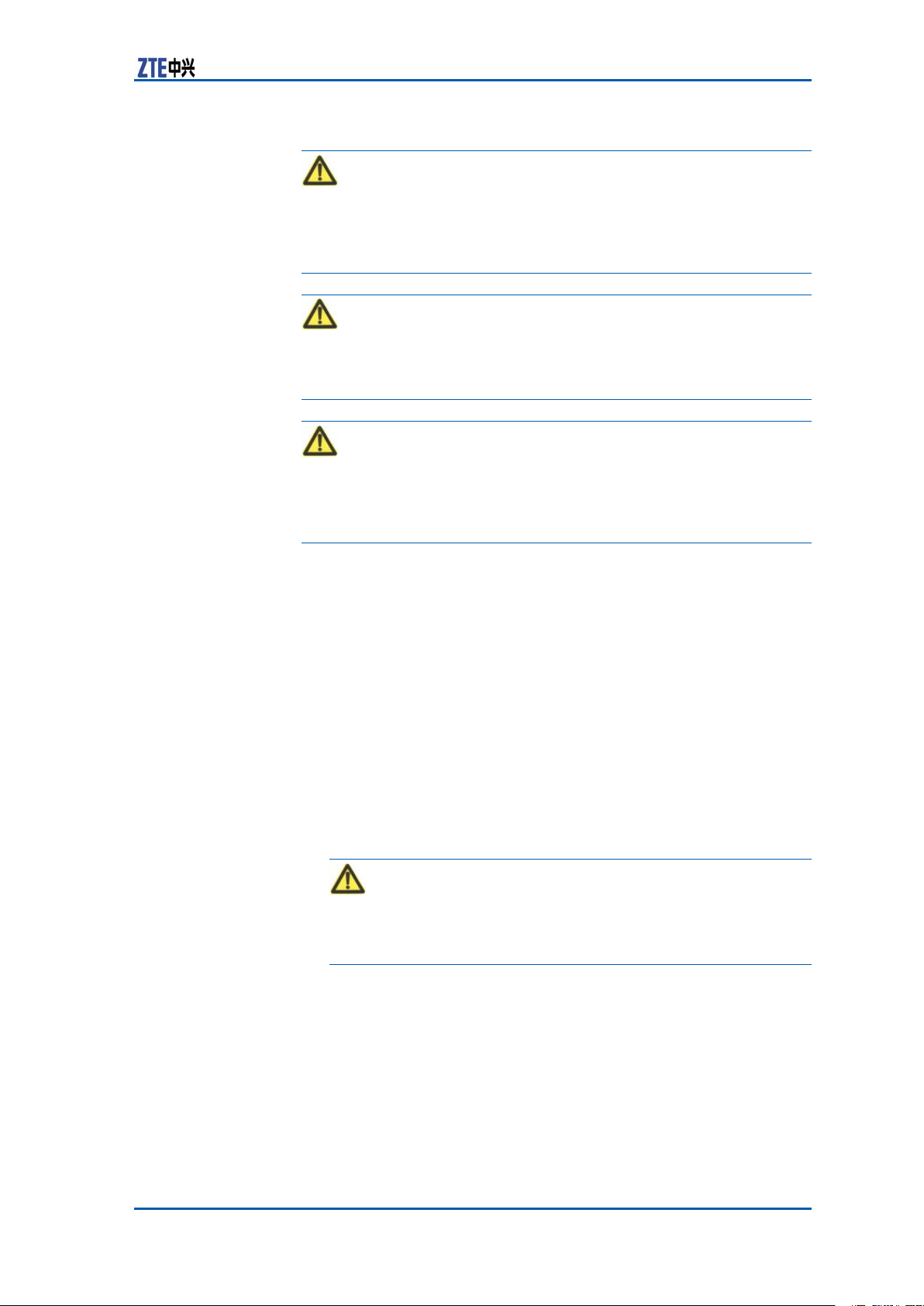
Amongstthesesafetysymbols,theuniversalalarmsymbolsare
classiedintothreelevels:danger ,warning,andcaution.The
formatsandmeaningsofthethreelevelsaredescribedasbelow:
2ConfidentialandProprietaryInformationofZTECORPORATION
Page 11
Chapter1SafetyInstruction
Danger:
Indicatesapotentiallyhazardoussituationwhich,ifnotavoided,
willresultindeathorseriousinjuryofpeople,orequipmentdamagesandbreakdown.
Warning:
Indicatesapotentiallyhazardoussituationwhich,ifnotavoided,
couldresultindeathorseriousinjury.
Caution:
Indicatesapotentiallyhazardoussituationwhich,ifnotavoided,
couldresultinseriousinjuries,equipmentdamagesorinterruption
ofpartservices.
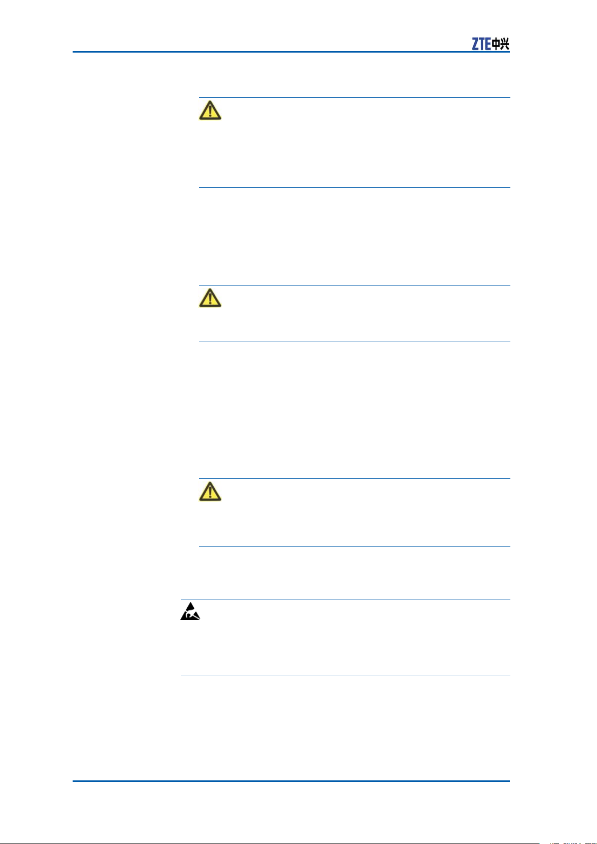
ElectricalSafety
SafetyInstructions
Thissectiondescribesthesafetyinstructionsrelatedtoelectrical
safety,antistatic,heavyobjectsandmodules.
Instructions
Thefollowingaretheelectricalsafetyinstructionsabouttools,high
voltage,powercables,holesandlightning:
�Tools
Usespecialtoolsratherthancommontoolsforhigh-voltage
andACoperations.
�HighVoltage
Danger:
Highvoltageishazardous.Directorindirectcontactwithhigh
voltageormainsupplyusingawetobjectcouldresultindeath.
�StrictlyfollowlocalsafetyrulestoinstallACpowerequip-
ments.
�Installationstaffmustbequaliedforperforminghigh-volt-
ageandACoperations.
�Donotwearanywatch,handchain,bracelet,ringorany
otherconductiveobjectduringsuchoperations.
�Preventmoisturefromaccumulatingontheequipmentdur-
ingoperationsinadampenvironment.
�PowerCable
ConfidentialandProprietaryInformationofZTECORPORATION3
Page 12
ZXSDRBS8800C200InstallationManual
Warning:
Neverinstalloruninstallpowercableswhiletheyarelive.Otherwise,thepowercable,whencontactingaconductor ,mayresultinsparksorelectricarccausingareorevendamageto
eyes.
�Makesuretoshutoffpowersupplybeforeinstallingordis-
connectingapowercable.
�Beforeconnectingthepowercable,makesurethatthecon-
nectingcableanditslabelisappropriatefortheactualinstallationrequirements.
�DrillingHoles
Warning:
Itisnotallowedtodrillcabinetholeswithoutpermission.
AntistaticSafety
�Unqualieddrillingcoulddamagewiringandcablesinside
thecabinet.Additionally ,metalpiecesinsidethecabinet
createdbythedrillingcouldresultinashortcircuit.Use
insulationprotectionglovesandrstmovecablesinsidea
cabinetawaywhendrillingisnecessaryonacabinet.
�Protecteyesduringdrillingasdustoryingdebrismay
damageeyes.
�Cleananydebrisintimeafterdrilling.
�Lightning
Danger:
Donotperformhigh-voltage,AC,irontowerormastoperations
inathunderstorm.
Thunderstormswouldgiverisetoastrongelectromagnetic
eldintheatmosphere.Therefore,theequipmentmustbe
groundedandprotectedintimeagainstlightningstrikes.
Instructions
Electrostatic:
Staticelectricityproducedbyhumanbodycandamagestatic-sensitivecomponentsoncircuitboard,suchaslarge-scaleintegrated
circuits.
�Frictioncausedbyhumanbodyactivitiesistherootcauseof
electrostaticchargeaccumulation.Staticvoltagecarriedbya
humanbodyinadryenvironmentcanbeupto30kV ,and
canremaininthereforalongtime.Anoperatorwithstatic
electricitymaydischargeelectricitythroughacomponentwhen
he/shetouchestheconductorandcausingdamage.
4ConfidentialandProprietaryInformationofZTECORPORATION
Page 13

HoistingHeavy
Chapter1SafetyInstruction
�Wearanantistaticwriststrap(theotherendofwriststrapmust
bewellgrounded)beforetouchingtheequipmentorholding
aplug-inboard,circuitboard,IntegratedCircuit(IC)chipor
otherdevices,topreventhumanstaticelectricityfromdamagingsensitivecomponents.
�Aresistorover1MΩshouldbeconnectedinseriesonthecable
betweentheantistaticwriststrapandthegroundingpoint,to
protecttheoperatoragainstaccidentalelectricshock.Resistanceover1MΩislowenoughtodischargestaticvoltage.
�Theantistaticwriststrapusedmustbesubjecttoregular
check.Donotreplacethecableofanantistaticwriststrap
withanyothercable.
�Donotcontactstatic-sensitivemoduleswithanyobjectthat
easilygeneratesstaticelectricity .Forexample,frictionofpackagebag,transferboxandtransferbeltmadefrominsulation
plasticmaycausestaticelectricityoncomponents.Discharge
ofstaticelectricitymaydamagecomponentswhentheycontactahumanbodyortheground.
�Modulesshouldonlycontactmaterialssuchasantistaticbag.
Keepmodulesinantistaticbagsduringstorageandtransportation.
�Dischargestaticelectricityofthetestdevicebeforeuse,that
is,groundthetestdevicerst.
�DonotplacethemodulenearastrongDCmagneticeld,such
asthecathode-raytubeofamonitor .Keepthemoduleatleast
10cmaway.
Objects
Warning:
Whenhoistingheavyobjects,ensurethatnobodyisstandingor
walkingunderthehoistedobject.
�Ensurethehoistercanmeethoistingrequirementswhendis-
assemblingheavyequipment,ormovingandreplacingequipment.
�Theinstallationpersonnelmustbedulytrainedandqualied
forhoistingoperations.
�Hoistingtoolsmustbeinspectedandcompletebeforeservice.
�Makesurethathoistingtoolsarexedrmlyonasufciently
securedobjectorwallbeforethehoistingoperation.
�Givebrieforalinstructionsduringhoistingoperationstopre-
ventanymishap.
Unplugging/Plug-
gingaModule
�Neverplugamodulewithexcessiveforce,toensurethatthe
pinsonthebackplanedonotgetdeformed.
�Plugthemodulerightintotheslotandmakesuremodulecir-
cuitfacesdonotcontacteachotherlestanyshortcircuitmay
occur .
�Keephandsoffthemodulecircuit,components,connectors
andcabletroughwhenholdingamodule.
ConfidentialandProprietaryInformationofZTECORPORATION5
Page 14

ZXSDRBS8800C200InstallationManual
OtherSafety
Instructions
Note:
Donotperformmaintenanceordebuggingindependently,unless
aqualiedpersonispresent.
�Replacinganypartsormakinganychangestotheequipment
mightresultinanunexpecteddanger .Therefore,besurenot
toreplaceanypartsorperformanychangestotheequipment
unlessauthorizedotherwise.
�DuetothatRRUisinhightemperatureduringrunning,theRRU
shouldbeinstalledinsomeregionsoutofoperators’reachor
strictlyrestricted.
�DuetothatRRUisinhightemperatureduringrunning,theRRU
shouldbeinstalledinsomeregionsoutofoperators’reachor
strictlyrestricted.
�ContactZTEofceifyouhaveanyquestion,toensureyour
safety.
6ConfidentialandProprietaryInformationofZTECORPORATION
Page 15
C h a p t e r 2
InstallationOverview
TableofContents:
Appearance.......................................................................7
EngineeringIndices............................................................7
InstallationFlow.................................................................8
InstallationPrecautions.......................................................9
Appearance
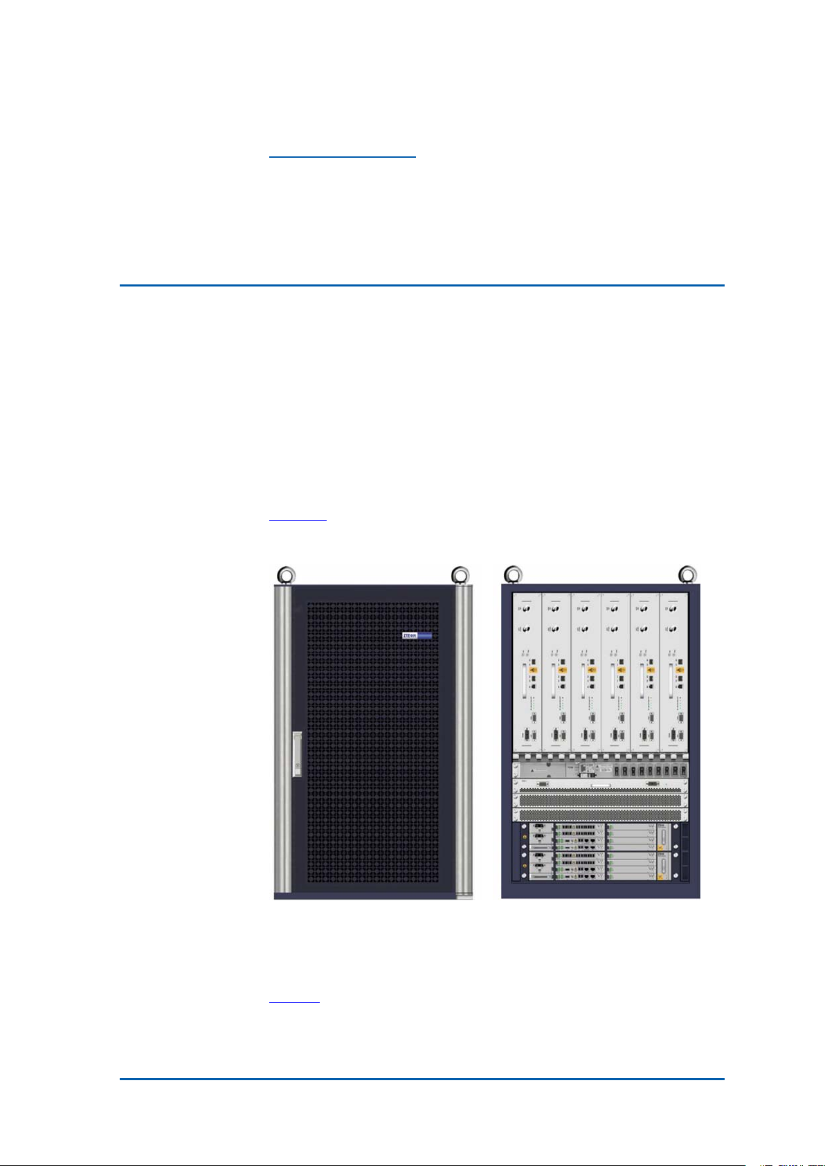
i g u r e 1 showstheappearanceofZXSDRBS8800C100.
F
FIGURE1ZXSDRBS8800C200APPEARANCE
EngineeringIndices
a b l e 2 liststheengineeringindicesofZXSDRBS8800C200.
T
ConfidentialandProprietaryInformationofZTECORPORATION7
Page 16

ZXSDRBS8800C200InstallationManual
TABLE2ZXSDRBS8800C200ENGINEERINGINDICES
Item
Dimension
Weight<200kg
PowerSupply
WorkingTemperat
ure
OverallPower
Consumption
WorkingHumidity
Grounding
Index
950mm×600mm×450mm(height×width
×depth)
-48VDC:-40V~-57V
-40℃to55℃(-40℉to131℉)
<3000W(fullconfiguration)
5%RH~95%RH
<5Ω
InstallationFlow
TheZXSDRBS8800C200installationowislistedinF
i g u r e 2 .
8ConfidentialandProprietaryInformationofZTECORPORATION
Page 17
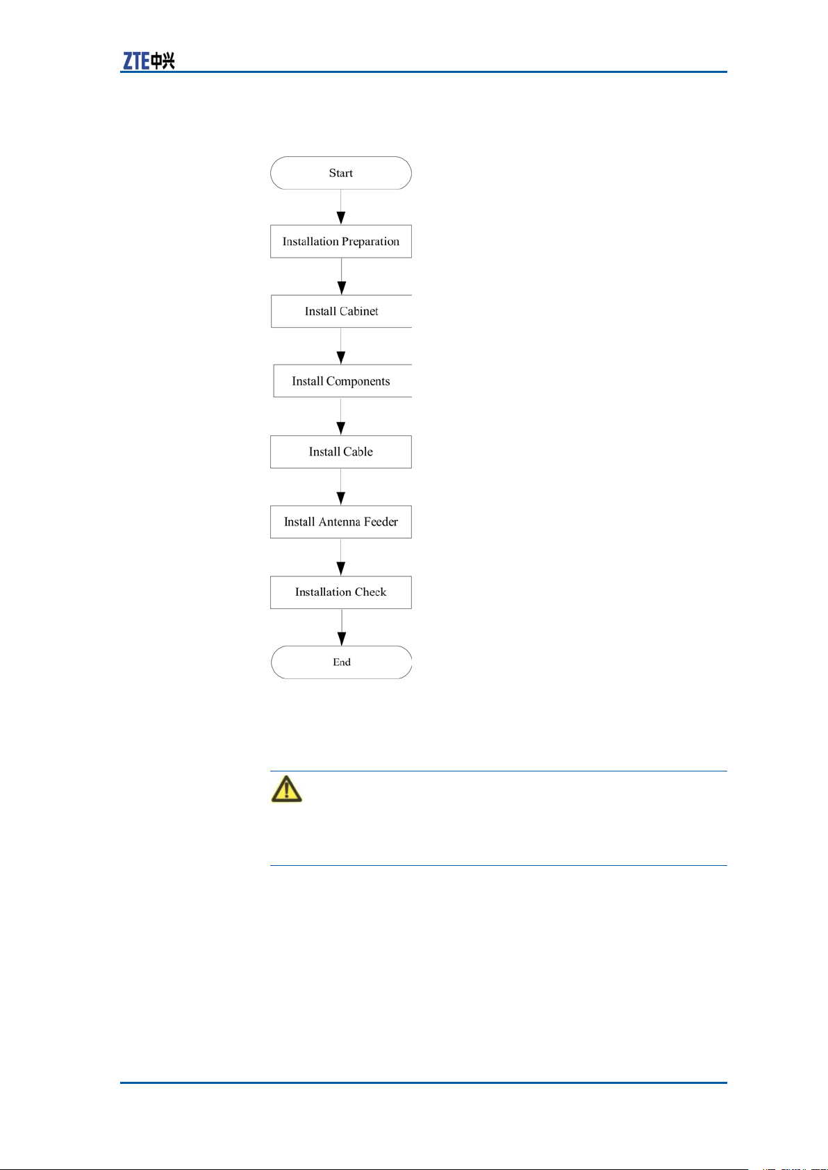
FIGURE2INSTALLATIONFLOW
Chapter2InstallationOverview
InstallationPrecautions
Warning:
Nonprofessionalpersonnelprohibitsinstallinganddebuggingdevicesalone,exceptwithguideofprofessionalpersonnel.
�Readthismanualaswellascorrespondingmanualscarefully
beforeinstallationandperforminstallationaccordingtotheinstallationowandspecicationsinthismanual.
�ZXSDRBS8800C200hardwareinstallationpersonnelmust
participateinsometrainingrelatedtocommunicationequipmentinstallationandownskilledinstallationtechnique.
�Duringinstallation,ensurepersonalsafetyandavoidaccidents
suchaselectricshockorbruise.
ConfidentialandProprietaryInformationofZTECORPORATION9
Page 18

ZXSDRBS8800C200InstallationManual
�Duringinstallationintheequipmentroom,installationper-
sonnelshouldwearinsulationshoesandtakeoffnecklaces,
braceletsandwatches.
�Duringinsertingandextractingboards,installationpersonnel
shouldwearantistaticwriststrapsandmakesuretheother
endofitgrounding.
�Duringinstallationandmaintenanceofopticalber ,prohibit
directlystaringatasectionofopticalberorasocketofoptical
terminalincasethatlaserbeamsdamageeyes.
�Insertboardsalongslots,avoidcontactbetweenparalleled
boardscausingshortcircuit.Makeproperforceincaseofpins
distorted.
�Takeholdoftheedgeofboardsandnottouchthecircuit,com-
ponentsandwires.
�Replacingcomponentsormodifyingdevicesmaybringextra
risks.Withoutauthorization,prohibitreplacingormodifying
devices.
10ConfidentialandProprietaryInformationofZTECORPORATION
Page 19

C h a p t e r 3
InstallationPreparation
TableofContents:
CabinetInstallationEnvironmentCheck................................11
TechnicalMaterialPreparation.............................................17
PersonnelRequirements.....................................................18
ToolsandInstrumentsPreparation.......................................18
UnpackingAcceptance........................................................20
CabinetInstallation
EnvironmentCheck
EquipmentRoomSpace
Requirements
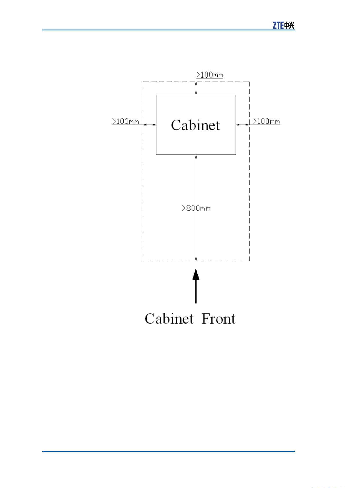
Theminimuminstallationspaceofcabinetisrequiredasshownin
i g u r e 3 .
F
ConfidentialandProprietaryInformationofZTECORPORATION11
Page 20
ZXSDRBS8800C200InstallationManual
FIGURE3INSTALLATIONSPACEREQUIREMENT
Thedetailedrequirementsisasfollows:
�Thisequipmentcanbeinstalledalongsideawallandperform
maintenanceforallboardsundertheconditionthattheback
doorisclosed;keepthecabinetadistanceofmorethan100
mmfromthewall.
�Whenthereareotherequipmentatbothsidesoftheequip-
ment,makeitabuttingagainstotherequipment;whenthere
arewallsatbothsidesoftheequipment,keepadistanceof
morethan100mmfromthebothwalls.
�Keepamorethan800mmspacefromthefaceofequipment.
12ConfidentialandProprietaryInformationofZTECORPORATION
Page 21

EquipmentRoomEnvironment
Requirements
Chapter3InstallationPreparation
RoomLayout
Requirements
EquipmentRoom
Equipment
Building
Thelayoutofequipmentroomincludescabletraylayoutandcabinetlayout.Accordingtotheengineeringdesigndrawing,installationpersonnelshouldmarkandlocatebasedonequipmentroom
spaceandcabinetdimension.
Thedirectionfromfeedertocabinetshouldbeconsideredenough
duringcabinetlayout.Thefeedershouldbeshortaspossibleas
itcan,andthebendingradiusoffeedershouldbenottoosmall.
Iftwocabinetsormorearerequired,themaincabinetshouldbe
putinthemiddleofallcabinets.
Cabinetlayoutadoptingarowormulti-rows(putinthesame
equipmentroomwithBSCorMSC)isdeterminedbythesizeof
equipmentroomandcabinetquantity .
Inordertobeconvenientforoperation,suggestthatcabinetlayout
shouldmeetthefollowingrequirements:
�Thedistancefromcabinettowallshouldbemorethan10cm.
�Arowofcabinetskeeps1mdistanceatleastfromanother
neighboringrowofcabinets.
�Whenmultiplecabinetsareputsidebyside,thesecabinets
shouldkeepinline.
�Thefaceofcabinetkeeps1mdistanceatleastfromanob-
struction.
Theengineeringforequipmentroommustmeetthefollowingrequirements:
�Theleveloordifferencepersquaremeterisnotmorethan2
mm.
�Theoor ,wall,ceiling,reservedinstallationholesandgrooves
ofequipmentroomshouldaccordwiththedesignrequirements.
�Preventwaterontheoutdooroorintotheindooroorwhilein-
stallationholespassesanoutdoorwall.T akemeasuresagainst
dampnessforthegrooves.
�Selectsomematerialwhichisdifculttodeformandcrackfor
hiddenpipes,holesandslotsbetweencoverplates.
�Prepareatemporaryroomtostoreinstallationmaterialsand
devices.
ConfidentialandProprietaryInformationofZTECORPORATION13
Page 22

ZXSDRBS8800C200InstallationManual
Note:
High-voltagepowerwire,strongmagneticled,strongelectrical
sparkaswellasotherfactorsbringingdangerforequipmentroom
mustbeawayfromtheequipmentroom.
Temperatureand
Humidity
NoiseConsideringmaintenancepersonnel’sphysicalandmentalhealth,
FireProtectionThereprotectionconditionsofequipmentroommustmeet:
DustproofThedustproofrequirementsofequipmentroomshouldmeetthe
LightingThelightingconditionsofequipmentroomshouldreachthere-
WaterSupplyand
Draining
Theair-conditiondevicesshouldmeetthefollowingconditions:
�EnvironmentT emperature:-5℃~+45℃(Suggestmaintain-
ingtheenvironmenttemperaturebetween15℃and30℃).
�RelativeHumidity:15%~90%(Suggestmaintainingtherela-
tivehumiditybetween15%and90%).
noiseintheequipmentroomshouldbelowerthan70dB.
�Theindoorwallshouldmaintaindryness,andthewallsurface
andceilingarecoatedwithwhitenoncombustiblelusterless
paintorotherame-retardantmaterials.
�Prohibitstoringammableandexplosivesubstancesandequip
necessaryreprotectiondevices.
following:
�Alldoorsandwindowsshouldbeclosed.
�Ventilationpipelinesintheequipmentroomshouldbecleaned,
andairconditiondevicesshouldbeinstalledwithdustscreens.
�HolesCommunicatingbetweenequipmentroomsandpassage
forcablelayoutshouldbeclosedtodecreasedustowbetween
rooms.
quirementsofequipmentmaintenance.Dailylighting,standby
lightingandemergencylightingsystemsshouldbeprepared.
Pipelinesofwaresupply ,drainingandreprotectionshouldnotbe
equippedinsidetheequipmentroom.
EquipmentRoomPowerSupply
Requirements
Thepowersupplyofequipmentroommustmeetthefollowingrequirements:
�Equipadieselenginetoprovidestandbypower .TheACpower
isresponsibleforpowersupplyalone.Thevoltagerange:380
V±10%;220V±10%.
�ThesupplypowervoltageofDCdistributiondeviceshouldbe
stableandthenominalvalueis-48V(-57V~-40V).
�Thebatterycapacityshouldbeadequate.
14ConfidentialandProprietaryInformationofZTECORPORATION
Page 23

Chapter3InstallationPreparation
�Differentpowersocketsintheequipmentroomshouldhave
obviousmarks.Thepowerelectricityshouldbedistinguished
fromthelightingelectricityobviously .
�Whenthephenomenaofpowerundercurrent,under-voltage
andover-voltageoccur ,thereshouldbesound-and-light
alarms.
�Whileusing220Vor380VACvoltage,paygreatattentionin
caseofelectricshock.
�WhileinstallingDCpower ,makesurepowerpolaritiesconsis-
tent.
ElectricShock:
Whilecheckingpowers,examinethecurrentstatusofallswitches
andwatchoutelectricshock.
LightningandGrounding
Requirements
Thelightningandgroundingintheequipmentroomshouldmeet
thefollowingrequirements:
�Thegroundingresistanceisnotmorethan5Ω.
�Theindoorgroundingsystemconnectsdirectlywithaground-
ingbar .Alldevicegroundingconnectstothisgroundingbar .
Andthenthegroundingbarconnectswiththeprimarygroundingbarofthebuilding.
TransmissionRequirements
TheexternalinterfacesofZXSDRBS8800C200locateontheRSU
modulesandBBUsubsystem,referringtoT
TABLE3ZXSDRBS8800C200EXTERNALINTERFACEINDEXDESCRIPTION
Tran
smis
sion
Categ
ory
E1/T1
M
odule
S
A-d
ata
cable
Inte
rface
Name
B2inter
face
Conn
ector
DB44
Description
ConnectstheZXSDRBS8800
C200withtheBSC;
E1provides75Ωand120Ωload
interfaces;
T1provides100Ωloadinterface.
a b l e 3 .
ConfidentialandProprietaryInformationofZTECORPORATION15
Page 24

ZXSDRBS8800C200InstallationManual
Tran
smis
sion
Categ
ory
Ethe
rnet
cable
RS232/
RS485
monit
oring
cable
Dry
contact
cable
AISG
control
cable
GPS
jumper
M
odule
CC
S
A-d
ata
cable
S
A-d
ata
cable
RSUAISGDB9
CC
Inte
rface
Name
ETH0
ETH1RJ45
B4
B3DB25
ANT
Conn
ector
RJ45
DB9
SMA
Description
ConnectstheZXSDRBS8800
C200withtheBSC.
ConnectstheZXSDRBS8800C200
andPCforLMTmaintenance.
Providesinternalandexternal
environmentmonitoringfor
ZXSDRBS8800C200.
Importdrycontactsignalfrom
externaldevices;
Exportdrycontactsignalfromthis
device.
Controlselectricaladjustment
antenna.
Importsatellitesignalintothe
cabinet.
WiringRequirements
Requirements
Wiring
�Beforelayoutofpowercableandprotectivegroundcable,wrap
cableconnectorswellwithinsulationadhesivetape.
�Thepowercableandprotectivegroundcableshouldbesepa-
ratefromthesignalcable.
�Whenthepowercableandprotectivegroundcableareparallel
withthesignalcable,thedistancefromthesignalcablekeeps
10mmatleastinsidethecabinetand100mmatleastoutside
thecabinet.
�Ifthesignalcableiscrossedwiththepowercable,thecrossed
anglemustbe90°.
�Attheturningofcable,thebendingradiusshouldbemorethan
vetimesofthecablediameter .
�Whenthepowercableconnectstoaconnectingterminalof
distributionpowerboxinsidethecabinet,thewiringshouldbe
straightandtheradianofturningshouldbesmooth.
�Theactualinstallationpositionofcablesshouldbeconsistent
withrequirementsofengineeringsurveyanddataconguration.
�Theroutofcablelayoutshouldbeclearandreasonable,ac-
cordingtotheengineeringdesigndrawing.
�Thelayoutofsignalcableshouldbeorderly ,smoothandnon-
crossed.
�Thelayoutofcablesshouldbeconvenientformaintenanceand
capacityexpansion.
16ConfidentialandProprietaryInformationofZTECORPORATION
Page 25

Chapter3InstallationPreparation
�。Beforefeederlayout,learnofthewiringrouteanddrawa
practicalwiringrouteonthepaperincasefeedercrossed
�Theminimumbendingradiumoffeederisnotlessthan20
timesofthefeederradium.
�Therequirementsoffeederbendingradiumareasshownin
T
a b l e 4 .
TABLE4BENDINGRADIUMREQUIREMENTS
Bending
Super–soft
1/2"Feeder
1/2"Feeder
7/8"Feeder
5/4"Feeder
Requirements
Binding
�Thebindingtapeisboundneatlyandproperly,andthespaces
betweenwirefastenersanddirectionsoffastenerskeepconsistent.
�Cutredundantbindingtapeandmakeitatandtidy.
�Thepowercableandprotectivegroundcableareboundsepa-
ratelyfromthesignalcable.
�Thecablesinsidethecabinetisboundontoawirebushing.
�Whilelayingoutcablesalongthecabletray ,thecableshould
beboundtogetherclose.
�Remainproperlengthincableforinsertingandextractingcon-
nectors.
TheMinimumBendingRadius(recommended) Feeder
BendingforOnce
15cm
50cm125cm
90cm250cm
150cm380cm
ConsecutiveBending
(<=15times)
30cm
TechnicalMaterial
Preparation
Itisnecessarytopreparethefollowingtechnicalmaterialfor
ZXSDRBS8800C200installation:
�ZXSDRBS8800C200CDMAIndoorBasestation-8800Engi-
neeringSurveyReport
�ZXSDRBS8800C200CDMAIndoorBasestation-8800Environ-
mentAcceptanceReport
ZXSDRBS8800C200kitmaterialsinclude:
�ZXSDRBS8800C200CDMAIndoorBasestation-8800T echnical
Manual
�ZXSDRBS8800C200CDMAIndoorBasestation-8800Hard-
wareManual
ConfidentialandProprietaryInformationofZTECORPORATION17
Page 26

ZXSDRBS8800C200InstallationManual
�ZXSDRBS8800C200CDMAIndoorBasestation-8800Installa-
tionManual
�ZXSDRBS8800C200CDMAIndoorBasestation-8800Opera-
tionandMaintenanceManual
�ZXSDRBS8800C200CDMAIndoorBasestation-8800Commis-
sioningandCongurationManual
PersonnelRequirements
InstallationpersonnelshouldparticipateinZTE’strainingandexamination,andhandleknowledgeofinstallationanddebugging.
Afterobtainingjobcerticate,installationpersonnelarequalied
forinstallationanddebugging.
ToolsandInstruments
Preparation
T
a b l e 5 showstoolsandmeterslistrequiredduringinstallation.
TABLE5TOOLANDMETERLIST
Category
Special-purposetools
Concretedrillingtools
Name
Onefeederconnectorknife
Onewirestripper
Onecrimpingpliers
Onemulti-functionalcrimpingpliersEarth
resistancetester
Oneelectricpercussiondrill
Auxiliaryandsamplebits
Onevacuumcleaner
Powersocket(two-phaseandthree-phase
socket,withcurrentcapacitygreaterthan15
A)
18ConfidentialandProprietaryInformationofZTECORPORATION
Page 27

Chapter3InstallationPreparation
Category
General-purposetools
Measurementtools
Protectiontools
Clamptools
Auxiliarytools
Name
Crossscrewdrivers(4”,6”and8”each)
Flatheadscrewdrivers(4,6”and8”each)
Adjustablewrenches(6” ,8” ,10”and12)
Dual-purposespanners(17”and19”each)
Onesetofsocketwrench
5kg(11lb)nailhammer
One300Wiron
One40Wiron
Solderwires
Hotblower
Oilpaintbrush
Pliers
Scissor
Paperknife
One50m(164feet)tapemeasure
One5m(16feet)steeltape
One400mm(16inches)levelbar
Oneanglemeter
Onecompass
Plumb
Antistaticwriststrap
Safetyhelmet
Pairofgloves
Onehacksaw(withseveralsawblades)
Onepairofsharp-nosepliers(8″)
Onepairofdiagonalpliers(8″)
Onepairofslipjointpliers(8″)
Onepairofvices(8″)
Crowbar
Chainwheel
Rope
Ladder
Forklift
ConfidentialandProprietaryInformationofZTECORPORATION19
Page 28

ZXSDRBS8800C200InstallationManual
UnpackingAcceptance
CountingGoods
PrerequisiteThetransportedcargoshouldhavereachedtheinstallationsite.
ContextTherepresentativeofcustomerandtheprojectsupervisormustbe
presentonsiteduringcountingofgoodsreceived.Ifanypartyis
notpresentatthattime,transportermustholdtheresponsibility
foranydifferenceingoods.
Thestepsinvolvedincountinggoodsareasfollows:
Steps1.CheckDeliveryChecklistofZTECorporation.Checktotalnum-
berofgoods,intactnessofpackingboxes,andcheckwhether
arrivalplaceistheactualinstallationplaceagainstpackinglist
numberattachedtopackingboxes.Ifgoodsareintact,start
tounpackandinspectthem.
Note:
Itisrecommendedtounpackthegoodsafterabout30minutes
ofreceivingthecargo,sincethereisapossibilityofmoisture
contentduetotemperaturevariationsifany .
2.Equipmentinspectionlistandunpackingacceptancereportare
presentintherstpackingcarton.Firstly,openrstpacking
cartonandtakeouttheUnpackingAcceptanceReporttocheck
whetherthegoodsreceivedareinaccordancewiththeinspectionlist.
3.Duringthecountingandunpackinginspectionprocess,ifany
materialisfoundshort,orgoodsdamaged,thenll-inUnpack-
ingAcceptanceFeedbackTableandcontactZTEpromptly.
ENDOFSTEPS.
CrateUnpacking
PrerequisitePreparetheappropriatetoolssuchasstraightscrewdriver ,pliers,
andcrowbar .
ContextPerformthefollowingstepstoopenthecrate:
Steps1.Insertastraightscrewdriverintotheslitbetweencrateand
frontcoverboardtomakeitloose;theninsertcrowbartounclenchcoverboard.
2.Pullthecoverboardoutfromthecrate.
3.Removetheotherboardsofthecrate,asshowninF
i g u r e 4 .
20ConfidentialandProprietaryInformationofZTECORPORATION
Page 29
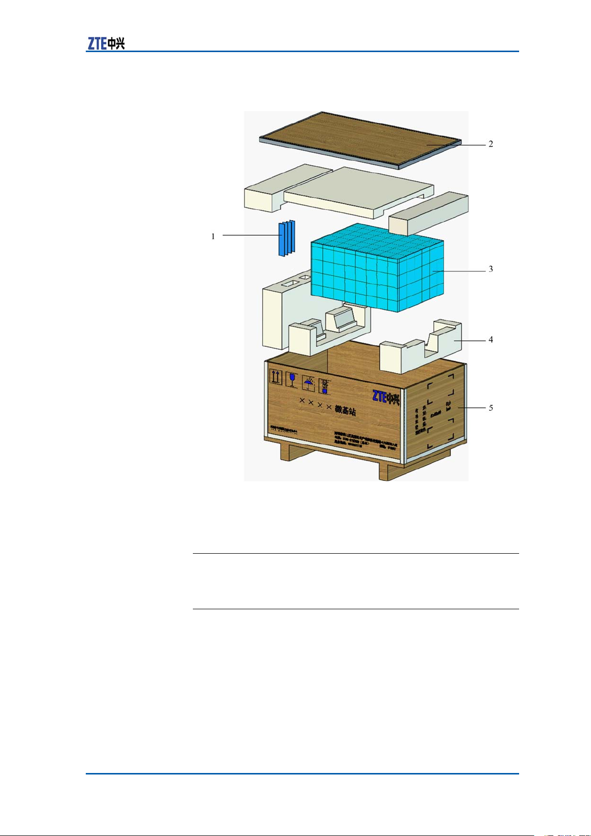
FIGURE4CRATEUNPACKING
Chapter3InstallationPreparation
1.Accessories
2.Coverplate
3.Equipment
4.Foampiece
5.Crate
ENDOFSTEPS.
CartonUnpacking
PrerequisitePreparetheappropriatetoolssuchasstraightscrewdriver ,diago-
nalpliers,andpaperknife.
ContextPerformthefollowingstepstounpackthecarton:
Steps1.Usediagonalplierstocutpackingstraps.
2.Useapaperknifetocutadhesivetapealongtheslitsoncarton
cover ,avoiddamaginggoodsinside.
3.Openthecarton,andremovethefoamboard.
ConfidentialandProprietaryInformationofZTECORPORATION21
Page 30

ZXSDRBS8800C200InstallationManual
4.Checkthegoodswithinthecarton.
Note:
�Avoiddamagingtheantistaticbag(Itcanbeusedinthe
futureforstorageofspareparts)duringunpacking.
�Whiletheequipmentismovedtoahotteranddamper
place,waitfor30minutesbeforeunpackingtheequipment.
Otherwise,moisturemaycondenseonthesurfaceofthe
equipmentandcausedamage.
�Properlydisposeofrecycledesiccants.
ENDOFSTEPS.
AcceptanceandGoodsHandover
ContextPerformthisprocedureforacceptinggoods,andhandingthem
overtooperators.
Steps1.Acceptance
Baseduponthename,categoryandnumbermentionedonthe
shippinglist,carefullycheckthegoodspiecebypiece.Make
surethatgoodsfullthefollowingconditions:
i.Makesurethattherearenobubbly,peeling,nickandlth
markonthesurfaceofthechassis.
ii.Ensurethatoilpaintonthechassissurfaceisintact.
iii.Ensureclampingscrewsaretightandintact.
iv.Allthecomponentsareproperlyinstalledattheirrespective
positions.
v.Laydowntheinspectedgoodsaccordingtocategories.
2.Handover
Aftercompletingtheunpackingprocedure,representativeof
customerandprojectsupervisorshouldapproveandsignUn-
packingforInspectionReport.Eachpartyshouldhaveacopy
ofUnpackingforInspectionReport.Ifthegoodsarestillunderthesupervisionoftheoperatorevenafteracceptance,then
goodswillnotbehandedovertotheoperatoruntilbothparties
signonthereport.
ENDOFSTEPS.
22ConfidentialandProprietaryInformationofZTECORPORATION
Page 31

C h a p t e r 4
InstallingCabinet
TableofContents:
CabinetInstallationFlow....................................................23
InstallingSingle-cabinet.....................................................24
CabinetInstallationFlow
ZXSDRBS8800C200cabinetinstallationowislistedinF
i g u r e 5 .
ConfidentialandProprietaryInformationofZTECORPORATION23
Page 32

ZXSDRBS8800C200InstallationManual
FIGURE5CABINETINSTALLATIONFLOW
InstallingSingle-cabinet
Steps1.Conrmtheinstallationpositionofcabinetbasedontheref-
erencedimensionandcabinetdimensiongivenbytheengineeringdesigndrawing.Measuresomemarkingpointswitha
measuringtapeanddrawtwostraightlinesparalleledwiththe
referencelinewithaninkingpot.Makesuretheholepositions
forcabinetinstallationonthestraightlinesaccordingtothe
designdrawing.Thepositionofsingle-cabinetisasshownin
i g u r e 6 .
F
24ConfidentialandProprietaryInformationofZTECORPORATION
Page 33

FIGURE6SINGLE-CABINETINSTALLATIONPOSITION
Chapter4InstallingCabinet
2.Drillsomeφ12holeswith60mmdepthbasedontheexpansion
boltmarks,asshowninF
FIGURE7HOLING
i g u r e 7 .
Note:
�Whileusingahammerdrilloranelectrichammer ,make
surethedrillbitverticalwiththehorizontalground,clasp
thedrillstockwithhandsandpressitverticallydownwards.
�Whileholing,useacleanertocleandustandmakesure
cleanoutallgarbageafterconstruction.
�Ifthedrillbitisunabletoxduetotoosmoothoor ,in
ordertohelppositioningdrillbit,rstcutaholeonthe
markedpositionswithapunch.
3.Installexpansionnuts.
i.Beforeinstallation,usethecleanertogetridofalldust
insideandoutsideholes.
ConfidentialandProprietaryInformationofZTECORPORATION25
Page 34

ZXSDRBS8800C200InstallationManual
ii.Installfourinsulationsleevesontheinstallationholesto
makesuretheexpansionnutsinsulatedwiththeground,
asshowninF
FIGURE8INSULATIONSLEEVEINSTALLATION
i g u r e 8 .
iii.Inserttheexpansionnutsverticallyintotheinsulation
sleeves,andknockthenutswitharubberhammerto
makethemcompletelyintotheground,asshowninF
9 .
i g u r e
FIGURE9EXPANSIONNUTINSTALLATION
4.Adjustaninsulationsheetandaligntwoholesontheinsulation
sheetwiththoseontheground,asshowninF
FIGURE10INSULATIONSHEETINSTALLATION
i g u r e 1 0 .
26ConfidentialandProprietaryInformationofZTECORPORATION
Page 35

Chapter4InstallingCabinet
5.Aligninstallationholesonthebaseinstallationassemblywith
holesofexpansionnuts.InserttheM10boltthroughabig
washer ,insulationwasher ,installationholeofbaseinstallation
assemblyandinsulationwasherinturn.Screwdownthebolts
andxtheinstallationassemblyonthecementoor ,asshown
i g u r e 1 1 andF i g u r e 1 2 .
inF
FIGURE11BASEINSTALLATIONASSEMBLY(1)
FIGURE12BASEINSTALLATIONASSEMBLY(2)
6.Implementaninsulationtest.
i.Adjustthemultimetertotheresistancegrade.
ii.Forresistancemeasurement,onemeasuringprobeofthe
multimetercontactswiththemetalpartofbaseassembly
andtheotherwiththeexpansionnuts.Ifthecircuitdis-
ConfidentialandProprietaryInformationofZTECORPORATION27
Page 36

ZXSDRBS8800C200InstallationManual
playsanopenstatus,theinsulationtestcompletes.Ifnot,
continuethenext.
iii.Checkwhethertheinsulationsleevesaredamagedorfor-
gottentoinstall.Suchasthissituation,repeattheabove
ow(installthebaseassembly)andperformaninsulation
testagain.
7.Fixthecabinet.
i.Movethecabinettothefrontofbaseassemblyandthe
backofcabinetfacestothebaseassembly .
Note:
Consideringtheweightofcabinet,thetopofcabinetprovidesliftingeyesandsuggestahoistinginstallationmode.
ii.Alignthelocationholesatthebottomofcabinetwiththe
orientationpinboltsonthebaseassembly ,andmovethe
cabinetslowlyandcarefullytomaketwoanglesupports
insertingtheslotsatthebottomofcabinet,asshownin
i g u r e 1 3 .
F
FIGURE13FIXINGCABINET(1)
1.LocationHole
2.OrientationPinBolt
3.AngleSupport
28ConfidentialandProprietaryInformationofZTECORPORATION
Page 37

Chapter4InstallingCabinet
Caution:
Prohibitdrillingholeonthecabinetbyself.Drillinghole
thatdoesnotmeetrequirementswilldamagethecables
andcableconnectioninsidethecabinet.Themetaldust
causedbydrillingwillresultinshortcircuit.
iii.Measurewhetherthecabinetislevelwithalevelbar .Ifnot,
addalevellingsheetunderthecabinettoadjusttolevel.
iv.Openthefrontdoorofcabinetanddisplaytwocircularholes
atthebottom,asshowninF
i g u r e 1 4 .InserttheM10bolt
throughawasher ,insulationwasherandovalhole,and
screwdownthebolt.
FIGURE14FIXINGCABINET(2)
1.CircularHole
Note:
Theinsulationwasherhasbeenrivetedatthebottomof
cabinet.
8.AccordingtoStep6,performasolutiontestformetalcomponentsatthefrontofcabinet.
9.Closethefrontdoorandxthecabinet,asshowninF
ConfidentialandProprietaryInformationofZTECORPORATION29
i g u r e 1 5 .
Page 38

ZXSDRBS8800C200InstallationManual
FIGURE15CABINETINSTALLATIONCOMPLETION
ENDOFSTEPS.
30ConfidentialandProprietaryInformationofZTECORPORATION
Page 39

C h a p t e r 5
InstallingComponents
TableofContents:
ModulePositionSchematicDiagram.....................................31
InstallingRSUModule........................................................33
InstallingBBU...................................................................35
InstallingBBUHorizontalModule.........................................37
InstallingBBUVerticalModule.............................................38
ModulePositionSchematic
Diagram
ZXSDRBS8800
C200Baseband
ThemainmodulesofZXSDRBS8800C200areinstalledintheRF
layerandbasebandlayer .Theinternalstructureisasshownin
ConfidentialandProprietaryInformationofZTECORPORATION31
Page 40

ZXSDRBS8800C200InstallationManual
andRFCabinet
InternalStructure
F
i g u r e 1 6 .
FIGURE16BASEBAND-RFCABINETINTERNALSTRUCTURE
1.RFSubrack
2.CableTray
3.PowerDistributionSubrack
4.FanSubrack
5.Wind-guidePlace
6.BasebandSubrack
RFModuleLayoutTheRFmodulesareconguredintherstsubrack,asshownin
F
i g u r e 1 7 .
32ConfidentialandProprietaryInformationofZTECORPORATION
Page 41

BasebandMoudle
Chapter5InstallingComponents
FIGURE17RFSUBRACKAPPEARANCE
1.RFUnit
SixRSUmulti-carrierRFunitscanbeconguredinSlot1~Slot6.
Layout
ZXSDRBS8800C200basebandsubrackisasshowninF
FIGURE18BASEBANDSUBRACKAPPEARANCE
i g u r e 1 8 .
1.PM
2.FS
3.CC
4.SA
5.CHV
6.FA
7.CHD
InstallingRSUModule
Prerequisite�InstalltheZXSDRBS8800C200cabinetcompletely .
�WearanantistaticwriststraptoavoiddamagingtheRSU.
Steps1.Conrmslotsofmoduletobeinstalled.
2.Holdpartofametalpanelwiththerighthandandsupportthe
lowerpartofRSUwiththelefthand.Inthisway,keepthe
metalpanelerect.
3.Pushthemodulegentlyintoaslotalongaguideway,keepit
erectandlocateupperandlowerendsintotheslots.
4.Holdthemoduleatmiddleandpushitslowlyonce2/3rdof
boardisinserted.Whenthemoduletouchestoabackplane
socket,pushitlittleforciblyandmakeitintothesocketof
backplane.
ConfidentialandProprietaryInformationofZTECORPORATION33
Page 42

ZXSDRBS8800C200InstallationManual
5.ScrewdownsixM5X20panheadassemblyscrewsontheRF
module.
ThepositionsofsixscrewsareasshowninF
FIGURE19SCREWPOSITIONSONRFMODULE
i g u r e 1 9 .
1.M5X20panheadassembly
screw
6.ScrewdownallscrewsasshowninF
RSUgroundingsheet.
i g u r e 2 0 andconnectthe
34ConfidentialandProprietaryInformationofZTECORPORATION
Page 43

FIGURE20SCREWPOSITION
Chapter5InstallingComponents
1.M5*10panheadscrewwith
crossrecessed
ENDOFSTEPS.
InstallingBBU
Prerequisite�InstalltheZXSDRBS8800C200cabinet.
�WearanantistaticwriststraptoavoiddamagingtheBBU.
Steps1.InsertthemoduleintotheZXSDRBS8800C200cabinetalong
theguidewayandxitwithfourM5×16combinedscrews(two
respectivelyatleftandright),asshowninF
i g u r e 2 1 .
ConfidentialandProprietaryInformationofZTECORPORATION35
Page 44

ZXSDRBS8800C200InstallationManual
FIGURE21BBUINSTALLATION
1.M5×16screw
2.ConnectthegroundinglugofBBUtothecabinetwithaM6×16
screw.ThepositionofM6×16screwisasshowninF
FIGURE22M6×16SCREWPOSITION
i g u r e 2 2 .
1.Groundinglug
2.M6×16screw
36ConfidentialandProprietaryInformationofZTECORPORATION
Page 45

Chapter5InstallingComponents
ENDOFSTEPS.
InstallingBBUHorizontal
Module
PrerequisiteBeforeinstallation,makesurewearinganantistaticwriststrapto
avoiddamagingthePCBboard.
ContextThehorizontalmodulesofZXSDRBS8800C200includeasfollows:
�Controlandclockmodule(CC)
�Channelmodule(CH)
�Fabricswitchmodule(FS)
�Sitealarmmodule(SA)
�Powermodule(PM)
Steps1.InsertthemodulesintotheZXSDRBS8800C200subrackalong
theleftandrightguideways,asshowninF
i g u r e 2 3 .
FIGURE23HORIZONTALMODULEINSTALLATION
1.HorizontalInsertionandExtractionHandle
ConfidentialandProprietaryInformationofZTECORPORATION37
Page 46

ZXSDRBS8800C200InstallationManual
2.Holdhandlesatbothsidesofsubracktopushintothemodule
andmakesurethehandlelockedwiththeZXSDRBS8800C200
subrack.
ENDOFSTEPS.
InstallingBBUVertical
Module
PrerequisiteMakesurewearinganantistaticwristwrapincaseofdamaging
thePCBboard.
ContextTheZXSDRBS8800C200verticalmodulesincludethefanarray
(FA)anddustproofassembly.
Steps1.FastentheFAmodulewiththefourself-clinchingboltslocating
atthebottomplateofthefansubrackwithM3×8combination
screws.
2.InsertthedustproofassemblyalongtherightguidewayofFA
subrackandmakesurethatthespringplateontheFAsubrack
isfastenedwiththedustproofassembly ,asshowninF
2 4 .
i g u r e
FIGURE24DUSTPROOFASSEMBLYINSTALLATION
38ConfidentialandProprietaryInformationofZTECORPORATION
Page 47

Chapter5InstallingComponents
3.PushtheequippedFAsubrackanddustproofassemblyintothe
ZXSDRBS8800C200untilhearinglockingsound,asshownin
i g u r e 2 5 .
F
FIGURE25VERTICALMODULEINSTALLATION
ENDOFSTEPS.
ConfidentialandProprietaryInformationofZTECORPORATION39
Page 48

ZXSDRBS8800C200InstallationManual
Thispageisintentionallyblank.
40ConfidentialandProprietaryInformationofZTECORPORATION
Page 49

C h a p t e r 6
InstallingCable
TableofContents:
On-siteCableInstallationList..............................................41
CableInstallationFlow.......................................................42
InstallingDCPowerCable...................................................43
InstallingGroundingCable..................................................46
InstallingDataCable..........................................................47
Installing75ΩE1Cable......................................................49
Installing120ΩE1Cable....................................................51
Installing100ΩT1Cable....................................................52
InstallingAbisInterfaceEthernetCable................................53
InstallingDryContactInput/outputCable.............................55
InstallingRS232/RS485MonitoringCable.............................58
InstallingFiberbetweenBBUandRSU..................................59
InstallingAISGControlCable..............................................59
InstallingGPSJumper........................................................61
InstallingRFJumper..........................................................63
On-siteCableInstallation
List
Internalcablesinstalledonsitearelistedasfollows:
�Internalopticalber
�Receivingdiversitycable
�CascadingEthernetcable
�SApanelcable
Externalcablesinstalledonsitearelistedasfollows:
�Externalpowercable
�Protectivegroundcable
�E1/T1externalcable
�Abis/Iubinterfaceopticalber
�Abis/IubinterfaceEthernetcable
�Drycontactcable
�RS232/RS485cable
�Antennafeederandjumper
ConfidentialandProprietaryInformationofZTECORPORATION41
Page 50

ZXSDRBS8800C200InstallationManual
�GPSjumper
CableInstallationFlow
ThecableinstallationowislistedinF
FIGURE26CABLEINSTALLATIONFLOW
i g u r e 2 6 .
42ConfidentialandProprietaryInformationofZTECORPORATION
Page 51

Chapter6InstallingCable
Note:
�Thetrunkshouldbeselectedaccordingtotheon-sitesituation.
�Generally,theGPSjumperisinstalledbeforedelivery.
InstallingDCPowerCable
Prerequisite1.Layouttherouteandlengthofcablesalongacabletraybe-
tweenthepowercabinetandtheZXSDRBS8800C200.The
powercableandtheprotectivegroundcableshouldbeseparatelyarrangedandbandedfromothercables.Thebanding
distancepersegmentis200mm.The0.2m~0.5lengthat
bothendsisreserved.
Note:
Thepowercableandtheprotectivegroundcableshouldbe
intactandavoidjointsappearinginthemiddleofcables.
2.Makesurethepowersupplyoutputcutoff.
Danger:
Makesurecheckingthestatusofcircuitbreakerinsidethe
powercabinet.Prohibitinstallingpowercablesinalivestatus.
ContextTherearetwoDCpowercables,madeupofstrandsofame-
retardantwire.ThecrosssectionalareaofDCpowercableis16
2
mm
.Oneisa-48Vbluepowerinputcableandtheotherisa
blackgroundcable.
TheappearanceofDCpowercableisasshowninF
FIGURE27DCPOWERCABLEAPPEARANCE
i g u r e 2 7 .
Steps1.Makeblueandblackcableswith16mm
andconnecttheironeendstothepowercabinet.Theother
endsofblueandblackcablesarereservedforstandby.
ConfidentialandProprietaryInformationofZTECORPORATION43
2
crosssectionalarea
Page 52

ZXSDRBS8800C200InstallationManual
2.Leadthe-48VDC(blue)and-48VRTN(black)cablesthrough
thecableinletontheequipmenttop,asshowninF
FIGURE28DCPOWERCABLEINLET
i g u r e 2 8 .
3.Layoutthepowercabletothepowerdistributionsubrackalong
theverticalcabletrayontheleftsideofcabinet.
4.Screwoffthescrewsontheprotectivecoverattheleftsideof
powerdistributionsubrackwithascrewdriver ,andtakeoffthe
protectivecover .
5.Installrespectivelythe–48VDC(blue)and–48VRTN(black)
cablestotheconnectionterminalsofthepowerdistribution
subrack,theconnectionrelationshipasshowninF
i g u r e 2 9 .
44ConfidentialandProprietaryInformationofZTECORPORATION
Page 53

Chapter6InstallingCable
FIGURE29POWERDISTRIBUTIONSUBRACKCONNECTION
1.—48VRTN2.—48VDC
Caution:
RefertoF
i g u r e 2 9 toconnectthepositiveandnegativeelec-
trodesofpowercableandmakesurenotconnectioninreverse.
6.Rextheprotectivecovertothepowerdistributionsubrack.
ENDOFSTEPS.
ResultTheinstallationofpowercableiscompleted,asshowninF i g u r e
3 0 .
ConfidentialandProprietaryInformationofZTECORPORATION45
Page 54

ZXSDRBS8800C200InstallationManual
FIGURE30POWERCABLEINSTALLATIONCOMPLETION
InstallingGroundingCable
Steps1.Basedonthedistancefromthecabinettotheprotective
ground,cutaproperlengthofprotectivegroundcable.
46ConfidentialandProprietaryInformationofZTECORPORATION
Page 55

Chapter6InstallingCable
Note:
Makesuresomecablesleftwhilecutting.
2.InstalltheprotectivegroundcabletothePEbindingposton
theequipmenttop,asshowninF
FIGURE31GROUNDCABLEINSTALLATION
i g u r e 3 1 .
ENDOFSTEPS.
InstallingDataCable
PrerequisiteInstalltheBBUandtheFSboardcompletely.
ContextDuetoahigh—integrationdesignfortheBBU,interfacesonthe
panelarelimited.Adoptadatacablefortransfer ,foritisconvenientforaccessoftheinternal/externalenvironmentmonitoring,
drycontactmonitoringandE1/T1(Abisinterface).Thereisone
interfacetoconnecttheSAmoduleatEndAofdatacable.There
aremultipletri-interfaceatEndB,connectingtheinternal/externalenvironmentmonitoring,drycontactmonitoringandE1/T1.
TheexplodedviewofdatacableisasshowninF
i g u r e 3 2 .
ConfidentialandProprietaryInformationofZTECORPORATION47
Page 56

ZXSDRBS8800C200InstallationManual
FIGURE32DATACABLEAPPEARANCE
1.Groundterminal
2.E1/T1cable
Steps1.Connectthedatacabletothe“Monitoring/Abis”interfaceofFS
3.RS232/RS485
4.Drycontactinput/output
moduleandscrewdowntwoboltsatthejunction.
2.ConnectEndB1tothegroundterminalofcabinet.
3.ConnectEndB2totheDB44connectorofE1/T1cableand
screwdowntwoboltsatthejunction.
4.ConnectEndB3totheDB9connectorofRS485/RS232environmentmonitoringcableandscrewdowntwoboltsatthe
junction.
5.ConnectEndB4totheDB25connectoroftheexternaldrycontactcableandscrewdowntwoboltsatthejunction.
ENDOFSTEPS.
ResultThedatacableisinstalledcompletely ,asshowninF i g u r e 3 3 .
48ConfidentialandProprietaryInformationofZTECORPORATION
Page 57

FIGURE33DATACABLEINSTALLATIONCOMPLETION
Chapter6InstallingCable
1.Groundterminal
2.E1/T1cable
PostrequisiteContinuetoinstalltheE1/T1,RS232/RS485,drycontactin-
3.RS232/RS485
4.Drycontactinput/output
put/outputcables.
Installing75ΩE1Cable
PrerequisiteInstalltheSAmoduleanditspanelconnectioncable.
ContextAbis-interface75ΩE1cableisthetransmissioncablebetween
ZXSDRBS8800C200andBSC,transmittingtheinterfacemessage
betweenZXSDRBS8800C200andBSC.
Theappearanceof75ΩE1cableisasshowninF
ofthecableisaDB44straightconnector .Therearetwotypesof
cable:inF
i g u r e 3 4 ,theabovecablesupportseightE1cablesand
thefollowingsupportsfourE1cables.
i g u r e 3 4 .Enda
ConfidentialandProprietaryInformationofZTECORPORATION49
Page 58

ZXSDRBS8800C200InstallationManual
Note:
IneightE1cable,1–4E1cablesareafxedwithlabelsandothers
arenot.
FIGURE34ABIS/IUBINTERFACE75ΩE1CABLEAPPEARANCE
Steps1.Leadthe75ΩE1cablethroughacableslotonthetopintothe
cabinet.
2.Layoutthe75ΩE1cablealongtheverticalcabletrayatthe
rightsideofcabinettotheB2connector(E1cableconnector)
ofdatacablebelongingtothebaseband.
RefertoI
n s t a l l i n g D a t a C a b l e fortheinstructionofdatacable.
3.ConnecttheDB44connectorof75ΩE1cabletotheB2interface(E1cableinterface)ofdatacablethroughtheSAmodule.
ENDOFSTEPS.
ResultAfterinstallationcompleted,theappearanceof75ΩE1cableis
asshowninF
i g u r e 3 5 .
50ConfidentialandProprietaryInformationofZTECORPORATION
Page 59

FIGURE3575ΩE1CABLEINSTALLATIONCOMPLETION
Chapter6InstallingCable
Installing120ΩE1Cable
PrerequisiteInstalltheSAmoduleanddatacable.
ConfidentialandProprietaryInformationofZTECORPORATION51
Page 60

ZXSDRBS8800C200InstallationManual
ContextThe120ΩE1cableisthetransmissioncablebetweenZXSDR
Steps1.Leadthe120ΩE1cablethroughaslotonthetopintothe
BS8800C200andBSC,transmittingtheinterfacemessagebetweenZXSDRBS8800C200andBSC.
Theappearanceof120ΩE1cableisasshowninF
AofcableisaDB44straightplug.
FIGURE36120ΩE1CABLEAPPEARANCE
Therearetwotypesof120ΩE1:onesupports8E1cablesand
theothersupports4E1cables.Theappearancesoftwocablesare
similar ,butthenumberofcorewireisdifferent.
cabinet.
2.Layoutthe120ΩE1cablealongtheverticalcabletrayatthe
rightsideofcabinettotheB2connector(E1/T1cableconnector)ofdatacable.
RefertoI
3.ConnecttheDB44connectorof120ΩE1cabletotheB2interface(E1/T1cableinterface)ofdatacablethroughtheSA
panel.
ENDOFSTEPS.
n s t a l l i n g D a t a C a b l e fortheinstructionofdatacable.
i g u r e 3 6 .End
ResultAfterinstallationcompleted,theappearanceof120ΩE1cableis
asshowninF
Installing100ΩT1Cable
PrerequisiteInstalltheSAmoduleanddatacable.
ContextThe100ΩT1cableisthetransmissioncablebetweenZXSDR
BS8800C200andBSC,transmittingtheinterfacemessagebetweenZXSDRBS8800C200andBSC.
Theappearanceof100ΩT1cableisasshowninF
AofcableisaDB44straightplug.
52ConfidentialandProprietaryInformationofZTECORPORATION
i g u r e 3 5 .
i g u r e 3 7 .End
Page 61

Chapter6InstallingCable
FIGURE37100ΩT1CABLEAPPEARANCE
Steps1.Leadthe100ΩT1cablethroughaslotonthetopintothe
cabinet.
2.Layoutthe100ΩT1cablealongtheverticalcabletrayatthe
rightsideofcabinettotheB2connector(E1/T1cableconnector)ofdatacable.
RefertoI
3.ConnecttheDB44connectorof100ΩT1cabletotheB2interface(E1/T1cableinterface)ofdatacablethroughtheSA
module.
ENDOFSTEPS.
n s t a l l i n g D a t a C a b l e fortheinstructionofdatacable.
ResultAfterinstallationcompleted,theappearanceof120ΩE1cableis
asshowninF
i g u r e 3 5 .
InstallingAbisInterface
EthernetCable
Prerequisite�ThetransmissionbetweenBTSandBSCisbasedontheIP
bearernetwork.
�InstalltheCCmodule.
ContextBothendsofEthernetcablearecrimpedwiththeRJ45connector ,
asshowninF
i g u r e 3 8 .
ConfidentialandProprietaryInformationofZTECORPORATION53
Page 62

ZXSDRBS8800C200InstallationManual
Steps1.LeadtheAbisinterfacethroughawireinletattherightsideof
FIGURE38ETHERNETCABLEAPPEARANCE
cabinet.
2.LayouttheAbisinterfaceEthernetcablealongtheverticalcabletrayattherightsideofcabinettoCCmoduleofthebase-
band,asshowninF
i g u r e 3 9 .
54ConfidentialandProprietaryInformationofZTECORPORATION
Page 63

FIGURE39ABISINTERFACEETHERNETCABLELAYOUT
Chapter6InstallingCable
3.ConnecttheRJ45connectorofEthernetcabletotheETH0interfaceontheCCmodule.
ENDOFSTEPS.
InstallingDryContact
Input/outputCable
PrerequisiteInstalltheSAmoduleanddatacable.
ConfidentialandProprietaryInformationofZTECORPORATION55
Page 64

ZXSDRBS8800C200InstallationManual
ContextThedrycontactinput/outputcableisusedtoimport/exportdry
Steps1.Leadthedrycontactcablethroughaslotonthetopintothe
contactsignalsfromexternalequipment.
Theappearanceofdrycontactinput/outputcableisasshownin
F
i g u r e 4 0 .EndAofthecableisaDB25straightplugandEndBis
nakedwire.
FIGURE40DRYCONTACTINPUT/OUTPUTCABLEAPPEARANCE
cabinet.
2.Layoutthedrycontactcablealongtheverticalcabletrayat
therightsideofcabinettoSAmoduleofthebaseband.
3.ConnecttheDB25connectorofdrycontactcabletotheB4
interface(DB25)ofdatacablefromtheSAmodule.
ENDOFSTEPS.
ResultAfterinstallationcompleted,theappearanceofdrycableisas
showninF
i g u r e 4 1 .
56ConfidentialandProprietaryInformationofZTECORPORATION
Page 65

FIGURE41DRYCONTACTINSTALLATIONCOMPLETION
Chapter6InstallingCable
ConfidentialandProprietaryInformationofZTECORPORATION57
Page 66

ZXSDRBS8800C200InstallationManual
Prerequisite�InstalltheSAmodule.
ContextTheRS232/RS485monitoringcableprovidesfunctionsofinter-
InstallingRS232/RS485
MonitoringCable
�ConnecttheSApanelconnectioncable(datacable)totheSA
module.
nalandexternalenvironmentmonitoringfortheZXSDRBS8800
C200.Theenvironmentmonitoringinvolvesthesmogmonitoring,
accesscontrolmonitoring,temperatureandhumiditymonitoring,
andoodingmonitoring.TheappearanceofRS232/RS485monitoringcableisasshowninF
signalsisdescribedinT
FIGURE42RS232/RS485MONITORINGCABLE
i g u r e 4 2 .Thedenitionofcore-cable
a b l e 6 .
TABLE6RS232/RS485MONITORINGCABLEDESCRIPTION
Signal
Definit
ion
EndA
PinNo.
Cable
Color
EndB
Name
GNDD0_RS
1
WhiteWhite&Blue
B1
485
–RX_EM
6
Steps1.ConnectEndA(DB9connector)ofRS232/RS485monitoring
0_RS4
85–RX
+_EM
74
cabletotheB3connector(DB9)ofSApanelconnectioncabledatacable.
2.Fastenjunctionsoftheconnectorswithtapes.
ENDOFSTEPS.
GNDD1_RS
Green
485
–RX_EM
8923
White&
Orange
1_RS4
85–RX
+_EM
0_UA
RT-RX
_EM
Blue
B2
1_UA
RT-TX
_EM
O
range
G
NDD
5
W
hite
GND
DB9
metal
sheath
Shie
lding
Layer
Shie
lding
Layer
58ConfidentialandProprietaryInformationofZTECORPORATION
Page 67

InstallingFiberbetween
BBUandRSU
Prerequisite�Installthecabinetcompletely .
�InstalltheZXSDRBS8800C200andallmodules.
ContextTheappearanceofZXSDRBS8800C200opticalberisasshown
inF
i g u r e 4 3 .
FIGURE43OPTICALFIBERAPPEARANCE
Chapter6InstallingCable
Steps1.Connectoneendofopticalbertotheopticalinterfaceofthe
FSmoduleintheZXSDRBS8800C200.
2.ConnecttheotherendofopticalbertotheTX1/RX1optical
interfaceofRSU.
ENDOFSTEPS.
InstallingAISGControl
Cable
ContextTheAISGcontrolcableisusedforcontroloftheelectric-adjust-
mentantenna.Thecablecanfulllalong-distancecontrolofdip
anglesorphasesofantennatoadjustthecoveragerangeofwirelesssignal.
ThestructureofAISGcontrolcableisasshowninF
ConfidentialandProprietaryInformationofZTECORPORATION59
i g u r e 4 4 .
Page 68

ZXSDRBS8800C200InstallationManual
Steps1.ConnectEndAofAISGcontrolcabletothedebugginginter-
ResultTheAISGcontrolcableisinstalledcompletely,asshowninF i g u r e
FIGURE44AISGCONTROLCABLESTRUCTURE
face(AISG)ofZXSDRBS8800C200andfastenscrewsofthe
interface.
2.ConnectEndBofAISGcontrolcabletothecontrolinterfaceof
electric-adjustmentantennaandfastenscrewsoftheinterface.
ENDOFSTEPS.
4 5 .
FIGURE45AISGCONTROLINSTALLATIONCOMPLETION
60ConfidentialandProprietaryInformationofZTECORPORATION
Page 69

InstallingGPSJumper
Prerequisite�Installthecabinetcompletely .
�InstalltheZXSDRBS8800C200andmodules.
�InstalltheGPSarrester .
ContextTheGPSjumperisasectorofcabletoconnecttheGPSinterface
ofCCmodulewiththeGPSarrester ,theappearanceasshownin
F
i g u r e 4 6 .
FIGURE46GPSJUMPERAPPEARANCE
Chapter6InstallingCable
Steps1.ConnectEndAofjumpertothe“REF”antennainterfaceofCC
module.
2.ConnectEndBtotheGPSarrester .
ENDOFSTEPS.
ResultTheGPSjumperisinstalledcompletely ,asshowninF i g u r e 4 7 .
ConfidentialandProprietaryInformationofZTECORPORATION61
Page 70

ZXSDRBS8800C200InstallationManual
FIGURE47GPSJUMPERINSTALLATIONCOMPLETION
62ConfidentialandProprietaryInformationofZTECORPORATION
Page 71

Chapter6InstallingCable
InstallingRFJumper
ContextTheRFjumperisasectionofcabletoconnectthemainfeederwith
theantennafeederinterfaceofZXSDRBS8800C200.Usually,
installtheRFjumperafterthemainfeederinstalledcompletely.
TheRFjumperadoptsanished1/2″typewith5m.
TheinstallationpositionofRFjumperisasshowninF
FIGURE48RFJUMPERINSTALLATIONPOSITION
i g u r e 4 8 .
Steps1.ConnectthemaleDINconnectorofRFjumperwiththefemale
DINconnectorofmainfeeder .
2.ConnectthemaleDINconnectorofRFjumpertotheRFantennainterfaceofRSU.
3.Carryoutwaterproofhandlingforconnectors.
ENDOFSTEPS.
ConfidentialandProprietaryInformationofZTECORPORATION63
Page 72

ZXSDRBS8800C200InstallationManual
Thispageisintentionallyblank.
64ConfidentialandProprietaryInformationofZTECORPORATION
Page 73

C h a p t e r 7
InstallingGPSAntenna
FeederSystem
TableofContents:
GPSAntennaFeederSystemInstallationFlow.......................65
GPSAntennaFeederSystemInstallationPreparation..............66
InstallingGPSAntenna.......................................................66
InstallingGPSFeeder.........................................................73
GPSAntennaFeeder
SystemInstallationFlow
TheinstallationowofGPSantennafeedersystemislistedinF
u r e 4 9 .
FIGURE49GPSANTENNAFEEDERSYSTEMINSTALLATIONFLOW
i g -
ConfidentialandProprietaryInformationofZTECORPORATION65
Page 74

ZXSDRBS8800C200InstallationManual
GPSAntennaFeeder
SystemInstallation
Preparation
TheinstallationpreparationoftheGPSantennafeedersystemis
asfollows:
�PreparetheGPSantenna.
�Assigninstallationpersonnel.
�Preparetechnicaldocuments,toolsandmeasureinstrument.
�MakeconnectorsofGPSfeederandjumper .
InstallingGPSAntenna
GPSAntennaInstallationPosition
GPSAntenna
Installation
Positioning
TheGPSantennainstallationpositionshouldmeetthefollowing
requirements:
�Theinstallationpositionshouldbefarawayfromhighandlarge
buildingsaswellassomebuildingsonthetopofwhichsmall
afliatedconstructionslocate.Theupward—verticallyvisual
angleofantennaismorethan90°.Theinstallationpositionof
antennaisasshowninF i g u r e 5 0 .
FIGURE50GPSANTENNAINSTALLATIONPOSITION
1.Ambientconstructionorother
obstructions
2.GPSantenna
�Theinstallationpositioncannotberadiatedinaneardistance
byafaceofmainlobeofmobilecommunicationantenna.Do
notlocatetheantennaundermicrowavesignalfrommicrowave
antenna,high-voltagecablesandstrongradiationfromaTV
emissiontower .
66ConfidentialandProprietaryInformationofZTECORPORATION
Page 75

Chapter7InstallingGPSAntennaFeederSystem
�Consideringfromlightning,selectthecenterofroofforanin-
stallationposition.Donotinstalltheantennaonthesunkfence
aroundtheroofaswellasatacorneroftheroof,inorderto
preventfromlightning.
�Thereshouldbeotherspecialandsimilarequipmentnearto
theinstallationposition,suchasotheroperation’stower .Make
suretheantennawithinaprotectiveareaofarrester .Ifthereis
noirontowerorarrester ,installaspecialarrestertomeetthe
requirementoflightningdesign.Theleveldistancebetween
arresterandGPSantennashouldkeep2~3mandbe0.5m
higherthanthereceivingconnectorofGPSantennaatleast.
InstallingGPSAntennainVertical
Placement
PrerequisiteFollowingtoolsmustbeready.
�Adjustablespanner
�NormalSpanner
Itisrecommendedtohaveapolewithadiameterbetween30mm
~60mm(48mmisrecommended).Theantennashouldnotbe
installedduringrainandheavywind.
Steps1.OpenthepackageandtakeoutGPSantennaandtheGPSrack.
2.UsetheU-shapeclamptoinstalltheGPSracktothemounting
pole.InsertspringwasherandwasherbetweentheU-shaped
clampandmountingpole.
3.UseM6nuttoxtheU-shapeclampandthepoletogether
rmly.
F
i g u r e 5 1 showsthexingprocess.
ConfidentialandProprietaryInformationofZTECORPORATION67
Page 76

ZXSDRBS8800C200InstallationManual
FIGURE51U-SHAPEDCLAMPINSTALLATION
1.GPSsettledclamp
2.Cablestrip
3.Mountingpole
4.U-shapeclamp
4.FixtheGPSantennatotheGPSsettledclamp.Screwthebolt
(M4x14)tormlyxtheantenna.
ENDOFSTEPS.
ResultF i g u r e 5 2 showstheantennaxedintheverticalposition.
68ConfidentialandProprietaryInformationofZTECORPORATION
Page 77

FIGURE52GPSANTENNAVERTICALINSTALLATION
Chapter7InstallingGPSAntennaFeederSystem
1.GPSsettledclamp
2.Feeder
3.Feederstrip
4.GPSantenna
5.Mountingpole
6.U-shapeclamp
InstallingGPSAntennainHorizontal
Placement
PrerequisiteConrmtheinstallationmodeandinstallationpositionofGPSan-
tenna.
Followingtoolsmustbeready:
�Adjustablespanner
�NormalSpanner
Context�Itisrecommendedtohaveapolewithadiameterbetween30
mm~60mm(48mmisoptimal).
�ThepoleusedtoxGPSantennamustbegroundedwell.
�Theantennacannotbeinstalledduringrainandheavywind.
Steps1.OpenthepackageandtakeoutGPSantennaandtheGPSrack.
2.UsetheU-shapeclamptoinstalltheGPSracktothemounting
pole.
3.TheinstallationsupportofGPSantennaisasshowninF
5 3 .AlignholesontheU-shapeclampwithHole1andHole3,
orHole4andHole6ontheinstallationsupport.Thencover
i g u r e
ConfidentialandProprietaryInformationofZTECORPORATION69
Page 78

ZXSDRBS8800C200InstallationManual
aspringwashandatwasherrespectivelyontheseholesand
fastenthemwithM6screws,asshowninF
FIGURE53GPSANTENNARACKINSTALLATIONSUPPORT
i g u r e 5 4 .
–1~6holeposition
FIGURE54GPSRACKINSTALLATION(HORIZONTALPLACEMENT)
4.FixtheGPSantennatotheGPSsettledclamp.Screwdown
thebolt(M4x14)tormlyxtheantenna.
ENDOFSTEPS.
ResultF i g u r e 5 5 showstheGPSantennaxedhorizontally .
70ConfidentialandProprietaryInformationofZTECORPORATION
Page 79

FIGURE55GPSANTENNAFIXEDHORIZONTALLY
Chapter7InstallingGPSAntennaFeederSystem
1.GPSsettledclamp
2.Feeder
3.Feederstrip
4.GPSantenna
5.Mountingpole
6.U-shapeclamp
InstallingGPSAntennainWall-mount
Mode
PrerequisiteFollowingtoolsmustbeready.
�Adjustablespanner
�NormalSpanner
�Hammer
�ExpansionAnchorBolts(M5x30orM5x40)
ContextForinstallingtheGPSAntennaonthewall,theU-shapeclampis
notnecessary.
Steps1.OpenthepackageandtakeoutGPSantennaandtheGPSrack.
2.UsetheDesigntemplateformarkingholesonthewall.Then
drillholesonthewallaccordingthesizeoftheexpansionanchorboltsthattobeused.
F
i g u r e 5 6 showsthedesigntemplate.
ConfidentialandProprietaryInformationofZTECORPORATION71
Page 80

ZXSDRBS8800C200InstallationManual
FIGURE56DESIGNTEMPLATEFORMARKINGHOLES
3.Inserttheexpansionbolts,andhammerthemtoxproperly.
4.InstallGPSantennaracktothecorrespondingboltposition.
5.Insertaspringwasherandatwasherontoexpansionbolts
andusetheM6nuttoxtherackonthewallrmly.
Note:
Thetorqueusedtoxtheclampis45Nm.
6.FixtheGPSantennatotheGPSsettledclampandscrewthe
M4x14bolttightly.
ENDOFSTEPS.
ResultF i g u r e 5 7 showstheGPSantennaxedonthewall.
72ConfidentialandProprietaryInformationofZTECORPORATION
Page 81

Chapter7InstallingGPSAntennaFeederSystem
FIGURE57GPSANTENNAFIXEDONWALL
InstallingGPSFeeder
GPSFeederSelectionPrinciple
GPSfeederselectioncomplieswiththefollowingprinciples:
�WhenthelengthofGPSfeederislessthan100m,select1/4"
feeder .
�WhenthelengthofGPSfeederismorethan100m,please
contactwithZTElocalofce.
WiringGPSFeeder
PrerequisiteBeforefeederlayout,checklayoutenvironmentsuchastheiron
towerandroof;accordingtotherequirementsofengineeringdesigndrawing,makesuretheplanningandproceduresoflayout.
ContextTakenoticeofthefollowingitemswhileperforminglayoutofthe
GPSfeeder:
�Thefeederpassagefromtheinstallationpositiontotheequip-
mentroomshouldbeunhinderedandaccordswiththewiring
requirements;takesomemeasurementsforrainprotection
andanticorrosion.
�Makeawateravoidancecrookwhilethefeederisimported
fromoutdoorstoindoors;thelowestpointofwateravoidance
crookkeepsaverticaldistanceof200mmatleastfromthe
inletforwaterproof.
�Unusedfeederconnectorsshouldbeprotectedwithsolidma-
terial,suchaspackingbags,fromdamagingthereconnectors
duringcablelayout.
ConfidentialandProprietaryInformationofZTECORPORATION73
Page 82

ZXSDRBS8800C200InstallationManual
Steps1.Attachamarkrespectivelyatthebothendsoffeeder .
�Unfoldthefeederandlayoutit;avoidtwistingaspossibleas
youcan;ifitisnecessaryforbending,makesuretheradiusof
bendingnotlessthantheminimumradiusofbendingpermitted
bycables.
�IftheGPSantennaisinstalledontheroof,xthefeederalong
thewallfootontheroofwithplasticclipswhichsteelnails
areattachedto;keepandistanceof1mbetweenplasticclips;
thedirectionsofplasticclipheadarestaggeredmutuallyand
regularly;twofeedersafterjunctionshouldbeboundtogether
incaseoftwistingmutuallyandbending.
2.Protectthefeederconnectorwithlinen(alsoadoptaantistatic
pagingbagwithprotectivefoam)andfastenthebagwitha
bandingtape.
3.MovetheGPSfeederneartotheGPSantenna.
4.MakeanGPSfeederconnectoratoneendthroughthebiding
tape,connectwiththeGPSantennaandscrewdowntheconnectorclockwise,asshowninF
i g u r e 5 8 .
FIGURE58CONNECTIONBETWEENFEEDERTOGPSANTENNA
1.GPSAntenna
2.Pole
3.HoopIron
4.GPSMountingPanel
5.GPSFeeder
6.FeederBindingT ape
Note:
Whilexingthefeeder ,itisrequiredtoscrewdownthefeeder
clockwise.Soconsideringthesituation,aftercompletingthe
abovestep,layoutthefeeder ,orelseitisinconvenientfor
installation.
5.Accomplishtheperformancemeasureofantennaandfeeder ,
makesurethatthesystemoperationisnormal,andthenmake
74ConfidentialandProprietaryInformationofZTECORPORATION
Page 83

Chapter7InstallingGPSAntennaFeederSystem
awaterproofprotectionatthebackofGPSmountingpanelas
wellasatthejunctionofGPSfeederandGPSantenna.
6.FixtheGPSfeederwiththebindingtapeandcutaredundant
partatlyafterbinding.
ENDOFSTEPS.
InstallingGPS1/4”FeederGrounding
Kit
Prerequisite1.CompletetheinstallationandroutingofGPSfeeder .
2.Prepareinstallationmaterialsandtools.
�Theinstallationmaterialsinclude:
–Groundingkit(tinningcopperbraidattached)
–TwoM6×25hexagonheadscrew(springwasherand
plainwasherattached)
–OneM8×25hexagonheadscrew(springwasherand
plainwasherattached),usedtoconnectthegroundcableandgroundbar .
–Assembled1/4"feedergroundcable
–Apackageoftungoil(10ml).
�Theinstallationtoolsinclude:
–Electricalknife
–M6screwdriver
–M8screwdriver .
ContextOnlyinstalltheGPS1/4"feedergroundingkitbeforethefeeder
comesintotheequipmentroom,anddonotallowtoinstallitat
otheranypositions.
ThestructureofGPS1/4"feedergroundingkitisasshowninF
u r e 5 9 .
i g -
ConfidentialandProprietaryInformationofZTECORPORATION75
Page 84

ZXSDRBS8800C200InstallationManual
FIGURE59GPS1/4"FEEDERGROUNDINGKITSTRUCTURE
1.Groundingkit
2.M6hexagonheadscrew(plain
washerandspringwasherattached)
3.Groundcable
ThestructureofgroundcableisasshowninF
FIGURE601/4"FEEDERGROUNDCABLESTRUCTURE
i g u r e 6 0 .
1.Groundterminal(onthesideof
groundingkit)
2.Φ12heatshrinkablesleeve
76ConfidentialandProprietaryInformationofZTECORPORATION
3.Groundcable
4.Groundterminal(onthesideof
coopergroundbar)
Page 85

Chapter7InstallingGPSAntennaFeederSystem
Steps1.Makesurethegroundingpositionof1/4"GPSfeeder;stripa
sectionofthesheathofGPSfeeder(about25mm)accordingto
thesizeofgroundingkit,andplacethegroundingkitthrough
thestrippedpositionofGPSfeeder .
2.Fastenthegroundterminal(onthesideofgroundingkit,with
twogroundingholes)ontothegroundingkitwithM6hexagon
headscrews,placetheattachedspringwasherandplain
washerbetweenscrewandgroundterminal,andscrewdown
thescrewwithaM6screwdriver .
3.Fastentheothergroundterminal(onthesideofcooperground
bar)ontothecoopergroundbarwiththeM8×25hexagonhead
screw,andplacetheplainwasherandspringwasherbetween
screwandcoppergroundbar .
4.Coveralayeroftungoilontheexposedmetalsurface.
ENDOFSTEPS.
LeadingGPSFeederintoRoom
ContextThisstepisadoptableforanindoorBTS.Whileinstallingthefeeder
foranoutdoorBTS,thestepisnoneed.
Throughafeederhermeticwindow,leadtheGPSfeederintothe
equipmentroom.DetailedstepsrefertoL
R o o m .
e a d i n g M a i n F e e d e r i n t o
ConfidentialandProprietaryInformationofZTECORPORATION77
Page 86

ZXSDRBS8800C200InstallationManual
Thispageisintentionallyblank.
78ConfidentialandProprietaryInformationofZTECORPORATION
Page 87

C h a p t e r 8
InstallingMainAntenna
FeederSystem
TableofContents:
AntennaFeederSystemInstallationPreparation....................79
InstallingIndoorGroundingBar...........................................90
InstallingAntenna.............................................................93
InstallingFeederHermetic-window....................................125
InstallingandGroundingFeederandJumper.......................127
FeederIndoorIngoing......................................................135
PerformingAntennaFeederSystemTest.............................139
PerformingOutdoor-connectorWaterproofProcessing...........140
PerformingFeederHermetic-windowWaterproofProcess-
ing................................................................................142
AntennaFeederSystem
InstallationPreparation
FoundationalFacilityRequirements
IronTowerInordertoinsureequipmentsecurity ,thefollowingmustbeper-
formedduringinstalling:
�Makesuretheheightandstrengthofirontowercomplyingwith
therequirementsofcontract.
�Checkwhetheragroundcopperbararoundtheirontoweris
madeanditsgroundingresistanceaccordswiththerequirements.
�Checkwhethertheplatformofirontowerispreparedaccording
totherequirements.
InstallationPoleNormally,aninstallationpoleismadeofgalvanizedsteeltube.
Theouterdiameterofinstallationpoleis48mm~100mmand
thethicknessoftubeisnotlessthan2mm.Theheightofpole
is3masareference.Duetovariousantennatypes,adjustthe
actualdimensionofpoleaccordingtothespecicationofdifferent
antennas.
Inordertoinsureequipmentsecurity,thefollowingmustbeperformedduringinstalling:
ConfidentialandProprietaryInformationofZTECORPORATION79
Page 88

ZXSDRBS8800C200InstallationManual
CableTrayInordertoinsureequipmentsecurity ,thefollowingmustbeper-
�Forinstallingantennawithapole,thedistancebetweenpoles
shouldaccordwiththerequirementsofengineeringdesign.In
thesamesector ,ahorizontaldiversitydistanceoftwo900MHz
receivingantennasmaintains4m~6m,andthatoftwo1800
MHzreceivingantennasmaintains2m~3m.Ifthereareother
types,complywiththedesigndocument.
�Ontheirontower ,usuallyinstalltheantennapoleontheen-
closureofplatform,morethan1mawayfromthetowerbody .
�Completeantennainstallationandcheckwhetherthepoleis
verticalwiththelevel,anerrornotover1°.
�Installtheantennapoleclosetotheedgeofbuildingtoppos-
sibly.Whileselectingadirectxationmodeonthesideofwall,
makesurethatthewallcansupportadequateintensity.
�Whileadoptingadirectxationmodeonthebuildingtop,make
acementbaseandpreventdrillingonthebuildingtopfrom
causingafaultofwaterproofequipment.
formedduringinstalling:
�Adoptastandardcabletraywith400mmwidthintheequip-
mentroom.Thecabletrayisusuallyinstalledabovethecabinetataverticaldistanceof2600mmfromtheoorofequipmentroom.Afterinstallationcompletion,makesurethatthe
wholecabletrayisunmovable.
�Thelengthsleftofexpansionboltsshouldbeconsistent.After
screwingdownnuts,remainasectionofexpansionboltwith5
mmormorethantwocircles.
�Thepaintcolorsofcabletraykeepconsistent.
�Theindoorcabletrayshouldbegroundedatintervalof5m.
Afterinstallationcompletion,performanelectrictestandmake
suregroundingreliable.
CheckingIncomingMaterial
Steps1.Checkwhetherthepackingoffeederandinstallationacces-
soriesareintact.
2.Checkmaterialappearanceandmakesureitundamaged.
3.Checkwhetherthequantityanddimensionofmaterialsaccord
withtherequirementsofpackinglist.
4.Beforeinstallation,makesureallmaterialsavedaccordingto
therequirements.
ENDOFSTEPS.
80ConfidentialandProprietaryInformationofZTECORPORATION
Page 89

Chapter8InstallingMainAntennaFeederSystem
MakingFeederConnector
ContextMakefeederconnectorsonsite.Suggestthatconnectorsinstalled
atthetowershouldbepreparedandwrappedwithspongebefore
hanginstallation.
Ifafeederconnectorisnotmadecompletely,orisamadeconnectorbutnotconnectedwiththejumper ,performsimpliedwaterproofprocessingforit.Therearetwofeasibleprocessingmethods:
wraptheconnectorwithwaterproofadhesivetape,oraftercoveringaplasticbagwrapitwithwaterproofadhesivetapeagain.
Steps1.Straightenanendofconnector .Thencutandstripoffthe
feedersheathata50mmpositionofftheend,asshownin
F
i g u r e 6 1 .
FIGURE61STRIPOFFSHEATH
2.Putthefeederconnectorintoaslotofcuttingtoolandmake
thisslotclosetothefeedersheathpossibly .Closethecutting
tooslowlyandpressitslightly.Facingthefeederport,rotate
thecuttingtoolclockwiseuntilthefrontbladecutsofftheinner
andouterconductorcompletely.Rotatetwocircleswithslight
pressureagainandmakesurethebackbladeexscindingthe
feedersheath.
3.PutanO-typeringintherstwavetroughofouterconductor ,outsidethefeedersheathandcoveralayeroflubricating
oil.Locatethesidewithscrewthreadoutwards,coverafasteningpiecethroughtheconnectorandpushittotheposition
whereonewavetroughontheouterconductorisuncovered,
asshowninF
FIGURE62O-TYPERINGLOCATION
i g u r e 6 2 .
ConfidentialandProprietaryInformationofZTECORPORATION81
Page 90

ZXSDRBS8800C200InstallationManual
4.Putaspringringintothewavetroughontheouterconductor .
5.Pressafoammaterialinsidetheconnectorfromtheouterconductortotheinnerconductorforcibly.
6.Insertanendofconnectorassemblyintotheinnerconductor
carefullyandinstallit,asshowninF
FIGURE63CONNECTION
i g u r e 6 3 .
7.Movetheconnectorassemblyontothefasteningpieceround
andround.Duringoperation,keeptheconnectorassembly
unmovableandonlyrotatethefasteningpiecewithawrench.
Clearawaycopperscrapsonthefoammaterialwithabrush,
especiallycooperscrapsonthecrosssectionofthefoammaterial,asshowninF
i g u r e 6 4 .
FIGURE64COPPERSCRAPCLEARNESSONTHECROSSSECTION
8.Takeaparttheconnectorandchecktheprolestateofouter
conductor .Theproleofouterconductorshouldbeorderlyand
clean.Whiledisassemblingtheconnector ,rstunscrewthe
connectorassemblyinan1/4circle,thenkeeptheconnector
assemblyunmovableandonlyrotatethefasteningpiecewith
awrench,asshowninF
i g u r e 6 5 .
82ConfidentialandProprietaryInformationofZTECORPORATION
Page 91

Chapter8InstallingMainAntennaFeederSystem
FIGURE65ROTATINGCONNECTORFASTENINGPIECE
9.Rotatethefasteningpieceontotheconnectorassemblyagain,
asshowninF
i g u r e 6 6 .
FIGURE66CONNECTINGASSEMBLY
ENDOFSTEPS.
AssemblingOmnidirectionalAntenna
ContextTheappearanceofomnidirectionalantennaisasshowninF i g u r e
6 7 .
ConfidentialandProprietaryInformationofZTECORPORATION83
Page 92

ZXSDRBS8800C200InstallationManual
FIGURE67OMNIDIRECTIONALANTENNAAPPEARANCE
Steps1.Assembletwoxationclipsofomnidirectionalantennaandfas-
tenjunctionswiththeantenna,asshowninF i g u r e 6 8 .
84ConfidentialandProprietaryInformationofZTECORPORATION
Page 93

Chapter8InstallingMainAntennaFeederSystem
FIGURE68FIXINGOMNIDIRECTIONALANTENNA
1.Omnidirectionalantenna
2.Antennasheath
3.Fixationclip
ConfidentialandProprietaryInformationofZTECORPORATION85
Page 94

ZXSDRBS8800C200InstallationManual
Note:
Therearevariousomnidirectionalantennaswithdifferentinstallationmodes.So,duringthepracticaloperation,perform
installationbasedonaspeciedcondition.
Installaspringwasherandatwasherforantennaxation.
Firstputaatwasherandthenaspringwasher .
2.Connectandscrewdownthejumperconnectorandtheantennaconnector .
3.Performwaterproofprocessingfortheconnectorbetweenantennaandjumper ,referringtoP
W a t e r p r o o f P r o c e s s i n g .
Note:
Iftheabovetwostepsareperformedonthetower ,suggest
wrappingalayerofelectricinsulationadhesivetaperoundthe
connectorrequiredtosealandthenwrappingalayerofsemiconductiveself-adhesivetapeagain.
e r f o r m i n g O u t d o o r - c o n n e c t o r
ENDOFSTEPS.
AssemblingDirectionalAntenna
ContextTheappearanceofdirectionalantennaisasshowninF i g u r e 6 9 .
86ConfidentialandProprietaryInformationofZTECORPORATION
Page 95

FIGURE69DIRECTIONALANTENNAAPPEARANCE
Chapter8InstallingMainAntennaFeederSystem
Therearesomeaccessoriesofdirectionalantenna,asfollows:
�Directional-antennaxationclip,asshowninF
FIGURE70DIRECTIONAL-ANTENNAFIXATIONCLIP
i g u r e 7 0 .
�Depressionangleandelevationangleadjustment,asshownin
i g u r e 7 1 .
F
ConfidentialandProprietaryInformationofZTECORPORATION87
Page 96

ZXSDRBS8800C200InstallationManual
FIGURE71DEPRESSIONANGLEANDELEVATIONANGLEADJUSTMENT
Note:
Thexationclipaswellasdepressionangleandelevationangle
adjustmentmustbebothequippedwithaspringwasherand
atwasher .Firstputaatwasherandthenaspringwasher .
Steps1.Accordingtothemarksatthebackofantenna,makesure
twoxedadjustmentpointsrespectivelyatthetopandbottom
ofantenna(theadjustmentpointatthetopisusedforthe
elevationangleadjustmentandtheadjustmentpointatthe
bottomisusedtoxtheantennaandtherack).
2.Referringtotheaccessoryequipmentdrawingprovidesbysuppliersstrictly ,installallaccessoriestocorrespondingpositions.
3.Connectajumperconnectorwithantennaconnector ,andthen
screwdownthem.
4.Performwaterproofprocessingfortheconnectorbetweenantennaandjumper ,referringtoP
e r f o r m i n g O u t d o o r - c o n n e c t o r
W a t e r p r o o f P r o c e s s i n g .
Connectionbetweendirectionalantennaandjumperaswellas
thejumperconnectorafterprocessingareasshowninF
7 2 .
i g u r e
88ConfidentialandProprietaryInformationofZTECORPORATION
Page 97

Chapter8InstallingMainAntennaFeederSystem
FIGURE72CONNECTIONBETWEENDIRECTIONALANTENNAANDJUMPER
ENDOFSTEPS.
HoistingAntennaandFeeder
ContextWhilehoistingantennaandfeeder ,complywiththefollowing:
�Installationpersonnelonthetowerpullsropeupwardandthe
otherpersonnelunderthetowerdrawstheropetocontrolan
ascendingdirectionofantenna.
�Duringhoisting,makesurenopeoplestandingunderthegoods
hungintheair .Whilewalkingoutoftheplatform,installation
personnelmustwearsafebelts.
�。Somesmallmetalgoodsortools,forexample,antennax-
ationclipsandwrenches,shouldbeputinacanvastoolbag,
sealedandthenhoisted.
�Afterhoistinggoodstotheplatformonthetopoftower ,put
theminasecurepositionandtakesecuritymeasures.
�Theabovemethodisadoptableforhoistingofothergoods.
Steps1.Installaxedpulleyonthetopoftower .
2.Makearopethroughthexedpulleyandtieknotswiththe
ropeatthetwoendsofantenna.
3.Installationpersonnelonthetowerandunderthetowerhoist
theantennatothepositionofxingantennatogether .
HoistingantennaisasshowninF
i g u r e 7 3 .
ConfidentialandProprietaryInformationofZTECORPORATION89
Page 98

ZXSDRBS8800C200InstallationManual
FIGURE73HOISTINGANTENNA
ENDOFSTEPS.
InstallingIndoorGrounding
Bar
PrerequisiteAccordingtotheengineeringdesigndrawing,conrmtheinstalla-
tionlocation.
ContextAnindoorgroundingbarisusedtoconnectaprotectiveground
withaworkground.F
groundingbar .
i g u r e 7 4 showsthestructureofindoor
90ConfidentialandProprietaryInformationofZTECORPORATION
Page 99

Chapter8InstallingMainAntennaFeederSystem
FIGURE74INDOORGROUNDINGBARSTRUCTURE
1.M8bolt
Whileinstallingtheindoorgroundingbar ,accordwiththefollowing
requirements:
�Installtheindoorgroundingbaronthewallwhichisneartoa
cabinetandisthesameheightwithacabletray .
�Theindoorgroundingbarshouldbexedparallellyonthewall.
�Whileinstallingexpansionbolts,useaninsulationwasherand
makesurethegroundingbarinsulatedwiththewall.
StepsFixthegroundingbaronthewallwithexpansionbolts,asshown
inF
i g u r e 7 5 andF i g u r e 7 6 .
ConfidentialandProprietaryInformationofZTECORPORATION91
Page 100

ZXSDRBS8800C200InstallationManual
FIGURE75INDOORGROUNDINGBARINSTALLATION(1)
1.M12bolt
2.Springwasher12
3.Bigatwasher
4.Insulationwashera
5.Insulationwasherb
6.Expansionpipeandexpansionnut
FIGURE76INDOORGROUNDINGBARINSTALLATION(2)
1.M12bolt
2.Springwasher12
3.Bigatwasher
4.Insulationwashera
5.Indoorgroundingbar
6.Insulationwasherb
7.Expansionpipeandexpansionnut
ENDOFSTEPS.
92ConfidentialandProprietaryInformationofZTECORPORATION
 Loading...