


MAINTENANCE MANUAL FOR ROUGH TERRAIN CRANE
Address:Quantang Indust=rial Park, 2nd Yuanda Road, Changsha Economic and Technological Development Zone, Hunan Province, China
Postcode: 410131 Website: www.zoomlion.com

MAINTENANCE
MANUAL
Edition 1
Dec 2013
Dec 2013

(Thank you letter)
Owners, Users and Operators:
Zoomlion Cranes appreciates your selection of the ZOOMLION Rough Terrain Crane for your application.
No one should do the maintenance/service tasks to the crane unless they read and know the data in this manual and the other technical documents supplied with the crane.
The Maintenance and Service Manual provides periodic inspections, maintenance and service procedures that are necessary to make sure the performance, safety and reliability are at the highest level. They can also increase the service life of the crane.
When you follow the instructions in this manual, your crane can operate at MAXIMUM EFFICIENCY.
To look after your rights & interests and safety, you must obey all safety data in the Maintenance and Service Manual. Only approved personnel can disassemble and adjust hydraulic system components during maintenance. When a hydraulic component malfunctions or is damaged, tell the local repair facility.
You do not have to keep the Maintenance & Service Manual in the cab of the crane. The Maintenance & Service Manual must be with the crane if it is sold.
If there is something in the manual that you do not understand, speak with us. We (Zoomlion Cranes) are NOT responsible for damages from an operator or service technician who does not obey the instructions in the Maintenance and Service Manual.
THANK YOU!
Mobile Crane Branch Company of ZOOMLION Heavy Industry Science and Technology Co., Ltd
Copyright
Under the copyright laws, this manual cannot be copied, photocopied, reproduced, translated, or reduced to any electronic medium or machine readable form, in whole or part, without the prior written consent of Zoomlion Heavy Industry Science and Technology Co., Ltd.
Copyright © 20XX, Zoomlion Heavy Industry Science and Technology Co., Ltd.
All rights reserved. Printed in the United States
Edition 2 |
Page i |
Dec/2013 |
|

Edition 2 |
Page ii |
Dec/2013 |
|

Contents
(Thank you letter)......................................................................................................................... |
i |
|
Contents |
.................................................................................................................................... |
iii |
About This Manual...................................................................................................................... |
v |
|
Safety ....................................................................................................................................... |
|
vii |
Introduction............................................................................................................................ |
1 |
|
1.1 ....................................................................................................... |
INTRODUCTION |
1 |
1.2 .................................................................................... |
OPERATOR OBSERVATION |
1 |
1.3 ....................................................................... |
WIRE - ROPE INSPECTION RECORD |
3 |
1.4 .......................................................................................... |
ENGINE MAINTENANCE |
4 |
1.5 ....................................................................... |
ENGINE RADIATOR MAINTENANCE |
7 |
1.6 ............................................................................ |
TRANSMISSION MAINTENANCE |
8 |
1.7 ............................................................................... |
AXLE MAINTENANCE CHECK |
10 |
1.8 ................................................................................ |
TIRE MAINTENANCE CHECK |
11 |
1.9 .......................................................................... |
BRAKE SYSTEM MAINTENANCE |
14 |
1.10 ................................................................................ |
AIR SYSTEM MAINTENANCE |
15 |
1.11 ..................................................................................... |
BATTERY MAINTENANCE |
15 |
1.12FUEL, COOLANT AND TORQUE CONVERTER HYDRAULIC TRANSMISSION
|
OIL .......................................................................................................................... |
16 |
1.13 |
LUBRICATION ........................................................................................................ |
17 |
1.14 |
HYDRAULIC OIL..................................................................................................... |
24 |
1.15 |
GEAR OIL ............................................................................................................... |
28 |
1.16 |
LUBRICATING GREASE......................................................................................... |
30 |
1.17 |
LUBRICATING POINTS .......................................................................................... |
31 |
1.18 |
ADJUST, CLEAN AND REPLACE THE PARTS...................................................... |
33 |
1.19 |
BATTERY MAINTENANCE AND SERVICE ............................................................ |
50 |
1.20 |
BATTERY MAINTENANCE – WINTER ................................................................... |
51 |
1.21 |
OPERATION IN WINTER........................................................................................ |
52 |
1.22 |
OPERATION IN SUMMER...................................................................................... |
53 |
Troubleshooting.......................................................................................................................... |
1 |
|
Edition 2 |
|
Page iii |
Dec/2013 |
|
|

2.1 |
ELECTRICAL SYSTEM ............................................................................................. |
1 |
2.2 |
HYDRAULIC SYSTEM ............................................................................................ |
12 |
2.3 |
EXTEND / RETRACT SYSTEM ............................................................................... |
13 |
2.4 |
DERRICKING MECHANISM ................................................................................... |
14 |
2.5 |
SWING MECHANISM ............................................................................................. |
15 |
2.6 |
HOIST MECHANISM ............................................................................................... |
16 |
2.7 |
OUTRIGGERS ........................................................................................................ |
17 |
2.8 |
TRANSMISSION ..................................................................................................... |
18 |
2.9 |
BRAKE SYSTEM .................................................................................................... |
21 |
2.10 |
STEERING SYSTEM .............................................................................................. |
22 |
2.11 |
FRONT / REAR AXLES ........................................................................................... |
25 |
2.12 |
DRIVE SHAFT ......................................................................................................... |
27 |
2.13 |
TIRES ...................................................................................................................... |
28 |
2.14 |
ENGINE ERROR CODE .......................................................................................... |
30 |
2.15 |
TRANSMISSION ERROR CODE ........................................................................... |
40 |
Inspection |
................................................................................................................................. |
84 |
3.1 ..................................................................................... |
PRE - START INSPECTION |
84 |
3.2 ........................................... |
NEW CRANE SPECIAL BREAK - IN REQUIREMENTS |
88 |
3.3 ............................................................. |
PERIODIC INSPECTIONS AND SERVICE |
88 |
3.4 ......................................................................... |
PERIODIC CRANE INSPECTIONS |
96 |
3.5 .................. |
INSPECTIONS AND MAINTENANCES DURING BREAK - IN PERIOD |
103 |
3.6 ................................................................................... |
FILTER ELEMENTS LISTS |
104 |
3.7 ...................................................................... |
FLUID VOLUME REQUIREMENTS |
106 |
Edition 2 |
Page iv |
Dec/2013 |
|

About This Manual
General
The data (data, specifications, illustrations) in this manual is for cranes in production at the time of this manuals publication. We reserve the right to make changes to this manual at any time, without obligation.
This manual is for maintaining and servicing the RT Crane in the field. Follow the operation and maintenance procedures to make sure that your machine operates at MAXIMUM EFFICIENCY. Use the CRANE PERIODIC INSPECTION CHECKLIST. Keep a maintenance log to monitor all maintenance work on the machine.
An example of a Maintenance Log and Crane Periodic Inspection Checklist is at the end of this section.
Again, we at ZOOMLION appreciate your selection of our crane. User safety is most important. To complete on-site tasks safely, operators and service technicians must be responsible. Obey the instructions that follow:
∙Comply - with Occupational Safety and Health Administration (OSHA), Federal, State and Local Regulations.
∙Read, Understand and Follow - the instructions in this and other manuals and documents that come with the crane.
∙Use Good, Safe Work Practices - in a common sense way.
∙Only have trained operators and service technicians - directed by informed and knowledgeable job-site supervisors.
∙Do not use this crane - before the portable fire extinguisher, installed in the cab, agrees with local fire protection rules.
Edition 2 |
Page v |
Dec /2013 |
|

OSHA prohibits the alteration or modification of this crane without written manufacturer’s approval. Use only the factory approved parts to service or repair the crane.
If you make modifications/additions which affect the safe operation of the equipment to the crane before you use it, the crane owner must make sure that the modifications/additions agree with OSHA 1926:1412.
Speak with us if special data is necessary for the maintenance or operation of your RT Crane. Send your machine model and a serial number to make sure that you receive the correct data.
If there is anything in this manual that is not clear or which you think is necessary, write to the address that follows:
Rough Terrain Crane R & D Institute
Zoomlion Mobile Crane Branch Company
Quantang Industrial Park, 2nd Yuanda Road,
Economic and Technological Development Zone,
Changsha, Hunan Province, China, 410131
You can also speak to us by telephone at 0086-84671997 (international), 0731-84671997 (in China).
Thank You!
Edition 2 |
Page vi |
Dec /2013 |
|

Safety
The safety symbol, used on the Danger, Warning and Caution labels, tells personnel of possible death, injury, or property damage. Obey all safety data that follows this symbol to prevent dangerous conditions.
HAZARD CLASSIFICATION
Hazard classification is a system to show different classes of possible injury levels. A safety symbol and a signal word show how dangerous the level of possible injury can be.
A signal word without a safety symbol refers to property damage, protection devices, or important data. You will find this system used in this manual and on signs on the crane to help find and prevent dangerous situations.
HAZARD INDICATORS
DANGER, WARNING, CAUTION and NOTE labels are on signs and decals and as you read this manual to show important instructions. In this manual, DANGER, WARNING and CAUTION labels are before the paragraph or item to which they apply. NOTEs follow the paragraph or item they apply to. The labels are as follows:
Refers to a dangerous situation which, if you do not prevent, will cause death or injury.
Refers to a possible dangerous situation which, if you do not prevent, could cause death or injury.
Refers to a possible dangerous situation which, if you do not prevent, may cause light or moderate injury.
Refers to a tip or hint in the instructions.
INTENDED USE |
|
Edition 2 |
Page vii |
Dec /2013 |
|
Scope
The owner of this crane must know federal, state and local rules. When your equipment is in operation, the area must be safe for employees and non-employees. Do not cause damage to other equipment or local structures while you operate this crane. Rules change by location and this manual does not give that data.
ZOOMLION makes manuals for different construction and industrial equipment. It is policy to include applicable national consensus, industry standards and safety data with the manuals. Use this data to give applicable training to personnel who are to operate, do the maintenance and supervise the equipment correctly and safely.
We make equipment for heavy-duty labor. Do periodic inspections regularly because the equipment wears during operation. This prevents accidents, decreases downtime and helps equipment work satisfactorily. The goal of these inspections is to find worn, cracked, damaged parts and loose or missing fasteners before they cause a problem.
Correct training and inspection procedures are necessary to prevent injury to persons, property damage and high maintenance costs.
Read and understand the data that comes with this crane. Help is available from the distributors of your ZOOMLION crane and from the ZOOMLION manufacturing facility.
This manual contains the instructions and data on the operation, maintenance, lubrication and adjustments of the Rough Terrain Crane. Do not operate or service the crane before you understand the data in this manual.
Edition 2 |
Page viii |
Dec /2013 |
|
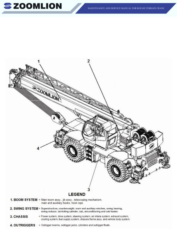
Nomenclature
To help you understand the contents of this manual, refer to the figure below. Each numbered term can represent several components of the same main part.
Edition 2 |
Page ix |
Dec /2013 |
|

CRANE PERIODIC INSPECTION CHECKLIST
This inspection checklist provides supplementary data to facilitate the correct operation and maintenance of the crane.
Component |
Inspected |
Interval |
Function |
Adjusting |
Condition |
Maintenance |
Condition |
|
Component |
Inspected |
Inspection |
Code |
Function |
Adjusting |
Condition |
Maintenance |
Condition |
|
|
|
|
|
|
|
|
|
|
|
|
|
|
|
|
|
|
|
|
|
|
|
|
|
|
|
|
|
|
|
|
|
|
|
|
|
|
|
|
|
|
|
|
|
|
|
|
|
|
|
|
|
|
|
|
|
|
|
|
|
|
|
|
|
|
|
|
|
|
|
|
|
|
|
|
|
|
|
|
|
|
|
|
|
|
|
|
|
|
|
|
|
|
|
|
|
|
|
|
|
|
|
|
|
|
|
|
|
|
|
|
|
|
|
|
|
|
|
|
|
|
|
|
|
|
|
|
|
|
|
|
|
|
|
|
|
|
|
|
|
|
|
|
|
|
|
|
|
|
|
|
|
|
|
|
|
|
|
|
|
|
|
|
|
|
|
|
|
|
|
|
|
|
|
|
|
|
|
|
|
|
|
|
|
|
|
|
|
|
|
|
|
|
|
|
|
|
|
|
|
|
|
|
|
|
|
|
|
|
|
|
|
|
|
|
|
|
|
|
|
|
|
|
|
|
|
|
|
|
|
|
|
|
|
|
|
|
|
|
|
|
|
|
|
|
|
|
|
|
|
|
Edition 2 |
Page x |
Dec /2013 |
|

MAINTENANCE LOG
Item |
|
Adjusting Condition |
|
Date |
|
|
|
|
|
|
|
|
|
|
|
|
|
|
|
|
|
|
|
|
|
|
|
|
|
|
|
|
|
|
|
|
|
|
|
|
|
|
|
|
|
|
|
|
|
|
|
|
|
|
|
|
|
|
|
|
|
|
|
|
|
|
|
|
|
|
|
|
|
|
|
|
|
|
|
Edition 2 |
Page xi |
Dec /2013 |
|

Edition 2 |
Page xii |
Dec /2013 |
|

MAINTENANCE AND SERVICE MANUAL FOR ROUGH TERRAIN CRANE
Chapter 1 Maintenance and Service

Introduction
1.1INTRODUCTION
Aset of preventive maintenance tasks is necessary to extend the serviceable life of the crane. The tasks can help to maximize efficient service and decrease the time the crane is at the repair facility. This section has checks and procedures which you are to do on daily, weekly, monthly and semi-annual intervals. These intervals are specified in conditions of calendar and hours of operation.
The checks for long intervals include all the checks that you do in the shorter intervals. Thus, the weekly check includes all items in the daily check. The monthly check includes the weekly and the daily checks. The semi-annual check includes the quarterly, monthly, weekly and daily checks.
The chart makes it possible for you to record the preventive maintenance tasks that you complete. It also supplies you with a tool to find the problem areas and to examine the value of the maintenance tasks. The items in each check interval on the chart are assembled by their applicable headings and explained in this chapter.
This maintenance schedule is a procedure to make sure that basic preventive maintenance tasks are completed in the usual conditions that you operate. The conditions which increase wear, loads or strain on the crane, usually make it necessary to decrease the interval time. Before you change the maintenance schedule, examine your operation and the maintenance records of the crane. Think about all the factors involved and make a new schedule that is sufficient to align the usual maintenance tasks.
As a part of each preventive maintenance check, refer to the Engine Manufacturer’s Manual for engine maintenance tasks. When you do the servicing of the engine, use the data in the engine manual if this chapter has data that is different.
1.2OPERATOR OBSERVATION
A.Do a visual inspection for:
(1)Unusual conditions
(2)Hydraulic system leaks or damage.
B.Examine the area around the engine for:
(1)Belts (tension and wear)
(2)Coolant level
(3)Engine oil level
(4)Hydraulic transmission oil level
Edition 2 |
Chapter 1 |
Page 1-1 |
Dec /2013 |
Maintenance |
|

(5)Air cleaner vacuum actuated indicator
(6)Air inlet
(7)Silencer and exhaust device.
C.Examine the condition of each battery.
D.Examine the boom for:
(1)Sheave (wear or damage)
(2)The function of the anti-two block system
(3)Wire-rope on the winches (wear and breaks)
(4)Wear of the cylinder pin.
E.Tires, axles and drivelines (wear or damage).
F.Examine the cab for:
(1)Gauge and indicator functions
(2)Function of the switches and joysticks
(3)Clear windows
(4)Safety device in position
(5)Each light operates
(6)Cleanliness: free from dirt, mud and waste material.
Edition 2 |
Chapter 1 |
Page 1-2 |
Dec /2013 |
Maintenance |
|

1.3 WIRE-ROPE INSPECTION RECORD |
|
WIRE-ROPE INSPECTION RECORD |
|
(See pages 1-37 and 1-38) |
|
Place of inspection ________________________ |
Date _______________ |
DESCRIPTION OF CRANE |
|
Make _____________________________Model_________ |
Serial No. ___________ |
Type and Arrangement of Attachments___________________________________________
Date of Last Rope Inspection __________________________________________________
Hours and Time of Service Since Last Inspection ___________________________________
RESULT OF INSPECTION |
|
|
|
Rope Inspected |
Type and Size |
Conditions noted |
Recommendations |
_________________________________________________________________________
_________________________________________________________________________
_________________________________________________________________________
_________________________________________________________________________
_________________________________________________________________________
_________________________________________________________________________
___________________ Inspector:
Edition 2 |
Chapter 1 |
Page 1-3 |
Dec /2013 |
Maintenance |
|
1.4ENGINE MAINTENANCE
For Cummins engine maintenance, refer to the EngineManufacturer’s Manual.
Engine productivity, longevity and low-cost performance depend on a regular program of periodic maintenance. The materials presented here are listed in accordance with the EngineManufacturer’s Manual. Consideration may dictate a revision in scheduling for the periodic checks.
A good periodic preventive maintenance program can increase the productivity, longevity and low-cost performance of the engine. The data, in this section of the manual, is from the data in the EngineManufacturer’s Manual. You can change the interval or schedule of the preventive maintenance program because of the area and the types of operations you do.
A. Daily Inspections:
(1)Fuel Level
(a)You can find the fuel tank on the left side of the crane (Figure 1-1). If you keep the tank full of fuel, in cold weather, you can decrease the quantity of condensation.
Figure 1-1 Fuel Tank Cap
(b)Use a good grade of diesel fuel. The tank capacity is 79 gal. (300 l).
Edition 2 |
Chapter 1 |
Page 1-4 |
Dec /2013 |
Maintenance |
|
(2)Engine Oil Level
(a)You can measure the level of oil in the engine by a dipstick. The dipstick is on the right side of the engine (aft end of the crane). The engine must be OFF and sit for a short time before you can measure the oil level. Wait for 15 minutes, after you stop the engine, to measure the level. Adjust the level of oil to the full mark.
(b)Do not overfill!
Do not operate the crane if the level of engine oil is too low or too high.
(3)Water Separator
(a)The fuel line contains a water separator. It removes the condensation and contamination from the fuel before it goes into the engine. You must examine the water separator before you operate the crane to drain the condensation and contamination.
(b)Do not let the water separator fill more than 1/2 full.
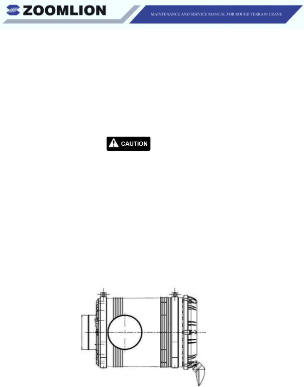
(4)Air Filter
(a)Examine the air filter and its connections for leaks, dents and damage (See Figure 1-2).
Figure 1-2 |
Air Filter |
Edition 2 |
Chapter 1 |
Page 1-5 |
Dec /2013 |
Maintenance |
|
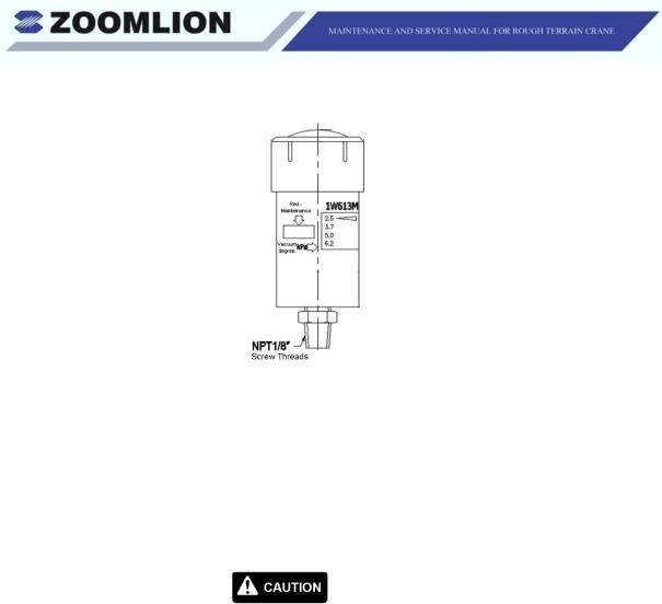
Figure 1-3 |
Indicator |
(b)A vacuum actuated indicator (See Figure 1-3) is attached on the side of the air filter assembly. Its gives you an indication of restricted airflow through the air filter. The quantity of airflow shows on the indicator at three different levels. When the light is in the green area, the air filter is good. If the light is in the yellow area, you need to clean or replace the filter cartridge. If the light is in red area, do not operate the engine. Replace or clean the filter cartridge. Examine the intake screen and cartridge area.Make sure that they are clean.
When you use a degreasing agent to clean the engine, make sure that you put a protective material around the vacuum actuated indicator (filter minder). The polycarbonate base of the engine degreasing solvents can damage or destroy the indicator.
(c)Reset the air cleaner indicator each time after the filter element is replaced to assure proper function.
(d)After you do the servicing on the air filter assembly, reset the indicator.
(5)Engine Belts
(a)Examine the engine belts for condition and correct adjustment. Refer to the Engine Manufacturer’s Manual for the belt tension and the correct procedure to make the belts tight.
Edition 2 |
Chapter 1 |
Page 1-6 |
Dec /2013 |
Maintenance |
|

B.Quarterly Inspection
(1)Fuel Tank
(a)Drain the collected water and sediment from the fuel tank.
∙Remove the drain plug and let the tank drain.
∙Stop the flow when the fuel is clear of water and sediment.
(b)If the tank has a large quantity of sediment, do the task that follows:
∙Fully drain the tank.
∙Flush the tank with kerosene until you remove all the sediment.
∙Fully drain the kerosene and refuel the tank.
C.Semi-Annually Inspection
(1)Crankcase Breather
To do servicing on the crankcase breather, follow the procedure in the
Engine Manufacturer’s Manual.
1.5ENGINE RADIATOR MAINTENANCE
A.Daily / 8 Hours:
(1)Coolant Level
(a)Insert the engine radiator coolant level and add coolant to adjust the level. You can see the level of coolant in the sight gauge near the top of the radiator tank. A solution of 50% ethylene glycol by volume is the recommended year-round coolant mixture. If necessary, refill the corrosion inhibitor. Refer to the engine manual or the servicing facility to pick the correct coolant and corrosion inhibitor.
(b)If you operate in an area that does not freeze, use a solution of clean water with a corrosion inhibitor. This gives you the best performance.
Edition 2 |
Chapter 1 |
Page 1-7 |
Dec /2013 |
Maintenance |
|

B.Monthly / 160 Hours:
(1)Radiator Exterior
Clean the radiator fins and through-core cooling passages. Use compressed air and water in the opposite direction of usual air flow to push the unwanted material out of the radiator core.
C.Quarterly:
(1)Corrosion Inhibitor
Adjust the cooling system corrosion inhibitor to the correct level after 500 hours of operation.
Do not use a chromate based corrosion inhibitor when the coolant in the system contains ethylene glycol. Only use non-chromate based inhibitors. The chromate base inhibitorreacts with ethylene glycol to make hydroxide. This you know as Green Slime. The slime decreases the heat movement rate and can cause the engine to be too hot.
D.Semi-Annually:
(1)Cooling System
Clean the cooling systemat 1000 hours or semi-annually whichevercomes first. Use a radiator cleaning compound and follow the instructions on the container. Flush the system with clean water and fill it with an ethylene glycol solution of 50% by volume.
1.6TRANSMISSION MAINTENANCE
A.Daily Maintenance Check
(1)Before you move the crane, make sure that the level of oil in the transmission is correct.
(2)Start the engine and let it idle at 1000 to 1500 rpm until the transmission increases to a temperature of 180° F to 200° F (82.2° C to 93.3° C). When the engine is at the correct temperature, slowly move the shift lever through all the gear positions. This moves oil to all parts of the system. Set the shift lever to the neutral position and set the engine speed at idle rpm.
Edition 2 |
Chapter 1 |
Page 1-8 |
Dec /2013 |
Maintenance |
|
B.Service the Transmission After Overhaul
When you service the crane for the first time after vehicle installation and / or after repair, fill the unit as follows:
(1)Fill the transmission with recommended lubricant.
(2)Start the engine and set the speed at idle to let oil fill the torque converter and lines. Stop the engine after 3 minutes.
(3)Adjust the level of transmission oil as follows:
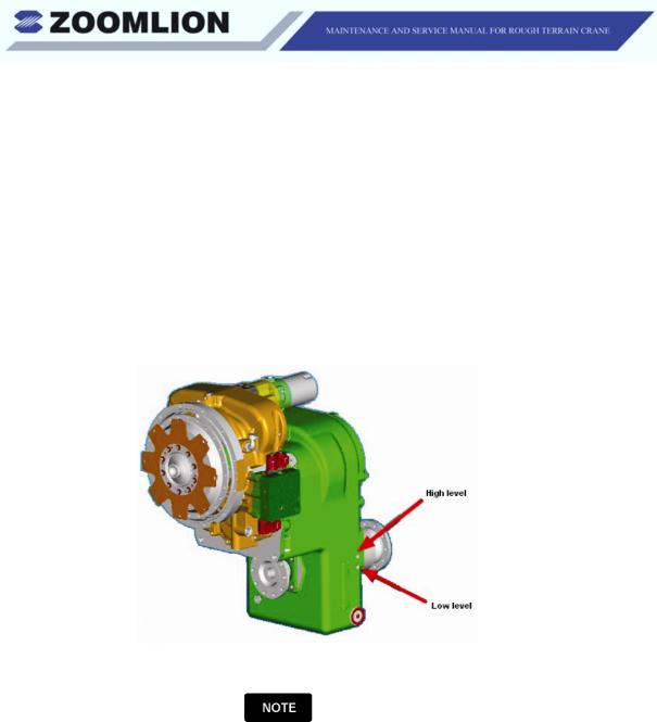
(a)Find and remove the oil level plugs on the lower part of the transmission case on the right side of the crane.
Figure 1-4 Low and High Level Plugs
There are two taper pipe thread oil level holes. One is the low level plug and the other one is the full level plug.
(b)Add the transmission oil until it flows out of the low level plug hole.
(c)Start the engine at idle speed to let the oil flow through the torque converter, oil cooler and lines. Check the oil level. Add transmission oil until it flows out of the low level plug. Install the low level plug.
(d)Let the oil temperature increase to between 180° F and 200° F (82.2° C and 93.3° C). Add oil until it flows out of the full level plug. Install the full level plug.
Edition 2 |
Chapter 1 |
Page 1-9 |
Dec /2013 |
Maintenance |
|

(e)Always do the transmission oil level checks with the speed of the engine at idle. The transmission must be in the neutral position and the transmission temperature between 180° F and 200° F (82.2° C and 93.3° C).
(4)Do not put too much fluid in the transmission!
C.Lubricant and Filter Change Interval
(1)Refer to Section 1.13 for the lubrication schedule.
(2)Use the Dana-Clark Filter.
(3)Change the hydraulic transmission oil and filter after the first 50 hours of transmission operation. After the first transmission oil and filter change, the change interval is 500 hours or 3 months of operation. Change the lubricant at the 1000 hours or 6 months of operation point.
When you operate in cold weather areas or at the initial startup, the transmission oil is cold and thick. This can cause the oil to intermittently bypass the filter.
1.7AXLE MAINTENANCE CHECK A. Monthly
(1)Examine the wheel end oil level as follows:
(a)Move each wheel until the planet gear cover is at the position in Figure 1-5. The arrow on the planet gear cover points horizontally when the cover is at the correct position. Make sure that the oil is at the correct level.
|
Figure 1-5 Wheel End |
|
Edition 2 |
Chapter 1 |
Page 1-10 |
Dec /2013 |
Maintenance |
|
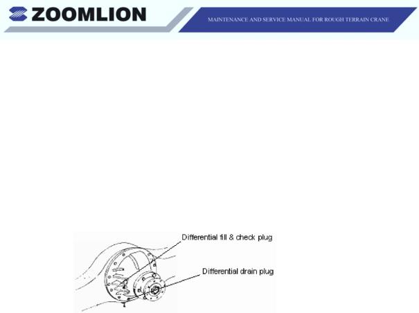
(b)Check the differential oil level by removing the filler and check plug indicated in Figure 1-6. Add oil as necessary to bring the oil level to the bottom of the hole.
(2)Do a check of the level of differential oil as follows:
(a)Remove the fill plug.
(b)Make sure that you can see oil at the bottom of the plug hole.
(c)If necessary, add oil until it comes out of the fill plug hole.
(d)Install the fill plug.
Figure 1-6 Differential Plugs
B.Annually
(1)Remove and replace the oil in the differential as follows:
(a)Remove the fill plug and the check plug to drain the oil. Refer to Figure 1-6.
(b)Make sure that you can see oil at the bottom of the plug hole.
(c)If necessary, add oil until it comes out of the fill plug hole.
(d)Install the fill plug.
1.8TIRE MAINTENANCE CHECK
A.Weekly
(1)Examine the tires and rims for the items that follow:
(a)Damage
(b)Cuts and bruises
(c)Cracks
Edition 2 |
Chapter 1 |
Page 1-11 |
Dec /2013 |
Maintenance |
|

(d)Punctures
(e)Abrasion.
(2)If necessary, make sure that you repair these items.
(3)Replace or repair the wheels if they are bent, contain a crack or are loose.
(4)Make sure that the wheel nuts are correctly tightened.
B.Tire Pressures
(1)Always keep the correct tire pressure in all the tires.
(2)Friction makes heat that increases the pressure in the tires when you move the crane. Movement at high speeds also increases the pressures in the tires. Do not deflate the tires if these conditions occur. Decrease your speed or stop until the pressure decreases.
(3)Always use an accurate tire pressure gauge. You must measure the tire pressure when the tires are cool. Do a check of the pressures at regular intervals.
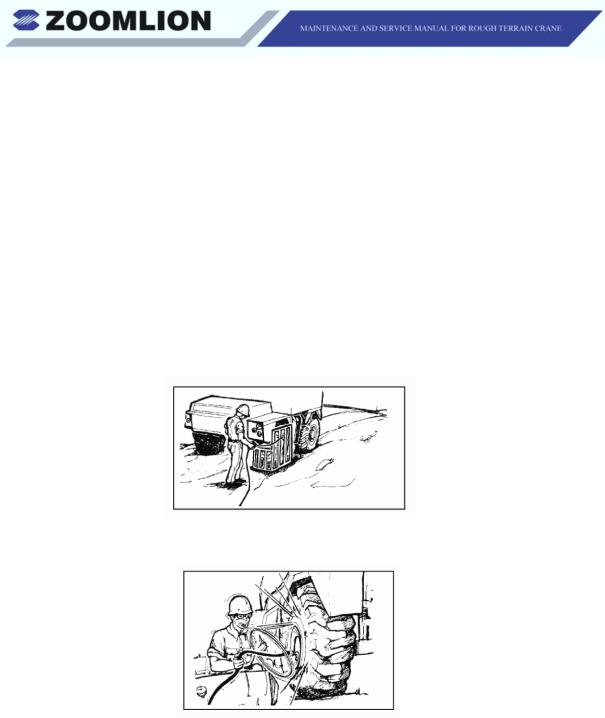
Because of the explosive nature (high temperature and high pressure) of the tire and rim it is dangerous to change a tire if you are not trained. Death or personal injury can occur while you touch or do the maintenance work on these tires. You must follow special procedures and use special tools to safely change the tires. If it is possible, let your repair company do this work. If you must change a tire, follow the step by step instructions in a Tire Repair Manual. If you must add air because of low pressure, do not be adjacent to the tire tread. Use a long extension hose to be behind the tire tread. Always use a tire cage or equivalent protection when you add air.
(4)Do not deflate air from a hot tire. The pressure lowers but the temperature increases when the tire continues to move. This increase in temperature causes the tire to malfunction.
Edition 2 |
Chapter 1 |
Page 1-12 |
Dec /2013 |
Maintenance |
|
(5)Under Inflation
The tires that do not have a sufficient quantity of pressure in them cause them to wipe and scuff over the road. Strain on the tire increases the chance to bruise.
(6)Correct Inflation
When the tires have the correct pressure in them, they do not wear too quickly.
(7)Over Inflation
When the tires have too much pressure in them, they do not touch the surface of the ground correctly. When this occurs, the tires touch the ground on the crown of the tires and quickly wear in the middle.
Figure 1-7 Correct Way
Figure 1-8 Wrong Way
Edition 2 |
Chapter 1 |
Page 1-13 |
Dec /2013 |
Maintenance |
|
 Loading...