


HC4900 Load Moment Indicator
User Manual
Edition 5 / July, 2014
For Zoomlion RT Crane
With 4-section boom

Copyright
©2010 by Hirschmann Electronics Shanghai Co., Ltd
This document contains propriety information which is protected by copyright law. All rights reserved. The manual may not be copied, reproduced or translated into another language, neither whole nor in part, without advance written authorization from Hirschmann.
Edition 5 on July 2014
Reproductions must abide by the copyright law.
Declaration
The manufacturer reserves the right to modify the contents of this manual without notice.
Hirschmann offers no guarantee whatsoever for this material, including guarantees with reference to commercial availability and suitability for particular applications.
Hirschmann shall not be liable for errors contained herein or for identical or consequential damages in connection with the furnishing, performance, or use of this manual.
Hirschmann Electronics Shanghai Co., Ltd
Suite 10K, Huamin Empire Plaza, No.728, West Yan An Road, Shanghai, P.R.China Tel: 021-51082780
Fax: 021-52375899 Zip code: 200050
Website: http://www.hirschmann-ac.com

Catalogue
1. GENERAL INFORMATION ................................................................................ |
1 |
|
2. WARNING ...................................................................................................... |
2 |
|
3. SYSTEM CONFIGURATION............................................................................... |
3 |
|
3.1 HC4900 CONTROLLER................................................................................... |
4 |
|
3.2 IC4600 CONSOLE......................................................................................... |
4 |
|
3.3 DAVS PRESSURE TRANSDUCER......................................................................... |
5 |
|
3.3.1 Technical data ................................................................................ |
5 |
|
3.3.2 Installation..................................................................................... |
5 |
|
3.4 LWG208 LENGTH/ANGLE SENSOR.......................................................... |
6 |
|
3.4.1 Technical data ................................................................................ |
6 |
|
3.4.2 Installation..................................................................................... |
6 |
|
3.5 ANTI-TWO BLOCK SWITCH....................................................................... |
8 |
|
3.5.1 Technical data............................................................................ |
8 |
|
3.5.2 Installation.................................................................................. |
9 |
|
4 OPERATION AND DISPLAY INTERFACE.......................................................... |
10 |
|
4.1 DATA DISPLAY INTERFACE VALUES ARE NOT REAL ........................... |
11 |
|
4.2 UTILIZATION DISPLAY (BAR GRAPH) ....................................................... |
13 |
|
4.3 INDICATOR LIGHT................................................................................... |
13 |
|

5. OPERATION METHOD .................................................................................... |
15 |
5.1FUNCTION SETTING ................................................................................. |
16 |
5.2 OM SETUP............................................................................................. |
16 |
5.3 REEVING SETUP .................................................................................... |
19 |
5.4 ERRO CODE REFERENCE TABLE ........................................................... |
20 |
5.5 BUZZER STOPPING................................................................................. |
21 |
6. LMI SYSTEM FUNCTIONS ............................................................................... |
23 |
6.1 WARNING .............................................................................................. |
23 |
6.2 PROHIBITION ......................................................................................... |
23 |
7 DAILY MAINTENANCE AND CALIBRATIONS ...................................................... |
24 |
7.1 MAINTENANCE CONTENT........................................................................ |
24 |
7.2 LENGTH SENSOR ADJUSTMENT .............................................................. |
24 |
7.3 ANGLE SENSOR ADJUSTMENT ................................................................ |
25 |
7.4 BUZZER ALARMING................................................................................ |
25 |
7.5 LENGTH CABLE RETRACT UN-SMOOTHLY ............................................... |
26 |
7.6 QUESTION AND ANSWER ....................................................................... |
26 |
8. HINTS AND TROUBLE SHOOTING ................................................................... |
28 |
9. HC4900 CONNECTING DIAGRAM ................................................................... |
34 |
10. OM LIST ...................................................................................................... |
35 |

1. GENERAL INFORMATION
HC4900 Load Moment Indicator (LMI) provides effective information to operators, which will assist an operator maintain a machine to work within its design parameters. LMI provides the operator with the information of the length and angle of the boom, tip height, working radius, rated load and the actual load weight and so on.
Using various sensing devices, the load moment indicator monitors machine’s various operational functions and provides the operator with a continuous reading of the machine’s capacity. The readings change continuously in response to the different operations of the machine.
If forbidden conditions are approached, the HC4900 Load Moment Indicator will warn the operator by sounding an audible alarm, lighting a warning light and locking out those functions that may aggravate the machine’s condition.
This user manual is used for Zoomlion RT crane with a 4-section boom.
- 1 -
2. WARNING
The LMI control system is used to assist in the safe operation of the crane by warning crane operator of approaching overload conditions and of over-hoist conditions that could cause damage to equipment and personnel.
The device is not, and shall not, be a substitute for good operator judgment, experience and use of accepted safe machine operating procedures.
Caution
Safe operation is the responsibility for every machine operator. Every machine operator must ensure that they read all warnings and instructions carefully and fully understand the contents. Correct operation depends on daily careful checking and serious study of the Manual.
Warning
The LMI is not able to provide aid to the machine operator unless it has been properly adjusted and unless the correct load capacity chart and the correct operating code have been entered for the respective rigging configuration. The correctness of the LMI setups must be ensured before beginning machine work in order to avoid damage to property and severe or even fatal injuries to personnel
Warning
If the LMI fails or is not functioning properly, stop the operation of the crane immediately and contact an expert service engineer. Hirschmann Electronics Co., Ltd. does not assume any responsibility for undesirable consequences resulting from continued use of the crane if the LMI is not
functioning!
Caution
Hirschmann Electronics Co.,Ltd. shall not be liable for damages caused by welding crane without power off the controller.
Hirschmann Electronics Co.,Ltd. shall not be liable for damages caused by power on the controller at a thunderstorm weather.
- 2 -
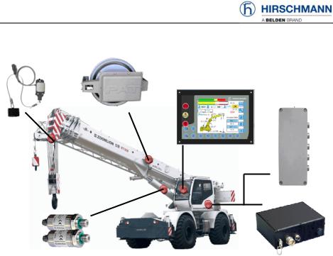
3. SYSTEM CONFIGURATION
Cable connection
HC4900 LMI System configuration
HC4900 LMI system comprises a HC 4900 central unit with an IC 4600 console together with various sensors to record the measured values.
The system operates on the principle of reference/real comparison. The actual value is compared with the calculated reference values and evaluated by the system. An overload warning signal is triggered on the display and operating console once limit values are reached. All machine movements that increase the load moment are switched off at the same time.
The crane-specific data specified by the manufacturer, such as load capacity charts, boom weights, centers of gravity and dimensions, are stored in the central data memory. This data is the reference information used to calculate the operating conditions. The boom angle and length is measured by means of length and angle sensors that are mounted on the boom. The crane load is determined indirectly with the aid of pressure transducers.
- 3 -

3.1 HC4900 Controller
HC4900 controller features high-performance, precise and limiting load moment function in harsh environment.
|
Technical data |
|
|
|
|
System clock: 40MHz |
|
|
|
|
Program memory: 16MB Flash |
|||
|
Protection class: IP65 |
|
|
|
|
Communication interface: |
|
|
|
|
1×CANopen1×RS232 |
|
|
|
|
Operating voltage: 12V 30VDC |
|||
|
Operating temperature: -20 |
° |
C |
|
HC4900 controller dimension |
+70 C |
|
|
|
Storing temperature:° |
-30 C +80 C |
|||
|
|
° |
° |
|
3.2 IC4600 Console
IC 4600 monochrome console is designed for outdoor construction vehicles and mobile machinery. It complies with international standards for environmental testing, EMC testing, and CE certification. Its easy programming, convenient online debugging, and rich paint library functions (point, line, arc, rectangle, progress bar, virtual instrument panel, such as function) help you to more efficiently understand and utilize the LMI system.
Technical data:
Operating voltage: 12 36VDC Operating temperature: -20°C +70°C Storing temperature: -30°C +80°C Resolution: 320*240(monochrome) Communication interface: 1×RS232, 1×CANopen
Protection class: Front IP65 Back IP44
IC4600 Console dimension
- 4 -

3.3 DAVS Pressure transducer
DAVS pressure transducers measure high static and dynamic pressure values of liquids or gases in rough operating environment. Measurement precision is maintained even during continuous operation at extremely dynamic pressure. The oil pressure transducer comes with a pressure connector with standardized G1/4 thread or other hydraulic connectors.
3.3.1 Technical data
Operating voltage: 8 32VDC Signal: CANopen
Operating temperature:-40°C +85°C Storing temperature: -40°C +100°C Protection class: IP67
Life expectancy: 10 million cycles Hysteresis tolerance: ±0.1%FS max.
3.3.2 Installation
Please notice the location of hydraulic piping and valve when installing the pressure transducer. By thread connection (such as follow graph), screw the pressure transducer in the hydraulic piping or seat of the balancing valves or hydraulic valves. Add the appropriate seal to the display to prevent oil leakage. Guarantee the installation position is safe and easy for cable connecting. Make sure the pressure sensor and hydraulic adaptor connect tightly. The tightening moment of G1/4 connector is 20Nm
Pressure transducer installation |
connector pin assignment |
- 5 -

3.4 LWG208 Length/Angle sensor
LWG series Length/Angle sensor can be directly installed and can precisely measure the angle and the length of boom with largest measurement length of fifty meters. The sealed housing protects the inside components from water inclusion, humidity etc.
3.4.1 Technical data
Operating voltage: 15 30VDC Operating temperature: -25°C
+75°C
Storing temperature: -40°C
+80°C
Protection class: IP65 Linearity tolerance: ±0.2° Resolution: ±0.1°
Hysteresis tolerance: ±0.1°
LWG208 Length/angle sensor dimension
3.4.2 Installation
Length/Angle sensor is installed on the main boom. Manufacturers can fix the bracket of the sensor to the crane boom by welding tap blocks and bolting it in place. When installing the sensor, the position shall be well considered, generally along the foot points of boom to the top direction. The sensor (left type) is typically installed on the left of the boom (aligned with the cab) to leave room for the fly (jib) on the right side of the boom. The sensor can be located on the right side as required. The cover can be turned 180° to put the PAT name facing upward.
- 6 -
A |
Bracket |
LWG208 Length/angle sensor installation
Length/Angle sensor consists of housing, a spring-loaded cable drum with measuring cable and mounting equipment.
Make the boom horizontal. Make sure the sensor is parallel with the main boom and the bracket is straight before fixing the bracket by bolts.
Make sure there are at least two turns measuring cable in the drum when the cable is pulled out. The recommended length of the cable = effective needed measure length + two turns cable+ about 1 meter cable for connection.
The cable drum of the sensor must rotate following the direction of the cable being pulled out. Rotate the cable drum 4 to 5 turns to pre-tighten the drum and then pull out the cable to the tip of the boom for connection.
Use the guiding wheel to keep the measuring cable at the same level. Place guiding wheels so as to prevent cable deflection, which will result in
the cable being difficult to pull out and to retract smoothly:
oMake sure the first guiding wheel A is in front of the sensor center 1.5m 2m. Ensure the guiding wheel turn width is slightly less than or equal to the cable drum turn width.
oMake sure the center of the cable guiding wheel A and other wheels are in alignment and also parallel with the main boom.
The measuring cable should be fixed to the tip of the boom tightly and the fixed point should be at the same level with the sensor center to guarantee
-7 -

the cable is parallel with the boom.
The Length/Angle sensor sometimes needs to be adjusted. Press the cable drum line to make the cable drum plane parallel with the boom plane. Rotate the cable drum and observe until the swing get smaller amplitude. If the cable drum swing too much because of the shape distortion and can’t be adjust, please stop the installation and repair or replace the Length/Angle sensor.
Make sure the spring force of the measuring cable is sufficient and the cable drum is rotating smoothly after installation is completed.
If the measuring cable is already at the pre-tighten length when boom is retracted, the pre-tighten turns can be reduced.
3.5 Anti-two Block Switch
Anti-Two Block Switch is a normally open limit switch for winches, lifting devices and cranes. It is a simple, direct installation and compact design. The sealed housing protects the inside components from water inclusion, humidity etc.
3.5.1 Technical data
Operating voltage: |
15 30V |
Operating voltage: |
-25V +70V |
Storing temperature: -40 +70 |
|
Protection class: |
IP67 |
Life expectancy: |
5×10⁶ times |
Housing: |
aluminum |
Weight: |
1.2kg |
A2B Switch dimension
- 8 -
 Loading...