


 ZOOMLION
Mobile Crane Branch Company
QUY260 Load Moment Indicator
User Manual
 Hirschmann Electronics Shanghai Co.,Ltd
Apr. 2009

User Manual
2009 by Hirschmann Electronics Co.,Ltd.
Copyright
Any reproduction, modification and translation, without official authorization in writing of Hirschmann Electronics (Shanghai) Co.,Ltd, shall be prohibited. For reproduction of this manual please refer to
Copyright Law.
1st edition on Apr. 2009
Guarantee
The information in this document is subject to change without notice. Hirschmann makes no warranty of any kind with regard to this material, including, but not limited to the implied warranties of merchantability and fitness for a particular purpose. Hirschmann shall not be liable for errors contained herein or for incidental or consequential damages in connection with the furnishing, performance, or use of this manual.
Hirschmann Electronics Shanghai Co.,Ltd
Suite 10K, Huamin Empire Plaza, No.728, West Yan An Road, Shanghai, P.R.China
Tel 021-51082780
Fax 021-52375899
Zipcode 200050
Website http://www.hirschmann-ac.com

|
User Manual |
|
Index |
1.Breif introduction................................................................................................................................. |
2 |
2.General information............................................................................................................................. |
2 |
3.Warnings............................................................................................................................................... |
2 |
4.System configuration............................................................................................................................ |
3 |
4.1Controller...................................................................................................................................... |
3 |
4.2 Console ......................................................................................................................................... |
4 |
4.3 KMD Force sensor ...................................................................................................................... |
4 |
4.4 Angle sensor................................................................................................................................. |
4 |
5. System introduction ............................................................................................................................ |
5 |
5.1 OM icon........................................................................................................................................ |
6 |
5.2 Main interface.............................................................................................................................. |
7 |
5.3 Function key................................................................................................................................. |
8 |
5.3.1 OM & Reeving setting........................................................................................................ |
9 |
5.3.2 I/O Port checking ............................................................................................................. |
12 |
5.3.3 System setting ................................................................................................................... |
14 |
5.3.4 CAN-bus checking............................................................................................................ |
16 |
5.3.5 Angle limitation & Time setting...................................................................................... |
17 |
6. Trouble shooting................................................................................................................................ |
19 |
7. System connection ............................................................................................................................. |
25 |
1

User Manual
1.Breif introduction
This manual is made for the crawler cranesQUY260 of Zoomlion. Please read the manual carefully according the collocation of different types.
2.General information
The Hirschmann load moment indicator (LMI) iFLEX5 has been designed to provide the crane operator with the essential information required to operate the machine within its design parameters. Using various sensing devices, the Load Moment Indicator monitors various crane function and provide the operator with a continuous reading of the load capacity. The readings continuously change as the crane moves and lifts. The LMI provides the operator with information regarding the length and angle of the boom, tip height, working radius, rated load and total weight of actual lift.
If non-permitted condition is approached, the iFLEX5 Load Moment Indicator will warn the operator by sounding an audible alarm, lighting a warning light and cutting off those functions that may aggravate the crane’s condition.
3.Warnings
The LMI is an operational aid that warns a crane operator from approaching conditions of overloading and over-hoisting which would cause great damage to the equipment and personnel.
The LMI could only prevent overload of the crane boom in lengthwise vertical level but could not prevent accidents caused by inclined hoisting, wind loading, inclination or foundering of the road and rail or driving oversteps. So the operators and other people shall not ignore safe management and operating procedures of the crane because of the existence of the device. It is not, and shall not, substitute for a good operator’s judgment, great experience or standard operating procedures. The responsibility for the safe crane operation shall remain with the crane operator who shall ensure that all warnings and instructions supplied are fully understood and observed.
Prior to operating the crane, the operator must carefully and thoroughly read and understand the information in this manual to ensure that he knows the operation and limitations of indicator and crane.
Notice The LMI can only work correctly, if all adjustments have been properly set. For correct adjustment, the operator has to answer thoroughly and correctly all questions asked during the setup procedure in accordance with the real rigging state of the crane. To prevent material damage and serious or even fatal accidents, the correct adjustment of the LMI has to be ensured before starting the crane operation.
2
User Manual
4.System configuration
4.1 System configuration
4.1 Controller
4.2 Controller
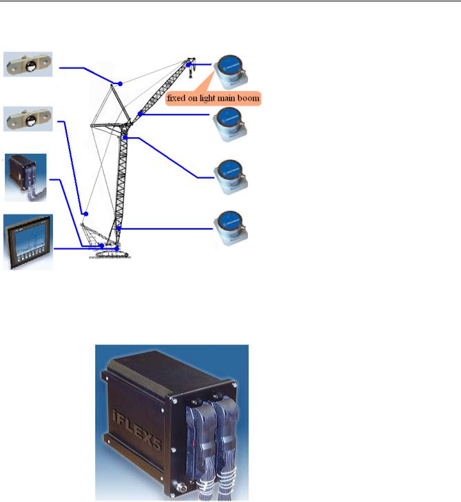
The system is composed of Expert console, iFLEX5 controller, KMD force sensor, angle sensor, etc.
When operator sets current OM and reeving according to the key of the display, the signal is transmitted to controller and display by pull sensor. The display shows the actual weight and rated weight. The actual weight and rated weight is compared in the controller. Once the rated weight is reached, the controller will indicate the overloading warning signal and send warning sound. At this moment, operator is forbidden to operate to dangerous direction.
Controller: 32 digit industrial control PLC system and high-powered processor qualify the requirements of bad environment for all kinds of industrial system. IFLEX5 module is composed of base board or base board add expansion board. Customers could choose different IFLEX5 module according to their own needs. Each module can be connected by CANBUS. Due to the building block mode, the IFLEX5 is not only applicable to medium and small control systems, but also to big and complicated control systems.
3
User Manual
4.2 Console
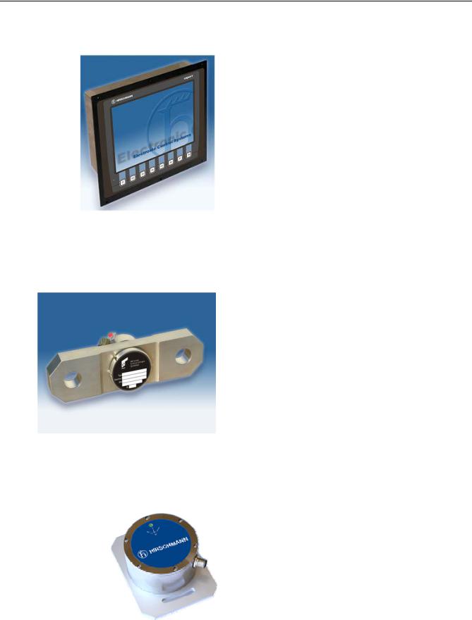
Console: a 640*480 color LCD of industrial lattice screen graph liquid crystal. It can display all the operational data that you are concerned. The combination between the Graphical display and Genersys software achieve the on-line program for graph. The strong graph compiled capability is incomparable with other Industrial Control displays.
4.3 Console
4.3 KMD Force sensor
The system adopts shock-proof, anti-electromagnetic interference, and high precision and low zero drift. As the sensor has the compensated function of temperature, it can retain its own quality even with continuous and high-intensive operation.
Remarks all the analog sensor for iFLEX5 system must be current type or with CAN-bus. Voltage sensor have to change to current sensor.
4.4 KMD force sensor
4.4 Angle sensor
The WGC angle sensor is for exact measurement for angle of all kinds of construction machines. Distinguished by its compact exterior, the sensor has the feature of simple installation, high efficiency and accuracy, no hysteresis, high protective class, long time service life and suited
to extreme ambient condition.
4.5 Angle sensor
4

User Manual
5. System introduction
When the iFLEX5 control system is power on, the console will display QUY260 crawler crane as below:
5.1 Welcoming interface
After 4 5 seconds, main interface—the LMI interface will present as below:
5.2 LMI main interface
At 5.2, from the top to the bottom is
Part 1: Operate State column; Part 2:main interface: Part 3: function key column
5

User Manual
5.1 OM icon
Operators could learn present crane state through the working mode icon on top part of the console.
A.Error code icon
To indicate which part of the LMI is abnormal. Operators then can remove difficulties accordingly, and the LMI will back to normal condition.
B.Reeving icon
To display present reeving.
C.OM code icon
To display current OM code.
D.CAN-bus mode icon
To display the CAN communication mode between the console and the controller. When the light is on, the CAN communication is abnormal.
E.A2B alarming icon
This means the hook is reaching to the ultimate height, operators shall stop movement of the hook right away.
F.Pre-warning icon
This means the moment percentage is over 90 , operators shall be awared of that.
G.Stop movement icon
This means the movement of the crane is very dangerous, operators shall back to the safe side. Or the LMI is abnormal, the problem shall be solved immediately.
H.Time display icon
To display the local time.
6

User Manual
5.2 Main interface
5.3 Presenting main interface
OM introduction Main boom length jib length Installed angle of the fixed jib Mode display
operating heightmain boom angleoperating radius
Still presenting luffing jib angle at luffing jib OM
Moment percentage barcode |
Moment percentage value |
Actual load capacity |
Rated load capacity |
LMI Operate State display presenting normal OM or error code information and trouble shooting when it is abnormal
Notice when operating the crane operators shall observe changes of the aboved datas at this interface
7
 Loading...