

Page 1

ADSL Modem
U S E R ’ S M A N U A L
X5
Page 2

NOTICE
NOTICE
NOTICENOTICE
This document contains proprietary information protected by copyright, and
this Manual and all the accompanying hardware, software, and
documentation are copyrighted. No part of this document may be
photocopied or reproduced by mechanical, electronic, or other means in
any form.
The manufacturer do es not warrant that the hardwar e will work properly in
all environments and applications, and makes no warranty or representation,
either expressed or implied, with respect to the quality, performance,
merchantability, or fitness for a particular pur po s e of the software or
documentation. The manu facturer reserves the right to make changes to the
hardware, software, and documentation without obligat ion to notify an y
person or organization of the revision or change.
All brand and product names are the trademarks of their respective owners.
© Copyright 2003
All rights reserved.
Page 3

Contents
1 INSTALLATION INSTRUCTIONS ................................... 4
1.1 I
MPORTANT! BEFORE YOU BEGIN ..........................................4
ACKAGE CONTENTS.......................................................... 6
1.2 P
1.3 Q
UICK START INSTRUCTIONS............................................... 6
F YOU NEED HELP...........................................................13
1.4 I
2 ADVANCED SETUP OPTIONS....................................... 14
OW TO USE THE ADVANCED OPTIONS.................................14
2.1 H
2.2 WAN S
2.3 LAN S
2.4 NAT F
2.5 V
2.6 DMZ............................................................................25
2.7 DNS ............................................................................ 28
2.8 ADSL C
ROUTE TABLE .................................................................30
2.9
2.10 M
3 SYSTEM ADMINISTRATION........................................ 34
3.1 M
3.2 M
3.3 P
3.4 R
3.5 U
4 REMOVING THE X5 MODEM........................................ 40
ETTINGS..............................................................15
ETTINGS ...............................................................20
IREWALL...............................................................21
IRTUAL SERVER (PORT FORWARDING).................................22
ONFIGURATION.....................................................29
ISCELLANEOUS ............................................................32
ONITORING SYSTEM STATUS ............................................34
ONITORING ADSL STATUS ..............................................35
ERFORMING SYSTEM ADMINISTRATION TASKS........................37
ESETTING THE UNIT TO ITS DEFAULT SETTINGS.....................38
PDATING THE UNIT’S FIRMWARE........................................39
APPENDIX A: FRONT AND BACK PANEL DATA............... 41
APPENDIX B: ONLINE GAMING AND THE X5................. 43
SING YOUR X5 WITH XBOX® LIVE ...........................................43
U
U
SING YOUR X5 WITH PLAYSTATION
®
2.....................................44
APPENDIX C: CONFIGURING YOUR BROWSER............. 46
APPENDIX D: MACINTOSH AND LINUX USERS:
CONFIGURING TCP/IP SETTINGS................................. 50
APPENDIX E: TROUBLESHOOTING................................ 55
APPENDIX F: REGULATORY INFORMATION.................. 57
Page 4

1
Installation Instructions
1.1 Important! Before you Begin
Before installing your X5 ADSL modem, you must have DSL
service enabled on your telephone line. To do this, you need to
sign up with a DSL service provider. They will arrange to have
DSL enabled, and provide you with a User Name and Password (if
required) and the Communications Settings necessary to log on to
their network.
You will need your User Name and Password to complete the
installation, so please make sure you have them at hand.
User Name _________________________
Password _________________________
The following table lists some DSL broadband communications
settings. This table is intended for reference only. Typically you
should not need to enter this information; it should be
automatically supplied if needed as part of your service provider’s
installation procedure.
4
X5
ADSL Modem User’s Manual
Page 5

Service Provider VPI VCI Encapsulation
Belgium—ADSL Office 8 35 Routed IP over ATM LLCSNAP (RFC
Belgium—Turboline 8 35 PPPoA LLCSNAP (RFC 2364)
Denmark—Cybercity, Tiscali 0 35 PPPoA VCMUX (RFC 2364)
France (1) 8 35 PPPoA LLCSNAP (RFC 2364)
France (2) 8 67
Iceland—Islandssimi 0 35 PPPoA VCMUX (RFC 2364)
Iceland—Siminn 8 48 PPPoA VCMUX (RFC 2364)
Italy 8 35 PPPoA VCMUX (RFC 2364)
Netherlands—MX Stream 8 48 PPPoA VCMUX (RFC 2364)
Portugal 0 35 PPPoE LLCSNAP (RFC 2516)
Saudi Arabia (1) 0 33 PPPoE LLCSNAP (RFC 2516)
Saudi Arabia (2) 0 35 PPPoE LLCSNAP (RFC 2516)
Saudi Arabia (3) 0 33
Saudi Arabia (4) 0 33
Saudi Arabia (5) 0 35
Saudi Arabia (6) 0 35 Routed IP over ATM LLCSNAP (RFC
Spain—Albura, Tiscali 1 32 PPPoA VCMUX (RFC 2364)
Spain—Colt Telecom, Ola
Internet
Spain—EresMas, Retevision 8 35 PPPoA VCMUX (RFC 2364)
Spain—Telefonica (1) 8 32 PPPoE LLCSNAP (RFC 2516)
Spain—Telefonica (2),
Terra
Spain—Wanadoo (1) 8 35 PPPoA VCMUX (RFC 2364)
Spain—Wanadoo (2) 8 32 PPPoE LLCSNAP (RFC 2516)
Spain—Wanadoo (3) 8 32 Routed IP over ATM LLCSNAP (RFC
Sweden—Telia 8 35 Bridged IP over ATM VCMUX (RFC
Sweden—Telenordia 8 35 PPPoE (RFC 2516)
Switzerland 8 35 PPPoE LLCSNAP (RFC 2516)
UK (1) 0 38 PPPoA VCMUX (RFC 2364)
UK (2) 0 38 PPPoE LLCSNAP (RFC 2516)
USA 0 35 PPPoE LLCSNAP (RFC 2516)
Venezuela—CANTV 0 33
The information in this table is subject to change. If necessary, check with your
provider.
0 35 PPPoA VCMUX (RFC 2364)
8 32 Routed IP over ATM LLCSNAP (RFC
1483)
PPPoA (RFC 2364) or PPPoE (RFC
2516)
Bridged IP over ATM LLCSNAP (RFC
1483)
Routed IP over ATM LLCSNAP (RFC
1483)
Bridged IP over ATM LLCSNAP (RFC
1483)
1483)
1483)
1483)
1483)
Routed IP over ATM LLCSNAP (RFC
1483)
Chapter 1: Installation Instructions 5
Page 6

1.2 Package Contents
In addition to these installation instructions, your package includes
the following items:
• X5 ADSL unit
• Power adapter and power cord
• Straight-through Ethernet cable
• USB cable
• RJ-11 phone cord
• RJ-11-to-wall-jack adapter (certain models only)
• CD-ROM, including installation software
• Warranty and Customer Support information (on CD-ROM)
• Phone filter(s) (certain models only).
If anything is missing or damaged, please contact your supplier.
You Will Also Need
•
A Macintosh, Linux, or Windows 98/98SE/2000/Me/XP
computer equipped with a Network Interface Card (NIC) or a
Windows 98/98SE/2000/Me/XP computer equipped with a
USB port.
•
A telephone wall jack to plug the X5 unit into. The associated
phone line must be DSL enabled.
1.3 Quick Start Instructions
Your computer should be on.
Windows users:
to your computer’s Ethernet port or its USB port.
Macintosh and Linux users:
Depending on your operating system and preference, follow the
appropriate instructions below.
6
You have the option of connecting your X5 unit
You must use the Ethernet option.
X5
ADSL Modem User’s Manual
Page 7

Windows users:
Using any combination of Ethernet and USB jacks, you can
connect multiple computers to your X5 unit and share
Internet access.
Macintosh and Linux users:
You can use the X5’s four Ethernet jacks to connect multiple
computers and share Internet access.
To Connect via the Ethernet Option
Macintosh and Linux Users:
1111
You do not need to run the CD-ROM software.
Skip to Step 2 below.
Windows 98/98SE, Me, 2000, and XP Users:
Install the software before connecting the hardware.
Insert the supplied CD-ROM into your computer. The
aaaa
CD starts automatically and the
(
If the CD does not start automatically, from the
Note:
desktop, go to
where D is the letter of your CD-ROM drive.)
Start | Run
Main Menu
and then type
opens:
D:\setup.exe
,
Click the
bbbb
and then click the
installation proceeds automatically.
When the process is complete, you will be prompted to
cccc
click
connect the hardware.
Chapter 1: Installation Instructions 7
ADSL Modem Installation Wizard
Ethernet
. Your computer will shut down so you can
Finish
option. The software
button,
Page 8

All hardware connections originate from the modem’s back
2222
panel. (For reference, we have included a table that defines
these back panel ports, or jacks; see page 41.)
Plug one end of the supplied phone cord into the unit’s
aaaa
jack and the other end into the ADSL wall jack.
DSL
Plug one end of the straight-through Ethernet (10BaseT)
bbbb
cable into one of the modem’s LAN jacks (1, 2, 3, or 4)
and plug the other end into your computer’s Ethernet
port.
Plug one end of the included power adapter into the
cccc
unit’s
POWER
or wall receptacle.
Turn the unit on by pushing the
dddd
light on the unit’s front panel turns on.
PWR
jack and the other end into a power strip
ON/OFF
switch. The
Note: You can also attach the X5 to an access point,
switch, or network hub via its LAN jack(s) and thereby
connect additional computers.
If your hub has an uplink or daisy chain port, you can use
—
the supplied straight-through Ethernet cable to connect the
two.
If your hub has a numbered port or if you are using an
—
access point, you need a crossover Ethernet cable (sold
separately).
Throughout this manual, when we refer to an X5 Ethernet
connection, it should be understood that this connection may
be to a computer, access point, or hub.
The unit performs a startup sequence—the front panel
3333
light blinks. (For reference, we have included a table on page
42 that defines the X5’s front panel lights.) When the
light changes from blinking to solid, turn your computer back
on and proceed to
(page 10).
X5
8
Establishing Communication with the
X5
ADSL Modem User’s Manual
LINK
LINK
Page 9

To Connect via the USB Option
You must install the requisite USB software on your
1111
Windows computer before connecting the hardware.
Insert the supplied CD-ROM into your computer. The
aaaa
CD starts automatically and the
(
If the CD does not start automatically, from the
Note:
desktop, go to
where D is the letter of your CD-ROM drive.)
Click the
bbbb
and, if prompted, the
installation proceeds automatically. When the process is
complete, the Main Menu minimizes for future use and a
Zoom Web Console icon resides on your desktop.
Start | Run
ADSL Modem Installation Wizard
USB
Main Menu
and then type
option. The software
opens:
D:\setup.exe
button
,
Now connect the hardware. All connections originate from
2222
the X5’s back panel. (For reference, we have included a table
that defines these back panel ports, or jacks; see page 41.)
Plug one end of the included power adapter into the
aaaa
unit’s
POWER
or wall receptacle.
Turn the unit on by pushing the
bbbb
light on the unit’s front panel turns on.
PWR
Plug one end of the supplied phone cord into the unit’s
cccc
jack and the other end into the ADSL wall jack.
DSL
Plug one end of the USB cable into the modem’s
dddd
jack and plug the other end into your computer’s
corresponding USB port.
Chapter 1: Installation Instructions 9
jack and the other end into a power strip
ON/OFF
switch. The
USB
Page 10

The unit performs a startup sequence—the front panel
3333
light blinks. (For reference, we have included a table on page
42 that explains the meaning of the X5’s front panel lights.)
LINK
Note:
indicating the progression of the installation; typically no user
action is necessary. If you are using Windows XP, however,
you may be required to click
Depending on your operating system, you may see a
4444
Hardware Installation
Signature Not Found
these messages and click
Windows XP Users:
When the modem’s startup sequence is complete, the
light will change from blinking to solid. Continue below with
Establishing Communication with the X5
You may see a
Found New Hardware
.
Next
disclaimer box or a
dialog box. You can safely ignore
or
Yes
If prompted to do so, click
Continue Anyway
box
Digital
.
Establishing Communication with the X5
Depending on your computer’s operating system, you may
1111
have a Zoom Web Console icon on your desktop.
• If you do, double-click it to display the
Password
dialog box.
Network
.
Finish.
LINK
• If you do not have a Zoom Web Console icon on your
desktop, open your Web browser, type
and press Enter to display the
Note:
that your Internet settings need adjustment. Turn to page 46
for instructions.
Note:
10
If your web browser doesn’t open properly, it may be
This User Name and Network Password are different
from the ones that your service provider gave you.
They provide an added level of security that protects
your ADSL unit’s settings.
Network Password
X5
ADSL Modem User’s Manual
http://10.0.0.2
box.
Page 11
Type the following letters, the X5’s default User Name and
Password.
•
User Name=
•
Password=
Remember:
sensitive.
Tip:
If the
the following in this order:
Recheck all connections.
aaaa
Restart the modem and computer.
bbbb
Perform a “hard” reset. (See page 38.)
cccc
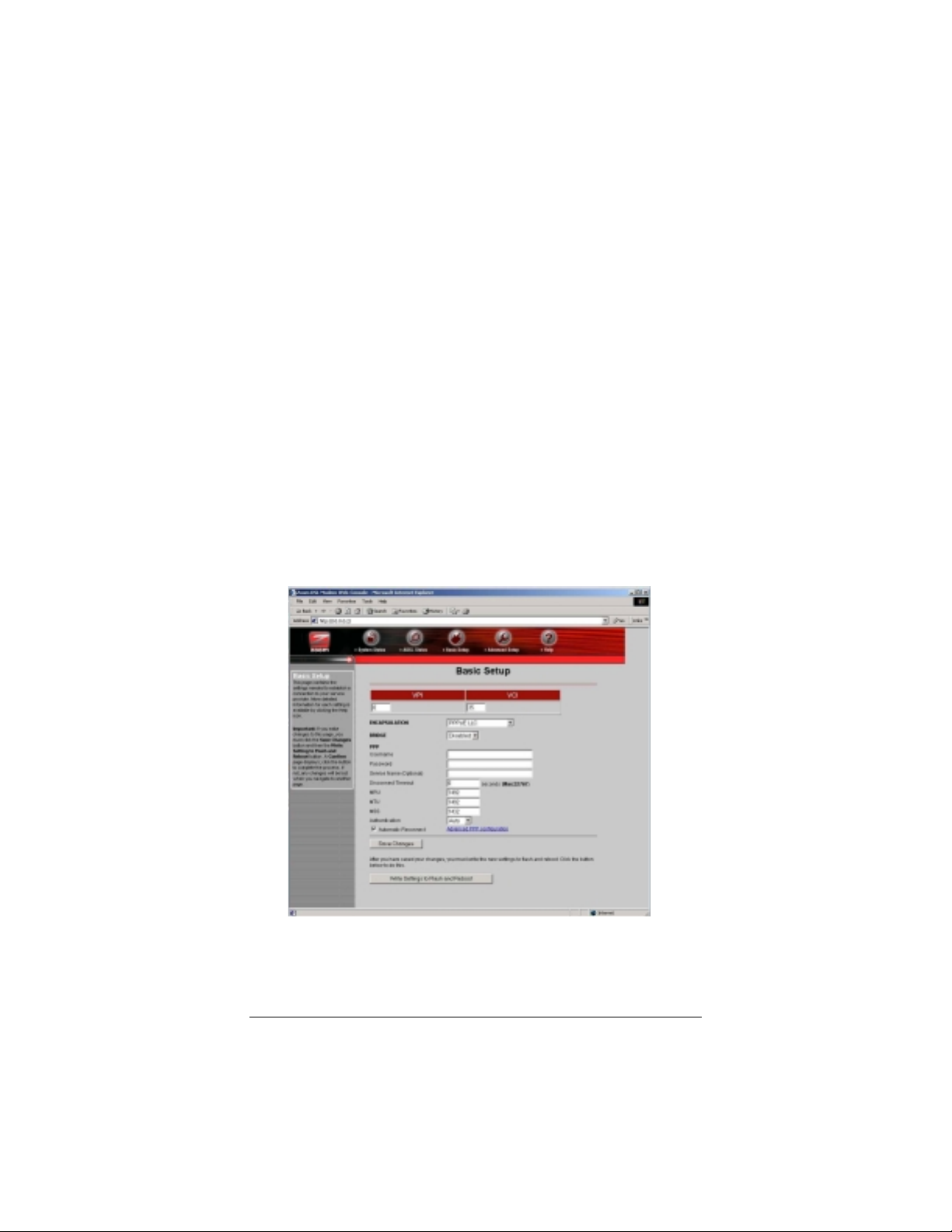
The
2222
Basic Setup
with your X5. This page provides details about your Internet
connection and includes information that the X5 uses to
automatically connect to your service provider.
admin
zoomadsl
The
User Name
Network Password
page displays. You are now communicating
and
Password
box doesn’t display, perform
letters are case-
Check that the VPI, VCI, and Encapsulation settings
aaaa
match those supplied by your service provider. (Refer to
the table on page 5 if necessary or consult your provider.)
Chapter 1: Installation Instructions 11
Page 12

Enter the login
bbbb
your service provider.
Optional: Enter a
cccc
has given you one.
Click
dddd
IMPORTANT:
Save Changes
Flash and Reboot
unit has reset itself (when the front panel’s
remains on steady again), your X5 is ready to use. You
can open another Web browser or use the one that is
already open to access the Internet.
Every time you make changes to the Basic Setup page,
you must click the
Write Settings to Flash and Reboot
Confirm
process. If not, any changes will be lost when you
navigate to another page.
User Name
Service Name
. Once the reboot is complete and the
Save Changes
page displays; click the button to complete the
and
Password
if your service provider
and then click
supplied by
Write Settings to
LINK
button and then the
button. A
light
12
X5
ADSL Modem User’s Manual
Page 13

Using Phone Filters
You should use a filter with each device—phone, fax machine,
analog modem, etc.—that is sharing the DSL-enabled line, because
this prevents the device from receiving noise when the DSL
modem is on. For all other devices on the DSL-enabled line, plug
the device’s phone cord into the filter’s
filter’s
end into the wall jack. Some X5 models come with
LINE
PHONE
end, and plug the
filters, and more can be purchased from a retailer or service
provider.
Now that your modem is installed and appropriate filters are
attached, you’re done. Enjoy using the X5.
The remainder of this manual contains information intended for
those users looking for expanded capabilities or for future
reference—for example, there are chapters on
Options
and
System Administration
. Refer to the Table of
Advanced Setup
Contents for guidance.
1.4 If You Need Help
•
If you have hardware installation problems, our Technical
Support Staff will be happy to assist you.
Windows Users:
Please see the Customer Support portion of
the CD for contact information. You may also want to refer to
the Frequently Asked Questions on the CD.
Macintosh and Linux Users:
You will find Customer
Support information and Documentation in Adobe PDF
format in the appropriately named folders in the CD-ROM’s
directory.
• If you have DSL service problems, you should contact your
DSL service provider.
Chapter 1: Installation Instructions 13
Page 14
2
Advanced Setup Options
In addition to its basic setup options, the X5 unit includes
options for specialized, or advanced, settings. If you are like
most users, you will not need these options. The X5 is designed
so that the basic setup settings are sufficient for most users.
This chapter is applicable only if you need to perform
sophisticated tasks.
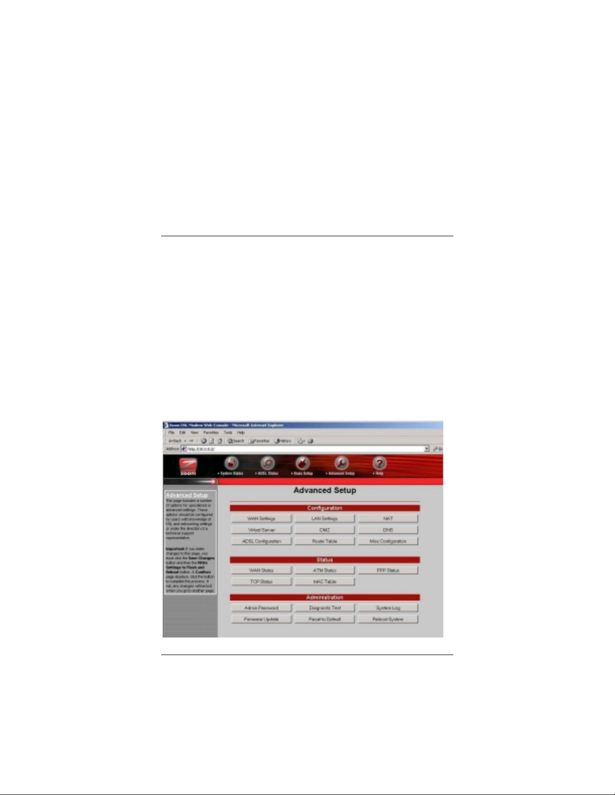
2.1 How To Use the Advanced Options
All the Advanced Configuration settings are accessible from the
Advanced Setup
interface page. (If you have exited from the X5 and have forgotten
how to establish communication with it, refer to page 10.)
page. Click its icon at the top of the X5’s main
14
X5
ADSL Modem User’s Manual
Page 15
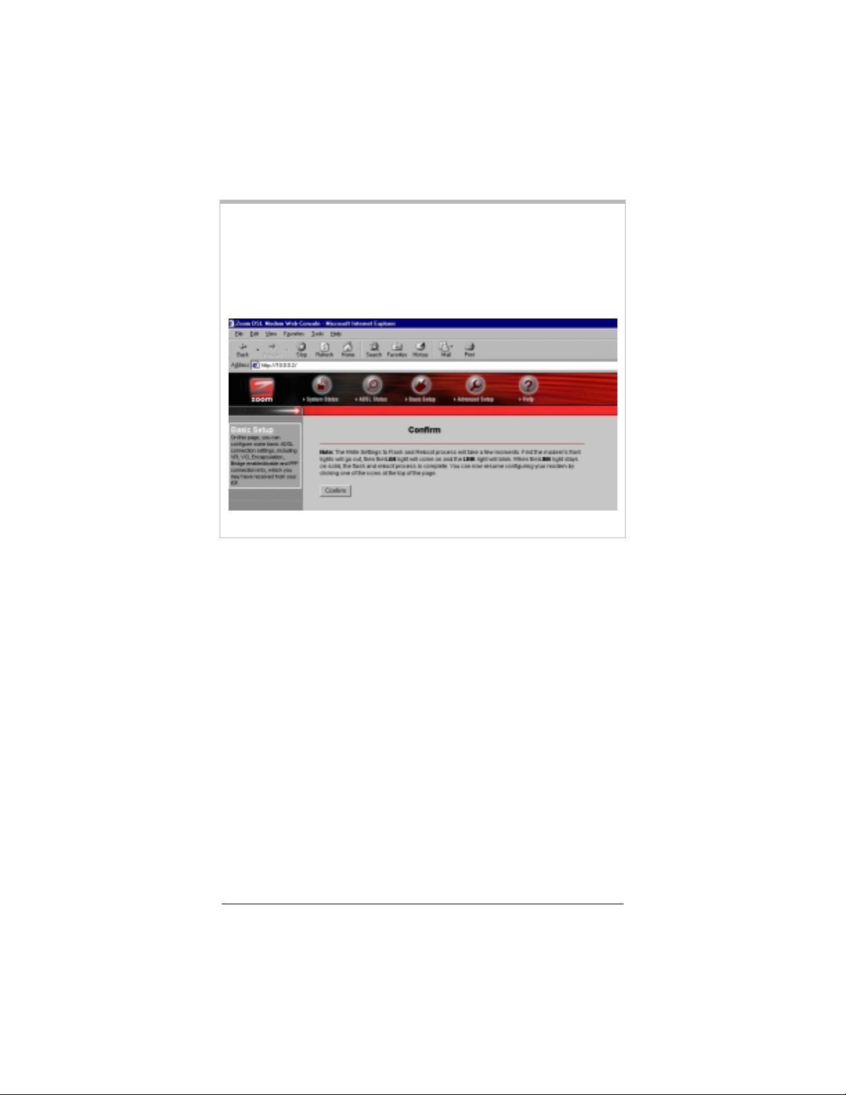
IMPORTANT:
Every time you make changes to an Advanced Setup page,
you must click the
Settings to Flash and Reboot
displays; click the button to complete the process. If not, any
changes will be lost when you navigate to another page.
Save Changes
button and then the
button. A
Confirm
page
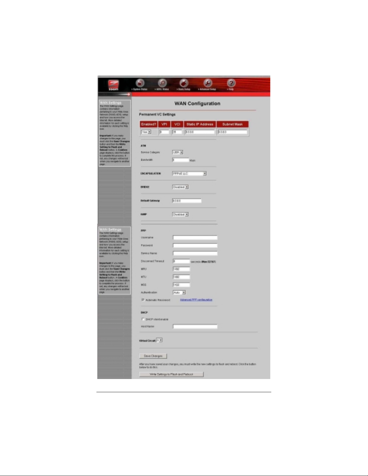
2.2 WAN Settings
The WAN Settings page contains information pertaining to your
Wide Area Network (WAN) ADSL setup and how you access the
Internet. From the
Settings
each field or category, we have included a table for reference.
Note:
reflected in the
button. A screen displays with several fields to fill in. For
Any settings entered in the
Advanced Setup
WAN Settings
page, click the
Basic Setup
page.
WAN
page will be
Write
Chapter 2: Advanced Setup Options 15
Page 16
16
X5
ADSL Modem User’s Manual
Page 17

Permanent VC (Virtual Circuit) Settings
Your service provider will supply the Permanent Virtual Circuit
(PVC) setting for your basic Internet connection. You can define
additional PVCs for services such as telephony or to connect to a
managed Virtual Private Network (VPN) if available in your area.
Consult your service provider.
Enabled?
VPI
VCI
Static IP Address
Subnet Mask
Virtual Circuits
You must scroll down to the bottom of the page to reach
Note:
the
Virtual Circuit
Enabled by default.
Supplied by your service provider (reference
table appears on page 5).
Supplied by your service provider (reference
table appears on page 5).
Most providers use dynamic IP addressing;
only providers using Bridged or Routed IP
Encapsulation can use static IP addresses. If
your provider has given you a static IP
address, enter it here.
For static IP address users only (see above):
Enter the subnet mask of the static IP
address given to you by your service provider.
No. of virtual circuits that can be set up: 1-7.
field and select a number from the dropdown
list to identify a PVC. The number 0 is reserved for the Basic Setup
settings preconfigured for your provider. Be sure to click
Changes
and then
Write Settings to Flash and Reboot
Save
. Once
you have set up multiple PVCs, you can switch between them by
selecting a different number from the
list and clicking
and Reboot
.
Save Changes
and
Writing Settings to Flash
Virtual Circuit
dropdown
ATM
ATM, or Asynchronous Transfer Mode, allows you to change the
way in which your data is sent over the Internet.
ATM Service Category
Bandwidth
Chapter 2: Advanced Setup Options 17
Default is UBR (Unspecified Bit Rate). CBR
(Constant Bit Rate) is optional. You can only
use CBR if you have arranged to do so with
your provider.
Default is 0 (which equals UBR). Specifying
bandwidth is only possible with CBR.
Page 18

Encapsulation
The
Encapsulation
specified by your service provider (see
page 17).
mode, like the VPI and VCI numbers, is
Permanent VC Settings
,
Encapsulation
This mode is supplied by your service provider
(reference table appears on page 5).
Bridge
The
Bridge
only if your service provider instructs you to.
option is disabled by default. You should enable it
IGMP (Internet Group Manageme nt Pr otocol)
IGMP is the Internet standard for IP multicasting, or broadcasting
a message to many recipients simultaneously. Your choices are
enabled
or
disabled
; the default is
disabled
.
IMPORTANT:
Before enabling IGMP, navigate to the Advanced Setup
page, click
IGMP Proxy
Misc Configuration
dropdown list, and click
Write Settings to Flash and Reboot
, select
. If you don’t
Enabled
in the
Save Changes
and
perform this step first, enabling IGMP on this page will
not have any effect.
Default Gateway
Normally, you would not enter anything into the
field. You would do so only if you want to connect your modem to
the Internet via a different Gateway Router, or if your service
provider has instructed you to change it.
Default Gateway
PPP (Point-to-Point Protocol)
PPP is the most widely used protocol for authenticating your
connection to the Internet. Should you change service providers,
you may need to change the data in these fields.
settings also appear on your
18
Basic Settings
page.
X5
ADSL Modem User’s Manual
Note:
These
Page 19

User Name
Password
Service Name
Disconnect Time
MRU*
MTU*
MSS*
Authentication
Automatic Reconnect
*You must enter your PPP User Name and Password before making changes to
these fields; otherwise they will not take effect.
Supplied by your service provider.
Supplied by your service provider.
Optional; supplied by your service provider.
ADSL connection will be dropped after the
ADSL line is idle for a certain amount of time
(measured in seconds). Select 0 to ensure
that you won’t be disconnected.
Maximum Receive Unit. Largest physical
packet size, in bytes, that a network can
accept. Any messages larger must be
fragmented. Default is 1492.
Maximum Transmission Unit. Largest
physical packet size, in bytes, that a network
can send. Any messages larger must be
fragmented. Default is 1492.
Maximum Segment Size. Largest data
segment, in bytes, allowed within each IP
packet. Default is 1432.
PPP user authentication method. Default is
Auto
; you can specify CHAP or PAP only.
Enabled by default. Check this box if you do
not want to be reconnected automatically if
the ADSL connection is terminated
unexpectedly.
DHCP (Dynamic Host Configuration Protocol)
DHCP
change your DHCP setting. Do so only if your service provider
requests it.
DHCP client enable
Host Name
Chapter 2: Advanced Setup Options 19
is disabled by default. Typically, you should not need to
Check this box only if instructed to by your
service provider.
If necessary, supplied by your service
provider.
Page 20
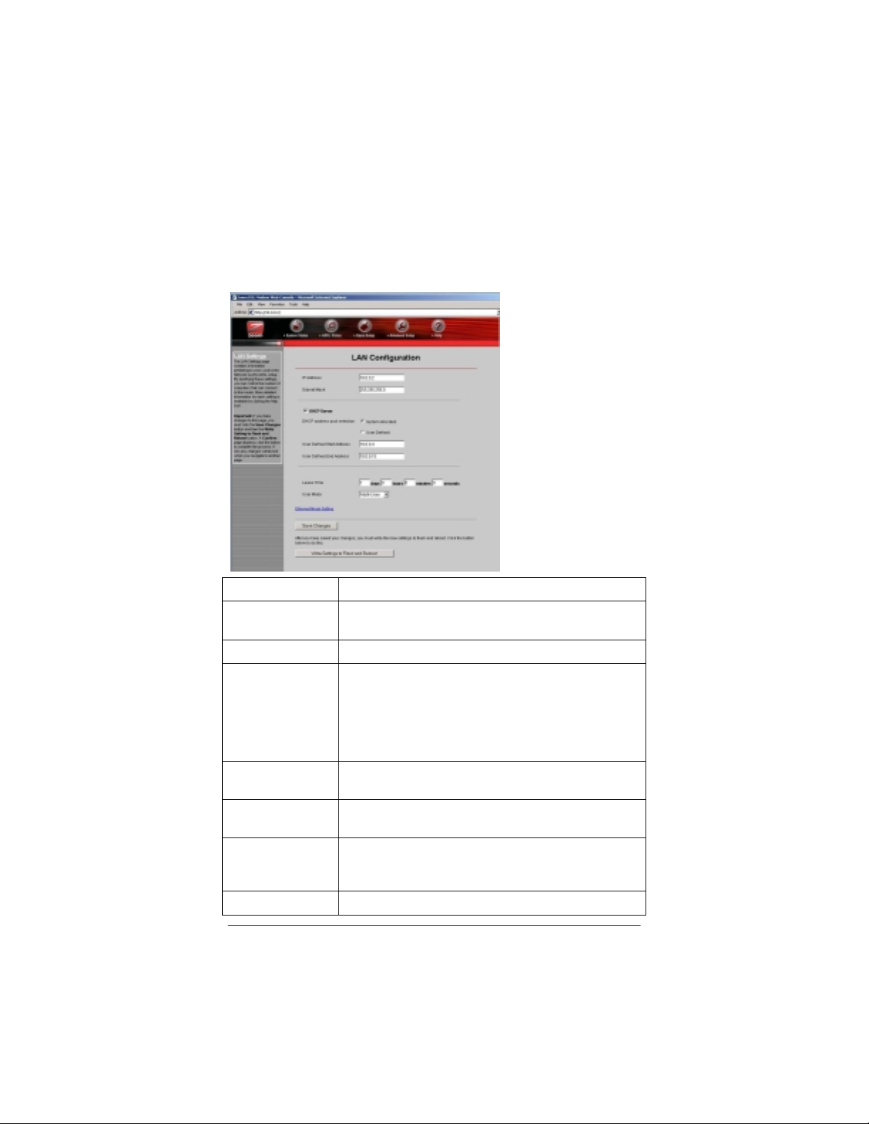
2.3 LAN Settings
By modifying your LAN ADSL setup and DHCP settings, you can
limit the number of DHCP addresses assigned by the X5. To
change your settings, from the
LAN Settings
button.
Advanced Setup
page click the
LAN IP Address
Subnet Mask
DHCP Server
DHCP Address
Pool Selection
User Defined
Start Address
User Defined
End Address
Lease Time
User Mode
20
X5’s IP address. Default is 10.0.0.2.
X5’s subnet mask address. Default is
255.255.255.0.
Enabled by default.
The DHCP Address Pool is based on the X5’s LAN
IP address plus 12 IP addresses; for ex., if you are
using the X5’s default LAN IP address of 10.0.0.2,
the DHCP Address Pool would be 10.0.0.4-
10.0.0.15. Default is System Allocated. A pool of
253 (max.) user-defined addresses is optional.
Starting address of LAN IP address pool.
Ending address of LAN IP address pool.
Measured in days/hours/minutes/seconds. Default
is 1 day: After 24 hours, lease expires if not
renewed.
Default is Multi-User.
X5
ADSL Modem User’s Manual
Page 21

2.4 NAT Firewa ll
The X5’s built-in NAT (Network Address Translation) firewall
provides a good level of protection from unauthorized access.
NAT keeps private a network’s internal IP addresses and presents
to the Internet one public IP address. With NAT, only one LAN
user can use the public IP address. NAT’s more robust
counterpart, NAPT (Network Address Port Translation), allows
specified LAN users to share the one public IP address. Both
NAPT and NAT are transparent to end users.
Your X5’s NAT firewall is enabled by default; the default setting is
dynamic NAPT
anyone can use the public IP address (that is, the modem’s WAN
IP address). You shouldn’t need to change this setting. However, if
your service provider instructs you to disable it (or change it), go to
the
Advanced Setup
—everything is automatic. With dynamic NAPT,
page and click the
NAT
button.
NAT
Session Name
User’s IP
Action
Chapter 2: Advanced Setup Options 21
Default is dynamic NAPT. Options are NAPT, NAT,
and Disable. You should not need to change this
setting, unless advised to do so by your provider.
Warning:
firewall capabilities are turned off.
Only applicable to NAT and NAPT; user-definable
name to differentiate between different NAT
sessions, different PPP sessions, and different
PVCs.
IP address of the client computer you want to add.
Choices are Add or Delete.
If you select Disable, all your modem’s
Page 22

2.5 Virtual Server (Port Forwarding)
If you need to allow outside users access to a computer (or
computers) on your LAN—for example, if you are hosting an
Internet game—you have to open up an X5’s inbound port. A port
is an endpoint to a logical connection. The port number identifies
the logical channel being used; for instance, port 21 is associated
with FTP (File Transport Protocol). If a port is not opened, the X5
will block and discard the packets.
One way to open up a port is to implement a virtual server
(sometimes referred to as port forwarding). Note that one virtual
server entry opens up one port. It is possible to open multiple
ports (for a maximum of 20), but you have to configure a virtual
server entry for each one individually. In other cases, you might
want to have all ports open and for this you need to set up a
Demilitarized Zone (DMZ); see page 25 for instructions on
configuring a DMZ.
An example will help to illustrate how to set up a virtual server. In
our example, we will demonstrate how to use your computer as an
FTP server.
Tip:
We recommend that you visit the ports list section of
Practically Networked’s web site if you need help:
http://www.practicallynetworked.com/sharing/app_port_l
ist.htm
.
First you need to specify a Host IP address. Navigate to the
1111
LAN Settings
and clicking
LAN IP address range; for example, 10.0.0.4 and 10.0.0.15.
Your Host IP Address should be a static IP address outside of
this range—say, 10.0.0.16.
To set this static IP address, go to
and Dial-up Connections
Connection,
TCP/IP
22
page by returning to the
. You’ll see the defined starting and ending
LAN
select
Properties
entry and click
Properties
Advanced Setup
Start | Settings | Network
. Right-click
, highlight your NIC card’s
Local Area
.
X5
ADSL Modem User’s Manual
page
Page 23

Note:
These TCP/IP instructions and screenshot are typical of a
computer using Windows 2000 or XP; if you are using
Windows 98 or Me, yours may differ slightly. If you are a
Macintosh or Linux user and need help with your TCP/IP
settings, turn to the Appendix on page 50.
Click the radio buttons
aaaa
Use the following IP address
Use the following DNS server addresses
Fill in the
bbbb
Properties
dialog box by entering the following
addresses.
IMPORTANT:
You must complete all four fields.
and
.
IP address
Subnet mask
Default gateway (X5’s LAN IP address)
Preferred DNS server
Click OK.
cccc
Chapter 2: Advanced Setup Options 23
10.0.0.16
255.255.255.0
10.0.0.2
10.0.0.2
Page 24

Navigate back to the X5’s
2222
Virtual Server
button.
Advanced Setup
page and click the
ID
Public Port
Private Port
Port Type
Host IP Address
Select an ID number that you want to associate with this
aaaa
The ID number is a convenient way to refer
to a particular computer.
Inbound port from the Internet.
Inbound port from the modem to the LAN.
Default is TCP. UDP is optional.
IP address of the host computer—i.e., on the
LAN side.
computer—1, for example.
In this example, the public and private port numbers are the
bbbb
same: 21. Enter 21 in the
Select the
cccc
dddd
Enter the
Port Type
Host IP Address
Public Port
. For FTP, it is
. (This is the fixed IP address of
and
Private Port
, which is the default.
TCP
the computer or device to which the virtual server is passing
data.)
eeee
Click
Add This Setting
Changes
Reboot
button), and then click
.
(in this case, there is no
Write Settings to Flash and
Save
fields.
24
X5
ADSL Modem User’s Manual
Page 25

IMPORTANT:
Outside users who want to access the X5’s virtual
server need to use the X5’s
(supplied by your ISP), not the LAN IP address. If
you don’t know the WAN IP address, you can
find it by clicking the
top of the X5’s main interface page and scrolling
down to the WAN Status section.
WAN IP address
System Status
icon at the
Note:
To test the port forwarding feature, you must use another
person’s dial-up or Internet connection so that you are
accessing the virtual server from outside the network.
2.6 DMZ
In certain instances, you may want to give outside users
unrestricted
LAN. For example, you may want to use an application such as
NetMeeting that uses dynamic ports. Or you may want to use the
computer to play games over the Internet, and you want others to
be able to initiate games with you. Because of the X5’s firewall,
without a DMZ you would always have to be the one to initiate a
game. A DMZ configuration bypasses the modem’s NAT firewall
and allows the computer to accept all incoming packets.
CAUTION!
To enable the X5’s DMZ feature, follow these steps.
You need to specify the
1111
this address, navigate to the
to the
button. You’ll see the defined starting and ending LAN IP
address range; for example, 10.0.0.34 and 10.0.0.15. Your
DMZ Host IP Address should be a static IP address outside of
this range—say, 10.0.0.16.
access from the Internet to one computer on your
Use the
exposes the DMZ computer’s entire contents to the
Internet; there is no firewall protection whatsoever.
Advanced Setup
feature with the utmost care. It
DMZ
DMZ Host IP address
LAN Settings
page and clicking the
. To obtain
page by returning
LAN Settings
Chapter 2: Advanced Setup Options 25
Page 26

To set this static IP address, go to
and Dial-up Connections
Connection
Select the
Properties
and select
Internet Protocol TCP/IP
.
. Right-click
Properties
Start | Settings | Network
Local Area
. Click the
Install
button.
option and click
Note:
These TCP/IP instructions and screenshot are typical of a
computer using Windows 2000 or XP; if you are using
Windows 98 or Me, yours may differ slightly. If you are a
Macintosh or Linux user and need help with your TCP/IP
settings, turn to the Appendix on page 50.
Click the radio buttons
aaaa
Use the following IP address
Use the following DNS server addresses
Fill in the
bbbb
Properties
dialog box by entering the following
addresses.
IMPORTANT:
IP address
Subnet mask
Default gateway (X5’s LAN IP address)
Preferred DNS server
Click OK.
cccc
26
You must complete all four fields.
and
.
10.0.0.16
255.255.255.0
10.0.0.2
10.0.0.2
X5
ADSL Modem User’s Manual
Page 27

Return to the
2222
button.
Advanced Setup
page and click the
DMZ
Select
3333
IMPORTANT:
Enable
static IP address 10.0.0.16 in the
click
Save Changes
Reboot
from the
and
.
Outside users who want to access the X5’s DMZ
need to use the X5’s
by your ISP), not the LAN IP address. If you
don’t know the WAN IP address, you can find it
by clicking the
the X5’s main interface page and scrolling down
to the WAN Status section.
dropdown list, and enter the
DMZ
DMZ Host IP
Write Settings to Flash and
WAN IP address
System Status
field. Then
icon at the top of
(supplied
Chapter 2: Advanced Setup Options 27
Page 28

2.7 DNS
Typically, you should not need or want to change your DNS
settings. Should your service provider instruct you to make
changes, however, from the
button.
Advanced Setup
page, click the
DNS
DNS Proxy Selection
User Configuration
28
Default is Use Auto Discovered DNS Servers
Only.
Options are:
—Disable DNS Proxy
—Use User-Configured DNS Servers Only
—Auto Discovery + User Configured
IP address of the prime DNS server.
IP address of the alternate DNS server.
X5
ADSL Modem User’s Manual
Page 29

•
From the dropdown list, select the option you want using the
table above for reference.
•
If your provider instructed you to select
Configured DNS Servers Only
Configured
, in the
User Configuration
or
Use User-
Auto Discovery + User
field you need to
type in the preferred and alternate DNS server IP addresses
that your provider has given you.
2.8 ADSL Configuration
Normally, you should not need or want to change your ADSL
configuration. Should your service provider instruct you to make
changes, however, from the
Configuration
button to display the ADSL parameters.
Advanced Setup
page click the
ADSL
Trellis
Handshake Protocol
Wiring Selection
Bit Swapping
Chapter 2: Advanced Setup Options 29
Enabled by default.
Default is Autosense - G.dmt first.
Default is Tip/Ring.
Disabled by default.
Page 30

2.9 Route Table
The X5 includes a routing table function for users who want to set
up an additional network (or networks) residing on a different
subnet than the X5. Without a route table, any computer residing
on an additional subnet would be invisible to the modem. The
route table acts as a map for the modem, so that it directs traffic to
the correct subnet location.
To access the route table function, click the
the top of the
Advanced Setup
page. You will see at least three
Route Table
button at
route table entries. (These entries are automatically displayed once
you connect the X5.) Under
Destination
, you will see the IP
address of the X5’s LAN interface (for example, 10.0.0.0), the IP
address of the local loopback test (127.0.0.1), and the IP address of
the WAN interface (for example, 192.168.1.1). Under
Netmask
,
you will see the corresponding subnet masks for these three
Destinations. Under
Gateway
Gateway IP addresses. The
, you will see the corresponding
Interface
field denotes the type of
interface; for example, br0 denotes Ethernet, lo0 denotes loopback,
and ppp1 denotes PPP (WAN).
30
X5
ADSL Modem User’s Manual
Page 31

Destination
Netmask
Gateway
—Specify IP
—Select Interface
#
IP address of the subnet.
Subnet mask address that corresponds to the
Destination’s IP address.
IP address of the Gateway that is on the same
subnet as the modem.
Choices are enter a static IP address or select an
interface type from a dropdown list.
As you add entries to the Route Table, the X5
automatically assigns sequential ID numbers.
To manually configure entries for your X5’s
these steps.
Enter the subnet’s IP address in the
1111
Enter the matching subnet mask address in the
2222
Click the
3333
address.
address, from the Command prompt of the computer acting as
the Gateway, type
Select
4444
Changes
click
will see your new entry in the
table at the bottom of the page, along with an ID number.
Should you ever want to remove an individual route table entry,
follow these steps.
In the
1111
information for the entry that you want to remove. (You do
not have to enter the Gateway IP address.)
Specify IP
Tip:
from the dropdown list and then click
Add
. (If you want to delete your entry and begin again,
.) When the
Reset
Destination
button and enter the Gateway’s IP
If you need help determining the Gateway’s IP
ipconfig /all
Route Table
and
Netmask
.
Manually Configured Routes
Route Table
Destination
page displays again, you
fields, enter the IP address
, follow
field.
Netmask
Save
field.
Select
2222
Chapter 2: Advanced Setup Options 31
Delete
Changes
from the dropdown list and then click
.
Save
Page 32

2.10 Miscellaneous
From the
Advanced Setup
Configuration
button. This page allows you to change your X5
page, click the
Miscellaneous
configuration and set up an IGMP proxy, for example, or enable
the X5’s PPP Half Bridge feature.
32
X5
ADSL Modem User’s Manual
Page 33

HTTP server access
HTTP server port
FTP server
DHCP Relay
DHCP Target IP
IGMP Proxy
PPP reconnect on WAN
access
PPP Half Bridge
Default is Restricted LAN. Choices are All
(WAN and LAN); Restricted WAN and/or
LAN. If restricting WAN access, be sure to
fill in the IP address and subnet mask
address of the device that is
communicating in from the Internet.
Port number to use for Web access; for ex.,
if you change it to 1001, the modem’s
HTTP server address on either side would
be http://10.0.0.2:1001.
Disabled by default. Enabling this feature is
useful strictly for Technical Support
diagnostics.
Disabled by default. Enabling this feature
forces all local PCs’ DHCP requests to be
forwarded to the WAN DHCP server.
Important:
DHCP server (navigate back to the
Advanced Setup
to do so; see page 20 for instructions).
IP address of the device that you want to
function as the DHCP server.
Disabled by default. Select enable, then
navigate back to the
page and
IGMP proxy. See page 18 for instructions.
Disabled by default. Enabling this feature
ensures that the PPP session is
automatically established when a packet is
ready to be transferred over to the WAN.
Disabled by default. Enabling this feature
forces the DHCP server to duplicate the
X5’s WAN IP address to one local client
computer; thus, only one computer on the
LAN can access the Internet at a time.
Be sure to disable the LAN
page and
Advanced Setup
WAN Settings
LAN Settings
to set up your
Chapter 2: Advanced Setup Options 33
Page 34

3
System Administration
Using a computer attached to the X5 and a Web-based
browser such as Netscape Communicator or Internet Explorer,
you can administer your X5 unit and monitor your ADSL
connection.
Remember
Remember: If you are using an access point or a network hub,
RememberRemember
you can administer your X5 from any of the computers that are
connected to the access point or hub.
3.1 Monitoring System Status
If you want to check the overall system status, click the
icon at the top of the X5’s main interface page. (If you have
Status
exited from the X5 and have forgotten how to establish
communication with it, refer to page 10.)
34
X5
ADSL Modem User’s Manual
System
Page 35

3.2 Monitoring ADSL Status
If you want to check the status of your ADSL connection, click the
ADSL Status
From here, you can verify whether your ADSL connection is active
or not (
can also monitor related ADSL parameters—for example, how fast
the X5 is transferring data.
icon at the top of the X5’s main interface page.
ADSL Line State Status
will read
SHOWTIME
). You
If you want to review other network settings, click the
icon at the top of the main interface page.
Setup
Chapter 3: System Administration 35
Advanced
Page 36

Under
Status, TCP Status
any of these buttons displays pertinent information.
Status
, you will see
, and
WAN Status, ATM Status, PPP
MAC Table Status
buttons. Clicking
Note:
You
can’t make changes to the ATM or TCP Status pages; you can
make changes to the PPP and WAN Status pages.
If your provider is using Bridged or Routed IP Encapsulation, you
may be instructed to perform a Release/Renew operation to gain a
new, valid IP address. To do so, perform the following:
•
Highlight
Changes
•
Highlight
Save Changes
Release
.
Renew
in the pulldown menu, and then click
in the same pulldown menu, and then click
.
Save
36
X5
ADSL Modem User’s Manual
Page 37

3.3 Performing System Administration Tasks
To change system administration-type settings, click the
icon at the top of the main user interface page. Under the
Setup
Administration
Password
heading, you will see items such as
and
System Log
.
Advanced
Admin
For example, you can
•
Change the
Admin Password
:
Type the new password, then retype it for verification
purposes.
The password must be at least 8 characters. If
Note:
you change your password and then forget it, your only
recourse is to reset it to the default by performing a hardware
system reset (see page 38).
•
View
System Log
.
Click this button to view a log of system activity.
•
Perform a
Diagnostic Test
.
The X5’s user interface uses a few basic buttons, which are listed in
the table below.
Button Function
Save Changes
Write Settings to
Flash and Reboot
Help
Clicking this button initiates new settings and
changes.
Clicking this button puts new settings and
changes into effect—and restarts the unit.
(Changes do not become effective until unit is
restarted.)
Clicking the
displays context-sensit iv e help.
Help
icon at the top of any page
Note:
We strongly recommend that you change the administrator
password to safeguard the security of your network.
Chapter 3: System Administration 37
Page 38

3.4 Resetting the Unit to Its Default Settings
If you have changed the system settings on your X5 unit and want
to restore them to the factory default settings, you can do so in one
of two ways: You can perform a software reset or a “hard” reset.
Note:
The unit’s default IP address is
http://10.0.0.2
If you can open your Web browser and access your X5’s user
interface, initiate a software reset:
•
From the
Reset to Default
Advanced Setup
. You will be prompted to click the
Settings to Flash and Reboot
page, under
Administration
button. Once this process is
complete, your unit is reset to its factory settings. Click on any
of the icons at the top of page to continue.
.
Write
, click
If you lose your link to the unit and cannot communicate with it
via the Web browser, initiate a hard reset.
•
Using a paper clip, press the
RESET
button on the unit’s back
panel. While holding in this button, count to five, and then
release the button. The unit’s
LINK
light will turn off and
then it will blink slowly, about once per second. You are now
guaranteed that all system settings are set to the unit’s factory
defaults.
38
X5
ADSL Modem User’s Manual
Page 39

3.5 Updating the Unit’s Firmware
To upgrade the X5’s firmware, click the
the top of the main interface page and then follow these steps.
You must first download the upgrade file (for example, from
1111
our web site or a floppy disk). Save it under a filename with a
.dlf extension.
Click the
2222
Download
download mode.
Click
3333
Click
4444
done. The front panel
rebooting process. Then it will blink and finally remain on
steady; the process is now complete.
take up to a minute.
VERY IMPORTANT!
Do not turn off the X5 or unplug it while you are
upgrading the firmware or while the unit is in download
mode.
Firmware Update
. The unit will restart itself and switch into
Browse
Upload
and select the upgrade file.
. The modem will restart itself when the upload is
button and then click
light will go off during the
LINK
Advanced Setup
This process may
Note:
icon at
Image
Close and re-open your Web browser and resume your
5555
Internet session.
Chapter 3: System Administration 39
Page 40

4
Removing the X5 Modem
If you ever want to remove your ADSL modem—for instance, if
you move your computer to a location without ADSL service—
you should remove the software before disconnecting the
hardware. Follow the steps below.
From the desktop, select
1111
Modem | Uninstall
When prompted to confirm your choice, click
2222
When the process is complete, you will be prompted to click
3333
4444
.
Finish
Unplug your modem hardware.
Start | Programs | Zoom ADSL
.
Yes
.
40
X5
ADSL Modem User’s Manual
Page 41

Appendix A
Front and Back Panel Data
Back Panel
The table below defines the purpose of the X5’s back panel ports,
or jacks.
Port Description
DSL
USB
1
2
3
4
RESET
POWER
ON/OFF
Port to connect the unit to the ADSL telephone wall jack.
Port to connect the unit to the USB port of a computer.
LAN port to connect the unit to an access point, network
hub, network switch, or Ethernet (10/100BaseT) port of a
computer.
See above definition.
See above definition.
See above definition.
Button to reset the unit to its system default settings.
Port to connect the unit to the power adapter.
Pushbutton switch to turn the unit on or off.
Note:
The unit has four LAN ports.
Appendix B: Online Gaming wit h Your X5 41
Page 42

Front Panel
The table below defines the X5’s front panel lights and how to
interpret them.
Light Description
PWR
LINK
LAN 1
LAN 2
LAN 3
LAN 4
Lights when power switch on back panel is turned on.
Blinks when unit is performing its startup sequence; stays on
solid when unit is connected to the ADSL line.
Lights when LAN port 1 connection is established; blinks when
data is being transferred.
Lights when LAN connection 2 is established; blinks when data
is being transferred.
Lights when LAN port connection 3 is active; blinks when data is
being transferred.
Lights when LAN connection 4 is established; blinks when data
is being transferred.
42
X5
ADSL Modem User’s Manual
Page 43

Appendix B
Online Gaming and the X5
Using Your X5 with Xbox® Live
You should have already completed the Quick Start Instructions on
page 6.
use the USB connection, not Ethernet. No special settings are
required to use Xbox Live—just be sure to enter the login User
Name and Password supplied by your ISP on the X5’s
page. Once installation is complete, follow these steps.
Setup
Update the Xbox Dashboard: Make sure you have your Xbox
1111
Live Starter Kit at hand. Insert the Xbox Live CD into your
Xbox. Once the upgrade is complete, the main menu will
include an
Connect the X5 and the Xbox: Using the straight-through
2222
Ethernet cable that came with your X5 modem, plug one end
into the X5’s Ethernet jack and the other end into the Xbox’s
jack. Insert the Xbox Communicator module into the Xbox
Controller expansion slot (top slot) and then insert the headset
plug into the Communicator module.
Windows users connecting directly to the X5 should
Note:
Xbox Live
entry.
Basic
Activate your Xbox Live account: The Xbox Live CD should
3333
still be in your Xbox. We recommend that you watch a video
that explains the installation process: Select
the menu. Then, from the Dashboard, select
follow the prompts.
code to activate your account—this number is located on the
CD’s sleeve. (If you require more detailed instructions, please
refer to your Xbox Live documentation.)
That’s it! Load one of the demo games included on your Xbox Live
CD or use any other Xbox Live-enabled game to begin
international online gaming.
Appendix B: Online Gaming wit h Your X5 43
You will need your subscription
Note:
Xbox Live
Xbox Live
from
and
Page 44

Using Your X5 with PlayStation® 2
You should have already completed the Quick Start Instructions on
page 6.
Note:
1111
aaaa
bbbb
You must plug the PlayStation unit into a computer to
configure it and you must use the X5’s Ethernet option.
Be sure to enter the login User Name and Password
supplied by your ISP on the X5’s
Navigate to the
Server
specify 10 entries, one at a time.
setting up a virtual server, please refer to page 22 of this
manual.
Fill out the following fields:
Public Port=10070
Private Port=10070
Port Type=TCP
Host IP Address=10.0.0.50
and then click
You have to perform this task for ports 70 to 80. That is, the
next entry would be
Public Port=10071
button. On the
Advanced Setup
Virtual Server
Add This Setting
Basic Setup
page and click the
page, you need to
If you are unfamiliar with
Tip:
.
page.
Virtual
Private Port=10071
Port Type=TCP
Host IP Address=10.0.0.50
and so on until you have entered
Don’t forget to click
When you have entered all 10 entries, click
cccc
Flash and Reboot
Important:
installation using the PS2 CD. Follow the prompts.
44
Once you are done, you must run the PlayStation
Add This Setting
and then
Confirm
.
10080
each time.
Write Settings to
.
X5
ADSL Modem User’s Manual
Page 45

Then you must perform these steps.
Load the PS2
1111
supplied with the PS2 network adapter.
Select
2222
3333
4444
5555
6666
7777
8888
Get Connected
Select
Advanced Options
Select
Edit Network Configuration
Select the memory card where you have saved your network
configuration and select your network configuration profile.
Select
DHCP
IP address=10.0.0.50
Subnet mask=255.255.255.0
Gateway=10.0.0.2
Set DNS to No and fill out these fields:
Primary DNS=10.0.0.2
Secondary DNS=10.0.0.2
Save under a different profile name.
Network Adapter Start-up Disc
.
.
.
, set it to No, and fill out these fields:
.
.
that was
Select
9999
When running a network game, please select the new profile.
Note:
specific ports in your computer’s firewall. Your game manual
should list which ports must be opened. If you need additional
guidance opening up ports, please refer to the
Forwarding)
Appendix B: Online Gaming wit h Your X5 45
Save all changes
Some online games require that you open up other,
section of this manual on page 22.
and run the diagnostic test.
Virtual Server (Port
Page 46

Appendix C
Configuring Your Browser
An Internet browser is a program used to find and display Web
pages. To find a page, the browser must connect to the
Internet. This Appendix describes how to configure some of the
most common Internet browsers. If you are using another
browser, please consult the documentation that came with it.
Internet Explorer 4.0
Start
1
2
3
4
Internet Explorer 5.x or Later
1111
2222
3333
4444
Internet Explorer
Open the
In the
Internet Properties
tab.
Click
Connect to the Internet using local area network
click
OK
On the desktop, click the
If you cannot access the Internet Explorer menu, follow these
steps:
•
Click
•
Click the
Click the
In the
Internet Properties
tab.
On the
Connections
menu and select
View
.
Start | Settings | Control Panel
Internet Options
menu, and then
Tools
.
Internet Options
dialog box, click the
Internet Explorer
icon, and go to Step 3.
Internet Options
dialog box, click the
tab, click the
Setup
Connections
icon.
.
.
Connections
button.
.
, and
46
X5
ADSL Modem User’s Manual
Page 47

You will see the following dialog box. Make sure that
5555
to set up my Internet connection manually, or I want to
connect through a local area network (LAN)
and click OK.
When the next dialog box appears, change the selection to
6666
connect through a local area network (LAN)
.
Next
is selected,
and click
I want
I
Appendix C: Configuring Your Browser 47
Page 48

A dialog box describing your LAN Internet configuration
7777
displays. Uncheck the box
and click
server
You will be prompted whether you want to set up an email
8888
account. Check No and click
Next
Automatic discovery of proxy
.
.
Next
When the process is complete, you will be prompted to click
9999
48
Finish
.
X5
ADSL Modem User’s Manual
Page 49

Netscape Navigator
On the desktop, click the
1111
from the
In the
2222
3333
Preferences
and then click
Select the option
click OK.
menu, select
Edit
Proxies
Netscape Navigator
Preferences
dialog box, click the
.
Direct connection to the Internet
.
Advanced
icon, and then
option,
and
Appendix C: Configuring Your Browser 49
Page 50

Appendix D
Macintosh and Linux Users:
Configuring TCP/IP Settings
If you are using the Linux operating system, or if you are using
a Macintosh computer, you must ensure that your computer’s
network, or TCP/IP, settings are configured correctly.
Otherwise, you will not be able to connect to the Internet.
Windows automatically configures your network settings, so
you don’t have to perform this additional task.
Macintosh TCP/IP Settings
Macintosh TCP/IP Settings, below.
•
Macintosh TCP/IP SettingsMacintosh TCP/IP Settings
Linux TCP/IP Settings
Linux TCP/IP Settings, page 53.
•
Linux TCP/IP SettingsLinux TCP/IP Settings
Macintosh TCP/IP Settings
Depending on your Mac OS, the directions to configure your
Macintosh’s network settings will differ. For OS X, follow the
instructions on page 52. Otherwise, continue directly below.
For Mac OS 7.6.1 - 9.2.2 and Above but not OS X
For Mac OS 7.6.1 - 9.2.2 and Above but not OS X
For Mac OS 7.6.1 - 9.2.2 and Above but not OS XFor Mac OS 7.6.1 - 9.2.2 and Above but not OS X
From the
1111
TCP/IP
dialog box in Step 6).
On the main toolbar, from the
2222
Configurations
50
to display the
menu, choose
Apple
.
Control Panels
TCP/IP
File
and then
dialog box (you will use this
menu, choose
X5
ADSL Modem User’s Manual
Page 51

3333
In the
Configurations
dialog box, click
Duplicate
.
The
4444
5555
6666
Duplicate Configuration
name, such as “
The
Configurations
your new configuration—in our example,
Modem
In the
Ethernet
Do not enter anything in the
—and click
TCP/IP
Zoom ADSL Modem
dialog box appears again. Highlight
Make Active
dialog box, under
. Under
Configure:
dialog box appears. Type a
, select
DHCP Client ID
,” and click OK.
Zoom ADSL
.
Connect via:
Using DHCP Server
, select
field.
.
Note:
you were setting up a virtual server (page 22) or a DMZ (page
25)—you would highlight
and then enter the static IP address, subnet mask, etc.
Appendix D: Macintosh and Linux Users: Configur ing TCP/IP Settings 51
If you want to use a static IP address—for example, if
Manually
from the
Configure:
list
Page 52

Close the
7777
to save the changes. Click
For Mac OS X
For Mac OS X
For Mac OS XFor Mac OS X
TCP/IP
dialog box. You will be asked if you want
.
Save
From the
1111
Network
From the
2222
Location…
as “
Zoom ADSL Modem
Under the
3333
Ethernet
Make sure that the
4444
Make sure that
dropdown list box. Do not enter anything into the
Client ID
Note:
you were setting up a virtual server (page 22) or a DMZ (page
25)—you would highlight
and then enter the static IP address, subnet mask, etc.
If you want to use a static IP address—for example, if
, choose
Dock
. The
Network
Location:
. In the box, type a name of your choosing, such
Configure
or
Ethernet
Using DHCP
field.
System Preferences
pane appears.
drop-down list box, select
,” and click OK.
drop-down tab, choose
.
TCP/IP
tab is foremost.
is highlighted in its
Manually
in the
and then
New
Built-in
Configure:
Configure:
DHCP
menu
52
X5
ADSL Modem User’s Manual
Page 53

5555
Click
and close the
Save
Network
pane.
Linux TCP/IP Settings
The instructions for setting up boot-time DHCP vary dramatically
by distribution, so you may want to refer to your particular
version’s documentation.
Note:
For RedHat
For RedHat
For RedHatFor RedHat
Edit or create
that it contains the following three lines:
DEVICE=eth0
ONBOOT=yes
BOOTPROTO=dhcp
If you want to use a static IP address—for example, if you were
setting up a virtual server (page 22) or a DMZ (page 25)—you
would edit or create
so that it contains the following lines:
DEVICE=eth0
ONBOOT=yes
BOOTPROTO=static
Appendix D: Macintosh and Linux Users: Configur ing TCP/IP Settings 53
If you have other network cards installed, you will need to
pick distinct Ethernet identifiers for each (eth0, eth1, eth2,
etc.). If you select an identifier other than eth0 for your
ADSL modem, use that identifier throughout.
/etc/sysconfig/network-scripts/ifcfg-eth0
/etc/sysconfig/network-scripts/ifcfg-eth0
so
Page 54

BROADCAST=172.16.31.255
IPADDR=172.16.16.55
NETMASK=255.25.240.0
NETWORK=172.16.16.0
Note:
If your computer won’t always be on a network with
working DNS at boot-time, set ONBOOT=no. If you
don’t, RedHat 6.2 (and possibly other versions) might
hang. To activate the card by hand when you have
attached your computer to the network, at root, run the
command:
For SuSE
For SuSE
For SuSEFor SuSE
Edit the file
/sbin/ifup eth0
/etc/rc.config
; search for the variables
.
NETCONFIG, NETDEV_0, and IFCONFIG_0.
Set them as follows (see the instructions in
NETCONFIG="_0"
NETDEV_0="eth0"
IFCONFIG_0="dhcpclient"
Reboot with this command:
/sbin/shutdown -r now
rc.config
):
.
If you want to use a static IP address—for example, when setting
up a virtual server (page 22) or a DMZ (page 25)—consult the help
file or documentation that came with your operating system.
For Debian
For Debian
For DebianFor Debian
Add this line to the file
. Reboot with this command:
dhcp
/etc/network/interfaces: iface eth0 inet
/sbin/shutdown -r now
.
If you want to use a static IP address—for example, when setting
up a virtual server (page 22) or a DMZ (page 25)—consult the help
file or documentation that came with your operating system.
54
X5
ADSL Modem User’s Manual
Page 55

Appendix E
Troubleshooting
Our Technical Support staff is ready to help you with any
questions you may have about your DSL modem or Internet
connection options. You may, however, find an easy solution to
your problem by referring to these troubleshooting tips. You
should also refer to the Frequently Asked Questions (FAQs) on
the CD (click on Support
tips: www.zoom.com.
Support), and visit our web site for the latest
SupportSupport
PROBLEM:
SOLUTION:
SOLUTION:
SOLUTION:
SOLUTION:
SOLUTION:
SOLUTION:
I installed the software and connected the
X5 modem to my phone line, but I cannot
connect to the Internet.
Make sure you’ve securely connected the RJ-11
phone cord from the wall jack to the DSL modem
connector on the back of your computer.
Make sure you’ve conn ected the RJ-11 phone cord
to a DSL line, not a standard telephone jack. You
cannot use a standard telephone jack for DSL service
unless
that phone line has been enabled for DSL by
your phone service provider.
If you are using the modem’s USB option, make sure
the unit’s USB cord is securely plugged into your
computer’s USB p
Make sure, if you are using phone filters, that they
are installed correctly (see page 13).
Make sure you have typed your Username and
Password correctly.
Contact your service provider to ensure that the DSL
connection is functioning properly.
ort.
Appendix E: Troubleshoot ing 55
Page 56

SOLUTION:
Your computer’s TCP/IP properties might not be set
correctly. Both the Default Gateway IP address and
the DNS server IP address must match the LAN IP
address of the modem. (See page 23 for an
illustration of the Windows TCP/IP dialog box.)
PROBLEM
:
SOLUTION:
PROBLEM:
I accidentally unplugged the USB cable while
SOLUTION:
Why do I hear static or noise when I’m using
my telephone?
If that phone does not have its own filter, you may
hear static or high-pitched noise if you make a phone
call while your ADSL modem is on. A filter also
prevents a phone from interfering with, or dropping,
your DSL connection.
using my modem. This resulted in a general
protection fault (GPF) error message. What
should I do?
You must plug the modem back in and restart your
computer to rectify this problem.
56
X5
ADSL Modem User’s Manual
Page 57

Appendix F
Regulatory Information
U.S. FCC Part 68 Statement
This equipment complies with Part 68 of the FCC rules and the req uirements
adopted by the ACTA. The unit bears a label on the back which contains among
other information a product identifier in the format US:AAAEQ##TXXXX. If
requested, this number must be provid ed to the telephone company.
This equipment uses the following standard jack types for network connection:
RJ11C.
This equipment contains an FCC compli ant m odular jack. It is designed to be
connected to the telephone network or premises wiring using compatible modular
plugs and cabling which comply with the requirements of FCC Part 68 rules.
The Ringer Equivalence Number, or REN, is used to determine the number of
devices which may be connected to t he telephone line. An excessive REN may
cause the equipment to not ring in response to an incoming call. In most areas, the
sum of the RENs of all equipment on a line should not exceed five (5.0).
In the unlikely event that this equipment causes harm to the telephone network,
the telephone company can temporarily disconnect your service. The telephone
company will try to warn you in advance of any su ch disconnection, but if advance
notice isn't practical, it may disconnect the service first and notify you as soon as
possible afterwards. In the event such a disconnection is deemed necessary, you
will be advised of your right to file a complaint with the FCC.
From time to time, the telephone company may make changes in its fac ilities,
equipment, or operations which could affect the operation of this eq uipment. If
this occurs, the telephone company is required to provide you with advance notice
so you can make the modifications necessary to obtain uninterrupted service.
There are no user serviceable components within this equipment. See Warranty
flyer for repair or warrantee information
It shall be unlawful for any person within the United States to use a computer or
other electronic device to send any message via a telephone facsimile unless such
message clearly contains, in a margin at the top or bottom of each transmitted
page or on the first page of the transmission, the date and time it is sent and an
identification of the busines s, ot her entity, or individual sending the message and
the telephone number of the sending machine or of such business, other enti t y, or
individual. The telephone number provided may not be a 900 number or any
other number for which charges exceed local or long distance transmission
charges. Telephone facsimile machines manufactured on and after December 20,
1992, must clearly mark such identifying information on each transmitted
Appendix F: Regulatory Information 57
Page 58

message. Facsimile modem boards manufactured on and after December 13, 1995,
must comply with the requirements of this section.
This equipment cannot be used on pu blic coin phone service provided by the
telephone company. Connecti on t o Party Line Service is subject to state tarif fs.
Contact your state public utility commission, public service commission, or
corporation commission for more inf ormation.
U.S. FCC Part 15 Emissions Statement
This equipment has been tested and found to comply with the limits for a Class B
digital device, pursuant to part 15 of the FCC Rules. These lim its are designed to
provide reasonable protection ag ainst harmful interference in a residential
installation. This equipm ent generates, uses and can rad i ate radio frequency and, if
not installed and used in accordance with the instructions, may cause harmful
interference to radio communications.
However, there is no guarantee that interference will not occur in a particular
installation. If this equipment does cause harmful interference to radio or
television reception, which can be determ ined by turning the equipment off and
on, the user is encouraged to try to correct the interference by one or more of the
following measures:
Reorient or relocate the receiving antenna.
•
Increase the separation between the equipment and receiver.
•
Connect the equipment into an out l et on a circuit different from that to
•
which the receiver is connected.
Consult the dealer or an experienced rad io/TV technician for help.
•
Declaration of Conformity
The manufacturer declares under sole responsibility that this equipment is
compliant to Directive 1999/5/EC (R&TTE Directive) via the following:
Directive Standard Test Report
73/23/EEC-Low
Voltage
89/336/EEC-EMC EN 55024: 1998
89/336/EEC-EMC
This product is CE Marked.
Electrostatic Discharge Statement
The unit may require resetting after a severe electrostatic discharge event.
Additional complianc e information is locate d on the CD.
58
IEC 60950: 3rd ed. 1999 electrical safety
ed
EN 55022 : 1998
EN 61000-3-2:1998
EN 61000-3-3: 1995
ed
;
ed
; A1, A2;
ed
X5
EMC-immunity
EMC-emissions
ADSL Modem User’s Manual
Page 59

Page 60

Page 61

Page 62

Page 63

Page 64

2793-A 27301 ©2003
 Loading...