

Page 1
CABLE MODEM/ROUTER WITH
This Quick Start describes how to connect the Cable Modem/Router with WirelessN to a cable modem service as an Internet gateway for computers and/or other local
wireless or Ethernet-capable devices. More detailed information, including
information about advanced features, is in the User Manual on the CD.
Package Contents
• Cable modem/router
• Power cord
• Ethernet RJ-45 cable
• CD with User Manual
Before Installing Your Cable Modem
Your cable service provider needs to know your modem's MAC ADDRESS, which is
printed on a label on the bottom of your modem. You can provide this when you
order cable modem service; or if you already ordered service, by calling the cable
company BEFORE installing your modem. You may also be asked for your cable
modem's model name and number, which is ZOOM 5350. If you need the modem's
serial number, you can find it near the MAC address on the modem's label.
System Requirements
• You need to connect the cable modem to a cable modem service that uses any
of the popular DOCSIS standards – 3.0, 2.0, or 1.1. If you need to get cable
modem service, please speak with your cable service provider.
• To use this Quick Start, you need a computer, an iPad
If your cable service provider provided a cable modem starter kit, please continue
below. If you don’t have or choose not to use the cable modem starter kit from your
service provider, go to How to connect to a computer if you don’t have or
choose not to use a cable modem starter kit.
If your cable service provider provided a cable modem starter kit
Some cable service providers supply a cable modem starter kit that can be useful
when you install your cable modem. The kit may include a coaxial cable for
connecting between a wall jack and your cable modem. (These are also available at
most electronics retailers.) The kit will include instructions, and may also include a
CD with software. If you receive a kit like this, we recommend that you read the kit’s
instructions and use them to install your Zoom cable modem/router. This modem is
DOCSIS 3.0 certified by CableLabs, and connects like a normal cable modem.
You will need to plug in the modem’s power cord, connect to cable modem service
using a coaxial cable, and then connect to a computer using either the included
Ethernet cable or the wireless feature (see Using the Cable Modem/Router to
Make a Wireless Connection).
Note: Please refer to the Hardware Connection section if you would like to see a
diagram of the back of the cable modem and a description of the connections.
After you have installed your cable modem and it has synchronized itself with the
cable network, your cable modem can connect your computer to the Internet.
Note: Allow 5 to 30 minutes to power up the first time because the cable
modem/router must locate and connect to the appropriate channels for
communication. You’ll see the DS, US, and/or Online modem lights flashing until the
Online light stays steady green to signal success.
Now open your browser and go to a familiar Web site to check that the cable
modem is working.
If you want to connect the modem/router wirelessly to some device, see
Connecting the Cable Modem/Router Wirelessly to Some Device.
WIRELESS-N QUICK START
™
or another tablet.
If you want to connect additional computers/devices using the
modem/router’s Ethernet/LAN ports, please see Read This Only if You
Are Connecting Additional Computers and/or Other Devices to the
Cable Modem/Router’s Ethernet ports.
If you want to configure advanced options, please refer to the User Manual
on the CD.
How to connect to a computer if you don’t have or choose
not to use a cable modem starter kit
1 Be sure your computer is on and the cable modem is unplugged.
Note: Please refer to the Hardware Connection section if you would like to see
a diagram of the back of the cable modem and a description of the connections
as you read the following steps.
2 Connect one end of the coaxial cable to the cable outlet or splitter. Connect the
other end of the coaxial cable to the Cable connector on the rear panel of the
cable modem. Hand-tighten the connectors to avoid damaging them.
¾ You can connect a coaxial cable between an open cable service wall jack
and the cable modem. (If no wall jack is available, you can use a coaxial
T connector or splitter.)
¾ Alternatively, there may already be a coaxial cable that is connected to
service and that has an open end for connecting to the cable modem.
3 Plug the power cord into the AC IN connector on the rear panel of the cable
modem and into the electrical outlet. This turns the cable modem on. Check if
the Power LED lights up.
4 For initial setup we recommend that you connect the provided Ethernet cable to
any Gigabit Ethernet port (GE / LAN 1, 2, 3, or 4) on the rear panel of the
cable modem/router and connect the other end to the Ethernet port on your
computer. If you want to connect your computer wirelessly instead, see
Connecting the Cable Modem/Router Wirelessly to Some Device.
Note: Allow 5 to 30 minutes to power up the first time because the cable
modem must locate and connect to the appropriate channels for
communication. You’ll see the DS, US, and/or Online modem lights flashing
until the Online light stays steady green to signal success.
Now open your browser and go to a familiar Web site to check that the cable
modem is working.
If you want to connect the modem/router wirelessly to some device, see
Connecting the Cable Modem/Router Wirelessly to Some Device.
If you want to connect additional computers/devices using the
modem/router’s Ethernet/LAN ports, please see Read This Only if You
Are Connecting Additional Computers and/or Other Devices to the
Cable Modem/Router’s Ethernet ports.
If you want to configure advanced options, please refer to the User Manual
on the CD.
Please note the following:
• Do not block the modem/router vents in any way.
• Do not use the modem where it’s very hot or very cold.
• Place the cable modem/router in a vertical orientation (using the “feet” at the bottom
of the unit to create a stable placement). The Power LED on the front panel should
be at the top of the unit.
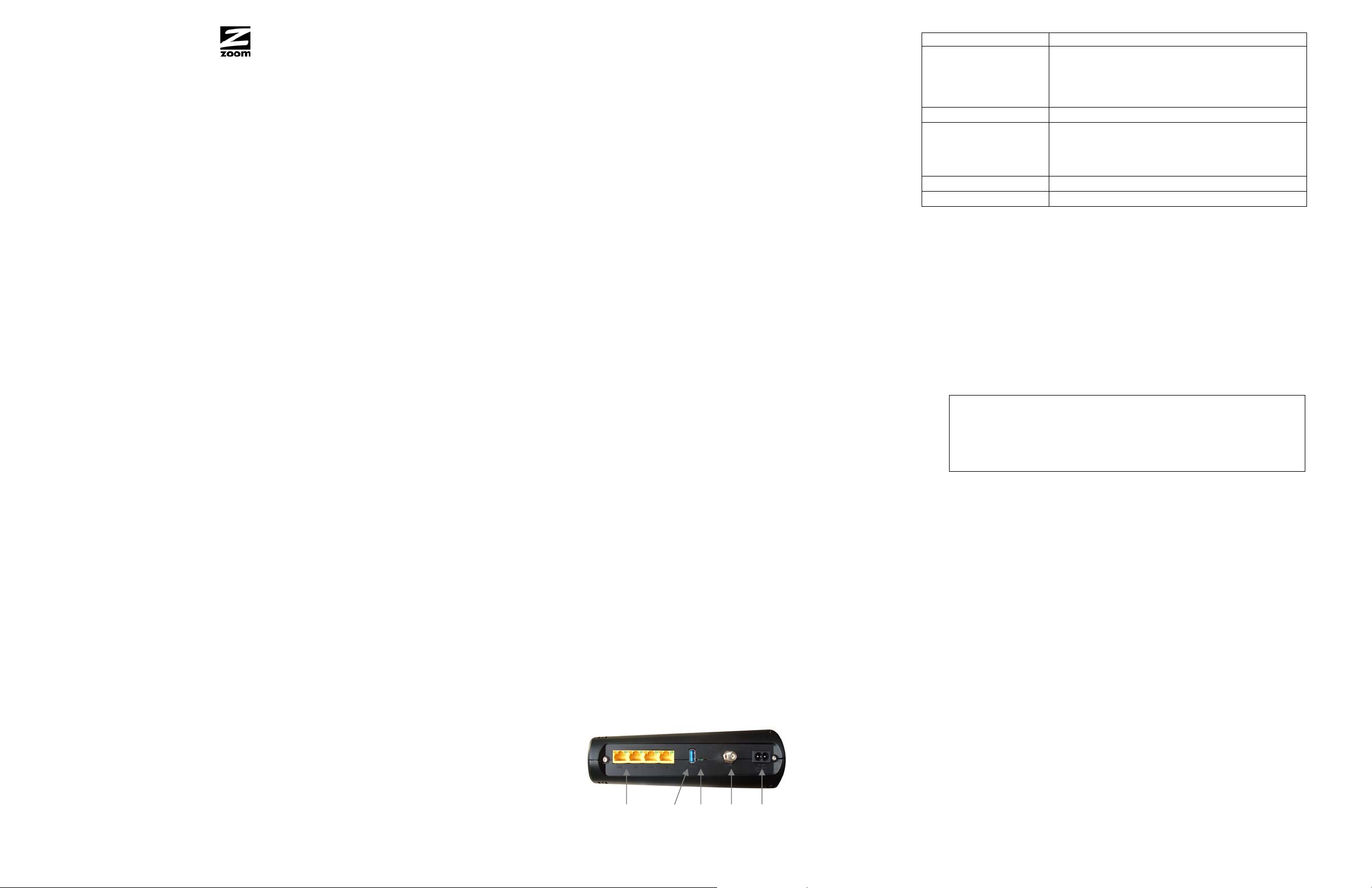
Hardware Connection
GE/ LAN 1-4 USB RESET Cable AC IN
Port Description
GE 1-4
(Gigabit Ethernet 1-4
also known as LAN
1-4)
USB
Four 10/100/1000 auto-sensing RJ-45 ports.
Connect devices on your LAN (Local Area
Network) such as a computer, hub or switch to
these ports.
The USB port is for manufacturer’s use only.
Use this button in the unlikely event that you
RESET
want to restore the default factory settings. This
button is recessed to prevent accidental resets of
your cable modem/router.
Cable
AC IN
Connect your coaxial cable line to this port.
Connect the supplied power cord to this port.
Connecting the Cable Modem/Router Wirelessly to Some Device
Your cable modem/router has wireless-N for WiFi® compatible connection to your
computer and/or other devices. The cable modem/router comes set up by default
with WPA/WPA2 security, and this can be changed if you like.
For those computer(s) and/or device(s) that support WPS, see Using WPS to set
up your wireless network. (Windows 7 SP1 (Service Pack 1) or the latest updates,
or Windows Vista SP2 (Service Pack 2) support WPS.) For those computer(s)
and/or device(s) that do support WPA/WPA2 but that don’t support WPS, enter the
default SSID and Pre-Shared Key below in the wireless network portion of the
device’s configuration menus.
Note: Typically, tablets like the iPad and e-readers don’t support WPS but do
support WPA/WPA2.
Default Wireless Security Settings
The default SSID is: ZOOM
The default Pre-Shared Key is: zoom#### where #### represents
the last 4 characters of the Cable MAC address of the unit, which
can be found on the label on the bottom of the cable modem/router.
Note: If you want to change the default SSID and Pre-Shared Key, please refer
to the User Manual on the CD for instructions.
In the unlikely event that one or more of your devices only supports WEP security, please
refer to the User Manual on the CD for instructions on how to configure WEP security.
Using WPS to set up your wireless network
If all the WiFi compatible wireless devices on your network support WPS:
1 Press the WPS LED pushbutton on the front panel of the router for 5 seconds.
The WPS LED should blink green.
2 Within 2 minutes (before the WPS LED light turns off), press the WPS button on
the device that you’re linking wirelessly to the modem/router. The button may be
a physical pushbutton on the device or a button on a page of the device’s
wireless network configuration menus.
3 Congratulations! You should now have a secure connection between the
router and a device. Now is a good time to check that your device’s Internet
connection is working. Open your browser and go to a familiar Web site. If you
are able to connect, continue with the next step below.
If you are not able to connect to the Internet, go to
4 If you have other devices whose WPS security you need to set, repeat steps 1
through 3 for each device. When they are all set, go to step 5.
5 Your basic setup for local wireless devices is complete.
Note: If you want to change the default SSID and Pre-Shared Key, please refer to
the User Manual on the CD for instructions.
Read This Only if You Are Connecting Additional Computers and/or
Other Devices to the Cable Modem/Router’s Ethernet/LAN ports
You can plug up to four computers, game consoles, or other Ethernet-capable devices into
the cable mo dem’s LAN ports. For information about your specifi c de vice, please refer
Troubleshooting Tips
.
Page 2

to the documentation that came with that device. Follow the instructions on the
other side of this Quick Start for each computer or other device.
1 If you connected the cable modem to a computer using a wired connection
when setting up the cable modem, unplug the computer now if you don’t want it
to stay connected to the cable modem.
2 To connect a computer or other Ethernet-capable device, plug one end of an
Ethernet cable into an available Ethernet (GE 1, 2, 3, or 4) port on the cable
modem and plug the other end of the Ethernet cable into the Ethernet port of
the additional device you want to connect to the cable modem. (If you are
connecting a hub or a switch, this is typically called an Uplink or Ex pansion
port.) If you are connecting a computer or game station, go to step 5 of
this section.
3 If you are connecting a network device such as a switching hub, use the
instructions that came with that device. Then reboot any computer that is part of
your network. For example, if you connected a switching hub, reboot any
computer that will make a wireless connection to that switching hub.
4 If you are connecting a HomePlug adapter pair with one adapter plugged into
the cable modem and an AC outlet, and the other adapter plugged into a
computer or game station and an AC outlet, make those connections and then
go to step 5.
5 Verify that your Internet connection is working. Open a Web browser on each
computer that’s using your network and try to connect to a familiar Web
address.
Note: If at any time you need to make changes to the cable modem’s
configuration, open a web browser from any PC on your cable modem’s
network and type http://192.168.0.1 to open the Zoom Configuration Manager.
Alternately, you can connect a computer directly to the cable modem, open its
browser, and then type http://192.168.0.1.
6 Congratulations! You have connected an additional device to the Internet. You
can connect up to 4 Ethernet-capable devices to the cable modem/router,
following the instructions above for each device and starting at step 2 of this
section.
Gaming
If you are using your cable modem for gaming, you may need to make changes to
the cable modem’s firewall setting for the game to work. This can be done by setting
up a DMZ or using port triggering. Please see the User Manual on the CD to decide
which option to select and instructions on setting it up.
Advanced Features
You can configure advanced features after logging in to the Zoom Configuration
Manager. Go to the section Logging in to the Zoom Configuration Manager.
Then refer to the User Manual on the CD for information about all the options on the
cable modem/router menu.
Logging in to the Zoom Configuration Manager
Step 1: Connecting the Router to a Computer
1 Connect the router to a computer following the instructions under How to
connect to a computer if you don’t have or choose not to use a cable
modem starter kit. Then continue to Step 2 below.
Step 2: Establishing Communication
1 Open your Web browser, enter http://192.168.0.1 in the address bar, and press
the Enter key to open the Cable Modem/Router configuration software.
2 In the Enter Network Password dialog box, type the following User Name and
Password in lower case, then click OK.
User Name: admin
Password: admin
3 The Status page should appear. If the Status page doesn’t appear, please see
Troubleshooting Tips.
From the Zoom Configuration Manager, you can configure advanced features and
make changes to the default wireless security options including the SSID and PreShared Key. Please refer to the User Manual on the CD for instructions.
Front Panel LEDs
Your Zoom cable modem has several lights on its front panel to help you monitor the
cable modem/router’s status.
Light Color Description
Power Green
DS
Green
Downstream
sync
US
Upstream sync
Blue
Green
Blue
DS & US Green
Online Green
USB Green
Green
Wireless
Blue
WPS Green
ON = power is supplied to the cable modem/router
OFF = power is not supplied to the cable modem/router
Blinking = scanning for DS channel
ON = synchronized on 1 channel only
ON = synchronized with more than 1 channel (DS Bond
mode)
Blinking = ranging is in progress
ON = ranging is complete on 1 channel only
ON = ranging is complete; operate with more than 1 channel
(US Bond mode)
Both DS and US blinking together = operator is performing
maintenance
Blinking = cable interface is acquiring IP, ToD, CM
configuration
ON = cable modem/router is operational
OFF = cable modem/router is offline
Blinking = data is flowing
ON = USB device is connected
OFF = no USB device connected
Blinking = data is flowing
ON = configured to 802.11g only or 802.11b/g auto mode
OFF = WiFi is disabled
Blinking = data is flowing
ON = configured to 802.11n only or 802.11b/g/n auto mode
OFF = WiFi is disabled
Blinking = WPS is in discovery mode (LED blinks for up to 2
minutes)
ON: LED lit solid for 30 seconds after WPS configuration is
successful
OFF (after 2 minutes blinking): no WiFi client associated with
the cable modem/router via WPS
Rear Panel LEDs
Green
GE / LAN 1-4
Amber
Blinking = data is flowing
ON = connected at 1 GMbps
OFF = no Ethernet link detected
Blinking = data is flowing
ON = connected at 10 or 100 Mbps
OFF = no Ethernet link detected
Troubleshooting Tips
Problem: I cannot access my Internet service or send or receive email.
Solution:
The following front panel lights on the cable modem/router – ONLINE,
US (upstream), DS (downstream), and POWER – must be solidly lit
before your modem will let you connect to the Internet. If they are not:
¾ Check all modem connections (power, Ethernet, and cable modem
line).
¾ Unplug your cable modem/router and then plug it back in.
¾ Restart your computer.
¾ Check to see that your cable TV is working.
¾ Check with your cable service provider to make sure that high speed
access is available and running.
¾ In rare instances, the cable signal may be weak or noisy. If this is
the case, call your cable service provider.
¾ If you are using your PC’s Ethernet port, check that this port is
functioning correctly. If you are using wireless, check that your
wireless connection is functioning correctly. Refer to its
documentation if necessary.
¾ Check that your Web browser is configured correctly. It should be set
to use a network connection (this might be called a Local Area
Network or broadband connection).
¾ Check that your computer’s network settings are configured
correctly. A Windows computer should have a local area connection
that should normally be Internet Protocol version 4, Internet Protocol
version 6, or TCP/IP; not AOL, Dial-up, or Adapter. A Macintosh
computer should be configured for Built-in Ethernet, and TCP/IP
should be set to Using DHCP.
If You Need Help
We encourage you to register your product and to notice the many support options available
from Zoom. Please go to www.zoomtel.com/techsupport. From here you can register your
router and/or contact our technical support experts and/or use our intelligent database
SmartFacts
Safety Issues & Warnings
WARNING: Risk of electric shock. Do NOT expose to water or moisture.
• The cable modem is a high-performance communications device designed for home and office
• Do NOT use the cable modem outdoors. Keep the cable modem in an environment that is between 0°C and
• To avoid overheating the cable modem, do NOT place any object on top of the cable modem.
• Do NOT place the cable modem in a confined space.
• Do NOT restrict the flow of air around the cable modem.
• The manufacturer assumes no liabilities for damage caused by any improper use of the cable modem.
• Make sure the voltages and frequency of the power outlet matches the electrical rating labels on the power
Regulatory Information
FCC Interference Statement
This equipment has been tested and found to comply with the limits for a Class B digital device pursuant to Part 15 of the FCC
Rules. These limits are designed to provide reasonable protection against radio in terference in a commercial environment. This
equipment can generate, use and radiate radio frequency energy and, if not installed and used in accordance with the
instructions in this manual, may cause harmful interference to radio commu nications. Ope ration of this equipment in a reside ntial
area is likely to cause interference, in which case the user, at his own expense, will be required to take whatever measures are
necessary to correct the interference. If this equipment does cause harmful in terference to radio or television reception, which
can be determined by turning the equipment off and on, the user is encouraged to try to correct the interference by one of the
following measures:
• Reorient or relocate the receiving antenna.
• Increase the separation between the equipment and receiver.
• Connect the equipment into an outlet on a circuit different from that to which the receiver is connected.
• Consult the dealer or an experienced radio/TV technician for help.
The device complies with Part 15 of the FCC Rules. Operation is subject to the following t wo conditions: (1) This device ma y not
cause harmful interference, and (2) this device must a ccept any interference received, including interference that may cause
undesired operation.
FCC Caution: Any changes or modifications not expressly approved by the party responsible for compliance could void the
user’s authority to operate this equipment.
For product available in the USA/Canada market, only channel 1~11 can be operated. Selection of other channels is not possible.
This device is going to be operated in 5.15~5.25GHz frequency range, it is restricted in indoor environment only.
IMPORTANT NOTE:
FCC Radiation Exposure Statement
This equipment complies with FCC radiation exposure lim its set forth for an uncont rolled environmen t. This equipm ent should be
installed and operated with minimum distance 20cm between the radiator & your body.
This transmitter must not be co-located or operating in conjunction with any other antenna or transmitter.
The availability of some specific channels and/or operational frequency bands are country dependent and are firmware
programmed at the factory to match the intended destination. The firmware setting is not accessible by the end user.
Note to CATV System Installer - This reminder is provided to call the CATV systems installe r's attention to Section 820- 93 of the
National Electric Code which provide guideline for proper grounding and, in particular, specify that the Coaxial cable shield s hall
be connected to the grounding system of the building, as close to the point of cable entry as practical.
1751-C 27667-EL ©2011
tm
and/or get warranty information.
US: (617) 753-0963
UK: London: +44 2033180660
UK: Manchester: +44 1618840074
environments.
40°C (between 32°F and 104°F).
cube.
 Loading...