

Page 1

C50
ICEBOX
User’s Manual
UM009701-0201
ZiLOG Worldwide Headquarters • 910 E. Hamilton Avenue • Campbell, CA 95008
Telephone: 408.558.8500 • Fax: 408.558.8300 • www.ZiLOG.com
Page 2

C50
ICEBOX
This publication is subject to replacement by a later edition. To determine whether a later
edition exists, or to request copies of publications, contact:
ZiLOG Worldwide Headquarters
910 E. Hamilton Avenue
Campbell, CA 95008
Telephone: 408.558.8500
Fax: 408.558.8300
www.ZiLOG.com
Document Disclaimer
ZiLOG is a registered trademark of ZiLOG Inc. in the United States and in other countries. All other products
and/or service names mentioned herein may be trademarks of the companies with which they are associated.
©2001 by ZiLOG, Inc. All rights reserved. Information in this publication concerning the devices,
applications, or technology described is intended to suggest possible uses and may be superseded. ZiLOG,
INC. DOES NOT ASSUME LIABILITY FOR OR PROVIDE A REPRESENTATION OF ACCURACY OF
THE INFORMATION, DEVICES, OR TECHNOLOGY DESCRIBED IN THIS DOCUMENT. ZiLOG
ALSO DOES NOT ASSUME LIABILITY FOR INTELLECTUAL PROPERTY INFRINGEMENT
RELATED IN ANY MANNER TO USE OF INFORMATION, DEVICES, OR TECHNOLOGY
DESCRIBED HEREIN OR OTHERWISE. Except with the express written approval of ZiLOG, use of
information, devices, or technology as critical components of life support systems is not authorized. No
licenses are conveyed, implicitly or otherwise, by this document under any intellectual property rights.
UM009701-0201
Page 3

C50 ICEBOX
:
UM009701-0201
USER'S MANUAL
Electrical
Safeguards
WARNING
Follow the precautions listed below to avoid permanent damage to the emulator.
If the target application board has its own power supply, follow the power-up and powerdown procedures in the precise order shown below 1:
I. Always use a grounding strap to prevent damage resulting from electrostatic
discharge (ESD)
II. Power-Up Precautions
1. Remove V
2. Power-up the emulator
3. Depress the emulator RESET button
4. Connect the target pod to the target application
5. Power-up the target application (if any)
jumper J1
CC
2
3
III. Power-Down Precautions
When powering down, follow this procedure in the precise order shown below:
1. Depress the RESET button on the emulator
2. Power-down the target application board (if any)
3. Remove the target pod
4. Power-down the emulator
Notes:
1. Refer to the "Precaution List" section in Chapter 5 for additional operating precautions
specific to various devices.
2. Do not leave the emulator powered up with the RS-232 cable connected to a powereddown PC.
3. Before inserting target pod into target application board, refer to Chapter 2 to determine
appropriate jumper selections and options.
Page 4

Zilog C50 ICEBOX
UM009701-0201
™
User's Manual
About This Manual
We recommend that you read and understand everything in this manual before setting up and
using the product. However, we recognize that users have different styles of learning: some will
want to set up and use their new emulator while they read about it; others will open these pages
only as a “last resort” to check on a particular specification. Therefore, we have designed this
manual to be used either as a “how to” procedural manual or a reference guide to important data.
Additional assistance is provided in the following ways:
■ The emulator graphical user interface (GUI) features a complete, context-sensitive on-line
help facility that provides brief messages on keyboard and ICEBOX commands and various
procedures on how to use the emulator. An index and glossary are also included as part of
this Help Program.
■ The complete emulation board schematic diagram is included at the back of this user's
manual.
Please fill out and return the enclosed Zilog Registration Cards as soon as possible so we can
advise you of updates and improvements to your emulator.
Page 5

C50 ICEBOX™ USER'S MANUAL
UM009701-0201
TABLE OF CONTENTS
TITLE PAGE
HAPTER 1: INTRODUCTION
C
OVERVIEW ....................................................................................................................... 1-1
EY FEATURES ................................................................................................................ 1-1
K
UPPORTED ZILOG Z8
S
GUI-S
H
S
R
HAPTER 2: SETUP AND INSTALLATION
C
UPPORTED COMPILER, ASSEMBLER FORMATS ............................................................. 1-2
ARDWARE SPECIFICATIONS .............................................................................................. 1-2
UPPORT PRODUCTS PACKAGE CONTENTS .......................................................................... 1-2
EQUIREMENTS AND RESTRICTIONS .................................................................................... 1-4
INSTALLING THE SOFTWARE ............................................................................................... 2-1
NSTALLING THE HARDWARE (QUICK INSTALLATION) .............................................................. 2-2
I
NSTALLING THE HARDWARE (COMPLETE INSTALLATION) ........................................................ 2-3
I
ONFIGURING FOR INTERNAL ROM .................................................................................... 2-3
C
ONNECTING TO A POWER SUPPLY .................................................................................... 2-3
C
ONNECTING THE SERIAL CABLE TO THE PC ....................................................................... 2-3
C
ONNECTING TO YOUR DESIGN ......................................................................................... 2-4
C
ETTING UP THE OSCILLATOR AND OPTION JUMPERS............................................................ 2-5
S
ONNECTING TO A LOGIC ANALYZER .................................................................................. 2-8
C
OWERING UP/POWERING DOWN ....................................................................................... 2-9
P
MULATOR OPERATION ..................................................................................................... 2-9
E
®
DEVICES ....................................................................................... 1-1
C
HAPTER 3: Z8
®
EMULATOR SAMPLE SESSION
STARTING THE APPLICATION .............................................................................................. 3-1
ONITORING/MODIFYING/DOWNLOADING FILES .................................................................... 3-3
M
SING THE DEBUG WINDOW.............................................................................................. 3-4
U
OTP O
W
S
R
M
PERATIONS ........................................................................................................... 3-4
INDOW REFRESH ........................................................................................................... 3-4
AVING AND QUITTING ...................................................................................................... 3-4
UNNING MULTIPLE INSTANCES ......................................................................................... 3-5
ULTITASKING WITH OTHER WINDOWS APPLICATIONS .......................................................... 3-6
Page 6

TABLE OF CONTENTS
Note: Appendix C is not available.
UM009701-0201
(Continued)
TITLE PAGE
C
HAPTER 4: SUMMARY OF MENUS, COMMANDS, AND OPERATIONS
MAIN MENU .................................................................................................................... 4-1
ONFIGURATION DIALOG BOX ........................................................................................... 4-1
C
ILE MENU...................................................................................................................... 4-1
F
ICEBOX M
EBUG MENU ................................................................................................................. 4-6
D
OTP M
UN MENU ..................................................................................................................... 4-8
R
EBUG WINDOW ELEMENTS .............................................................................................. 4-8
D
INDOW REFRESHING .................................................................................................... 4-10
W
AVING SESSIONS/RELOADING "SAVED" SESSIONS .............................................................. 4-10
S
ARDWARE RESET ......................................................................................................... 4-11
H
ELP ............................................................................................................................ 4-11
H
C
HAPTER 5: TROUBLESHOOTING G UIDE AND PRECAUTION LIST
TROUBLESHOOTING GUIDE ................................................................................................ 5-1
RECAUTION LIST............................................................................................................. 5-2
P
ENU .............................................................................................................. 4-2
ENU..................................................................................................................... 4-7
A
PPENDIX A: HOW TO RECEIVE ZILOG SAMPLE FILES .......................................................... A-1
PPENDIX B: SYMBOL FILE FORMATS ................................................................................ B-1
A
PPENDIX C: EMULATOR SCHEMATICS ............................................................................... C-1
A
Page 7

C50 ICEBOX
UM009701-0201
USER'S MANUAL
U
SER'S MANUAL
CHAPTER 1
I
NTRODUCTION
OVERVIEW
Congratulations on selecting a fine development tool! The Zilog C50 In-Circuit Emulator
™
(ICEBOX
and useful features to shorten your development time for Z8
to "Supported Zilog Z8
runs under MS-Windows for Zilog’s Z8 family of emulators.
KEY FEATURES OF THE ZILOG EMULATO R
) is carefully engineered to provide the best balance between reasonable cost
®
CCP™-based products (refer
®
Devices" section). The emulator graphical user interface (GUI)
■ Edit the contents of Program Memory or the registers, track memory locations, set break
points in ROM, and single-step into codes.
■ Multiple windows can be viewed and the contents of Program Memory, External
Memory, and register files can be edited.
■ Multiple emulators can be operated simultaneously, provided enough serial
communication ports on your PC are available.
■ Because of the multitasking feature of the emulator GUI, you can use other Windows
applications while the emulator GUI is running.
■ Learn about the emulator and start writing and debugging software using the memory
available in the emulator—with or without a finished design.
SUPPORTED ZILOG Z8® DEVICES
Emulation OTP Programming
Support Support
Z86C03 Z86E03
Z86C06 Z86E04
Z86C09 Z86E06
Z86C16 Z86E07
Z86C19 Z86E08
Z86C30 Z86E30
Z86C31 Z86E31
Z86C40 Z86E40
Z86C90
1-1
Page 8

C50 ICEBOX
UM009701-0201
USER'S MANUAL
GUI-SUPPORTED COMPILER, ASSEMBLER FORMATS
The emulator GUI supports object (binary or Intel hex) produced by the Zilog Z8® and the
Production Language Corporation (PLC) assembler.
HARDWARE SPECIFICATIONS
Dimensions 2.5in H x 6.25in W x 9.5in D
Target Clock or Oscillator Frequency 1 to 20 MHz (shipped with 12 MHz crystal)
Internal Clock Operating Frequency 500 kHz min for all modes of operation
Host Interface DB-25, RS-232 DCE (TxD, RxD only)
Serial Baud Rate 19,200 bps
Power Supply Voltage +4.75 VDC to +5.25 VDC Max (+5.0 VDC typical)
Power Supply Current 0.6 A typ
Operating Temperature 20 degrees C, ±10 degrees C
Operating Humidity 10-90% RH (non-condensing)
SUPPORT PRODUCTS PACKAGE CONTENTS
The Zilog Emulator Support Products Package contains the following items:
Hardware
C50 ICEBOX Emulator
18-pin Target Pod
28-pin Target Pod
40-pin Target Pod
25-pin RS-232 Cable
15-inch Power Cable
Z86E30 28-pin DIP OTP Device
Z86E40 40-pin DIP OTP Device
Software
®
GUI Diskette
Z8
ZASM-Cross Assembler Diskette
MOBJ-Object Utility Diskette
1-2
Page 9

Description of Z8® GUI Diskette Files
UM009701-0201
z8cfg.o Configuration
z8ice.exe Executable
icehelp.hlp Help
meter.dll Installation library
readme Text file
setup.inf Installation information
setup.exe Windows install program
z8em_c12.o On board software for Z86C12 Emulator
z8em_c27.o On board software for Z86C27 Emulator
z8em_c50.o On board software for Z86C50 Emulator
z8em_c62.o On board software for Z86C62 Emulator
z8em_c65.o On board software for Z89C65 Emulator
z8em_c67.o On board software for Z89C67 Emulator
z8em_c93.o On board software for Z86C93 Emulator
z8em_l7x.o On board software for Z86L7X Emulator
z8em_ccp.o On board software for Z86CCP Emulator
C50 ICEBOX
USER'S MANUAL
Publications
™
Zilog C50 ICEBOX
User's Manual
asm S8, Super8/Z8 Cross Assembler User's Guide
Zilog Universal Object File Utilities User's Guide
Registration Cards
1-3
Page 10

C50 ICEBOX
UM009701-0201
USER'S MANUAL
REQUIREMENTS
Minimum Hardware
An IBM PC (or 100 percent compatible) 386-based machine at 20 MHz with 4 MB RAM,
hard disk drive (with 1 MB available), 5.25- or 3.5-inch floppy disk drive, and VGA video
adapter.
Note: A 486-based machine will provide increased overall performance.
Minimum Software Operating Systems
MS-DOS version 5.0
MS-Windows version 3.0
Additional Required Items Not Supplied with the Support Package
A source of power (+4.75 VDC to +5.25 VDC Max [+5.0 VDC typical]) for the emulator. This
can be a laboratory power supply with supply current of 0.6 ampere.
®
Your Z8
Typically, this is a wire-wrapped or printed-circuit prototype that includes a socket for the
Z8 CCP device, into which you can plug the emulation cable from the emulator.
CCP™-Based Design
RESTRICTIONS
This emulator is designed for emulation purposes only and cannot be used in standalone
operation.
RC oscillator emulation is not supported.
1-4
Page 11

C50 ICEBOX
UM009701-0201
USER'S MANUAL
U
SER'S MANUAL
CHAPTER 2
S
ETUP AND INSTALLATION
INSTALLING THE SOFTWARE
To properly install the Z8® Emulator GUI, first start the Windows application, then follow
these steps:
1. Load the Z8 Emulator GUI diskette into compatible disk drive.
2. Select the Run command from the File menu, located under Windows Program
Manager.
3. Type in the following at the prompt:
“a:\setup” (or “b:\setup” if the diskette is in drive B:)
A dialog box will now prompt you for the directory into which the software will be installed
(default is C:\Z8-ICE).
The setup program will copy the files into the target directory, creating a Z8-ICE icon in the
Windows environment.
After the installation is finished, you can move the Z8-ICE icon into any program group of
your choice.
Notes:
1. The installation procedure does not modify the “win.ini”, “autoexec.bat” or “config.sys”
files.
2. An alternative way to install the Z8 Emulator GUI software is to copy all the files
described in the following section to your target directory and manually create a
program item by using the “New” command under the File menu of the Windows
Program Manager. (Consult MS-Windows documentation if you need additional
information about alternate install procedures.)
2-1
Page 12
C50 ICEBOX
UM009701-0201
USER'S MANUAL
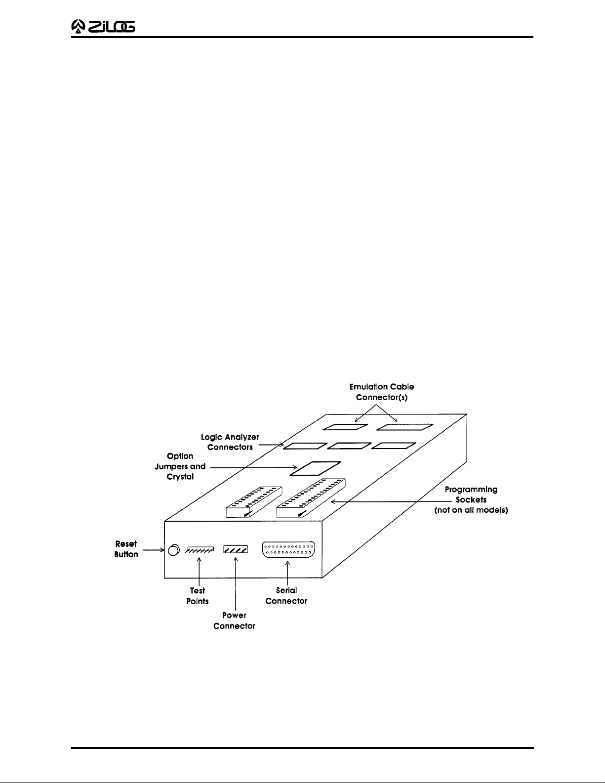
INSTALLING THE HARDWARE
Before installing the hardware, refer to Figure 2-1 for a rear view of the “generic” emulator
and Figure 2-2, which provides a diagram for connecting the emulator to your PC and
power supply.
Note: Proper functioning of the emulator assumes that the GUI software has been properly
installed and runs correctly on your PC.
Quick Installation
This section provides you with a quick overview of the steps involved in setting up the
hardware. The "Complete Hardware Installation" section, which immediately follows,
provides a more detailed description of the hardware setup procedure.
1. Configure the emulator for internal ROM (if running in ROM Mode).
2. Connect to a +5V power supply and adjust to 0.6A (min.).
3. Connect the serial cable to the PC.
4. Connect the emulator to your design.
5. Set up the oscillator and option jumpers. (Refer to Table 2-1 and Figures 2-3 and 2-4.)
6. Connect the emulator to a logic analyzer (if using).
7. Power up the emulator. (Refer to "Powering Up" and "Powering Down" procedures.)
2-2
Figure 2-1. “Generic” Emulator (Rear View)
Page 13

C50 ICEBOX
UM009701-0201
USER'S MANUAL
Complete Hardware Installation
Configuring for Internal ROM. (You may skip this paragraph if you are using external
ROM.) This emulator is configured to run in "ROMless Mode," that is, it uses external ROM
(Port 1 of the Z8 for multiplexed addresses and data). If, however, your application requires
ROM Mode, follow these steps to reconfigure the emulator.
1. Remove the screws from bottom of the emulator and pull off the bottom of the case.
2. Straighten the handles of the programming sockets to an upright position.
Note: We recommend that you leave the black front and back panels with the board.
3. Locate the socketed 20-pin IC labeled "U3" on the daughterboard.
Note: For future reference, note the location of Pin 1.
4. Carefully remove the IC from the socket.
Note: Use an IC puller or small, flat-bladed screwdriver, being careful not to bend the
pins. Store in a safe place; the IC can be replaced on the daughterboard when using
applications that involve ROMless Mode.
5. Locate the jumper header, which has eight jumper wires running diagonally across the
top. Plug the header into the U3 socket so that Pin 1 is in the same corner formerly
occupied by the IC Pin 1.
6. Carefully reassemble the emulator and replace the screws that hold the case together.
Connecting to a Power Supply. If your power supply allows voltage adjustment, do the
following:
1. Turn the power supply on and adjust it to +5V.
2. Set it for at least 0.6A, if there’s a current-limiting adjustment.
3. Turn the supply off or make sure a nonadjustable supply is off.
4. Locate the power cable (red wire, black wire, and banana plugs on one end). Plug in
the black banana plug into the black jack on the power supply (labeled COM, GND, or
with a ground symbol). Plug in the red plug into the red jack on the power supply
(labeled "+" or "+V" or "+5V").
5. Plug the white connector on the other end of the cable into the matching 4-pin connector
on the back of the emulator. (This connection is "keyed" to ensure against an improper
connection.)
Connecting the Serial Cable to the PC. Locate the serial cable and connect the male end
to the female connector on the back of the emulator, then connect the female end to either
the COM1, COM2, COM3, or COM4 connector of your PC.
Note: If connector availability is limited to a 9-pin COM1 through COM4, use a different
cable or a 25- to 9-pin converter. (Zilog does not provide either of these items.)
2-3
Page 14

C50 ICEBOX
UM009701-0201
USER'S MANUAL
INSTALLING THE HARDWARE (Continued)
Connecting to Your Design. (If your design is ready.) Locate the emulation cable for your
®
CCP™-based design.
Z8
Note: Wear a properly grounded wrist strap or similar ESD protection before proceeding
with this step.
Plug one end of the emulator cable into your Z8 CCP socket, being very careful to orient
the Pin 1 marking (as indicated by the red mark on the ribbon cable) to match the way your
board is built. Plug the other end of the cable into the matching blue connector on top of
the emulator.
Note: The inductance and capacitance of the emulation cable may affect the signals to
and from the emulator and target board, especially if the target board has low-current
drivers, pull-ups, and pull-downs. We recommend that you drive the XTAL pins of the Z8
with the crystal oscillator on the emulator with the J2/J3 Jumpers removed.
®
2-4
Figure 2-2. Emulator Hook-Up Diagram
Page 15

C50 ICEBOX
UM009701-0201
USER'S MANUAL
Setting Up the Oscillator and Option Jumpers. The oscillator and option jumpers are
accessible on top of the emulator (see Figure 2-3). The clock for the emulated Z8 CCP
can be provided from an oscillator in the emulator or from a TTL-level clock on your design.
For electrical reasons, it cannot be provided from the oscillator on your design until you’re
done using the emulator and have done one of three things: 1) programmed an EPROM
or OTP Z8
and installed it in your design, 2) programmed an external EPROM and installed
it and a ROMless Z8 in your design, or 3) installed a masked-ROM Z8 in your design.
Note: Each emulator is shipped with a standard oscillator, typically 12 MHz. If you want
another rate, remove the stock oscillator and install a different one.
The option jumpers, which are located on the top cover, allow you to configure things like
whether the emulator provides power to your design on the V
pin(s) of the emulated Z8
cc
CCP, and how the clock pin of the emulated Z8 CCP is connected (refer to Table 2-1).
™
2-5
Page 16

INSTALLING THE HARDWARE (Continued)
UM009701-0201
C50 ICEBOX
USER'S MANUAL
2-6
Figure 2-3. Emulator (Top View) for Jumper Locations
Page 17

Table 2-1. Emulator Jumper Options
UM009701-0201
Jumper Installed Open
J1 Emulator supplies power to target board Emulator power isolated from target board.
pin(s) of Z8® CCP™.
via V
CC
J2 XTAL2 pin of the emulator ICE chip is XTAL2 not interconnected.
connected to XTAL2 pin of Z8 CCP Pod.
(Target board can use clock from emulator
— remove crystal.) Refer to Figure 2-4.
J3 XTAL1 pin of Z8 CCP emulator connected XTAL1 not interconnected.
to XTAL1 pin of Z8 CCP Pod. (Target clock
runs emulator— remove crystal.)
J4–J7 Reserved. Reserved.
C50 ICEBOX
USER'S MANUAL
Crystal, Resonator, or Inductor
Figure 2-4. Jumper Options Diagram
Emulator
ICE Chip
XTAL2 XTAL1
J2
XTAL2 XTAL1
Target
Pod
J3
2-7
Page 18

C50 ICEBOX
UM009701-0201
USER'S MANUAL
INSTALLING THE HARDWARE (Continued)
Connecting to a Logic Analyzer. Connect termination adapters between each gray
connector on top of the emulator and the pod connector of the logic analyzer.
Table 2-2. Emulator Logic Analyzer Connections
HP P9 (Con. 1) P10 (Con. 2) P11 (Con. 3) P12 (Con. 4) P13 (Con. 5) P14 (Con. 6)
Pin Analyzer Sig. Name Sig. Name Sig. Name Sig. Name Sig. Name Sig. Name
1 (NC) (NC) (NC) (NC) (NC) (NC) (NC)
2 (NC) (NC) (NC) (NC) (NC) (NC) (NC)
3 CLK /AS /DS SCLK /REGWR /REGRD /MAS
4 D15 A15 ICRAM P37 /BRP_ROM TCLK P17
5 D14 A14 /DS P36 P20_DI /CE_ERF P16
6 D13 A13 /AS P35 CT0 /REGWR P15
7 D12 A12 R/W P34 P27_D0 /REGRD P14
8 D11 A11 SCLK P33 /STOP RBP3 P13
9 D10 A10 /SYNC P32 P34_SK RBP2 P12
10 D9 A9 IACK P31 /STOPREC RBP1 P11
11 D8 A8 /RESET P30 P35_SS RBP0 P10
12 D7 A7 D7 P27 IWD7 RA7 P07
13 D6 A6 D6 P26 IWD6 RA6 P06
14 D5 A5 D5 P25 IWD5 RA5 P05
15 D4 A4 D4 P24 IWD4 RA4 P04
16 D3 A3 D3 P23 IWD3 RA3 P03
17 D2 A2 D2 P22 IWD2 RA2 P02
18 D1 A1 D1 P21 IWD1 RA1 P01
19 D0 A0 D0 P20 IWD0 RA0 P00
20 Gnd Gnd Gnd Gnd Gnd Gnd Gnd
2-8
Page 19

C50 ICEBOX
:
:
UM009701-0201
USER'S MANUAL
WARNING
If your design already has a power supply, do not power from the emulator VCC pin.
Powering Up. If anything unusual (such as unexpected sounds and smells) occurs the
first time you turn on the power supply, quickly turn off the power supply and check your
connections. If your power supply allows voltage adjustment, adjust it again to +5V. (The
value may be somewhat lower than +5V because of the load of the emulator.) If it has a
current meter, ensure that the emulator is drawing within the rated current.
®
After power-up, depress the RESET button to reset the Z8
powering your design through the V
pin, turn on the power supply of the design.
CC
ICE Chip. If the emulator is not
Powering Down. When powering down, follow the procedure described below:
1. Depress the RESET button on the emulator.
2. Power-down the target application board (if using its own power supply).
3. Remove the target pod.
4. Power-down the emulator.
EMULATOR OPERATION
Resetting the Emulator. Pressing the RESET button on the emulator resets the state of
the target Z8 CCP and much of the status that you establish using the GUI. For example,
it resets the emulated ROM size to 4 Kbytes, and clears all 32 Kbytes Breakpoint ROM. If
your application board drives the /RESET pin of the Z8 CCP socket Low, the target Z8 CCP
is reset. For example, it sets the Program Counter to %000C, but does not affect most of
the other GUI and emulator status.
Note: After reset, you must wait a minimum of 5 seconds (for completion of self tests)
before starting GUI.
WARNING
To run the emulator, you must always press the RESET button on the emulator before
selecting the Z8-ICE icon.
ROM Size. The emulator has the selectable ROM size of 4K, 8K, 16K, and 32K.
Breakpoint Implementation. The emulator bases its breakpoint facility completely on
addresses, rather than on inserting special “Trap” instructions into the program, which
means you can set breakpoints in ROM on your target board. The emulator reads a
32Kx1 static RAM for each cycle emitted by the Z8 CCP during code execution.
EPROM/OTP Programming
The emulator provides OTP programming for the following devices: Z86E40, Z86E06*,
Z86E30, Z86E04, Z86E3, Z86E03*, Z86E08, and Z86E07†. (Refer to Table 2-3: Emulator
Programming Operations and Functions.)
* OTP device not currently available.
† Use the E08 option to program the E07.
2-9
Page 20

C50 ICEBOX
UM009701-0201
USER'S MANUAL
Emulator Programming Operations
Table 2-3. Emulator Programming Operations and Functions
Operations Functions Performed
BLANK CHECK Checks whether the OTP device is blank.
VERIFY Compares the contents of the emulator code memory and the
OTP device.
PROGRAM Writes the contents of the emulator code memory to the OTP
device.
EXAMINE Reads the contents of the OTP to the emulator code memory.
CHECKSUM Calculates the checksum of the OTP device only and displays
it on the screen. (Note: Checksum differences are explained in
the “OTP” section in Chapter 4: Summary of Windows,
Commands, and Operations.)
ROM protect ROM protection programming option.
RAM protect RAM protection programming option.
Low Noise Low-noise programming option for Z86E08 and Z86E04 only.
RC RC programming option.
Notes:
1. Do not keep the OTP device in the ZIF socket while in Emulation Mode.
2. When programming a device, ensure that other programming sockets are empty.
Emulator Test Points
There are seven numbered test points on the back of the emulator; however, not all of the
test points are used. The following table lists and describes the test points.
Table 2-4. Emulator Test Points
Number Description
1 Ground
2 Goes low during data strobe when the Z8 accesses a
breakpoint location.
4 Goes high whenever the emulator is emulating due to a GO;
goes low due to a STOP operation.
7 If this input is low (for example, if jumpered to Test Point 1),
2-10
the emulator doesn't stop emulating when it reaches a
breakpoint, but continues to produce a pulse on Test
Point 2.) This feature allows you to use the Breakpoint facil-
ity of the emulator to control or trigger external equipment.
Page 21

U
UM009701-0201
SER'S MANUAL
CHAPTER 3
C50 ICEBOX
USER'S MANUAL
Z8® E
MULATOR SAMPLE SESSION
Z8® EMULATOR SAMPLE SESSION
This sample session is designed to introduce you to the features of the Z8® graphical user
interface (GUI) software and thoroughly acquaint you with the various GUI windows you
will be using in this program. For best results, follow the steps in sequential order. Topic
headings (such as “Using the Debug Window”) have been added to the Sample Session
Procedure so you can better pinpoint specific topical “how to” information.
The chapter concludes with some brief notes and some figures that help explain the
multiple window and multitasking capabilities of the GUI software. (Refer to Chapter 4:
Summary of Menus, Commands, and Operations for more information about all elements
of the GUI.)
Note: In order to properly demonstrate the program features, be prepared to import
sample files (at procedural step 8) in this session. You can download Zilog sample files
from Zilog's Bulletin Board Service (ZBBS). (Refer to Appendix A for the procedure to
obtain these files.
Starting the Application
1. Press the RESET button on the emulator.
2. Double click the Z8-ICE icon.
Confirm the COM port connections; change the default if necessary. The change is
saved and will become the new default the next time around. If the communication
attempt between PC and the emulator fails, you may have to check the connection or
reset the emulator.
3. Wait for the initialization procedure to complete.
4. Click the OK button to continue (or the CANCEL button to quit), after the self-testing
results are displayed.
®
Microcontroller Emulation
Z8
5. Select the Z8 microcontroller currently being emulated from the microcontroller section
in the Configuration Dialog Box (see Figure 3-1).
3-1
Page 22

Z8 EMULATOR SAMPLE SESSION (Continued)
UM009701-0201
C50 ICEBOX
USER'S MANUAL
Figure 3-1. Zilog ICEBOX Configuration Dialog Box
6. Select the emulation ROM size (see Figure 3-1, which shows this value as “4K”). This
affects the size of the code file you can download.
Note: The Configuration dialog box is only accessible when no other window is open.
7. Click on the OK button (or depress the RETURN key) to accept the configuration.
8. Open the Code Memory window under the menu named ICEBOX.
If the characters are either too small or too large, use the Font Size menu to choose an
appropriate font size. You can scroll up and down the memory space, “size” the
window, make direct memory changes, and use the tracking facility to reach a
particular memory location.
3-2
Page 23

C50 ICEBOX
UM009701-0201
USER'S MANUAL
Figure 3-2. Various ICEBOX Windows
Monitoring/Modifying/Downloading Files
®
9. Use the File menu to download your sample file to the Z8
Code Memory (refer to
Appendix A: How to Receive Zilog Sample Files). The Code Memory window is updated
to show the current memory content.
Note: When downloading a hexadecimal file, the file size showing in the file downloading dialog box is the size of the memory the downloaded file will occupy, not the actual
file size.
10.Open a Register window and modify the values of the registers.
Note: Be careful in modifying ports or read-only registers, since the values represented on the screen cannot be changed for those registers. The write-only registers
will display values that may not represent the real values loaded for those registers.
11.Open an Extended Register window and modify the registers.
12.Open a Status window and a Counter/Timer window to monitor the special registers.
3-3
Page 24

C50 ICEBOX
UM009701-0201
USER'S MANUAL
Using the Debug Window
13. Open the Debug window.
The content of the Program (Code) Memory is disassembled and listed here. You can
do line-down or page-down to get around in the code list, but page-up or line-up is
not supported. You can do a direct jump to any particular memory address.
14. Set a break point and start the program by clicking the GO button.
Notes:
1. The mouse cursor is changed to a sand glass shape. The only action allowed
after a “GO” is halt. If there are no break points, click on the HALT button
to halt the execution.
2. If the application inadvertently goes into STOP Mode, the only way to halt the
emulator execution is by doing a Stop-Mode Recovery (as defined by the user
program). You may also reset the application using the RESET button.
15. Click on the HALT button to halt an execution.
OTP Operations
16. Select the OTP menu item under the Code Memory menu or Debug menu of the
emulator. An OTP dialog box is opened from which you can perform the operations
of OTP. Close the OTP window by selecting the Quit menu item.
Window Refresh
17. Double click on caption bar of the Register window to refresh it and check the value
of the registers.
Saving and Quitting
18. Select “Save Session” from the File menu to save the current setting in a session file.
The next time you use the interface, you can reload the last session by using the “Load
Session” command in the File menu.
19. Quit the application.
3-4
Page 25

C50 ICEBOX
UM009701-0201
USER'S MANUAL
RUNNING MULTIPLE INSTANCES
The Z8® emulator will allow several emulators running at the same time, if your PC has more
than one communication port. Figure 3-3 shows two emulators running at the same time.
Figure 3-3. Running Multiple Instances
Note: Running multiple instances of the Z8 emulator GUI (two or more emulators running
simultaneously) requires more memory than single-emulation operation; therefore, we
recommend using a PC with 8 Mbytes RAM. In addition, two more communication ports
are needed when running multiple instances.
3-5
Page 26

C50 ICEBOX
UM009701-0201
USER'S MANUAL
MULTITASKING WITH OTHER WINDOWS APPLICATIONS
You can simultaneously run your emulator and other windows applications. Figure 3-4
shows an emulator working under the MS-Windows multitasking environment.
Figure 3-4. Multitasking with Other Windows Applications
3-6
Page 27

C50 ICEBOX
UM009701-0201
USER'S MANUAL
U
SER'S MANUAL
CHAPTER 4
S
UMMAR Y OF MENUS
AND OPERATIONS
MAIN MENU
ICEBOX Configuration File Help
The Main Menu window of the emulator graphical user interface (GUI) is displayed after
the GUI program is started. The following menu items can be accessed from this Main
Menu:
■ ICEBOX Menu
■ Configuration Dialog Box
■ File Menu
■ Help
, C
OMMANDS
,
Each of these Main Menu items, along with all windows, subset menus, menu items,
commands, and operations, are summarized in the following sections of this chapter.
CONFIGURATION DIALO G BOX
At start-up, the emulator GUI automatically detects which emulator is in use. (The user,
however, can overwrite this by using a command-line option.) When a configuration dialog
box is shown on the screen, you can choose the microcontroller and the ROM size you want
to emulate. The code file you download to Code Memory is limited to the ROM size
selected. Selected ports automatically reference port availability in the selected microcontroller. Other information about the microcontroller, such as the number of ports and
extended register banks, can be observed but cannot be altered. Click the OK or CANCEL
button to confirm or cancel the configuration.
Note: To modify the configuration, you must first close all open windows; the configuration
command then reappears in the Main Menu.
FILE MENU
File-related commands are grouped under this menu. These commands are briefly
described below.
Download To Z8 Code Memory: download a piece of Intel hexadecimal (hex) or binary
format code to Code Memory (Note that when downloading a hex file, the file size showing in the file
downloading dialog box is the size of the memory the
downloaded file will occupy, not the actual file size.)
4-1
Page 28

C50 ICEBOX
UM009701-0201
USER'S MANUAL
FILE MENU (Continued)
Upload Code Memory: Save Z8® Code Memory (part or whole) to a file in binary
or Intel hex format.
Upload Data Memory Save Z8 Data Memory (part or whole) to a file in binary
or Intel hex format.
Open Session: Load a previously saved session.
Save Session: Save the information of the current session: window
positions, code file name, debug flags, font size, and so
on, into a file that has a default extension ".prj."
ICEBOX MENU
ICEBOX Configuration File Help
From this menu you can open a number of windows and exit the application. Some
windows can be opened multiple times, such as Registers, Ext. Registers, Code Memory,
Data Memory, Status, Ports, and Counter/Timers. The Debug window can only be opened
once. (A grayed menu item means that the corresponding window cannot be opened from
the selected menu.)
Registers
The following menu bar is displayed when the Registers menu item is selected:
ICEBOX File Tracking Font Size Window Help
Register Window
This window displaying the Z8 register file can be edited directly at the location of the
cursor. The ASCII representation of the contents is on the right. The current “working
register bank” is highlighted. The cursor can be moved around the window by using the
mouse or the arrow keys or by setting tracking options in the “Tracking” menu.
ICEBOX File Tracking Font Size Window Help
Selecting the "Tracking" menu produces the following menu items: Absolute Address
Dialog Box, the Indirect (@Rg) Dialog Box, and the Register Pointer Message Box, which
displays the register pointer value in hex format.
4-2
Page 29

C50 ICEBOX
UM009701-0201
USER'S MANUAL
Absolute Address
You can track to a register by its absolute address by entering the absolute address value
in the dialog box that appears when Absolute Address is selected from the ICEBOX
Tracking menu. The Absolute Address Dialog Box is shown in Figure 4-1
Indirect (@Rg)
You can indirectly track to a register (contents of which are the address of another register)
by entering the value in the Indirect (@Rg) Dialog Box, which appears when the Indirect
(@Rg) menu item is selected from the ICEBOX Tracking menu.
Register Pointer
The Register Pointer Message Box displays the address of the content of the Register
Pointer register. After clicking the OK button, the address value will be highlighted in the
Z8 Register window.
Font Size
You can choose from a number of font sizes: Point 6 to Point 12. However, since each
system and video type may have its own font set, some font sizes may not be suitable,
especially on a VGA display.
Window
The currently opened windows are listed under this menu. You can rearrange the positions
of the windows on the screen in different ways by using the commands from this menu.
Figure 4-1. ICEBOX Absolute Address Tracking Window.
4-3
Page 30

C50 ICEBOX
UM009701-0201
USER'S MANUAL
ICEBOX MENU (Continued)
Ext. Registers
The following menu bar is displayed when the Registers menu item is selected:
ICEBOX File Define Font Size Window Help
Ext. Registers Window
This window displays the available extended register banks of the emulated microcontroller. You can display more banks by selecting the Define menu item. The bank selected by
the register pointer is highlighted. Editing can be done directly on all banks without
changing the register pointer.
Data Memory
The following menu bar is displayed when the Data Memory menu item is selected:
ICEBOX File Tracking Edit OTP Font Size Window Help
Data Memory Window
This window displays the Z8 Data Memory (sometimes called External Memory). Notice
that Data Memory has to be present, otherwise nothing meaningful is displayed. Editing
and tracking can be performed.
Tracking
Selecting the Tracking menu produces windows similar to those from the Registers menu
(see preceding Registers section); however, the Data Memory Tracking menu includes an
Index Address Dialog Box, where you can enter Bank Address, Index Register, and you
can select hex or decimal specifications (refer to Figure 4-2).
4-4
Figure 4-2. ICEBOX Data Memory Tracking Index Register
Page 31

C50 ICEBOX
UM009701-0201
USER'S MANUAL
Stack Pointer
Selecting the Stack Pointer menu item from the Tracking menu produces a message box
that displays the Stack Pointer value in hex format. After clicking the OK button, the address
value will be highlighted in the Z8 Register window, if the value is in the range of Data
Memory.
Note: The Program Counter menu item is not active from this part of the program.
ICEBOX File Tracking Edit OTP Font Size Window Help
Edit
Selecting the Edit menu from Data Memory produces two menu items: Fill and Clear All.
The Fill Dialog Box has entry fields for Start Address, End Address, and String Filled (refer
to Figure 4-3). The Clear All menu item provides the option of filling Z8 Data Memory with
the FF (hex) value.
Note: The OTP menu and the Program Counter menu item are highlighted in gray;
therefore, they are not active from this part of the program.
Code Memory
Selecting the Code Memory menu item from the ICEBOX menu displays the following menu
bar across the window.
ICEBOX File Tracking Edit OTP Font Size Window Help
The Code Memory window displays the Z8 Code Memory, where editing and tracking can
be performed. (Refer to the preceding Data Memory section for a summary of the menu
bar items and windows.)
Note: The Stack Pointer menu item under the Tracking menu is not active from this part of
the program.
Figure 4-3. ICEBOX Data Memory Edit Menu Showing Fill Dialog Box.
4-5
Page 32

C50 ICEBOX
UM009701-0201
USER'S MANUAL
ICEBOX MENU (Continued)
OTP
The OTP menu is accessed from both the Code Memory menu and the Debug menu.
(Refer to the proceeding Debug menu section for a complete description of OTP functions
and commands.)
Status
The Status window displays some of the more important registers. The contents can be
displayed in hexadecimal or binary format.
Counter/Timers
The Counter/Timer window displays the counters and timers of the current emulator. The
contents can be displayed in hexadecimal or binary format.
Ports
The Ports window displays all ports and corresponding registers of current emulator. Some
of the control registers are Write Only; therefore, the value will always be displayed as FF
(hex) or 11111111 (binary).
Debug
Selecting Debug from the ICEBOX menu displays the following menu bar:
ICEBOX File OTP Run Font Size Window Help
The Debug window allows you to view the assembly code, set break points, trace through
the code, and perform other debug operations. The Run menu and associated menu items
are summarized, followed by brief descriptions of the Debug window elements:
File Menu
The File Menu under Debug provides the same menu items as the File menu accessed
from the Main Menu, with the exception of the Load Symbol menu item.
Load Symbol Load the symbol file to the Debug window.
To generate a symbol file, select the Zilog, Wolfgang, or
2500AD formats.
Refer to Appendix B for more information on symbol file formats and how to generate
symbol files.
4-6
Page 33

C50 ICEBOX
UM009701-0201
USER'S MANUAL
ICEBOX File OTP Run Font Size Window Help
OTP
The CCP™ emulator provides OTP programming capabilities. Several operations can be
performed:
Table 4-1. OTP Programming Operations and Functions
Operations Functions Performed
BLANK CHECK checks whether the OTP device is blank.
VERIFY compares the contents of the Z8® Code Memory and the OTP
device.
EXAMINE copies the contents of the OTP device to the Z8 Code Memory.
PROGRAM writes the contents of the Z8 Code Memory to the OTP device.
CHECKSUM calculates the Checksum of the OTP device only and
displays it on the screen.
Notes:
1. To obtain a Data I/O (such as UniSite, 3900, or 2900) calculated Checksum, the user
should first download the file with 00 padding option, then perform the OTP programming. This is because Data I/O fills its memory with 00 after power up.
2. Checksum differences may occur. During user-program download, the memory is
padded with code outside the user program memory if the user program is less than
the emulation memory. The memory is padded with either 00, FF, or nothing according
to user selection. This will not effect the user program; however, it will effect the
calculation of the Checksum during the OTP programming because the Checksum is
calculated through out the whole memory size of the OTP.
4-7
Page 34

C50 ICEBOX
UM009701-0201
USER'S MANUAL
ICEBOX MENU (Continued)
ICEBOX File OTP Run Font Size Window Help
Run
Selecting the Run menu displays four menu items (Trace Code, Trace Call, Animate, and
Clear Trace), each of which, when selected, provides further program options. Each of the
Run menu items are briefly explained below. (Refer to "Debug Window Elements" for further
information about specific program commands and operations that appear as part of the
Debug window.)
Trace Code
Selecting the Trace Code item provides a line-by-line trace capability while running the
Debug program.
Trace Call
Selecting the Trace Call item provides a trace capability of the functions calls while running
the Debug program.
Animate
The Animate item allows you to single-step through the various stages of execution. Note
that the information is not displayed in real time.
Clear Trace
Selecting the Clear Trace menu item clears the content of the Trace field.
Debug Window Elements
Code List
The content of the Z8 Code Memory is disassembled and displayed and any changes
made to the memory are immediately reflected here. (Only line-down and page-down
scrolling are allowed.) Use the JUMP button to go to an address outside the visible range.
Clicking on a code line causes the address of that line to be inserted into the SET BRK, KILL
BRK, and JUMP edit boxes.
Break Points
When you click on the SET BRK button, a break point is set at the address shown in the edit
box. When you click on the KILL BRK button, the break point at the address shown in the
edit box is deleted. The break point list box at the upper left corner of the window shows
all the break points set. A click on the CLEAR ALL button deletes all the break points.
Jump/Reset
Click on the JUMP button to set the program counter to the address shown in the edit box.
This is also a way to navigate the code listing.
4-8
Page 35

C50 ICEBOX
UM009701-0201
USER'S MANUAL
Click on the RESET button to set the program counter to address 000c hex. A subsequent
click of the GO button will cause the emulator to perform a RESET and then execute the
Z8 code.
If you click the STEP button (instead of the GO button) the emulator will execute code, but
will not cause a device reset on the Z8 ICE chip.
Trace Code/Animate
Animation is a mode where the code is continuously “single-stepped” through. A “GO”
command will start the single steps and the current location of the PC will be displayed at
each step. The trace option only works with Animation. You have the choice of tracing all
instructions or tracing only the calls. The traced code is displayed in the Trace Buffer on
the right of the window, which shows the last 100 traced entries.
Notes:
1. To execute code in real time, the Animation feature must be disabled. Trace or
Animation options can be set from the “Run” menu.
2. Animation is not in real time.
Step/Step Over
Click on the STEP button to do single steps. The number of steps is determined by the
number shown in the edit box (maximum of 99 steps). Never process the STEP command
through the HALT or STOP instruction in your code, because the communication will be
closed after processing the HALT or STOP command. “STEP OVER” only does one step
at a time. It is the same as the STEP command except when the current instruction is a
“CALL subroutine.” In that case, the subsequent code is executed in real time until the
program returns from the subroutine. STEP OVER has the same effect as setting a break
point at the instruction immediately following the current one, and executing the GO
command.
Go/Halt
You can click on the GO button to start the execution of the Z8 program. If the Animation
flag is off at this point, the execution is real time. Otherwise, it is simulated by single steps.
After a “go,” the program stops when it hits a break point, a STOP or HALT instruction, or
when you click on the HALT button. After a “go,” the user should not attempt any other
operation except clicking on the HALT button to halt the execution.
Note:
If the application inadvertently goes into Stop Mode, the only way to halt the emulator
execution is by doing a Stop-Mode Recovery (as defined by the user program). You may
also reset the application using the TARGET RESET button.
Line Assembler
From the Code List field in the Debug window, you can change the Code Memory by
entering the assembly code directly into the window line by line. After you input a line of
assembly code, you can depress the Return key. The assembled code is then written to
Code Memory.
4-9
Page 36

C50 ICEBOX
UM009701-0201
USER'S MANUAL
Symbol Table
The window for the Symbol Table is located above the JUMP button. The Symbol Table can
be loaded only under the following conditions:
1. A file has been downloaded into Code Memory.
2. The Debug window is selected; otherwise, the command is not accessible.
Once these requirements are satisfied, the Symbol Table command can be executed from
the File menu.
For more information on symbol formats, refer to "Load Symbol", which is previously
discussed in the "File" menu section of this chapter.
WINDOW REFRESHING
When you make a change in the Z8 Code Memory window, the code view in the Z8 Debug
window will be updated automatically. When you run a program from the Z8 Debug
window, the Z8 Status window will be updated automatically at each step, halt, or
breakpoint. All the other windows (Z8 Register, Z8 Extended Register, Z8 Code Memory,
Z8 Data Memory, DSP Memory) will not be updated automatically when the program runs.
To refresh the window display to reflect the current hardware values, double click the
caption bar of each window.
SAVING SESSIONS/RELOADING "SAVED" SESSIONS
You can save a session and reload a “saved” session. Selecting “Save session” saves the
information about the position of the opened windows, downloaded Z8 code file, font size
used, and debug flags such as “Trace” and “Animation”. Not all windows reappear upon
reloading of a "Saved" session.
4-10
Page 37

C50 ICEBOX
UM009701-0201
USER'S MANUAL
HARDWARE RESET
When you press the emulator RESET button (or power-down, then immediately power-up),
the GUI will pick up the signal from the emulator after about 5 seconds. The initial blue
screen and the ZILOG logo will be shown while the emulator goes through the initialization
sequence.
Note: You may have to move the mouse slightly or press a key in order for the GUI to "pick
up" the reset signal.
HELP
The on-line Help program is available to provide brief help messages on various topics.
The Help program features an index that easily references the ICEBOX commands and
procedures. Topics covered under Help include:
■ Index of the Help Program
■ Keyboard Commands
■ ICEBOX Commands
■ Glossary of ICEBOX Program Terms
■ Procedure for Using the Emulator
■ How to Use Help
■ ICEBOX Release Information
4-11
Page 38

C50 ICEBOX
UM009701-0201
USER'S MANUAL
U
SER'S MANUAL
CHAPTER 5
T
ROUBLESHOOTING GUIDE AND
P
RECAUTION LIST
TROUBLESHOOTING GUIDE
1. Blue Zilog screen not appearing after selecting COM port and screen message
displays “Time-out while reading ...”
a. check RS-232 cable connection.
b. check 19200 baud on selected COM port.
c. check if transmit/receive signals need to be swapped.
Note: On some DB9 connectors for the COM ports, the transmit/receive signal may be
swapped and a "Null Modem" adapter may be required.
d. check if power supply can supply required current to the emulator.
e. check if power supply is set at correct voltage.
f. check if power supply is connected and turned on.
g. after resetting emulator, you must wait 5 seconds (minimum) before running the GUI
software.
2. SELF TEST Failure
a. if “Register test fail” then check if target crystal labeled X1 and crystal load capacitors
labeled “C1” and “C2” are in their socket.
b. if “Monitor RAM fail” then check U4 for damage or broken/bent leads/cold solder joints.
c. if “Break point RAM fail” or “User RAM fail” then check U13, U9, and U10 for damage
or broken/bent leads/cold solder joints.
d. if depressing the emulator RESET button does not correct “SELF TEST Failure”, then
power-down the emulator, power-up again, then depress the emulator RESET button
again.
3. OTP Program Failure
a. reset OTP device in socket and make sure there is good contact between socket and
device leads. Reprogram OTP device.
b. check for worn socket. Replace socket if necessary.
4. V
5. XTAL Contention. If XTAL is used on target and J2 and J3 are installed, ensure that XTAL
Contention. To avoid VCC contention when a separate VCC is supplied to target,
CC
ensure that jumper J1 is not connected.
is removed from emulator.
5-1
Page 39

C50 ICEBOX
UM009701-0201
USER'S MANUAL
TROUBLESHOOTING (Continued)
6. Clicking on the HALT button does not halt the emulator execution. If the application
inadvertently goes into STOP Mode, the only way to halt the emulator execution is by
doing a Stop-Mode Recovery (as defined by the user program). You may also reset
the application using the RESET button. (This will reset the emulator.)
7. CHECKSUM differences may occur because during download of the user program
the memory is padded with code outside the user program memory if the user
program is less than the emulation memory. The memory is padded with either 00, FF,
or nothing according to the selection by the user. This will not effect the user program.
However, it will effect the calculation of the CHECKSUM during the OTP programming,
because the CHECKSUM is calculated through out the whole memory size of the OTP.
8. Single-stepping into the Stop instruction will cause the ICE Chip to lock up, resulting
in register failure during the Self Test. The emulator must be powered down and
powered back up again.
9. Halting the program execution or breakpointing when interrupts are enabled will
globally disable interrupts. The program must be reset and started from address
0000c hex.
10. Breakpointing in interrupt service routine and single-stepping pass the IRET state-
ment will cause global interrupts to be disabled.
11. Do not put breakpoint at address after Stop instruction. This will cause program
counter to continue at that location after a Stop-Mode Recovery.
12. Low-current pull-ups/pull-downs/drivers may see slower rise and fall times when the
emulation cable is used due to additional inductance and capacitance of the cable.
PRECAUTION LIST
All Devices
1. Program Counter jumps to strange address.
a. stack not set to internal. Register %F8 (P01M Register) bit D2 not set to 1 state.
b. Stack Pointer Register %FB (SPH) and Register %FF (SPL) are not initialized. For
internal stack, SPH does not have to be initialized since it is not used.
c. any instruction other than a “DI” instruction was used to disable interrupts.
d. the stack over flowed into the general register locations.
e. extra “POP”, “PUSH”, “IRET”, or “RET” was encountered.
2. Program keeps resetting.
a. Program Counter rolled over from value “FFFF” to “0000” and proceeded back to
beginning of program.
b. Watch-Dog Timer (WDT) was not refreshed.
c. single-steps more than 256 times.
d. refer to item "Precaution List—All Devices" No. 1.
5-2
Page 40

C50 ICEBOX
UM009701-0201
USER'S MANUAL
3. All Z8® control registers are write only unless stated otherwise.
4. Programming the ROM protect bit on all Z8s and Z8 OTPs will disable all use of the
LDC, LDCI, LDE, and LDEI instructions. Thus ROM protect does not support the use
of a ROM look-up table. The value must be loaded as “immediate values.”
5. The special OTP programming options such as ROM protect, RAM protect, Low
Noise, and RC will be programmed if the option has been selected and the VERIFY
command was then executed.
6. Power Supply ramp-up/rise time must be such that when minimum power on reset time
) expires then the Vcc must be in the supported specified operating range of the
(T
POR
device.
7. The bits of non-implemented features (of devices having a PCON register) must be set
to "1" state on the emulator.
8. Check the T
POR
and T
specifications of the device that you wish to emulate. The
WDT
actual specification may differ from the ICE chip specifications.
9. The general-purpose registers after Power-On Reset or at initial emulator use will be
different than the actual device. The emulator self test will always leave the same
values in the general-purpose registers, while the real device will have a random/
undefined value in the general-purpose registers.
Z86C03/06/09/16
1. Devices with the comparator output feature have the P32 comparator output coming
out of P35.
2. For Z86C03/06/09/16/19/30/31 and Z86E03/30/31, the register %F8 (P01M register)
bits D4 and D3 must be set to state 0 and bit D2 must be set to
state "1".
3. WDT Register (F) %0F can only be written in the first 64 internal system clocks from
the start of program execution.
4. The PCON register on Z86C16 is not reset after Stop-Mode Recovery.
Z86E04/E08/E07
1. Z86E04 and Z86E08 have special features such that programming the ROM protect
mode will also put the device in Low EMI mode, where XTAL frequency = internal SCLK
and all output drive capabilities are reduced by 75%.
5-3
Page 41

C50 ICEBOX
UM009701-0201
USER'S MANUAL
PRECAUTION LIST (Continued)
Z86C30/31 and Z86E30/31
1. The Z86C30/31/40/50/89/90 and Z86E30/31/40 have the P32 comparator output
coming out of P37.
2. Reg (F) %00 PCON has D2 controlling the open-drain for Port 0 and D1 controlling the
open-drain for Port 1. This is for the following:
Z86C30/31/40/50/89/90
Z86E30/31/40
3. For Z86C03/04/06/07/08/09/16/19/30/31 and Z86E03/04/07/08/30/31, the register %F8
(P01M register) bits D4 and D3 must be set to state 0 and bit D2 must be set to
state 1.
4. WDT Register (F) %0F can only be written in the first 64 internal system clocks from the
start of program execution.
5. For Z86C30/31, the "No Auto Latch" feature is not implemented.
Z86C40/50/89/90 and Z86E40
1. WDT Register (F) %0F can only be written in the first 64 internal system clocks from the
start of program execution.
2. The Z86C30/31/40/50/89/90 and Z86E30/31/40 have the P32 comparator output
coming out of P37.
3. Reg (F) %00 PCON has D2 controlling the open-drain for Port 0 and D1 controlling the
open-drain for Port 1. This is for the following:
Z86C30/31/40/50/89/90
Z86E30/31/40
4. For Z86C40, the "No Auto Latch" feature is not implemented.
5-4
Page 42

C50 ICEBOX
UM009701-0201
USER'S MANUAL
U
SER'S MANUAL
APPENDIX A
H
OW TO RECEIVE ZILOG SAMPLE FILES
HOW TO RECEIVE ZILOG SAMPLE FILES
You may obtain a sample file named "Sample.Hex" which contains a sample Z8® source
code file, and a Zip file named "Sample1.Zip" which contains a sample assembly batch file.
These files are used in the "Sample Session" section of this manual by accessing the Zilog
Bulletin Board Service (ZBBS) and downloading the named files.
The ZBBS can be reached by calling 408-370-8024. (You must use 2400 Baud Locked.)
After entering the ZBBS, perform the following steps to download the Zilog files. (The ZBBS
is menu-driven and user-friendly.)
Procedure to Receive Zilog Sample File
1. Type "F" at the MainMenu prompt to go to the "File System" section. (New Users must
first answer a brief "New Users Questionnaire".)
2. Type "A" at the FileMenu prompt, which will result in a listing of available directories.
3. Type "8" to go to the Z8 ICEBOX software and press RETURN.
4. Type "L" (for a list of available files); press RETURN.
5. Type "D" (to download files).
6. Type the name of the files at the "Enter FileName" prompt; press RETURN.
7. Enter your Modem Protocol at the prompt (enter "?" for a listing, if necessary).
8. Once the desired file is received, type "G" for Good-bye or download another file by
repeating steps 5 through 8.
A-1
Page 43

U
UM009701-0201
SER'S MANUAL
APPENDIX B
S
YMBOL FILE FORMATS
SYMBOL FILE FORMATS
Zilog Symbol File
Format <symbol1> <type1> <value1>
<symbol2> <type2> <value2>
. . .
1. Symbol type is expressed as one letter: X= External, I = Internal, N = Local.
2. Values are given as an eight-digit hexadecimal number, such as 0000020f.
Note: Symbols, symbol type, and values are separated by one space.
C50 ICEBOX
USER'S MANUAL
How To Generate Zilog Format Symbol Files
Use the "mnm" MUFOM utility with the following command line. (<
output file of the linker after relocation, as with an absolute address file.)
mnm -l -s -o <
Wolfgang Symbol File
Format <symbol1>:<value1>
<symbol1>:<value1>
. . .
1. Values are given as a four-digit hexadecimal number, such as F02B.
2. Some values are given as "taXY" with XY being a two-digit hexadecimal number.
Note: Values are not separated by spaces.
How To Convert Zilog Linker Output File
To convert the Zilog linker output file to obtain the Wolfgang format, use the "cnvzisym.exe"
utility with the following command line:
filename
>.sym <
filename
>.lnk
filename
>.lnk is the
2500AD Symbol File
Generate a symbol file using the linker option -s.
(Refer to the
Object File Utilities User's Guide
cnvzisym <
asm S8, Super8/Z8 Cross Assembler User's Guide
filename
>.lnk
for more information on object files and file utilities.)
and the
Zilog Universal
B-1
 Loading...