

Page 1
R 617 E
2
14
26
38
50
62
74
MANUEL D'UTILISA
TION
GEBRAUCHSANWEISUNG
BRUGSANVISNING
INSTRUCCIONES DE USO
OPERATING MANUAL
ISTRUZIONI D’USO
GEBRUIKSAANWIJZING
3
2
6
5
4
>
1
Page 2
3
A
FAQ AFNOR CERTIFICATION 11, AVENUE FRANCIS DE PRESSENSE
93571 SAINT-DENIS LA PLAINE CEDEX
FICHE INFORMATIVE
La marque NF garantit
la qualité de cet article
suivant les normes françaises
et Règles de certification
de l’application NF 128
CONFORME A LA NORME NF D 35-300 ET AUX SPECIFICATIONS
COMPLEMENTAIRES DEFINIES PAR LES REGLES
DE CERTIFICATION DE L’APPLICATION NF 128
PRINCIPALES CARACTERISTIQUES CERTIFIEES:
• Sécurité du dispositif d’allumage
• Débit calorifique
• Efficacité des dispositifs de sécurité
• Stabilité
• Contrôle de la teneur en NOxdans les produits de combustion
• Contrôle de la qualité de la combustion (absence de CO)
• Endurance
• Intermittence
CONSEILS D’UTILISA
TION ET D’ENTRETIEN
Se reporter à la notice jointe à l’appareil et à la plaque de sécurité sur
l’appareil
Référence et numéro de lot ou de série de l’article : se reporter au produit
Distributed in Europe by:
PVG International B.V.
P.O.Box 96, 5340 AB OSS
Pays-Bas Tél.: +31 (0) 412 694670
En cas d’insatisfaction, consultez d’abord :
En France: PVG France SARL
4, Rue Jean Sibélius, B.P
. 185
76410 SOTTEVILLE SOUS LE VAL
Tél.: 02.32.96.07.47 – Fax: 02.32.96.07.77
Si une difficulté subsistait, vous pouvez écrire au LNE
LABORATOIRE NATIONAL DE MÉTROLOGIE ET D’ESSAIS
Division Certification plurisectorielle
1, Rue Gaston Boisier - 75724 PARIS CEDEX 15
CHAUFFAGES MOBILES
A COMBUSTIBLE LIQUIDE
NF 128 02 / 01
Page 3
3
FICHE INFORMATIVE
La marque NF garantit
la qualité de cet article
suivant les normes françaises
et Règles de certification
de l’application NF 128
CONFORME A LA NORME NF D 35-300 ET AUX SPECIFICATIONS
COMPLEMENTAIRES DEFINIES PAR LES REGLES
DE CER
TIFICATION DE L’APPLICATION NF 128
PRINCIP
ALES CARACTERISTIQUES CERTIFIEES:
• Adaptation au(x) convecteur(s) pour lesquels la mèche est revendiquée
• Débit calorifique pour ce(s) convecteur(s)
• Contrôle de la qualité de la combustion
CONSEILS D’UTILISA
TION ET D’ENTRETIEN
Se reporter à la notice jointe à l’appareil de chauffage et aux indications
figurant sur l’emballage de la mèche.
Référence et numéro de lot ou de série de l’article : se reporter au produit
Distributed in Europe by:
PVG International B.V.
P.O.Box 96, 5340 AB OSS
Pays-Bas Tél.: +31 (0) 412 694670
En cas d’insatisfaction, consultez d’abor
d :
En France: PVG France SARL – 4, Rue Jean Sibélius, B.P
. 185
76410 SOTTEVILLE SOUS LE VAL – Tél.: 02.32.96.07.47 – Fax:
02.32.96.07.77
Si une dif
ficulté subsistait, vous pouvez écrire au LNE
LABORATOIRE NATIONAL DE MÉTROLOGIE ET D’ESSAIS
Division Certification plurisectorielle
1, Rue Gaston Boisier - 75724 PARIS CEDEX 15
NF 128 02 / 01
AFAQ AFNOR CERTIFICATION 11, AVENUE FRANCIS DE PRESSENSE
9
3571 SAINT-DENIS LA PLAINE CEDEX
Page 4

Dear Sir, Madam,
Congratulations on your purchase of this Zibro heater, the number one brand
amongst portable heaters. You have purchased a first-class quality product,
which will serve you for many years to come. This, of course, provided you use
the heater correctly. Please read these Directions for Use first, to ensure the
maximum lifetime for your Zibro heater.
This appliance comes with a 48-month manufacturer’s warranty on all defects in
material or workmanship.
We wish you much warmth and comfort from your Zibro heater.
Yours sincerely,
PVG International b.v.
Customer Service Department
1 READ THE DIRECTIONS FOR USE FIRST.
2 IN CASE OF ANY DOUBT
, CONT
ACT YOUR DEALER.
3 BEFORE YOU START READING, FOLD OUT THE LAST PAGE. ! ! ! ! ! ! ! ! ! !
4
50
Page 5

GENERAL DIRECTIONS FOR USE
Below you will find the main steps to be taken for
using your heater. For more details, please refer to
the MANUAL (pages 53 ff.).
• The first time you ignite your heater it will smell
like ’new’ for a short time.
• Store your fuel in a cool and dark place.
• Fuel has a limited shelf life. Start every heating
season with new fuel.
• The right quality of fuel will be assur
ed, when you
use Zibro Extra or Zibro Kristal for your heater.
• If you change to another brand and/or type of
paraf
fin oil, you must first finish up all the
remaining fuel in the heater.
MAIN COMPONENTS
OFF Button
Knurled wick
adjustment knob
Battery holder
Combustion
chamber
Combustion
chamber handle
Fuel indicator
Grill
Lid for removable
tank
Removable tank
Fuel gauge
r
emovable tank
Wick height lock
Spark ignition
Air quality contr
ol
system
Information display
(E-Guard)
!
"
#
$
%
&
'
(
)
*
+
,
-
.
! ! ! ! ! ! ! ! ! ! ! ! ! ! ! ! ! ! ! ! ! ! !
Remove all packaging materials (refer to Section A, Fig. A).
Fill the removable tank ) and wait 30 minutes before you
ignite the heater
(refer to Section B, Fig. I).
Inser
t the batteries into the battery holder
/
(r
efer to Section A, Fig. F).
Check whether the combustion chamber 0 is fully upright
(refer to Section A, Fig. E).
Ignite the heater by turning the knurled wick adjustment
knob " as far to the right as possible
(refer to Section C, Fig. K).
After igniting the heater it will take 10 to 15 minutes before
you can check if the heater burns well (refer to Section D).
Switch off the heater (refer to Section E).
1
2
3
4
5
6
7
4
51
Page 6
This transportation cap
is packed separately in
the box. Only this cap
ensures trouble-free
transportation of the
heater after use.
Store it well!
WHAT YOU NEED TO KNOW IN ADVANCE
ALWAYS MAKE SURE THAT THERE IS SUFFICIENT VENTILATION
This heater is equipped with an air quality control system !. When there is
insufficient ventilation in the room or when the heater is being used in a room
w
hich is too small, the heater will shut off automatically. For comfortable and safe
heating ensure that there is sufficient ventilation.
Note: To avoid unexpected shut off, we recommend to put a door or window ajar
when the heater is operating.
For each model the minimum size of space is specified in which you can use the
heater safely, without additional ventilation
(refer to Section K). If a particular
room is smaller than the specified space, always leave a window or door slightly
ajar (± 2.5 cm). We also recommend doing this in highly insulated or draught-free
rooms and/or at altitudes above 1,500 metres. Do not use your heater in cellars or
other underground areas.
SAFE TOP
The heater is supplied with a safe top. This application decreases the temperature
of the top plate. In this way, the risk of harmful accidents at accidentally touching
the top plate is considerably decreased. However, be aware that the top plate still
becomes hot.
Avoid any contact with the top plate and grille.
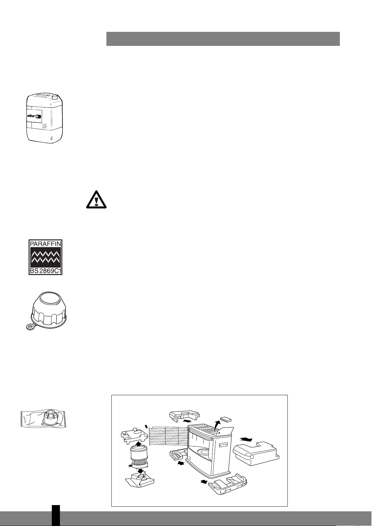
THE RIGHT FUEL
Only use Class C1 paraffin fuel in accordance with BS2869 Part two, or equivalent.
Your heater has been designed for use with high-quality water-free pure paraffin
oil, such as Zibro Extra or Zibro Kristal. Only fuels of this kind will ensure clean and
proper burning. Lower quality fuel may result in:
! excessive tar deposits on the glass fibre wick
! incomplete burning
! reduced heater lifetime
! smoke and/or smells
! deposits on the grid or mantle
Using the right fuel is therefore essential for safe, efficient, and comfortable use
of your heater.
Always refer to your local dealer for the right fuel for your heater.
Only the use of the
correct fuel will ensure
safe, efficient, and
comfortable use of your
heater.
4
52
A
The fuel cap cover can
be found at the rear of
the heater. This cover
allows you to keep your
hands clean when
opening the fuel tank.
Page 7

MANUAL
A INSTALLING THE HEATER
Carefully remove your heater from the box and check the contents.
I
n addition to the heater you also need to have:
! a manual fuel pump
! a transportation cap
! a fuel cap cover
! these directions for use
Keep the box and the packaging materials (Fig. A) for storage and/or
transportation.
Remove the other packaging materials:
! Remove the packaging material from the grill !. Lift the grill from the slot
(Fig. B) and pull it forward.
! Push the packing material on top of the combustion chamber " slightly
down and remove it (Fig. C). Remove the packaging materials from under
the combustion chamber as well (Fig. D).
! Put the combustion chamber back into its place. The combustion chamber
is positioned correctly when it can be smoothly moved a little to the left
and to the right by its handle # (Fig. E). Close the grill: Slightly lift it to
reposition it in its slot.
! Open the lid of the removable tank $ and remove the piece of cardboard.
Fill the removable tank as indicated in Section B.
Insert the batteries into their holder % at the back of the heater (Fig. F).
Ensure that the positive and negative poles match the + and - marks indicated
on the battery housing.
The floor should be firm and completely level.
Reposition the heater, when it is
not level. Do not correct the situation by placing books or other goods under the
heater.
Your heater is now ready for use.
B FILLING FUEL
Do not fill the removable tank in the living room, but in a more suitable place
(ther
e can always be some spillage). Follow the procedure below:
Make sure that the heater is switched off.
Open the lid $ and lift the removable tank & out of the heater (Fig. G).
Note: Some drops may leak from the tank. Put down the removable tank
(cap pointing upwards) and screw off the fuel cap using the fuel cap cover
(Fig. H).
21654
3
2
1
4
53
! ! ! ! ! !
G
B
C
D
E
H
F
Page 8
☞
T
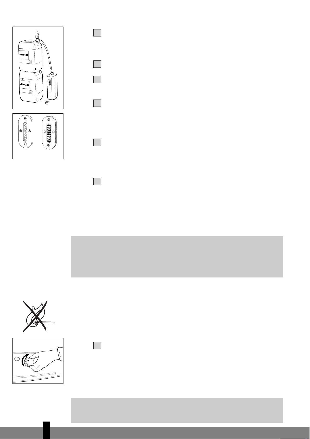
ake the manual fuel pump and insert the smooth, most rigid tube into the
jerrycan. Make sure that it is in a higher position than the removable tank
(Fig. I). Insert the ribbed hose into the opening of the removable tank.
Lock the valve on top of the pump (turn clockwise).
Squeeze the pump a few times, until fuel starts flowing into the removable
tank. As soon as this happens, there is no need to press any longer.
Check the removable tank fuel gauge
! while filling the tank (Fig. J). Stop
filling by loosening the valve on top of the pump (turn anti-clock-wise), once
the gauge indicates that the tank is full. Never overfill the tank, especially not
when the fuel is very cold (fuel expands when it heats up).
Let the remaining fuel in the pump flow back into the jerrycan and carefully
remove the pump. Carefully screw the fuel cap back on the tank using the
fuel cap cover. After use, re-store the cover at the rear of the heater. Clean
off any spilled fuel.
Check whether the fuel cap is straight and tightened properly. Reinstall the
removable tank in the heater (cap down). Close the lid.
C IGNITING THE HEATER
A new heater may give off some smells for a short while, when it is used for the
first time. You should therefore provide extra ventilation or ignite the heater outs-
ide the living room.
When you use the heater for the first time, first put the filled removable tank into
place, and then wait approximately 30 minutes before you ignite the heater. This
allows the glass fibre wick to soak up the fuel. Follow the same procedure when you
have completely burnt up all fuel from the tank, and after the glass fibre wick has
been replaced.
Before igniting the heater, always check the fuel indicator " to see whether the
removable tank needs filling up (Green=full, Red=empty).
Always ignite the heater with
the knurled wick adjustment knob
#. Never use
matches or a cigarette lighter.
Follow the pr
ocedure below:
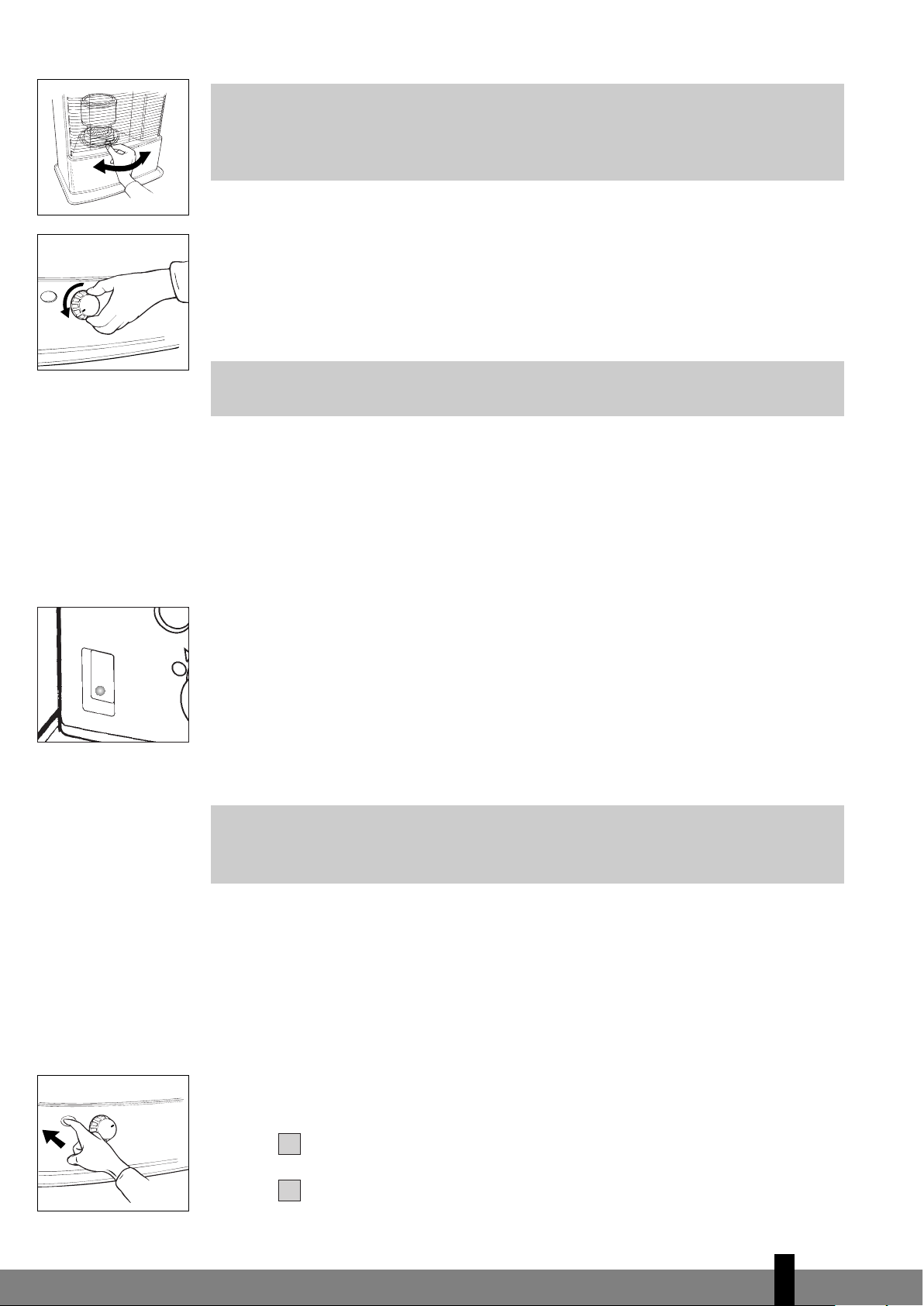
Turn the knurled wick adjustment knob # clockwise to its stop (Fig. K). If you
apply more pressure you may turn it slightly further; however, it will automatically
return to the start position. When you have set the wick to its highest position,
this action will automatically activate the safety device.
When you have ignited the heater and it shuts off again shortly after, the batteries
need to be r
eplaced. It is best to use new alkaline batteries (4x D-size).
If the heater has been used only a few times and the wick adjustment knob is not
locked, first turn the wick adjustment knob (Fig. L) completely left, before putting
the wick in the highest position for ignition (Section C).
187
6
543
4
54
J
I
empty full
K
☞
Page 9
4
55
☞☞
E
☞
M
A
fter having ignited the heater, always check whether the combustion
chamber ! is level, by sliding it slightly to the left and the right by its handle "
(Fig. E). This should be a smooth movement. If the combustion chamber is not
level, this will cause smoke and soot to develop.
D BURNING OF THE HEATER
After you have ignited the heater, it will take 10 to 15 minutes before you can
check whether the heater is burning well. Too high a flame may cause smoke and
soot, whereas too low a flame causes smells. The page opposite the folding page
shows the minimum and maximum permissible burning heights of the flame (Fig. R).
If the flame remains low after the adjustment, the wick height must be
adjusted (refer to Section F).
Burning that is too low may be caused by:
! insufficient fuel (fill the tank)
! poor fuel quality (contact your dealer)
! insufficient ventilation (put window or door ajar)
! wastage of the wick (contact your dealer or replace the wick,
refer to section M)
When there is insufficient ventilation in the room, an intermittent buzzer will be
heard and the VENT lamp (Yellow) will be lit. When this signal is given, ensure that
the ventilation of the room is improved (e.g. by opening a door or window a little
more) to avoid that the heater shuts off. When the ventilation of the room is
improved, the VENT lamp and buzzer will be deactivated. When there is still insuf-
ficient ventilation, the heater shuts off automatically. After improving the ventila-
tion of the room (e.g. by opening a door or window a little more), the heater can
be ignited again.
This heater is fitted with a safety system that ensures that it switches off if you
lift the exchange tank out of the heater for more than 5 seconds. To switch the
heater on again, put the exchange tank back and follow the steps in
section C.
E SWITCHING OFF THE HEATER
Push the OFF-button #. The flame will extinguish after a little while.
F ADJUSTING THE WICK HEIGHT
After a period of time the combustion may no longer be high enough (Section D). In
that case you can adjust the wick height to improve the flame. To do this, the heater
must have been switched of
f. Follow the procedure below:
Push the OFF button
# (Fig. M).
Pull the knurled wick adjustment knob
$ of
f the heater
, so the wick height
lock
% will be visible.
2
1
S
V
E
N
T
.
L
Page 10
T
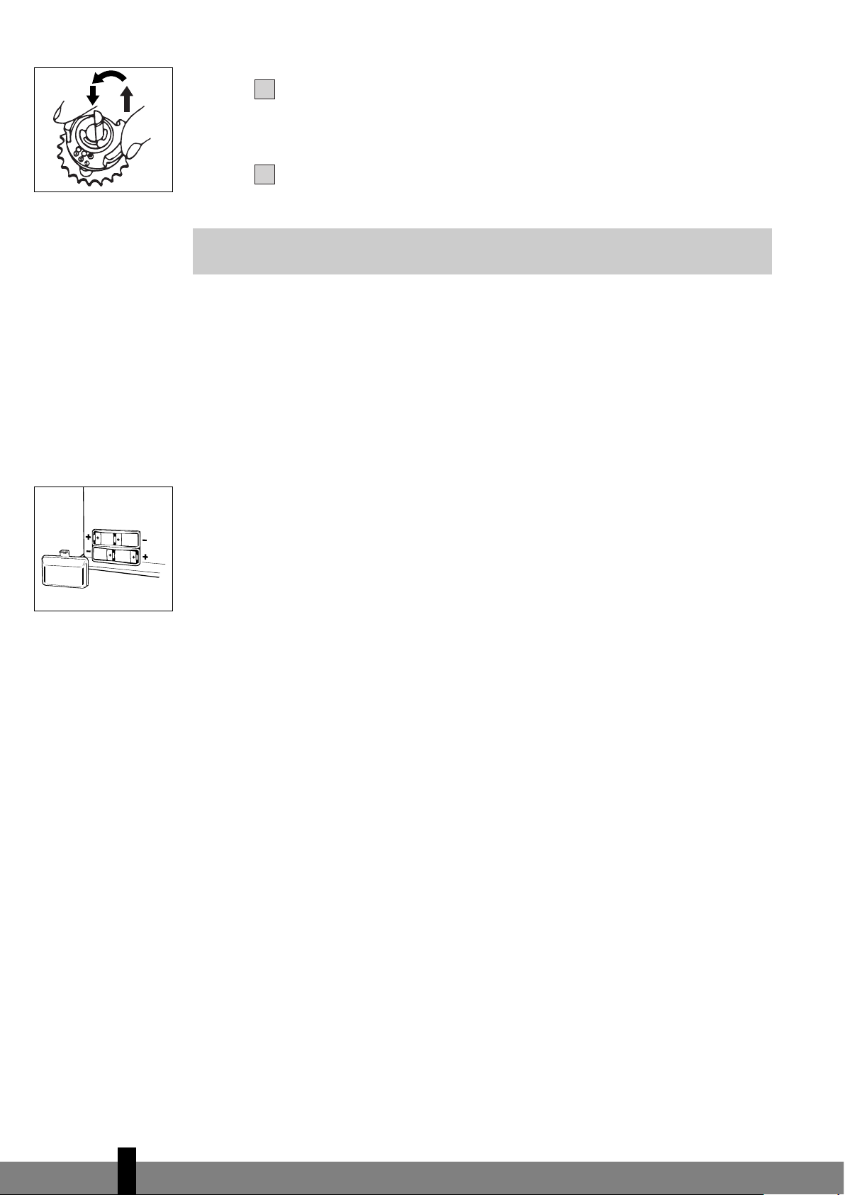
ake the plastic collar between your thumb and index finger and pull it out.
Turn t he co lla r up one s tep , to either p osition 2 or 3 (Fig. N). C are fully push
the collar back, so the pin engages in the recess.
Carefully reinstall the knurled wick adjustment knob. This can be done in one
w
ay only - check the rear of the cap for the correct position.
If adjustment of the wick height does not have the required effect, let the
heater burn until all fuel has been used up
(Section H).
If the flame height is still too low and the wick is set on position 3, then contact your
dealer,
or replace the wick, refer to section M.
If the flame gets too high after adjus-
ting (Fig R), the wick height lock should be placed one position lower again.
Otherwise smoke or soot may be caused.
G MALFUNCTION, CAUSES AND SOLUTIONS
If any malfunctioning cannot be solved from the directions below, please contact
your dealer.
THE HEATER DOES NOT IGNITE
! The batteries are not positioned correctly in the holder. Check (Fig. O).
! There is not enough power left in the batteries for the ignition. Replace (Fig. O).
! You have run out of fuel from the tank or the wick has been replaced.
After having refilled and replaced the removable tank, wait for 30 minutes
before igniting the heater.
IRREGULAR FLAME AND/OR SOOT AND/OR SMELLS
! The combustion chamber ! has not been positioned correctly.
Use the handle " to put it level, until you can easily slide it slightly to the left
and to the right and the chamber is level.
! You are using fuel which is past its ‘use by’ date.
Start every heating season with fresh fuel.
! You are using the incorrect type of fuel.
Refer to THE RIGHT FUEL (See Section ’What you need to know in advance’).
! Dust has gathered in the lower part of the heater.
Contact your dealer.
! Wick position wrong.
See Section F.
THE HEATER SLOWLY EXTINGUISHES
! The removable tank is empty.
See Section B.
! The fuel filter is contaminated by water
.
Dry the fuel filter (Section H, Fig. P).
! The lower reservoir is contaminated by water.
Contact your dealer
.
! The wick has hardened on the upper side.
Burn the heater until all fuel is used (Section H). Use the right fuel.
! You are using fuel which is past its ‘use by’ date.
Star
t ever
y heating season with fr
esh fuel.
THE HEA
TER REMAINS BURNING LOW
! W
ick position too low
.
4
3
4
56
☞
N
O
Page 11

R
einstall the wick height lock (Section F).
! Before you refilled the tank, the heater had burnt up almost all the fuel.
After having refilled and replaced the removable tank, wait for 30 minutes
before igniting the heater.
! You are using the incorrect type of fuel.
R
efer to THE RIGHT FUEL (See Section ’What you need to know in advance’).
! The room is insufficiently ventilated.
Leave a window or a door wide open for a while.
THE HEATER IS BURNING TOO HIGH
! You are using an incorrect, too volatile type of fuel.
Refer to THE RIGHT FUEL (See Section ’What you need to know in advance’).
! Wick position too high.
Reinstall the wick height lock (Section F).
H MAINTENANCE
Your heat er need s hard ly any main te na nc e. It is, howe ve r, impo rt an t that you
remove dust and stains in time with a damp cloth, because otherwise these may
cause stains that are hard to remove. Under normal conditions, only two
components are subject to wear:
1. THE BATTERIES
You m ay rep lac e t he bat ter ies yo urs elf . Do n ot dis pos e o f o ld bat ter ies al ong wi th
the other domestic waste. Follow the locally applicable regulations regarding the
disposal of domestic chemical waste.
2. THE WICK
To extend the glass fibre wick life, you must occasionally let the heater burn until
the tank is completely emptied and the heater extinguishes by itself. Do this when
you notice that the flame is weakening. The burn-out will cause some smells, so it
is recommended that you take the heater outside of the living room.
THE FUEL FILTER
Check the fuel filter regularly as well.
Remove the removable tank ! from the heater and take out the fuel filter (Fig. P).
Some drops of fuel may spill from the filter; keep a cloth at hand. Turn the fuel
filter upside down and clean it from all dirt deposits by tapping it on a hard
surface.
(Never clean it with water!) Reposition the fuel filter in the heater.
Do not remove any heater components yourself. Always contact your dealer for
repairs.
Let the heater cool down first, before you start any maintenance or service work.
4
57
☞
☞
fuel filter
P
Page 12

I STORAGE (END OF THE HEATING SEASON)
We recommend that you burn up all the fuel in the fuel tank at the end of the heating
season and store the heater properly. Follow the procedure on the next page:
Ignite the heater outside the living room and let it burn until all fuel is used.
Let the heater cool down.
Clean the heater with a damp cloth and then dry it with a dry cloth.
Remove the batteries from the holder
! and store them in a dry place.
Clean the fuel filter (refer to section H).
Store the heater in a dust-free place, if possible in its original packaging.
Unused fuel cannot be used for the next heating season. If there is still some
fuel left, do not throw it away, but dispose of it in accordance with the local
regulations for the disposal of domestic chemical waste. Always start the new
heating season with fresh fuel. When you start re-using the heater, follow the
instructions again (starting from Section A and as specified).
J TRANSPORTATION
Take t he fo llo wing mea sures to avoi d fue l l eakag e during the tra nspor tat ion o f
the heater:
Let the heater cool down.
Remove the removable tank
" from the heater and remove the fuel filter
(Fig. P). Some drops may leak from the filter; keep a cloth at hand. Store the
fuel filter and the removable tank outside the heater.
Place the transpor
tation cap into the position of the fuel filter (Fig. Q).
Pr
ess it tight.
Always move the heater in an upright position.
K SPECIFICATIONS
Ignition electrical Dimensions (mm) width 562
Fuel paraffin (including base plate) depth 279
Capacity (kW)
*
3.00
height 502
Suitable space (m3)
**
55-110 Accessories: manual fuel pump
Fuel consumption (l/hr)
*
0.313 fuel cap cover,
Fuel consumption (g/hr)
*
250
transportation cap
Burning time per tank (hr)
*
17.5 Required batteries 4 x LR20, MN1300
Capacity removable tank (litres) 5.5 1.5V, Size D
Weight (kg) 11.5 Wick type C
Monitoring of the quality of ventilation (air r
enewal):
Dir
ect measur
ement of the CO
2
level (NDIR CO2sensor E-Guard#).
*
At maximum setting
** Specified values are indicative
432
1
654
321
4
58
Transportation cap
fuel filter
P
Q
Page 13

L WARRANTY P ROV ISI ONS
Your he at er c omes w it h a 48 -mon th w ar ra nt y star ti ng o n th e date o f pu rc ha se.
Within this period all defects in material or workmanship will be repaired without
any charge. The following provisions shall apply regarding this warranty:
W
e expressly dismiss all other claims for damages, including consequential
damages.
Any repairs or replacements of components within the term of warranty will
not result in an extension of the term of warranty.
The warranty will no longer apply, when the heater has been modified,
non-original parts have been used, or when it is repaired by third parties.
The warranty will not apply to parts that are subject to normal wear, such as
the batteries, the ignition coil, the wick and the manual fuel pump.
The warranty will only apply, when you present the original, dated proof of
purchase, provided no changes have been made to it.
The warranty will not apply to damages caused by actions not in compliance
with the Directions for Use, neglect, and the use of an incorrect type of fuel,
or fuel past its use-by date. The use of incorrect fuel can even be dangerous*.
Transp ortation costs a nd the r isks inv olved du ring the tran spo rtati on of th e
heater or heater components will always be the responsibility of the
purchaser.
In order to avoid unnecessary costs, we recommend that you always read the
’Directions for Use’ carefully first. In case they offer no solution, please take the
heater to your dealer for repair.
* Highly inflammable substances may induce uncontrollable burning, causing flames to break out. Should this
happen, never try to move the heater, but always switch off the heater immediately (refer to Section E). In cases
of emergency you may use a fire extinguisher, but only a type B extinguisher: a carbon dioxide or powder
extinguisher.
10 TIPS FOR SAFE USE
1 Make sur
e that children are always aware of the presence of a burning
heater.
2 Do not move the heater when it is burning or still hot. Do not refill nor
service the heater when it is burning or still hot.
3 Position the front of the heater at a minimum distance of 1.5 metres
fr
om walls, curtains, and furniture.
4 Do not use the heater in dusty rooms or in very draughty places. In
both cases you will not have optimum burning.
5 Switch off the heater, before you go to sleep.
6 Stor
e and move fuel only in suitable tanks and jerrycans.
7 Make sure that the fuel is not exposed to heat or extreme temperature
changes. Always store the fuel in a cool, dry and dark place (sunlight
will af
fect the quality).
8 Never use the heater in places where harmful gasses or fumes may be
pr
esent (e.g. exhaust gasses or paint fumes).
9 The top plate of the heater becomes hot. Do not cover the heater
(ther
e is a risk of fir
e). A
void any concact with the top plate and grille.
10 Always make sure that there is sufficient ventilation.
76543
2
1
4
59
150 cm
50 cm
50 cm
20 cm
100 cm
Page 14

REPLACEMENT OF THE WICK
M ENSURE THAT THE HEATER IS OFF AND COMPLETELY
COOL BEFORE STARTING TO REPLACE THE WICK.
Open the lid and remove the removable tank.
Remove the batteries from the battery holder.
Open the front grill. Remove the combustion chamber
from the heater. Close the grill.
Pull the knurled wick adjustment knob off the heater.
Unscrew the three cabinet screws on the back and sides
of the heater. Pull the cabinet forward slightly, and then
remove it from the base plate.
Unscrew the four wing nuts from the wick holder.
Lift up the wick holder and the wick mechanism.
Squeeze the wick to loosen the three wick pins and
remove the wick from the wick holder. Ensure that you
are wearing gloves and that you have a container in
which to put the old wick.
Put the wick holder back into position in such a way
that the holes in the wick holder are directly above the
inner sides of the recesses in the burner. Ensure that the
holes are facing down.
Fold a new wick and place it in the wick holder. Push
the three wick pins into the wick holder holes, and the-
refore also into the recesses inside the burner. Push the
wick with the wick holder up into the recesses as far as
possible. Push the pins firmly until you hear a clicking
sound. Ensure that the wick holder does not bend!
10
9
87654
3
2
1
4
60
55bb
11
44
99
11 00aa
88
11 00bb
33
22
55aa
66
77
Page 15

4
61
Put the wick holder and the wick mechanism back into
position.
Screw the four wing nuts hand tight.
Place the knurled wick adjustment knob on the wick
mechanism. Turn the knob as far to the right as possi-
ble. Press the off switch. Check that the wick can be
lowered completely. Repeat this check a number of
times. If the wick cannot be lowered completely it has
not been placed correctly. If this is the case, repeat the
procedure from 10.
Remove the knurled wick adjustment knob and adjust
the wick position to 1.
Put the cabinet back into position and tighten the three
screws. Put the knurled adjustment knob back into
position. Now put the combustion chamber back into
position. Check that it is level by sliding it slightly to the
left and the right by its handle. Close the grill.
Put the filled removable tank back into position. Put
the batteries into the battery holder (ensure that the
positive and negative poles match the + and – marks
indicated on the battery housing). Wait 30 minutes
after replacing the tank and batteries before using the
heater.
16
1514131211
11 11
11 55aa
11 55cc
11 66aa
11 44aa
11 66bb
11 22
11 33aa 11 33bb
11 44bb
11 55bb
11 55dd
Page 16

! ! ! ! ! ! ! ! ! ! ! ! ! ! ! ! ! ! ! ! ! ! ! ! ! ! ! ! ! ! ! ! ! ! ! ! ! ! ! ! ! ! ! ! ! !
"
R
✗✓✗
Page 17

! "
#
$
%
&
'
(
)
*
+
,
#
!
"
Page 18

PVG T
raffic avg©080626 man_R617E
Printed in Japan
7447000903
Rev. 7/08
DISTRIBUTED IN EUROPE BY PVG INTERNATIONAL b.v.
i ÖSTERREICH
P
VG Austria VertriebsgmbH
Salaberg 49
3
350 HAAG
tel: +43 7434 44867
fax: +43 7434 44868
email: pvgaustria@zibro.com
e BELGIË
PVG Belgium NV/SA
Industrielaan 55
2
900 SCHOTEN
tel: +32 3 326 39 39
fax: +32 3 326 26 39
email: pvgbelgium@zibro.com
q SCHWEIZ
PVG Schweiz AG
Salinenstrasse 63
4133 PRATTELN
tel: +41 61 337 26 51
fax: +41 61 337 26 78
email: pvgint@zibro.com
2 DEUTSCHLAND
PVG Deutschland GmbH
Siemensstrasse 31
47533 KLEVE
tel: 0800 - 9427646
fax: +31 (0)412 648 385
email: pvgdeutschland@zibro.com
6 DANMARK
Appliance A/S
Blovstroed Teglvaerksvej 3
DK-3450 ALLEROED
tel: +45 70 205 701
fax: +45 70 208 701
email: appliance@appliance-group.com
5 ESPAÑA
PVG España S.A.
Pol. Ind. San José de Valderas II
Comunidad ”La Alameda”
C/ Aur
ora Boreal, 19
28918 LEGANÉS (Madrid)
tel: +34 91 611 31 13
fax: +34 91 612 73 04
email:
pvgspain@zibr
o.com
3 FRANCE
PVG France SARL
4, Rue Jean Sibélius
B.P. 185
76410 SOTTEVILLE SOUS LE VAL
tel:
+33 2 32 96 07 47
fax: +33 0 820 34 64 84
email: pvgfrance@zibro.com
SUOMI
Appliance Finland Oy
Piispantilankuja 6C
02240 ESPOO
tel:
+358 9 4390 030
fax: +358 9 4390 0320
email: appliance@appliance-group.com
FFIINN
4 UNITED KINGDOM
S
cott Brothers Ltd.
The Old Barn, Holly House Estate
C
ranage, Middlewich, CW10 9LT UK
tel.: +44 1606 837787
fax: +44 1606 837757
email: sales@scottmail.co.uk
> ITALIA
P
VG Italy SRL
Via Niccolò Copernico 5
50051 CASTELFIORENTINO (FI)
t
el: +39 571 628 500
fax: +39 571 628 504
email: pvgitaly@zibro.com
u NORGE
Appliance Norge AS
Vogellunden 31
1394 NESBRU
tel: +47 667 76 200
fax: +47 667 76 201
email: appliance@appliance-group.com
1 NEDERLAND
PVG International B.V.
P.O. Box 96
5340 AB OSS
tel: +31 412 694 694
fax: +31 412 622 893
email: pvgnl@zibro.com
9 PORTUGAL
Gardena, Lda
Recta da Granja do Marquês
ALGUEIRÃO
2725-596 MEM MARTINS
tel: + 35 21 92 28 530
fax: + 35 21 92 28 536
email: pvgint@zibro.com
: POLSKA
PVG Polska Sp. z. o. o.
ul. Kościelna 110
26-800 Bia
łobrzegi
tel: +48 48 613 00 70
fax:
+48 48 613 00 70
email: pvgpoland@zibro.com
= SVERIGE
Appliance Sweden AB
Sjögatan 6
25225 HELSINGBORG
tel: +46 42 287 830
fax:
+46 42 145 890
email: appliance@appliance-group.com
y SLOVENIJA
Monteko d.o.o.
Neubergerjeva 4
1000 Ljubljana
tel:
+386 (0)1 437 1273
fax: +386 (0)1 437 1273
email: info@zibro.si
TURKEY
PVG Is›tma Klima So¤utma Ltd.fiti.
T
epekule is merkezi
Anadolu Cad. No: 40 K:3 D:306
35010 BAYRAKLI/IZMIR
tel: + 90 232 461 51 01
fax:
+ 90 232 461 51 85
email: pvgturkey@zibro.com
TTRR
Page 19

R 617 E
2
14
26
38
50
62
74
MANUEL D'UTILISA
TION
GEBRAUCHSANWEISUNG
BRUGSANVISNING
INSTRUCCIONES DE USO
OPERATING MANUAL
ISTRUZIONI D’USO
GEBRUIKSAANWIJZING
3
2
6
5
4
>
1
Page 20

3
A
FAQ AFNOR CERTIFICATION 11, AVENUE FRANCIS DE PRESSENSE
93571 SAINT-DENIS LA PLAINE CEDEX
FICHE INFORMATIVE
La marque NF garantit
la qualité de cet article
suivant les normes françaises
et Règles de certification
de l’application NF 128
CONFORME A LA NORME NF D 35-300 ET AUX SPECIFICATIONS
COMPLEMENTAIRES DEFINIES PAR LES REGLES
DE CERTIFICATION DE L’APPLICATION NF 128
PRINCIPALES CARACTERISTIQUES CERTIFIEES:
• Sécurité du dispositif d’allumage
• Débit calorifique
• Efficacité des dispositifs de sécurité
• Stabilité
• Contrôle de la teneur en NOxdans les produits de combustion
• Contrôle de la qualité de la combustion (absence de CO)
• Endurance
• Intermittence
CONSEILS D’UTILISA
TION ET D’ENTRETIEN
Se reporter à la notice jointe à l’appareil et à la plaque de sécurité sur
l’appareil
Référence et numéro de lot ou de série de l’article : se reporter au produit
Distributed in Europe by:
PVG International B.V.
P.O.Box 96, 5340 AB OSS
Pays-Bas Tél.: +31 (0) 412 694670
En cas d’insatisfaction, consultez d’abord :
En France: PVG France SARL
4, Rue Jean Sibélius, B.P
. 185
76410 SOTTEVILLE SOUS LE VAL
Tél.: 02.32.96.07.47 – Fax: 02.32.96.07.77
Si une difficulté subsistait, vous pouvez écrire au LNE
LABORATOIRE NATIONAL DE MÉTROLOGIE ET D’ESSAIS
Division Certification plurisectorielle
1, Rue Gaston Boisier - 75724 PARIS CEDEX 15
CHAUFFAGES MOBILES
A COMBUSTIBLE LIQUIDE
NF 128 02 / 01
Page 21

3
FICHE INFORMATIVE
La marque NF garantit
la qualité de cet article
suivant les normes françaises
et Règles de certification
de l’application NF 128
CONFORME A LA NORME NF D 35-300 ET AUX SPECIFICATIONS
COMPLEMENTAIRES DEFINIES PAR LES REGLES
DE CER
TIFICATION DE L’APPLICATION NF 128
PRINCIP
ALES CARACTERISTIQUES CERTIFIEES:
• Adaptation au(x) convecteur(s) pour lesquels la mèche est revendiquée
• Débit calorifique pour ce(s) convecteur(s)
• Contrôle de la qualité de la combustion
CONSEILS D’UTILISA
TION ET D’ENTRETIEN
Se reporter à la notice jointe à l’appareil de chauffage et aux indications
figurant sur l’emballage de la mèche.
Référence et numéro de lot ou de série de l’article : se reporter au produit
Distributed in Europe by:
PVG International B.V.
P.O.Box 96, 5340 AB OSS
Pays-Bas Tél.: +31 (0) 412 694670
En cas d’insatisfaction, consultez d’abor
d :
En France: PVG France SARL – 4, Rue Jean Sibélius, B.P
. 185
76410 SOTTEVILLE SOUS LE VAL – Tél.: 02.32.96.07.47 – Fax:
02.32.96.07.77
Si une dif
ficulté subsistait, vous pouvez écrire au LNE
LABORATOIRE NATIONAL DE MÉTROLOGIE ET D’ESSAIS
Division Certification plurisectorielle
1, Rue Gaston Boisier - 75724 PARIS CEDEX 15
NF 128 02 / 01
AFAQ AFNOR CERTIFICATION 11, AVENUE FRANCIS DE PRESSENSE
9
3571 SAINT-DENIS LA PLAINE CEDEX
Page 22

Sehr geehrte Kundin, sehr geehrter Kunde,
herzlichen Glückwunsch! Sie sind jetzt der stolze Besitzer eines Zibro, der Top-
Marke transportabler Kaminöfen. Sie haben sich für ein absolutes
Qualitätsprodukt entschieden, an dem Sie noch viele Jahre Ihre Freude haben
werden, vorausgesetzt, Sie benutzen den Kaminofen verantwortungsvoll. Lesen
Sie deswegen zuerst diese Gebrauchsanweisung aufmerksam durch, um so eine
optimale Lebensdauer Ihres Zibro zu garantieren.
Im Namen des Herstellers bieten wir Ihnen 48 Monate Garantie auf alle
eventuell auftretenden Material- und Herstellungsfehler.
Wir wünschen Ihnen viel Wärme und Komfort mit Ihrem Zibro.
Mit freundlichen Grüßen
PVG International b.v.
Abteilung Kundendienst
1 LESEN SIE ZUERST DIE GEBRAUCHSANWEISUNG.
2 WENDEN SIE SICH IM ZWEIFELSF
ALL AN IHREN HÄNDLER.
3 VOR DEM LESEN DER GEBRAUCHSANWEISUNG BITTE DAS LETZTE BLATT AUFFALTEN. ! ! !
2
14
Page 23

BENUTZUNG
KURZ ZUSAMMENGEFASST
Nachfolgend sind in groben Zügen die Schritte
angegeben, die zur Inbetriebnahme Ihres Kaminofens ausgeführt werden müssen. Detaillierte
Beschreibung der Handlungen entnehmen Sie bitte
der GEBRAUCHSANWEISUNG (Seite 17 ff).
• Das erste Mal wird Ihr Kaminofen während des
Brennens noch ‘neu’ riechen.
• Lagern Sie den Brennstoff an einem kühlen,
dunklen Ort.
• Brennstoff altert. Beginnen Sie jede Heizsaison
mit neuem Brennstoff.
• Wenn Sie Zibro Extra oder Zibro Kristal benutzen,
können Sie sich auf die Qualität des Brennstoffs
verlassen.
• Wenn Sie zwischen den einzelnen Sorten
wechseln, müssen Sie den Kaminofen erst vollständig leer brennen lassen.
WICHTIGE
EINZELTEILE
Abschalt-Taste
Drehregler
Batteriefach
Brennkammer
Handgriff
Brennkammer
Brennstoffanzeige
Gitter
Deckel
Brennstofftank
Brennstofftank
Brennstoffanzeige
Br
ennstofftank
Dochthöhe
Spark-Zündung
Überwachungssys-
tem für Luftqualität
Informationsdisplay
(E-Guar
d)
!
"
#
$
%
&
'
(
)
*
+
,
-
.
! ! ! ! ! ! ! ! ! ! ! ! ! ! ! ! ! ! ! ! ! ! !
Entfernen Sie das gesamte Verpackungsmaterial
(siehe Kapitel A, Abb. A).
Befüllen Sie den Brennstofftank ) und warten Sie 30 Minuten
bevor Sie den Kaminofen starten
(siehe Kapitel B, Abb. I).
Geben Sie die Batterien in das Batteriefach /
(siehe Kapitel A, Abb. F).
Überprüfen Sie, ob die Brennkammer 0 gerade steht
(siehe Kapitel A, Abb. E).
Starten Sie den Kaminofen, indem Sie den Drehregler " langsam nach
rechts drehen, bis er sich nicht weiter drehen läßt
(siehe Kapitel C, Abb. K).
Nach dem Starten des Ofens dauert es 10 bis 15 Minuten bevor
Sie sehen, ob der Ofen richtig brennt (siehe Kapitel D).
Schalten Sie den Kaminofen aus (siehe Kapitel E).
1
2
3
4
5
6
7
2
15
Page 24

Diesen Transport-
verschluß finden Sie im
Verpackungskarton. Nur
hiermit kann der
Kaminofen nach
Benutzung problemlos
transportiert werden.
Bewahren Sie den
Verschluß also gut auf!
WICHTIG ZU WISSEN
JEDERZEIT AUSREICHEND VENTILIEREN
Dieses Heizgerät ist mit einem System zur Kontrolle der Luftbeschaffenheit ausgerüstet. Wird der Raum unzureichend belüftet oder das Heizgerät in einem zu
kleinen Raum eingesetzt, schaltet sich das Heizgerät automatisch ab. Um eine
komfortable und sichere Beheizung zu erreichen, sorgen Sie für eine ausreichende
Belüftung.
Hinweis: Um ein unerwartetes Abschalten zu vermeiden, empfehlen wir, eine Tür
oder ein Fenster einen Spalt offen stehen zu lassen, wenn das Heizgerät in Betrieb ist.
Jedes Modell benötigt eine bestimmte minimale Raumgröße, um den
Kaminofen
sicher, ohne zusätzliche Ventilation besonder gut betreiben zu können (siehe Kapitel K).
Wenn der betreffende Raum kleiner als der angegebene Minimumwert ist, muß
dafür gesorgt werden, daß immer ein Fenster oder eine Tür einen Spalt breit offen
bleibt (ca. 2,5 cm). Dies ist ebenfalls empfehlenswert bei Räumen, die besonders
gut isoliert oder zugfrei sind und/oder über 1500 m liegen. Benutzen Sie den
Kaminofen nicht in Keller- oder anderen unterirdisch gelegenen Räumen.
DER SAFE TOP
Der Ofen ist versehen von einem Safe T
op. Dieser verringert die Temperatur an der
Oberseite des Ofens. Sollte die Oberseite berührt werden, so wird das Risiko auf
schwere Verletzung erheblich verringert. Berücksichtigen Sie aber, daß die
Oberseite immer noch heiß wird.
Berühren Sie die Oberseite und das Gitter nicht.
DER RICHTIGE BRENNSTOFF
Ihr Kaminofen wurde für die Benutzung von wasserfreiem, sauberem Petroleum
hoher Qualität, wie Zibro Extra oder Zibro Kristal, entwickelt. Nur dieser
Br
ennstoff sorgt für eine saubere und optimale Verbrennung. Brennstoff
geringerer Qualität kann zu folgenden Problemen führen:
! übermäßige Ablagerung auf dem Docht
! unvollständige Verbrennung
! verkürzte Lebensdauer von Docht und Kaminofen
! Rauch und/oder Geruch
! Niederschlag auf dem Gitter oder Gehäuse
Der richtige Br
ennstof
f ist also wichtig für einen sicher
en, ef
fizienten und
komfortablen Gebrauch Ihres Kaminofens.
Infor
mieren Sie sich bei Ihrem Händler in Ihrer direkten Umgebung über den
richtigen Brennstoff für Ihren Kaminofen.
Nur mit dem richtigen
Brennstoff ist eine
sichere, effiziente und
komfortable Benutzung
Ihres Kaminofens
gewährleistet.
2
16
A
Der Tankdeckelöffner
befindet sich an der
Rückseite des Kamin-
ofens. Mit Hilfe dieses
T
ankdeckelöffners
bleiben Ihr
e Hände beim
Öf
fnen des Brennstoff-
tanks sauber.
Page 25

GEBRAUCHSANWEISUNG
A DIE INSTALLATION DES KAMINOFENS
Nehmen Sie den Kaminofen vorsichtig aus dem Karton und kontrollieren Sie
den Inhalt auf Vollständigkeit.
Außer dem Kaminofen muß folgendes vorhanden sein:
! eine Syphonpumpe
! ein Transportverschluß
! ein Tankdeckelöffner
! diese Gebrauchsanweisung
Bewahren Sie den Karton und das Verpackungsmaterial (Abb. A) zwecks
Lagerung und/oder Transport auf.
Entfernen Sie das übrige Verpackungsmaterial:
! Entfernen Sie das Stückchen Verpackungsmaterial vom Gitter '.
Heben Sie das Gitter aus der Kerbung (Abb. B) und ziehen Sie es nach vorn.
! Ziehen Sie den Kar
ton an der Oberseite der Brennkammer
0 vorsichtig
heraus und entfernen sie ihn (Abb. C). Nehmen Sie die Brennkammer aus
dem Kaminofen und entfernen Sie auch das Verpackungsmaterial unter der
Br
ennkammer (Abb. D).
! Setzen Sie die Brennkammer wieder ein. Die Brennkammer steht richtig,
wenn sie sich ohne Schwierigkeiten mit dem Handgriff % etwas nach links
und rechts verschieben lässt (Abb. E).
! Schließen Sie das Gitter: leicht anheben, um es wieder in die Kerbung
einrasten zu lassen.
! Öffnen Sie den Deckel des Brennstofftanks ( und entfernen Sie das
Stückchen Karton.
Befüllen Sie den Br
ennstofftank wie in Kapitel B beschrieben.
Legen Sie die Batterien in das dafür bestimmte Fach / an der Rückseite des
Kaminofens (Abb. F). Achten Sie dabei auf die + und - Pole.
Der Boden muß stabil und waagerecht sein. Stellen Sie den Kamin an eine
andere Stelle, falls er nicht waagerecht steht. Versuchen Sie nicht durch
Unterlage von Bücher
n oder ähnlichem den Stand zu kor
rigier
en.
Ihr Kaminofen ist jetzt betriebsber
eit.
B DAS BEFÜLLEN MIT BRENNSTOFF
Füllen Sie den Brennstofftank nicht im Wohnraum, sondern an einer dazu
geeigneten Stelle (falls etwas verschüttet wird). Gehen Sie wie folgt vor:
Der Kaminofen sollte ausgeschaltet sein.
Öf
fnen Sie den Deckel
( und ziehen Sie den Br
ennstofftank
) aus dem
Kaminofen (Abb. G). Achtung: der Tank kann kurz nachtropfen. Stellen Sie
den Brennstofftank ab (mit dem Tankverschluß nach oben) und drehen Sie
den Tankverschluß mit Hilfe des Tankdeckelöffners auf (Abb. H).
2
165
432
1
2
17
! ! ! ! ! !
G
B
C
D
E
H
F
Page 26

2
18
K
J
I
leer voll
☞
☞
Den glatten, steifen Schlauch der Syphonpumpe in den Kanister stecken. Das
Befüllen ist einfacher, wenn der Kanister höher steht als der Brennstofftank
(Abb. I). Den geriffelten Schlauch stecken Sie dann in die Öffnung des
Brennstofftanks.
Den weißen Knopf oben auf der Pumpe zudrehen (nach rechts).
Einige Male die Pumpe drücken, bis der Brennstoff in den Brennstofftank
fließt. Sobald dies der Fall ist, brauchen Sie nicht mehr zu drücken.
Achten Sie während des Füllvorgangs auf die Brennstoffanzeige des
Brennstofftanks
* (Abb. J). Wenn Sie sehen, daß der Tank fast voll ist, stellen
Sie den Füllvorgang ein. Hierzu drehen Sie den weißen Knopf oben auf der
Pumpe wieder auf (nach links). Den Tank niemals zu voll füllen. Vor allem
nicht, wenn der Brennstoff sehr kalt ist (Brennstoff dehnt sich aus, wenn er
wärmer wird).
Lassen Sie den Brennstoff, der sich noch in der Pumpe befindet, in den
Kanister zurückströmen und entfer
nen Sie die Pumpe vorsichtig. Schrauben
Sie den Tankverschluß mit Hilfe des Tankdeckelöffners wieder sorgfältig auf
den Tank. Nach Gebrauch können Sie den Tankdeckelöffner wieder an der
Rückseite des Zibro befestigen. Wischen Sie eventuell verschütteten
Brennstoff weg.
Kontrollieren Sie, ob der Tankverschluß gerade sitzt und fest angezogen ist.
Setzen Sie den Brennstofftank wieder in den Kaminofen ein (Tankverschluß
nach unten). Schließen Sie den Deckel.
C DAS STARTEN DES KAMINOFENS
Ein neuer Ofen verursacht zu Beginn etwas Geruch. Sorgen Sie deswegen für zusätzliche Ventilation oder starten Sie den Ofen das erste Mal außerhalb des Wohnraumes.
Wenn Sie den Kaminofen zum ersten Mal benutzen, müssen Sie nach dem
Einsetzen des Brennstofftanks ca. 30 Minuten warten, bevor Sie den Ofen
starten, damit sich der Docht mit Brennstoff vollsaugen kann. Dies trifft auch
zu, wenn Sie den Kaminofen vollständig leer gebrannt haben,
beziehungsweise nach Austausch des Dochtes.
Achten Sie vor dem Starten des Kaminofens darauf, daß sich noch genügend Brennstof
f im T
ank befindet (mit Hilfe der Br
ennstof
fanzeige
&).
Starten Sie den Kaminofen immer über die Drehregler 1.
Niemals Streichhölzer oder ein Feuerzeug benutzen.
Hierbei gehen Sie wie folgt vor:
Dr
ehen Sie den Dr
ehr
egler
1 nach r
echts bis zum Anschlag (Abb. K).
Mit einem gewissen Druck könnten Sie den Drehregler dann noch etwas
weiter drehen, er federt dann jedoch von selbst wieder zurück.
So wir
d der Docht auf die höchste Position eingestellt und das
Sicherungssystem aktiviert.
Haben Sie das Heizgerät gestar
tet und es schaltet sich kur
z danach wieder aus, müssen
die Batterien ausgetauscht wer
den. Am besten ver
wenden Sie dazu neue Alkaline-
Batterien (4 x Größe D).
Sollte bei erster Benutzung des Ofens der Flammenr
egler nicht ver
riegelt sein,
drehen Sie dann den Flammenregler (Abb. L) erst ganz nach links, bevor Sie
den Docht für die Zündung in die höchste Position einstellen (Kapitel C).
1876543
Page 27

Vor dem Starten des Kaminofens immer kontrollieren, ob die Brennkammer 0
gerade steht, indem Sie den Handgriff % kurz nach links und rechts
schieben (Abb. E). Dies muß ohne Schwierigkeiten möglich sein. Wenn die
Brennkammer schräg steht, führt dies zu Rauch- und Rußentwicklung.
D DAS BRENNEN DES OFENS
Nachdem der Kaminofen gestartet wurde, dauert es 10 bis 15 Minuten, bevor Sie
kontrollieren können, ob der Ofen gut brennt. Eine zu hohe Flamme kann Rauchund Rußentwicklung verursachen, während eine zu niedrige Flamme zu
Geruchsbildung führt. Auf der Seite neben dem Faltblatt können Sie sehen, wie
hoch die Flamme minimal und maximal brennen (Abb. R) sollte.
Wenn die Flamme auf höchster Brennstufe zu niedrig bleibt, muß die
Dochthöhe nachgestellt werden (siehe Kapitel F). Voraussetzung ist ein gut mit
Brennstoff durchtränkter Docht.
Eine zu niedrige Flamme kann entstehen dur
ch:
! zu wenig Brennstoff (befüllen Sie den Brennstofftank)
! schlechten Brennstoff (wenden Sie sich an Ihren Händler)
! zu wenig V
entilation (ein Fenster oder eine Tür einen Spalt breit öffnen)
! Verschleiß des Dochtes (Dochtwechsel erforderlich, siehe Kapitel M)
Bei unzureichender Belüftung im Raum ertönt ein unterbrochener Summton und
die Anzeigeleuchte VENT (gelb) leuchtet. Wird dieses Signal gegeben, sollten Sie
für eine bessere Belüftung des Raums sorgen (z. B. indem Sie eine Tür oder ein
Fenster etwas weiter öffnen), um ein Ausschalten des Heizgeräts zu vermeiden.
Wird der Raum besser belüftet, werden die Anzeigeleuchte VENT und der
Summton deaktiviert. Ist die Belüftung immer noch unzureichend, schaltet sich das
Heizgerät automatisch ab. W
enn für eine bessere Belüftung des Raums gesorgt
worden ist (z. B. indem Sie eine Tür oder ein Fenster etwas weiter öffnen), kann
das Heizgerät wieder eingeschaltet werden.
Der Ofen ist mit einem Sicherheitssystem ausgestattet, das für eine automatische Abschaltung des Ofens sorgt, sobald Sie den Brennstofftank länger als 5
Sekunden aus dem Ofen heben. Wenn Sie den Ofen wieder in Betrieb nehmen
möchten, müssen Sie den Br
ennstof
ftank wieder einsetzen und die im
Kapitel C
beschriebenen Schritte befolgen.
E DAS AUSSCHALTEN DES KAMINOFENS
Drücken Sie die Abschalt-Taste !. Die Flamme erlöscht nach kurzer Zeit.
F DAS EINSTELLEN DER DOCHTHÖHE
Nach einiger Zeit ist die V
erbr
ennung nicht mehr hoch genug
(Kapitel D). In diesem Fall
können Sie die Dochthöhe nachstellen, um die Verbrennung zu verbessern. Bei der
Nachstellung muß der Kaminofen ausgeschaltet sein. Gehen Sie folgender
maßen vor:
Drücken Sie die Abschalt-Taste ! (Abb. M).
Ziehen Sie den Dr
ehr
egler
" vom Ofen ab, so daß die V
er
riegelung der
Dochthöhe
+ sichtbar wird.
2
1
2
19
☞
E
☞
M
☞
S
V
E
N
T
.
L
Page 28

Nehmen Sie den Kunststoffring zwischen Daumen und Zeigefinger und ziehen
Sie ihn zu sich heran. Drehen Sie den Ring eine Stufe höher auf Stand 2 oder 3
(Abb. N). Drücken Sie den Ring vorsichtig an, so daß die Aussparung den Stift
wieder umschließt.
Stecken Sie den Drehregler wieder an die vorgesehene Stelle. An der Rückseite
des Reglers sehen Sie die richtige Position.
Wenn die Nachstellung der Dochthöhe nicht den gewünschten Effekt hat, müssen
Sie den Kaminofen leerbrennen lassen
(Kapitel H).
Wenn die Verbrennung auch dann noch zu gering ist und der Docht inzwischen auf
Stand 3 eingestellt ist, wenden Sie sich bitte an Ihren Händler, oder wechseln Sie den
Docht,
siehe Kapitel M.
Wenn die Verbrennung nach der Nachstellung zu hoch ist (Abb. R), soll die
Verriegelung der Dochthöhe wieder eine Stellung niedriger eingestellt werden. Sonst
ist Ruß- und Rauchentwicklung möglich.
G STÖRUNGEN, URSACHEN UND LÖSUNGEN
W
enn sich eine Störung nicht mit Hilfe der untenstehenden Hinweise beheben
läßt, dann wenden Sie sich bitte an Ihren Händler.
DER OFEN LÄSST SICH NICHT STARTEN.
! Die Batterien sitzen nicht richtig im Batteriefach.
Überprüfen (Abb. O).
! Die Batteriespannung ist zu niedrig.
Austauschen (Abb. O)
! Sie haben den Kaminofen vollständig leerbrennen lassen oder den Docht
ausgetauscht.
Nach Einsetzen des gefüllten Br
ennstofftanks 30 Minuten mit dem Starten
warten.
UNGLEICHE FLAMME UND/ODER RUß UND/ODER GERUCH
! Die Brennkammer 0 ist nicht richtig eingesetzt.
Mit dem Handgriff % die Brennkammer richtig einsetzen, bis sie sich mühelos
etwas nach links und rechts verschieben läßt.
! Sie benutzen veralteten Brennstoff.
Fangen Sie jede neue Heizsaison mit neuem und richtigem Br
ennstof
f an.
! Sie benutzen einen falschen Brennstoff.
Siehe KORREKTER BRENNSTOFF (Kapitel „W
ichtig zu wissen”).
! Staubanhäufung im unter
en Bereich des Kaminofens.
Wenden Sie sich an Ihren Händler.
! Die Dochthöhe ist nicht richtig eingestellt. Siehe Kapitel F.
DER KAMINOFEN GEHT LANGSAM AUS.
! Der Brennstofftank ist leer.
Siehe Kapitel B.
! Es befindet sich W
asser im Filter
.
Trocknen Sie den Filter (Kapitel H, Abb. P).
! Es befindet sich Feuchtigkeit im unter
en Reservoir.
Wenden Sie sich an Ihren Händler.
! Der Docht ist an der Oberseite verhärtet.
Kaminofen außerhalb des Wohnraumes vollständig leer brennen lassen
(Kapitel H). V
er
wenden Sie richtigen Br
ennstof
f.
! Sie benutzen veralteten Brennstoff.
Fangen Sie jede neue Heizsaison mit neuem und richtigem Brennstoff an.
4
3
2
20
☞
N
O
Page 29

DIE FLAMME DES OFENS BRENNT ZU NIEDRIG.
! Der Docht ist zu niedrig eingestellt.
Die Dochtnachstellung eine Stufe höher stellen (Kapitel F).
! Der Kaminofen hat vor dem Nachfüllen fast den gesamten Brennstoff
verbraucht.
Nach dem Einsetzen des vollen Brennstofftanks 30 Minuten warten, bevor der
Kaminofen erneut gestartet wird.
! Sie benutzen veralteten oder einen falschen Brennstoff.
Siehe KORREKTER BRENNSTOFF (Kapitel „Wichtig zu wissen”).
! Der Raum wird nicht ausreichend ventiliert.
Ein Fenster oder eine Tür kurz weit öffnen und danach einen Spalt breit offen
lassen.
DIE FLAMME DES KAMINOFENS BRENNT ZU HOCH.
! Sie benutzen einen falschen, zu flüchtigen Brennstoff.
Siehe KORREKTER BRENNSTOFF (Kapitel „Wichtig zu wissen”).
! Der Docht ist zu hoch eingestellt.
Die Dochtnachstellung eine Stufe niedriger stellen (Kapitel F).
H DIE WARTUNG
Ihr Kaminofen benötigt kaum Wartung. Staub und Flecken sollten jedoch
r
echtzeitig mit einem feuchten Tuch entfernt werden, da ansonsten hartnäckige
Flecken entstehen können. Normalerweise sind nur die folgenden drei Teile dem
Verschleiß ausgesetzt:
1. DIE BATTERIEN
Diese können Sie selbst austauschen. Werfen Sie die alten Batterien nicht in den
Abfalleimer, sondern entsorgen Sie diese laut den örtlichen Vorschriften für
chemischen Kleinabfall.
2. DER DOCHT
Um die Lebensdauer des Dochtes zu verlängern, sollten Sie den Kaminofen von
Zeit zu Zeit vollständig leer br
ennen lassen (bis er von selbst ausgeht). Tun Sie dies,
sobald Sie merken, daß die Flamme etwas schwächer wird. Da dieser Vorgang
etwas Geruch verursacht, empfehlen wir Ihnen, dies außerhalb des Wohnbereiches
zu tun.
DER BRENNSTOFFFILTER
Kontrollieren Sie auch den Brennstofffilter regelmäßig:
Nehmen Sie den Brennstofftank ) aus dem Kaminofen und entfernen Sie den
Br
ennstof
f
filter (Abb. P). Halten Sie ein T
uch ber
eit, da noch ein wenig Brennstoff
aus dem Filter tropfen kann. Drehen Sie den Brennstofffilter um und klopfen Sie
Ihn auf einem har
ten Unter
gr
und leer, um den Schmutz zu entfernen.
(Unter
keinen Umständen mit W
asser reinigen!) Setzen Sie den Br
ennstofffilter
wieder in den Kaminofen ein.
Entfernen Sie selbst keine Teile aus dem Kaminofen. Wenden Sie sich bezüglich
einer eventuellen Reparatur immer an Ihren Händler.
Bevor Sie Wartungsarbeiten ausführen, muß der Kaminofen ausgeschaltet und
abgekühlt sein.
2
21
☞
☞
Br
ennstoffsieb
P
Page 30

I LAGERUNG (ENDE DER HEIZSAISON)
W
ir empfehlen Ihnen, den Kaminofen am Ende jeder Heizsaison vollständig leer
brennen zu lassen und ihn danach gut aufzubewahren. Beachten Sie dazu
folgende Hinweise:
Starten Sie den Ofen außerhalb des Wohnraumes und lassen Sie ihn
vollständig leer brennen.
Lassen Sie den Kaminofen anschließend abkühlen.
Den Kaminofen mit einem feuchten Tuch reinigen und danach mit einem
trockenen Tuch trocken reiben.
Die Batterien aus dem Batteriefach nehmen / und an einer trockenen
Stelle aufbewahren.
Reinigen Sie den Br
ennstofffilter.
Lagern Sie den Kaminofen staubfrei, nach Möglichkeit in der
Originalverpackung. Den übriggebliebenen Brennstoff sollten Sie in der
nächsten Heizsaison nicht mehr verwenden. Entsorgen Sie übriggebliebenen
Brennstoff gemäß den Vorschriften, die in Ihrer Gemeinde für chemische
Kleinabfälle gelten. Beginnen Sie jede neue Heizsaison immer mit neuem
Brennstoff Beachten Sie wieder die Gebrauchsanweisung
(wie beschrieben ab
Kapitel A), wenn Sie den Kaminofen erneut in Betrieb nehmen.
J TRANSPORT
Um zu verhinder
n, daß der Kaminofen während des Transportes Brennstoff
verliert, müssen folgende Maßnahmen getroffen werden:
Lassen Sie den Kaminofen abkühlen.
Nehmen Sie den Brennstof
ftank ) aus dem Kaminofen und entfernen Sie den
Brennstofffilter (Abb. P). Dieser kann eventuell etwas nachtropfen; halten Sie
ein Tuch bereit. Den Brennstofffilter und den Brennstofftank außerhalb des
Kaminofens aufbewahren.
Setzen Sie den T
ranspor
tverschluß anstelle des Brennstofffilters ein (Abb. Q)
und drücken Sie ihn fest, so daß kein Brennstoff austritt.
Den Kaminofen immer aufrecht transportieren.
K TECHNISCHE DATEN
Zündung Elektrisch Abmessungen (mm) Breite 562
Brennstoff Petroleum (einschließlich Bodenplatte) Tiefe 279
Kapazität (kW)
*
3,00 Höhe 502
Geeigneter Raum (m3)
**
55-110 Zubehör Syphonpumpe
Brennstoffverbrauch (Ltr/Std)*0,313
Tankdeckelöffner
Brennstoffverbrauch (g/Std)*250 Transportverschluß
Brenndauer pro Tank (Std)
*
17,5 Benötigte Batterien 4xLR 20, MN 1300,
Inhalt Brennstofftank (Liter) 5,5 1,5V, Size D
Gewicht (kg) 11,5 Dochttyp C
Überwachung der Belüftungsqualität (Luftaustausch):
Direktmessung des CO
2
-Werts (NDIR-CO2-Sensor E-Guard .).
* Bei Einstellung auf maximalem Stand ** Angegebene Werte sind Richtwerte
432
1654321
2
22
Transportverschluß
Brennstoffsieb
P
Q
Page 31

L GARANTIEBEDINGUNGEN
Sie erhalten auf Ihren Kaminofen 48 Monate Garantie ab Kaufdatum. Innerhalb
dieser Zeit werden alle Material- und Herstellungsfehler kostenlos behoben.
Hierbei gelten folgende Regeln:
Alle weiteren Ansprüche auf Schadenersatz, inklusive Folgeschäden, werden
nicht anerkannt.
Reparatur oder Austausch von Teilen innerhalb der Garantiezeit führt nicht
zur Verlängerung der Garantie.
Die Garantie verfällt, wenn Veränderungen angebracht wurden, NichtOriginal Teile montiert oder Reparaturen durch Dritte am Kaminofen
ausgeführt wurden.
Teile, die normalem Verschleiß ausgeset zt sind, wie die Zündspira le, die
Batterien, der Docht und die Syphonpumpe, fallen nicht unter die Garantie.
Die Garantie gilt ausschließlich unter Vorlage der datierten Originalrechnung,
auf der keine Veränderungen vorgenommen wurden.
Die Garantie gilt nicht bei Schäden, die durch zweckwidrige Handlungen
entstanden sind, beziehungsweise durch Verwahrlosung und durch die
Benutzung von falschem oder veraltetem Brennstoff. Falscher Brennstoff
kann sogar gefährlich sein.*
Die Versandkosten und das Versandrisiko des Kaminofens, oder dessen Teile,
gehen zu allen Zeiten zu Lasten des Käufers.
Um unnötige Kosten zu vermeiden, empfehlen wir Ihnen, immer zuerst sorgfältig
die Gebrauchsanweisung zu lesen. Finden Sie darin keine Lösung, wenden Sie sich
an Ihren Händler.
* Leicht entzündliche Stoffe können zum Beispiel zu unkontrollierbarer Verbrennung führen, die ausschlagende
Flammen zur Folge haben. Versuchen Sie in diesem Fall nie, den Kaminofen zu transportieren, sondern schalten
Sie den Kaminofen unverzüglich aus (siehe Kapitel E). In Notfällen können Sie einen Feuerlöscher benutzen,
jedoch ausschließlich einen Kohlendioxid- oder Pulver-Feuerlöscher.
10 SICHERHEITSRATSCHLÄGE
1 Machen Sie Kinder immer auf die Anwesenheit eines brennenden Ofens
aufmerksam.
2 Transportieren Sie den Ofen nicht, wenn er brennt oder noch heiß ist. In
diesem Fall auch keine Wartungsarbeiten durchführen.
3 Stellen Sie den Kaminofen so auf, daß er sich mit der V
or
derseite
minimal 1,5 Meter von Mauern, Gardinen und Möbeln befindet. Achten
Sie ebenfalls darauf, daß der Raum über dem Kaminofen fr
ei ist.
4 Benutzen Sie den Kaminofen nicht in staubigen Räumen und nicht an
Stellen, an denen es stark zieht. In beiden Fällen erhalten Sie keine
optimale V
erbr
ennung.
5 Schalten Sie den Kaminofen aus, bevor Sie das Haus verlassen oder zu
Bett gehen.
6 Lagern und transportieren Sie den Brennstoff ausschließlich in den
dazu bestimmten Tanks und Kanistern.
7 Achten Sie darauf, daß der Brennstoff nicht Hitze oder extremen
T
emperatur
unterschieden ausgesetzt wir
d. Lagern Sie den Brennstoff
immer an einem kühlen, trockenen und dunklen Ort (Sonnenlicht
schadet der Qualität)
8 Benutzen Sie den Kaminofen niemals an Stellen, an denen schädliche
Gase oder Dämpfe auftr
eten könnten (zum Beispiel Auspuf
fgase oder
Farbdämpfe).
9 Die Oberseite des Ofens wird heiß. Der Ofen darf nicht abgedeckt
wer
den (Feuer
gefahr). Berühren Sie die Oberseite und das Gitter nicht.
10 Achten Sie immer auf ausreichende Ventilation.
7
65432
1
2
23
150 cm
50 cm
50 cm
20 cm
100 cm
Page 32

WECHSELN DES DOCHTES
M DER OFEN MUSS GANZ ABGEKÜHLT SEIN, BEVOR
SIE MIT DEM DOCHTWECHSEL BEGINNEN.
Öffnen Sie den Deckel und nehmen Sie den Brennstoftank heraus.
Nehmen Sie die Batterien aus dem Batteriefach.
Das Gitter aus der Kerbung heben und nach vorn
ziehen. Die Brennkammer aus dem Ofen nehmen. Das
Gitter schließen.
Den Drehregler vom Ofen abziehen.
Die drei Gehäuseschrauben an der Unterseite lösen. Das
Gehäuse ein wenig nach vorn ziehen und von der
Bodenplatte abnehmen.
Die Flügelmuttern unter dem Brennersitz lösen.
Heben Sie Den Brennersitz und den Dochtmechanismus
hoch.
Den Docht mit der Hand zusammendrücken, so dass er
sich aus dem Dochthalter löst, und den Docht herausnehmen. Bei diesem Arbeitsgang eventuell Gummi
Handschuhe anziehen und einen Behälter Ber
eitstellen,
in den Sie den alten Docht legen können.
Den leer
en Dochthalter wieder so einsetzen, dass die
Löcher des Dochthalters über den Ausspar
ungen des
Brenners an der Innenseite liegen. Achten Sie darauf,
dass die Löcher nach unten zeigen.
Einen neuen Docht falten und in den Dochthalter
einsetzen. Die dr
ei Dochtstifte in die Löcher des
Dochthalters drücken und somit auch in die
Aussparungen an der Innenseite des Brennersitzes. Den
Docht mit Dochthalter so weit wie möglich nach oben
in die Aussparungen drücken. Die Stifte gut andrücken,
bis Sie ein klickendes Geräusch hören. Achten Sie
darauf, dass sich der Dochthalter nicht ver
for
mt.
1098765432
1
2
24
55bb
11
44
99
11 00aa
88
11 00bb
33
22
55aa
66
77
Page 33

2
25
Den Brennersitz und den Dochtmechanismus wieder
Aufsetzen.
Die Flügelmuttern gleichmäßig handfest anziehen.
Den Drehregler auf den Dochtmechanismus setzen. Den
Regler so weit wie möglich nach rechts drehen. Die
Abschalt-Taste drücken. Kontrollieren Sie, ob der Docht
ganz nach unten sinkt und wiederholen Sie diese
Kontrolle einige Male. Wenn der Docht nicht nach
unten sinkt, ist er nicht richtig im Dochtmechanismus
fixiert und es müssen die Schritten ab 10 wiederholt
werden.
Ziehen Sie den Drehregler vom Ofen ab und stellen Sie
die Dochthöhe auf Stufe 1.
Das Gehäuse wieder aufsetzen und die Schrauben
festdrehen. Den Drehregler und danach die Brennkammer wieder einsetzen. Kontrollieren Sie, ob diese
gerade steht, indem Sie mit den Handgriff leicht nach
links und rechts schieben. Das Gitter schließen.
Den gefüllten Brennstofftank wieder einsetzen. Die
Batterien in das Batteriefach einlegen (achten Sie dabei
auf die + und – Pole). Nach dem Einsetzen des
Brennstofftanks und der Batterien müssen Sie 30
Minuten warten, bevor Sie den Ofen starten.
16
15
14
131211
11 11
11 55aa
11 55cc
11 66aa
11 44aa
11 66bb
11 22
11 33aa 11 33bb
11 44bb
11 55bb
11 55dd
Page 34

! ! ! ! ! ! ! ! ! ! ! ! ! ! ! ! ! ! ! ! ! ! ! ! ! ! ! ! ! ! ! ! ! ! ! ! ! ! ! ! ! ! ! ! ! !
"
R
✗✓✗
Page 35

! "
#
$
%
&
'
(
)
*
+
,
#
!
"
Page 36

PVG T
raffic avg©080626 man_R617E
Printed in Japan
7447000903
Rev. 7/08
DISTRIBUTED IN EUROPE BY PVG INTERNATIONAL b.v.
i ÖSTERREICH
P
VG Austria VertriebsgmbH
Salaberg 49
3
350 HAAG
tel: +43 7434 44867
fax: +43 7434 44868
email: pvgaustria@zibro.com
e BELGIË
PVG Belgium NV/SA
Industrielaan 55
2
900 SCHOTEN
tel: +32 3 326 39 39
fax: +32 3 326 26 39
email: pvgbelgium@zibro.com
q SCHWEIZ
PVG Schweiz AG
Salinenstrasse 63
4133 PRATTELN
tel: +41 61 337 26 51
fax: +41 61 337 26 78
email: pvgint@zibro.com
2 DEUTSCHLAND
PVG Deutschland GmbH
Siemensstrasse 31
47533 KLEVE
tel: 0800 - 9427646
fax: +31 (0)412 648 385
email: pvgdeutschland@zibro.com
6 DANMARK
Appliance A/S
Blovstroed Teglvaerksvej 3
DK-3450 ALLEROED
tel: +45 70 205 701
fax: +45 70 208 701
email: appliance@appliance-group.com
5 ESPAÑA
PVG España S.A.
Pol. Ind. San José de Valderas II
Comunidad ”La Alameda”
C/ Aur
ora Boreal, 19
28918 LEGANÉS (Madrid)
tel: +34 91 611 31 13
fax: +34 91 612 73 04
email:
pvgspain@zibr
o.com
3 FRANCE
PVG France SARL
4, Rue Jean Sibélius
B.P. 185
76410 SOTTEVILLE SOUS LE VAL
tel:
+33 2 32 96 07 47
fax: +33 0 820 34 64 84
email: pvgfrance@zibro.com
SUOMI
Appliance Finland Oy
Piispantilankuja 6C
02240 ESPOO
tel:
+358 9 4390 030
fax: +358 9 4390 0320
email: appliance@appliance-group.com
FFIINN
4 UNITED KINGDOM
S
cott Brothers Ltd.
The Old Barn, Holly House Estate
C
ranage, Middlewich, CW10 9LT UK
tel.: +44 1606 837787
fax: +44 1606 837757
email: sales@scottmail.co.uk
> ITALIA
P
VG Italy SRL
Via Niccolò Copernico 5
50051 CASTELFIORENTINO (FI)
t
el: +39 571 628 500
fax: +39 571 628 504
email: pvgitaly@zibro.com
u NORGE
Appliance Norge AS
Vogellunden 31
1394 NESBRU
tel: +47 667 76 200
fax: +47 667 76 201
email: appliance@appliance-group.com
1 NEDERLAND
PVG International B.V.
P.O. Box 96
5340 AB OSS
tel: +31 412 694 694
fax: +31 412 622 893
email: pvgnl@zibro.com
9 PORTUGAL
Gardena, Lda
Recta da Granja do Marquês
ALGUEIRÃO
2725-596 MEM MARTINS
tel: + 35 21 92 28 530
fax: + 35 21 92 28 536
email: pvgint@zibro.com
: POLSKA
PVG Polska Sp. z. o. o.
ul. Kościelna 110
26-800 Bia
łobrzegi
tel: +48 48 613 00 70
fax:
+48 48 613 00 70
email: pvgpoland@zibro.com
= SVERIGE
Appliance Sweden AB
Sjögatan 6
25225 HELSINGBORG
tel: +46 42 287 830
fax:
+46 42 145 890
email: appliance@appliance-group.com
y SLOVENIJA
Monteko d.o.o.
Neubergerjeva 4
1000 Ljubljana
tel:
+386 (0)1 437 1273
fax: +386 (0)1 437 1273
email: info@zibro.si
TURKEY
PVG Is›tma Klima So¤utma Ltd.fiti.
T
epekule is merkezi
Anadolu Cad. No: 40 K:3 D:306
35010 BAYRAKLI/IZMIR
tel: + 90 232 461 51 01
fax:
+ 90 232 461 51 85
email: pvgturkey@zibro.com
TTRR
 Loading...