

Page 1

Server Cards
Reference Guide
Publication 2008-S
Revision A0
IMACS System
Release 5.1.6
April 2003
Page 2

Running Head
Trademarks:
5ESS is a registered trademar k of Lucent Technologies
DMS-100 and DMS-200 are trademarks of Northern Telecom.
Nortel is a trademark of Northern Telecom
HyperTerminal is a registered trademark of Microsoft
Premisys is a regist ered t rad em ark of Premisys Commu n ications, Inc.
SLC is a registered trademark of Lucent Technologies
Windows 3.1 and 95 are registered trademarks of Microsoft
All other trademarks and registered trademarks are the property of their respective holders.
FCC Registration number:
1H5SNG-73866-DD-E (integral CSU)
B468NR-68618-DM-E (internal modem)
Canadian Certifica tion Number: 1932 5217 A
Canadian DOC Load number: 5
Ringer Equivalence number: 0.2A (internal modem)
Model No.
Approvals:
UL listed to UL# 1459 Second Edition, Third Edition
CSA listed to C22.2 No. 950-M89
COPYRIGHT
This publication is protected by federal copyright law. No part of this publication may be
copied or distributed, transmitted, transcribed, stored in a retrieval system, or transl ated into
any human or computer language in any form or by any means, electronic , mechanical,
magnetic, manual or otherwise, or disclosed to third parties without the express written
permission from the manufact urer.
The manufacturer makes no representation or warranties with respect to the cont ents hereof
and specificall y disclaims any implied warr anties of merchantab ility or fitness for a particular
purpose. Further, the manufacturer reserves the right to revise this publication and to make
changes from time to time in the c ontents her eof without obli gat ion from the manufac turer to
notify any person of such revision or changes.
©
1992-2003 Premisys Communication s, Inc. All rights reserved.
Page 3

Product Description
The Server Cards provide voice compression that accept inputs directly from Voice Cards in
the same system unit, or voice traffic from WAN links through the system.
Server Cards
• ADPCM ADPCM 64 (887160)
• FRS A CS-FRS (881160)
• MCC ACS-MCC (881360)
•ATM ACS-ATM (882060)
• ISDN-PRI ISDN-PRI (884060)
• PRI-BRI ACS-PRI (881162)
• IMUX IMUX (8880)
•IPR IPR 10B2 (883060), IPR 10BT (883160), IPR (881161)
Note: Cards listed in italics have been Manufacturing Disc ontinued (MD), but are
supported under this product host code for backward compatibility.
Using this Server Card Reference Guide
This Server Card Reference Guide provides technicians with installation, switch settings,
connector pinouts, configuration, and troubleshooting information for the Server Cards.
Chapter 1. ADPCM Card
Chapter 2, FRS Card
Chapter 3, MCC Card
Chapter 4, PRI-BRI Card
Chapter 5, IPR Card
Page 4

Running Head
Model No.
Page 5

Contents
1.1 Introduction ....................................................................................................1-1
1.2 ADPCM Card Descriptions ............................................................................1-1
1.2.1 ADPCM 64 Card Description (887160).............. ............. ....................... ...1-1
1.2.1.1 Card Jumper/Switch Settings .................................................................1-2
1.2.1. 2 I n s ta l li n g the A D PCM Card...... ... .. ......... ......... ......... ......... ......... .. .........1-2
1.3 A D P C M C ard U s e r Sc reens an d Setting s ................ ......... ......... ......... .. .........1-3
1.3.1 ADPC M C ard Main Sc reen..... .. ......... ......... ......... .. ......... ......... ......... .........1-3
1.4 A D P C M C ard E r ro r M essage s . ... .. ......... ......... ......... ......... .. ......... ......... .........1-7
1.5 ADPCM Card Troubleshooting .................................................. ............. ......1-7
1.6 ADPCM Server Card Specifications ..............................................................1-8
2.1 Introduction ....................................................................................................2-1
2.2 ACS-FRS Card Descriptions ..........................................................................2-1
2.2.1 ACS-FRS Card Description (881160)........................................................2-1
2.2.1.1 Card Jumpers/Switch Settings................................................................2-1
2.2.1.2 Installing the Card..................................................................................2-1
2.3 ACS-FRS Card User Screens and Settings ....................................................2-2
2.3.1 ACS-FRS Card M a in Screen......... ... ......... ......... ......... .. ......... ......... ......... ..2-2
2.3.2 Fram e Re l ay E n d po i n t s Sc r een .......... ......... ......... ......... .. ......... ......... .........2 -8
2.3.3 FRS Circuits Screen .................................................................................2-11
2.3.4 FRS Circuit Performance Data Screen.....................................................2-15
2.3.5 Circuit Congestion Data Screen...............................................................2-18
2.3.6 Port Performance Data Screen..................................................................2-21
2.3.7 LMI Data Screen ......................................................................................2-23
2.3.8 Global Setup Screen .................................................................................2-26
2.4 A C S -FRS Card E r ro r M e ss ages .. .. .. ......... ......... ......... .. ......... ......... ......... .....2-27
2.5 ACS-FRS Card Troubleshooting ......................... ............ ............. ...............2-27
2.6 ACS-FRS Server Card Specifications ..........................................................2-28
3.1 Introduction ....................................................................................................3-1
3.2 ACS-MCC Card Descriptions ........................................................................3-1
3.2.1 ACS-MCC Card Description (881360)................................. ............. ........3-1
3.2.1. 1 J umper/S w i tch Setti n g s.... ... .. ......... ......... ......... ......... .. ......... ......... .........3-2
3.2.1.2 Installing the Card..................................................................................3-2
3.3 A C S -MCC Card User Screens a n d Set ti n g s . .. .. ......... ......... .. ......... ......... .......3-3
3.3.1 ACS-MCC Card Main Screen (Ethernet Port Configuration)....................3-3
3.3.1.1 C-Port and Numbered Port Configuration (1.1 Version Only).............. 3-7
3.4 Network Port Statistics Screen .....................................................................3-11
3.4.1 MCC Protocol Stack Data Screen ............................................................3-13
3.5 ACS-MCC Card Error Messages .................................................................3-16
3.6 ACS-MCC Card Troubleshooting ........................ ....................... ............. ....3-16
4.1 Introduction ....................................................................................................4-1
4.1.1 Definitions..................................................................................................4-1
4.1.1.1 Timeslot..................................................................................................4-1
Server Cards IMACS System Release 5.1.6 -i
Page 6

Running Head
4.1.1.2 DS0 ........................................................................................................ 4-1
4.1.1. 3 B Ch annel ....... .. ......... ......... ......... ......... ......... .. ......... ......... ......... ......... .. 4-2
4.1.1.4 D Channel .............................................................................................. 4-2
4.1.1.5 Facility................................................................................................... 4-2
4.1.1.6 Interface................................................................................................. 4-2
4.1.1.7 NFAS (Non-Fa cility Associated Signaling)........ ............. ..................... 4-2
4.1.1.8 Trunks.................................................................................................... 4-3
4.1.2 Selecting D Channels, B Channels, and DS0s........................................... 4-3
4.1.3 Network and User Side Protocols.............................................................. 4-6
4.1.4 Call Ro u t i n g...... .. .. ......... ......... ......... .. ......... ......... ......... ......... ......... ......... .. 4-8
4.1.4.1 Calls Originating from an HSU Port ..................................................... 4-8
4.1.4.2 Calls Destined to an HSU Port .............................................................. 4-8
4.1.4.3 Calls Originating from a D Channel...................................................... 4-8
4.1.5 ISDN Trunks.............................................................................................. 4-9
4.1.6 Loca l Ro u t i ng ..... .. ......... ......... ......... ......... .. ......... ......... ......... ......... ......... .. 4-9
4.1.7 Call Pr ofiles ... ......... ......... ......... ... ......... ......... ......... ......... ......... .. ......... .... 4-11
4.2 ACS-PRI/BRI Card Description .................................................................. 4-12
4.2.1 ACS-PRI/BRI Card Description (881162). ............................................. 4-12
4.2.1.1 Card Jumpers/Switch Settings ............................................................. 4-12
4.2.1.2 Installing the Card ............................................................................... 4-12
4.3 ACS-PRI/BRI Card User Screens and Setting s ........... ............. ...................4-13
4.3.1 ACS-PRI/B RI Card Ma in Sc r e en ........... ......... .. ......... ......... ......... ......... .. 4-13
4.3.1. 1 M a i n Screen Paramet er s ..... ......... .. ......... ......... ......... ......... ......... ... ...... 4-13
4.3.2 D Chann e l Co n fi g u r at i o n Sc re e n ... ......... .. ......... ......... ......... ......... ......... .. 4- 1 6
4.4 Configuring ISDN Features ......................................................................... 4-20
4.4.1 Assigning Interface Identifications .......................................................... 4-20
4.4.2 Assigning B Channels.............................................................................. 4-22
4.4.3 Assigning B Channels to One D Channel................................................ 4-23
4.4.4 Assignments for Two or More D Channels............................................. 4-25
4.4.5 B Channel Status...................................................................................... 4-27
4.4.6 Assigning ISDN Trunks........................................................................... 4-29
4.4.7 Routing ISDN Trunks.............................................................................. 4-30
4.4.8 Assignment of Services ........................................................................... 4-31
4.4.9 Routi n g of In c o m in g Ca l l s........... ......... ......... .. ......... ......... ......... ......... .... 4-33
4.4.10 Special Numbers ...................................................................................... 4-34
4.4.11 Performance Monitoring.......................................................................... 4-35
4.4.12 Remote Login Using the D Channel........................................................ 4-37
4.4.13 Initiate Remote Login.............................................................................. 4-38
4.4.14 Ter mi n at e th e S es s io n............. ......... ......... ......... ......... ......... .. ......... ......... 4-38
4.5 ACS-PRI/BRI Card Error Messages ........................................................... 4-39
4.6 ACS-PRI/BRI Card Troubleshooti ng ............... ............. ............. ................. 4-39
5.1 Introduction ................................................................................................... 5-1
5.2 IPR Card Des criptio n s .............. ......... ......... .. ......... ......... ......... ......... ......... .. .. 5-1
5.2.1 IPR 10B2 and 10BT Cards Description (883060/883160)........................ 5-1
5.2.1.1 Card Jumpers/Switch Settings ............................................................... 5-2
5.2.2 Instal l in g th e IPR Card s...... ......... ......... ......... .. ......... ......... ......... ......... ...... 5-2
5.3 Frame Relay Network .................................................................................... 5-3
5.3.1 IPR Connecting IP LANs .................... ............. ............. ....................... ..... 5-3
Model No.
-ii IMACS System Release 5.1.6 Server Cards
Page 7

5.3.1. 1 I PR to the Int er n et... ... .. ......... ......... ......... ......... ......... .. ......... ......... .........5-4
5.3.1.2 IPR..........................................................................................................5-5
5.4 IPR WAN Ro u ti n g . ... ......... ......... ......... .. ......... ......... ......... ......... ......... .. .........5-6
5.4.1 Hub-and-Spoke...........................................................................................5-6
5.5 Fully Meshed vs. Partially Meshed ................................................................5-7
5.5.1 Fully Meshed Frame Relay Network .........................................................5-7
5.5.2 Parti al ly Meshed Fr ame Relay N et w o rk ( Same IP Net w o rk ) .... ......... .......5 -8
5.5.3 Partially Meshed Frame Relay Network (Different IP Network) ..............5-9
5.5.4 Unnumbered IP Interface .........................................................................5-10
5.6 IPR Card Configuration Screens and Settings .............................................5-11
5.6.1 IPR 10B2 (883060) and 10BT (883160) Cards Main Screen............ ......5-11
5.6.2 Ethernet and Default IP Screen ................................................................5-13
5.6.3 Ethern et Perfo rmance Sc re e n .... .. .. ......... ... ......... ......... ......... ......... ......... ..5-16
5.6.4 ARP Screen .. ......... ......... ......... .. ......... ......... ......... ......... ......... ......... .. .......5 -1 7
5.6.5 Fram e Re l ay Po r t s Co n fi g uration S creen............. ......... ......... ......... .. .......5 -1 8
5.6.6 Fram e Re l ay PV C Confi gu ration S creen .. .. ......... ......... .. ......... ......... .......5 -2 1
5.6.7 PVC Perform an c e Screen . .. ......... ......... ......... ......... ......... .. ......... ......... ..... 5 - 2 4
5.6.8 Fram e Re l ay Po r t Perform an c e Screen ........ .. ......... ......... ......... ......... .......5- 2 5
5.6.9 Fram e Re l ay Po r t L MI S c r een . ......... ......... ......... ......... ......... ......... .. .........5 -2 6
5.6.10 IP Routing Table Screen...........................................................................5-27
5.6.11 Sta tic Ro u t es C o n fi g u ra t i on S c r ee n...... ......... ......... ......... ......... ......... .. .....5-2 8
5.6.12 IP Per f ormanc e Sc reen (Ne t s ta t s).. ... .. ......... ......... ......... ......... ......... .........5-30
5.7 IPR Card Error Messages .............................................................................5-31
5.8 IPR Card Troubleshooting ...........................................................................5-31
5.9 IPR Serv er Card Spec i fi ca t i o n s ............ ......... ......... .. ......... ......... ......... .........5-32
Server Cards IMACS System Release 5.1.6 -iii
Page 8

Running Head
Model No.
-iv IMACS System Release 5.1.6 Server Cards
Page 9

Figures
1-1 Typical ADPCM Card Main Screen.....................................................................................1-3
2-1 Typic a l AC S-FRS Car d Main Scre en (p o r t s C1 t o C4 )......... ......... ......... ......... ......... .. .........2-2
2-2 Typic a l AC S-FRS Car d Main Scre en (n u m b e r ed po rts) ......... ......... ......... ......... ......... .. .......2 -3
2-3 Typical Frame Relay Endpoints Screen................................................................................2-8
2-4 Typical Circuits Screen....................................................................................................... 2-11
2-5 Typical FRS Endpoint Circuit ............................ ............. ....................... ............. ...............2-12
2-6 Typical Circuit Performance Data Screen ..........................................................................2-15
2-7 Typical Circuit Congestion Data Screen ...........................................................................2-18
2-8 Typical Port Performance Data Screen..............................................................................2-21
2-9 Typical LMI Data Screen ...................................................................................................2-23
2-10 Global Data Screen ............................................................................................................2-26
3-1 Typical MCC Application ....................................................................................................3-2
3-2 Typical ACS-MCC Card Main Screen................................................................................3-3
3-3 Typical C-Port Screen..........................................................................................................3-7
3-4 Typical Numbered Port Screen............................................................................................3-8
3-5 Typical N e t w o rk Port Data Screen ....... ... ......... ......... ......... ......... ......... ......... .. ......... .........3 -1 1
3-6 Typical MCC Protocol Stack Data Screen ........................................................................3-13
4-1 ISDN Channels: 191B+D......... ............. .......... ............. ............................................. ..........4-3
4-2 DS0s and B Channels on the Same Facility ........................................................................4-4
4-3 ACS-PRI/BRI Links to Two Carriers from an ISDN PBX .................................................4-5
4-4 ACS-PRI/BRI Links to Two Carriers..................................................................................4-6
4-5 Network and User Side Protocols........................................................................................4-7
4-6 Call Routing.......................................................................................................................4-10
4-7 ACS-PRI/BRI Call Status Screen......................................................................................4-13
4-8 D Channel Confi g u rat i o n Sc re en.......... ......... ......... ......... ... ......... ......... ......... ......... ......... ..4-16
4-9 Interface Iden t i fi c at i o n Sc reen.... .. ......... ... ......... ......... ......... ......... ......... .. ......... ......... .........4-21
4-10 Basic Bmap Screen............................................................................................................4-22
4-11 Assigned Bmap Screen ......................................................................................................4-23
4-12 WAN Cross-Connect Screen .............................................................................................4-24
4-13 Assigning B Channels........................................................................................................4-25
4-14 Completed BMap Screen ...................................................................................................4-26
4-15 Status Screen......................................................................................................................4-27
4-16 Assigned Trunk Screen........... ............. ....................... ............. ....................... ............. ......4-29
4-17 Add Trunk Route Screen ...................................................................................................4-30
4-18 Add Trunk Route Screen ...................................................................................................4-31
4-19 Assigning Services Screen.................................................................................................4-32
4-20 Routing Numbers Screen...................................................................................................4-33
4-21 Special Numbers Screen ....................................................................................................4-34
4-22 Perfor mance Mo n i toring Scr e en ..... ......... .. ......... ......... ......... ......... ......... .. ......... ......... .......4 -3 5
4-23 CPU Card Screen ...............................................................................................................4-37
4-24 ISDN Card Screen ............................................................................................................. 4-38
5-1 IPR Card Connected to IP LANs through Frame Relay Network.................... ............. ......5-3
Server Cards IMACS System Release 5.1.6 -v
Page 10

Running Head
5-2 IPR Card Routed to the Internet through Frame Relay Network.......... ....................... ....... 5-4
5-3 IPR Card Connected to IP Nodes on Ethernet to Frame Relay Network............................ 5-5
5-4 Hub-and-Spoke Topology........ ....................... ............. ....................... ............. ................... 5-6
5-5 Fully Meshed Frame Relay Network with Full Connectivity ............................................. 5-7
5-6 Partially Meshed Frame Relay Network without Full Connectivity (Same IP Network)... 5-8
5-7 Partially Meshed Frame Relay Network with Full Connectivity (Different I P Network).. 5-9
5-8 Unnumbered Frame Relay IP Interface.......................................... ....................... ............5-10
5-9 IPR 10B2 and 10BT Card Interface Main Screen............................................................. 5-11
5-10 IPR 10B2 an d 10 BT E t hernet an d D efault IP S c r ee n .... .. ......... ......... ......... ......... ......... .. .. 5-13
5-11 IPR 10B2 an d 10 BT E t hernet Pe rforma n ce S creen ......... ......... ......... ......... ......... .. ......... .. 5-16
5-12 IPR 10B2 and 10BT ARP Table Screen ........................................................................... 5-17
5-13 IPR 10B2 and 10BT Frame Relay Menu .......................................................................... 5-18
5-14 IPR 10B2 and 10BT Frame Relay PVC Configuration Screen ........................................ 5-21
5-15 IPR 10B2 an d 10 BT P V C P erforma n ce Screen...... .. .. ......... ......... ......... ......... ......... ... ...... 5- 2 4
5-16 IPR 10B2 and 10BT Frame Relay Port Performance Screen ........................................... 5-25
5-17 IPR 10B2 and 10BT Frame Relay Port LMI Screen......................................................... 5-26
5-18 IPR 10B2 an d 10 BT I P Rou t i n g T ab l e Screen . .. ......... ......... ......... ......... ......... ... ......... ...... 5- 2 7
5-19 IPR 10B2 and 10BT IP Static Routes Configuration Menu Screen.................................. 5-28
5-20 IPR 10B2 and 10BT IP Performance Screen (Netstats).................................................... 5-30
Model No.
-vi IMACS System Release 5.1.6 Server Cards
Page 11

Tables
1-1 ADPCM Compression Rates..............................................................................................1-2
1-2 ADPCM Card Main Screen Actions .................................................................................1-4
1-3 ADPCM Card Setting Options and Defaults.....................................................................1-4
2-1 ACS-FRS Card Main Screen Actions ................................................................................2-4
2-2 ACS-FRS Card Main Screen Option Settings and Defaults...............................................2-4
2-3 Frame Relay Endpoints Screen Actions............................... ............. ....................... ..........2-9
2-4 FRS Circuits Screen Actions ............................................................................................2-12
2-5 Circui t Per forman c e D a t a Sc r e en A ct io n s....... .. ......... ......... ......... .. ......... ......... ......... .......2- 1 6
2-6 Circuit Congestion Data Screen Actions.......... ............. ....................... ............. ...............2-19
2-7 Port Perform an ce D at a Screen Ac t i ons .. .. .. ......... .. ......... ......... ......... ......... ......... ... ......... ..2-22
2-8 LMI Data Screen Actions.................................................................................................2-24
2-9 Globa l D at a Screen Ac t i ons .......... ......... ......... ......... ......... ......... .. ......... ......... ......... .........2- 2 6
3-1 Mai n Screen A ct i o ns ....... .. ......... ......... ......... ......... ......... ... ......... ......... ......... ......... ......... .. . .3-4
3-2 Main Screen Option Settings and Defaults........................................................................3-4
3-3 Port Ass i g n ment Scr een A c t i ons ..... .. .. ......... ......... ......... ......... ......... ... ......... ......... ......... ....3-8
3-4 Port Screen Opt i o n Set ti n g s and D ef aults ........... ......... ......... ......... .. ......... ......... ......... .......3- 9
3-5 Network Port Data Screen Actions...................................................................................3-13
4-1 Call St at u s Screen... .. ... ......... ......... ......... ......... ......... .. ......... ......... ......... ......... ......... .. .......4-14
4-2 ACS-PRI/B RI S c r een M e n u of A c t ion s ... .. .. ......... ......... ......... ......... ......... ... ......... ......... ..4 -1 5
4-3 Options and Defaults ........................................................................................................4-17
4-4 ACS-PRI/B RI S c r een M e n u of A c t ion s ... .. .. ......... ......... ......... ......... ......... ... ......... ......... ..4 -1 9
4-5 Status Screen Menu of Actions ........................................................................................4-28
5-1 IPR 10B 2 and 1 0BT Card Main Sc reen Acti o n s...... .. .. ......... ......... ......... .. ......... ......... .....5-1 2
5-2 IPR 10B 2 and 1 0BT Card I n t erf a c e O p t io n Se t t ing s a n d Def a u l ts ....... .. ......... .. ......... .....5-1 2
5-3 IPR 10B2 and 10BT Ethernet and Default IP Screen Actions .........................................5-13
5-4 IPR 10B2 and 10BT Ethernet and Default IP Option Settings and Defaults......... ..........5-14
5-5 IPR 10B2 and 10BT Frame Relay Menu Screen Actions ................................................5-18
5-6 IPR 10B2 and 10BT Frame Relay Menu Option Settings and Defaults........... ...............5-19
5-7 IPR 10B2 and 10BT Frame Relay PVC Configuration Screen Actions..........................5-21
5-8 IPR 10B2 and 10BT FR PVC Configuration Option Settings and Defaults....................5-22
5-9 IPR 10B2 and 10BT IP Static Routes Configuration Table Screen Actions....................5-28
5-10 IPR 10B2 and 10BT IP Static Routes Configuration Option Settings and Defaults........5-29
Server Cards IMACS System Release 5.1.6 -vii
Page 12

Running Head
Model No.
-viii IMACS System Release 5.1.6 Server Cards
Page 13

ADPCM Card Introduction
Chapter 1
ADPCM Card
1.1 Introduction
This chapter provides installation, configuration, and troubleshooting information for the
Adaptive Differential Pulse-Code Modulation (ADPCM) Card. This card is labeled as the
ADPCM 64 card on its faceplate ejector.
1.2 ADPCM Card Descriptions
1.2.1 ADPCM 64 Card Description (887160)
The ADPCM 64 Card has 32 pairs of voice compression engines that accept inputs directly
from voice, SRU, and/or BRI data cards in the same syst em unit, or voice traffic from WAN
links through the system. This card requires a matching card at the other end to decompress
the voice channels to normal 64 kbps operation.
With prev ious versions of the IMACS, signaling conversi on was only supported for voice
ports when routed over the WAN and not when routed through an ADPCM card. W ith version
5.3.1 and higher of the IMACS host CPU firmwar e, signaling c onversion i s also supported for
voice channels routed thr ough the ADPCM. The conversion table is the same as for passing
the channel t hrough a WAN, and available from the interface card’s main screen by selecti ng
“taBs”. Signaling conversion is enabled / disabled using the same SIG CONV parameter as
used for conversion over a WAN. This field is found on Figure 1-1, the E & M Voice Card’s
main screen .
Each pair of compression engines use s one 64 kbps DS0 time slot for two compr essed voice
channels. Each engine can compress 64 kbps voice traffic into 24 kbps, 32 kbps, or 40 kbps,
depending on the voice signal quality required.
The rate of a DS0 time slot is 64 kbps, so the sum of the compression rates for e ngines 1 and
2 must equal 64 kbps. For example, if you assign a 32 kbps circui t to engine 1, engine 2 can
only accept another 32 kbps circuit. Also, a 40 kbps circuit can only be pa ired with a 24 kbps
circuit, and vice versa.
The ADPCM compression engines always work in pairs. Engines 1 and 2, 3 and 4, 5 and 6,
and 7 and 8 are paired. Each member of the pair must have the same ADPCM WAN port and
ADPCM time slot. Also, both members of the compression engine pair must be active
before either port will operate.
Server Cards IMACS System Release 5.1.6 1-1
Page 14

Running Head
ADPCM Card Descriptions ADPCM Card
The ADPCM 64 Card can transport low-speed asynchronous data transmi ssion (19.2 kbps or
less) from an SRU user card port tha t wil l occupy a 24 k bps engine. Ea ch data circuit must be
paired with a 40 kbps voice channel. The card can also compr ess B-channel voice traf fic from
a BRI card without restricting c ompre ssion rates.
The Integrated Access System can have up to three ADPCM 64 Cards (two normal cards and
an identical redundant card).
The ADPCM 64 Card supports Transi tion Signaling as defined in ANSI T1.302-1989, with
the exception of the Alarm bits. ANSI T1.30 2 specifies signaling at the 32 bps compression
rate. The card us es this sch eme for 24 bps and 40 bps , even thou gh those rates a re not include d
in the standar d. T able 1-1 summarizes the signal s supported by e ach transcod er data ra te. Your
DS0 time slot configuration must adhere to these specifications.
Model No.
Table 1-1. ADPCM Compression Rates
Transcoder
Rate
24 kbps 3.6-3.8 Range no no no
32 kbps 4.0-4.3 Range up to 4.8 kbps
40 kbps 4.0-4.3 Range u p to 12 kbps
* MOS = Mean Opinion Score based on subjective evaluation
Voice Quality
(MOS)*
1.2.1.1 Card Jumper/Switch Settings
The ADPCM 64 Card does not have any jumpers or switches on its motherboard.
1.2.1.2 Installing the ADPCM Card
Insert the ADPC M card into one of the serv er ca rd cha ssis slots (P1 to P3 ). The sy stem can
accommo dat e up t o three s erv er card s.
Modem Data DTMF FAX
OK Group II
V.32 9.6 kbps
OK Group III
V.32 14.4 (no/yes)
1-2 IMACS System Release 5.1.6 Server Cards
Page 15
ADPCM Card ADPCM Card User Screens and Settings
1.3 ADPCM Card User Screens and Settings
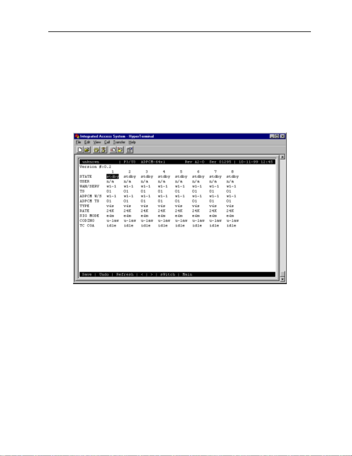
1.3.1 ADPCM Card Main Screen
Y ou must configure the ADPCM card ports for operatio n. This is done from the ADPCM Card
Main Screen, which is shown in Figure 1-1. T o go to this screen, highlight the ADPCM card
in the System Ma in Screen and press <E nter > .
Figure 1-1. Typical ADPCM Card Main Screen
The bottom highlighted line of this screen shows several actions you can perform from the
screen. To perform an action, simply press the key indicated by the uppercase letter of the
desired action. For example, to sa ve your configu ratio n settings , pre ss “s” to invoke the Save
command. Table 1-2 lists these actions.
Server Cards IMACS System Release 5.1.6 1-3
Page 16

Running Head
ADPCM Card User Screens and Settings ADPCM Card
Model No.
Tab le 1-2. ADPCM Card Main Screen Actions
Action Function
Save Saves changes to set tings.
Undo Returns all settings to the last saved state.
Refresh Redraws the current screen with the latest information.
pg_Left Pages through the 64 engines (highest to lowest), 8 at a time.
pg_riGht Pages through the 64 engines (lowe st to highest), 8 at a time.
SWitch Switches an active ADPCM card to its redundant mate.
Main Returns to the ADPCM Card Main Screen . If changes are made to settings
and not saved, users wil l be prompted to save or lose changes.
Table 1-3 summarizes the ADPCM card configuration parameters and available settings.
These are also described in the fol lowing paragraphs.
Table 1-3. ADPCM Card Setting Options and Defaults
Parameter User Optio n s Defa u lt
STATE stdby actv rdnt stdby
USER n/a uX-1 through uX-8 n/a
WAN/SERV n/a w1-1 w1-2 w2-1 w2-2 w3-1 w3-2 w4-1 w4-2 none
TS n/a 01-24 01-31 01
ADPCM W/S w1-1 w1-2 w2-1 w2-2 w3-1 w3-2 w4-1 w4-2 none
ADPCM TS 01-24 01-31 01
TYPE n/a v&s v trnsp v&s
RATE n/a 24K 32K 40K 24K
SIG MODE n/a e&m fxs plar fxo user e&m
CODING n/a u-law a-inv u-law
TC CGA n/a idle busy idle
STATE
The State setting de termines whether the port is active or inactive. When assigning ADPCM
engine pairs for WAN traffic, set the State setting to stdby (standby) for port s that are not yet
used or not yet configured. Set it to actv (active) for ports that are ready for use.
Setting the State to rdnt (r edundant) for any p ort on a n unused card will cause th at card to ac t
as the redundant back-up for all of the other ADPCM cards in that unit. Once a card is
designated as a redundant ADPCM card the only way it can be used for regular ADPCM
traffic is to change the state of the selected port back to either actv or stdby.
When assigning ADPCM e ngine pairs from user cards, changing the port from stdby to actv
and saving the selection information on the user card screen will cause the system to
automatically ass ign an ADPCM engine.
When the engine is assigned from a user card, no changes can be made from the ADPCM card
screen to any of the fields.
1-4 IMACS System Release 5.1.6 Server Cards
Page 17

ADPCM Card ADPCM Card User Screens and Settings
USER
The User setti ng id entifi es the user car d and por t con nect e d to th is eng ine . This is the p lace
where the ADPCM card will expect incoming (non-compressed) voice, subrate data, and
B-channel traf fic. I f assigned fr om a voice, SRU, or BRI card por t, this se lection will s how the
user card slot and port numbe r (e.g., u5-2 for the card in slot U5, port 2). If you are assigning
a WAN time slot, this setting will show n/a.
WAN/SERV
The WAN/SERV setting identifies the incoming WAN link connected to this engine. This is
the place where the ADPCM card will expect incoming (non-compressed) voice. If you are
assigning voice traffic to a WAN time slot, this setting will show w1-1 to w4-2. If you are
assigning to a voice card or SRU card port, this set ting will show n/a.
TS
The Time slot parameter selects the specific time slot of the above WAN link on which the
ADPCM card can expect incoming voice traf f ic. If WAN 1-1 is equipped with a T1 CSU
module or a DSX/CEPT module configured for T1 DSX interface, the options are 1 to 24. If
a DSX/CEPT module is installed on that WAN port and that module is configured for CEPT
E1 interface, the options are 1 to 15 and 17 to 31. If you are assigning time slots to voice or
SRU card ports, this setting will be n/a.
ADPCM W/S
The ADPCM W/S settin g identi fies the o utgoing WAN link to which t he en gine is conne cted.
If you are assigning to a voice, SRU, or BRI card port, or to voice traffic from a WAN time
slot, this setting will show w1-1 through w4-2. This is the WAN link to which the ADPCM
card will send its outgoing (compr essed) traffic.
ADPCM TS
The ADPCM Time slot paramete r selects the spec ific time slot on the WAN link chosen in the
previous settin g that the ADPCM card wil l se nd outgoi ng c ompressed t raf fi c. The opt ions are
determined by the equip ment on the WAN link selecte d in the pre vious setting . If WAN 1-1 is
equipped with an 812 CSU or 81 1 DSX/CEPT Module configured f or DSX, the optio ns are 1
to 24. If a DSX/CEP T module is instal led and configured for CEP T E1, the options are 1 to 15
and 17 to 31.
Server Cards IMACS System Release 5.1.6 1-5
Page 18

Running Head
ADPCM Card User Screens and Settings ADPCM Card
Model No.
TYPE
The Type parameter identifies the voice and signaling requ irements for the incoming circuit.
The options are v (voice), voice and v&s (signa ling) and trnsp (transparent). Use v when the
input to the ADPCM channel is a 64 kbps channel and inband signaling is not required. Use
v&s when the input to the ADPCM channel is a 64 kbps voice channel and the ADPCM card
must also provide inband signaling.
The trnsp setting allows you to map the outputs of SRU ports to the ADPCM channel. The
subrate data will be clocke d into t he ADPCM channel at a n input rate of 24 kbps , then pa ssed
transparently (non-compressed) t hrough the ADPCM card to the appropriate WAN time slot.
This could be useful if you have an odd number of voice channels and want to utilize the
empty engine pair of the last ADPCM channel.
The B-channel traffic from the BRI card also uses the trnsp setting, but it does not place any
restrictions on the compression rates.
If the engine is assigned to a voice card, this selection will show v&s. If assigned to an SRU
card, it will show trnsp. You cannot change it from this screen.
RATE
The Rate parameter identifies the compression requirements for the incom ing circuit. The
options are 24K, 32K, and 40K. The sum of the pair of engines must always equal 64 kbps.
If this engine is assi gned to a user car d port, the sele ction wi ll s how the va lue that wa s chosen
on that port. It cannot be changed from this scre en.
SIG MODE
The Signaling Mode parameter identifies the type of signaling required for the incoming
circuit from the network. If v&s was chosen in the Type setting, the options are e&m, fxs,
plar, and fxo. If v or trnsp was chosen in the Type setti ng, the only option is n/a.
If this engine is assigned to a user card, this selection will show user. It cannot be changed
from this screen.
CODING
The Coding parameter identifies the PCM companding format required for the incoming
circuit from the network. The choices are u-law or a-inv.
If this engine is assig ned to a v oice or BRI car d, this se lection will show the value you selec ted
for that por t. If thi s engine is assigned t o an SRU card, thi s selection will show u-law. It cannot
be changed from this screen.
1-6 IMACS System Release 5.1.6 Server Cards
Page 19

ADPCM Card ADPCM Card Error Messages
TC CGA
The Tru nk Conditioning CGA se tting identif ies the type of trunk condit ioning requi red for the
incoming circuit. If v&s is ch osen in t he Type setting, the opti ons are idle or busy. If trnsp or
v is chosen as the Type, the only option is n/a.
If this engine i s a ssigne d t o a voice card, this sele ction will s how the value you s el ected on the
voice card port. If assigned to an SRU or BRI card port, the field will show n/a. It cannot be
changed from thi s scre en .
1.4 ADPCM Card Error Messages
Refer to Appendix B in the System Reference Guide for further information on Error
Messages regarding this card.
1.5 ADPCM Card Troubleshooting
The following are instructions on how to troubleshoot the ADPCM card. This is in case the
card fails for any reason:
1. Green LED on faceplate.
2. Verify that the card is in the right slot, P1 through P3.
3. Reseat the card if necessary. This can be done with the power on.
4. View the card status on the main sc reen.
5. Check the cards configuration options. Select the card from the main screen to d o this.
6. Now try to log into the ADPCM main screen. If this sti ll didn’t work the card may be
bad. Try swapping it with a new card.
7. If the ADPCM card is determined to be faulty, replace it and return the faulty unit for
repair to the location spe cified by your distributor.
Server Cards IMACS System Release 5.1.6 1-7
Page 20

Running Head
ADPCM Server Card Specifications ADPCM Card
Model No.
1.6 ADPCM Server Card Specifications
ADPCM Card (887160)
Input Voice Channels Can originate from any 2-wire o r 4-wire voice card or from a DSO on a
WAN (El/T1 or HDSL) interface . µ-law & A-law 64Kbps PCM
compatible on a per channel basis.
Input Sub-rate Data SRU data tr affic at 19.2Kbps or less can be carried on a 24Kbp s
sub-channel.
Input BRI traffic B channel voice traffic can be com pressed at any of the configurable
rates.
Modem Data Support Transcoder rate: 24, 32 or 40 Kbps; Modem Data: none, up to 4.8Kbps,
V.32 to 9.6Kbps, up to 12Kbps and V.32 bis to 14.4Kbps
Fax Support Transcoder rate for fax: 24, 32 or 40 Kbps; none, Group I I and Group
III fax.
Voice Quality As measured by Mean Opinion Score (MOS) analysis, a subjective
evaluation with a range of 0 (poor quality) to 5 (good quality). Toll
quality voice is accorded a MOS of 4.0 24Kbps transcoder rate MOS is
3.6-3.8; 32Kbps transcoder rate M O S is 4.0-4.3 and 40Kbps transcoder
rate MOS is 4.0-4.3
Echo Cancellation Non provided—typically not required
Signaling Transmitted in-band utilizing CAS transitional signaling, as per ANSI
T1.302—1986 for 32Kbps and modified for use with 24Kbps and
40Kbps. Note Robbed Bit Signaling A larm Transmission, as specified
in ANSI T1.302a-1989 is not supported.
Maximum Card Count 3 (2 active, 1 redundant)
Transcoder Operation Compliant to G.761 Alarm Indication and Fault Handling.
Standards Compatibility
ANSI T1.302 1989
T1.302a 199 2
T1.303 1989
CEN EN 500 081-1
EN 500-092-1
EN 60950/A2
ITU-T G.721
G.723
G.726 12/90
1-8 IMACS System Release 5.1.6 Server Cards
Page 21

FRS Car d Intro ducti on
Chapter 2
FRS Card
2.1 Introduction
This chapter provides installation, configuration, and troubleshooting information for the
Frame Relay Server (FRS) (881160) card with the 62180 Firmware.
Note that this ca rd is label ed as an ACS card on i ts f aceplate ejector. It is identified as an FRS
card only in the user interface sc reens shown in this chapte r . Throughout the remainde r of this
chapter , it will be referred to as the ACS-FRS card.
2.2 ACS-FRS Card Descriptions
2.2.1 ACS-FRS Card Description (881160)
The ACS-FRS card concentrates multiple N x 56K or N x 64K frame relay da ta streams onto
one or more Nx56/64K links of the Integrated Access System. In addition to frame relay
concentration, the card encapsulates data for Nx56/64K HDLC or SDLC data streams. The
frame relay ser ver sof tware runs o n the card, which provi des up to 68 lo gic al ports. Up to 128
permanent virtual circuits (PVCs) can be configured on a single card. The aggregate speeds
of all ports associated with e ach FRS cannot exceed 8 Mbps.
The maximum frame size supported by the ACS-FRS card is 4,096 bytes p er frame. Each card
can switch 4,000 frames pe r se cond, assum ing a frame siz e of 64 byte s per frame. Up t o three
ACS-FRS cards can be used in a system.
2.2.1.1 Card Jumpers/Switch Settings
The ACS-FRS card does not have any jumpers or switches on its motherboa rd.
2.2.1.2 Installing the Card
Insert the ACS -FR S car d into one o f the serv er card ch as si s slot s (P1 to P3). The sys tem can
accommo dat e up t o three s erv er cards .
Server Cards IMACS System Release 5.1.6 2-1
Page 22
Running Head
ACS-FRS Card User Screens and Settings FRS Card
Model No.
2.3 ACS-FRS Ca rd User Screens and Settings
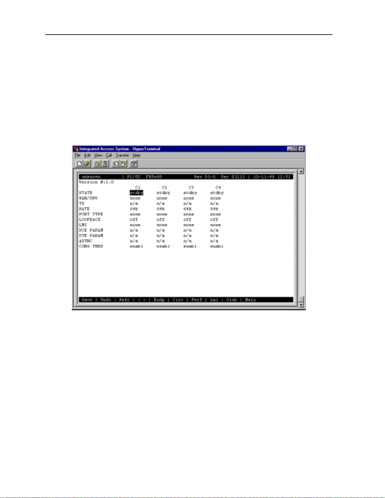
2.3.1 ACS-FRS Card Main Screen
You must configure the ACS-FRS card for opera tion after installing it. This is done in the
ACS-FRS Card Main Screen (Figure 2-1). To go to that screen, highlight the desired
ACS-FRS card in the System Main Screen and press <Enter>.
Figure 2-1.Typical ACS-FRS Card Main Screen (ports C1 to C4)
The 68 logical ports of the card are labeled C1 to C4 and 1 to 64. However , numbered ports 1
to 64 do not appear i n the above display . T o se e those por ts, press th e "<" and ">" keys to scrol l
through them, eight a t a time. Figure 2-2 shows a n ACS-FRS card Main Scr een display for the
first eight numbered port s.
The ports C1 to C4 cannot be used for Nx56k, only port 1 to 64 can.
Both the IPR (883060/883160) and the PM-IOR (828060) cards be used with the ACS-FRS
card. The PM-IOR card however, is limit ed to only 14 PVCs per card, wher eas the maximum
number of PVCs available on the IPR card is 128.
When connecting the ACS-FRS card to the IPR or the PM-IOR, one of the 64 ports available
will be used for the communication betwe en the two.
2-2 IMACS System Release 5.1.6 Server Cards
Page 23
FRS Card ACS-FRS Card User Screens and Settings
The maximum bandwidth possible between the IPR and ACS-FRS cards is 62 time slots
provided on the internal buses “ A” and “B.”
The “C1” and “ C2” por ts o f the F RS ca rd cann ot toge ther be assig ned more t han 32 time slots
due to hardware l imitations. The same is true for the FRS ports “C3” and “C4”. A total of 64
time slots can be assigned all the “C” ports. A similar limitation exists for the ports 1-64
terminating the voice ci rcuits. Each group of 32 ports, 1-32, and 32-64 share a common
internal pipe limite d to 32 time slots each. The maximum number of time slots allows pe r port
is one when all por ts per gr oup is active . If ha lf th e number of ports of a group i s a ctive, twi ce
the number of time slots can be assigned per port.
The maximum internal bandwidth between FRS cards and HSU cards of an Integrated Access
System is limited by the pools size of 126, but also limited by usage from this pool by the
IPR/FRS connections and possible voice card usage.
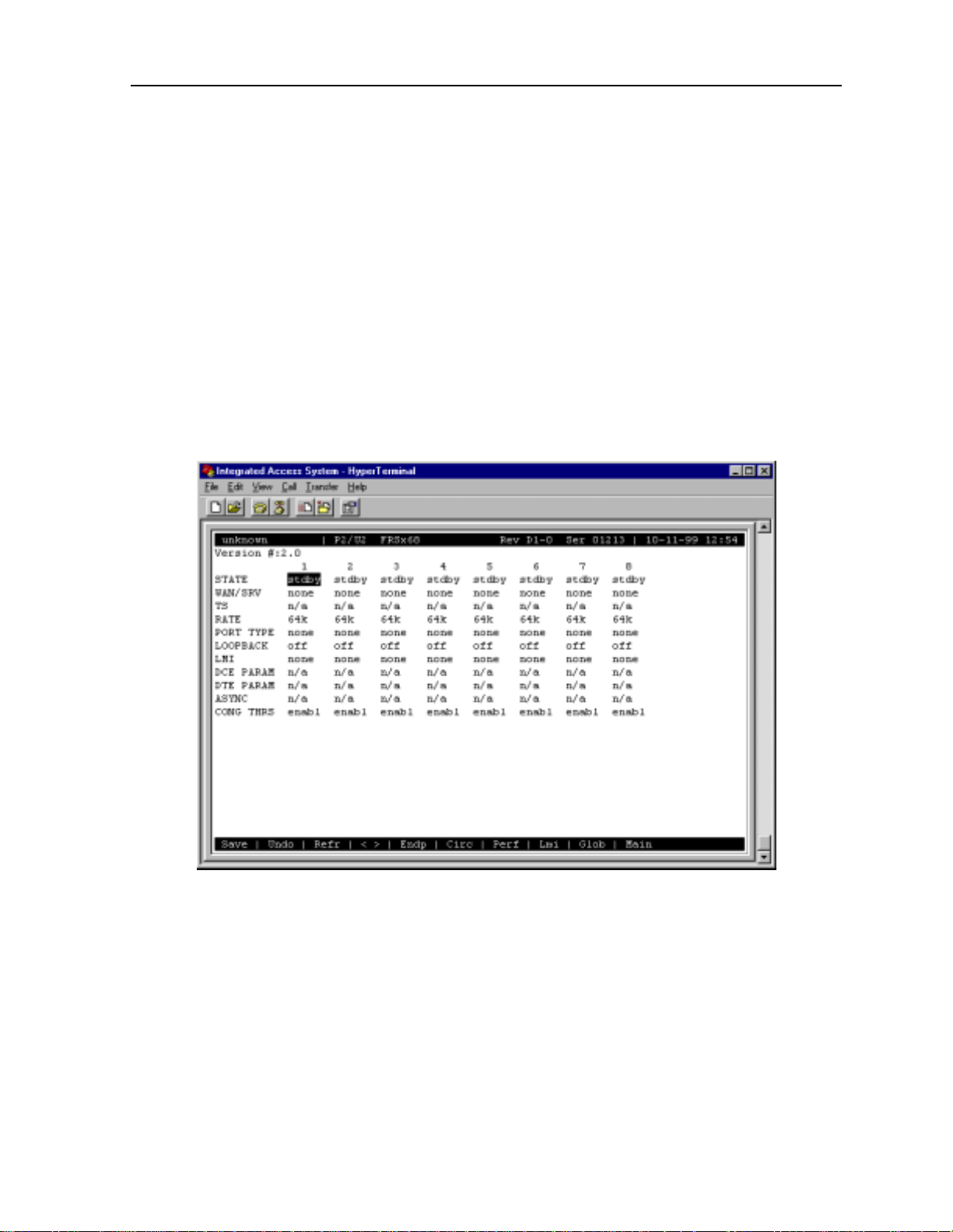
Figure 2-2.Typical ACS-FRS Card Main Scree n (numbered ports)
T able 2-1 lists the actions you can perform from the ACS-FRS Card Main Scre en. These
actions are liste d at the bottom line of the screen; they are pe rformed by pressing the uppercase
letter key. For example, to save your option settings, pre ss “s” to invoke the Save command .
T able 2-2 summarizes the parameters and their option settings and defaults.
Server Cards IMACS System Release 5.1.6 2-3
Page 24

Running Head
ACS-FRS Card User Screens and Settings FRS Card
Model No.
Table 2-1. ACS-FRS Card Main Screen Actions
Action Function
Save Saves changes to settings.
Undo Returns all settings to the last saved state.
Refresh Re dr aws the scree n.
< and > Lets you scroll through the 68 logical ports assignable on each ACS-FRS
card.
Endp Brings up the PVC Endpoi nts Screen where endpoints for each PVC are
assigned. See the PVC Endpoints Screen section of this chapter.
Circ Brings up the Circ uits Screen where alternate endpoints and endpoint
switching are ass i gned. See the Circuits section of this chapte r.
Perf Initiates Port Performance Monitoring of the selected ACS-F RS card port.
Refer to Port Performance Data section of this chapter.
Lmi Brings up the LMI Screen where additional performance s tatistics are
stored. See the LMI section of this chapter.
Glob Brings up the Global Screen that identifies the ACS-FRS card by IP number
and netmask. See the Global Setup section of this chapter.
Main Returns to the S ystem Main Screen. If changes are made to settings and n ot
saved, you will be prompted to save or lose changes.
Table 2-2. ACS-FRS Card Main Screen Option Settings and Defaults
Parameter User Options Notes Default
STATE stdby actv stdby
W AN/SRV none w1-1 w1-2 w2-1 w2-2 w3-1
w3-2 w4-1 w4-2
TS n/a table n/a
RA TE 64k 64
PORT TYPE none u-dce nni u-dte frad n one
LOOPBACK off line local off
LMI none ansi ccitt lmi 1 none
DCE PARAM n/a enabl 2 n/a
DTE PARAM n/a enabl 3 n/a
ASYNC no yes no
CONG THRS enabl 1%-100% 4 e nabl (95%)
Notes:
1. ansi, ccitt, and lmi can only be selected when Port Type is changed to any selection
other than none.
2. When Port T ype is u-dce or nni, th is paramete r will let you c hange the Error Thr eshold,
Poll Verify Timer, and Events Counter settings.
none
3. When Port Type is u-dte or nni, this paramet er will let you change the Error Thre shold,
Poll Interval Timer, Events Counter, and Full Status Frequency.
4. Press <Enter> to select the desired Congestion Threshold percentages.
5. If connected to a user port, this displays user slot number and port (e.g. U1-2).
2-4 IMACS System Release 5.1.6 Server Cards
Page 25

FRS Card ACS-FRS Card User Screens and Settings
STATE
The State setti ng determ ines whe ther the port i s acti ve or inac tive. Set the Sta te fie ld to stdby
(standby) for por ts you are not using or have not yet configured. Or, set it to actv (active) for
ports that are ready for use.
WAN/SRV
The WAN setting identifies the WAN link assigne d to this port. You do not have to a ssign all
ports on the same card to the same WAN link. You also don’t have to assign card ports to
contiguous time slots of a WAN link. The default value is none.
TS
The Time Slot setting identifies the time slots on the WAN link when wan is selected in the
previous setting. The ACS-FRS card can use many (up to 24 T1 or 31 E1) time slots on a
single WAN port, in order to create a super-ra te circuit for an individual FRS port. One or all
time slots of a T1 or E1 lin k can be a ssembled for use by the FRS po rt, ac cording to th e s peed
requirements of the DTE.
You can assign time slots by pressing <Enter> and using the space bar to select and deselect
the required number of time slots. These assignments do not have to be contiguous.
RATE
The Rate setting allows you to adjust the speed of the ci rcuit according to the application
requirements. The only speed availab le for ports C1to C4 is 64k (64 kbps). Howe ver, ports 1
to 64 can be set to either 56k or 64k.
PORT TYPE
The Port Type identifie s the type of interface expecte d for this port. The selections are none,
u-dce (User-to Network Interface), nni (Netw o rk to N et wo rk Inter fac e), u-dte (User-to
Terminal Equipment), and frad (Fram e Relay A sse mb ler/Dissemb le r).
LMI
The Local Management Interface setting allows you to select the protocol to be used by this
port. The options are none, ansi (ANSI T1.617 Annex D), ccitt (ITU Q.933 Annex A), and
lmi (Group of Four specification).
Server Cards IMACS System Release 5.1.6 2-5
Page 26

Running Head
ACS-FRS Card User Screens and Settings FRS Card
Model No.
DCE PARAM
The DCE Parameters setting will show n/a unless a Port T ype of u-dce or nni is selected. Once
set to enable, the user may choose from the following options:
• Error Threshold (N392)
• Poll Verify Timer (T391)
• Events Counter (N393)
The Error Threshold (N392) counts the err ors that will be toler ated during the cast number of
events as set by t he Events Counter b efore declaring th e LMI link down. The number of error s
options are 1 to 10. The value is input using the keyboard of the contr ol terminal. The default
is 3.
The Poll Verify Timer (T391) allows you to select the time interval (in seconds) that should
elapse between “keep alive” messages sent from the corresponding DTE. The number of
seconds options are 5 to 30. The default is 15 seconds.
The Events Counter (N393) allows you to sele ct the window size for the number of events
(frames) in which errors will be counted. If error threshold (N392) is exceeded within cast
N393 frames, th e link is declared down. The number of events count ed are 1 to 10. The default
is 4.
DTE PARAM
The DTE Parameters setting will show n/a unless a Port T ype of u-dte or nni is selected. Once
set to enable, the user may choose from the following options:
• Error Threshold (N392)
• Poll Interval Ti mer (T391)
• Events Counter (N393)
• Full Status Frequency (N391)
The Error Threshold (N392) counts the err ors that will be toler ated during the cast number of
events as set by t he Events Counter b efore declaring th e LMI link down. The number of error s
options are 1 to 10. The value is input using the keyboard of the contr ol terminal. The default
is 3.
The Poll Verify Timer (T391) allows you to select the time interval (in seconds) that should
elapse between “keep alive” messages sent from the corresponding DCE. The number of
seconds options are 5 to 30. The default is 15 seconds.
2-6 IMACS System Release 5.1.6 Server Cards
Page 27

FRS Card ACS-FRS Card User Screens and Settings
The Events Counter (N393) allows you to sele ct the window size for the number of events
(frames) in which errors will be counted. If error threshold (N392) is exceeded within cast
N393 frames, th e link is declared down. The number of events count ed are 1 to 10. The default
is 4.
The Full Status Frequency (N391) allows you to sel ect the number of “keep alive” messages
(see T391 above) that sh ould elapse befor e the full statu s inquiry mes sage is sent. The number
of messages are 1 to 255. The default is 6.
ASYNC
This setting specifies whether a synchronous state's update messages are to be sent when
changes on the link occur. If set to no, link upd ates ar e sent at regular int erva ls, in r esponse to
Full Status Reques ts.
CONG THRS
The Congestion Thresho ld allows you to select t he amount (in perc entage) that the interna l Tx
queues on the port must be filled before declaring this port is congested (this info rmation is
communicated by FECN and BECN flags). The options are 1 to 100.The default is 95.
Since DE (Discard-Eligibility) frames are not queued to the same extent as non-DE frames,
DE-frames may be dropped when mixed with non-DE frames on the same port before
congestion control is initiated.
T o assure congestion control is initiated even for DE-frames under the conditions mentioned
above, the TX threshold value must be reduced sufficiently to match the percent age
DE-frames being buffe red.
Server Cards IMACS System Release 5.1.6 2-7
Page 28
Running Head
ACS-FRS Card User Screens and Settings FRS Card
Model No.
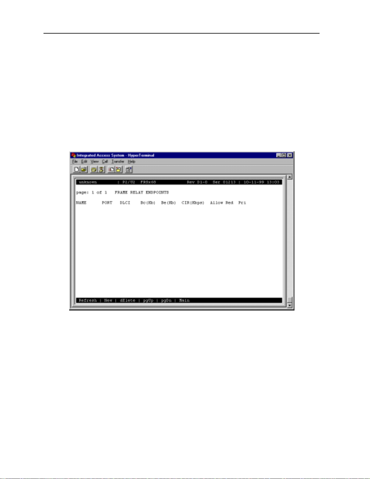
2.3.2 Frame Relay Endpoints Screen
You can have up to four frame relay endpoints (two for the actual endpoints of the PVC and
two that can act as backup should the primary link fail). All frame relay endpoints are
inventoried on the Frame Rel ay Endpoints Screen, and a ll endpoint s must be defined from this
screen before the user can provision the circuit.
Figure 2-3 shows a typic al Frame Relay Endpoints Screen, which can be viewed by pressing
“e” (Endp) in the ACS-FRS Card Main Screen. T able 2-3 lists the actions you can perform
from the bottom line of this screen.
Figure 2-3.Ty pical Frame Relay Endpoin t s Screen
In Figure 2-3 above illustrates the frame relay endpoint screen for two voice circuits
terminated on port 01, and 02 transported over port “C1” via the HSU to the remote device.
Figure 2-3 also shows the thre e IP endpoints define d on C1 towards the remote device, and on
C2 towards the IPR .
2-8 IMACS System Release 5.1.6 Server Cards
Page 29

FRS Card ACS-FRS Card User Screens and Settings
Ta bl e 2-3. Frame Relay Endpoints Screen Actions
Action Function
Refresh Re dr aws the scree n.
New Adds new circuit endpoints for each of the Frame Relay ports
dElete Deletes the highlighte d endpoints. The system requires confirmation with a
yes/no question before deleting the circuit.
pgUp Pages through the pages of Frame Relay endpoints from newest to oldest.
pgDn Pages through the pages of Frame Relay endpoints from oldest to newest.
Main Returns to the S ystem Main Screen. If changes are made to settings and n ot
NAME
The Name setting allows you to identify each of the endpoints with a discrete name. This
setting is case-sen sitive, so a endpoint called “P101” is not the same as one called “p101.”
Circuits are built usi ng these names.
saved, you will be prompted to save or lose changes.
PORT
The Port number identifies the Frame Relay port used for this circuit. This inform ation is input
by the user from the keyboard. Valid entries are C1 to C4 and 1 to 64.
DLCI
The Data Link Connection Identifie r is a unique number assigned by the carrier to this
endpoint. The number must be betwe en 1 and 996 (ansi or ccitt), or 1 and 1007 (lmi). The othe r
numbers within the 1023 range are reserved.
BC(Kb)
The Bits Committed setting defines the threshold for the transmit rate (outgoing frames)
where the card will make every effort to deliver the traffic to the subscriber. The time used to
average rate is determined by the card by dividing the Committ ed Information Rate (CIR) by
Bc. The number input must be between 0 and 2048.
BE(Kb)
The Bits Excessive setting defi nes the threshold for the transmit rate (outgoing frames) where
the carrier will admit the frames into the network (in effect, this is the maximum transmission
rate). Frames sent below this threshold but above the BC (KB) threshold are admitted into the
carrier network with the DE (discard eligibility) bit set. If congestion occurs in the network,
these frames are the first to be discarded. The options are 0 to 2048.
Server Cards IMACS System Release 5.1.6 2-9
Page 30

Running Head
ACS-FRS Card User Screens and Settings FRS Card
Model No.
CIR (Kbps)
The Committed Information Rate (in kbps) is the actual information rate contracted with the
carrier. The options are 0 to 2048. CIR/Bc is used to calculate average data rate.
When CIR is set to 0, all frames forwarded will have the DE-bit set.
ALLOW RED
When Allow Red is set to yes transmit rate exceeding BC+Be will be forwarded if there is
capacity avai lab l e. When s et to no forwarding will not be attempted.
PRI
The Priority field all ows selection of prio rity 1-4. Thi s field is only available f or the ACS-F RS
(881163) card. Default setting is priority “4”. When the user has installed ACS-FRS (8811)
card the priority fiel d will not be able to be edited and will show n/a.
2-10 IMACS System Release 5.1.6 Server Cards
Page 31

FRS Card ACS-FRS Card User Screens and Settings
2.3.3 FRS Circuits Screen
The FRS Circu it s Sc reen al l ow s you to iden tify PV C en dpo in t s and alter n at e PVCs to s erve
as backups to the origina l endpoints if the main link fails. Endpoin ts must be inventoried on
the PVC Endpoints Screen before they can be used to set up backup circuits. Figure 2-4
shows a typical Ci rcuits Scr een, a nd Figure 2-5 i s an endpoint cir cuit e xample. Table 2-4 lists
the actions you can perform from the bottom of this screen.
Figure 2-4.Typical Circuits Screen
Currently the FRS is li mited to 128 circ uit s connecti ng 256 endpoint s. The Inte grated Ac cess
System is requi re d to serve a maxi m u m of 8 EBT S u nits , each h av ing a tot al of 16 chan n els .
Each EBTS can be address by three different IP addresses. Each IP address represents a
specific type of ser vice. Ea ch of the serv ices: signa lin g, messing, and NMS will be address ed
EBTS by a different IP address. The IP router card will encapsulate IP Datagrams for each
service with a unique DLCI value. The IP frames are self-contained in that channel
information is embedded in the dat a of the data gram.
The total of 152 circuits will be required for both voice and IP circuits. Even though the
maximum number of circuits for a single FRS card coul d be expanded to acc ommodate the
needed number . When using two FRS cards, 64 circu its per card can be used as IP circuits after
64 circuits have been used as voice circuits.
Server Cards IMACS System Release 5.1.6 2-11
Page 32

Running Head
ACS-FRS Card User Screens and Settings FRS Card
Model No.
Table 2-4. FRS Circuits Screen Actions
Action Function
Refresh Re dr aws the scree n.
New Creates new circuit.
dEl Deletes the highl ighte d circu it. You will be prompted with a yes/ no qu estion
prior to actual deletion of the circuits.
pgUp Pages up through the circuits.
pgDn Pages down through the circuits.
Perf Brings up circuit performance data f or the highlighted circuit . See the
Status Shows circuit status, as described above.
swA Used for manually swit chi ng from primary endpoint A to al te rnate endpoint
swB Used for manually swi tching from primary endpoint B to alternate endpoint
Main Return s to the FRS Card Main Screen. If changes are made to settings and
Circuit Performance Data section of thi s chapt er.
A, and back.
B, and ba ck.
not saved, you will be prompted to save or lose changes.
End Points
BRI
HSU
0/35
53
0
6
S
O
X
F
9
813
CPU
CLOCK
NVRAM
WAN
IF
1
S
+D
T1
P
1
N
O
D
E
T
P
E
2
R
M
C
O
M
P
P
3
-1
1
W
SU
C
W1-2
P
4
X
S
D
IAD #1
HSU-T
5
530/3
0
6
S
HSU-T
/35
530
60
S
T
U
S
H
35
/
0
53
0
S 6
-T
U
S
H
5
3
/
530
0
6
S
U-T
S
H
5
3
/
530
0
6
S
HSU-T
5
3
/
30
5
60
S
P
1
.
nc
I
tions,
a
unic
m
m
0
o
C
60
S/
C
A
misys
e
M
Pr
del I
o
M
A
5
T
V
250
EC
I
®
e
us
F
3
6
A SB
0
5
V
~
0
LR 77
4
V
0
-2
5
0
2
0
C
-2
0
2
1
-
ued
/CSA
L
z
n
U
O
+
-
/ 60 H
0
r conti
+
o
5
,
M
F
-
3A
V
B
+
,
R
P
V
fire
A
st
n
G
CAUTION:
V
e
gai
N
a
n
sam
o
1
R
e
h
t
ecti
t
h
t
pro
y wi
l
on
ace
l
rep
5A
ing of fuse
at
U
r
8V
and
4
L
e
24/
yp
®
urce
t
So
ower
P
9
K0
9
ss 2
a
Cl
STED
I
L
Telephone
ent
m
p
i
u
Eq
Frame Relay
Network
NY Prm
NY Alt
T
US
H
/35
0
3
5
0
6
S
T
U
S
H
35
/
0
3
5
60
S
I
R
B
U
S
H
35
/
0
3
5
0
6
S
O
FX
9
3
1
8
U
P
C
K
C
CLO
M
A
R
V
N
N
WA
F
I
+DS1
T1
P
1
P
1
N
O
D
E
T
P
E
2
R
M
C
O
P
M
P
1
P
3
W1-1
U
CS
2
W1
P
4
DSX
IAD #2
LA Prm
-T
HSU
5
3
/
0
3
5
60
S
T
U
HS
5
3
/
0
53
0
6
S
T
HSU5
530/3
0
6
S
T
U
HS
/35
0
3
5
0
6
S
Inc.
ions,
cat
i
n
0
0
Commu
ys
ACS/6
mis
e
M
I
l
Pr
ode
M
5A
T
V
0
25
EC
I
®
e
s
Fu
B
S
3
6
A
5
70
7
V
R
~
0
L
4
V
0
-2
5
0
2
C
-20
0
2
1
ed
-
u
z
n
UL/CSA
O
H
+
onti
-
60
/
0
+
5
,
M
For c
-
3A
V
B
+
,
R
V
A
st fire
n
i
G
CAUTION:
V
N
aga
same
on
i
R
e
ect
t
th th
ro
i
p
nly w
o
se
e
u
of f
g
replac
5A
in
at
U
r
nd
a
48V
L
ce
24/
ype
®
ur
t
o
S
Power
ss 2
a
D 9K09
l
C
TE
IS
L
e
n
o
h
p
e
l
Te
t
n
pme
ui
Eq
LA Alt
Router
Figure 2-5.Typical FRS Endpoint Circuit
STATE
The State setting shows the status of the circuit. The options are stdby and actv. This setting
shows the administrative state of the circui t. The operationa l state of each of the endpoi nts of
the circuit is shown in the STATUS column.
ENDP A
Endpoint A is the F RS port used to provide service to the primary end of the PVC. All of the
endpoint names assigned on the PVC Endpoints Scr een (d iscussed earlier) are eligibl e
options.
2-12 IMACS System Release 5.1.6 Server Cards
Page 33

FRS Card ACS-FRS Card User Screens and Settings
ENDP B
Endpoint B is the FRS port used to provide service to the seconda ry end of the PVC. All of
the endpoint names assigned on the PVC Endpoints Screen (discussed earlier) are eligible
options.
ALT A
Alternate En dpoint A is the F RS port u sed to provid e backup se rvice to the primar y end of t he
PVC. All of the en dpoint names a ssigned on the P VC Endpoints Screen ( discusse d earlier) a re
eligible options.
ALT B
Alternate Endpoi nt B is the FRS port used to provide backup service to the se condary end of
the PVC. All of the endpoint names assigned on the Endpoint sc reen (discussed earlier) are
eligible options.
SWCH A
The Switch A setting identifies the method used to switch from the primary Endpoint A to the
Alternate Endpoi nt A. The options are manual and w/to (with time-out). I f w/to is chosen, a
second setting appears f or the use r to select the time-out period (in minutes) from 1 to 60.
In the event of a failure of the primary endpoint, a setting of manual allows the user to
manually switch from primary to the alternate endpoint. When the primary endpoint is
restored, the user must manually switch it back again.
In the event of a failure of the primary endpoint, a setting of w/to will automatically switch
the PVC from primary to alternate. When the primar y endpoint is restored, the system will
automatica lly swi tch it back aga in after the predetermi n ed time set by the user.
SWCH B
The Switch B setti ng identi fi es the meth od use d to swit ch from the pr imary End point B to the
Alternate Endpoint B. The options are manual (pressin g “b” from the bottom line of the
screen), and w/to (with time-out). If w/to is chosen, a second settin g appears for the user to
select the time- out pe rio d (in mi nut es) fro m 1 to 60.
In the event of a failure of the primary endpoint, a setting of manual allows the user to
manually switch from primary to the alternate endpoint if he chooses. When the primary
endpoint is restored, the user must manually switch it back again.
Server Cards IMACS System Release 5.1.6 2-13
Page 34

Running Head
ACS-FRS Card User Screens and Settings FRS Card
In the event of a failure of the primary endpoint, a setting of w/to will automatically switch
the PVC from primary to alternate. When the primar y endpoint is restored, the system will
automatica lly swi tch it back aga in after the predetermi n ed time set by the user.
Model No.
STATUS
The Status column sho ws the sta tus of the Primar y and Alter nate endpoint s and the connection
of the PVC. You cannot edit this field. The val ues are “A” (Primary A is active), “B” (Primary
B is active), “U” (the conne ction i s up), “ a” (Alte rnate A is active), “b” (Alternate B is active)
and “D” (connection is down). Only displays status when “S” (Status) is selected from the
bottom of the screen.
2-14 IMACS System Release 5.1.6 Server Cards
Page 35

FRS Card ACS-FRS Card User Screens and Settings
2.3. 4 FRS Circu it Perfo rmance Data Screen
The ACS-FR S card accumulat es stat is tic s tha t sh ow perf ormance charact eris tic s of each
circuit. To access the FRS Circuit Performance Data Screen, highlight one of the circui ts on
the FRS Circuits Screen and press “p” (Perf). Figure 2-6 shows a typical FRS Circuit
Performance Data Scr een, and T a ble 2-5 lists th e actions you can perform fr om its bottom line .
The circuit perform ance data is kept i n 15-minute (900 sec onds) t ime increment s for a total of
96 periods (24 hours). Each screen shows the current 15 minute segment and the past 12
periods with totals at the bottom of the column. Press “d” to page backward through the
previous 96 periods, or “u” to page forward through the se periods. After each period, the
oldest 15-minute segment (from exactly 24 hours ago) is discarded. Since information is not
updated on screen in real time, you must press “r” (Refresh) periodically to obtain up- to-date
statistics for the curr ent period.
Figure 2-6.Typical Circuit Performance Data Screen
Server Cards IMACS System Release 5.1.6 2-15
Page 36

Running Head
ACS-FRS Card User Screens and Settings FRS Card
Model No.
Table 2-5. Circuit Performance Data Screen Actions
Action Function
Refresh Since performance st atistics are not updated on screen in “real” time, the
refresh key must be presse d to obtain updated performance fig ures.
Clear Clears all performance statistics for the highl ighted port.
PgUp Pages up through the 96 time s egments.
PgDn Pages down through the 96 time segments.
ConG Brings up the Circuit Congestion Data Screen. See the Circuit Congestion
Data sect ion of this chapter.
Main Return s to th e Ci r cu i ts Screen .
AB FRAMES
The AB FRAMES counter sh ows the tota l number of frames sent from endpoint A to endpoin t
B.
BA FRAMES
The BA FRAMES counter shows t he total n umber of frames s ent from endpoin t B to endpoi nt
A during the time period.
AB BYTES
The AB BYTES counter shows the total number of bytes sent from endpoin t A to endpoint B
during the time period.
BA BYTES
The BA BYTES counter shows the total number of bytes sent from endpoin t B to endpoint A
during the time period.
AB DRP
The AB DRP counter shows t he tot al num ber o f frames d rop ped that were se nt from endpoin t
A to endpoint B during the time period.
BA DRP
The BA DRP counter shows t he tot al num ber o f frames d rop ped that were se nt from endpoin t
B to endpoint A during the time period.
2-16 IMACS System Release 5.1.6 Server Cards
Page 37

FRS Card ACS-FRS Card User Screens and Settings
STATUS
The Status column shows the status of the selected circuit during the 15-minute intervals. The
Status values are A or a (capital A means endpoint A was switched from alte rnate to primary
and lower-cas e a means the endpoint A was switched from primary to alternate); B or b
(capital B means endpoint B was switched from alterna te to primary, lower-case b means
endpoint B was switched from primary to alternate); D (connection was down during that
period); and S (circuit was placed in standby state during that period).
Server Cards IMACS System Release 5.1.6 2-17
Page 38

Running Head
ACS-FRS Card User Screens and Settings FRS Card
Model No.
2.3.5 Circuit Congestion Data Screen
The ACS-FRS card also accumula tes statistic s that show you the co ngestion char acteristics o f
each of the circuits. To access the Circuit Congestion Data Screen, press “g” (conG) in the
FRS Circuit Performance Data Scree n. F igure 2-7 shows a typical Circuit Congestion Data
Screen, and Table 2-6 lists the actions you can perform from its bottom line.
The data on this screen is kept in 15-minute (900 seconds) time increments for a total of 96
periods (24 hours). Each screen shows the current 15 minute segment and the twelve past
periods with totals at the bottom of the colu mn. Press “d” (pgDn) to scroll backward through
the previous 96 periods, or “u” (pgUp) to scroll forward through these periods. After each
period, the old es t 15-m inu t e seg me nt (fro m exa ct ly 24 hours ago) is discarded. Since
information is not update d on screen in rea l time, you must press “r” (Refresh) periodically
to obtain up-to-date statistics for the current period.
Figure 2-7. Typical Circuit Congestion Data Screen
2-18 IMACS System Release 5.1.6 Server Cards
Page 39

FRS Card ACS-FRS Card User Screens and Settings
Table 2-6. Circuit Congestion Data Screen Actions
Action Function
Refresh Since performance st atistics are not update d on screen, you must press “r”
to obtain updat ed performance figures.
pgUp Pages up through the 96 time segments.
pgDn Pages down through the 96 time segments .
A->b Selects th e direction of the congest ion data.
B->a Selects the direction of the congestion data.
Main Returns to the Circuit Performance Data Screen.
GREEN FR
The Green Frames cou nter shows the to tal number of fr ames sent on t he circuit tha t fell within
the Committed Information rate contracted with the carrier during the time period.
DROP
The first DROP shows the number of Green Fra mes that were dr opped by the card durin g the
time period.
YEL FR
This counter shows the total number of frames on the cir cuit that exceeded the Bc rate but were
within the Be rate assigned to the endpoi nt during the time period.
DROP
The second DROP shows the number of Yellow Frames that were dr opped by th e card during
the time period.
RED FR
This counter shows the total number of frames on the cir cuit that exceeded the Be rate
assigned to the endpoint during the time period.
DROP
The third DROP shows the number of Red Frames that were dropped by the card during the
time period.
Server Cards IMACS System Release 5.1.6 2-19
Page 40

Running Head
ACS-FRS Card User Screens and Settings FRS Card
Model No.
FECN
The Forward Error Congestion Noti ficati on counter l ogs the numb er of frames wi th the FECN
bit set by the system. This flag tells you that congestion avoidance procedures should be
initiated.
BECN
The Backward Error Congestion Notif ication counter logs the number of frames with the
BECN bit set by the sys tem. This flag tells you tha t congestion avoidance proc edures should
be initiated.
2-20 IMACS System Release 5.1.6 Server Cards
Page 41

FRS Card ACS-FRS Card User Screens and Settings
2.3.6 Port Performance Data Screen
The ACS-FRS card also accumulates stati stic s that show you th e performanc e characte risti cs
of each acti ve port. To address the Port P erformance Dat a Screen, high light one of the 68 po rts
on the ACS-FRS Card Main Screen and press “p” (Perf). This will access the Port
Performan ce Da ta Screen associated w ith the sel ect ed p ort . Figure 2-8 shows a typical Po rt
Performance Data Scr een, and T a ble 2-7 lists th e actions you can perform fr om its bottom line .
The data on this screen is kept by 15-minute (900 seconds) time increments for a total of 96
periods (24 hours). Each scr een shows the curre nt 15 minute segment and the past 12 periods
with totals at the bottom of the column. Press “d” (pgDn) to page backward through the
previous 96 perio ds, or “u” (pgUp) to page forward through t hes e periods . After ea ch perio d,
the oldest 15-minute segment (from exactly 24 hours ago) is discarded. Since information is
not updated on screen in real time, you must press “r” (Refresh) periodically to obtain
up-to-dat e stati stics fo r the current period.
Figure 2-8. T ypical Port Performance Data Screen
Server Cards IMACS System Release 5.1.6 2-21
Page 42

Running Head
ACS-FRS Card User Screens and Settings FRS Card
Model No.
Table 2-7. Port Performance Data Screen Actions
Action Function
Refresh Since performance st atistics are not updated on screen in “real” time, the
refresh key must be presse d to obtain updated performance fig ures.
Clear Clears all performance data for the highlighted port.
pgUp Scrolls up through the 96 time segments.
pgDn Scrolls down through the 96 time segments.
Main Returns to the System Main Screen.
PORT
The Port setting shows the port number ass ociated with the performance statistics on this
screen. This was the port highlighted on the Main screen when the “ P” key was pressed. The
FRS card has a maximum of 68 ports.
FRAME Rx
The Frame Received column tabulates the total number of frames received during the 15
minute period.
FRAME Tx
The Frame T ransmitted col umn tabulates the total number of frames transm itted during the 15
minute period.
OCTETS Rx
The Octets Received column tabulates the total number of bytes received during the 15 minute
period.
OCTETS Tx
The Octets Transmitted column t abul ates the total number of bytes transmitted during the 15
minute period.
DRPRx
The Dropped (frame) Received column tabulate s the total number of frames dropped on port
while being received.
2-22 IMACS System Release 5.1.6 Server Cards
Page 43

FRS Card ACS-FRS Card User Screens and Settings
DRPTx
The Dropped (frame) T ransmitted col umn tabulates the total num ber of frames dropped bef ore
being transmitted duri ng the 15 minute period.
STATUS
The Status co lumn shows diff erent stat us conditions of the port during eac h 15-minute perio d.
The status codes are listed at the bottom of the screen. The status codes are T (DTE down), C
(DCE down), L (loopback), and S (standby).
2.3.7 LMI Data Screen
Local Management Interfa ce inf ormation is dis played on the LMI Dat a Scre en. To access this
screen, press “ L” in the AC S-FRS Ca rd Main Scre en t o i nvoke the Lmi command. Figur e 2 -9
shows a typical LMI Data Screen, and Table 2-8 lists the actions you can perform from the
bottom line of this screen.
Figure 2-9.Typical LMI Data Screen
Server Cards IMACS System Release 5.1.6 2-23
Page 44

Running Head
ACS-FRS Card User Screens and Settings FRS Card
Model No.
Table 2-8. LMI Data Screen Actions
Action Function
Refresh Save s chan ges to settin gs.
Clear Returns all settings to the last saved state.
Main Returns to the System Main Screen.
STATUS INQ. RX
The Status Inquiry Rec eived figure shows the total number of status inquiry req uests received
by the DCE.
STATUS TX
The Status Transmitted fig ure sh ows the tot al number of “keep a live” a nd full s tatus i nquir ies
sent by the DCE.
ASYNC STATUS TX
If the ASYNC parameter in the ACS-FRS card Main Screen is set to yes for the port,
asynchronous status packets transmitted by the DCE are tabulated in this figure.
SEQ # MISMATCH
The Sequence Number Mismatch figure shows the tota l number of sequence number errors
have been received by the DCE.
TIMEOUTS
The Timeouts f igure shows the total num ber of times that expect ed requests fro m the DTE are
missed.
BAD HDLC FRAMES
The Bad HDLC Frames figure shows the total number of HDLC errors received on this port.
INVALID FRAMES
The Invalid Frames figure shows the tota l number of short frames or frames with invalid FR
headers received on this port.
2-24 IMACS System Release 5.1.6 Server Cards
Page 45

FRS Card ACS-FRS Card User Screens and Settings
NO ROUTE FRAMES
The No Route Fra mes figu re s hows the total number of fr ames re ceived that ha ve i ncorre ct or
unknown DLCI for this port.
STATUS INQ. TX
The Status Inquiry Transmit figure shows the total number of status inquiry requests
transmitted by the DTE.
STATUS RX
The Status Rece ive d figu re sho ws the total number of “keep al i ve” an d full stat us inqu i ries
rece ived by the DTE.
ASYNC STATUS RX
If the ASYNC parameter in the ACS-FRS card Main Screen is set to yes for the port,
asynchronous status packets received by the DTE are tabulated in this figure.
SEQ # MISMATCH
The Sequence Number Mismatch figure shows the tota l number of sequence number errors
have been received by the DTE.
TIMEOUTS
The Timeouts f igure shows the total num ber of times that expect ed requests fro m the DTE are
missed.
Server Cards IMACS System Release 5.1.6 2-25
Page 46

Running Head
ACS-FRS Card User Screens and Settings FRS Card
Model No.
2.3.8 Global Setup Screen
The Global Data Screen allows you to identif y the frame relay server by its IP address. To
access this screen, press “g” in the ACS- FRS Card Main Scr een to inv oke the Glob command .
Figure 2-10 shows the Global Data Scree n, a nd Table 2-9 lists the available actions from the
bottom line of this screen.
Figure 2-10. Global Data Screen
Table 2-9. Global Data Screen Actions
Action Function
Save Saves changes to settings.
Undo Returns all settings to the last saved state.
Refresh Re dr aws the scree n.
Main Returns to the S ystem Main Screen. If changes are made to settings and n ot
saved, you will be prompted to save or lose changes.
IP ADDRESS
Enter the IP address for the frame relay server in this field.
2-26 IMACS System Release 5.1.6 Server Cards
Page 47

FRS Card ACS-FRS Card Error Messages
NETMASK
Enter the Netmask addr ess in this field. This is the Netmask fo r the Integrated Acc ess System.
This address is also assigne d on the Interf ace card’s IP Screen.
2.4 ACS-FRS Ca rd Error Messages
Refer to Appendix B in the System Reference Guide for further information on Error
Messages regarding this card.
2.5 ACS-FRS Card Troubleshooting
Problems with a FRS card could indicate a number of causes. Some possibilities are:
• T1 or E1 network failure
• Improper frame relay network configuration
• Improper FRS card configuration
• Improper user card configuration
• Faulty cabling between the DTE and user card
• Improper DTE configuration
T ypically, a problem is indicated by the inability to send or receive frame relay traf fic through
the FRS card. There are numerous ways of isolating and clearing the problem. When
troubleshooting frame relay communications problems through an FRS card, follow this
general sequence:
1. If all Frame Relay traffic is affected, verify that the US/EUR jumper is correctly placed
to match the US/ EU R j ump er o n the ch ass is. The FR S card performs a self- te st on
power-up. A “healthy” card will have a green LED lit on the front panel. Do not
proceed with further st eps until a green LED is present.
2. V erif y that the T1 or E1 network is working properly by checking for current CGA-Red
and CGA-Yellow alarms (see Chapter 3-A for alarm viewing instructions). If no CGA
alarms are present that would affect the frame relay traffic, continue with step 3.
3. Verify that the FRS port is connected to the proper WAN card and time slot or user c ard
port and that the correct type of LMI is selected. If a user card port is used, verify the
configuration settings on the user card port and the cable connection to the DTE. The
LMI must be UP for data to f low on the circuit . Do not proceed with f urther steps unt il
the LMI is up.
Server Cards IMACS System Release 5.1.6 2-27
Page 48

Running Head
ACS-FRS Server Card Specifications FRS Card
Model No.
4. Go to the Port Performance Monitoring Screen by pressing P from the FR S Main
Screen. Analyze the regist er and status information provided to help deter mine the
cause of the problem.
5. Go to the Circuit s Sc ree n of the FR S car d (whi ch can be acce ssed by selec tin g Circ
from the FRS Main Screen). Verify that the affected circuit STATUS is up (indicated
by a “U”). If it is not up, this may indicate that an LMI is down in the far end of the
circuit. Highlight the affected circuit and typ e P and the performanc e regi ster s for the
circuit will appear . Analyze the informati on provided to help determine the c ause of the
problem.
6. Loopbacks are available on the “C” ports only . If a “C” port with an LMI is looped back
toward itself, the PORT TYPE must be nni for the loopback to functi on.
7. If the FRS card is determined to be faulty , replace it and return the faulty unit for repair
to the location specif ied by your distributor .
2.6 ACS-FRS Server Card Specifications
ACS-FRS Card (Model 881160)
Input/Output Ports 68 logical ports (maximum)
Input Traffic Ports T1, E1, fT1, fE1, V.35, RS422, EIA530, OCU-DP, FRAD
Output T raffic por ts T1, E1, fT1, fE1, V.35, RS422, EIA530
Output Port types UNI DCE, UNI DTE, NNI, Nx64K/56K FRAD
Max Frame Size 4K Bytes
Traffic Bandw idth 8 Mbps Full Duplex
Performance 4,000 Frames per second (maximum)
Number of PVCs 128
System Capacity Maximum 3 per System
Management RFC1315 DTE MIB, Frame Relay Service MIB, SNMP Alarm Tra ps
per RFC 1215
Connectivi ty SNMP or TELNET
LMI Options Q.933 Annex A, ANSI T1.617 Annex D, LMI (Gang of 4), None
Information Rates CIR = 0 to 2048 Kb/s, Bc = 0 to 2048 Kb, Be = 0 to 2048 Kb
Congestion Handling FECN, BECN
2-28 IMACS System Release 5.1.6 Server Cards
Page 49

MCC Card Introduction
Chapter 3
MCC Card
3.1 Introduction
This chapter provides installation, configuration, and troubleshooting information for the
Management Channel Concentra tor (MCC) card.
Note that this card is labeled as an ACS card on its faceplate ejector, and it is called an
ACS-MCC card only in the user interface screens described in this chapter. Throughout this
chapter, it is referred to as the ACS -MCC card.
3.2 ACS-MCC Card Descriptions
3.2.1 ACS-MCC Card Description (881360)
The ACS-MCC card uses 63 1xx MCC fi rmware a nd all ows you to manage r emot e Integra ted
Access Systems by using TCP/IP or SNMP/UDP/IP communicat ion protocols. The control
link to each rem ote system can be the FDL (Facilit y Data Link) bits of an ESF-fra med T1 line.
Or, for an E1 line, this lin k can use the SA4 bit s in the f rame ali gnment words of the E1 signal.
Full time slot B7R requir es a DACSII 6.1 or equivale nt. MCC does n’t talk dir ect to FDL l ink,
this requires a DACs to convert full time slot B7R to B4R.
The ACS-MCC card incorpo rates four Munich32 chips (two on the main board and two on a
daughterboard). which allow up to 128 WAN interfaces. The ACS-MCC card also supports
three configurable high-speed ports (C1, C2, and C3), plus an Ethernet 10Base-T port for
LAN routing management.
The MCC can route IP datagrams between all of its interfaces, based on each datagrams IP
destination address. Datagrams are directed (or routed) to the interface carrying the sub-net to
which the datagram belo ngs or is being tr ansporte d to, acc ording to the content of the routing
table. The routing table may be supplied with dynamic routes from the Routing Information
Protocol (RIP) when enabled. If no match is found in the routing table, a default route can be
designated to direct all unresolved datagrams to a specific interface.
Figure 3-1 shows the role of the ACS-MCC card in a Network Management System. Both
SNMP alarm traps and TELNET configurations run over this path . They can use the FDL (T1
line), the S
line.
A4 bit of the frame alignment word (E1 line), or a full DS0 time slot of a T1 or E1
Server Cards IMACS System Release 5.1.6 3-1
Page 50

Running Head
ACS-MCC Card Descriptions MCC Card
Model No.
The FDL is a 4 kbps channel tha t uses ever y other framing b it of the T1 extended sup erframes.
When the FDL is used for remote system control via TCP/IP, T1 performance statistics are not
gathered.
The S
A4 bit of the E1 frame alignment word is the first bit of time slot 0 of each frame. This
bit is called the national bit; it al so comprises a 4 kbps data channel.
Remote
System
Remote
System
Remote
System
4Kbps TCP/IP FDL
or SA4 Circuits
Up to 128 B7R/B4R
formatted DS-0s
Up to 64 DS-0s
on ports C-1 to C-3
Remote
System
Remote
System
Remote
System
Remote
System
Remote
System
Figure 3-1.Typical MCC Application
If the FDL is used to transmit and receive inform ation, a DACSII (6.1 or higher) must be used
to convert the FDL/IP information into DS0. On point-to-point circuits, the DACSII is not
needed. The MCC can also be used to create larger “trees” in which the high-speed ports (C1,
C2, and C3) can interconnect the d ifferen t AC S-M CC cards in the hiera rch y.
3.2.1.1 Jumper/Switch Settings
DACS II
T1/E1
M
C
C
System Unit
Single
Ethernet
Connection
Workstations
The ACS-MCC card does not have any jumpers or switch settings .
3.2.1.2 Installing the Card
Insert the ACS-MCC card into one of the server card chassis slots (P1 to P3). The system can
accommo dat e up t o three s erv er card s.
3-2 IMACS System Release 5.1.6 Server Cards
Page 51

MCC Card ACS-MCC Card User Screens and Settings
3.3 ACS-MCC Card User Screens and Settings
3.3.1 ACS-MCC Card Main Screen (Ethernet Port Configuration)
The ACS-MCC card routes datagrams onto Ethernet at the NMS site for communications with
the NMS. Figure 3-2 shows the ACS-MCC Card Main Screen, in which you must set various
parameters for the Ethernet interface. To go to this screen, highlight the desired card in the
System Main Screen and press <Enter>.
Figure 3-2. Typical ACS-MCC Card Main Screen
The bottom highlighted lin e of this screen sho ws numerous actions that you c an perform from
this screen. To perform the desired action, simply press the key shown by a uppercase letter.
For example, to save your configurat ion settings, press “s” to invoke the Save command.
T able 3-1 lists the available scree n actions, and Table 3-2 summarizes the ACS-MCC card
Main Screen parameters and ava ilable option set ting s. These paramete rs and sett ings ar e also
described in the following paragraphs.
Server Cards IMACS System Release 5.1.6 3-3
Page 52

Running Head
ACS-MCC Card User Screens and Settings MCC Card
Model No.
Table 3-1. Main Screen Actions
Action Function
Save Saves changes to settings.
Undo Returns all settings to the last saved state.
Refresh Redraws the screen.
Copy Copies the contents of the current column to the next column. Useful if
you change a lot of entrie s in one c olumn and want to repe at those ch anges
in subsequent col umns.
< The “less than” symbol scrol ls backward through the 128 ports asso ciated
with th is card.
> The “greater than” symbol scr oll s forwar d throu gh t he 128 port s a ssociate d
with th is card.
porT (C1-C3) The port option allows you to “jump” to a specific port. Enter the number
of the port you wish to see, press the <Enter> key, and the requested port
will be displayed. To return to the Main Screen, press “e” and then press
<Enter>.
Nstat Displays the Network Data Screen.
Main Returns to the System Main Screen. If changes ar e made to settin gs and
not saved, you will be prompted to save or lose changes.
Table 3-2. Main Screen Option Settings and Defaults
Paramete r User Optio ns D e fa ult
STATE stdby actv stdby
IPADDR ip 0.0.0.0
NETMASK ip 0.0.0.0
DEF RT none stat dyn none
RIP off rx tx rx/tx off
SH off on off
WEIGHT 01-15 01
FMT-MAIN bxr hdlc bxr
FMT-SUB bxr hdlc bxr
IF-TYPE unnum num unnum
STATE
The State setting determines whether the port is active or inactive. Set the State to stdby
(standby) to disable the Ethernet port, or choose actv (active) to enable t he port.
IPADDR
When configured for unnumbered interfaces, the IP Address setting identifies the global IP
Address of the MCC. This address is thus valid regar dless of the state of the Ethernet port.
When configured for numbered interfa ces, the IP address of the Ethernet port ide ntifies the IP
address of the E ther net inte rfa ce o nly.
3-4 IMACS System Release 5.1.6 Server Cards
Page 53

MCC Card ACS-MCC Card User Screens and Settings
NETMASK
The IPADDR together with the NETMASK identifie s the IP network for the Ethernet
interface. Any valid netmask ad dress is acceptable.
DEF RT
The Default Route setting ide ntifies the IP Address of the port used to forward IP datagrams
with destination unknown to the MCC. When stat (static) is selected, the IP address must be
entered by the user. When dyn (dynamic) is selected, the IP address is dynamically assigned
by a router. RIP must be turned on if dyn is selected. The de faul t is none.
RIP
When the Routing In formation Protoc ol (RIP) setting is off (default), no RIP traffic is allowed
into or out of the Ethernet interface. Setting this variable to rx allows incoming RIP traffic
only, while setting it to tx allows only outgoing RIP traffic. Setting this variable to rx/tx
allows both incoming and outgoing RIP traffic.
Note: Due to the high number of interfaces on the ACS-MCC card and the relatively low
bandwidth of the Munich interfaces, you should be careful when implementing the
RIP option.
SH
When the Split Horizon (SH) variable is set to on, the ACS-MCC card does not automatically
send RIP information along routes it “learned” through the same interface. The default is off.
WEIGHT
The Weight parameter assigns a weighting variable to the specified interface. The number
must be between 1 and 15. The default is 1.
FMT-MAIN
This parameter is used to indicate the format of the 64 ports on the main board. When bxr is
selected, ports 1 through 64 are configured to B4R (E1) or B7R (T1). When hdlc is selected,
ports 1 through 64 are configured to 64 kbps. (See note below for exception.)
Server Cards IMACS System Release 5.1.6 3-5
Page 54

Running Head
ACS-MCC Card User Screens and Settings MCC Card
Model No.
FMT-SUB
This parameter is used to indica te the format of the 64 ports on the sub-board. When bxr is
selected, ports 65 th rough 128 are configured to B4R (E1) or B7R (T1). When hdlc is selected,
ports 65 through 128 are configured to 64 kbps. (See note below for exception.)
Note: The only invalid configuration for FMT- MAIN and FMT-SUB occurs when
FMT-MAIN = bxr and FMT-SUB = hdlc. This configuration is not supported.
IF-TYPE
The IF-TYPE parameter determines the IP addressing scheme to be used by all interfaces
(except the Ethernet int erface, which is always numbered). The default option is unnum,
which causes the interfac es to be unnumbered. When configured in this manner, the MCC is
addressed through the global IP address of the Ethernet inte rface, re gardless of the origi nating
interface, and the IP address of all interfaces (except the Ethernet interfa ce) is determined by
the interface on the remote en d. Selectin g unnum may help conserve IP addres s, but may not
be compliant with the HP OpenView network management system.
The num option allows for numbered interfaces. When this option is selected, each int erface
is assigned a local IP addre ss on the same network as (but differ en t from) the remote device.
Two broadcast IP addresses are also reserved for each interface, for a total of four IP addresses
per port. Numbered interfaces are industry-standard, and are compliant with the HP
OpenView network management system.
3-6 IMACS System Release 5.1.6 Server Cards
Page 55

MCC Card ACS-MCC Card User Screens and Settings
3.3.1.1 C-Port and Numbered Port Configuration (1.1 V ersi on Only)
After establishi ng the car d’s Ethernet parameter settings, config ure the c ard’s ports. From the
ACS-MCC Card Main Screen, press “t” (porT command) to go to its ports. The ACS-MCC
card has thre e high-spe ed por ts (C1, C2, a nd C3) and 128 othe r port s (1 t o 128), in addi tion to
the Ethernet port.
Table 3-3 shows a typical C-Port Screen. After pressing “t” above, choose the C-ports (C1,
C2, and C3) and 128 other ports (1 to 128) to view this screen.
Figure 3-3. Typical C-Port Screen
The “less than” (<) and “greater than” (>) keys allow you to scroll through the other numbered
ports associa ted with this card. Figur e 3-4 shows a Typical Numbered Port Screen. Table 3-2
lists the options and defaults for the card ports.
T able 3- 3 lists the ac tions you can pe rform f rom eit her s creen. To perform an action, press the
key indicated by the capitol letter on the bottom highlighted line of the screen.
Table 3-4 lists the Port Assignment Screen parameters and available setting. These are also
described in the following paragraphs.
Server Cards IMACS System Release 5.1.6 3-7
Page 56

Running Head
ACS-MCC Card User Screens and Settings MCC Card
Model No.
Figure 3-4. Typical Numbered Port Screen
Ta ble 3-3. Port Assignm en t Screen Actions
Action Function
Save Saves changes to settings.
Undo Returns all settings to the last saved state.
Refresh Redraws the screen.
Copy Copies the contents of the current column to the next column. Useful if
you change a lot of entrie s in one c olumn and want to repe at those ch anges
in subsequent col umns.
< Scrolls backward through the 128 ports associated with this card.
> Scrolls forward through the 128 ports associated with this card.
porT (C1-C3) The port option allows you to “jump” to a specific port. Enter the number
of the port you wish to see, press the <Enter> key, and the requested port
will be displayed. To disp lay the Ethernet port, press "e" and then press
<Enter>.
Nstat Displays the Network Data Screen for the current port.
Main Returns to the System Main Screen. If changes ar e made to settin gs and
not saved, you will be prompted to save or lose changes.
3-8 IMACS System Release 5.1.6 Server Cards
Page 57

MCC Card ACS-MCC Card User Screens and Settings
Table 3-4. Port Screen Option Settings and Defaults
Parameter User Options Notes Default
STATE stdby actv stdby
WAN none w1-1 through w4-2 none
TS n/a 1-24 1-31 n/a
IPADDR ip 0.0.0.0
NETMASK ip 0.0.0.0
FORMAT b7r b4r hdlc fr 1 see note 1
RIP off rx tx rx/tx off
SH off on off
WEIGHT 1-15 1
Notes:
1. For ports C1, C2, and C3, the options are hdlc (default) and fr. For ports 1 to 128, the
options are b7r (default) and b4r.
STATE
The State setting de termines whether the port is active or inactive . Set the State setting to
stdby (standby) for ports you are not using or have not yet configured. Set it to actv (active)
for ports that are ready for use.
WAN
The WAN setting identifi es the WAN link on whi ch the syste m information is sent. This si gnal
will come from either t he distan t system unit or the DACSII. The opti ons are none and w1-1
to w4-2. Ports 65 to128 are limited to WAN links w2-1 through w4-2.
TS
The Time Slot setting identifies the specific time slot on the WAN link (from the previous
paragraph) u sed for this particular port. The options are n/a, 1-24 (for T1 links) and 1-31 (for
E1 links).
IP ADDR
The IP Address setting identif ies the IP Address of the remote end. Any unique valid IP
address is acc ept ab le.
Server Cards IMACS System Release 5.1.6 3-9
Page 58

Running Head
ACS-MCC Card User Screens and Settings MCC Card
Model No.
NETMASK
The NETMASK setting together with the IP ADDR identifies the network for this port.
FORMAT
The Format setting determines the format of the information received from the remote system
unit. For t he number ed por ts ( 1-128) , t he op tions ar e b7r (for T1 links) and b4r (for E1 links).
For ports C1-C3, the options are hdlc (high-level data link control) and fr (frame relay). If fr
is selected, the user must selec t a DLCI (data link connection identifier) , whic h corresponds
to the virtual circuit number of the frame relay destination address. When more than one TS
is selected , the MTU is 1 ,500. Th e inte rnal MTU is expanded by four on the WAN segment to
allow 1,500 byte frames to pass with the addition of the frame relay header without
fragmentation. When fr is selected, more than one TS must be allocated.
RIP
When the Routing Infor mation Protoco l (RIP) sett ing is off ( default) , no RIP traf fic is allowe d
into or out of the Ethernet inter fac e. Setting this variable to rx allows incoming RIP traf fic
only , while setting i t to tx allows only outgoing RIP tr affi c. Setting this vari able to rx/ tx allows
both incoming and outgoing RIP traffic.
Note: Due to the high number of interfaces on the ACS-MCC card and the relatively low
bandwidth of the Munich interf aces, the user should be cautio us about implementing
the RIP option, as there is a substantial risk of broadcast storms causing congestion
in the network.
SH
When the Split Horizon (SH) variable is set to on, the ACS-MCC card does not automatically
send RIP information along routes it “learned” through the same interface. The default is off.
WEIGHT
The Weight parameter assigns a weighting variable to the specified interface. The number
must be between 1 and 15. The default is 1.
3-10 IMACS System Release 5.1.6 Server Cards
Page 59

MCC Card Network Port Statistics Screen
NETWORK DATA
The Network Data Screens provide maintenance and diagnostics information for this
equipment. Statistics begin to accumulate when the port is changed from stdby to actv and
they continue to store info rmation until the port is changed back to stdby. These are status
information screen s; you cannot e dit their data.
3.4 Network Port Statistics Screen
Figure 3-5 sh ows typic al sta tistic s for a network por t (in thi s ca se, C1 po rt). To view this data,
type “n” in the ACS-MCC Card Main Screen to invoke the Nstat command. Then, ent er the
desired port number. This data is described in the following paragraphs.
Figure 3-5. Typical Network Port Data Screen
IN PACKETS
The In Packets counter shows the total number of packets received from the remote systems
through this port.
Server Cards IMACS System Release 5.1.6 3-11
Page 60

Running Head
Network Port Statistics Screen MCC Card
Model No.
IN OCTETS
The In Octets counte r shows the total number of octets received fr om the remote systems for
this port.
IN DISCARDS
The In Discards counter shows the total number of packets rec eived from the r emote syste ms
and discarded due to lack of resources for this port.
IN ERRORS
The In Errors counter shows the total number of packets received from the remote systems
that had CRC erro r s wh en received.
OUT PAC KETS
The Out Packets counter shows the tota l number of packets sent to the remote syste ms by the
NMS equipment.
OUT OCTETS
The Out Octets counter shows the total number of octets sent to the remote systems by the
NMS equipment.
OUT DISCARDS
The Out Discards counter shows the total num ber of pac kets that were sent to the remote
systems and discarded due to lack of resour c es.
OUT ERRORS
The Out Errors counter shows the total number of errors related to packets transmitte d.
T able 3-5 lists the other actions you can perfor m from the Network Port Statistics Screen.
These actions appear on the bottom high lighted line of the statistics scree n. To perform an
action, just press the letter that corre sponds to the upper case le tter a ssociate d with t he desired
action.
3-12 IMACS System Release 5.1.6 Server Cards
Page 61

MCC Card Network Port Statistics Screen
Table 3-5. Network Port Data Screen Actions
Action Function
inte rF ace Swi tches fr om th e IP Data Sc r een to the In terface Da ta Scree n .
Ip Switches from the Interface Data Screen to the IP Data Screen.
Refresh Data collection is not updated automatically. Pressing the “r” key will
update all data fields.
Main Returns to the System Main Screen.
3.4.1 MCC Protocol Stack Data Screen
Figure 3-6 shows typi cal statisti cs for the ACS-MCC card protoc ol stack. To display this data,
press “i” in the Networ k Port S tatist ics Scr een to i nvoke the Ip command. These statistics are
described in the following paragraphs.
Figure 3-6. Typical MCC Protocol St ack Data Screen
DATAGRAMS IN
The Datagrams In counter shows the total number of IP datagrams received from the remote
systems.
Server Cards IMACS System Release 5.1.6 3-13
Page 62

Running Head
Network Port Statistics Screen MCC Card
Model No.
INPUT DATAGRAMS DISCARDED
The Input Datagrams Disc arded counter shows the total number of IP datagra ms received that
were discarded.
OUTPUT DATAGRAMS DISCARDED
The Output Da tagrams Discarded counte r shows the total number of IP datagrams sent to the
remote system and discarded.
DATAGRAMS FORWARDED
The Datagrams Forwar ded counter shows t he total n umber of IP data grams that were received
from the remote systems and then forwarded.
REQUESTS OUT
The Requests Out count er shows the t otal n umber of I P da tagra ms tha t ori ginate d at the MCC .
IN MESSAGES
The In Messages counter shows the total number of ICMP messages sent by the remote
systems.
OUT MESSAGES
The Out Messages counter shows the total number of ICMP messages sent to the remote
systems.
IN ERRORS
The In Errors count er shows the total number of ICMP message s sent by the remote systems
and had errors when received.
IN ECHO REQUESTS
The In Echo Requests counter shows the total numb er of ICMP echo requests sent by the
remote systems.
3-14 IMACS System Release 5.1.6 Server Cards
Page 63

MCC Card Network Port Statistics Screen
IN ECHO REPLIES
The In Echo Replies counter s hows the tot al number of I CMP echo repli es sent by th e re mote
systems.
OUT ECHO REQUESTS
The Out Echo Requests counter shows the total number of ICMP echo requests sent to the
remote systems.
OUT ECHO REPLIES
The Out Echo Repli es counter shows the tot al number of ICMP echo replies sent to the remote
systems.
IN DESTINATION UNREACH
The In Destinati on Unreacha ble c ounter shows t he tota l nu mber of “dest ina tion unreachable”
requests sent by the remote systems.
OUT DESTINATION UNREACH
The Out Destination Unreachable counter shows the total number of “destination
unreachab le” req u est s sent to the rem o t e syst em s .
Server Cards IMACS System Release 5.1.6 3-15
Page 64

Running Head
ACS-MCC Card Error Messages MCC Card
Model No.
3.5 ACS-M CC Card Error Messa g e s
Refer to Appendix B in the System Reference Guide for further information on Error
Messages regarding this card.
3.6 AC S- MCC Car d Tr oubles hooting
MCC card problems could indicate a number of possi ble causes, including:
• Misconfigured IP parameter at the far end
• Faulty cabling between the MCC LAN port and the LAN
• T1 or E1 network failure
• Improper network configurati on
• Improper MCC card configuration
Typically, a problem is indicated by the inability to route IP traffic to/from or through the
MCC card. You can perform numerous tasks to isolate the trouble and clear it. When
troubleshooting problems on IP communications through an MCC card, follow this general
sequence:
1. If all IP traffic is affected, verify that the US/EUR jumper is corre ctly placed to match
the US/EUR jum p er on the chassi s . Th e MC C card perfo r ms a self- te st on po w er-up.
A “healthy” card will have a green LED lit on the front panel. Do not pr oceed with
further steps until a gre en LED is present.
2. V erify that the Ethernet Port (E) is actv and that the correct IP address (IPADDR) and
NETMASK have been entered. At this point, attempt to “ping” (from the CPU card
TCP/IP screen) the IP address of the MCC Ethernet por t from another device on the
LAN. Pressing N from this screen will display the Network Statistic registers for the
Ethernet port. Analyze the information to determine the cause of the failure. Do not
proceed with further st eps until this ping is successful.
3. From the CPU Main Menu screen, go to the TCP/IP screen by pressing I. Verify that
the options and addresses on the TCP/IP screen are correct. Press “P” (for ping) and
enter the IP address of the MCC card Ethernet port.
4. If Step 3 is not successful, verify that the DE FAULT IP PORT is set to serv and that
the DEF AULT IP SLOT is set to the chassis slot in which the MCC card reside s (P1,
P2, or P3). At this point, attempt to ping the card again by pressing P. Do not proceed
until this ping is successful.
5. V erif y that the T1 or E1 network is working properly by checking for current CGA-Red
and CGA-Yellow alarms. If no CGA alarms are p resen t that w o uld affect IP traffic,
continue with step 6.
3-16 IMACS System Release 5.1.6 Server Cards
Page 65

MCC Card ACS-MCC Card Troubleshooting
6. Verify the configuration settings for the affected MCC port. Be sure the port is
connected to the proper WAN card and port, that the correct FORMAT is selected and
that the appropria te IP address (IPADDR) and NETMASK have been entered. If these
assignments ap pear correct, go b ack to the CPU TCP/IP menu and ping the addr ess of
the remote device connected to that MCC port. If this is not successful, ping back
toward the MC C ca rd from the remote devic e. Pr ess ing N from the MCC card Port
screen will dis play the Network S tatistic regi sters for th e port. Analyz e the information
to help determine the cause of the fail ur e. The problem may be either in the network
between the MCC port a nd the remote devi ce, or i ncorrect IP address ing/configur atio n
of the remote device.
7. If the MCC card is determined to be faulty, replace it and return the faulty unit for repair
to the location specif ied by your distributor .
Server Cards IMACS System Release 5.1.6 3-17
Page 66

Running Head
ACS-MCC Card Troubleshooting MCC Card
Model No.
3-18 IMACS System Release 5.1.6 Server Cards
Page 67

ACS-PRI/BRI Card Introduction
Chapter 4
ACS-PRI/BRI Card
4.1 Introduction
The ACS-PRI/BRI server card (881162) uses 651xx firmware and offers users the ability to
effective ly terminate and manage both dedicated and switched carrier services in a single
system. This capability allows users to pick the most cost-eff ective services for both
permanent connections (e.g., LAN-to-WAN) and periodic connections (e.g., video
conferencing). In addition it also enables originating an d receiving calls to BRI cards.
Three specific features enable the system to use ACS-PRI/BRI services, and are covered in
this chapter. These features are:
• ACS-PRI/BRI server card
• Call profiles (accessed from the Interface Card)
• HSU-AD 530/35 switched services data card
The switched services HSU card information is repeated in the chapter on HSU cards, and the
call profile information is repeated in the Interface Card chapter.
4.1.1 Definitions
4.1.1.1 Timeslot
Each T1 or E1 WAN link accessed by the system is subdivided into individual 64 kbps
channels calle d timeslots ( T1 has 24 timesl ots, E1 has 32 ). A timeslot is sometimes also called
a DS0 or a B (bearer) chan ne l. W hile al l three t erm s refer t o the sam e co ncept, this manua l
will assign arbitrar y definitions to distinguish timeslots controlled by ISDN from those that
are not.
4.1.1.2 DS0
A DS0 is a timeslot on any W AN lin k that is not controll ed b y an ISDN si gnalin g cha nnel
(the D chann el). Thus, DS0s are controlled via assigning user ports to WAN timeslots (see
individual use r card c hapte rs) a nd via settin g up cross-c onnect c ircuits ( see Chapte r 4, System
Configuration and Operation in the System Reference Guide).
Server Cards IMACS System Release 5.1.6 4-1
Page 68

Running Head
Introduction ACS-PRI/BRI Card
Model No.
4.1.1.3 B Channel
A B channel is a timeslot on any WAN link that is controlled by an ISDN D channel. B
channel assignments to WAN links are used dynamically by the system as incoming and
outgoing ISDN calls occur.
In the syst em, e very timeslot is either a B channel or a DS0. Users can define which is which
via the D channel configuration screen described later in this chapter.
4.1.1.4 D Channel
A D c hannel carries signaling information for all B channels with which it is associated. Each
D channel occupies an entire times lot which is dedicated to ISDN signaling. The D channel
can also be used to log into a remote system unit (see later in this chapter).
4.1.1.5 Facility
A facility is another term for an indi vidual T1 or E1 WAN link.
4.1.1.6 Interface
The term “interface” is used inte r changeably with facility when referr ing to an ISDN link.
4.1.1.7 NFAS (Non-Facility Associated Signaling)
A basic ACS-PRI/BRI facility is a T1 link that consists of 23 B channels and 1 D channel
(23B+D), or an E1 link that consists of 30 B channels and 1 D channel (30B+D). Note that
one timeslot on any E1 link is reserved for maintenance use and is neither a B channel nor a
D channel. The D c hannel provid es signali ng for all (23 or 30) of the B channe ls on th e facility
carrying the D channel.
However, many ISDN applications have relatively low call rates (i.e., the D channel is not
very busy), but need more than 23 (or 30) B channels to carry user (bearer) traffic. In these
cases, a D channel can be set up to perform signaling not only for the B channels on its own
facility, but also for B channels on other facilities (i.e., oth er T1/E1 WAN links). When a D
channel is s o provi sione d, i t is consider ed to be pe rf orming n on-facility associa ted signaling
(NFAS).
Some carriers’ impleme ntations of NFAS allow one D channel to carry signaling for up to 20
facilities (i.e. , 479 B channels and 1 D channel in a T1 environment). However , the system is
limited to 8 WAN links. Thus, the system limit for NFAS is 191B+D in T1 environments (8
times 24 minus 1 D channel), and 239B+D in E1 environments (8 times 30 minus 1).
4-2 IMACS System Release 5.1.6 Server Cards
Page 69

ACS-PRI/BRI Card Introduction
4.1.1.8 Trunks
An ISDN trunk is a logic al d ivisi on of B channe ls pertaini ng t o a D cha nnel. It consi sts of one
or more contiguous or non-conti guous B channels. All B channels in a trunk must belong to
the same D channel. However, a trunk may be assigned across differe nt physical interfaces
when NFAS is used.
4.1.2 Selecting D Channels , B Chann els, an d DS0s
The D channel configuration screen s described later in this chapter show how to configur e D
channels, assign B channels to one or more D channels, and how to identify dedicated DS0s
that cannot be used as B channe ls. This section will give a few examples of applications that
would require various combinations of D channel(s), B channels, and DS0s.
Figure 4-1 shows an a pplication where a single D channel performs ISDN signa ling for 8 T1’s
worth of B channels (191 B+D). There are actually 8 sep arate T1 facilities: seven with 24 B
channels each, and one with 23 B channels and one D channel.
Carrier
ISDN Switch
24B Each
HSU-T
530/35
S 60
BRI
HSU
530/35
S 60
FXO
8139
CPU
CLOCK
NVRAM
WAN
IF
T1+DS1
P
1
P
1
N
O
D
E
T
P
E
2
R
M
C
O
M
P
P
P
1
3
W1-1
CSU
W1-2
P
4
DSX
1 Facility With 23B+D7 Facilities With
HSU-T
530/35
S 60
HSU-T
530/35
S 60
HSU-T
530/35
S 60
HSU-T
30/35
5
S 60
HSU-T
530/35
S 60
Premisys Communications, Inc.
Model IMACS/600
T 5A
250V
IEC
®
Fuse
5A SB
~
LR 77063
250V
C
120-200-240V
-
UL/CSA
O
+
-
+
3A, 50 / 60 Hz
M
For continued
-
V
B
+
R
V
A
G
CAUTION:
V
N
R
protection against fire,
replace only with the same
U
type and rating of fuse
L
24/48V 5A
®
Class 2 Power Source
LISTED 9K09
Telephone
Equipment
IAD
Figure 4-1. ISDN Channels: 191B+D
Server Cards IMACS System Release 5.1.6 4-3
Page 70

Running Head
Introduction ACS-PRI/BRI Card
Model No.
Figure 4-2 shows an application where a user needs less than 23 B channels (say 6 B channels
for video), a nd some dedicat ed DS0s (say 12 f or LAN-WAN interconne ct). In t his case, the D
channel, B channels, and the DS0s all run on the same facility from the equipment to the
carrier. Inside the carrier’s facility access point, the D and B channels are ext racted from the
facility and sent to the ISDN switch, and the 12 DS0s are extracted from the facilit y and sent
to the carrier's dedicated DACS network. In this example, 5 timeslots are unused.
Carrier
DACS
Carrier
ISDN Switch
Carrier
DACS
12 DS-0s 6B+D
T1 With: 1 D Channel
6 B Channels
12 DS-0s
5 Unused Timeslots
T
U
HS
5
/3
0
3
5
0
6
S
T
HSU35
0/
53
60
S
T
U
HS
35
/
0
3
5
0
6
S
HSU-T
5
30/3
5
0
6
S
T
HSU35
/
0
3
5
0
6
S
T
HSU5
0/3
3
5
0
6
S
RI
B
U
HS
35
530/
60
S
XO
F
39
1
8
PU
C
CLOCK
M
NVRA
N
A
W
F
I
1
1+DS
T
P
1
P
1
N
O
D
E
T
P
E
2
R
M
C
O
M
P
P
3
W1-1
CSU
W1-2
P
4
DSX
0
CS/60
A
M
Premisys Communications, Inc.
Model I
5A
T
0V
5
2
IEC
®
use
F
B
S
63
A
5
770
~
LR
50V
2
C
A
120-200-240V
-
L/CS
U
O
+
-
+
3A, 50 / 60 Hz
M
For continued
-
V
B
+
R
P
fire,
V
A
nst
G
CAUTION:
V
N
1
R
protection agai
e
s
fu
f
replace only with the same
U
pe and rating o
y
t
8V 5A
4
L
ce
r
24/
®
Power Sou
9
0
K
9
ED
Class 2
T
LIS
e
ephon
Tel
nt
e
pm
ui
Eq
IAD
Figure 4-2. DS0s and B Channels on the Same Facility
4-4 IMACS System Release 5.1.6 Server Cards
Page 71

ACS-PRI/BRI Card Introduction
Figure 4-3 shows an application that requires 3 D channels. The user has ordered a 23B+D
facility to each of two different carrie rs. The third facility is a local NF AS (47B+D) connection
to the user’s PBX. In this application, the system will route calls from the PBX to the
appropriate carrier based on called phone number (see Call Routing section later in this
chapter).
Carrier A
ISDN Switch
Carrier B
ISDN Switch
23B+D 23B+D
U-T
S
H
5
/3
30
5
0
6
S
T
U-
HS
35
0/
3
5
0
6
S
T
UHS
5
530/3
0
6
S
-T
HSU
5
3
/
30
5
0
6
S
T
UHS
5
3
/
0
3
5
0
6
S
T
UHS
5
0/3
3
5
60
S
RI
B
U
S
H
/35
0
3
5
0
6
S
O
X
F
8139
U
CP
CK
CLO
M
NVRA
N
WA
F
I
1
+DS
1
T
P
1
P
1
N
O
D
W1-1
CS
W1-
S
D
T
E
R
M
U
2
X
E
P
2
C
O
M
P
P
3
P
4
IAD
mmunications, Inc.
MACS/600
I
Premisys Co
Model
NFAS 47B+D
A
5
T
250V
EC
I
®
e
s
u
F
B
S
63
5A
R 770
~
L
40V
2
0V
5
2
00-
C
-2
0
2
A
1
S
-
/C
L
inued
U
O
+
t
60 Hz
n
/
o
-
, 50
r c
+
o
3A
M
F
-
V
,
B
e
+
ir
R
f
P
V
A
ainst
G
CAUTION:
V
ag
N
on
1
he same
i
t
t
c
R
te
o
with
pr
y
fuse
ce onl
a
l
g of
n
rep
ati
A
r
5
nd
a
U
type
L
e
24/48V
®
Sourc
r
e
Pow
s 2
D 9K09
E
Clas
T
S
I
L
phone
Tele
nt
e
pm
ui
Eq
ISDN PBX
Figure 4-3. ACS-PRI/BRI Links to Two Carriers from an ISDN PBX
Server Cards IMACS System Release 5.1.6 4-5
Page 72

Running Head
Introduction ACS-PRI/BRI Card
Model No.
4.1.3 Network and User Side Protocols
In the example application shown in Figure 4-3, there is an important difference between the
two D channels terminating in the carrier switches and the D channel terminating in the user’ s
PBX. The ISDN signaling protocol that runs on the D channel is not symmetrical. Signaling
messages are treated differently depending on whether the D channel is setup to run the
network side protocol or the user side protocol. All carrier switches run the networ k side
protocol, and all user devices connected directly to a network switch must run the user side
protocol. In general, network side applications cannot be connect ed to other network side
applications. Local routing, the exception to this rule, is explained in the next section.
Figure 4-4 shows how the application in Figure 4-3 would be set up if the user’s PBX was not
connected to the system.
The disadvantage of this conf iguration is that the PBX may not be able to support two D
channels, may not be able to handle the differences in D channel protocols betwee n the two
carriers, and may not be able to route calls to the appropriate carrier.
Carrier A
ISDN Switch
Network SideNetwork Side
23B+D 23B+D
ISDN PBX
Carrier B
ISDN Switch
User SideUser Side
Figure 4-4. ACS-PRI/BRI Links to Two Carriers
Figure 4-5 shows how the system overcomes these disadvantages. Note tha t the configuration
in Figure 4-5 is identical to the one in Figure 4-3.
4-6 IMACS System Release 5.1.6 Server Cards
Page 73

ACS-PRI/BRI Card Introduction
Figure 4-5 highlig hts the ability of the system to be a ble to set the protocol between networ k
side and user sid e for each D chan ne l it uses . Sin ce the PBX can onl y ru n th e user side
protocol, the system must run the network side protocol on the D channel connected to the
PBX. However, on the D channels connected to the carrier switches, the system must run the
user side protocol.
Carrier A
ISDN Switch
Carrier B
ISDN Switch
Network SideNetwork Side
23B+D 23B+D
User SideUser Side
SU-T
H
35
0/
53
0
6
S
T
HSU-
5
3
30/
5
60
S
T
HSU-
35
/
0
3
5
0
6
S
HSU-T
5
0/3
3
5
60
S
T
HSU-
5
3
30/
5
60
S
HSU-T
5
0/3
53
0
6
S
I
BR
U
S
H
/35
30
5
0
6
S
O
X
F
9
13
8
U
P
C
K
C
O
CL
M
RA
NV
AN
W
F
I
1+DS1
T
P
1
P
1
N
O
D
E
T
E
R
M
C
O
M
P
W1-1
U
CS
-2
W1
X
DS
Network Side
P
2
P
P
1
3
P
4
IAD
Premisys Communications, Inc.
Model IMACS/600
NFAS 47B+D
5A
T
0V
25
IEC
®
se
u
F
SB
63
A
5
R 770
~
L
240V
-
50V
2
00
C
20-2
d
A
1
e
-
/CS
L
U
O
+
/ 60 Hz
0
-
5
continu
,
r
A
+
3
M
Fo
-
V
,
B
+
re
i
R
f
V
A
inst
G
CAUTION:
V
aga
same
N
e
tion
c
R
prote
ly with th
n
se
o
u
e
c
of f
a
l
g
ep
r
5A
nd ratin
a
U
pe
y
t
48V
L
/
4
2
®
Source
Power
9
0
K
9
ass 2
D
l
C
TE
S
I
L
hone
ep
el
T
pment
i
Equ
ISDN PBX
User Side
Figure 4-5. Network and User Side Protocols
Server Cards IMACS System Release 5.1.6 4-7
Page 74

Running Head
Introduction ACS-PRI/BRI Card
Model No.
4.1.4 Call Routing
The system c an be simultaneously connected to seve ral network and user side ACS-PRI/BRI
facilities and to a user’s data terminal equipment (DTE) such as a video codec or a LAN router .
The DTE is typically connected through one or more of the system’s HSU cards.
4.1.4.1 Calls Originating from an HSU Port
Any call originat ing from an HSU port must be a ssociated with a c all profile (see Call Profile s
section). The call profile specifies which D channel is to carry the call. The system will always
route an outgoing HSU call to B channels controlled by the D channel specified in the call
profile. If no B chann e ls are av ail ab le, the cal l will not be plac ed .
4.1.4.2 Calls Destined to an HSU Port
Each HSU port in the system that is available to receive incoming calls must be assigned a
unique primary phone number that allows the system to route an incoming call to it (see the
Dial screen in the HSU section). Optionally, a hunt group phone number (which need not be
unique) can also be assigned to the same HSU port.
When an incoming cal l is received by the system, it first scans all of the primary HSU phone
numbers to attempt a match. If a match occurs, the call is routed to that HSU port. If no match
is found, the system then searc hes the list of hunt group number s to find a match. The call will
be routed to the first HSU port with a matching hunt group phone number.
If a match is st ill not found, the system begins searching t he D channel rout ing tables (see next
section). If no match is found after all searches are finished, the system rejects the incoming
call.
4.1.4.3 Calls Originating from a D Channel
All calls originating from a D channel are considered incoming calls to the system because the
system is first made aware of the call when an incoming call message is received on the
originating D channel.
As described above, the system fir st tries to route any incoming call from a D channel to an
HSU port. If it c annot mat ch the calle d nu mber to an HSU port prim ary numb er or hunt group
number, the system begins looking in the D channel routing tables (see Assignment of Call
Routing Informati on later in this chapter). It will route the cal l to the first D channel it matc hes.
If no D channel routing informat ion matc hes, the call is rejected. As are used as “wildca r ds”
that will allow any number in its place to match. It is recommended that one ca rr i er D
channel be assign ed the d efault r outin g code of “xxx-xx x-xxxx” so that t here will always
be a match.
4-8 IMACS System Release 5.1.6 Server Cards
Page 75

ACS-PRI/BRI Card Introduction
4.1.5 ISDN Tr unks
An ISDN trunk is a logical division of B channels pertaining to the same D channel. A D
channel can ha ve one or more t runks. Trunks cannot be used for local routing, so unless the
user has more than one D channel, trunks will not apply to their system. The basic rules
for trunk assignment are:
• A single B channel cannot belong to multiple trunks simultaneously
• The maximum number of trunks that c an be assign ed to a si ngle D channe l is 15 (labe led
trunk “A” through trunk “O”)
• B channels in a trunk can be contiguous or noncontiguous
• A trunk cannot cross D channel borders, but can span diff erent WAN links when NFAS
is used by the carrier.
After ISDN tr unks are configured, users can designate a routing table where incoming trunks
can be routed to outgoing trunks. The routing table can be constructed to specify up to three
outgoing trunk paths for each inc oming trunk.
The basic rules for trunk routing are:
• Each incoming trunk can be routed to up to three outgoing trunks which are prioritized
into search patterns 1, 2 or 3
• The D channel of the incoming trunk must be different from that of the outgoing trunk
• A trunk can be used as an outgoing trunk for more than one incoming trunks
• All trunks must be configured before assigning them to a routing table.
4.1.6 Local Routin g
Devices such as vi deo codecs or PBXs that are directly a ttached to the system ( i.e., do not pass
through a carrier network to connect to the system) are considered “local” devices . All HSU
ports are local devices. In addition, any PRI device such as a PBX that is connected to a D
channel configur ed for network side is a l ocal devic e (as expla ined in the previou s section , any
D channel connected to a carrier network must be configured for user side).
Local routing is define d as call routing between any two local de vices. Because each HSU port
can be mapped by its call profile to any specific D channel (local or non-local), users can
prevent local routin g of call s originating from any HSU port by insuring that the call profile
refers to a user side (i.e. , non- local) D channel.
However, calls coming into the system on a D channel (user or net work) are routed based on
the called phone number, not on call profiles. Because the system does not provide billing
information, users may want to prohibit local routing of D channels. This prohibition will
force all incoming D channel call s (user or network) to be routed to a carrier networ k so billing
information ca n be obtained. In ot her cases, however, users may want to enable local routing.
Server Cards IMACS System Release 5.1.6 4-9
Page 76

Running Head
Introduction ACS-PRI/BRI Card
Model No.
Thus, if local routing is disabl ed, any call coming into the system on a network side (i.e., loca l)
D channel will be routed only to a user side D channel based on the calle d number . Even if the
called number matches, such a call will never be routed to an HSU port or a network side D
channel when local routing is disa bled.
If local routing is enable d, then any call coming in on a D channel will be routed to the first
matching phone number, regardless of whether or not the match is for a local device.
Figure 4-6 shows a system connected to two carriers (A and B), two ISDN PBXs, two video
codecs (#1 and #2) and a LAN router. The examples that follow help explain the call routing
parameters.
Carrier A
ISDN Switch
Carrier B
ISDN Switch
N N
D Channel #1
700-xxx-xxxx
U N
D Channel #4
W1-1
U
CS
2
W1
X
S
D
P
C
OCK
L
C
R
V
N
N
A
W
F
I
1
S
T1+D
N
O
D
E
T
E
R
M
C
O
M
P
IAD
U
S
H
5
3
30/
5
60
S
O
FX
9
3
1
8
U
M
A
P
1
P
2
P
3
P
4
T
U
S
H
5
3
0/
53
0
6
S
T
U
S
H
5
3
/
30
5
0
6
S
I
R
B
P
1
P
1
D Channel #2
xxx-xxx-xxxx
UU
N
T
U
S
H
5
3
/
530
0
6
S
T
U
S
H
5
3
/
530
0
6
S
-T
SU
H
5
3
/
0
3
5
0
6
S
-T
U
S
H
5
3
/
530
0
6
S
Inc.
,
s
ion
at
ic
n
0
60
S/
ys Commu
l IMAC
Premis
e
od
M
D Channel #3
A
5
T
V
50
2
EC
I
®
Fuse
63
A SB
0
5
77
V
R
~
0
L
4
0V
-2
5
0
2
0
C
-2
0
2
1
SA
-
C
/
L
z
U
O
+
tinued
n
60 H
-
/
0
r co
5
+
o
,
M
F
3A
V
B
+-
R
ION:
e,
V
r
i
A
G
CAUT
V
e
N
sam
ion against f
R
ct
the
te
o
pr
y with
l
n
o
use
f
ace
f
o
5A
epl
g
r
atin
U
r
d
an
48V
L
e
4/
2
yp
®
urce
t
So
K09
ss 2 Power
a
D 9
E
Cl
LIST
elephone
T
ent
m
p
i
u
Eq
ISDN PBX #1
415-940-77xx
HSU#1 HSU#2 HSU#3
Video Codec #1 Video Codec #2 LAN Router
700-737-2345 700-737-4567 700-737-5511
Figure 4-6. Call Routing
U
ISDN PBX #2
800-444-2xxx
In the example shown in Figure 4-6, the following c all routings will occur:
• An incoming call to 700-737-2345 from either carrier will be routed to HSU port #1.
• Any outgoing call from any HSU port wil l be routed to the D channel specifie d in the call
profile including D channels #3 and #4 to the PBXs.
• A call to 510-623-1574 from the PBX will be routed to carrier B.
• A call to 800-444-2400 from either carrier will be routed to PBX #2.
• A call from either PBX to 700-737-5511 will be routed to HSU #3 if local routing is
enabled, but routed to Carrier A if local rou ting is disabled.
4-10 IMACS System Release 5.1.6 Server Cards
Page 77

ACS-PRI/BRI Card Introduction
• A call from PBX #1 to 800-444- 2095 will be routed to PBX #2 if local rout ing is en abled,
but will be routed to Carrier B if local routing is disabled.
4.1.7 Call Profiles
A call profile is sim ilar to a speed dial button on a te lephone or fax machine. The user enters
call profil e s o n the Int erface Card and st o r e s th em in th e sys tem’s mem o r y. The maximum
number of call profiles i s six. These stored call profiles can be recalled from memory, copied
to the HSU port memory, and used by that port to dial a call. The same call profile may be
copied in the dialing memory of multipl e HSU ports.
For ISDN calls, call profiles specify t he D channel to use, the number to call, the data rat e of
the call, the service to use, and other pertinent information required to place the call.
Before any HSU port can dial a call, it must load a call profile from the main system memory
into its own dialing memory. The HSU port can use the call profile “as is” or chang e the
various paramete rs depending upon the calling needs. The loaded profile, including changes,
will remain assoc iated with the HSU port unt il another ca ll profile i s copied fr om the Interfa ce
card.
Server Cards IMACS System Release 5.1.6 4-11
Page 78

Running Head
ACS-PRI/BRI Card Description ACS-PRI/BRI Card
Model No.
4.2 ACS-PRI/BRI Card Description
4.2.1 ACS-PRI/BRI Card Description (881162)
The ACS-PRI/BRI card is an eight-port card that offers users the ability to effectively
terminate and manage both dedicated and switched carrier services in a single system. Eight
D channels can be managed from a single card.
4.2.1.1 Card Jumpers/Switch Settings
The ACS-PRI/BRI card does not have any jumpers or switches on its mainboard.
4.2.1.2 Installing the Card
Insert the ACS-PRI/ BRI card into one of the server car d chassis slots (P1 to P3). The system
can accomm od at e up to thr ee s erver cards.
4-12 IMACS System Release 5.1.6 Server Cards
Page 79

ACS-PRI/BRI Card ACS-PRI/BRI Card User Screens and Settings
4.3 ACS-PRI/BRI Card User Screens and Settings
4.3.1 ACS-PRI/BRI Card Main Screen
The ACS-PRI/BRI card must be configured before you can use it. Figure 4-7 shown the
ACS-PRI/BRI call status screen, which can be accessed by selecting the ACS-PRI/BRI card
from the Main Screen. The information shown in italics below is for reference only. The
default ACS-PRI/BRI call sta tus s creen does not show this type of infor mation until afte r it is
configured.
Figure 4-7. ACS-PRI/BRI Call Status Screen
4.3.1.1 Main Screen Parameters
PAGE
The page reference shows how many pages of ISDN calls that are currently active in the
system. Users can move through the pag es using the “pgUp” and “pgDn” commands from the
Menu of Actions.
Server Cards IMACS System Release 5.1.6 4-13
Page 80

Running Head
ACS-PRI/BRI Card User Screens and Settings ACS-PRI/BRI Card
Model No.
CREF
The Call Referenc e number is a f ive digi t numbe r tha t unique ly id entifie s each ca ll controlle d
by a specific D channel. A call r eference number is valid only f or the l ife of the call, and may
be reused once the call is released. I f the number is between 1-32768, it is an outgoing call
from the system. If the number is 32769 or lar ger, the call is an incoming call to the system.
STATUS
The Status column shows the current status of each active call in the system. The possible call
statuses are shown in Table 4-1 below.
Special Note: The information on this scre en is not updated automatically. To receive the
latest status information, users must press “R” (refresh) from the Menu of Actions to update
the screen.
Table 4-1. Call Status Screen
Call Statu s Meaning
incoming A call has been received by the system, but has not yet been answered.
outgoing A call has been placed by the system to a far end user , but the far end has
not yet answered.
connected An incoming cal l has been answered by the system, but the far end has not
yet confirmed that it knows the system has answere d.
answered Both ends (syste m end and the far end) have answered and the call is
active.
disconnect The far end has requested a disconnect and is waiting for the system to
released The system has requested a disconnect and is waiting for the far end to
confirm.
confirm.
CALLED #
The called number is the phone number dialed by the originator of the call (either the system
or the far end).
CALLING #
The calling number is the phone number of the call originator.
TYPE
The type of the call is either voice, bdata (56k or 64k), H0 (384k), H11 (1536k) or MRate
(variable rate).
4-14 IMACS System Release 5.1.6 Server Cards
Page 81

ACS-PRI/BRI Card ACS-PRI/BRI Card User Screens and Settings
DCH
The D Channel numbe r is the numb er of the D channel that is perfor ming the si gnaling for that
call.
BWDTH
The Bandwidth field indicates how much bandwidth is being used by the call and whether it
is restricted or unrestricted (i.e., 64u, 64r).
Table 4-2. ACS-PRI/BRI Screen Menu of Actions
Action Function
Refresh U pda tes the scre en for ca lling act ivity sinc e the last refresh .
pgUp Scrolls list from back to front for long lists of ISDN calls.
pgDn Scrolls list from front to back for long lists of ISDN calls.
Config Invokes the D Channel conf igurat ion scre en. Press to assi gn D channel s and
Perf Calls up the Performance Monitoring screen (see below for details).
Main Returns to the Main System screen.
associated information.
Server Cards IMACS System Release 5.1.6 4-15
Page 82

Running Head
ACS-PRI/BRI Card User Screens and Settings ACS-PRI/BRI Card
Model No.
4.3.2 D Channel Configuration Screen
The D channel configuration screen co nsists of a static display on the top half of the screen,
with a number of subscreens displa yed on the bottom half of the screen. The bottom half
subscreens are invo ked by se lecting f rom th e menu items i n the menu ba r at the bottom of the
D channel configuration sc reen.
The user MUST pay att ention t o whic h D channe l (1-8) i s high lighted when choosing Intf.id,
Bmap or sErvices. Each of these menu selec tions br ings up t he appropria te subs creen for the
D channel that is highlighted when the menu item is sele cted.
Figure 4-8 shows the top level ISDN D channel configuration screen.
Note that there is a separate column for each D channel supported by the system. Table
4-3 lists the settings con trolled on this screen along with their possible and default values.
Figure 4-8. D Channel Configuration Screen
4-16 IMACS System Release 5.1.6 Server Cards
Page 83

ACS-PRI/BRI Card ACS-PRI/BRI Card User Screens and Settings
Table 4-3. Options and Defaults
Parameter User Options Default
STATE stdby conf actv stdby
WAN w1-1 w1-2 w2-1 w2-2 w3-1 w3-2 w4-1 w4-2 w1-1
TS 1-24 1-31 24
RATE 56k 64k 64k
SIDE user net user
SW. TYPE fjtsu att_4 dms_1 dms_2 att_5 ni _2 dpnss dass2
net_5 mcl
DATA INV no yes no
STATE
The State setting determines the stat us o f each D cha nne l. The av ail ab le o ptio n s are stdby,
conf or actv.
As with most other cards in the system, the stdby (sta ndby) setting keeps the resource to
which it is associat ed (in this case, the as s oci at ed D chan nel ) i n inact i ve mo de. W hen a D
channel is in stdby, it does not use a ny syste m r esources su ch as B ch annels or proc essor ti me
on the ACS-PRI/BRI server card.
fjtsu
When a D channel is in actv (ac tive) stat e, all B chan nels ar e rese rved, and t he syst em att empts
to maintain its D channel se ssion with the other end (e.g. swi tch or PBX) of the D channel. If
the D channel loses contact with the other end when it is in the active state, a D channel alarm
will be generated.
Because there are times when users want to temporarily suspend the D channel session with
the other end (e.g., when adding additional B channels to the syst em), but do not want to lose
all the D channel settings already completed (see caution below), a third state has been added
to the D channels on the ACS-PRI/BRI card. The conf (configure) state is use d to initially
configure the D channel and to change the configuration later.
When a D channel is in the configure state, it does not atte mpt to maintain a protocol se ssion
with the far end. Als o, B channels assigned to a D channel t hat is i n the configur e state are
reserved for the D channel, and thus are not availa ble to other D channels nor to oth er system
modules (e.g. user ports or cross- connec t) th at mi ght want t o use them as DS0s. The only way
to free up B channel s taken by a D channel in conf igu re state is to free each resource
individually, or to put the D channel back into standby state.
Server Cards IMACS System Release 5.1.6 4-17
Page 84

Running Head
ACS-PRI/BRI Card User Screens and Settings ACS-PRI/BRI Card
Model No.
CAUTION!
When a D channel that is either in actv (ac tive) or conf (confi gure) state is returned to st andby
state, Interf ac e ID and BMap setting s are lost a nd returne d to thei r def a ult val ue s . Thu s ,
caution shou l d be ex ercis ed be fo re returni ng a D chan nel to stan db y sta te.
WAN
The WAN setting shows the WAN link carrying thi s D cha nnel. In st andard a pplicati ons ( 23B
+ D), the WAN link will be the same as the WAN link carrying the B channels. In NFAS
applications, this may not be the case.
TS
The TS (timeslot) setting identifies the timeslo t on the WAN link that carries this D channel.
Even though t he syst em a llows val ues t hat r ange f rom 1-24 for T1 links and 1-31 for E1 links,
in almost all cases, TS 24 will be used for T1 applications and TS 16 will be used for E1
applications (when available).
RATE
The Rate parameter allows users to choose the rate of the D channel. Even though the
equipment allows values of 56k and 64k, in almost all cases, the rate of 64k will be used.
SIDE
The options for this parameter are user (user side) and net (networ k side). See discussion
earlier in this chapte r that de scribes which side to choose.
SW. TYPE
The Switch Type is selected from the possible central office equipment types to which the
system is connected. The choices are fjtsu (Fujitsu), att_4 (AT&T #4ESS), att_5 (AT&T
#5ESS
Private Network Signaling System), dass2 (Digital Access Signaling System #2), net_5
(European ISDN), and mcl.
®), dms_1 (DMS-100®), dms_2 (DMS-200®) ni_2 (National ISD N II), dpnss (Digital
DATA INV
The Data Inversion option allows use rs to select whether or not the HDLC (High level Data
Link Control) will invert the data bits when B8ZS format is not available. In almost all cases,
DATA INV should be set to no.
4-18 IMACS System Release 5.1.6 Server Cards
Page 85

ACS-PRI/BRI Card ACS-PRI/BRI Card User Screens and Settings
Table 4-4. ACS-PRI/BRI Screen Menu of Actions
Action Function
Save Saves changes to settings.
Intf Install and change the Interface Identifications for the highlighte d D
Bmap Install and change all ISDN B Channels for the highlighted D Channel.
sErv Specifies which type of billing services can be used by the highlighted D
rOut Specifies routing profiles for a ll ISDN D Channel s. See Rout ing of Incomin g
speciaL The Special Number table is a list of telephone numbers that will only be
Trunk Dis plays the Tr unk Routing screen. See the Trunk Routing sect ion below.
rtYpe The Routing type allows users to select the routing pattern for each D
Dial Activates a remote VT-100 terminal session with a remote system unit. User
dPcm This feature currently is not available for 5.0
Main Returns to the Call Status screen. If changes are made to settings and not
Channel.
Shows a map of all timeslots in the syst em. See Assign ing B Chan nels below.
Channel. Eight se rvice types are availabl e for each D Channel. Must have a
two digit address code 00-99. 24 characters are allowed . See Assignment of
Services below.
Calls section below .
routed to the default D channel trunk. See Special Numbers section below.
channel used by the system. See Routing Type section below
enters the phone number of the remote unit (see Remote Login Using the D
Channel later in this chapter).
saved, the system will prompt you to save or lose changes.
Server Cards IMACS System Release 5.1.6 4-19
Page 86

Running Head
Configuring ISDN Features ACS-PRI/BRI Card
Model No.
4.4 Configuring ISDN Features
When one or more T1 WAN links terminating in a system are provi sioned f or ACS-PRI/B RI,
users must configure the system’s ISDN features before calls can be set up.
Configuring ISDN feature s consist of the following four steps:
1. Assigning interface identifications to WAN link(s)
2. Assigning B channels to the D channel(s)
3. Coding the call-by-call service(s) to be used
4. Assigning call routing information
Each of these steps i s a ccessed f rom the to p level D ch annel co nfigurat ion s creen by sel ecting
the corresponding menu item to brin g up the desired subscreen. Each subscreen is described
in the following sections.
4.4.1 Assigning Interface Identifications
Each ISDN facility (interface) that terminates at the user’s premises is assigned a unique Intf.
ID (interface identification) by the carrier. Whenever the system signals the carrier switch on
the D channel, it uses the Int f. ID(s) assigned by the carrier to tell the switch to which facility
(interface) i t is referri n g.
Note: In the unlikely (but possi ble) event that a single facility is split between two carriers
(i.e., two D channels each controlling some of the B channels on that facility), it is
possible that the same f acility (interface) will have t wo differ ent i nterface I Ds–one for
each carrier. Thus, the list of inte rface I Ds is unique to a spe cifi c D channel only, but
may be repeat ed across different D channels.
Figure 4-9 shows the Interfac e Identifi cation subscre en. This subs creen is accesse d by placing
the cursor in the colu mn of the desired D chan nel , the n press i ng “i”. T he list of all inter faces
(WANs) then appear with their assigned interface IDs. The default value is 99, which means
“interface ID not ye t assi gne d .” Values for the Interface ID are 00-31 and 99.
4-20 IMACS System Release 5.1.6 Server Cards
Page 87

ACS-PRI/BRI Card Configuring ISDN Features
You must assign an interf ace ID to any WAN link tha t wil l cont ain B channe ls before you will
be able to assign the specific B channels to that facility. If you assign a B channel to a WAN
that is not assigned an Interf ace ID, the system message, "Intf.I D must be uniquely identified,"
will appear wh en you t ry to a ctivate t he D chann el. In t he ex ample shown in Figur e 4- 9, f or D
channel #1, the user plans to assign B channels on WAN 1-1, 1-2 and 2-1.
Figure 4-9.Interface Identification Screen
To change an inter fac e ID , plac e the curs o r ov er the d esi red In tf . ID, and pre ss the “Enter”
Key . Input the correct value in the space pr ovided using the up and down arrow ke ys and press
the “Enter” key again. Save your work, and press “m” to return to the main D channel
configuration scr een.
Server Cards IMACS System Release 5.1.6 4-21
Page 88

Running Head
Configuring ISDN Features ACS-PRI/BRI Card
Model No.
4.4.2 Assigning B Channels
Choosing the “Bmap” option f rom the D channel configur ation screen of the ISDN card sc reen
brings up the subscr een shown in Figure 4-10. This figure shows a typical “Bmap” scre en. It
is a detailed map of all the WAN timeslots available to users as potential B channels.
When D channel #1 i s placed in the “ Configur e” mode, th e syste m reco gnizes the assign ment
of WAN 1-1, timeslot #24 to this D channel and plac es it on the Bmap in the proper location.
Notice that since all WAN links are T1 interfaces, the Bmap shows the last 7 places with a
dash (-) indicating that the timeslot is unavailable for assignment.
Additionally, timeslots that are already in use by other resources (e.g. use r ports and
cross-connect) are “blocked-out” with the letter “x” in the appropria te WAN timeslot. This
letter “x” means that these timeslots are used as DS0s, and thus are not available for use as B
channels. In Figure 4-10, tim eslots 14-19 on WAN 1-1 and timeslots 4-9 on WAN 1-2 are in
use as DS0s and thus are unavailable for assignment.
Figure 4-10. Basic Bmap Screen
4-22 IMACS System Release 5.1.6 Server Cards
Page 89

ACS-PRI/BRI Card Configuring ISDN Features
4.4.3 Assigning B Channels to One D Channel
B channels are assigned to the highlighted D channel by placing the cursor in the row
representing the WAN link (interface) and the column representing the timeslot. Pressing the
“Enter” key will place a lowercase “b” in that time slot (the "Enter " key toggles the "b" off and
on). This indicates that you have designated this timeslot as a B channel to be controlled by
the highlighted D channel. You will not be able to place a “b” in any timeslot tha t is curre ntly
occupied by a letter, number or dash, because these timeslots are controlled by other system
modules, thus are unavailable to this D channel.
Figure 4-11 shows 36 B channels assigned to D channel #1. In this example, the carrier
requested that yo u use tim eslots 1-9 on WAN 1-1, timesl ots 1 1- 19 on WAN 1-2, timeslot s 1-9
on WAN 2-1 and timeslots 1-9 on WAN 2-2.
Figure 4-11. Assigned Bmap Screen
Server Cards IMACS System Release 5.1.6 4-23
Page 90

Running Head
Configuring ISDN Features ACS-PRI/BRI Card
Figure 4-12 shows the cr oss-connect sc reen for WAN 1-1 (see WAN chapter). Note t hat t he D
channel shows up on timeslo t #24, the B channels appear in t he proper timeslots, a nd the DS0 s
(in this case assigned to the card in user slot 5, port 1) also appear.
Model No.
Figure 4-12. WAN Cross-Connect Screen
4-24 IMACS System Release 5.1.6 Server Cards
Page 91

ACS-PRI/BRI Card Configuring ISDN Features
4.4.4 Assignments for Two or Mo re D Channels
Previous paragraphs dealt with multipl e B channels for a single D channel. Often, the syst em
will be called upon to manage the ISDN communicatio n for more than one D channel, as
described earlier in this chapter.
In Figure 4-13, D channel #2 is changed from stdby to conf and is assigned to timesl ot #24
on WAN 1-2.
Figure 4-13. Assigning B Channels
When the Bmap selection is made (with D channel 2 highlighte d) , D channe l #2 appears on
WAN 1-2, timeslot 24.
DS0s are still repre sented by “x”s. B channels whi ch have already been as signed to D channel
#1 (and are therefore unavailable to D channel #2) are represented by “1”s.
Using the same procedure learned in the previous section, assign a lowercase "b" to eac h
timeslot assigned by the car rier by pressing the “Enter” key in the column and row on the
screen. In this example, timeslots #11-22 on WAN 2-1, #11-22 on WAN 2-2 and #1-24 on
WAN 3-1 are assigned as B channels for D channel #2.
Remember to save your work before pressing “m” to return to the top level D channel
configuration scr een.
Server Cards IMACS System Release 5.1.6 4-25
Page 92

Running Head
Configuring ISDN Features ACS-PRI/BRI Card
If you check the BMap for D Channel #1 again, the screen in Figure 4-14 shows the B channels
controlled by D channel #1 (the current ly highlighte d D channel) as “b”s, and the B channels
for D Channel #2 as “2”s.
In general, any B channel controlled by the highlighted D channe l is shown as a “b”, and any
B channel control led by any oth er ( non-highl ighted) D channel is shown a s the num ber of the
D channel that controls it.
Model No.
Figure 4-14. Completed BMap Screen
4-26 IMACS System Release 5.1.6 Server Cards
Page 93

ACS-PRI/BRI Card Configuring ISDN Features
tv
4.4.5 B Channel Status
Active B channe ls may ne ed to be ta ken out of se rvice peri odically for testing or m ainte nance
by the user or the carrier. Choosing the “sTatus” option from the "Bmap" screen not only
allows the user t o execute the se optio ns for individua l B channe ls on an act ive D channel, but
also to review changes made by the carrier. Highlight the specific B channel and press the
command option in the Menu of Actions to perform the desired action. Lower case letters
signify changes made by the user; capitalized letters show carrier chang es.
In Figure 4-15, B Channels on time slots 6-7 on WAN 1-1 are placed in an Out of Service
condition, and B channels on time slots 16-17 on WAN 1-2 are placed in maintenance mode
by the user. B channels on time slots 8-9 on WAN 1-1 are in mai ntena nce mode by t he carrie r ,
and B channels on time slots 6-9 on WAN 2-2 are out of service by the carrier. Users and
carriers can only reinstate B channels taken out of service or placed in maintenance mode by
themselves.
ac
actv
Figure 4-15. Status Screen
Server Cards IMACS System Release 5.1.6 4-27
Page 94

Running Head
Configuring ISDN Features ACS-PRI/BRI Card
Model No.
Table 4-5. S tat us Scr een Menu of Actions
Action Function
Send Executes other Menu of Action commands. Chan ges in B channel states
will not take effect until the Send comman d is issued. Send command
also saves status chang es .
Refresh Updates status and time-related infor ma tion fields that are not
automatical ly updated (i.e., performanc e a nd tes t data).
Oos Out of Service mode. Places the highlighted B channel in an unavail able
state. Changes the "b" to an "o." Press the "B" command to return to
service.
mainTenance Testing or maintenance mode. Places the highlighted B channel in an
Bchan Return to B channel operation. Returns the highlighted B channel in an
Main Returns t o th e Bm ap scre en. If chan g es a re mad e t o s et tin gs and n ot sa ved
unava ilable sta te . Ch anges th e " b " to an " m." Pr es s the "B " co mmand to
return to service.
available state . Ch anges the "m/o" to a "b. "
with Send command, the system will prompt you to save or lose changes.
4-28 IMACS System Release 5.1.6 Server Cards
Page 95

ACS-PRI/BRI Card Configuring ISDN Features
4.4.6 Assigning ISDN Trunks
An ISDN trunk is a group of B channel s belonging to a single D channel. It consists of one or
more B channels e ither contiguous or non-contiguous. All B channels in a trunk must belong
to the same D channel. However, a trunk may be assigned across different WAN links when
NFAS is used.
To access the Trunk Assignment screen, you must highlight the D channel on the
Configuration scree n and press “B” to access the B channel screen. Pressing “N” from the
Menu of Actions wil l bring up the Trunk Assignment sc reen. To assign a B channel t o a trunk
group, place the cursor over the desired B channel and press the letter of the trunk group to
which you want to assign this B channel. Capital letters between “A” and “O” are the only
acceptable opt ions. Figure 4-16 shows a typical Bmap screen with four different D channels.
T o simplify this discussion, al l four D channe ls have eight B channels.
Figure 4-16. Assigned T r unk Scr een
The first D channel on WAN1-1 has eight B channels. The first two B channels are assigned
to Trunk Gro up “A.” The second D channel on W AN 1-2 a lso has eight B channels. B channels
#5-6 are assigned to T runk Group “B.” The thir d D channel on WAN2-1 has eight B channels.
B channels #7-8 are assigned to T runk Group “ C.” The fourth D channe l on WAN 2-2 also has
eight B channels. B channels #1-2 are assigned to Trunk Group “D.” Once assigned to Trunk
Groups, ISDN trunks can be placed in a routing table to show how to route incoming ISDN
calls that need to be passed on to downstream equipment.
Server Cards IMACS System Release 5.1.6 4-29
Page 96

Running Head
Configuring ISDN Features ACS-PRI/BRI Card
Model No.
4.4.7 Routing ISDN Trunks
T o select a routing pattern for the ISDN trunks crea ted in the previous section, users must
access the Trunk Routing screen from the Configuration sc reen. Pressing “T” f rom the Menu
of Actions will bring up the Trunk Routing screen. To add a new trunk routing pattern, users
must press “A” from the Menu of Actions, which will bring up the scre en shown as Figure
4-17.
Figure 4-17. Add Trunk Route Screen
The user should use the “right arrow” and “left arrow” keys to move the cursor through the
eight sections (f our D c hannels and four tr unk s) of t he new trunk route . Pre ss the <Ent er> key
to change each section. D channel numbers are changed with the “up arrow” and “down
arrow” that sc roll through numbers 1-8 (the maximum n umber of D channe ls per system). The
user changes trunk letters by typing a capital letter from A-to O (the fifteen available trunk
letters per D channel).
All eight fields mus t be ch a nged for each new tru nk route . For instance, if you want a
single incoming trun k group to be routed to three outgoing trunk groups on three different D
channels, the process is easy. In Figure 4-18 the first trunk route sho ws this configuration. D
channel #1, trunk group “A” is to be routed to D channel #2, trunk group “B.” If that route is
busy, it will be routed to D channel #3, trunk group “C. ” If that route is busy, it will be routed
to D channel #4, trunk group “D.” If that route is busy, the unit will drop the call.
4-30 IMACS System Release 5.1.6 Server Cards
Page 97

ACS-PRI/BRI Card Configuring ISDN Features
Another example of this procedu re is shown in Figure 4-18. If you want a single incoming
trunk group to be rout ed to only one outgoing trunk group, D channel #1, trunk group “A” is
routed to D channel #2, trunk group “B.” The alternate routes 2-3 must contain the same
information in alterna te route #2. Since this is the only alte rnative route, if tha t route is busy ,
the unit will drop the call.
dchan:1 trunk:A dchan:2 trunk:B dchan:3 trunk:C dchan:4 trunk:D
dchan:1 trunk:A dchan:2 trunk:B dchan:2 trunk:B dchan:1 trunk:B
Add | uPda te | dElete | pgU p | pgDn | Main
Figure 4-18. Add Trunk Route Screen
4.4.8 Assignment of Services
Some carriers support cal l- by-call service selection in their ACS-PRI/BRI offerings. This
feature allows us ers to sel ect a dif fer ent ser vice (and, us ually, a different billing rate) for each
call placed.
If call-by-cal l service is supported, user s must tell the system which service(s) is/are suppo rted
by each D channel, and what the code is for each service. The carrie r will supply a service code
for each supported service. The Service format code is always two digits, a space and the
name of the service. When placing a call using call profiles, only valid service codes will be
allowed (see Call Profil es below fo r additional information about services).
If call-by-call service selection is not supported by the carrier or not required for the user’s
applications, then there is no need to assign service to a D channel.
Server Cards IMACS System Release 5.1.6 4-31
Page 98

Running Head
Configuring ISDN Features ACS-PRI/BRI Card
Figure 4-19 shows the Services scr een and the assignment of two mythical services
(MASTERPIECE and BUSINESS PLAN) to D channel #1. The service codes of “01” and
“02” were assigned by the carrier to these services. Remember to Save your work before
returning to the top level D channel co nfiguration screen.
Note: Pressing the Clear command will erase all Service entri es for the highlighted D
channel.
Model No.
Figure 4-19. Assigning Services Screen
4-32 IMACS System Release 5.1.6 Server Cards
Page 99

ACS-PRI/BRI Card Configuring ISDN Features
4.4.9 Routing of Incoming Calls
Call routing in the system is described in the introduc tion section of this chapte r. Assignment
of phone numbers for routing calls between D channels is done from the routing subscreen.
Figure 4-20 shows the ISDN routing subscr een. It is accessed from the D channel
configuration screen by pressing “o” (lowercase letter o).
Figure 4-20. Routing Numbers Screen
Each D channel may be assigned two ten-digit phone numbers to be used for r outing calls
addressed to those phone numbers. The use of the wild card letter “x” means any digit will
match. Note that D channel r outing occur s only aft er all atte mpts to route a call to an HSU port
are unsuccessful.
If local routing is disabled (Rout e Local = no), any c all coming into the system on a network
side (i.e., local) D channel will be routed only to a user side D channel based on the called
number. Even if the called number matches, such a call will never be routed to an HSU port
or a network side D channel when local routing is disabl ed.
The routing table should alway s contain the default number "xxxxxxxxxx" (10 Xs) to make
sure that all dialed numbers are routed to the network.
Server Cards IMACS System Release 5.1.6 4-33
Page 100

Running Head
Configuring ISDN Features ACS-PRI/BRI Card
If local routing is enabled (Route Local = yes), then any call coming i n on a D c hannel will be
routed to the f irst matching phone numbe r, regardless of whether or not the match i s for a local
device.
Any calls originating from an HSU port will be routed to the D channel specified in the call
profile, regardless of the called number.
Model No.
4.4.10 Special Numbers
Pressing L from the Menu of Actions will bring up the Speci al Numbers sc reen shown in
Figure 4-21. Special numbers are any telephone numbers that the use r does not want routed to
HSU cards. Special numbers have the highest priority in the number searching process. Any
number that matches one of the special numbers wil l always be routed to the default trunk
"xxxxxxxxxx," to the ISDN network and then into the Public Switched Network.
Some special numbers used in the United States include "0," "00," "911," "411" and "611."
Some special numbers used in the foreign count ries includes "0," "1 19" and "110." The special
number table can contain te lephone number s up to 10 digits in lengt h. It also inc ludes the use
of the "+" character, so that the special number "0+" would include any series of numbers that
starts with the number "0." The ch aracter "x" is u sed as a wildcard in the same way as the
routing table.
Figure 4-21. Special Numbers Screen
4-34 IMACS System Release 5.1.6 Server Cards
 Loading...