

Page 1
SAFETY PRECASAFETY PRECA
SAFETY PRECA
SAFETY PRECASAFETY PRECA
SERSER
VICE VICE
SER
SERSER
Only qualified service technicians who are familiar with safety checks
and guidelines should perform service work. Before replacing parts,
disconnect power source to protect electrostatically sensitive parts. Do
not attempt to modify any circuit unless so recommended by the
manufacturer. When servicing the receiver, use an isolation transformer
between the line cord and power receptacle.
SERSER
SER
SERSER
Use EXTREME CAUTION when servicing the high voltage circuits. To
discharge static high voltage, connect a 10K ohms resistor in series with a
test lead between the receiver ground and CRT anode lead. DO NOT lift
the CRT by the neck. Always wear shatterproof goggles when handling
the CRT to protect eyes in case of implosion.
X-RAX-RA
X-RA
X-RAX-RA
Be aware of the instructions and procedures covering X-ray radiation. In
solid-state receivers and monitors, the CRT is the only potential source of
X-rays. Keep an accurate high voltage meter available at all times. Check
meter calibration periodically. Whenever servicing a receiver, check the
high voltage at various brightness levels to be sure it is regulating
properly. Keep high voltage at rated value, NO HIGHER. Excessive high
voltage may cause X-ray radiation or failure of associated components.
DO NOT depend on protection circuits to keep voltage at rated value.
When troubleshooting a receiver with excessive high voltage, avoid close
contact with the CRT. DO NOT operate the receiver longer than
necessary. To locate the cause of excessive high voltage, use a variable
AC transformer to regulate voltage. In present receivers, many electrical
and mechanical components have safety related characteristics which are
not detectable by visual inspection. Such components are identified by a
# on both the schematic and the parts list. For SAFETY, use only
equivalent replacement parts when replacing these components.
GENERAL GUIDELINESGENERAL GUIDELINES
GENERAL GUIDELINES
GENERAL GUIDELINESGENERAL GUIDELINES
Perform a final SAFETY CHECK before returning receiver to customer.
Check repaired area for poorly soldered connections, and check entire
circuit board for solder splashes. Check board wiring for pinched wires or
wires contacting any high wattage resistors. Check that all control knobs,
shields, covers, grounds, and mounting hardware have been replaced. Be
sure to replace all insulators and restore proper lead dress.
WARNINGWARNING
VICE
WARNING
VICE VICE
WARNINGWARNING
VICING VICING
VICING
VICING VICING
Y RADIAY RADIA
Y RADIA
Y RADIAY RADIA
THE HIGH THE HIGH
THE HIGH
THE HIGH THE HIGH
TION AND HIGH TION AND HIGH
TION AND HIGH
TION AND HIGH TION AND HIGH
VV
OLOL
V
OL
VV
OLOL
TT
AA
GE AND CRGE AND CR
T
A
GE AND CR
TT
AA
GE AND CRGE AND CR
VV
OLOL
TT
V
OL
T
VV
OLOL
TT
TT
T
TT
AA
GE LIMITSGE LIMITS
A
GE LIMITS
AA
GE LIMITSGE LIMITS
UTIONSUTIONS
UTIONS
UTIONSUTIONS
SAFETY CHECKS — FIRE AND SHOCK HAZARDSAFETY CHECKS — FIRE AND SHOCK HAZARD
SAFETY CHECKS — FIRE AND SHOCK HAZARD
SAFETY CHECKS — FIRE AND SHOCK HAZARDSAFETY CHECKS — FIRE AND SHOCK HAZARD
Cold LeakaCold Leaka
Cold Leaka
Cold LeakaCold Leaka
Unplug the AC cord, connect a jumper across the plug prongs, and turn
the power switch on (if applicable). Use an ohmmeter to measure the
resistance between the jumped AC plug and any exposed metal cabinet
parts such as antenna screw heads, control shafts, or handle brackets.
Exposed metal parts with a return path should measure between 1M
ohms and 5.2M ohms. Parts without a return path must measure infinity.
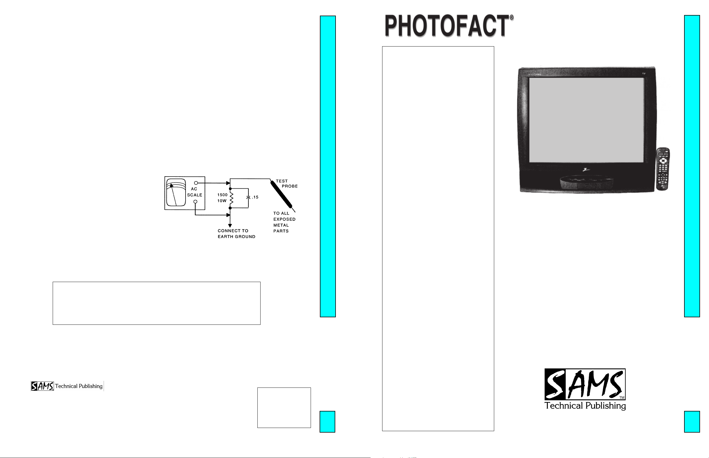
Hot LeakaHot Leaka
Hot Leaka
Hot LeakaHot Leaka
Plug the AC cord directly into an AC outlet. DO NOT use an isolation
transformer. Use a 1500 ohms, 10W resistor in parallel with a .15µF
capacitor to connect between any exposed metal parts on the receiver and
a good earth ground. (See figure below.) Use an AC voltmeter with at
least 5000 ohms per volt sensitivity to measure the voltage across the
resistor. Check all exposed metal parts and measure voltage at each point.
Voltage measurements should not exceed .75VAC, 500µA. Any value
exceeding this limit constitutes a potential shock hazard and must be
corrected. If the AC plug is not polarized, reverse the AC plug and repeat
exposed metal part voltage measurement at each point.
gg
e Chece Chec
e Chec
e Chece Chec
ks fks f
ks f
ks fks f
g
gg
gg
e Current Chece Current Chec
g
e Current Chec
gg
e Current Chece Current Chec
or Receiveror Receiver
or Receiver
or Receiveror Receiver
kk
k
kk
s with Isolated Grs with Isolated Gr
s with Isolated Gr
s with Isolated Grs with Isolated Gr
oundound
ound
oundound
SET 4703SET 4703
SET 4703SET 4703
SET 4703
MODEL B27B40ZMODEL B27B40Z
MODEL B27B40ZMODEL B27B40Z
MODEL B27B40Z
High Voltage Shutdown Test .................. 1
IC Functions ........................................... 4
Important Parts Information ................... 3
Miscellaneous Adjustments .................... 1
Parts List ................................................. 4
Placement Chart ..................................... 1
Safety Precautions .................................. 1
Schematic Component Location ............ 3
Schematic Notes ..................................... 3
Schematics
A/V .................................................. 3
Audio ............................................... 2
PIP IF .............................................. 3
Power Supply .................................. 2
System Control ................................ 3
Television ........................................ 2
Service Mode Adjustment Chart ............ 1
Test Equipment....................................... 3
Tuner Information .................................. 1
INDEXINDEX
INDEX
INDEXINDEX
Technical Service Data
ZENITHZENITH
ZENITH
ZENITHZENITH
Model B27B40ZModel B27B40Z
Model B27B40Z
Model B27B40ZModel B27B40Z
Representative Model
ff
or seror ser
f
or ser
ff
or seror ser
Essential coEssential co
Essential co
Essential coEssential co
vicing a televicing a tele
vicing a tele
vicing a televicing a tele
ScSc
hematicshematics
•
Sc
hematics
ScSc
hematicshematics
veravera
gg
vera
veravera
vision receivervision receiver
vision receiver
vision receivervision receiver
ee
g
e
gg
ee
......
...
......
4703
HIGH HIGH
VV
OLOL
TT
AA
HIGH
V
HIGH HIGH
VV
Turn receiver on, adjust customer controls for normal operation. Temporarily apply an external bias of
14.0V to the emitter of QX3002. The receiver should lose raster. If the receiver does not lose raster the
shutdown circuit should be repaired. Remove AC power, wait 30 seconds and test for normal operation.
The listing of any available replacement part herein in no case constitutes a recommendation, warranty, or guarantee by
SAMS Technical Publishing as to the quality and suitability of such replacement part. The numbers of the listed parts have
been compiled from information furnished to SAMS Technical Publishing by the manufacturers of the specific type of
replacement part listed.
Reproduction or use, without express permission, of editorial or pictorial content, in any manner, is prohibited. No patent
liability is assumed with respect to the use of the information contained herein.
© 2003
5436 West 78th Street
Indianapolis, IN 46268-4149
Printed in the United States of America 5 4 3 2 1
PP
aa
gg
e 1e 1
a
g
e 1
aa
gg
e 1e 1
SET 4703 SET 4703
SET 4703
SET 4703 SET 4703
P
PP
GE SHUTDOGE SHUTDO
OL
T
A
GE SHUTDO
OLOL
TT
AA
GE SHUTDOGE SHUTDO
WN WN
TESTTEST
WN
TEST
WN WN
TESTTEST
03PF02083
UPC
HERE
4703
ZENITHZENITH
ZENITHZENITH
ZENITH
For Supplier AdFor Supplier Ad
For Supplier Ad
For Supplier AdFor Supplier Ad
See PHOSee PHO
See PHO
See PHOSee PHO
TT
T
TT
OFOF
OF
OFOF
AA
CT AnnCT Ann
A
CT Ann
AA
CT AnnCT Ann
dress,dress,
dress,
dress,dress,
ual Indeual Inde
ual Inde
ual Indeual Inde
Component locationsComponent locations
•
Component locations
Component locationsComponent locations
PP
arar
ts listts list
•
P
ar
ts list
PP
arar
ts listts list
4703
xx
x
xx
MARCH MARCH
MARCH
MARCH MARCH
2003 SET 4703 2003 SET 4703
2003 SET 4703
2003 SET 4703 2003 SET 4703
Page 2

PP
aa
gg
e 1e 1
g
e 1
aa
gg
e 1e 1
SET 4703 SET 4703
SET 4703
SET 4703 SET 4703
P
a
PP
TUNER INFORMATION
MAIN MAIN
TUNER TUNER
MAIN
TUNER
MAIN MAIN
TUNER TUNER
PinPin
Pin
PinPin
(1) AGC 2.2V 2.0V 1.7V
(2) TU 1.2V 4.1V 6.0V
(3) EN/AS 1.2V 1.2V 1.2V
(4) CLK 4.8V 4.8V 4.8V
(5) DATA 4.8V 4.8V 4.8V
(6) 9V 0V 0V 0V
(7) 5V 5.0V 5.0V 5.0V
(8) LOCK 0V 0V 0V
(9) 33V 33.5V 33.5V 33.5V
(10) IF2 0V 0V 0V
(11) IF OUT 0V 0V 0V
NOTE: VHF Low Band voltages taken on channel 2.
VHF LoVHF Lo
VHF Lo
VHF LoVHF Lo
VHF High Band voltages taken on channel 7.
UHF Band voltages taken on channel 14
SUB SUB
SUB
SUB SUB
w Bandw Band
w Band
w Bandw Band
TUNER TUNER
TUNER
TUNER TUNER
VV
OLOL
TT
AA
V
VV
VV
V
VV
GE CHARGE CHAR
OL
T
A
GE CHAR
OLOL
TT
AA
GE CHARGE CHAR
VHF High BandVHF High Band
VHF High Band
VHF High BandVHF High Band
OLOL
TT
AA
GE CHARGE CHAR
OL
T
A
GE CHAR
OLOL
TT
AA
GE CHARGE CHAR
TT
T
TT
TT
T
TT
UHF BandUHF Band
UHF Band
UHF BandUHF Band
MAIN MAIN
MAIN
MAIN MAIN
SUB SUB
SUB
SUB SUB
TUNER TUNER
TUNER
TUNER TUNER
(2)
(4)
(6)
(8)
(10)
TUNER TUNER
TUNER
TUNER TUNER
TERMINAL GUIDETERMINAL GUIDE
TERMINAL GUIDE
TERMINAL GUIDETERMINAL GUIDE
(1)
τ
τ
(3)
τ
τ
(5)
τ
τ
(7)
τ
τ
(9)
τ
τ
(11)
τ
TERMINAL GUIDETERMINAL GUIDE
TERMINAL GUIDE
TERMINAL GUIDETERMINAL GUIDE
MISCELLANEOUS ADJUSTMENTS
This receiver employs digital customer controls which are accessed through
the service menu. All adjustments were performed at reset unless otherwise
indicated. Record all the data values for all functions in the service menu
before making any changes.
HIGH HIGH
VV
OLOL
TT
AA
V
OL
VV
OLOL
GE CHECKGE CHECK
T
A
GE CHECK
TT
AA
GE CHECKGE CHECK
HIGH
HIGH HIGH
Tune in a picture. Set brightness and color to minimum. Connect a high
voltage probe to CRT anode. High voltage should read from 27kV to 29kV.
SERSER
VICE MENUVICE MENU
SER
VICE MENU
SERSER
VICE MENUVICE MENU
To access the service menu adjustments by using the remote transmitter
keypad, press and hold the menu button until the menu display disappears
from the screen. Key in 9, 8, 7, 6, and press the enter button.
To access the service menu adjustments by using the receiver keypad, press
the menu button until the display disappears from the screen. Without
releasing the menu button simultaneously press the adjust right and channel
up buttons.
The receiver is now in service menu mode with function 03 H Pos 16
displayed. The first line on the service menu is a version number of the
software used in the receiver. On the bottom is a date the module went
through the factory. Use the select up and down buttons to select function.
Use the adjust buttons to make changes to selected function. The function
00 F Mode (Factory Mode) is always set to 0. Only the first seven items in
the service menu can be brought up. Use the select key to select the 00 F
Mode function and change the adjustment to 1, now all the menu items will
be accessible.
NOTE: Set value of function 00 F Mode (Factory Mode) to 0 before exiting
the service menu mode. If not set to 0 the receiver will not shut off with the
remote or power button on the receiver.
HORIZONTHORIZONT
HORIZONT
HORIZONTHORIZONT
Tune in a crosshatch pattern. Call up service menu, select function 11, set
data value for slight overscan on both sides.
RF ARF A
RF A
RF ARF A
Tune in a picture. Adjust R1202 to a point where snow appears in picture,
then to a point where snow disappears.
COLOR COLOR
COLOR
COLOR COLOR
Tune in a crosshatch pattern. Set brightness, picture, and color to minimum.
Call up service menu, select functions 27, 28, and 29, set data values to 0.
Adjust data values for functions 30, 31, and 32 of the two least predominate
colors to obtain a white pattern. Tune in an active black and white channel
and adjust functions 27, 28, and 29 for best white to black tracking at high
and low brightness.
COLOR PURITY / CONVERGENCECOLOR PURITY / CONVERGENCE
COLOR PURITY / CONVERGENCE
COLOR PURITY / CONVERGENCECOLOR PURITY / CONVERGENCE
CRT and yoke are bonded. Color purity and convergence adjustments are
not recommended.
GCGC
GC
GCGC
TEMPERATEMPERA
TEMPERA
TEMPERATEMPERA
AL SIZEAL SIZE
AL SIZE
AL SIZEAL SIZE
TURETURE
TURE
TURETURE
PinPin
Pin
PinPin
(1) AGC 2.3V 2.1V 1.8V
(2) TU 1.2V 4.0V 6.0V
(3) EN/AS 1.2V 1.2V 1.2V
(4) CLK 4.8V 4.8V 4.8V
(5) DATA 4.8V 4.8V 4.8V
(6) 9V 0V 0V 0V
(7) 5V 5.0V 5.0V 5.0V
(8) LOCK 0V 0V 0V
(9) 33V 33.3V 33.3V 33.3V
(10) IF2 0V 0V 0V
(11) IF OUT 0V 0V 0V
NOTE: VHF Low Band voltages taken on channel 2.
VHF High Band voltages taken on channel 7.
UHF Band voltages taken on channel 14
VHF LoVHF Lo
VHF Lo
VHF LoVHF Lo
w Bandw Band
w Band
w Bandw Band
VHF High BandVHF High Band
VHF High Band
VHF High BandVHF High Band
UHF BandUHF Band
UHF Band
UHF BandUHF Band
(2)
(4)
(6)
(8)
(10)
(1)
τ
τ
(3)
τ
τ
(5)
τ
τ
(7)
τ
τ
(9)
τ
τ
(11)
τ
Page 3

SERVICE MODE ADJUSTMENT CHART
SET 4703 PSET 4703 P
SET 4703 P
SET 4703 PSET 4703 P
aa
gg
e 1e 1
a
g
e 1
aa
gg
e 1e 1
FUNCTIONFUNCTION
FUNCTION
FUNCTIONFUNCTION
221-01389221-01389
221-01389
221-01389221-01389
00 F Mode 0 0 0 - 1 Factory Mode. Normal setting is 0, when set to 1, all other functions are accessible.
01 Pre Px 0 1 0 - 1 Stores customer video menu picture preference (P RESET). 0 is custom,
02 V Pos 15 16 0 - 30 Vertical position of On Screen Displays (Menus & Captions).
03 H Pos 42 42 0 - 80 Horizontal position of On Screen Displays (Menus & Captions).
04 Level 1 1 0 - 2 05 Band 0 0 0 - 7 This setting depends upon input signal. 0 Broadcast Fixed, 1 CATV AFC,
06 AC On 0 0 0 - 1 Enables AC Power On feature.
07 RF Brt 15 14 0 - 31 RF Brightness.
08 Ax Brt 15 14 0 - 31 Auxiliary Brightness.
09 Max Con 63 35 0 - 63 Maximum Contrast.
10 V Size 38 24 0 - 63 Vertical Size.
11 H Size 63 31 0 - 63 Horizontal Size.
12 V Phase 42 46 0 - 63 Vertical Phase.
13 H Phase 0 13 0 - 63 Horizontal Phase.
14 H Osc 7 9 0 - 31 Horizontal Osc.
15 S Corr 7 7 0 - 31 S Correction.
16 V Linea 7 7 0 - 15 Vertical Linearity.
17 Pin Amp 63 23 0 - 63 Pin Amp.
18 C Pin 63 30 0 - 63 Corner Pin.
19 Trapez 15 7 0 - 15 Trapezium.
20 EHT Com 7 15 0 - 15 EHT Comp.
21 AFC Bow 7 7 0 - 15 AFC Bow.
22 AFC Ang 7 7 0 - 15 AFC Angle.
23 Up V Lin 6 6 0 - 15 Upper Vertical Linearity.
24 Lo V Lin 0 0 0 - 15 Lower Vertical Linearity.
25 AFC G 1 0 0 - 3 AFC Gain.
26 EWDC 1 0 0 - 1 EWDC.
27 R Cut 0 8 0 - 15 Red Cutoff.
28 G Cut 0 1 0 - 15 Green Cutoff.
29 B Cut 0 0 0 - 15 Blue Cutoff.
30 R Gain 31 48 0 - 63 Red Gain.
31 G Gain 31 35 0 - 63 Green Gain.
32 B Gain 31 30 0 - 63 Blue Gain.
33 Dynam C 0 0 0 - 1 Dynamic C Video.
34 Gamma 0 0 0 - 3 Gamma Register.
35 DCTran 1 1 0 - 1 DCTran Video.
36 C Bpf 1 0 0 - 1 C Bpf Video.
37 C Trap 1 1 0 - 1 C Trap Off Video.
38 FSC Sw 0 0 0 - 1 FSC Sw Video.
39 ABL Mode 1 1 0 - 1 ABL Mode Video.
40 ABLVTH 1 1 0 - 1 ABLVTH Video.
41 6 Keys 1 1 0 - 1 Set to 0 for the 10 key keyboard, set to 1 for the 6 key keyboard.
42 A Att 9 7 0 - 15 Audio Input Attenuator.
43 A VCO 31 31 0 - 63 Audio Voltage Controlled Oscillator.
44 A Filter 31 27 0 - 63 Audio Filter.
45 ASpectral 31 12 0 - 63 High Frequency Separation.
46 W Band 31 31 0 - 63 Low Frequency Separation.
DD
AA
TT
D
A
T
DD
AA
TT
VV
ALUEALUE
V
ALUE
VV
ALUEALUE
AA
A
AA
ON-SETON-SET
ON-SET
ON-SETON-SET
VV
ALUEALUE
V
ALUE
VV
ALUEALUE
VV
ALUEALUE
V
ALUE
VV
ALUEALUE
RANGERANGE
RANGE
RANGERANGE
NONO
TESTES
NO
TES
NONO
TESTES
1 is preset stored.
3 ICC AFC, 4 Broad cast AFC, 5 CATV F ixed, 6 HRC Fixed, 7 ICC Fixed.
FUNCTIONFUNCTION
FUNCTION
FUNCTIONFUNCTION
221-01389221-01389
221-01389
221-01389221-01389
47 PIP X1 17 20 0 - 254 Horizontal position on left side.
48 PIP Y1 25 23 0 - 254 Vertical position on left side.
49 PIP X2 113 117 0 - 254 Horizontal position on right side.
50 PIP Y2 143 151 0 - 254 Vertical position on right side.
51 PIP Adj 2 3 0 - 15 Picture In Picture Adjustment.
52 PIP Y DL 4 1 0 - 15 Picture In Picture Y Delay.
53 PIP Y Off 31 31 0 - 31 Picture In Picture Y Offset.
54 PIP ACC 20 20 0 - 63 Picture In Picture ACC Level.
55 P BGST 10 10 0 - 63 Picture In Picture BG Stat Level.
56 PIP HX 22 25 0 - 63 Picture In Picture HX.
57 PIP VXS 37 38 0 - 63 Picture In Picture VXS.
58 PIP R Con 50 14 0 - 63 Picture In Picture Red Contrast.
59 PIP G Con 50 15 0 - 63 Picture In Picture Green Contrast.
60 PIP B Con 50 17 0 - 63 Picture In Picture Blue Contrast.
61 PIP Comp 2 2 0 - 3 Picture In Picture Comp.
62 YUV Brt 10 0 0 - 31 YUV Sub-Brightness.
63 Min Con 10 25 0 - 31 Minimum Contrast Value.
64 F Jacks 1 1 0 - 1 Front Jacks.
65 PIP Brt 200 201 0 - 254 Picture In Picture Brightness.
66 Xtal 0 0 0 - 1 Select Crystal or RC circuit Oscillator for OSD.
67 Min Brt 25 25 0 - 63 Custom Minimum Brightness.
68 Max Brt 35 35 0 - 63 Custom Maximum Brightness.
69 GM PIP X 15 15 0 - 50 PIP X position for gemstar.
70 GM PIP Y 17 17 0 - 30 PIP Y position for gemstar.
71 GM Pos X 36 36 0 - 60 OSD X position for gemstar.
72 GM Pos Y 13 13 0 - 36 OSD Y position for gemstar.
73 GM Siz X 110 110 0 - 152 OSD X Size for gemstar.
74 GM Siz Y 100 100 0 - 233 OSD Y Size for gemstar.
75 Mut Brt 20 20 0 - 63 Level Brightness when mute.
76 Mut Con 20 20 0 - 63 Level Contrast when mute.
77 GMVSize 30 30 0 - 63 GMVSize.
DD
AA
TT
D
A
T
DD
AA
TT
VV
ALUEALUE
V
ALUE
VV
ALUEALUE
AA
A
AA
ON-SETON-SET
ON-SET
ON-SETON-SET
VV
ALUEALUE
V
ALUE
VV
ALUEALUE
VV
ALUEALUE
V
ALUE
VV
ALUEALUE
RANGERANGE
RANGE
RANGERANGE
NONO
NO
NONO
TESTES
TES
TESTES
Page 4

ZENITH MODEL B27B40Z
ZENITH MODEL B27B40ZZENITH MODEL B27B40Z
ZENITH MODEL B27B40ZZENITH MODEL B27B40Z
SET 4703 PSET 4703 P
SET 4703 P
SET 4703 PSET 4703 P
aa
gg
e 1e 1
a
g
e 1
aa
gg
e 1e 1
Page 5
PP
aa
gg
e 2e 2
g
gg
e 2
e 2e 2
SET 4703 SET 4703
SET 4703
SET 4703 SET 4703
P
a
PP
aa
Page 6

SET 4703 PSET 4703 P
SET 4703 P
SET 4703 PSET 4703 P
aa
gg
e 2e 2
a
g
e 2
aa
gg
e 2e 2
Page 7

PP
aa
gg
e 2e 2
a
g
e 2
aa
gg
e 2e 2
SET 4703 SET 4703
SET 4703
SET 4703 SET 4703
P
PP
Page 8

ZENITH MODEL B27B40Z
ZENITH MODEL B27B40ZZENITH MODEL B27B40Z
ZENITH MODEL B27B40ZZENITH MODEL B27B40Z
SET 4703 PSET 4703 P
SET 4703 P
SET 4703 PSET 4703 P
aa
gg
e 2e 2
a
g
e 2
aa
gg
e 2e 2
Page 9

PP
aa
gg
e 3e 3
a
g
e 3
aa
gg
e 3e 3
SET 4703 SET 4703
SET 4703
SET 4703 SET 4703
P
PP
Page 10

SET 4703 PSET 4703 P
SET 4703 P
SET 4703 PSET 4703 P
ImporImpor
tant Ptant P
arar
ts Infts Inf
Impor
tant P
ImporImpor
ν The parts listed here are those not usually available from a well-stocked supply cabinet or bin.
ν Where items may be replaced with equivalent parts, several alternates are shown from participating vendors.
ν On the parts lists, safety items are marked with a
these items.
ν When ordering parts, state the model number, part number, and description.
ar
tant Ptant P
arar
# #
# to remind you that only exact replacements are recommended for
# #
ts Inf
ts Infts Inf
ormationormation
ormation
ormationormation
aa
gg
e 3e 3
a
g
e 3
aa
gg
e 3e 3
Obtaining PObtaining P
Obtaining P
Obtaining PObtaining P
Many of these parts are available from your local Sams authorized distributor or the manufacturer of the equipment. Call
Sams for the name of your nearest distributor:
arar
ar
arar
tsts
ts
tsts
800-428-7267
Or consult the Sams
Information on test equipment and replacement parts is listed in these pages for the following participating vendors.
Consult the Sams
ν NTE Electronics, Inc. (NTE)
Test equipment listed by participating manufacturer illustrates typical or equivalent equipment used by Sams engineers to obtain
measurements. This equipment is compatible with most types used by field service technicians.
EquipmentEquipment
Equipment
EquipmentEquipment
Oscilloscope SC3100
Generators
RGB CM2125
Multiburst Signal VG91
Color Bar VG91
TV Stereo VG91
Digital VOM SC3100
Frequency Meter SC3100
Hi-Voltage Probe HP200
Accessory Probes TP212
Annual Index
Annual Index
for the address of the original equipment manufacturer.
PP
arar
ticipating ticipating
P
ar
ticipating
PP
arar
ticipating ticipating
for their current address.
TEST EQTEST EQ
TEST EQ
TEST EQTEST EQ
Sencore No.Sencore No.
Sencore No.
Sencore No.Sencore No.
VV
endorendor
endor
endorendor
ss
s
ss
V
VV
ν Sencore, Inc.
UIPMENTUIPMENT
UIPMENT
UIPMENTUIPMENT
EquipmentEquipment
Equipment
EquipmentEquipment
Isolation Transformer PR570
Capacitance Analyzer LC102
CRT Analyzer CR7000
AC Leakage Tester PR570
Inductance Analyzer LC102
Flyback Yoke Tester TVA92
Field Strength Meter SL753
Transistor Tester TF46
Horizontal Analyzer HA-2500
Video Analyzer VG91, TVA92
Sencore No.Sencore No.
Sencore No.
Sencore No.Sencore No.
Page 11

PP
aa
gg
e 3e 3
a
g
e 3
aa
gg
e 3e 3
SET 4703 SET 4703
SET 4703
SET 4703 SET 4703
SET 4703 PSET 4703 P
SET 4703 P
SET 4703 PSET 4703 P
aa
gg
e 3e 3
a
g
e 3
aa
gg
e 3e 3
P
PP
Page 12

SCHEMASCHEMA
SCHEMA
SCHEMASCHEMA
TIC COMPONENT LOCATIC COMPONENT LOCA
TIC COMPONENT LOCA
TIC COMPONENT LOCATIC COMPONENT LOCA
TION GUIDETION GUIDE
TION GUIDE
TION GUIDETION GUIDE
C1 A41
C822 C30
C823 D31
C832 D30
C833 C31
C842 D23
C843 B29
C844M E23
C850 E24
C851 A28
C852 A31
C853 A31
C855M C28
C856M E23
C857 E24
C861 B28
C862 B30
C863 B30
C865M D28
C1200M C3
C1201M B2
C1202M B1
C1203M B24
C1204 B24
C1205M B2
C1206M C3
C1207M B3
C1208 B3
C1209 B2
C1210M A2
C1211M B5
C1212M C5
C1213 B5
C1214M B6
C1215M B3
C1216M B3
C1219M A4
C1220M A4
C1230 E18
C1231M E18
C1232 D23
C1233M D23
C1236 C1
C1240 B37
C1241M B38
C1242 D24
C1243M B38
C1244M B38
C1250 B45
C1253M C46
C1254M D24
C1255M A24
C1256 A23
C1257 D24
C1258 C45
C1259M D46
C1260M B46
C1261M C46
C1262M D48
C1263M A45
C1264M A46
C1265M B47
C1266 B23
C1267M B24
C1268M B46
C1269M E47
C1270 C46
C1271M C48
C1272M D48
C1273M C46
C1274 C47
C1276M B47
C1277M B48
C1278 A49
C1279M B49
C1280 B51
C1281M A50
C1282M A50
C1285 C48
C1290 A5
C1292 B48
C1294 B24
C1401M C27
C1402M D25
C1403M C26
C1404M D26
C1406M D25
C1413 B25
C1414 C26
C1415 D25
C1416 C27
C1417 D27
C1418 D25
C1419 C25
C1420 C25
C1421 C25
C1422 C25
C1424 E26
C1425 E26
C1426 D27
C1427 D27
C1428 E25
C1430 B24
C1431M D26
C1432 E27
C1433M B23
C1436 A26
C1479 E24
C1481 E24
C2103 E23
C2104 E23
C2106M D6
C2107 D8
C2108 A44
C2111 E22
C2112 E22
C2114 E21
C2201 B12
C2204 C12
C2206 E13
C2208M B11
C2209M B11
C2210M B11
C2213 B11
C2216M D1
C2217 D1
C2219M C11
C2220M C11
C2222M C10
C2223M B9
C2224M A9
C2225M B9
C2226M D3
C2227 D3
C2233M B11
C2234 B10
C2235M B10
C2236M C12
C2237 B12
C2238M C12
C2239 C12
C2240M C11
C2241M D2
C2245 C10
C2247M C8
C2248M B8
C2249M B8
C2250 B8
C2251 C24
C2290 C37
C2442M C37
C2450 C24
C2459 D37
C2461M C38
C2471M D39
C2471M D39
C2901 C35
C2902 C35
C2903 C35
C2905M D36
C2907 D35
C2908M D35
C2912 B24
C2923M E35
C2924M D36
C2925 C37
C2926 C36
C2927 C36
C2928M D36
C2929M D36
C2930M E36
C2932 A34
C2933 A34
C2934M E36
C2935 A2
C2936M A2
C2938M C37
C3201M E4
C3202 E4
C3203 E6
C3204 E5
C3206 E7
C3209 E21
C3219 E4
C3419 A21
C3421 B20
C3422 D24
C3423 D22
C3425 C21
C3426 C22
C3429 B24
C3433 B22
C3434 C23
C5100 E24
C5101 D15
C5103 E15
C5104 D15
C5105 C24
C5106 D16
C5121M A14
C5141M C14
C5161M B14
C5164 D15
C6001M D41
C6002M A43
C6003M A42
C6004M D43
C6005M A41
C6006 B42
C6007M D41
C6008M E41
C6009M E41
C6010M E41
C6011M E42
C6012M C23
C6013 C23
C6014M E41
C6015M E41
C6016 D41
C6017M C23
C6018M E44
C6019M E43
C6020 C44
C6021M C44
C6022M B42
C6023M D43
C6024M B43
C6025M A43
C6026M E5
C6033M A43
C6034M C42
C6036M C24
C6037 C24
C6038M B43
C6039M D43
C6040M B43
C6041M C49
C6042M B42
C6043M C42
C6044 D42
C6045M E44
C6046M D43
C6047M C43
C6048M C43
C6049M B43
C6050M C43
C6052M E43
C6053M E43
C6054M D42
C6055M A42
C6056M D42
C6058M C41
C6059M B42
C6060M A51
C6061M A42
C6062M E43
C6063M B43
C6064M D44
C6065M D43
C6068M E43
C6091M D44
CR1200 A3
CR1250 D47
CRY2201 B11
CRY6001 E42
CX841 D23
CX854 A31
CX864 B31
CX2100 E24
CX2101 E24
CX2102 D7
CX2105 D8
CX3001M D1
CX3002 D17
CX3003 E18
CX3205 E6
CX3207A E11
CX3208 E22
CX3210 D10
CX3211 D10
CX3212 E8
CX3215 D9
CX3216 E10
CX3217 E9
CX3218 E9
CX3253 E18
CX3254 E17
CX3257 E7
CX3400 C19
CX3401 A17
CX3402 A18
CX3403 A19
CX3404 A19
CX3405 A19
CX3406 A19
CX3407 A19
CX3408 B18
CX3409 C17
CX3410 C17
CX3412 B18
CX3415 D18
CX3416 D18
CX3420 A22
CX3424 B21
CX3427 C21
CX3428 A21
CX3430 B22
CX3436 B24
D2101 D7
D2102 D6
D2103 A43
D2206 B13
D2207 C13
D2208 B13
D2211 C11
D2212 C11
D2213 C10
D2214 B23
D3409 C20
D3410 A21
D3411 A20
D3416 B22
D3417 C21
D5101 D16
D5121 A14
D5122 A14
D5141 C14
D5142 C14
D5161 B14
D5162 B14
D6001 D42
D6002 A1
D6003 C49
DL2400 D38
DX2104 E22
DX2105 E21
DX3001 D1
DX3002 E17
DX3201 E21
DX3202 E7
DX3203 E9
DX3204 E8
DX3252 E17
DX3401 A19
DX3402 A19
DX3403 A19
DX3404 A19
DX3405 B17
DX3406 C18
DX3407 C18
DX3418 D22
DY1 D9
EX3401 A17
FX3401 A17
FX3402 A20
FX3403 D22
IC803 C30
IC804 A30
IC1200 B3
IC1250 B47
IC1400 A26
IC2200 B9
IC2200 D1
IC2900 B36
IC6000 B42
IC6001 C44
IC6002 D41
ICX2100 D7
ICX3401 A22
ICX3402 C22
ICX3403 D17
ICX3405 C23
ICX3406 D17
ICX3412 B18
IR1 A41
J1 C32
J1 C33
KX3401 B18
L1200 B1
L1201 A3
L1202 C5
L1203 C4
L1204 A3
L1250 C46
L1251 D46
L1252 A46
L1253 E46
L1254 D48
L1255 E46
L2201 E4
L2202 C12
L2203 B8
L2204 C8
L2205 C37
L2410 C37
L2411 D39
L2901 A2
L3200 A18
L3406 C21
L3407 C22
L3408 B21
L3409 B23
L3410 E22
L3411 E23
L3412 D22
L3414 A21
L3499 C23
L5101 C16
L5121 B14
L5122 A15
L5141 C14
L5142 C15
L5161 B14
L5162 B15
L6001 C22
L6002 E41
L6003 C44
L6004 A41
L6005 D23
L6007 D42
LX3202 E7
LX3262 D9
LX3401 A17
LX3402 B18
LX3403 A21
LX3404 A20
LX3405 D22
LX3410 B18
LX3415 C20
LX3416 B23
LX3417 B18
P3401 A17
Q1200 B6
Q1240 B38
Q1241 B39
Q1251 A48
Q1252 A50
Q1253 A49
Q1290 A7
Q1291 B49
Q1292 C49
Q1293 B6
Q2202 D14
Q2205 A13
Q2206 C13
Q2207 B13
Q2209 D13
Q2211 D11
Q2901 A37
Q2902 B37
Q2903 A38
Q2904 B37
Q3201 E4
Q3202 E5
Q3402 C21
Q3403 B17
Q3404 B21
Q3405 B23
Q5101 D16
Q5121 A14
Q5122 A14
Q5123 B15
Q5124 A15
Q5141 C14
Q5142 C14
Q5143 C15
Q5144 C15
Q5161 B14
Q5162 B14
Q5163 B15
Q5164 B15
Q6001 D41
Q6002 D6
Q6003 D44
Q6004 D5
QX3001 D2
QX3002 E1
QX3203 E7
R1 A41
R2 A41
R3 A41
R4 C41
R5 B41
R6 B41
R7 B41
R8 B41
R9 B41
R10 B41
R11 C41
R12 C41
R13 C41
R14 C41
R15 C41
R822M D31
R823M D31
R824M D31
R825 D31
R826M D30
R832M C31
R833M C31
R834M C31
R835 C31
R836M C30
R851M A28
R852M C29
R858 A31
R859 B31
R861M B27
R862M B27
R868 B31
R869 B30
R870 B29
R1201M B1
R1202 C3
R1203M C3
R1204 C1
R1205M C1
R1206 A2
R1207M A2
R1208M A2
R1209M C4
R1210M B4
R1211M C5
R1212M C5
R1213M B6
R1214 B6
R1216M B6
R1217M A4
R1222M A5
R1223M A4
R1224M A4
R1225M C4
R1226M C4
R1230M C44
R1231M B44
R1240M B37
R1241M D23
R1242M B38
R1243M B38
R1244M B38
R1245M B39
R1246M B39
R1250M C43
R1251M C43
R1256M B48
R1257M D46
R1258M B46
R1259M C46
R1260M D48
R1261 D48
R1262M A46
R1263M B46
R1264M B46
R1266M C48
R1267M C48
R1268 C49
R1269M E48
R1270M E46
R1271M C46
R1272M C46
R1273M A48
R1276M B48
R1278M A49
R1279M A49
R1280M B49
R1281M B49
R1282M A50
R1283M A50
R1284M B51
R1285M A50
R1288M A5
R1289M B48
R1290M B7
R1291M A6
R1292M A7
R1293M A6
R1294M B50
R1295M B49
R1296M B49
R1297M C49
R1298M B5
R1299 B23
R1401 B26
R1402 B25
R1404M B26
R1405M D25
R1406M C25
R1407M C25
R1408M E27
R1409M E27
R1421M A25
R1422M A25
R1425M C26
R2101M D5
R2102M D5
R2103M D5
R2104M D8
R2109M A44
R2112M A43
R2113M A43
R2201 D13
R2202 E13
R2203M D1
R2204M D12
R2206M A10
R2212 D13
R2213 E13
R2214M D2
R2215M A10
R2222M D2
R2224M E2
R2225M E3
R2226M E3
R2232M A12
R2233 B23
R2234M A13
R2235M C12
R2236 B23
R2237M C13
R2238M B12
R2240M B13
R2242 B11
R2244M D14
R2245M D14
R2246M D13
R2247M D14
R2250 B12
R2251 B12
R2252M B10
R2253M C12
R2257M B13
R2258M C13
R2259M A13
R2264M C11
R2265M C11
R2266M C11
R2271M A9
R2278M D11
R2279M D10
R2280 C10
R2283 B8
R2284M B8
R2287 D10
R2290 A9
R2291M B43
R2292M A43
R2293M A43
R2294M A43
R2295M A43
R2296M B43
R2460M D37
R2461M D37
R2463 C37
R2470M D39
R2470M D39
R2471M D39
R2901 C35
R2904 C35
R2906 C35
R2907 D34
R2908 D35
R2910 D35
R2911 D35
R2931M A33
R2932M A35
R2933M E35
R2934M B37
R2935M B37
R2936M B38
R2937M A37
R2938M A37
R2939M A38
R2940 D36
R2943M C36
R2944M E36
R2945M E36
R2953M A38
R2954M A36
R2955M A36
R2956M B37
R2957M B37
R2958M C37
R2960M C36
R2969M C35
R2970M C34
R3201M E4
R3202M E5
R3203 E4
R3204 E6
R3205 E6
R3218 E3
R3410 E21
R3411 E23
R3412M C21
R3414 C21
R3418M C20
R3419 B17
R3425M B23
R3426 C21
R5102 D16
R5103 D16
R5104 D16
R5105 D16
R5106 E16
R5107 D15
R5108 C24
R5109 D16
R5121M A14
R5122M A14
R5123M B14
R5124M B14
R5125M B14
R5141M C14
R5142 C14
R5143M C14
R5144M C14
R5145M C14
R5161 B14
R5162M B14
R5163M B14
R5164M B14
R5165 B14
R6001M D42
R6002M D42
R6003M D41
R6004 D41
R6005M E6
R6006M E43
R6007M E5
R6008M D5
R6009M C41
R6010 C49
R6011M B42
R6012M A42
R6013 A42
R6015M C41
R6016M B41
R6017M D43
R6023M D44
R6024M D43
R6027 A42
R6031M A42
R6032M D41
R6034M E42
R6035M E41
R6037M D41
R6039 E43
R6040M D43
R6041 C43
R6042 C43
R6043 B43
R6044 C43
R6045M C43
R6046M C43
R6047M B43
R6048M C43
R6049 C43
R6050 C43
R6051 A51
R6052M A51
R6058M D44
R6059M E42
R6060M E41
R6064 B41
R6068 A10
R6069M B42
R6070M C41
R6072M E43
R6080M E41
R6081M D43
R6088M D44
RX853 A31
RX863 B30
RX2105 D8
RX2106 D8
RX2107 D8
RX2110 D8
RX2111 D8
RX2124 E23
RX2125 E22
RX3001M D1
RX3002M D1
RX3003 E1
RX3004 E2
RX3005 E1
RX3007 E1
RX3206 E22
RX3207 E6
RX3208 E22
RX3209 D11
RX3210 A16
RX3211 E19
RX3212 E8
RX3214 D9
RX3215 E9
RX3216 E17
RX3400 B17
RX3401 A18
RX3403 C18
RX3404 C17
RX3405 C18
RX3406 C18
RX3407 C17
RX3408 D18
RX3409 D17
RX3413 A22
RX3416 B18
RX3417 B22
RX3421 D18
RX3423 C21
RX3427 D18
RX3428 D18
RX5126 B14
RX5127 B15
RX5128 A15
RX5129 A15
RX5130 A16
RX5146 C14
RX5147 C15
RX5148 C15
RX5149 C15
RX5150 C15
RX5166 C14
RX5167 C15
RX5168 B15
RX5169 B15
RX5170 B15
SP1 A32
SP2 B32
SW1 B41
SW2 C41
SW3 B41
SW4 C41
SW5 B41
THX3415 A18
TP6010 B44
TX3204 D12
TX3204 D20
TX3205 E6
TX3401 A20
U1200 B2
U1201 C4
U1202 C4
U1251 A46
U1252 E46
U1253 D46
V1 B16
ZD1230 E18
ZD1250 A24
ZD2201 D13
ZD2205 E2
ZD2901 D34
ZD2904 C35
ZD2906 D35
ZDX3004 E1
ZENITH MODEL B27B40Z
ZENITH MODEL B27B40ZZENITH MODEL B27B40Z
ZENITH MODEL B27B40ZZENITH MODEL B27B40Z
SET 4703 PSET 4703 P
SET 4703 P
SET 4703 PSET 4703 P
aa
gg
e 3e 3
a
g
e 3
aa
gg
e 3e 3
Page 13

PP
aa
gg
e 4e 4
a
g
e 4
aa
gg
e 4e 4
SET 4703 SET 4703
SET 4703
SET 4703 SET 4703
P
PP
Page 14

PARTS LIST
SET 4703 PSET 4703 P
SET 4703 P
SET 4703 PSET 4703 P
aa
gg
e 4e 4
a
g
e 4
aa
gg
e 4e 4
Item No.Item No.
Item No.
Item No.Item No.
D2101 1N4004 103-00347-03A NTE116
D2102, 03 1N4148 103-00461A NTE519
D2206, 07, 08 1N4148 103-00461A NTE519
D2211 Thru
D2214 1N4148 103-00461A NTE519
D3409 PR3004G 103-00339-04A NTE576
D3410, 11 MUR460 103-00589 NTE577
D3416 - 103-00347-03A D3417 1N4148 103-00461A NTE519
D5101 - 103-00344-06A D5121 1N4148 103-00461A NTE519
D5122 - 103-00415-02A D5141 1N4148 103-00461A NTE519
D5142 - 103-00415-02A D5161 1N4148 103-00461A NTE519
D5162 - 103-00415-02A D6001, 02, 03 1N4148 103-00461A NTE519
# DX2104, 05 PR3004G 103-00339-04A NTE576
# DX3001 1N4148 103-00461A NTE519
# DX3002 - 103-00344-06A # DX3201 - 103-00344-06A # DX3202 - 103-00305-01A # DX3203 - 103-00347-03A # DX3204 1N4148 103-00461A NTE519
# DX3252 - 103-00344-06A # DX3401 Thru
# DX3404 - 103-00588A # DX3405 - 103-00347-03A # DX3406 1N4148 103-00461A NTE519
# DX3407 - 103-00344-06A # DX3418 MUR460 103-00560-07 NTE577
IC803 TL072CP 221-00170 NTE858M
IC804 LA4282 F-53765 IC1200 TA1268N 221-00792 IC1250 LA7578N 221-00792-01 NTE7129
IC1400 CXA2054S 221-01127 IC2200 CXA2061S 221-01394 IC2900 TA8851CN 221-01053 IC6000 - 221-01428 IC6001 24C04PC 221-00745-05 IC6002 KIA7042P 221-01177A -
# ICX2100 LA7645N F-53864 -
# ICX3401 L7809ABV F-52599 NTE1910
# ICX3402 78L05ABV F-53046 NTE977
# ICX3403 P621 162-00028-01 NTE3098
# ICX3405 78L12 221-00167-05A NTE950
# ICX3406 KA431LZ 221-00265-03A -
# ICX3412 STR-53041 F-53857 NTE1840
Q1200, 40 2N3906 121-01311A NTE159
Q1241 2N3904 121-01310A NTE123AP
Q1251 2N3906 121-01311A NTE159
Q1252 2N3904 121-01310A NTE123AP
Q1253 2N3906 121-01311A NTE159
Q1290 Thru
Q1293 2N3904 121-01310A NTE123AP
Q2202 2N3906 121-01311A NTE159
Q2205, 06, 07 2N3904 121-01310A NTE123AP
Q2209 - 121-01390 NTE123AP
Q2211 2N3906 121-01311A NTE159
Q2901 Thru
Q2904 2N3904 121-01310A NTE123AP
Q3201 2N3904 121-01310A NTE123AP
Q3202 - 121-01264-01A NTE287
Q3402, 03 MPSA06 121-01340A NTE287
Q3404, 05 - 121-01102A NTE25
Q5101 MPSA42 121-01355A NTE287
Q5121 KTC3229 F-45300 NTE376%
Q5122 2N3904 121-01310A NTE123AP
Q5123 BF420 121-01374A NTE399
Q5124 BF421 121-01375A NTE288
Q5141 KTC3229 F-45300 NTE376%
Q5142 2N3904 121-01310A NTE123AP
Q5143 BF420 121-01374A NTE399
TT
ype No.ype No.
T
ype No.
TT
ype No.ype No.
MfrMfr
Mfr
MfrMfr
..
P P
arar
t No.t No.
.
P
ar
t No.
..
P P
arar
t No.t No.
NTE PNTE P
NTE P
NTE PNTE P
arar
ar
arar
t No.t No.
t No.
t No.t No.
Item No.Item No.
Item No.
Item No.Item No.
Q5144 BF421 121-01375A NTE288
Q5161 KTC3229 F-45300 NTE376%
Q5162 2N3904 121-01310A NTE123AP
Q5163 BF420 121-01374A NTE399
Q5164 BF421 121-01375A NTE288
Q6001, 02 2N3904 121-01310A NTE123AP
Q6003 - 121-01390 NTE123AP
Q6004 2N3904 121-01310A NTE123AP
# QX3001 2N3904 121-01310A NTE123AP
# QX3002 2N3906 121-01311A NTE159
# QX3203 2SD2499 F-53367 -
ZD1230, 50 - 103-00279-36A NTE5085A
ZD2201 - 103-00279-10A NTE5010A
ZD2205 - 103-00279-11A ZD2901 - 103-00279-10A NTE5010A
ZD2904, 06 - 103-00279-18A -
# ZDX3004 - 103-00472A NTE142A
Item No.Item No.
Item No.
Item No.Item No.
C1240, 78 1µF 20% 50V NP 022-08492-01A C1414 10µF 10% 50V 022-07669-15A C1416, 17 10µF 20% 25V NP 022-08188-05A C1419 3.3µF 10% 50V 022-07669-14A C1426, 27 10µF 20% 25V NP 022-08188-05A C2459 10µF 20% 25V NP 022-08188-05A C2925, 26, 27 10µF 20% 25V NP 022-08188-05A C3206 .001 10% 1kV 022-07811A C5103 .01 +80% -20% 2kV 022-07523-01B C5164 560pF 10% 2kV 022-08386-05 CR1200, 50 Crystal 224-00202A 4.5MHz
CRT1 Socket 078-03394-09 CRT
CRY2201 Crystal 224-00027A 3.58MHz
CRY6001 Crystal 224-00074-02A 8MHz
# CX841 1000µF 20% 35V 022-08311-16 -
# CX854, 64 1000µF 20% 16V 022-08309-16 -
# CX2100, 01 470µF 20% 25V 022-08310-15 -
# CX2102 220µF 20% 35V 022-08311-13 -
# CX2105 .1 10% 50V 022-08049-24A -
# CX3001M .01 10% 25V 022-08368-20A -
# CX3002 470pF 10% 500V 022-07786-10C -
# CX3003 47µF 20% 50V 022-08312-11A -
# CX3205 100µF 20% 50V 022-08312-12A -
# CX3207A .68 10% 200V 022-08159 -
# CX3208 10µF 20% 250V 022-08317-08 -
# CX3210, 11 560pF 10% 2kV 022-08386-05 -
# CX3212 .001 10% 2kV 022-08386-08 -
# CX3215 470pF 10% 500V 022-07786-10C -
# CX3216 .013 3% 1.6kV 022-08229-27 -
# CX3217 .39 5% 200V 022-08231-11 -
# CX3218 2.2µF 20% 160V 022-08315-05A -
# CX3253 47µF 20% 25V 022-08312-11A -
# CX3254 470pF 10% 500V 022-07786-10C -
# CX3257 .047 5% 50V 022-08227-07A -
# CX3400 .0047 20% 250VAC 022-07431-06B -
# CX3401 .1 20% 250VAC 022-07867-10 -
# CX3402 .0047 20% 250VAC 022-07431-06B -
# CX3403 Thru
# CX3406 .001 10% 1kV 022-07811A -
# CX3407 330µF 20% 200V 022-08444-09 -
# CX3408 .0022 10% 2kV 022-08386-12 -
# CX3409 .0022 10% 500V 022-07786-17C -
# CX3410 100µF 20% 25V 022-08310-12A -
# CX3412 .001 10% 2kV 022-08386-08 -
# CX3415 .022 5% 50V 022-08227-04A -
# CX3416 470pF 20% 50V 022-08257-08A -
# CX3420 220µF 20% 200V 022-08444-07 -
# CX3424, 27 2200µF 20% 25V 022-08310-17 -
# CX3428 470µF 20% 25V 022-08310-15 -
# CX3430 4.7µF 20% 50V 022-08312-07A -
# CX3436 470µF 20% 25V 022-08310-15 -
DL2400 Filter 223-00045 Comb
DY1 (1) Yoke - Horiz 1.3mH, Vert 16.6mH
TT
ype No.ype No.
T
ype No.
TT
ype No.ype No.
Function/RatingFunction/Rating
Function/Rating
Function/RatingFunction/Rating
MfrMfr
Mfr
MfrMfr
MfrMfr
Mfr
MfrMfr
..
P P
arar
t No.t No.
.
P
ar
t No.
..
P P
arar
t No.t No.
..
P P
arar
t No.t No.
.
P
ar
t No.
..
P P
arar
t No.t No.
NTE PNTE P
NTE P
NTE PNTE P
NotesNotes
Notes
NotesNotes
arar
ar
arar
t No.t No.
t No.
t No.t No.
Page 15

PARTS LIST continued
Item No.Item No.
Item No.
Item No.Item No.
# EX3401 Spark Gap 038-00102 4kV
# FX3401 Fuse 136-00114-23C 4Amp, 250V, Normal Lag
# FX3402, 03 Fuse 136-00148-23C 3Amp, 250V, Normal Lag
IR1 Receiver - Remote
J1 Jack A-19192 Assembly
# KX3401 Relay 195-00161 Degaussing
L1200 .27µH 020-04277-03A L1201 SIF 020-04493A L1202 VCO 020-04493A L1203 12µH 020-04277-23A L1204 15µH 020-04129-22 L1250 - - L1251 15µH 020-04129-22 L1252 .27µH 020-04277-03A L1253 AFC 020-04493A L1254 VCO 020-04493A L1255 12µH 020-04277-23A L2201 18µH 020-03907-15A L2202 6.8µH 020-04277-20A L2203, 04 4.7µH 020-04129-16 L2205 2.2µH 020-04277-14A L2410 6.8µH 020-04277-20A L2411 10µH 020-04277-22A L2901 100µH 020-03907-24A L3200 Degaussing 020-04330-43 L3406, 07 33µH 020-04462-18A L3408 56µH 020-03907-21A L3409 10µH 020-03907-12A L3410, 11 100µH 020-03907-24A L3412 56µH 020-03907-21A L3414 33µH 020-04462-18A L3499 - - L5101 Ferrite Bead F-47318 L5121, 22 22µH 020-04277-26A L5141, 42 22µH 020-04277-26A L5161, 62 22µH 020-04277-26A L6001 4.7µH 020-04129-16 L6002 1.8µH 020-04277-70A L6003, 04, 05 1µH 020-04129-08 L6007 4.7µH 020-04129-16 -
# LX3202 Ferrite Bead F-43283 -
# LX3262 Horizontal Linearity 020-04073-03 -
# LX3401 Line Filter 095-04593 -
# LX3402 Thru
# LX3405 Ferrite Bead F-43283 -
# LX3410 Ferrite Bead F-43283 -
# LX3415 Ferrite Bead 149-00549 -
# LX3416 56µH 020-03907-21A -
# LX3417 Ferrite Bead 149-00549 -
P3401 Line Cord A-18681-01 AC, Polarized
R1202, 61 10K AGC Delay 063-11007-34 R1404M 61.9K 1% 1/10W 063-11244-76A -
# RX853, 63 3.3 5% 1/4W 063-10559-12 -
# RX2105 3.3 5% 1/4W 063-10235-12 -
# RX2106, 07 680 5% 1/2W 063-10243-68 -
# RX2110, 11 3.3 5% 1/2W 063-11110-12 -
# RX2124, 25 .51 5% 1/2W 063-11214-16 -
# RX3001M 10K 5% 1/10W 063-11059-73A -
# RX3002M 33K 5% 1/10W 063-11059-85A -
# RX3003 3570 .1% 1/4W 063-11283-45 -
# RX3004 10K 5% 1/4W 063-10235-96 -
# RX3005 5620 1% 1/4W 063-10936-86 -
# RX3007 8200 5% 1/4W 063-10235-94 -
# RX3206 270K 5% 1/2W 063-10244-30 -
# RX3207 15 5% 1/2W 063-11087-28 -
# RX3208 2.7 5% 1/2W 063-10565-10 -
# RX3209 6.8 10% 10W 063-10460-44A -
# RX3210 4.7 5% 1W 063-10832-16B -
# RX3211 1 5% 1/2W 063-10565 -
# RX3212 2000 5% 1/4W 063-10235-79 -
# RX3214 22K 5% 1/2W 063-10244-04 -
# RX3215 750 5% 1W 063-10832-69B -
# RX3216 330 5% 2W 063-11160-60B -
Function/RatingFunction/Rating
Function/Rating
Function/RatingFunction/Rating
MfrMfr
Mfr
MfrMfr
..
P P
arar
t No.t No.
.
P
ar
t No.
..
P P
arar
t No.t No.
NotesNotes
Notes
NotesNotes
Item No.Item No.
Item No.
Item No.Item No.
# RX3400 5.6M 20% 1/2W 063-11264-01 -
# RX3401 .68 10% 5W 063-10444-20A -
# RX3403 .12 10% 3W 063-11235-01 -
# RX3404 4700 5% 1/4W 063-10235-88 -
# RX3405 680 5% 1/4W 063-10235-68 -
# RX3406 1800 5% 1/4W 063-10235-78 -
# RX3407 10 5% 1/4W 063-10559-24 -
# RX3408 182K .1% 1/4W 063-11285-09 -
# RX3409 1500 5% 1/4W 063-10235-76 -
# RX3413 22K 5% 1/2W 063-10244-04 -
# RX3416 47K 5% 3W 063-11165-12B -
# RX3417 6.2 5% 5W 063-10442-43B -
# RX3421 3570 .1% 1/4W 063-11283-45 -
# RX3423 .1 5% 1/2W 063-11214 -
# RX3427 1000 5% 1/4W 063-10235-72 -
# RX3428 330K 5% 1/4W 063-10236-32 -
# RX5126 6800 5% 3W 063-10840-92B -
# RX5127, 28, 29 100 5% 1/4W 63-10235-48 -
# RX5130 1000 5% 1/2W 063-10243-72 -
# RX5146 6800 5% 3W 063-10840-92B -
# RX5147, 48, 49 100 5% 1/4W 63-10235-48 -
# RX5150 1000 5% 1/2W 063-10243-72 -
# RX5166 6800 5% 3W 063-10840-92B -
# RX5167, 68, 69 100 5% 1/4W 063-10235-48 -
# RX5170 1000 5% 1/2W 063-10243-72 -
SP1, 2 Speaker 049-01368-03 6cm X 13cm, 8 Ohms, 5W
SW1 Switch - On/Off
SW2 Switch - Channel Up
SW3 Switch - Channel Down
SW4 Switch - Volume Up
SW5 Switch - Volume Down
SW6 Switch - Menu
# THX3415 13 Cold PTC 063-10710A -
# TX3204 (2) Horizontal Output 095-04606-04 -
# TX3205 Horizontal Driver 095-04477-01 -
# TX3401 SMT 095-04576 -
U1200 Filter 224-00148 SAW
U1201 Trap 224-00023A 4.5MHz
U1202 Filter 224-00139-01A 4.5MHz
U1251 Filter 224-00160 SAW
U1252 Filter 224-00023A 4.5MHz
U1253 Filter 224-00139-01A 4.5MHz
V1 - A-19112 A68AJB82X03
W0018 56µH 020-03907-21A W0088 33µH 020-4462-18a WT1200 Tuner 175-02770 Main
WT1250 Tuner 175-02770 Sub
# For SAFETY use only equivalent replacement part.
% Use insulating hardware supplied with replacement.
(1) Bonded part of CRT.
(2) Screen (G-2) and focus controls are part of TX3204.
Function/RatingFunction/Rating
Function/Rating
Function/RatingFunction/Rating
Module 009-02110 PIP
PC Board F-53039 Keyboard
Splitter - Antenna
Transmitter 124-00233-03 Remote, MBR3458Z
MfrMfr
Mfr
MfrMfr
..
P P
arar
t No.t No.
.
P
ar
t No.
..
P P
arar
t No.t No.
NotesNotes
Notes
NotesNotes
PP
aa
gg
e 4e 4
g
e 4
gg
e 4e 4
SET 4703 SET 4703
SET 4703
SET 4703 SET 4703
P
a
PP
aa
 Loading...