

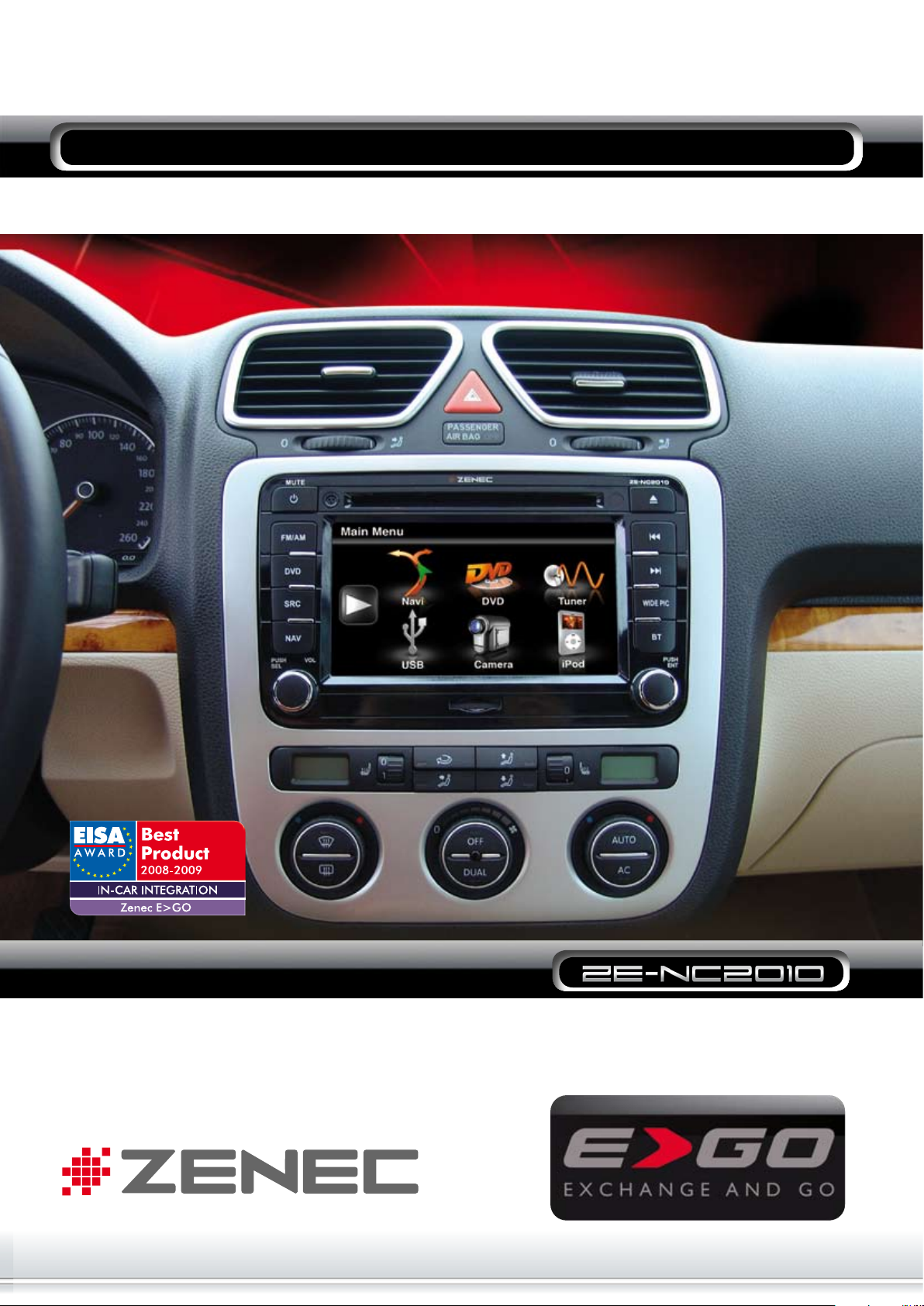
MOUNTING INSTRUCTIONS GOLF V
T OUCH ANOTHER W ORLD
MOUNTING INSTRUCTIONS
Bitte Beachten/Please Note
➜ Das Fahrzeug ist mit einem Eigendiagnosegerät (DME)
ausgestattet.
Um Fehlermeldungen zu vermeiden, muss vor
Montagebeginn unbedingt der negative Pol der
Fahrzeugbatterie abgehängt werden.
➜ Eine einwandfreie Funktion des ZE-NC2010 kann nur
dann gewährleistet werden, wenn Sie das im Lieferumfang
enthaltene Zubehör verwenden.
➜ Es ist nicht nötig, am originalen Anschlusskabel bzw.
Quadlockstecker Veränderungen irgendwelcher Art
vorzunehmen.
➜ Achten Sie bei der Installation darauf, das die
verschiedenen Anschlusskabel und Zubehörteile wie z.B
TMC-Empfänger nicht durch scharfe Kanten beschädigt
werden und die Anschlusskabel nicht geknickt werden.
➜ Im Auslieferungszustand ist das interne Mirkofon
aktiviert. Um das externe Mikrofon zu verwenden, müssen
Sie den violetten Stecker (No.7) mit der Kabelbrücke
entfernen, das externe Mikrofon im Setup des Bluetooth
Modus aktivieren und den ebenfalls violetten Stecker
mit dem externen Mikrofon anstelle der Kabelbrücke
einstecken.
Um wieder das interne Mikrofon zu verwenden, müssen
Sie die Kabelbrücke anstelle des Steckers mit dem
externen Mikrofon einstecken und im Setup des Bluetooth
Modus das interne Mirkofon wieder aktivieren. Eine
detaillierte Beschreibung des Bluetooth Modus finden Sie
in der ZE-NC2010 Bedienungsanleitung.
➜ Tampering with the on-board electrical system might
cause an error code to be stored in the DME.
It is thus recommended to disconnect the GND wire of
the negative battery pole before you start any installation
work.
➜ The flawless function of the ZE-NC2010 can only be
warranted, if you are using the original accessories, which
are included set content.
➜ It‘s not necessary to make any modifications on the
original connection cable resp. Quadlock connector.
➜ Take care during the installation to don’t damage the
different connection cables and accessories, for example
TMC module, caused by sharp edges and don’t snap off
the connection cables too much.
➜ Out of the box, the internal microphone is activated.
If you want to use the external microphone, remove the
violet connector (No.7) with the wire bridge, activate the
external microphone in the Bluetooth setup and add the
violet connector with the external microphone instead of
the wire bridge.
If you want to use the internal microphone again, add
the wire bridge instead the connector with the external
microphone and activate the internal microphone in the
Bluetooth setup again.
You will find a detailed description of the Bluetooth mode
in the main manual.
➜ Achten Sie vor der finalen Montage des ZE-NC2010
darauf, das alle Steckverbindungen richtig verbunden und
fest eingerastet sind.
➜ Einbauanleitungen für weitere Fahrzeuge finden Sie
unter www.zenec.com.
➜ Bei Fragen oder Problemen wenden Sie sich an
Ihren ZENEC-Händler, bei dem Sie das Gerät gekauft
haben. Zusätzlich finden Sie unter www.zenec.com eine
ausführliche FAQ Datenbank, wo viele der Fragen und
Probleme, welche während der Installation auftreten
könnten, entsprechend beantwortet werden.
➜ Da Updates (Software und Kartenmaterial) für das
Navigationssystem nur über USB-Anschluss installiert
werden können und sich der USB-Anschluss an der
Rückseite des ZE-NC2010 befindet, sollten Sie die im
Lieferumfang befindliche Media Link Box unbedingt
an einem leicht zugänglichen Ort installieren.
➜ Pls check if all plug-and-socket connections are
connected correctly and as the case may be, if they are
well engaged, before you start with the final installation of
the ZE-NC2010.
➜ You will find more mounting instructions for other cars
on www.zenec.com.
➜ Pls contact your ZENEC dealer or distributor where you
have bought the unit, if you have any problems or further
questions.
Additionally you will find a detailed FAQ data base on
www.zenec.com, where most of the questions and
problems which can appear during the installation are
answered.
➜ Because it’s only possible to update the navigation
system (software and map data) via USB and the
USB port is located at the backside, it’s necessary to
install the media link box, which is included in the set
content, to a place that is easy to access.

1
Für den optimalen Halt montieren Sie
1
die beiliegenden Führungsschienen
(No.12) mit den entsprechenden
Schrauben gemäss Packliste.
For best stability of the unit inside the
dashboard, please mount the die-cast
rails (No.12/packing list), using the
appropriate screws.
2
3
Das TMC-Modul (No.6) wird an das
2
ZE-NC2010 mit Mini-USB und dem
weißen Fakra-Stecker angeschlossen.
Danach wird der Antennen-Adapter
mit Phantomeinspeisung (No.11)
an das TMC-Modul angeschlossen.
Das blaue Kabel muss an das am
Stecker des Hauptanschlusskabel
(No.3) vorhandene Kabel „ P.ANT“
angeschlossen werden. Zum
Schluss wird das Antennenkabel des
Fahrzeuges an den Antennenadapter
angeschlossen.
Verbinden Sie nun den entsprechenden
3
Stecker des Hauptanschlusskabels mit
dem CAN-Bus Adapter (No.16).
Connect the TMC module (No.6)
via Mini-USB and the white Fakra
connector to the ZE-NC2010.
Then proceed to connect the antenna
adapter with antenna power supply
(No.11) to the TMC module.
It’s necessary to connect the blue cable
to the “P.ANT” connector of the main
connection cable (No.3).
Finally connect the antenna connector
of the car to the antenna adapter.
Now connect the appropriate connector
of the main connection cable with the
CAN Bus interface (No.16).
4
Das Hauptanschlusskabel (No.3)
4
wird, wie im Anschlussdiagramm
aufgelistet, angeschlossen. Dabei
sollten Sie darauf achten, das der im
Hauptanschlusskabel integrierte braune
8 polige Stecker entsprechend mit dem
ZE-NC2010 verbunden wird.
Connect the main connection cable as
described in the electrical connections
overview.
Take care to connect the brown 8-pin
connector, which is integrated in the
main connection cable (No.3), to the
ZE-NC2010.

5
6
Montage: Installation:
Hebeln Sie vorsichtig das Gitter
5
heraus. Beginnen Sie an der zur
Scheibe zugewandten Seite.
Lever up the metal mesh top cover.
Start with the side that is close to
the windshield.
8
7
9
Nachdem das Gitter abgenommen
6
wurde, trennen Sie den Stecker von
der Unterseite des Gitters.
Lösen Sie die Torx-Schraube. Unscrew the Torx head screw in the
7
Hebeln Sie nun vorsichtig das innere
8
Plastikteil aus der Verankerung.
Beginnen Sie an der zur Scheibe
zugewandten Seite.
Lösen Sie die zwei Torx-Schrauben. Unscrew the two Torx head screws.
9
After the metal mesh has come off,
proceed with unplugging the
connector underneath.
center.
Carefully lift the inner plastic part
out of its seating.
Here as well, start with the end
closest to the windshield.
bl
bm
Hebeln Sie die Lüftungsarmatur nur
bl
an der zur Scheibe zugewandten
Seite heraus. Drücken Sie dann die
Armatur vorsichtig nach oben.
Lösen Sie vorsichtig die 2 Torx-
bm
Schrauben der Zierblende, die
um das Radio und die Regler sitzt.
Beim lösen der Zierblende halten
Sie sich unbedingt an die vorgegebene Reihenfolge. Erst die rechte
Seite, dann die linke Seite.
1
Pull up the A/C plastic main frame
at the end that is nearest to the
windshield. Carefully push the A/C
assembly upwards.
Unscrew both Torx head screws
at the upper left and right side
of the trim part. Then remove the
U-shaped trim cover exactly in
the sequence as shown in the pic.
Start at the upper right end and
work towards the bottom and
around.
2
3
4

bn
bo
bp
Lösen Sie dann die 4 Torx-Schrau-
bn
ben, die das Radio fixieren und
ziehen Sie das Gerät heraus.
Lösen Sie die Verankerung des
bo
MOST-Steckers und ziehen Sie
diesen Hebel nach oben.
Ziehen Sie nun den MOST-Stecker
bp
vom Gerät. Lösen Sie nun noch
die zwei Antennenstecker.
Unscrew the four Torx head screws
that fix the radio to the dashboard.
Pull the head unit out.
The MOST plug on the backside of
the head unit can be unlocked by
lifting the lever up towards the
wires.
Pull out the MOST plug and also
remove the two antenna plugs.
bq
Der Radio-Schacht ist nun frei.
bq
Es kann mit der Montage des
ZE-NC2010 begonnen werden.
Gehen Sie dazu in umgekehrter
Reihenfolge dieser Einbauanleitung
vor. Verbinden Sie den weissen
Antennenstecker mit dem Antennenanschluss des ZE-NC2010. Stellen
Sie sicher, das Sie alle benötigten
Kabel der Media-Link-Box oder der
Rückfahrkamera angeschlossen
haben. Der Anschlussplan gibt Ihnen
Auskunft über weitere Anschlussmöglichkeiten.
The dashboard is now ready for
the install of the ZE-NC2010.
For ZE-NC2010 installation apply the
same steps as described above but
in inverted sequence. Connect the
white antenna plug to the
antenna port on the ZE-NC2010.
Check the wiring diagram overleaf
to see, how to connect a rear view
camera or media-link box.

CAN-BUS
INTERFACE
Anschlußdiagramm/Electrical Connections Overview Diagram
T OUCH ANOTHER W ORLD
Packliste/Packing list
NO. ITEM SKETCH MAP QUANTITY
1
2
3
4
5
6
7
8
Grundgerät
Main unit
Externe GPS-Antenne
External GPS antenna
Haupanschlusskabel
Main connection cable
Media Link Box
Media link box
DVB-T Anschlusskabel
DVB-T connection
cable
TMC Modul
TMC module
Externes BT Mikrofon
und Kabelbrücke
External BT micro-
phone and wire bridge
Steckbares
Anschlusskabel
Detachable cable
9
1
10
1
11
1
1
1
1
1
3
12
13
14
15
16
17
Fernbedienung
Remote control
Diebstahlschutz-
aufkleber
Anti theft label
Antennenadapter
Antenna adapter
Montagehalterung mit
Befestigungsschrauben
Die cast rail with screw
Bedienungsanleitung
User manual
Montageanleitung
Mounting instructions
Reinigungstuch
Cleaning towel
CAN Bus Interface
CAN Bus interface
USB Stick
USB stick
2
1
1
2
3
1
1
1
1
ZENEC by ACR AG
Bohrturmweg 1
CH-5330 Bad Zurzach
Schweiz
E-Mail: support@zenec.com
Firma/Company:
Druckfehler und technische Änderungen vorbehalten. Subject to technical changes and misprints.
 Loading...