

Page 1
Carl
Zeiss
West
Germany
D-7082
Oberkochen
Page 2
Contents
3
Page
Description
Operation
Modules
‘Specifications
5
8
1
n
Note
©
The
6-
to
10-digit
304903-9901
struments
©
Changes
the
©
Subject
and
manufacturer
lo
technical
numbers
are
repairs
of
electro-medical
or
his
authorized
amendment.
are
order
numbers
of
explosi
instruments
agents.
instruments
may
or
parts,
only
be
carried
e.
q.
out
by
Page 3
Page 4
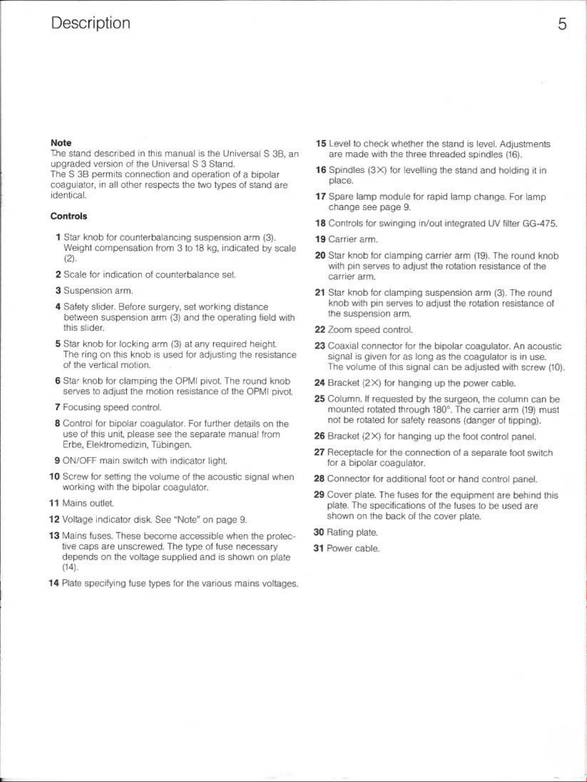
Description
Note
The stand
upgraded
‘The S 3B
coagulator,
identical
Controls
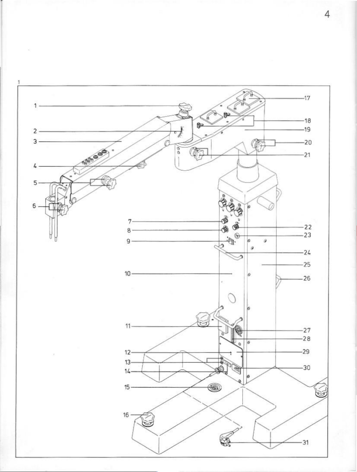
1
Star
Weight
2
Scale
3
Suspension
4
Safety
between
this
5
Star
The
of
6
Star
serves
7
Focusing
8
Control
use
Erbe,
9
ON/OFF
10
Screw
working
41
Mains
12
Voltage
13
Mains
tive
depends
(14).
14
Plate
described
version
permits
in
all
other
knob
for
counterbalancing
compensation
©,
for
indication
arm.
slider.
Before
suspension
slider.
knob
for
locking
ring
on
this
the
vertical
knob
of
this
motion.
for
clamping
to
adjust
speed
for
bipolar
unit
Elektromedizin,
main
switch
for
setting
with
the
outlet,
indicator
fuses.
These
caps
are
unscrewed.
on
the
specifying
in
this
manual
of
the
Universal
connection
respects
from 3 to
of
counterbalance
surgery,
arm
arm
knob
is
used
the
the
motion
control
coagulator.
please
see
S 3 Stand.
and
operation
the
set
(3)
and
(3)
at
for
OPMI
resistance
For
the
separate
Tubingen.
with
indicator
the
volume
bipolar
disk.
become
voltage
fuse
types
of
the
coagulator.
See
"Note"
accessible
The
type
supplied
for
the
is
the
Universal S 38,
of a bipolar
two
types
of
stand
suspension
18 ka,
working
the
any
required
adjusting
pivot.
further details
light,
acoustic
on
of
and
various
arm
(3).
indicated
set.
operating
by
distance
field
height.
the
resistance
The
round
of
the
OPMI
on
manual
page
when
fuse
is
shown
from
signal
9.
the
necessary
on
mains
voltages.
an
are
scale
with
knob
pivot
24
25
the
26
27
when
28
29
protec-
plate
30
31
15
Level
10
check
are
made
116
Spindles
place.
17
Spare
change
18
Controls
19
Carrier
20
Star
with
carrier
21
Star
knob
the
22
Zoom
23
Coaxial
signal
The
Bracket
Column.
mounted
not
Bracket
Receptacle
for a
Connector
Cover
plate,
shown
Rating
Power
(3%)
lamp
see
for
arm,
knob
pin
serves
arm,
knob
with
suspension
speed
connector
is
given
volume
(2X)
if
rotated
be
rotated
(2X)
bipolar
plate.
The
specifications
on
the
plate.
cable.
whether
with
the
for
module
page
swinging
for
clamping
to
for
clamping
pin
serves
the
three
threaded
levelling
for
rapid
9.
in/out
carrier
adjust
the
suspension
to
adjust
arm.
control.
for
the
bipolar
for
as
long
as
of
this
signal
can
for
hanging
requested
through
for
safety
for
hanging
for
the
connection
coagulator.
for
additional
The
fuses
up
by
the
180°.
reasons
up
foot
for
the
of
back
of
the
cover
stand
is
level.
Adjustments
spindles
the
stand
and holding
lamp
change.
integrated
arm
rotation
the
the
be
the
surgeon,
The
the
of a separate
or
hand
equipment
the
fuses
UV
(19).
The
resistance
arm
(3).
rotation
coagulator.
coaguiator
adjusted
power
cable.
the
column
carrier
(danger
foot
of
control
control
are
to
be
plate.
(16).
it
in
For
lamp
filter
GG-475.
round
knob
of
the
The
round
resistance
An
is
with
arm
tipping).
panel,
foot
panel.
behind
used
of
acoustic
in
use.
screw
(10).
can
be
(19)
must
switch
this
are
Page 5

|
|
1
Lamp
This
controlled
“F
3%"
2
Thermal
overheats
cause
button
slide-in
module
or * 4
of
in
module
supplies
with
knob
Fº
for
cutout
for
module
the
power
overheating
again.
fiber
O
in
carrier
fiber
optic
(6).
Selector
optic
illumination.
(1). I he
supply
is
interrupted.
before
pressing
arm
marked
cable
(18).
(7)
must
lamp
the
with
red
dot.
Brighiness
be
in
slide-in
Eliminate
thermal
is
position
module
the
cutout
3
Lamp
slide-in
This
module
controlled
“Fat”
4
Thermal
supplies
with
or" 4 Fº
cutout
module
knob
(8).
for
fiber
for
module
in
fiber
Selector
carrier
arm
marked
optic
cable
(19).
(9)
must
optic
illumination.
(3).
See
point
2.
J
with
blue
dot.
Brightness
be
in
is
position
Page 6

5
Knob
marked
adjust
the
6
Knob
marked
ness
of
nation
depending
7
Illumination-type
bulb
illumination,
with
output
with
the
fiber
yellow
voltage
red
dot.
optic
illumination
on
the
selector
Use
screwdriver
required,
Position
Position
Position
Position
8
Knob
ness
nation
8
Ilumination-type
bulb
required
Position
Position
Position H 3%
Position
10
Halogen
mode
Position H X£:
Position
F
#:
fiber
op
(red
dot).
<&
F:
fiber
optc
with a hand
H
k:
halogen
of
jacks
(16).
<&
H:
halogen
on/off
with a hand
marked
of
depending
the
fiber
with
blue
optic
on
illumination
the
selector
illumination.
F
#:
4
Use
fiber
(blue
F:
fiber
screwdriver
optic
dot)
optic
with a hand
halogen
of
<
H:
halogen
on/off
bulb
illumination
desired.
halogen
pair
<4
H:
halogen
on/off
bulb
jacks
(14)
bulb
with a hand
bull
of
jacks
bulb
with a hand
dot.
This
rotary
knob
serves
for
the
pair
of
yellow
jacks
This
knob
controls
or
halogen
position
for
illumination
illumination
bulb
bulb
dot,
position
for
illumination
illumination
af
selector
setting
fiber
fo
set
via
is
or
foot
control
illumination
illumination
or
foot
This
knob
controls
or
halogen
of
selector
setting
or
fiber
to
set
via
is
foot
control
illumination
illumination
or
foot
control,
Use
screwdriver
illumination
(15)
illumination
or
foot
the
bulb
(7)
optic
or
illumination
cable
(18)
switched
panel.
va
the
red
is
switched
control
optic
illumination
cable
switched
via
is
control
via
is
contro!
panel
the
bulb
(9).
or
(19)
panel.
the
blue
switched
panel
the
yellow
switched
panel.
to
11
(15)
112
bright-
illumi-
halogen
13
Notes
‘The
to
modification
These
operating
on/ott
14
pair
15
bright-
ilumi-
halogen
on/off
pair
to
set
16
17
18
19
Outlet
for
surgical
Outlet
for
X-Y
Outlet
for
operating
on
(14),
output
vollages
0-6
W/50 W or
must
jacks
also
on
alternating
Pair
of
blue
this
pair
of
jacks.
or!
GH
Pair
of
yellow
of
this
pair
of
Pair
of
red
this
pair
of
jacks.
or EH
Holder
the
Fiber
dot.
with
Fiber
dot
with
*
pin.
microscope
optic
cable
lts
light
knob
(6).
1.4
Fº
for
fiber
optic
cable
ls light
knob
(8).
46
Fº
for
fiber
sit
illuminator
coupling
microscope
(15)
ang
(16)
of
these
0-12
V/100 W on
be
made
permit
connection
current
jacks.
Knob
Selector
jacks.
Knob
jacks.
jacks.
Knob
Selector
This
pin
must
pivot
or
on
suspension
source
source
is
module
Selector
Selector
(7)
optic
illumination
on
suspension
is
module
(9)
optic
illumination.
or
with
automatic
or
pairs
of
jacks
request.
by
our
service
of
(8)
controls
(9)
must
(5)
controls
(6)
controls
(7)
must
audibly
the
engage
focusing
arm
(1).
Brightness
must
be
arm
(3).
Brightness
must
be
focusing
focusing
coupling.
re-centering.
coupling.
can
be
factory-set
Any
subsequent
technicians.
outside
be
the
be
in
in
equipment
the
output
voltage
in
position
the
output
output
in
position
in
coupling.
marked
position
marked
position
“He”
voltage
voltage
“H
the
groove
with
red
is
controlled
*F
3"
with
blue
is
controlled
“FX”
3"
or
or
of
of
of
Page 7

Operation
Note
The
stand
is
adjusted
However,
the
3
this
should
voltage
set
at
in
the
be
checked
window
(23)
factory
to
in
any
the
customer's
case
voltage.
by
reading
Ifthe
off
one
necessary.
voltages
of
our
do
service
not
correspond
technicians
the
and
fuse
unit
must
(24)
be
reset
by
changed,
i
Page 8

‘©
Connect
this,
‘©
Bring
three
©
Slacken
motion)
©
Slacken
working
scope
Check:
position
©
Adjust
with
ring
resistance
©
necessary,
suspension
knobs
for
©
Make
OPMI
see
operating
stand
spindles
star
into
star
position.
and
raise
set.
resistance
equipment
(3)
and
desired
(5)
and
locking.
power
equipment
manual
into
location
(22).
knob
(4)
equilibrium
knob
(2)
Push
retighten
OPMI
of
over
turn ring
has
set
motion
arm
(1)
(15).
connection.
and
of
your
required.
Check
(25)
and
bring
with
knob
and
bring
safety
slider
star
knob
and
lower
onto
the
vertical
14
kg).
For
into
the + direction
been
set.
resistance
and
of
carrier
Star
knobs
accessories
operation
Lock
whether
suspension
(13).
OPMI
towards
(2)
the
motion
this,
Retighten
of
arm
(6)
and
needed.
microscope.
in
position
stand
is
level.
arm
into
the
lowest
the
micro-
lowest
working
with
ring
(3)
slacken
the
grub
until
grub
OPMI
(17)
with
(16)
are
the
screw.
pivot,
round
only
(vertical
motion
For
with
the
(only
screw
in
used
Lamp
change
Ifa
halogen
module
the
halogen
For
©
© Pull
©
with
spare
lamp.
changing
Switch
lamp
and
socket
Insert
‘engages
module
off
to
out
remove
(1).
new halogen
(Fig.
4)
lamp
tails
during
the
detective
module
cool.
slido-in
and
(3),
the
lamp
instrument,
module
lamp.
Do
not
the
recess
put
stand
lamp
which
proceed
pull
with
When
removing
pull
the
cable.
lamp.
provided
back
operation,
should
is
equipped
as
out
mains
defective
Note
for
into
the
be
changed
with a new
follows:
plug
halogen
the
lamp
that
centring
it.
Replace
operation.
slide-in
for
and
allow
bulb
hold
the
lug
(2)
slide-in
Switching
©
Switch
©
Sot
Position F #£ : fiber
Position.<@F:
on
on
main
switch
selector
(8),
(9)
(blue
fiber
with a hand
Position H ++:
halogen
blue,
Position
‘©
Only
SH:
with
fiber
halogen
with a hand
optic
(4).
Operation
©
Bring
OPMI
into
working
©
Switch
on
and
—
avoid
(7)
red
knob
illumination
(18)
yellow
yellow
jacks;
(19)
blue
illumination
©
Set
focusing
© Set
zoom
Set
power
adjust
overloading:
for
fiber
via
the
knob
for
knob
for
via
the
speed
speed
with
for
bipolar
(12).
or
(20).
Key
to
symbols:
optic
illumination
or
red
optic
pair
fiber
pair
dot).
illumination
or
foot
bulb
illumination
yellow
or
red
bulb
illumination
or
foot
illumination:
position.
illumination
optic
bundle
of
red
illumination
optic
bundle
of
blue
with
knob
knob
(21)
coagulator
via
is
control
jacks.
control
swing
with
marked
jacks;
through
marked
jacks
(10)
with
(11)
fiber
optic
switched
panel
via
the
is
switched
panel.
in
filter
(7),
(18)
red
the
pair
blue
cable
on/off
pair
with
control
and
(19)
or
for
of
or
of
on/off
for
Page 9

10
Page 10

Page 11

Modules
Parts
of
the
stand
1
Power
column S 3B
or
power
2
Articulated
3Base
4
5
6
7
8
column S 3
suspension
Mono F illumination
or
Dual F illumination
or
Lid
for F lamp
Halogen
FC
cable 2 m
compartment
bulb
12
V/100
or
FC
cable
22
m
arm
W
30
Specifications
Order
No.
Stand
with
304903-9901
Base
304913-9901
304926
304932-9901
304951
Width
Depth
Carrier
Length
304952
304951-9030
380079-9040
303481-8103
Swing
Suspension
Length
Travel
Swing
303481-8104
Weight
height
extension
arm
angle
arm
angle
compensation
1
1685
mm
1825
mm
820
mm
870
mm
400
mm
210°
825
mm
722
mm
ES
3-18
kg
‘Supplementary
9
Magnetic
10
Column
11
Flash
supply
12
Tray
parts
holder
for
FC
extension
Couplings
13
Coupling
14
Focusing
15
Coupling
46
XY
17
Cardan
18
X-Y
Note;
microscopes
(dual
Hand
19
Four-way
20
Hand
24
Foot
22
Foot
23
Foot
Spares
1
set
of
1
set
of
1
set
of
2
coupling
K
120/76
with
coupling
coupling
Cardan
and
switch
panel
panel
fuses
fuses
fuses
coupling
items
17
and
18
from
our
observation).
foot
control
focusing/zoom
panel
with
EX
with 8 functions
with
for
220
for
110
for
panels
14
functions
for
bipolar
14
functions
V
V
120 V (UL)
are
OPMI 6 “D”
cable
gear
adjustment
only
suitable
series
switch
coagulator
304951-9031
304921-9130
304970
304971
304960
304962
305336
305343
304964
304965
for
operation
304998
304995-9901
304996
304981
304990-9902
304988
304989
304987
Total
weight
with
stabilizers
Electrical
Acc.
SEV,
Power
100-110-120-127-220-240
or
120
Max,
without
Stand
Stand S 38
Max.
Stand S 3
Stand S 38
Integrated
On
12
VINDO W halogen
modules
versions
to
DIN
IEC
601
UL
544
requirements
V,
50-60
Hz
(cps)
power
consumption
accessory
S 3
power
connected
consumption
fiber
optic
request
for 1 or 2 fiber
Part
1/VDE
0750
Part
V,
50-80
to
using
Hz
integrated
integrated
illumination
reflector
lamps
apto
cables,
on
UV
request)
1
spare
lamp
module
Outlet
1X6
W/50
W,
convertible
2X12
V/100 W adjustable,
over
to
integrated
surgical
Adjustable
coaguiator.
slit
illuminator
zoom
and
to
12
each
fiber
optic
or
motorized
focusing
V/100
W,
can
be
illumination,
focusing
speeds,
98
kg
182
kg
1/05/82
(cps)
power
outlet:
600
VA
700 VA
power
outlet:
1500
VA
1600
VA
quick-change
filter
(green
adjustable;
individually
X-Y
coupling,
coupling.
power
outlet,
slide-in
fiter
on
switched
bipolar
Bipolar
Power
Rated
coagulator
consumption
frequency
50
Wat
75
600-1000
Ohm
kHz
 Loading...