

Page 1
2722
2742
3742
Desktop
Thermal Printer
User’s Manual
User’s Manual No. 980344-001 Rev. A
©2001 Zebra Technologies Corporation
Page 2
COPYRIGHT NOTICE
This document contains information proprietary to Zebra Technologies Corporation. This docu
mentandtheinformationcontainedwithiniscopyrightedbyZebraTechnologiesCorporation and
maynotbeduplicatedinfullorinpartbyanypersonwithoutwrittenapproval from Zebra Technol
ogiesCorporation.Whileeveryefforthasbeen made to keep the information contained withincur
rentand accurate asof the dateof publication, noguarantee is givenor implied thatthe document
is error-free or that itis accuratewith regard to any specification. Zebra Technologies Corporation
reserves the right to make changes, for the purpose of product improvement, at any time.
TRADEMARKS
LP2722, TLP2722, LP2742, TLP2742 and TLP3742 are service marks and Zebra is atrademark
of ZebraTechnologiesCorporation.WindowsandMS-DOSareregisteredtrademarksofMicrosoft
Corp. All other marks are trademarks or registered trademarks of their respective holders.
LP2722, TLP2722, LP2742, TLP2742 and TLP3742 Thermal Printers
-
-
-
European Council
Directive
89/336/EEC EMC Directive EN55022-A 1995 RF Emissions control
92/31/EE EMC Directive EN50082-1 1992
Compliance to Standards
Immunity to Electromag-
netic Disturbances
FCC - DECLARATION OF CONFORMITY:
Models: LP2722, TLP2722, LP2742, TLP2742 and TLP3742 conform to
the following specification:
FCCPart15, Subpart B, Section15.107(a)andSection 15.109(a) Class Bdigitaldevice
Supplemental Information:
Thisdevicecomplieswith Part 15 of theFCCRules.Operationis subject to the followingTwoCon
ditions: (1) This device may not cause harmful interference , and (2) this device must accept any
interference received, including interference that may cause undesired operation.
Industry Canada Notice:
This device complies with Industry Canada ICS-003 class B requirements.
Cet equipement est conforme a l’ICS-003 classe B de la norm Industrielle Canadian
-
ii 980344-001 Rev.A
Page 3

TABLE OF CONTENTS
Installation and Operation
Unpacking Your Printer . . . . . . . . . . . . . . . . . . . . 2
Getting To Know Your Printer . . . . . . . . . . . . . . . . . 3
Installation . . . . . . . . . . . . . . . . . . . . . . . . . . . 4
Attach Power . . . . . . . . . . . . . . . . . . . . . . . . . 4
Attach Interface Cable . . . . . . . . . . . . . . . . . . . . . 5
Load Media . . . . . . . . . . . . . . . . . . . . . . . . . . 6
Before You Load Media in the Printer . . . . . . . . . . . . . 7
AutoSense . . . . . . . . . . . . . . . . . . . . . . . . . . . 13
Install Software . . . . . . . . . . . . . . . . . . . . . . . . 13
Using Fan-Fold Media . . . . . . . . . . . . . . . . . . . . . 14
Label Dispenser . . . . . . . . . . . . . . . . . . . . . . . . 15
Thermal Transfer Ribbon Loading . . . . . . . . . . . . . . . 18
Appendix A - Troubleshooting . . . . . . . . . . . . . . . . 21
Printer Maintenance . . . . . . . . . . . . . . . . . . . . . . 22
Printer Configuration Settings . . . . . . . . . . . . . . . . . 23
Serial Interface Communication Configuration. . . . . . . . . 24
RS-232 Serial Interface Cable Wiring . . . . . . . . . . . . . 24
Parallel Interface Cable Wiring. . . . . . . . . . . . . . . . . 25
980344-001 Rev.A iii
Page 4
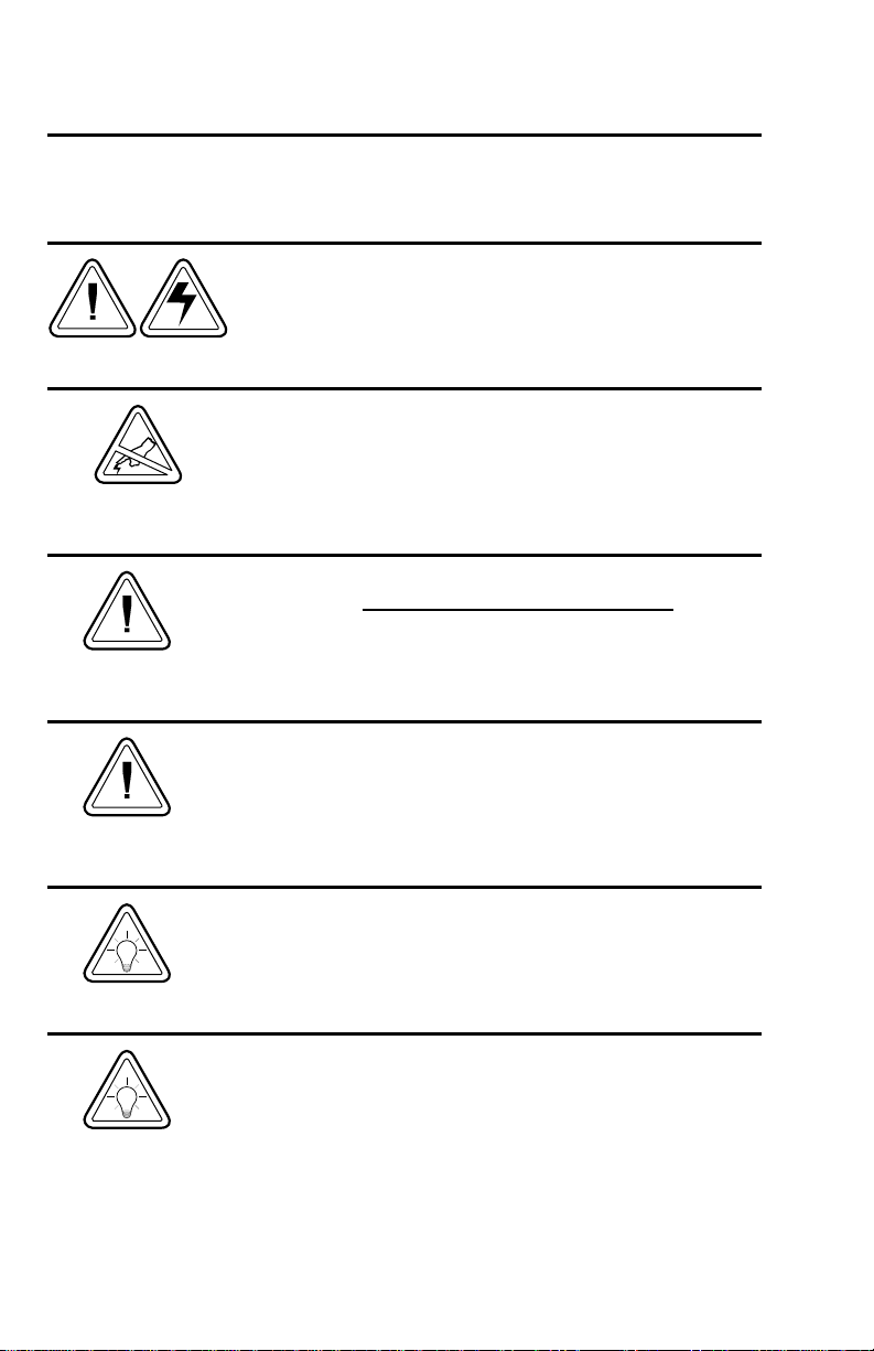
General Cautions and Warnings
This page describes general safety and maintenance warnings and cautions for the printer and
are referenced throughout the manual.
Warning - Shock Hazard
The printer should never be operated in a location where it can
get wet. Personal injury could result.
Warning - Static Discharge
The discharge of electrostatic energy that accumulates on the
surface of the human body or other surfaces can damage or
destroy the print head or electronic components used in this
device. DO NOT TOUCH the print head or the electronic
components under the print head assembly.
Caution - Printer Setup & Handling
1)When installing or modifying the printer setup or
configuration, ALWAYS TURN POWER OFF Before
A) Connecting any cables.
B) Performing any cleaning or maintenance operations.
C) Moving the printer.
:
Media Warning
Always use high quality approved labels and tags. If adhesive
backed labels are used that DO NOT lay flat on the backing
liner, the exposed edges may stick to the label guides and
rollers inside the printer, causing the label to peel off from the
liner and jam the printer.
Media Reload Hint
If you should run out of labels while printing, DO NOT turn the
power switch OFF (0) while reloading or data loss may occur.
Theprinter will automaticallyresume printing whena new label
or ribbon roll is loaded.
Print Quality Tip
Print density (darkness) is affected by the heat energy (density
setting) applied and by the print speed. Changing both Print
Speed and Density may be required to achieve the desired
results.
iv 980344-001 Rev.A
Page 5

Installation and Operation
1
Installation and Operation
This section provides information on the installation and operation of the printer.
The printer is a low cost, desktop thermal bar
codeprinter.LPmodels aredirectthermal. TLP
modes are thermal transfer and direct thermal
printers.Thisfamily of printersisspecifically designedfor printing labels, tags or continuous receipts (with or without bar codes) from a
DOS™, Windows™or ASCII-based compatible
computer.
980344-001 Rev.A 1
Page 6
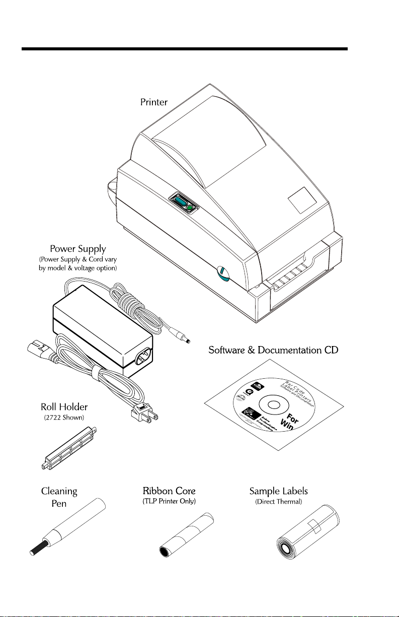
Installation and Operation
Unpacking Your Printer
B
a
L
r
a
S
C
o
b
ftw
e
o
a
l P
re
d
a
e
n
r
d
in
D
o
t
c
e
u
m
r
s
e
n
ta
tio
©
2001 Zeb
ra T
echno
105551
log
-006
ie
W
s Co
rporation
n
For
in
2 980344-001 Rev.A
Page 7
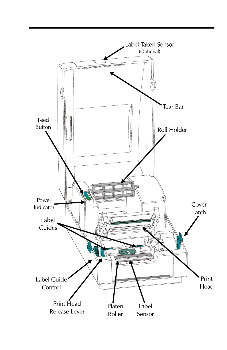
Getting To Know Your Printer
Installation and Operation
980344-001 Rev.A 3
Page 8
Installation and Operation
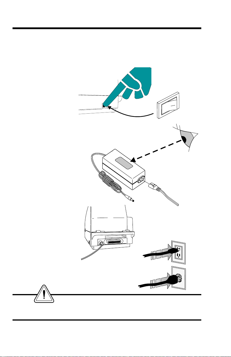
Installation The following steps will guide you through the
installation of the printer, media and software.
Step 1 - Attach Power
Power OFF
O
Check Power
Module Voltage
Plug Into
Power Module
XXXXXXXXXXXXXX
XXXXXXXX XXXXXXXXX
SHOCK HAZARD WARNING
See page iv
4 980344-001 Rev.A
Page 9
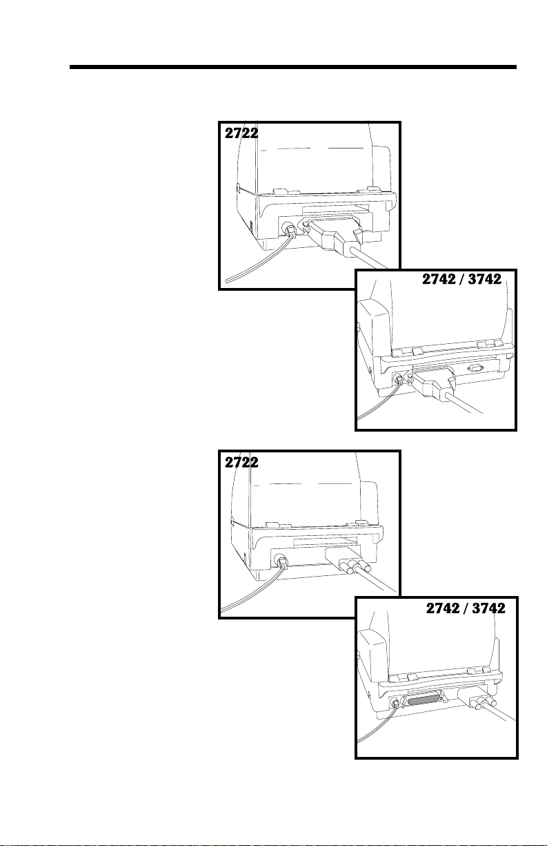
Step 2 - Attach Interface Cable
Parallel Interface
Installation and Operation
Serial Interface
980344-001 Rev.A 5
Page 10

Installation and Operation
Step 3 - Load Media
Open Cover
MOVIE
Open Print Head
MOVIE
Open Guides
MOVIE
6 980344-001 Rev.A
Page 11

Installation and Operation
Before You Load
Media in the
Printer
Labels
Remove all labels
that are held by
adhesives or tape
MOVIE
Tag Stock
You must remove the outside length of media
(that is, one, full revolution of labels and any
liner). When youremovethis part ofthemedia,
you remove the oils, dust, and adhesives that
contaminate it. Tape or adhesive holds the
loose end and the outside length of media
becomes contaminated when handled or
stored.
Detach both ends of
the bottom tag
You must avoid dragging adhesive or dirty
mediabetween theprintheadandplaten. Such
an occurrence damages the print head and is
not covered under your warranty. Using clean
media prevents damage and reduces wear on
the print head and platen.
980344-001 Rev.A 7
Page 12

Installation and Operation
Step 3 - Load Media (cont.)
Media
2722
Install Roll
2742 / 3742
Install Roll
OUT
OUT
OUT
OUT
MOVIE
OUT
OUT
OUT
OUT
8 980344-001 Rev.A
Page 13

Step 3 - Load Media (cont.)
Thread the Media
MOVIE
Installation and Operation
Seat Media Roll
MOVIE
980344-001 Rev.A 9
Page 14

Installation and Operation
Step 3 - Load Media (cont.)
Close Guides
Close Guides
2742 / 3742
MOVIE
10 980344-001 Rev.A
Page 15

Step 3 - Load Media (cont.)
Close Print Head
MOVIE
Installation and Operation
Close Cover
MOVIE
980344-001 Rev.A 11
Page 16

Installation and Operation
Step 3 - Load Media (cont.)
Power ON
If the indicator fails to light, refer to
Appendix A - Trouble Shooting.
Press FEED Button
O
Run the AutoSense routine.
12 980344-001 Rev.A
Page 17

Step 4 - AutoSense
Installation and Operation
MOVIE
Power OFF
Press & Hold
FEED Button
Power ON
Release FEED Button
Print Status
(Dump Mode Printout)
Press FEED Button
Step 5 - Install Software
OFF HOLD
ON
Sample: DUMP Mode
Printout
2 UKQ1813 4.00
Serial port : 96,N,8,1
Image buffer size:245K
Fmem:000,0K,019.9K avl
Gmem:000K,0241K avl
E
mem:000K,0241K avl
I8,0,001 rY
S8 D12 R032,000 ZT UN
q0450 Q0800,034
Option:D
11 12 13
now in DUMP
O
RELEASE
O
PRESS
Computer ON
Insert Printer
CD ROM
Start your computer and follow the installation
instructions on the compact disc (CD).
980344-001 Rev.A 13
Page 18

Installation and Operation
Using Fan-Fold Media
Place Media In Rear
Face Print
Surface UP
Insert & Load
Media
14 980344-001 Rev.A
Page 19

Installation and Operation
Label Dispenser Printers with an optional label taken sensor can
dispenseasinglepeeledlabel.Removethelabel
to automatically print the next label.
MOVIE
15CM of Labels
Exposed Labels
Exposed Liner
Expose
(2722 Shown)
Peel
Cut End of
(2722 Shown)
Pull Print Head
Release Lever
(2722 Shown)
Insert Liner
Under Peel Bar
980344-001 Rev.A 15
Page 20

Installation and Operation
Label Dispense Option
Insert Liner
(2742 Shown)
Pull Liner Through
(2742 Shown)
TLP2722
16 980344-001 Rev.A
Page 21

Label Dispense Option
Close Print Head
Close Cover
Push to Open
Label Taken Sensor
Installation and Operation
Press FEED Button
TLP2722
Remove Presented
Label
TLP2722
980344-001 Rev.A 17
Page 22

Installation and Operation
Thermal Transfer Ribbon Loading
This feature is supported on TLP model
printers, only.
MOVIE
Thermal Transfer
Print Head
Mechanism
Ribbon Path
18 980344-001 Rev.A
Page 23

Thermal Transfer Ribbon Loading
Open Print Head
Load Ribbon Core
Load Transfer Ribbon
Start Ribbon
Open Print Head
(Rear View)
Pull Ribbon Around
Print Head
Installation and Operation
Close
980344-001 Rev.A 19
Page 24

Installation and Operation
20 980344-001 Rev.A
Page 25

Appendix A - Troubleshooting
Problem Solution or Reason
POWER indicator does not
light GREEN when power
switch is turned to ON (1)
position.
1. Check power connections from A.C.
outlet to power supply to printer.
POWER indicator lights
GREEN, but printer will not
print.
Printer appears to be
working (media is being fed
out), but nothing is printed.
Printing is faded or poor
quality.
Prints only partial label or
skips a label.
Printing stops and POWER
indicator lights ORANGE or
RED.
1. Check interface cable connections from
computer to printer.
1. Verify that the labels are the correct
type (direct thermal).
2. Check that the roll is loaded with the di
rect thermal side facing up.
3. Clean the print head with cleaning pen.
4. For TLP models, check that the ribbon is
properly installed.
1. Clean the print head with cleaning pen.
2. Adjust print speed/darkness in software.
1. Perform AutoSense gap sensor
adjustment on page 13.
2. Label caught on print head.
3. Print head is not properly latched.
4. Possible software problem. Check the
printer memory configuration. Refer to
the EPL2 Programming manual.
1. Perform AutoSense gap sensor adjust
-
ment on page 13.
2. Possible problem with label stock. Use
only approved labels and tags.
3. Possible label jam.
4. Insufficient memory for label size. Check
the printer memory configuration.
5. Possible software problem. Refer to the
EPL2 Programming manual.
-
980344-001 Rev.A 21
Page 26

Printer
Maintenance
MOVIE
Clean the
Print Head
Don’t Clean Rollers
with Cleaning Pen
22 980344-001 Rev.A
Page 27

Printer
Configuration
Settings
The printer has flash (non-volatile) memory to
store printer configuration settings. Thesettings
are stored in flash memory and are set by
programing, printer drivers or the AutoSense
routine. The settings are shown on the Dump
mode printout or can be reported back to the
host via the serial port.
Thefollowingare the basic settings storedinthe
printer:
PrintMode-Direct(OD)orThermalTransfer(O)
Speed (S)
Density (D) or heat applied
Form (label) length and gap in dots (Q)
Form (label) width in dots (q)
Serial Port (Y)
Margin (R)
Buffer Mode (r)
Options: D
Print Mode is Direct Thermal (OD)
Dump Mode
Printout
(See the U command in
the Programmer’s manual
for details)
980344-001 Rev.A 23
Page 28

Serial Interface
Communication
Configuration
The printer’s serial port is configured with the
Ycommand forthe printer.Theprintersupports
interface data rates from 1200 to 38,400 baud.
See the programmer's manual for details.
Theprinter’sserial port defaultconfigurationis:
9600 baud
8 bit data
1 stop bit
No parity
RS-232 Serial
Interface Cable
Wiring
The figure below displays the cable wiring re
quired to use the printer’s serial interface.
DB-9
N/C
RxD
TxD
DTR
GND
DSR
RTS
CTS
RI
N/C
RxD
TxD
DTR
GND
DSR
RTS
CTS
RI
*+5 volts at 150 mA for external device (e.g. KDU or scanner)
Pin #
Female DB-9 to Male DB-9
DB-25
Pin #
Female DB-25 to Male DB-9
DB-9
Pin #
11
22
33
44
55
66
77
88
99
DB-9
Pin #
18
23
32
420
57
66
74
85
922
PrinterHost
+5 Volts*
TxD
RxD
N/C
GND
RDY
N/C
RDY
N/C
PrinterHost
+5 Volts*
TxD
RxD
N/C
GND
RDY
N/C
RDY
N/C
-
24
980344-001 Rev.A
Page 29

Parallel Interface
Cable Wiring
The figure below displays the cable wiring
required to use the printer's Centronics parallel
interface.
HOST
STROBE
DATA 0
DATA 1
DATA 2
DATA 3
DATA 4
DATA 5
DATA 6
DATA 7
ACK/
BUSY
PAPER ERR.
READY
INIT
ERROR/
N/A
N/A
N/A
SIG. GND
SIG. GND
SIG. GND
SIG. GND
SIG. GND
SIG. GND
SIG. GND
DB-25
Pin No.
1
2
3
4
5
6
7
8
9
10
11
12
13
14
15
16
17
18
19
20
21
22
23
24
25
Centronics
Pin No.
Female DB-25 to Male Centronics
(Cable)
1
2
3
4
5
6
7
8
9
10
11
12
13
14
15
16
17
18
19
20
21
22
23
24
25
PRINTER
STROBE
DATA 0
DATA 1
DATA 2
DATA 3
DATA 4
DATA 5
DATA 6
DATA 7
ACK/
BUSY
PAPER ERR.
READY
INIT
ERROR/
N/A
N/A
+5V
SIG. GND
SIG. GND
SIG. GND
SIG. GND
SIG. GND
SIG. GND
980344-001 Rev.A
+5 volts at 300 mA for external device (e.g. PrintServer)
25
Page 30

26 980344-001 Rev.A
 Loading...