

Page 1
UMAN-RW4-003 Rev. A
March, 2005
Page 2

Page 3

Contents
Proprietary Statement ....................................... 5
Introduction to the RW 420 ............................... 7
Unpacking and Inspection ................................................... 7
Reporting Damage ............................................................... 7
Getting Ready to Print ....................................... 9
Battery .................................................................................. 9
Battery Safety ............................................................................... 9
Installing the Battery ....................................................................
Charging the Battery ....................................................................
Model LI 72 Single Battery Charger ........................................... 9
Model UCLI72-4 Quad Charger .................................................10
Charger Safety ...................................................................................... 10
Loading the Media ............................................................. 12
Loading Media in the RW 420 Printer ....................................... 12
Loading Media From An Internal Supply .................................13
Loading Media From An External Supply ............................... 14
Operator Controls .............................................................. 16
Control Panel .............................................................................. 16
Verify the Printer Is Working .............................................. 20
Printing a Configuration Label ..................................................20
Connecting the Printer .................................... 21
Cable Communications ..................................................... 21
Serial (RS232C) .......................................................................... 21
USB ............................................................................................
Wireless Communications ................................................. 23
Wireless Communications with Bluetooth® ............................ 23
Wireless Local Area Network Module Using CF Radio ...........
Wireless Local Area Network Overview .................................. 27
Setting Up the Software ............................................................ 27
Card Reader Options ........................................
Magnetic Stripe Reader ..................................................... 29
Smart Card Reader ............................................................ 31
Using the Accessories ...................................... 32
Belt Clip ....................................................................................... 32
Adjustable Shoulder Strap ........................................................
Cradle ..........................................................................................
Installing The Printer In The Cradle ..................................................... 34
Removing The Printer From The Crad
Preventive Maintenance .................................. 37
Extending Battery Life ........................................................ 37
Cleaning Instructions ......................................................... 37
Troubleshooting .............................................. 39
LCD Control Panel Indicators ............................................. 39
Troubleshooting Topics ..................................................... 40
le .............................................. 36
9
9
22
25
29
33
34
3
RW 420 User Guide
Page 4

Troubleshooting Techniques ............................................. 42
Printing a Configuration Label ..................................................42
Performing a Forced Shutdown ................................................
Communications Diagnostics ................................................... 42
Calling Technical Support .........................................................
Specifications ..................................................
Printing Specifications ..............................................................
Memory/Communications Specifications ...............................47
Communications Ports ..............................................................
USB ....................................................................................................... 48
RS232 .................................................................................................... 48
Media Specifications .................................................................50
Font/Bar Code Specifications ................................................... 51
Physical/Environmental/Electrical Specifications ................... 52
RW 420 Accessories .................................................................
Appendix A- Interface Cables .................................
RS232 Download Cable ............................................................. 55
USB Cable ................................................................................... 55
More Interface Cables
..............................................................56
Appendix B- Media Supplies ..................................
Appendix C- Maintenance Supplies ..........................
Appendix D ...................................................... 58
Product Support .........................................................................
Battery Disposal ......................................................................... 59
Product Disposal ........................................................................ 59
Index ................................................................
Patent Numbers ...............................................
42
43
47
47
48
54
55
57
57
58
60
61
4
RW 420 User Guide
Page 5

Proprietary Statement
This manual contains proprietary information of Zebra Technologies Corporation. It is intended solely for the information and use of parties operating and maintaining the equipment
described herein. Such proprietary information may not be used, reproduced, or disclosed
to any other parties for any other purpose without the expressed written permission of Zebra
Technologies Corporation.
Product Improvements
Since continuous product improvement is a policy of Zebra Technologies Corporation, all
specifications and signs are subject to change without notice.
FCC Compliance Statement
Class B digital device. Tested to comply with FCC standards for home or office use.
WARNING: Exposure to Radio Frequency radiation. To conform to FCC RF exposure require
ments this device shall be used in accordance with the operating conditions and instructions
listed in this manual. Note that there are several radio options available with this printer. Addi
tional regulatory information is contained in later sections devoted to each radio individually.
NOTE: This unit was tested with shielded cables on the peripheral devices. Shielded cables
must be used with the unit to insure compliance.
Changes or modifications to this unit not expressly approved by Zebra Technologies Corpora
tion could void the user’s authority to operate this equipment.
Canadian Compliance Statement
This Class B digital apparatus complies with Canadian ICES-003.
Cet appareil numérique de la classe B est conforme á la norme NMB-003 du Canada.
“IC:” before the equipment certification number signifies that the Industry Canada technical
specifications were met. It does not guarantee that the certified product will operate to the
user’s satisfaction.
Agency Approvals and Regulatory Information
• Design certified by CSA • IP54 Certified
• FCC part 15 • Canadian STD RSS-210
• NOM/NYCE (Mexico) • EN60950: 2000 Safety Standard
• C-Tick (Australia) • EN55022:1998 Class B European
Electromagnetic Radiation Standard
Liability Disclaimer
Inasmuch as every effort has been made to supply accurate information in this manual, Zebra
Technologies Corporation is not liable for any erroneous information or omissions. Zebra
Technologies Corporation reserves the right to correct any such errors and disclaims liability
resulting therefrom.
No Liability for Consequential Damage
In no event shall Zebra Technologies Corporation or anyone else involved in the creation, production, or delivery of the accompanying product (including hardware and software) be liable
for any damages whatsoever (including, without limitation, damages for loss of business prof
its, business interruption, loss of business information, or other pecuniary loss) arising out of
the use of or the results of use of or inability to use such product, even if Zebra Technologies
Corporation has been advised of the possibility of such damages. Because some states do not
allow the exclusion of liability for consequential or incidental damages, the above limitation
may not apply to you.
Copyrights
The copyrights in this manual and the label print engine described therein are owned by Zebra
Technologies Corporation. Unauthorized reproduction of this manual or the software in the
label print engine may result in imprisonment of up to one year and fines of up to $10,000 (17
U.S.C.506). Copyright violators may be subject to civil liability.
This product may contain ZPL®, ZPL II®, and ZebraLinktm programs; Element Energy Equalizer®
Circuit; E3®; and AGFA fonts. Software © ZIH Corp. All rights reserved worldwide.
ZebraLink and all product names and numbers are trademarks, and Zebra, the Zebra logo, ZPL,
ZPL II, Element Energy Equalizer Circuit, and E3 Circuit are registered trademarks of ZIH Corp.
All rights reserved worldwide.
CG Triumvirate is a trademark of AGFA Monotype Corporation. All rights reserved worldwide.
CG Triumvirate
Corporation. All rights reserved worldwide. UFST is a registered trademark of AGFA Monotype
Corporation. All rights reserved worldwide.
All other brand names, product names, or trademarks belong to their respective holders.
©
2005 ZIH Corp.
tm
font © AGFA Monotype Corporation. Intellifont® portion © AGFA Monotype
5
RW 420 User Guide
-
-
-
-
Page 6
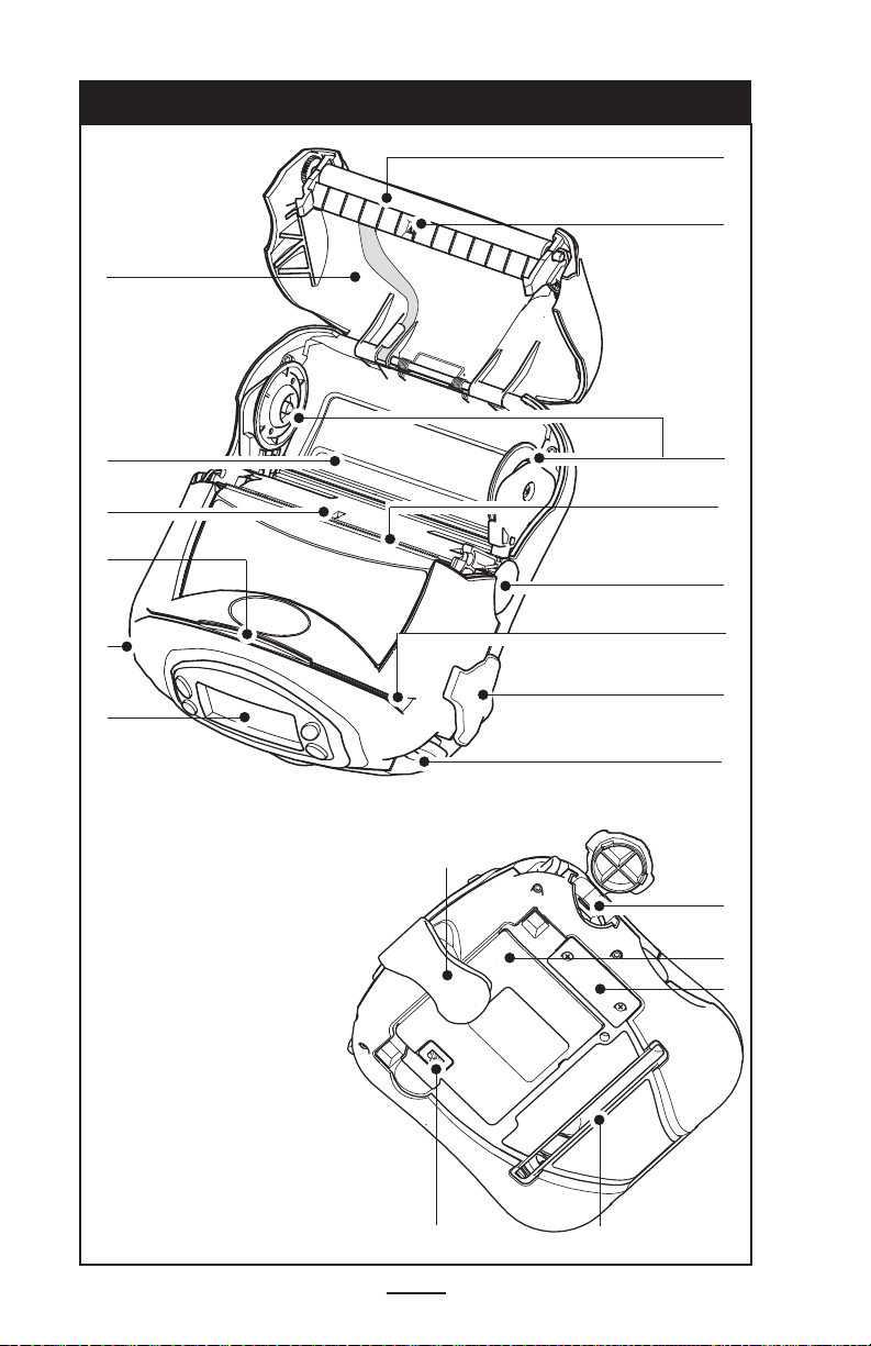
Figure 1: RW 420 Overview
13
1
2
12
11
10
8
9
1. Platen Roller
2. Bar Sensor
3. Media Support Disks
4. Printhead
5. Latch Release Button
6. Magnetic Stripe Reader
(MSR) Slot
7. Communications
Port Door
8. “D” Rings
9. Control Panel
10. Smart Card Slot
11. Gap Sensor
12. Bottom Media Feed Slot
(external media models only)
13. Media Cover
14. Belt Clip
15. Communications Port
16. Battery
17. Docking Connector Cove
18. Battery Charging Receptacle
18
3
4
5
6
7
8
14
15
16
17
12
6
RW 420 User Guide
Page 7

Introduction to the RW 420
Thank you for choosing our Zebra RW 420 Mobile Printer. It
is one of a series of rugged printers that are sure to become
productive and efficient additions to your workplace thanks to
their innovative design. Because the RW 420 is made by Zebra
Technologies, you’re assured of world-class support for all of
your bar code printers, software, and supplies.
• This User’s Guide gives you the information you’ll need to
operate and maintain your RW 420 printer.
• The RW 420 uses the CPCL programming language. To
create and print receipts and labels using the CPCL
language, refer to our Label Vista™ label creation pro
gram or the Mobile Printing Systems CPCL Programming Manual which is available on our Web site at:
http://www.zebra.com/manuals .
• The RW 420 includes interpreters for the ZPL II® programming language (up to Version 30.8.4) and the EPL programming language. Manuals for the ZPL and EPL label
design programming languages are available on our Web
site at: http://www.zebra.com/manuals.
Unpacking and Inspection
Inspect the printer for possible shipping damage:
• Check all exterior surfaces for damage.
• Open the media cover (refer to “Loading the Media” in
the Getting Ready to Print section) and inspect the media
compartment for damage.
In case return shipping is required, save the carton and all
packing material.
Reporting Damage
If you discover shipping damage:
• Immediately notify and file a damage report with the ship
ping company. Zebra Technologies Corporation is not
responsible for any damage incurred during shipment of
the printer and will not cover the repair of this damage
under its warranty policy.
• Keep the carton and all packing material for inspection.
• Notify your authorized Zebra re-seller.
-
7
RW 420 User Guide
Page 8
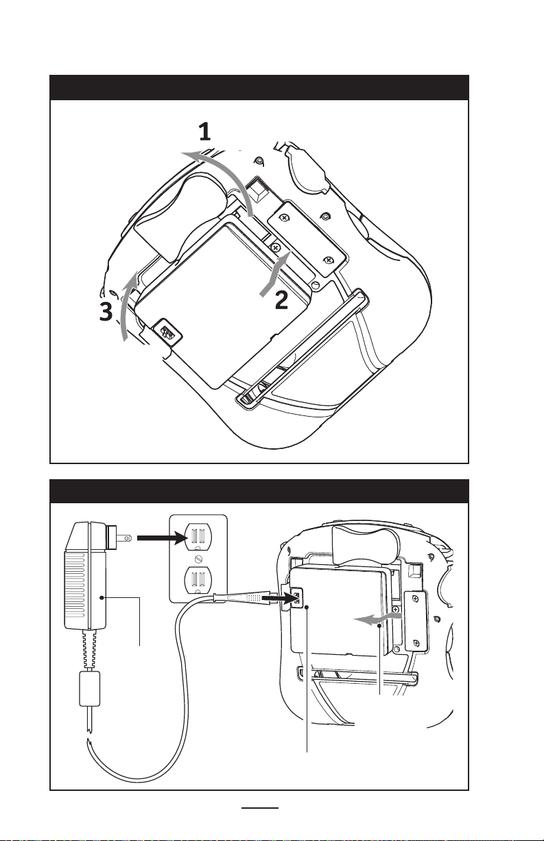
Figure 2: Installing the Battery
Rotate Belt Clip
out of the way.
Insert this end of
the Battery Pack
into the printer
Rock the Battery Pack
into the Printer until
the latch clicks into
place.
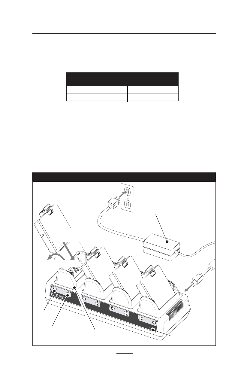
Figure 3: Single Charger
LI72 Charger
RW 420 User Guide
Charger Jack
8
For best
results,
remove
the Battery
Pack while
charging.
Page 9

Getting Ready to Print
Battery
Battery Safety
The Battery Packs used on Zebra Mobile Printers contain a
great deal of energy and can cause personal injury or start a
fire if used improperly or carelessly. Please observe the following safety practices:
Avoid accidental short circuiting of any battery. Allowing
battery terminals to contact conductive material will create
a short circuit which could cause burns and other injuries or
could start a fire.
Batteries can explode or catch fire if improperly charged
or exposed to high temperatures or fire.
Do not disassemble, crush or expose batteries to water.
CAUTION: Use of any charger not approved specifically by
Zebra for use with its batteries could cause damage to the
battery pack or the printer and will void the warranty.
Installing the Battery
NOTE: Batteries are shipped uncharged. Remove protective shrink-
wrap and labels from new battery packs prior to use.
1. Rotate the Belt Clip to allow access to the Battery compartment.
2. Insert the battery into the printer as shown in Figure 2,
3. Rock the Battery into the printer as shown until it locks in
place.
When the battery is first installed, the Control Panel indicators may briefly turn on and then go off, indicating the battery
is not fully charged (see “Charging the Battery” below and
“Operator Controls.”)
Charging the Battery
Model LI 72 Single Battery Charger
Refer to Figure 3. Your battery charger may look slightly different from the one illustrated.
1. Plug the Charger into the appropriate A.C. wall receptacle.
Then insert the charge cable into the battery charger jack.
2. The charger LED will indicate the status of the charger as
follows:
• A steady light indicates the battery is undergoing a fast
charge.
• A slow blinking light indicates the charger is in trickle
9
RW 420 User Guide
Page 10
mode. The battery is ready for use.
• A rapidly blinking light indicates a problem with the battery. The battery may have an internal short, or its charge
monitoring circuitry may be malfunctioning. The battery
should not be used any further.
NOTE: While the LI 72 Charger allows Battery Packs to be
charged when installed in the printer, best results are obtained
with the battery removed.
Do not attempt to print while charging batteries with the
LI 72 charger. Attempting to print while charging can result in
improperly charged batteries.
Model UCLI72-4 Quad Charger
Charger Safety
Use care in locating the Quad Charger. Do not place it in
locations where liquids or metallic objects may be dropped into
the charging bays. Do not block the ventilating slots on the top
and bottom covers. Ensure that the Charger is plugged into a
power source which won’t accidently be turned off if you will be
charging batteries overnight.
The UCLI72-4 Quad Charger is designed to charge up to four
RW Series battery packs simultaneously. Batteries must be
removed from the printer to be charged in the Quad Charger.
1. Ensure that the charger has been installed properly per
the Quad Charger instruction manual. Ensure that the power
indicator on the front panel is on.
2. Remove any protective shrink-wrap and labels from all
battery packs prior to use. Plug a battery pack into any one
of the four charging bays as shown in Figure 4, noting the
orientation of the battery pack. Slide the battery pack into the
charging bay until it stops. Then rock the battery pack back
until it snaps into place. The amber indicator directly under
the battery being charged will turn on if the battery is properly
inserted.
The indicators under the battery will allow you to monitor
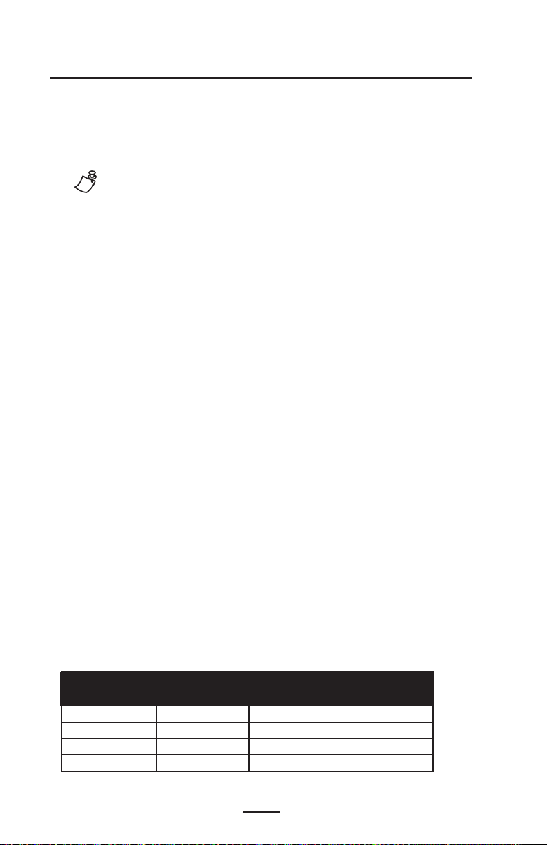
the charging process per the table below:
Battery Status Indicators
Amber LED Green LED Battery Status
On Off Charging
On Flashing 80% charged (O.K. to use)
Off On Completely Charged
Flashing Of f Fault
10
RW 420 User Guide
Page 11
Note: A fault condition is caused by a problem with the battery.
Fault
Fast Charge
Fault
Fast Charge
Fault
Fast Charge
Ready
Power
Full Charge
Ready
Full Charge
Ready
Full Charge
Full Charge
Fault
Fast Charge
Ready
The charger may indicate a fault because the battery is too
hot or cold to charge reliably. Try to charge the battery again
when it returns to the room’s ambient temperature. If the Amber
indicator starts flashing on the second attempt, the battery
should be discarded.
Quad Charger Cycle Times for RW 420
Battery Status Time
Battery 80% Charged 2.5 Hrs
Battery Fully Charged 5 Hrs.
NOTE: These times are for completely discharged batteries.
Partially discharged Battery Packs will take less time to
reach their charged state. Battery Packs which have reached
80% of their charge capacity may be used, however, it is recommended that you allow the batteries to reach a full charge
to maintain maximum battery life.
The UCLI72-4 Quad Charger’s safety features will stop
charging a battery after six hours regardless of its charge
state.
Figure 4: UCLI72-4 Quad Charger
Power Supply
2. Rock Battery Pack
into place
Amber
Indicator
1. Slide Battery Pack into
Charger Bay
Green
Indicator
Charger Bay
11
RW 420 User Guide
Power Indicator
Page 12
Loading the Media
The RW 420 printer is designed to print either continuous
(journal) media or label stock.
Loading Media in the RW 420 Printer
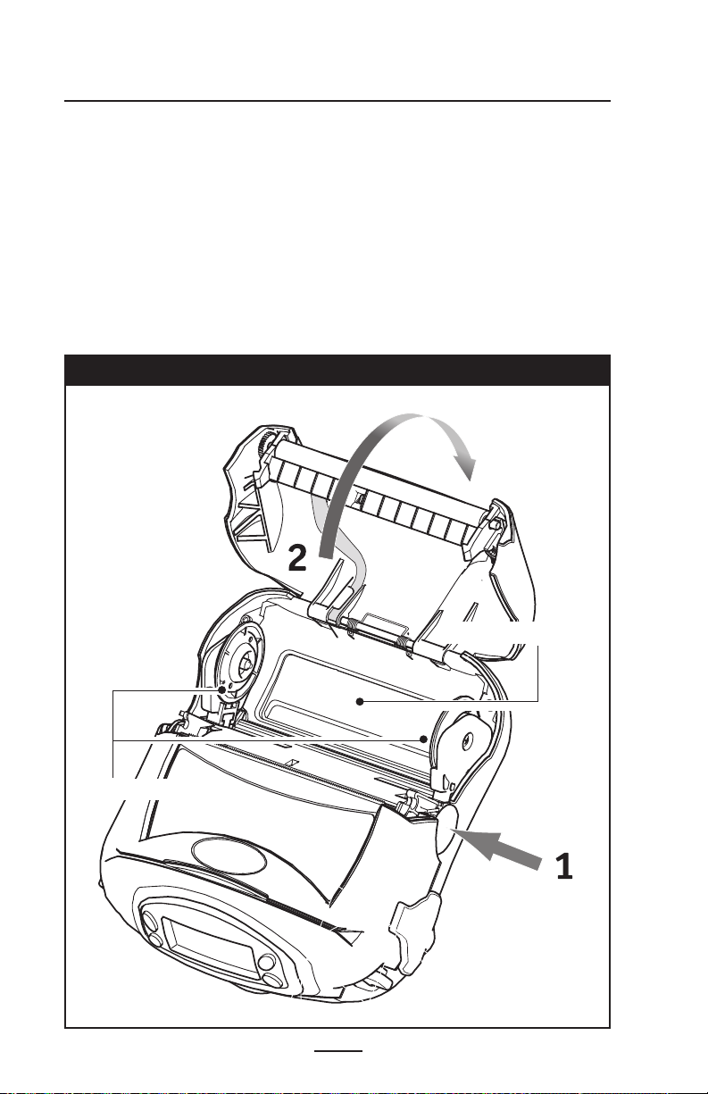
1. Open the printer: Refer to Figure 5.
• Press the latch release button on the side of the printer as
shown at “1” below. The media cover will open automatically
• Rotate the Media Cover back completely as shown at
“2”, exposing the media compartment and the adjustable
media supports.
Figure 5: Opening the Printer
Media Support
Disks
Media Compartment
12
RW 420 User Guide
Page 13
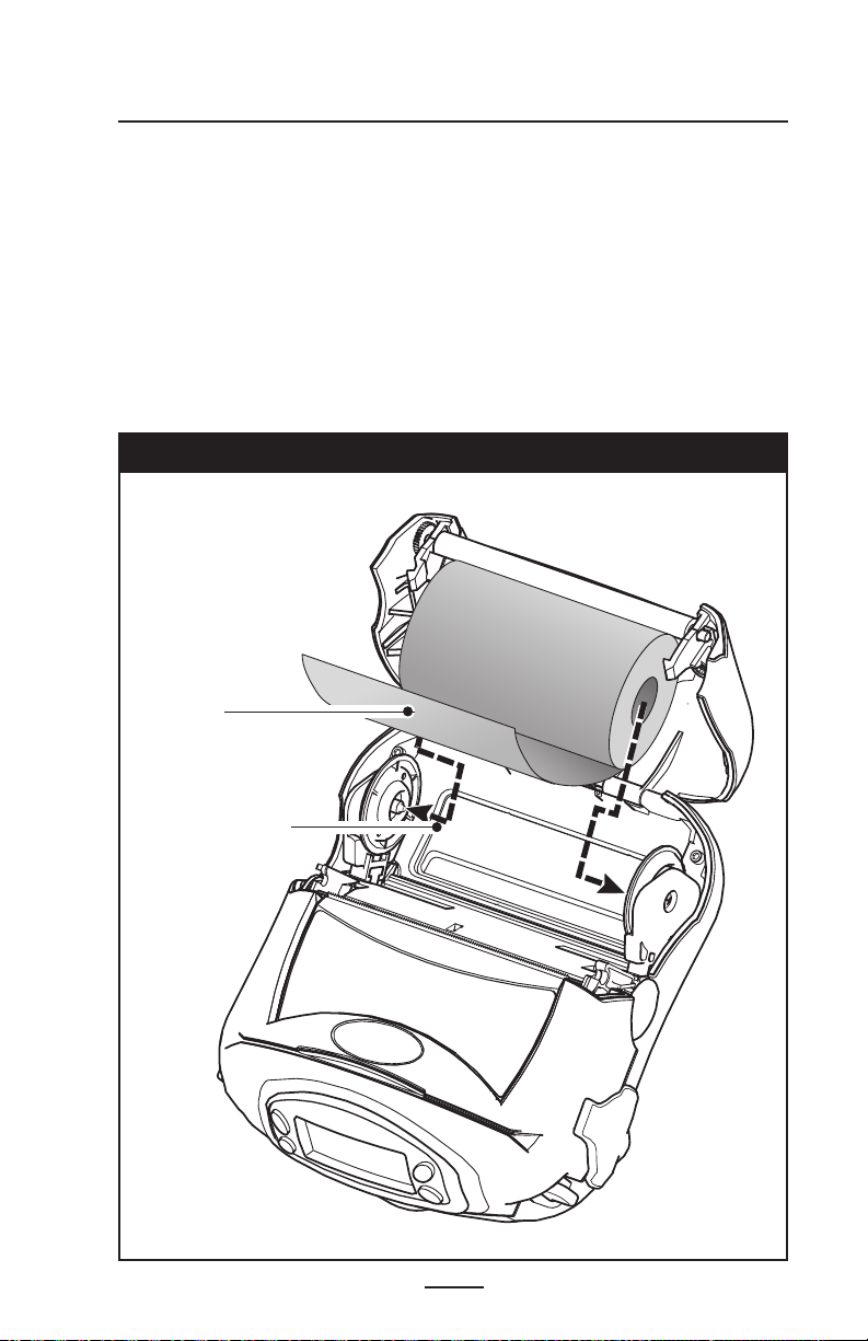
Loading Media From An Internal Supply
• Refer to Figure 6. Pull the media supports apart, insert
the roll of media between them, and let the media supports close. Ensure that the media pulls off the core in
the direction shown in Figure 6. The supports will adjust
themselves to the width of the media, and the roll of media should be able to spin freely on the supports.
Figure 6: Loading Media from an Internal Supply
Media Roll
Note direction
media pulls off the
roll.
Pull Media Supports
apart.
13
RW 420 User Guide
Page 14
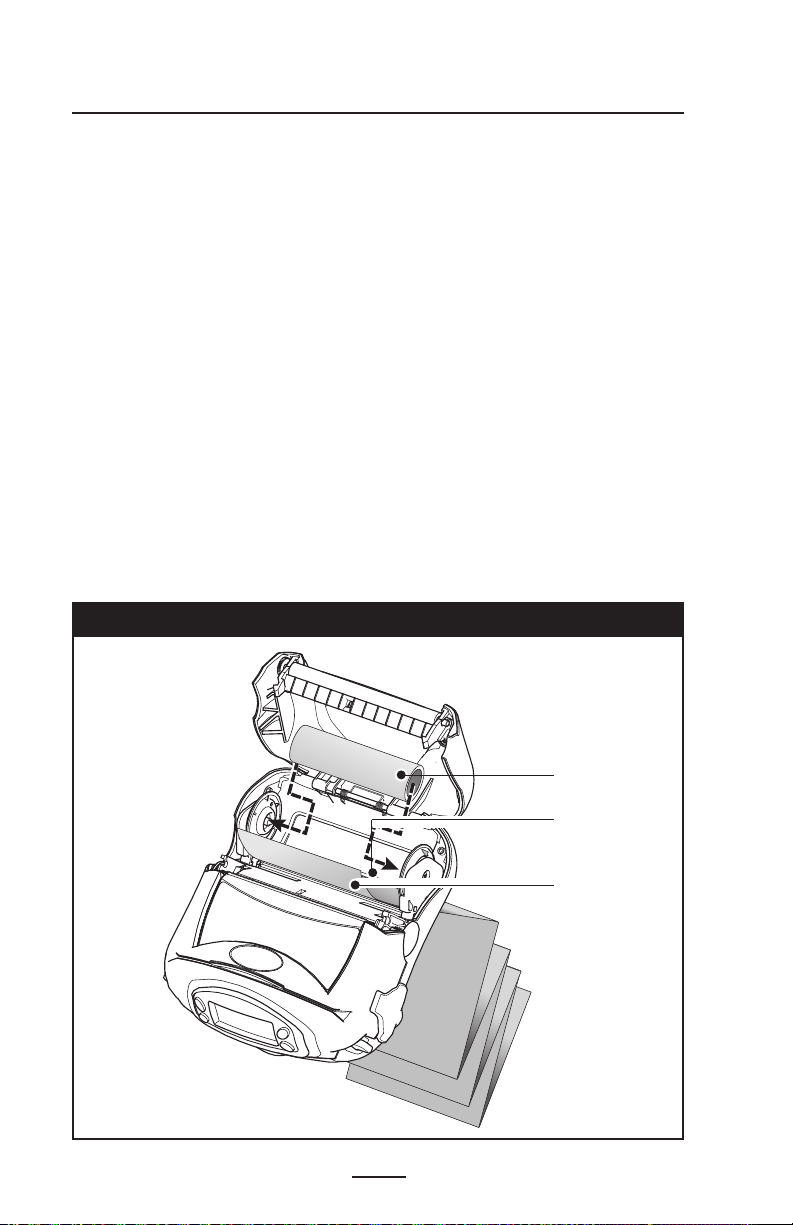
Loading Media From An External Supply
Refer to Figure 7. The RW 420 configured with the Ex-
ternal Media option has a loading slot in the rear of the
media compartment allowing you to use standard 4 in.
(101.6 mm) wide fanfold media from an external supply.
The external supply must be designed such that it does
not exert excessive drag as media is fed through the
printer, which could result in distorted printing.
Zebra offers a series of vehicle cradles for the RW 420
(p/ns AK17463-003 and AK17463-004) which incorporate
provisions for installation of an external media supply bin.
• Pull the media supports apart, insert a Media Spacer
(Zebra part number BA16625-1) between them, and let
the media supports close. Insert the media from the
external supply through the rear feed slot, between the
media guides and up through the media compartment as
shown. Make sure the side of the media you will be printing on faces the printhead.
Figure 7: Loading Media from an External Supply
14
RW 420 User Guide
Media Spacer
p/n BA16625-1
Feed media
through bottom
feed slot
Printing surface
of media must
face the printhead
Page 15

4. Close the Media Cover: Refer to Figure 8.
• Pull the media out of the printer as shown at “1.”
• Close the media cover as shown at “2”, ensuring that it
latches securely into place.
• Turn the printer on or press the Feed button if the
printer is already on.
The printer will advance a short strip of media and will
then be ready for printing.
Figure 8: Closing the Media Cover
Press Media
Cover firmly
when closing to
ensure it latches
in place.
Pull Media out
of the Printer
15
RW 420 User Guide
Page 16
Operator Controls
Control Panel
The control panel has buttons for the power on/off and
media feed functions and a display for providing information
regarding printer functions. Two keys provide easy navigation
and selection of menu options affecting many printer functions.
The “Scroll” button allows scrolling through the various op
tions and settings. The “Select” button allows selection of the
option or function displayed on the screen.
The top of the screen has a row of status icons which indi
cate the state of various printer functions:
Indicates a Bluetooth connection is established. A flashing icon indicates data transmission. This icon is functional only with RW 420 printers with a Bluetooth wireless
option installed.
Indicates that the printer is associated with a wireless Local Area Network (LAN) using an 802.11b compliant radio.
This icon is functional only with RW 420 printers with a
WLAN wireless option installed.
-
-
A flashing icon indicates low battery status. You
should suspend any printing operations and recharge or
replace the Battery Pack as soon as is convenient.
A flashing icon indicates that the media cover is open or
not properly latched.
A flashing icon indicates that a file is being downloaded
to the printer.
A flashing icon indicates that the printer does not detect
any media. This could indicate an out of media condition,
or improperly loaded media.
In addition to the status icons, the LCD on the control panel
can display many of the printer’s settings and functions as
text. Applications can be written to allow the user to view and
/or modify these settings using the scroll and select keys on
the display. Refer to the “LCD Functions Table” on the follow
ing pages for the full set of printer features that can be displayed.
16
RW 420 User Guide
Page 17
Zebra RW 420
Signal:0%
Battery (ok)
Latch: ok Rdr
MENU
The LCD has a backlighting option which allows viewing of
the screen in a dark environment, or provides better contrast
in a very bright environment. Use of the display backlight will
decrease the time the printer will run between charges. Refer
to the section “Extending Battery Life” for more information.
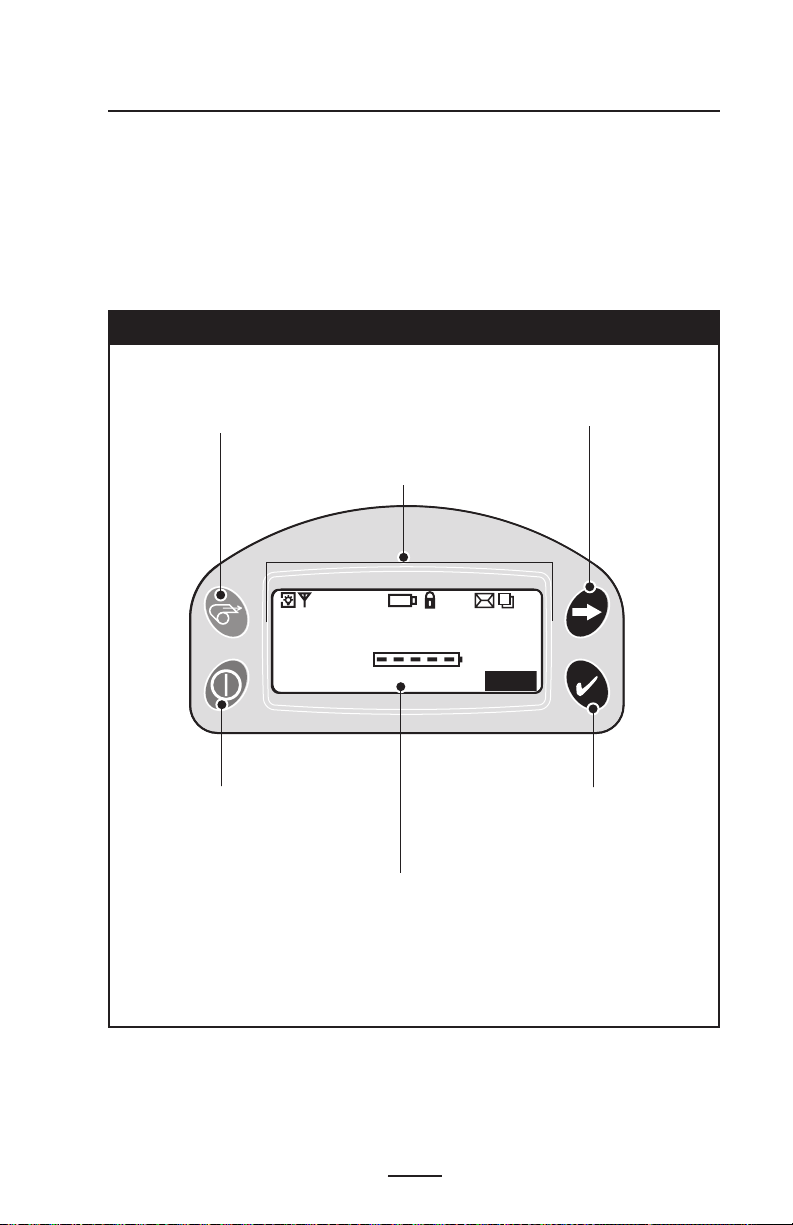
Figure 10: LCD Control Panel
Feed Button
Press to advance the media
one blank label or a software
determined length of journal
media.
Printer Status Icons
Indicates the status of
several printer functions
Scroll Button
Press to scroll
through the menu
choices on the LCD.
Power Button
Press to turn unit on. Press again
to turn unit off
RW 420 User Guide
Select Button
Press to select a menu
choice on the LCD.
LCD
See LCD Functions Table for an overview of
menu options
NOTE: LCD options are under specific applica
tion control. Not all options may be available In
your printer’s application.
17
-
Page 18
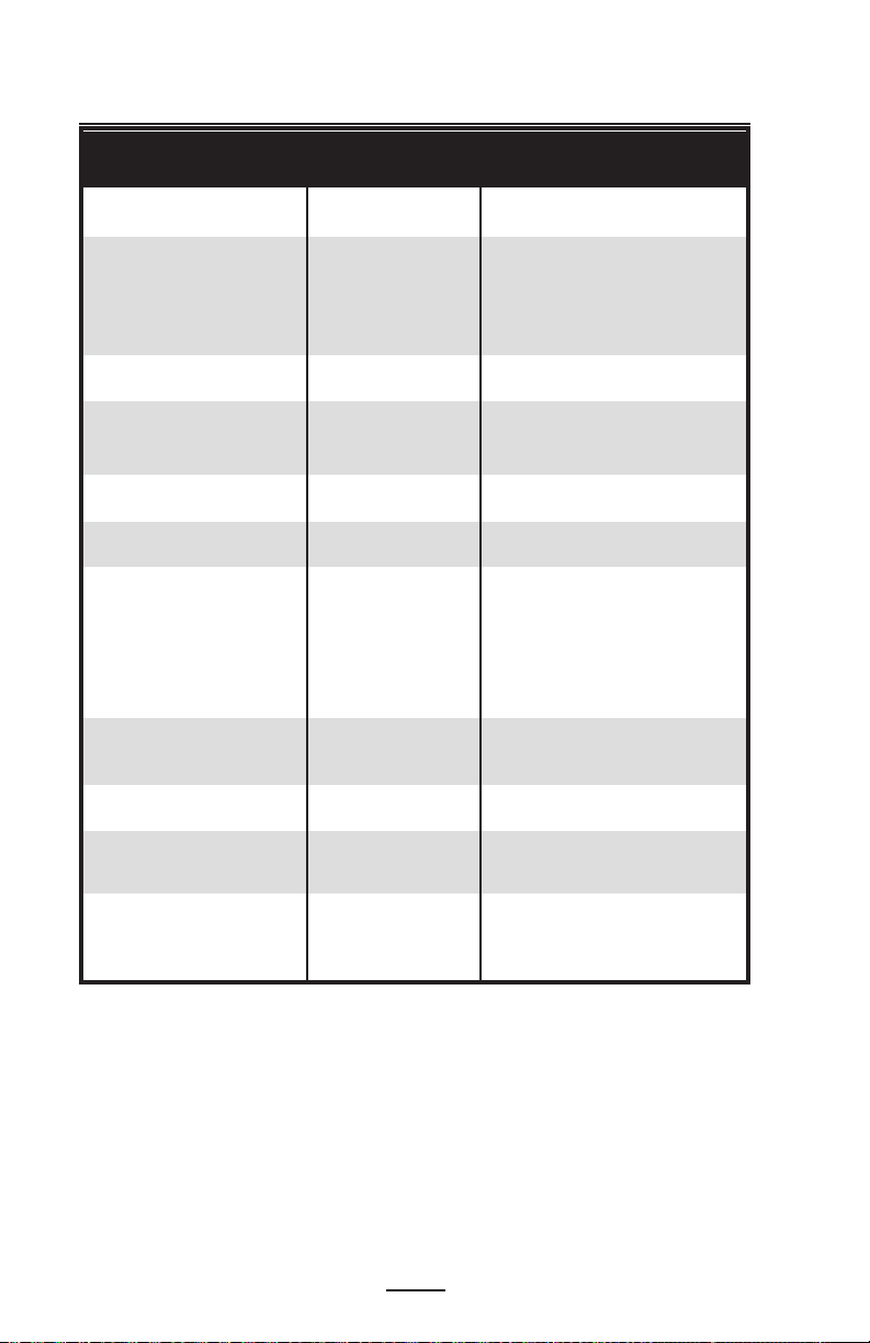
Extended LCD Functions
Function Default setting Scroll & Select Options
Sensor Type Bar • Bar
• Gap
Baud Rate 19200 • 9600
• 19200
• 32400
• 57600
• 115200
Data Bits 8 • 7
• 8
Parity N (none) • E (Even)
• N (None)
• O (Odd)
LCD Contrast 8 • Increase (15max.)
• Increase (15 max.)
No-activity Timeout1 120 sec. • Decrease (0 min.)
• Increase (120 max.)
• OFF
• ON (The 4 text lines
of display will be
Flip Screen OFF flipped 180 ° when the
printer is in the Cradle
Location of icons will
remain unchanged.
• 1 – Low
Audio Volume 3 • 2 – Medium
• 3 - High
Media Type Journal • Label
• Journal
LCD Backlight
time delay
• Off
Factory Reset No • No
(Resets all to • Yes
factory set values)
1
Momentary On • Momentary On w/
18
RW 420 User Guide
Page 19
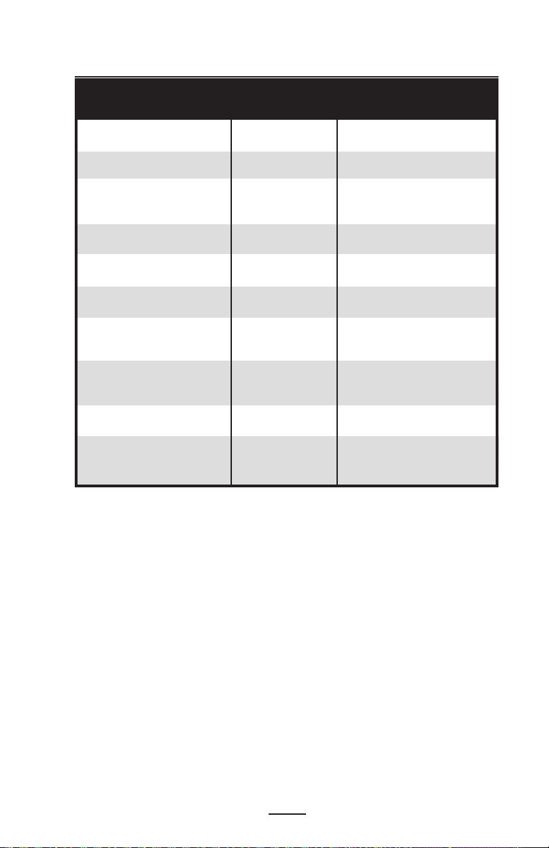
Display Functions Not Accessible from the Keypad
4
Function Default setting Scroll & Select Options
WLAN ID2 Factory Set N/A
Value
Tear-off 00 • Increase (max. = +10)
Position (Top of Form) • Decrease (min. = -120
• All protocols ON
Network & RF Settings • Protocols ON or OFF
individually
Bridge Mode off • OFF
• ON
DTR/ VBUS-Power Off OFF • ON
• OFF
Present-at 000 • Increase (max.= +120)
• Decrease (min. = 000
Displays current
Bluetooth parameters n/a Bluetooth operating
parameters
Displays current
802.11b WLAN parameters n/a 802.11b operating
parameters
Media Type Journal • Journal
• Label
Smart Card or • Off
MSR Card Off • Display “RDR”
Reader Status3
NOTES:
1. LCD Backlight turns on when any key other than FEED is pressed
2. Can be adjusted from the factory default using a PC running Zebra’s Label Vista
label creation program and a data cable link to the printer.
3. Card reader status is under application control, and is not user selectable.
4. The parameters listed above will appear on the display but can only be set using
a PC running Zebra’s Label Vista label creation program and a data cable link to the
printer.
19
RW 420 User Guide
Page 20

Verify the Printer Is Working
Before you connect the printer to your computer or portable
data terminal, make sure that the printer is in proper working
order. You can do this by printing a configuration label using
the “two key reset” method. If you can’t get this label to print,
refer to “Troubleshooting.”
Printing a Configuration Label
1. Turn the printer off. Load the media compartment with
journal media (media with no black bars printed on the
back)
2. Press and hold the Feed Button.
3. Press and release the Power button and keep the Feed
button pressed. When printing starts, release the Feed
button.
The unit will print a line of interlocking “x” characters to
ensure all elements of the printhead are working, print out the
version of software loaded in the printer and then print two
reports.
The first report indicates model, ROM version, serial num
ber, baud rate, etc. The second report prints out more detailed information on the printer’s configuration and parameter
settings. If no second report appears, there is no application
loaded. (See the Troubleshooting Section for a sample printout and a further discussion on how to use the configuration
label as a diagnostic tool.)
-
20
RW 420 User Guide
Page 21

Connecting the Printer
The printer must establish communications with a host
terminal which sends the data to be printed. Communications
occur in three basic ways:
• By a cable between the printer and its host terminal using
either RS232C or USB protocols.
• By means of a Bluetooth short-range radio frequency link.
• By means of a wireless LAN (Local Area Network) per
802.11b specifications.
While the RW 420 can be equipped with both a Bluetooth radio and a
802.11b radio they cannot be operated concurrently.
Figure 11: Communications Port
USB Port
Align Locking
Plug features
with these cutouts.
Rotate clockwise to lock the
cable in place;
counterclockwise to unlock
RS232 Port
the cable.
Cable Communications
Serial (RS232C)
CAUTION. The power should be turned off before connecting or
disconnecting the communications cable.
All RW 420 printers can communicate by cable; the specific
cable supplied with your printer will vary with the host terminal. The 10- pin modular connector on your communications
cable plugs into the serial (RS232C) communications port on
the side of the printer. Plug the connector into the RS232C
port and ensure the locking device has clicked into position.
Then press the Locking Plug into the opening around the connector, aligning its locking features with the cutouts on the RW
420 case. Turn the Locking Plug clockwise one-quarter turn to
secure it in place.
The other end of the cable must be plugged into the host
21
RW 420 User Guide
Page 22

terminal as shown in Figure 12, or to a serial port on a computer as shown in Figure 13. Communications between the
terminal and the printer are controlled by the applications running on the terminal and the printer.
USB
RW 420 Printers also can communicate by cable via the
USB protocol. The USB port is a USB Mini-AB type connector
located directly above the 10- pin modular connector used for
RS232C communications. (Refer to Figure 11)
The RW 420 is configured with the USB Open HCI interface
driver allowing it to communicate with Windows
®
based de-
Figure 12: Communications to a Terminal
Communications
Printer Communications
Port
Cable
Part number varies. Refer
to Appendix A
Figure 13: Communications to a PC
RS232 Communications
Cable
Refer to Appendix A for
part number
22
RW 420 User Guide
USB
Communications
Cable
Refer to Appendix A
for part number
Page 23

vices. (USB drivers are included in the Zebra Universal Driver
which can be downloaded from www.zebra.com/drivers.) Other
terminals or communications devices may require the installation of special drivers to use the USB connection. Consult the
factory for further details.
Wireless Communications
Wireless Communications with Bluetooth®
The following section only applies when the ZBR3 Bluetooth Radio
(FCC ID: I28MD-BTC2TY2) is installed in a RW 420. The antenna used for this transmitter
must not be co-located or must not operate in conjunction with any other antenna.
“Bluetooth” is a worldwide standard for the exchange of
data between two devices via radio frequencies. Bluetooth
radios are relatively low powered to help prevent interference with other devices running at similar radio frequencies.
This limits the range of a Bluetooth device to about 10 meters
(about 32 feet).
Both the printer and the device it communicates with must
follow the Bluetooth standard.
Bluetooth Networking Overview
Bluetooth software is always running in the background,
ready to respond to connection requests. One device (known
as the master or the client) must request a connection with another. The second device (the slave or the server) then accepts
or rejects the connection. A Bluetooth enabled RW 420 printer will normally act as a slave creating a miniature network
with the terminal sometimes referred to as a “piconet.”
For the most part, communications using Bluetooth are initiated and processed without any operator intervention.
Each Bluetooth enabled RW 420 printer has a unique Blue
tooth Device Address (BDA) loaded into its radio module
when manufactured.
Exposure to Radio Frequency Radiation
The radiated output power of this internal Bluetooth radio is far
below the FCC radio frequency exposure limits. Nevertheless,
this Bluetooth radio must be used in such a manner that the
antenna is 2.5 cm. or further from the human body.
The radio and antenna are mounted internally in this printer
such that when the printer is worn with the back of the printer
-
23
RW 420 User Guide
Page 24

against the body and the front of the printer (where paper exits)
away from the body, then the 2.5 cm distance between the
antenna and the users body will be met. Do not use the printer
in an unauthorized manner.
The internal Bluetooth radio operates within guidelines found
in radio frequency safety standards and recommendations.
The level of energy emitted is far less than the electromagnetic
energy emitted by other wireless devices such as mobile
phones.
European Regulatory Information for the ZBR3 Bluetooth Radio
This device is intended for use in all EU and EFTA member states.
Europe – EU Declaration of Conformity
This device complies with the essential requirements of the R&TTE Directive 1999/5/
EC. The following test methods have been applied in order to prove presumption of
compliance with the R&TTE Directive 1999/5/EC:
• EN 60950: 2000
Safety of Information Technology Equipment
• EN 300 328-2 V1.4.1 (2003-04)
Technical requirements for spread-spectrum radio equipment
• EN 301 489-1/-17 V1.4.1/1.2.1 (2002-08)
EMC requirements for spread-spectrum radio equipment.
This device is a 2.4 GHz wireless LAN transceiver, intended for indoor home and
office use in all EU and EFTA member states.
Important Notice:
0336
This device is a portable RF printer intended
for commercial and industrial use in all EU and
EFTA member states.
24
RW 420 User Guide
Page 25

Wireless Local Area Network (WLAN) Module Using CF Radio
The following section only applies when the CF (Compact Flash) WLAN module (With
FCC ID: I28MD-RW4137) is installed in a RW 420 printer (note that only one of the radio
options can be installed in the printer at one time). The FCC ID number is on the serial
number label on the back of the printer and can be read with the module installed.
WARNING: Use of a RW 420 printer with the radio module
marked with “FCC ID: I28MD-RW4137” meets the FCC
requirements for radio frequency (RF) radiation exposure in the
standard body worn configuration with no minimum separation.
In this configuration, which applies whether the belt clip or
shoulder strap is used, the face of the printer from which paper
is transported is facing away from the user’s body. The standard
configuration must always be used when the printer is body
worn.
RW 420 printers with this radio option have been SAR tested.
The maximum SAR value measured for each model was T. B.D.
W/kg averaged over 1 gram.
European Regulatory Information for this Radio
AT BE CY CZ DK
EE FI FR DE GR
HU IE IT LV LT
LU MT NL
SK SI ES SE GB
Note: -Member states in the EU with restrictive use for this device are crossed
out!
This device is also authorized for use in all EFTA member states (
PL PT
CH, IS, LI, NO)
0336
Important Notice:
This device is a portable RF printer intended
RW 420 User Guide
for commercial and industrial use in all EU and
EFTA member states except in France where
restrictive use applies.
25
Page 26

Europe – EU Declaration of Conformity
This device complies with the essential requirements of the R&TTE Directive 1999/5/
EC. The following test methods have been applied in order to prove presumption of
compliance with the R&TTE Directive 1999/5/EC:
• EN 60950: 2000
Safety of Information Technology Equipment
• EN 300 328-2 V1.2.1 (2001-12)
Technical requirements for spread-spectrum radio equipment
• EN 301 489-17 V1.2.1 (2002-08)
EMC requirements for spread-spectrum radio equipment.
This device is a 2.4 GHz wireless LAN transceiver, intended for indoor home and
office use in all EU and EFTA member states, except in France where restrictive use
applies.
The use of this frequency band in France is subject to restrictions. You may only
use channels 10 and 11 (2457 and 2462 MHz) on French territory, except in those
French departments as listed in the table below where channels 1-13 (24122472 MHz) may be used. For more information see
http://www.art-telecom.f
01 Ain 36 Indre 69 Rhone
02 Aisne 37 Indre et Loire 70 Haute Saone
03 Allier 39 Jura 71 Saone et Loire
05 Hautes Alpes 41 Loir et Cher 72 Sarthe
08 Ardennes 42 Loire 75 Paris
09 Ariege 45 Loiret 77 Seine et Marne
10 Aube 50 Manche 78 Yvelines
11 Aude 54 Meurthe et Moselle 79 Deux Sievres
12 Aveyron 55 Meuse 82 Tarn et Garonne
16 Charente 57 Moselle 84 Vaucluse
19 Correze 58 Nievre 86 Vienne
2A Corse Sud 59 Nord 88 Vosges
2B Haute Corse 60 Oise 89 Yonne
21 Cote d’Or 61 Orne 90 Territoire de Belfort
24 Dordogne 63 Puy de Dome 91 Essonne
25 Doubs 64 Pyrenees Atlantique 92 Hauts de Seine
26 Drome 65 Hautes Pyrenees 93 Seine St Denis
27 Eure 66 Pyrenees Orientales 94 Val de Marne
32 Gers 67 Bas Rhin
35 Ille et Vilaine 68 Haute Rhin
r
http://www.anfr.fr/ and/or
26
RW 420 User Guide
Page 27

Wireless Local Area Network Overview
RW 420 printers can be equipped with several radio options
which use the industry standard 802.11b protocol.
• RW 420 printers with a Compact Flash (CF) radio module
can be identified by the FCC ID number “I28MD-RW4137”
and other regulatory information on the serial number
label on the back of the unit.
Printers so equipped allow wireless communication as a
node within a Wireless Local Area Network (WLAN) and its
wireless capabilities allow communications from any point
within the WLAN’s perimeter.
Methods of establishing communications to RW 420 printers
will vary with each WLAN application. General information on
establishing WLAN communications can be found in either the
“Mobile Printing Systems CPCL Programming Manual” or the
“Quick Start Guide for Mobile Wireless Printers.” Both docu
ments are available on-line at:
http://www.zebra.com/manuals
-
More information and WLAN configuration utilities may also
be found in Zebra’s Label Vista™ program (version 2.8 and
later). Label Vista may be downloaded from the Zebra Web
site at:
Setting Up the Software
http://www.zebra.com/SD/product _ LabelVista.htm
RW 420 printers use Zebra’s CPCL Programming language
which was designed for mobile printing applications. CPCL
is fully described in the ”Mobile Printing Systems CPCL Programming Manual”, available on-line from Zebra’s Web site at:
http://www.zebra.com/manuals
27
RW 420 User Guide
Page 28

You can also use Label Vista™, Zebra’s Windows™
based label creation program which uses a graphical in
terface to create and edit labels in the CPCL language.
Label Vista is available on-line from Zebra’s Web site at:
http://www.zebra.com/SD/product _ LabelVista.htm
RW 420 printers also support an interpreter for ZPL II®, or
EPL programming languages. To use ZPL II or EPL, refer to
the appropriate Programming Guides available on-line from
Zebra’s Web site. If you choose to use a third party label prep
aration system, follow the installation instructions included in
the package.
-
28
RW 420 User Guide
Page 29

Card Reader Options
Zebra RW 4 20
Signa l:0%
Batte ry (ok)
Latch : ok Rd r
MENU
The RW 420 can be equipped with optional Magnetic Stripe
and Smart Card readers. The magnetic stripe card reader allows the user to swipe magnetic stripe cards such as credit
cards through a slot in the printer and then read and process
the data contained in the card.
In a similar manner the Smart Card reader can read the in
formation written in the microchip embedded in Smart Cards,
and process the information in the chip in a variety of ways
depending on the printer’s application.
Figure 14: Magnetic Stripe Reader Status Indicator
“Rdr” indicates MSR
is enabled.
-
Magnetic Stripe Reader
The status of the Magnetic Stripe Reader (MSR) is indicated
in three possible ways:
• Reader status is displayed on the Main Menu LCD as
shown above in Figure 14.
• The LCD backlight flashes to indicate status (3 flashes =
enabled, 2 flashes = disabled).
• Chimes indicates the reader status (3 chimes = enabled,
2 chimes = disabled).
29
RW 420 User Guide
Page 30

The MSR is used as follows:
1. When the reader is enabled, place the card into the
reader slot as shown. The magnetic stripe (typically on
the back of the card) must face the bottom of the printer,
and be inserted into the bottom of the card reader slot as
shown in Figure 15.
2. Slide the card through the slot. The card will be read
if slid in either direction. Depending on the application
software, the printer will sound one chime when a scan is
successful .
3. If the card did not read, slide it back through the slot in
the opposite direction.
Figure 15: Using the Magnetic Stripe Reader
Magnetic Stripe Card
Place the Card in the reader slot with the mag-
Magnetic Stripe
Reader Slot
netic stripe facing down as shown.
30
RW 420 User Guide
Card can be read in
both directions.
Page 31

Smart Card Reader
The optional Smart Card reader is used as follows:
1. The LCD will display “RDR” to indicate the Smart Card
reader is active. (Some reader applications may flash the
display backlight and/or chime three times to indicate the
reader status is “ready.”) At this time, the Printer is acting
only as a Smart Card reader connected to the host terminal; all other printer functions are suspended.
2. Insert the card into the reader slot as shown in Figure 16.
The microchip imbedded in the card must be oriented
facing the bottom of the printer and must be completely
inserted into the Reader Slot to scan successfully .
3. Depending on the application software, the printer will
sound a chime after a successful transaction.
4. After the card has been successfully read the Printer can
resume normal printing operations and the Smart Card
can be removed.
Figure 16: Using the Smart Card Reader
Smart Card Reader
Slot
31
RW 420 User Guide
Insert Smart Card
with microchip
facing down.
Insert Smart Card
completely into
Printer.
Page 32

Using the Accessories
Belt Clip
Refer to Figure 17. All RW 420 printers are equipped with a
belt clip as standard. To use: hook the clip over your belt, and
ensure that the clip is securely attached to the belt. The belt
clip will pivot to allow you to move freely while wearing the
printer.
Figure 17: Using the Belt Clip
Clip printer
to belt
32
RW 420 User Guide
Printer can
pivot freely
Page 33

Adjustable Shoulder Strap
Refer to Figure 18. If your printer is equipped for the shoulder strap option: snap each end of the shoulder strap into the
“D” rings in the top of the printer. Slide the buckle away from
or towards the printer until you achieve the desired length.
Figure 18: Using the Shoulder Strap
Hold Buckle
Pull Strap
here to
lengthen
Pull Strap
here to
shorten
Snap in to
“D” rings on
printer
33
RW 420 User Guide
Page 34

Cradle
Zeb ra R W 4 20
Sig nal: 0%
Bat tery (o k)
Lat ch: ok Rdr
ME NU
Zeb ra R W 4 20
Sig nal: 0%
Bat tery (o k)
Lat ch: ok Rdr ME NU
Zeb ra R W 4 20
Sig nal: 0%
Bat tery (o k)
Lat ch: ok Rdr
ME NU
The RW 420 can be used in conjunction with a docking
Cradle. When the printer is “docked” the Cradle will charge
the printer’s battery and allow the printer to print, receive and
transmit data as usual. The Cradle can provide power from
a 12 VDC power supply either from a power take-off point in
a vehicle or from an external power supply running off A.C.
power. Refer to the documentation supplied with the Cradle
for more information.
Installing the Printer in the Cradle
It is recommended as a safety precaution that the
adjustable shoulder strap be removed prior to docking the
Printer. This precaution ensures the strap will not interfere with
proper operation of the vehicle.
• Remove the Docking Connector Cover from the bottom
of the printer, and retain it for future use. (Refer to Figure
20.)
• Place the bottom of the printer over the two pins in the
Cradle.
• Rock the top of the Printer into the Cradle and press
firmly until it latches in place.
• Ensure the Cradle power indicator is lit and turn the
printer on.
You can load media (including media from an external supply) and perform cleaning operations normally when the
RW 420 Printer is installed in the Cradle .
The RW 420 will allow the four display lines on the control
panel to be rotated 180º when the printer is docked. This
allows for easier reading of the display when the Cradle is
Figure 19: Display Rotated for Cradle Installation
Normal Display in
Cradle
34
RW 420 User Guide
Display rotated in
Cradle
Page 35

Figure 20: Installing the Printer into the Cradle
Remove
and
retain the
Docking
Connector
Cover
Charge
Indicator
Rock the Printer
into the Cradle to
latch it in position.
RW 420 User Guide
Power Indicator
Always Green when power is on
Place the
Printer over
the retaining
pins in the
Cradle.
35
Page 36

mounted vertically. Refer to Figure 19.
Removing the Printer from the Cradle
Refer to Figure 21.
• Turn the Printer off.
• Push on the latch on the Cradle and rock the top of the
printer away from the Cradle.
• Lift the Printer out from the Cradle.
Replace the Docking Connector Cover if you will be us
ing the Printer for an extended period of time away from the
Cradle.
Figure 21: Removing the Printer from the Cradle
Press the
Latch button
to release the
Printer.
Rotate the
Printer out
of the
Cradle.
Lift the printer
free of the
retaining pins.
36
RW 420 User Guide
Page 37

Preventive Maintenance
Extending Battery Life
• Avoid exposing the battery to direct sunlight or temperatures over 104° F (40° C).
• Always use a Zebra charger designed specifically for
Lithium-Ion batteries. Use of any other kind of charger
may damage the battery.
• Use the correct media for your printing requirements. An
authorized Zebra re-seller can help you determine the
optimum media for your application.
• If you print the same text or graphic on every label, consider using a preprinted label.
• Choose the correct print darkness, and print speed for
your media.
• Use software handshaking (XON/XOFF) whenever possible.
• If your printer has the optional LCD display, use the display backlight only when necessary. Turn it off whenever
it is not needed.
• Remove the battery from the printer if it won’t be used for
a day or more and you’re not performing a maintenance
charge.
• Consider purchasing an extra battery.
• Remember that any rechargeable battery will lose its
ability to maintain a charge over time. It can only be
recharged a finite number of times before it must be
replaced. Always dispose of used batteries properly.
Refer to Appendix D for more information on proper battery disposal.
• Don’t print while the LI 72 Wall Charger is plugged into
the unit. Unreliable battery charging can result.
Cleaning Instructions
CAUTION- Use only cleaning agents specified. Zebra
Technologies Corporation will not be responsible for damage
caused by any other cleaning materials used on this printer.
Clean the printer with either the cleaning pen supplied with the
printer or a cotton swab saturated with alcohol.
WARNING: To avoid possible personal injury or damage
to the printer, never insert any pointed or sharp objects into the
printer. The Tear Bar has sharp edges. Use care when cleaning
the Tear Bar or the Printhead to avoid possible personal injury.
37
RW 420 User Guide
Page 38

RW 420 Cleaning
Area Method Interval
Use the supplied cleaning pen
Printhead
(Figure 22)
Tear bar
(Figure 22)
or 70% isopropyl alcohol on a
cotton swab to clean the print
elements from end to end (the
print elements are located
in the thin gray line on the
printhead).
Clean thoroughly with the
cleaning pen or 70% isopropyl
alcohol and a cotton swab.
After every five rolls of
media (or more often, if
needed)
Platen Roller
(Figure 22)
Exterior
Interior
(Figure 22)
Rotate the platen roller and
clean it thoroughly with the
cleaning pen or 70% isopropyl
alcohol and a cotton swab.
Water-dampened cloth
Brush/air blow. Ensure the Bar
Sensor and Gap Sensor windows
are free of dust.
Figure 22: Cleaning the RW 420
Printhead
Elements
Bar Sensor
As needed
After every five rolls of
media (or more often, if
needed)
Platen Surface
Tear Bar
Gap Sensor
38
RW 420 User Guide
Page 39

Troubleshooting
LCD Control Panel Indicators
The top of the display shows several icons which indicate
various printer functions. Check the indicator status, then refer
to the Troubleshooting topic referenced in the chart to resolve
the problem.
Status Icon Condition Indication Ref. to Topic #
Steady 802.11b RF Link established n/a
Off No 802.11b RF Link 6
Steady Bluetooth Link established n/a
Flashing Transmitting/Receiving n/a
via Bluetooth
Off No Bluetooth Link 6
Flashing Low Battery 3, 6, 7
Flashing Head latch not closed 9, 11
Steady data processing in process 8
Flashing Out of Media 9,11
Blank Screen n/a No application 1,13
39
RW 420 User Guide
Page 40

Troubleshooting Topics
1. No power
• Check that battery is installed properly
• Recharge or replace battery as necessary. (
of used batteries properly. Refer to Appendix D for
more information on proper battery disposal.)
2. Media does not feed:
• Ensure Media Cover is properly closed and latched.
• Check media supports for any binding.
3. Poor or faded print or flashing icon:
• Clean print head.
• Check battery and recharge or replace as necessary.
• Check quality of media.
4. Partial/missing print:
• Check media alignment.
• Clean print head.
• Ensure Media Cover is properly closed and latched.
5. Garbled print:
• Check baud rate.
6. No print:
• Check baud rate.
• Replace battery.
Always dispose of used batteries
properly. Refer to Appendix D for more information on
proper battery disposal.
• Check cable to terminal.
• Wireless units (Bluetooth or 802.11b) only: Establish RF
Link. Restore LAN associativity on 802.11b wireless units.
• Invalid label format or command structure — put printer in
Communications Diagnostic (Hex Dump) Mode to diagnose
problem (refer to Troubleshooting Tests section).
7. Reduced battery life
• Check battery date code — if battery is one to two years
old, short life may be due to normal aging.
• Replace battery. (
Always dispose of used batteries
properly. Refer to Appendix D for more information on
proper battery disposal.)
8. Flashing icon:
• No application or application corrupted: reload program.
•Flashing indicator is normal while data is being received.
Always dispose
40
RW 420 User Guide
Page 41

9. Flashing or icon :
• Check that media is loaded.
• Ensure Media Cover is properly closed and latched.
10. Skips labels (only when using label stock):
• Check media for top of form sense mark or label gap.
• Check that the maximum print field has not been exceeded
on label.
• Ensure bar or gap sensor is not blocked or malfunctioning.
11. Communication Error:
• Check media is loaded.
• Ensure Media Cover is properly closed and latched and
error indicators are off.
• Check baud rate.
• Replace cable to terminal.
12. Label Jam:
• Open media cover.
• Apply generous amount of alcohol to printer in area of
jammed label.
13. Blank LCD Screen
• No application loaded or application corrupted: reload
program.
14. Magnetic Strip Card or Smart Card Won’t Read
• Ensure the “RDR” text is displayed, indicating card reader is
enabled. (Refer to the Operator Controls section.)
• Ensure card is inserted with the magnetic stripe or
microchip facing in the correct direction.
• Check card for excessive wear or damage to either the
magnetic strip or the microchip.
15. Battery Pack Is Hard to Insert
• The battery packs for the RW 420 and QL 420
model printers are similar in size and shape, but not
interchangable. Verify you are using the correct battery
pack.
• Battery pack part number for the RW 420 is CT17102-2.
41
RW 420 User Guide
Page 42

Troubleshooting Techniques
Printing a Configuration Label
To print out a listing of the printer’s current configuration fol-
low these steps:
1. Turn the printer off. Load the media compartment with
journal media (media with no black bars printed on the
back)
2. Press and hold the Feed Button.
3. Press and release the Power button and keep the Feed
button pressed. When printing starts, release the Feed
button.
Refer to Figures 23 through 23b for a sample configura
tion printout.
Performing a Forced Shutdown
It the printer has locked up and is not responding to any operator inputs or external commands, from either a connected
terminal or a linked LAN, you can perform a forced shutdown.
• If the printer software locks up during normal operation,
force the printer to shut down by pressing and holding
the Power Button for 3 seconds.
• If you try to turn the printer off normally and the soft
ware locks up, the printer will automatically shut itself off
after a 10 second delay.
• If you try to turn the printer off and it does not respond,
you can force an immediate shut down by pressing and
holding the Power Button again within 10 seconds.
A forced shutdown will preserve the printer’s data and set-
tings
Communications Diagnostics
If there’s a problem transferring data between the computer
and the printer, try putting the printer in the Communications
Diagnostics Mode (also referred to as the “DUMP” mode). The
printer will print the ASCII characters and their and their text
representation (or the period ‘.’, if not a printable character) for
any data received from the host computer
To enter Communications Diagnostics Mode:
1. Print a configuration label as described above.
2. At the end of 2nd diagnostics report, the printer will print:
“Press FEED key to enter DUMP mode.”
-
-
42
RW 420 User Guide
Page 43

3. Press the FEED key. The printer will print: “Entering
DUMP mode.”
NOTE: If the FEED key is not pressed within 3 seconds, the printer will print “DUMP
mode not entered” and will resume normal operation.
4. At this point, the printer is in DUMP mode and will print
the ASCII hex codes of any data sent to it, and their text
representation (or “.” if not a printable character).
Additionally, a file with a “.dmp” extension containing the
ASCII information will be created and stored in the printer’s
memory. It can be viewed, “cloned” or deleted using the Label
Vista application. (Refer the Label Vista documentation for
more information.)
To terminate the Communications Diagnostics Mode and re
turn the printer to normal operations:
1. Turn the printer OFF.
2. Wait 5 seconds.
3. Turn the printer ON.
Calling Technical Support
If the printer fails to print the configuration label, or you encounter problems not covered in the Troubleshooting Guide,
contact Zebra Technical Support. Technical Support addresses and phone numbers for your area can be found in Appendix D of this manual. You will need to supply the following
information:
• Model number/type (e.g. RW 420)
• Unit serial number (14 digit number, including dashes)
The serial number is found on the large label on the back
of the printer. It is also reported in the configuration label
printout. (Refer to Figures 23 through 23b.)
• Product Configuration Code (PCC) (15 digit number, including dashes). The PCC number for an RW 420 Printer
will begin with “RW4” and is printed above the unit serial
number on the back of the unit.
-
43
RW 420 User Guide
Page 44

Print Head Test
End of First Report
Unit Serial Number
Software and
Firmware installed
Settings for
RS232 and USB
communications
via cable
Report appears
only on units with
wireless options
installed.
Units with no
wireless options
will print an empty
line and resume
printing
This example has a
Bluetooth module
installed. (Refer to
pages 23-24 for
more details.)
Figure 23: Configuration Label Example
44
RW 420 User Guide
Information on
TCP/IP and LAN
addresses and
settings.
Page 45

Information on any
installed 802.11b
wireless devices
In this example,
an 802.11b WLAN
card has been
detected.
List of peripherals
installed. In this
example the
printer has the
Mag Card and
Smartcard reader
option, and the
wireless expansion
module has an
802.11b and
Bluetooth wireless
module1.
List of power
mangement
settings. Also
includes a count
of the number of
times the unit has
been powered on.
1. Dual radio units as illustrated above are not yet offered for sale. This option will be
offered after initial product release.
Figure 23a: Configuration Label Example (continued)
45
RW 420 User Guide
Page 46

(my 2010.CPF)
(my 2020.CPF)
myfont .FNT
myfont2 .FNT
myfont3 .FNT
my_2010 .CPF
my_2020 .CPF
Flash Memory Size
RAM Size
Maximum Label
Size
Resident Fonts
Installed
Resident
Pre-scaled Font
Pre-scaled fonts
(.cpf) listed
separately
Files Loaded in
Printer Memory (will
include Pre-scaled
or Scalable Fonts)
Amount of Memory
Available
Figure 23b: Configuration Label Example (continued)
46
RW 420 User Guide
End of Configuration
Report
Page 47

Specifications
NOTE.- Printer specifications are subject to change without
notice.
Printing Specifications
Print Width Up to 4.09 in. (103.8 mm)
Print Speed 3 in. /second
76.2 mm /second)
Distance from .20 in. (5 mm)
Print Element 41 dots
to Tear Edge
Print Head Life, 1,964,160 in. (50 Km)
calculated nominal
Print Density 203 dots/inch (8 dots/mm)
Memory/Communications Specifications
Flash Memory 4 MB flash (standard)
RAM Memory 8 MB RAM (standard)
RS-232C serial port (RJ-45 connector)
Configurable Baud rate (from 9600 to 57.6
Standard Kbps), parity and data bits.
Communications Software (X-ON/X-OFF) or hardware (DTR/STR)
communication handshake protocols.
USB 2.0 Full Speed Interface (12 Mbps))
Bluetooth compatible 2.4 GHz SRRF link
Optional Wireless
Communications Wireless LAN capabilities comply with 802.11b
protocols
47
RW 420 User Guide
Page 48

Communications Ports
USB
Signal
Pin# Name Type Description
1 VBUS - USB Bus Power
2 USB - bi-directional I/O signals
3 USB + bi-directional I/O signals
4 USB_ID - Identifies A/B connector
5 Return - Ground
RS232
Signal
Pin# Name Type Description
1 NC no connect
2 NC no connect
3 RXD input Receive Data
4 TXD output Transmit Data
5 DTR output Data Terminal Ready
set high when printer is on.
6 GND Ground
7 DSR input Data Set Ready
low to high transition turns
printer on, high to low transi tion turns printer of f (if en-
abled)
8 RTS output Request To Send
set high when printer is ready
to accept a command or data
9 CTS input Clear To Send from host
10 NC no connect
48
RW 420 User Guide
Page 49

USB
1
10
RS232
Figure 24: Communication Ports
5
1
49
RW 420 User Guide
Page 50

Media Specifications
Media Width 2.0 in. to 4.1 in.
(50.8 to 104.1 mm)
Max. continuous receipt 143 in. (3620 mm)
(w/std. memory)
Inter-label Gap. 0.08 in. to 0.16 in. (0.12 in. preferred)
(2 mm to 4 mm [3 mm preferred])
Label Thickness .0025” to .0065” (.064 mm to .165 mm)
Max. Label Roll dia. 2.25 in. (57 mm) O.D.
Label Inner Core .75 in. (19 mm) minimum dia;
1.38 in. (35 mm) optional set ting
Black Mark The reflective media black marks should
Dimensions extend past the centerline of the roll.
Media Minimum mark width: 0.5” (12.7mm)
Requirements perpendicular to edge of media, centered within
the width of the roll.
Mark length: 0.094” (2.4 mm) parallel to edge of
media
Use Zebra brand direct thermal media that is outside wound. Media may be
reflective (black mark) sensing, or transmissive (gap) sensing, die-cut, or
continuous. RW 420 configured with the External Media option will accept fanfold
media used with an external media supply.
For die-cut labels, use only full auto dies.
50
RW 420 User Guide
Page 51

Font/Bar Code Specifications
Standard Fonts: 25 bit-mapped fonts; 1 scalable
font (CG Trimvirate Bold Condensed*)
Fonts Available Downloadable optional bit-mapped & scalable
fonts via Label Vista sof tware.
Optional International character sets:
Chinese 16 x 16 (trad), 16 x 16 (simplified),
24 x 24 (simplified); Japanese 16 x 16, 24 x 24;
Hebrew/Arabic
*contains UFS T from Ag fa Mon otype Corporat ion
Codabar
UCC/EAN 128
UCC-128 Composite A/B/C
Code 39
Code 93
EAN 8/JAN 8, 2 and 5 digit extensions
Linear Bar Codes EAN-8 Composite
Available EAN 13/JAN 13, 2 and 5 digit extensions
EAN-13 Composite
lnterleaved 2 of 5
MSI/Plessey
FIM/POSTNET
UPC-A, 2 and 5 digit extensions
UPCA Composite
UPC E, 2 and 5 digit extensions
UPCE Composite
MaxiCode
PDF 417
2-D Bar Codes Datamatrix (using ZPL emulation)
Available RSS: RSS-14 Truncated
RSS-14 Stacked
RSS-14 Stacked Omnidirectional
RSS Limited
RSS Expanded
Rotation Angles 0°, 90°, 180°, and 270°
51
RW 420 User Guide
Page 52

Physical/Environmental/Electrical Specifications
Weight
w/ batter y, 2.0 lbs. (.91 kg. )
excluding media*
Operating: -4° to 131° F (-20° to 55° C)
Temperature
Storage: -22° to 149° F (-30° to 65° C) Range
Operating:10% to 90% (non-condensing)
Relative Humidity
Storage: 10% to 90% (non-condensing)
Battery 7.4V Lithium-Ion 4 AHr.
External single battery charger Model LI72
120-230 VAC depending on model selected
External 4 -bay charger Model UCLI72-4
100-240 VAC
Chargers: RW 420 Cradle/Charger
12-48 VDC input
Model RCLI-DC Mobile Chargers
DC-DC run /charge units
Input voltages: 12VDC, 9-30 VDC ,30-60 VDC
* Weight is for unit witout MCR o r Smar tCard opti ons
52
RW 420 User Guide
Page 53

3.7”
[94 mm]
1
max.
3.1”
[76 mm]
max.
6.9” [175 mm]
6.3”
[160 mm]
1
7.4” [188 mm]
Notes:
1. Dimensions shown
are for units with the
MSR/Smart Card option
installed. Subtract .08”
[2 mm] from these dimensions for units without this
option.
.25” [6 mm]
Figure 25: RW 420 Overall Dimensions
53
RW 420 User Guide
1.8” [46 mm]
Page 54

RW 420 Accessories
Description Order Number
Adjustable shoulder strap BT11132-1
Carrying Strap BT16899-1
Protective Soft Case AK17463-001
Extra Bat tery Pack AK17463-005
RW 420 Vehicle Cradle/Charger AK17463-004
9-30 VDC input
RW 420 Vehicle Cradle/Charger AK17463-003
w/ cigarette lighter adapter
9-30 VDC input
Model RCLI-DC Mobile Chargers CC16614-1 12VDC
DC-DC run/charge units CC16614-2 9-30 VDC
CC16614-3 30-60 VDC
Model RCLI-AC Mobile Charger- CC16614-9 12VDC
12 VDC input w/
cigarette lighter adapter
Model LI 72- Single Battery Charger AT15759-tab
1
120-230 VAC input
Model UCLI72-4-Four Battery Charger AT16305-1
100-240 VAC input (U.S./ Japan)
Model UCLI72-4-Four Battery Charger AC16305-1
100-240 VAC input (U.K.)
Model UCLI72-4-Four Battery Charger AC16305-2
100-240 VAC input (Euro)
Model UCLI72-4-Four Battery Charger AC16305-3
100-240 VAC input (Australia)
1. Part number of LI72 Single Battery Chargers will var y depending upon the
intended country of use. Contact the factory or your Zebra re-seller for
complete part number information.
Refer to Appendix A for information on Data I/O Cables.
For more details on available accessories, contact your authorized Zebra
re-seller.
54
RW 420 User Guide
Page 55

Appendix A
PIN 1
PIN 10
6
(DSR)
SHIELD
(GND)
(DTR)
(CTS)
(RTS)
5
4
8
7
(RXD)
(TXD)23
5
(DTR)
SHIELD
6
(GND)
7
(DSR)
8
9
(RTS)
(CTS)
10 PIN MOD Plug
(Printer Signals)
4
3
(TXD)
(RXD)
PIN 9
PIN 1
Interface Cables
RS232 Download Cable
Part Number BL17205-1; RW Mod Plug to 9-Pin DB PC Cable
USB Cable
Part Number AT17010-1; USB A to USB Mini B Cable
RW Series User Guide Appendices
55
Page 56

Appendix A
MORE INTERFACE CABLES
Cable Cord Terminal Printer
Terminal Part Number Lgth/Type Connector Connector Notes
8000 CL17219-1 8’ /Coiled Symbol 8000 Series MOD 10/w twist lock
proprietar y
SYMBOL
700 BL17216-1 8’ Coiled 16 pin Hirose MOD10/w twist lock
INTERMEC
CK30 BL17218-1 8’ coiled 26 pin JAE MOD 10/w twist lock
COMPSEE
RW Series User Guide Appendices
DEX BL17204-1 16”/ straight 1/4” phone jack/DEX MOD 10/w twist lock
Apex II, III, IV CL17202-3 8’ Coiled MOD 10 MOD10/w twist lock
MISCELLANEOUS
56
Page 57

Appendix B
Media Supplies
To insure maximum printer life and consistent print quality
and performance for your individual application, it is recommended that only media produced by Zebra be used. Advantages include:
• Consistent quality and reliability of media products.
• Large range of stocked and standard formats.
• In-house custom format design service.
• Large production capacity which services the needs of
many large and small media consumers including major
retail chains world wide.
• Media products that meet or exceed industry standards.
For more information call Zebra Technologies Corporation at
+1.866.230.9495 (U.S., Canada and Mexico) and ask to speak
to a Media Sales Representative.
Appendix C
Maintenance Supplies
In addition to using quality media provided by Zebra, it is
recommended that the printer be cleaned as prescribed in the
maintenance section. The following items are available for
this purpose:
• Cleaning Pen (10 pack), Reorder No. AN11209-1
• Cleaning Kit with Cleaning Pen, and Cotton Swabs, Reorder No. AT702-1
57
RW Series User Guide Appendices
Page 58

Appendix D
Product Support
When calling with a specific problem regarding your printer,
please have the following information on hand:
• Model number/type (e.g. RW 420)
• Unit serial number
• Product Configuration Code (PCC)-15 digit number start
ing with “RW4”
Product
Configuration
Code
Serial Number
-
RW 420
For product support, contact Zebra Technologies at:
www.zebra.com
Zebra Technologies International, LLC
333 Corporate Woods Parkway
Vernon Hills, Illinois 60061-3109 USA
Phone: +1.847.793.2600 or
+1.800.423. 0422
Fax: +1.847.913.8766
Zebra Technologies Europe Limited
Zebra House
The Valley Centre, Gordon Road
High Wycombe
Buckinghamshire HP13 6EQ, UK
Phone: +44.1494.472872
Fax: +44.1494.450103
RW Series User Guide Appendices
Zebra Technologies
Latin American Sales Office
9800 NW 41Street
Suite 220
Doral, Florida 33178 USA
Phone: +1.305.558.8470
Fax: +1.305.558.8485
Zebra Technologies Asia Pacific, LLC
1 Sims Lane, #06-11
Singapore 387355
Phone: +65-68580722
Fax: +65-68850838
58
Page 59

Appendix D
Battery Disposal
The EPA certified RBRC® Battery Recycling
Seal on the Lithium-Ion (Li-Ion) battery supplied
with your printer indicates Zebra Technologies
Corporation is voluntarily participating in an industry program to collect and recycle these batteries at the end of their useful life, when taken
out of service in the United States or Canada. The RBRC® program provides a convenient alternative to placing used Li-Ion
batteries into the trash or the municipal waste stream, which
may be illegal in your area.
Please call 1-800-8-BATTERY for information on Li-Ion bat
tery recycling and disposal bans/restrictions in your area.
Zebra Technologies Corporation’s involvement in this program
is part of our commitment to preserving our environment and
conserving our natural resources.
Outside North America, please follow local battery recycling
guidelines.
Product Disposal
Do not dispose of this product in unsorted
municipal waste. This product is recyclable.
Please recycle according to your local standards. For more information, please see our
web site at: http://www.zebra.com/recycle
-
59
RW Series User Guide Appendices
Page 60

Index
A
Accessories
Adjustable Shoulder Strap 33
Belt Clip 32
Docking Station
installing the printer in 34
removing the printer from
54
list of
B
Battery pack
charging 9
while printing
disposal of 37,40
installing
life, tips for ex tending
10
9
Bluetooth Device Address (BDA) 23
Bluetooth Networking Overview
C
Card Readers
Magnetic Stripe Reader 29
Smart Card Reader
31
Charger, Battery
LI 72 (single charger) 9
UCLI72- 4 (quad charger) 10
charging cycle times
safety
10
Cleaning
exterior 38
interior
platen
printhead
tear bar
38
38
38
38
Communications
RS232 21
Connector signals
22
USB
48
Configuration Code, product (PCC) 43
Controls, Operator
functions illustrated 17
LCD functions, extended 18
16
Cradle 18,34
D
Declaration of Conformity
802.11b (Compact Flash radio)
EU countries
Bluetooth radio (ZBR-3)
EU Countries 24
26
L
Label, Configuration
printing 20
36
37
23
11
RW 420 User Guide
Label, configuration, example 44
Label Vista
setting WLAN parameters with 27
28
M
Media, loading 12
fan-fold media 14
media Spacer, use of
14
P
Programming language
CPCL 27
Manual
EPL
ZPL II
27
28
28
R
Regulatory Information
802.11b (Compact Flash radio)
EU countries
Bluetooth radio (ZBR-2)
EU countries
25
24
S
Specifications
Font/bar Codes 51
Label 50
Memor y/communications
Physical
printing
52
47
T
Technical Support
contacting 43
Troubleshooting
control panel indicators 39
entering communications diagnostic
mode communicat 42
forced shutdown
printing a configuration label
topics 40
42
W
Wireless Communications
802.11b (Compact Flash radio) 25
using in a WLAN 27
Bluetooth (ZBR3) radio
WLAN. set tng up
Label Vista, using 27
60
23
47
42
Page 61

D275,286
D347,021
D389,178
D430,199
D433,702
3,964,673
4,019,676
4,044,946
4,360,798
4,369,361
4,387,297
4,460,120
4,496,831
4,593,186
4,607,156
4,673,805
4,736,095
4,758,717
4,816,660
4,845,350
4,896,026
4,897,532
4,923,281
4,933,538
4,992,717
5,015,833
5,017,765
5,021,641
5,029,183
5,047,617
5,103,461
5,113,445
5,140,144
5,132,709
5,142,550
5,149,950
5,157,687
5,168,148
5,168,149
5,180,904
5,229,591
5,230,088
5,235,167
5,243,655
5,247,162
5,250,791
5,250,792
5,262,627
5,267,800
5,280,163
5,280,164
5,280,498
5,304,786
5,304,788
5,321,246
5,335,170
5,364,133
5,367,151
5,372,439
5,373,148
5,378,882
5,396,053
5,396,055
5,399,846
5,408,081
5,410,139
5,410,140
5,412,198
5,415,482
5,418,812
5,420,411
5,436,440
5,444,231
5,449,891
5,449,893
5,468,949
5,479,000
5,479,002
5,479,441
5,486,057
5,503,483
5,504,322
5,528,621
5,532,469
5,543,610
5,545,889
5,552,592
5,570,123
5,578,810
5,589,680
5,612,531
5,642,666
5,657,066
5,768,991
5,790,162
5,791,796
5,806,993
5,813,343
5,816,718
5,820,279
5,848,848
5,860,753
5,872,585
5,874,980
5,909,233
5,976,720
5,978,004
5,995,128
5,997,193
6,004,053
6,010,257
6,020,906
6,034,708
6,036,383
6,057,870
6,068,415
6,070,805
6,095,704
6,109,801
6,123,471
6,147,767
6,151,037
6,201,255 B1
6,231,253 B1
6,261,009
6,261,013
6,267,521
6,270,072 B1
6,285,845 B1
6,292,595
6,296,032
6,364,550
6,379,058 B1
6,409,401 B1
6,411,397 B1
6,428,227 B2
6,530,705
6,540,122
6,607,316
6,609,844
This product and/or its use may be covered by one or more of the
following US patents and corresponding international patents
worldwide
Patent Numbers
Page 62

 Loading...