

Page 1
Z Series®/RZ™ Series
Industrial/Commercial Printer
User Guide
79695L-003 Rev. A
ZM400, ZM600, RZ400, and RZ600 printers
Page 2

© 2011 ZIH Corp. The copyrights in this manual and the software and/or firmware in the printer described
therein are owned by ZIH Corp. and Zebra’s licensors. Unauthorized reproduction of this manual or the software
and/or firmware in the printer may result in imprisonment of up to one year and fines of up to $10,000
(17 U.S.C.506). Copyright violators may be subject to civil liability.
®
This product may contain ZPL
Monotype Imaging fonts. Software © ZIH Corp. All rights reserved worldwide.
, ZPL II®, and ZebraLink™ programs; Element Energy Equalizer® Circuit; E3®; and
ZebraLink and all product names and numbers are trademarks, and Zebra, the Zebra logo, ZPL, ZPL II, Element
Energy Equalizer Circuit, and E
All other brand names, product names, or trademarks belong to th eir respective holders. For additional trademark
information, please see “Trademarks” on the product CD.
3
Circuit are registered trademarks of ZIH Corp. All rights reserved worldwide.
Proprietary Statement This manual contains proprietary information of Zebra T echnologies Corporation and its
subsidiaries (“Zebra Technologies”). It is intended solely for the information and use of parties operating and
maintaining the equipment described herein. Such proprietary information may not be used, reproduced, or disclosed
to any other parties for any other purpose without the express, written permission of Zebra Technologies Corporation.
Product Improvements Continuous improvement of products is a policy of Zebra Technologies Corporation.
All specifications and designs are subject to change without notice.
Liability Disclaimer Zebra Technologies Corporation takes steps to ensure that its published Engineering
specifications and manuals are correct; however, errors do occur. Zebra Technologies Corporation reserves the right
to correct any such errors and disclaims liability resulting therefrom.
Limitation of Liability In no event shall Zebra Technologies Corporation or anyone else involved in the creation,
production, or delivery of the accompanying product (including hard ware and software) be liab le for any damages
whatsoever (including, without limitation, consequential damages inclu ding loss of business profits, business
interruption, or loss of business information) arising out of the use of, the results of use of, or inability to use such
product, even if Zebra Technologies Corporation has been advised of the possibility of such damages. Some
jurisdictions do not allow the exclusion or limitation of incidental or consequential damages, so the above limitation
or exclusion may not apply to you.
Part Number: 79695L-003
Page 3

Declaration of Conformity
We have determined that the Zebra printers identified as the
ZM/RZ Series User Guie
3
®
Z Series
Z4M, Z6M, Z4Mplus, Z6Mplus, ZM400, ZM600, R4Mplus, RZ400, RZ600
Zebra Technologies Corporation
475 Half Day Road, Suite 500
Lincolnshire, IL 60069 USA
Have been shown to comply with the applicable technical standards of the FCC
For Home, Office, Commercial, and Industrial use
If no unauthorized change is made in the equipment,
and if the equipment is properly maintained and operated.
and RZ™ Series
manufactured by:
1/11/11 Z Series®/RZ™ Series User Guide 79695L-003
Page 4

Compliance Information
4
Compliance Information
Compliance Information
FCC Compliance Statement
This device complies with Part 15 rules. Operation is subject to the following two conditions:
1. This device may not cause harmful interference, and
2. This device must accept any interference received, including interference that may cause
undesired operation.
The user is cautioned that any changes or modifications not expressly approved by Zebra
Technologies Corporation could void the user’s authority to operate the equipment. To ensure
compliance, this printer must be used with Shielded Communication Cables.
FCC Radiation Exposure Statement
(for printers with radios or RFID encoders)
This equipment complies with FCC radiation exposure limits set forth for an uncontrolled
environment. This equipment should be in stalled and operated with minimum distance 20 cm
between the radiator and your body.
This transmitter must not be co-located or operating in conjunction with any other antenna or
transmitter.
Canadian DOC Compliance Statement
This Class B digital apparatus complies with Canadian ICES-003.
Cet appareil numérique de la classe B est conforme à la norme NMB-003 du Canada.
79695L-003 Z Series®/RZ™ Series User Guide 1/11/11
Page 5

Contents
ZM Series User Guide....................................................... . . . . . . . . . . . . . . . . . . . 3
Compliance Information . . . . . . . . . . . . . . . . . . . . . . . . . . . . . . . . . . . . . . . . . . . . . . . . . . . 4
About This Document . . . . . . . . . . . . . . . . . . . . . . . . . . . . . . . . . . . . . . . . . . . . . . . 9
Who Should Use This Document . . . . . . . . . . . . . . . . . . . . . . . . . . . . . . . . . . . . . . . . . . . 10
How This Document Is Organized . . . . . . . . . . . . . . . . . . . . . . . . . . . . . . . . . . . . . . . . . . 10
Contacts . . . . . . . . . . . . . . . . . . . . . . . . . . . . . . . . . . . . . . . . . . . . . . . . . . . . . . . . . . . . . . .11
Document Conventions. . . . . . . . . . . . . . . . . . . . . . . . . . . . . . . . . . . . . . . . . . . . . . . . . . . 12
1 • Introduction . . . . . . . . . . . . . . . . . . . . . . . . . . . . . . . . . . . . . . . . . . . . . . . . . . . 15
External View . . . . . . . . . . . . . . . . . . . . . . . . . . . . . . . . . . . . . . . . . . . . . . . . . . . . . . . . . . 16
Printer Media Compartment . . . . . . . . . . . . . . . . . . . . . . . . . . . . . . . . . . . . . . . . . . . . . . . 18
Control Panel . . . . . . . . . . . . . . . . . . . . . . . . . . . . . . . . . . . . . . . . . . . . . . . . . . . . . . . . . . 19
Control Panel Buttons. . . . . . . . . . . . . . . . . . . . . . . . . . . . . . . . . . . . . . . . . . . . . . . . . 20
Control Panel Lights . . . . . . . . . . . . . . . . . . . . . . . . . . . . . . . . . . . . . . . . . . . . . . . . . . 21
Printer Language Modes. . . . . . . . . . . . . . . . . . . . . . . . . . . . . . . . . . . . . . . . . . . . . . . . . . 22
Firmware Downloads . . . . . . . . . . . . . . . . . . . . . . . . . . . . . . . . . . . . . . . . . . . . . . . . . 22
Additional Printer Language Information . . . . . . . . . . . . . . . . . . . . . . . . . . . . . . . . . . 22
2 • Printer Setup . . . . . . . . . . . . . . . . . . . . . . . . . . . . . . . . . . . . . . . . . . . . . . . . . . 23
Before You Begin . . . . . . . . . . . . . . . . . . . . . . . . . . . . . . . . . . . . . . . . . . . . . . . . . . . . . . . 24
Handling the Printer . . . . . . . . . . . . . . . . . . . . . . . . . . . . . . . . . . . . . . . . . . . . . . . . . . . . . 25
Unpack and Inspect the Printer . . . . . . . . . . . . . . . . . . . . . . . . . . . . . . . . . . . . . . . . . 25
Store the Printer . . . . . . . . . . . . . . . . . . . . . . . . . . . . . . . . . . . . . . . . . . . . . . . . . . . . . 25
Ship the Printer. . . . . . . . . . . . . . . . . . . . . . . . . . . . . . . . . . . . . . . . . . . . . . . . . . . . . . 25
1/11/11 Z Series®/RZ™ Series User Guide 79695L-003
Page 6

Contents
6
Select a Site for the Printer. . . . . . . . . . . . . . . . . . . . . . . . . . . . . . . . . . . . . . . . . . . . . . . . 26
Select a Surface . . . . . . . . . . . . . . . . . . . . . . . . . . . . . . . . . . . . . . . . . . . . . . . . . . . . . 26
Provide Proper Operating Conditions. . . . . . . . . . . . . . . . . . . . . . . . . . . . . . . . . . . . . 26
Allow Proper Space . . . . . . . . . . . . . . . . . . . . . . . . . . . . . . . . . . . . . . . . . . . . . . . . . . 26
Provide a Data Source . . . . . . . . . . . . . . . . . . . . . . . . . . . . . . . . . . . . . . . . . . . . . . . . 26
Provide a Power Source. . . . . . . . . . . . . . . . . . . . . . . . . . . . . . . . . . . . . . . . . . . . . . . 26
Select a Data Communication Interface . . . . . . . . . . . . . . . . . . . . . . . . . . . . . . . . . . . . . . 27
Data Cables and Wireless Cards . . . . . . . . . . . . . . . . . . . . . . . . . . . . . . . . . . . . . . . . 31
Connect the Printer to a Power Source . . . . . . . . . . . . . . . . . . . . . . . . . . . . . . . . . . . . . . 32
Power Cord Specifications . . . . . . . . . . . . . . . . . . . . . . . . . . . . . . . . . . . . . . . . . . . . . 33
Types of Media . . . . . . . . . . . . . . . . . . . . . . . . . . . . . . . . . . . . . . . . . . . . . . . . . . . . . . . . . 34
Ribbon Overview. . . . . . . . . . . . . . . . . . . . . . . . . . . . . . . . . . . . . . . . . . . . . . . . . . . . . . . . 36
When to Use Ribbon. . . . . . . . . . . . . . . . . . . . . . . . . . . . . . . . . . . . . . . . . . . . . . . . . . 36
Coated Side of Ribbon . . . . . . . . . . . . . . . . . . . . . . . . . . . . . . . . . . . . . . . . . . . . . . . . 36
3 • Operations . . . . . . . . . . . . . . . . . . . . . . . . . . . . . . . . . . . . . . . . . . . . . . . . . . . . 39
Print Modes and Printer Options. . . . . . . . . . . . . . . . . . . . . . . . . . . . . . . . . . . . . . . . . . . . 40
Print Mode Descriptions and Printer Requirements . . . . . . . . . . . . . . . . . . . . . . . . . . 40
Media Paths . . . . . . . . . . . . . . . . . . . . . . . . . . . . . . . . . . . . . . . . . . . . . . . . . . . . . . . . 41
Load Media. . . . . . . . . . . . . . . . . . . . . . . . . . . . . . . . . . . . . . . . . . . . . . . . . . . . . . . . . . . . 43
Beginning Steps for all Print Modes and Printer Options . . . . . . . . . . . . . . . . . . . . . . 43
Additional Steps for Tear-Off Mode. . . . . . . . . . . . . . . . . . . . . . . . . . . . . . . . . . . . . . . 47
Additional Steps for Peel-Off Mode (with or without Liner Take-Up). . . . . . . . . . . . . . 48
Additional Steps for Cutter or Delayed Cut Mode. . . . . . . . . . . . . . . . . . . . . . . . . . . . 53
Additional Steps for Rewind Mode . . . . . . . . . . . . . . . . . . . . . . . . . . . . . . . . . . . . . . . 54
Load Ribbon . . . . . . . . . . . . . . . . . . . . . . . . . . . . . . . . . . . . . . . . . . . . . . . . . . . . . . . . . . . 58
Remove Used Ribbon. . . . . . . . . . . . . . . . . . . . . . . . . . . . . . . . . . . . . . . . . . . . . . . . . 62
Calibrate the Printer . . . . . . . . . . . . . . . . . . . . . . . . . . . . . . . . . . . . . . . . . . . . . . . . . . . . . 63
Auto Calibration . . . . . . . . . . . . . . . . . . . . . . . . . . . . . . . . . . . . . . . . . . . . . . . . . . . . . 63
Manual Calibration . . . . . . . . . . . . . . . . . . . . . . . . . . . . . . . . . . . . . . . . . . . . . . . . . . . 63
Adjust Printhead Pressure . . . . . . . . . . . . . . . . . . . . . . . . . . . . . . . . . . . . . . . . . . . . . . . . 64
4 • Configuration . . . . . . . . . . . . . . . . . . . . . . . . . . . . . . . . . . . . . . . . . . . . . . . . . . 67
Setup Mode. . . . . . . . . . . . . . . . . . . . . . . . . . . . . . . . . . . . . . . . . . . . . . . . . . . . . . . . . . . . 68
Enter and Use Setup Mode . . . . . . . . . . . . . . . . . . . . . . . . . . . . . . . . . . . . . . . . . . . . 68
Exit Setup Mode . . . . . . . . . . . . . . . . . . . . . . . . . . . . . . . . . . . . . . . . . . . . . . . . . . . . . 69
Change Password-Protected Parameters . . . . . . . . . . . . . . . . . . . . . . . . . . . . . . . . . . . . 70
Default Password Value . . . . . . . . . . . . . . . . . . . . . . . . . . . . . . . . . . . . . . . . . . . . . . . 70
Disable the Password Protection Feature . . . . . . . . . . . . . . . . . . . . . . . . . . . . . . . . . 70
Print a Configuration Label . . . . . . . . . . . . . . . . . . . . . . . . . . . . . . . . . . . . . . . . . . . . . . . . 71
Print a Network Configuration Label. . . . . . . . . . . . . . . . . . . . . . . . . . . . . . . . . . . . . . . . . 72
Standard Control Panel Parameters. . . . . . . . . . . . . . . . . . . . . . . . . . . . . . . . . . . . . . . . . 73
Additional Control Panel Parameters . . . . . . . . . . . . . . . . . . . . . . . . . . . . . . . . . . . . . . . . 98
79695L-003 Z Series®/RZ™ Series User Guide 1/11/11
Page 7

Contents
5 • Routine Maintenance . . . . . . . . . . . . . . . . . . . . . . . . . . . . . . . . . . . . . . . . . . . 99
Replacing Printer Components. . . . . . . . . . . . . . . . . . . . . . . . . . . . . . . . . . . . . . . . . . . . 100
Ordering Replacement Parts . . . . . . . . . . . . . . . . . . . . . . . . . . . . . . . . . . . . . . . . . . 100
Recycling Printer Components. . . . . . . . . . . . . . . . . . . . . . . . . . . . . . . . . . . . . . . . . 100
Lubrication . . . . . . . . . . . . . . . . . . . . . . . . . . . . . . . . . . . . . . . . . . . . . . . . . . . . . . . . . . . 100
Cleaning Schedule and Procedures . . . . . . . . . . . . . . . . . . . . . . . . . . . . . . . . . . . . . . . . 101
Clean the Exterior. . . . . . . . . . . . . . . . . . . . . . . . . . . . . . . . . . . . . . . . . . . . . . . . . . . 101
Clean the Printhead and Platen Roller . . . . . . . . . . . . . . . . . . . . . . . . . . . . . . . . . . . 102
Clean the Media Compartment and Sensors . . . . . . . . . . . . . . . . . . . . . . . . . . . . . . 105
Clean the Cutter Module. . . . . . . . . . . . . . . . . . . . . . . . . . . . . . . . . . . . . . . . . . . . . . 106
Routine Maintenance for the Rewind Option . . . . . . . . . . . . . . . . . . . . . . . . . . . . . . . . . 108
Remove Printed Labels or Liner from the Rewind Spindle. . . . . . . . . . . . . . . . . . . . 108
Adjust Media Alignment for Rewind Option . . . . . . . . . . . . . . . . . . . . . . . . . . . . . . . .110
6 • Troubleshooting . . . . . . . . . . . . . . . . . . . . . . . . . . . . . . . . . . . . . . . . . . . . . . 111
Troubleshooting Checklists. . . . . . . . . . . . . . . . . . . . . . . . . . . . . . . . . . . . . . . . . . . . . . . .112
LCD Error Messages . . . . . . . . . . . . . . . . . . . . . . . . . . . . . . . . . . . . . . . . . . . . . . . . . . . .113
Print Quality Problems . . . . . . . . . . . . . . . . . . . . . . . . . . . . . . . . . . . . . . . . . . . . . . . . . . .117
Calibration Problems. . . . . . . . . . . . . . . . . . . . . . . . . . . . . . . . . . . . . . . . . . . . . . . . . . . . 120
Communications Problems. . . . . . . . . . . . . . . . . . . . . . . . . . . . . . . . . . . . . . . . . . . . . . . 121
Ribbon Problems . . . . . . . . . . . . . . . . . . . . . . . . . . . . . . . . . . . . . . . . . . . . . . . . . . . . . . 122
RFID Problems . . . . . . . . . . . . . . . . . . . . . . . . . . . . . . . . . . . . . . . . . . . . . . . . . . . . . . . . 123
Miscellaneous Printer Problems . . . . . . . . . . . . . . . . . . . . . . . . . . . . . . . . . . . . . . . . . . . 126
Printer Diagnostics . . . . . . . . . . . . . . . . . . . . . . . . . . . . . . . . . . . . . . . . . . . . . . . . . . . . . 129
Power-On Self Test. . . . . . . . . . . . . . . . . . . . . . . . . . . . . . . . . . . . . . . . . . . . . . . . . . 129
CANCEL Self Test . . . . . . . . . . . . . . . . . . . . . . . . . . . . . . . . . . . . . . . . . . . . . . . . . . 130
PAUSE Self Test. . . . . . . . . . . . . . . . . . . . . . . . . . . . . . . . . . . . . . . . . . . . . . . . . . . . 131
FEED Self Test . . . . . . . . . . . . . . . . . . . . . . . . . . . . . . . . . . . . . . . . . . . . . . . . . . . . . 132
FEED and PAUSE Self Test . . . . . . . . . . . . . . . . . . . . . . . . . . . . . . . . . . . . . . . . . . . 135
Communications Diagnostics Test . . . . . . . . . . . . . . . . . . . . . . . . . . . . . . . . . . . . . . 136
Sensor Profile. . . . . . . . . . . . . . . . . . . . . . . . . . . . . . . . . . . . . . . . . . . . . . . . . . . . . . 137
7
7 • Specifications . . . . . . . . . . . . . . . . . . . . . . . . . . . . . . . . . . . . . . . . . . . . . . . . 139
General Specifications . . . . . . . . . . . . . . . . . . . . . . . . . . . . . . . . . . . . . . . . . . . . . . . . . . 140
Printing Specifications. . . . . . . . . . . . . . . . . . . . . . . . . . . . . . . . . . . . . . . . . . . . . . . . . . . 141
Media Specifications. . . . . . . . . . . . . . . . . . . . . . . . . . . . . . . . . . . . . . . . . . . . . . . . . . . . 143
Ribbon Specifications . . . . . . . . . . . . . . . . . . . . . . . . . . . . . . . . . . . . . . . . . . . . . . . . . . . 144
Printer Options . . . . . . . . . . . . . . . . . . . . . . . . . . . . . . . . . . . . . . . . . . . . . . . . . . . . . . . . 145
Index . . . . . . . . . . . . . . . . . . . . . . . . . . . . . . . . . . . . . . . . . . . . . . . . . . . . . . . . . . . 147
1/11/11 Z Series®/RZ™ Series User Guide 79695L-003
Page 8

Contents
Notes • ___________________________________________________________________
__________________________________________________________________________
__________________________________________________________________________
__________________________________________________________________________
__________________________________________________________________________
__________________________________________________________________________
__________________________________________________________________________
__________________________________________________________________________
__________________________________________________________________________
__________________________________________________________________________
8
79695L-003 Z Series®/RZ™ Series User Guide 1/11/11
Page 9

About This Document
This section provides you with contact information, docu men t struc ture and organization, and
additional reference documents.
Contents
Who Should Use This Document. . . . . . . . . . . . . . . . . . . . . . . . . . . . . . . . . . . . . . . . . . . 10
How This Document Is Organized . . . . . . . . . . . . . . . . . . . . . . . . . . . . . . . . . . . . . . . . . . 10
Contacts. . . . . . . . . . . . . . . . . . . . . . . . . . . . . . . . . . . . . . . . . . . . . . . . . . . . . . . . . . . . . . 11
Document Conventions . . . . . . . . . . . . . . . . . . . . . . . . . . . . . . . . . . . . . . . . . . . . . . . . . . 12
1/11/11 Z Series®/RZ™ Series User Guide 79695L-003
Page 10
About This Document
10
Who Should Use This Document
Who Should Use This Document
This User Guide is intended for use by any person who needs to operate or to troubleshoot
problems with the printer.
How This Document Is Organized
The User Guide is set up as follows:
Section Description
Introduction on page 15 This section shows the operational controls and
Printer Setup on page 23 This section provides the tasks that you must
Operations on page 39 This section provides the procedures for loading
location of major components used when loading
media.
complete and the issues that you must consider
before you load and configure your printer.
and calibrating the printer.
Configuration on page 67 This section describes the control panel parameters
that are used to configure the printer for operation.
Routine Maintenance on page 99 This section provides routine cleaning and
maintenance procedures.
Troubleshooting on page 111 This section provides information about errors that
you might need to troubleshoot. Assorted
diagnostic tests are included.
Specifications on page 139 This section provides the features of and
specifications for the printer.
79695L-003 Z Series®/RZ™ Series User Guide 1/11/11
Page 11

Contacts
About This Document
Technical Support via the Internet is available 24 hours per day, 365 days per year.
Web Site: www.zebra.com
E-mail Back Technical Library:
E-mail address: emb@zebra.com
Subject line: Emaillist
Self Service Knowledge Base: www.zebra.com/knowledgebase
Online Case Registration: www.zebra.com/techrequest
Contacts
11
Which Department
Do You Need?
Regional Headquarters Zebra Technologies Corporation
475 Half Day Road, Suite 500
Lincolnshire, IL 60069 USA
T: +1 847 634 6700
Toll-free +1 866 230 9494
F: +1 847 913 8766
Technical Support
For questions on the
operation of Zebra
equipment and software,
please call your distributor.
For additional assistance,
contact us.
Please have your model and
serial numbers available.
Repair Service
Department
For back-to-base service and
repair.
Technical Training
Department
For Zebra product training
courses.
Inquiry Department
For product literature and
distributor and dealer
information.
Customer Service
Department (US)
Internal Sales
Department (UK)
For printers, parts, media,
and ribbon, please call your
distributor or contact us.
Key:
T: Telephone
F: Facsimile
E: E-mail
T: +1 877 ASK ZEBRA (275 9327)
F: +1 847 913 2578
Hardware: ts1@zebra.com
Software: ts3@zebra.com
Kiosk printers:
T: +1 866 322 5202
E: kiosksupport@zebra.com
T: +1 877 ASK ZEBRA (275 9327)
F: +1 847 821 1797
E: repair@zebra.com
To request a repair in the U.S.,
go to www.zebra.com/repair
T: +1 847 793 6868
T: +1 847 793 6864
F: +1 847 913 2578
E: ttamerica@zebra.com
T: +1 877 ASK ZEBRA (275 9327)
E: inquiry4@zebra.com
T: +1 877 ASK ZEBRA (275 9327)
E: clientcare@zebra.com
The Americas
.
Europe, Middle East,
and Africa
Zebra Technologies Europe Limited
Dukes Meadow
Millboard Road
Bourne End
Buckinghamshire, SL8 5XF
United Kingdom
T: +44 (0) 1628 556000
F: +44 (0) 1628 556001
T: +44 (0) 1628 556039
F: +44 (0) 1628 556003
E: Tseurope@zebra.com
T: +44 (0) 1772 693069
F: +44 (0) 1772 693046
New requests: ukrma@zebra.com
Status updates:
repairupdate@zebra.com
T: +44 (0) 1628 556000
F: +44 (0) 1628 556001
E: Eurtraining@zebra.com
T: +44 (0) 1628 556037
F: +44 (0) 1628 556005
E: mseurope@zebra.com
T: +44 (0) 1628 556032
F: +44 (0) 1628 556001
E: cseurope@zebra.com
Asia Pacific
and India
Zebra Technologies Asia
Pacific Pte. Ltd.
120 Robinson Road
#06-01 Parakou Building
Singapore 068913
T: + 65 6858 0722
F: +65 6885 0838
T: +65 6858 0722
F: +65 6885 0838
E: China: tschina@zebra.com
All other areas:
tsasiapacific@zebra.com
T: +65 6858 0722
F: +65 6885 0838
E: China: tschina@zebra.com
All other areas:
tsasiapacific@zebra.com
T: + 65 6858 0722
F: +65 6885 0838
E: China: tschina@zebra.com
All other areas:
tsasiapacific@zebra.com
E: China: GCmarketing@zebra.com
All other areas:
AP ACChannelmarketing@zebra.com
T: +65 6858 0722
F: +65 6885 0836
E: China: order-csr@zebra.com
All other areas:
csasiapacific@zebra.com
1/11/11 Z Series®/RZ™ Series User Guide 79695L-003
Page 12

About This Document
12
Document Conventions
Document Conventions
The following conventions are used throughout this document to convey certain information.
Alternate Color (online only) Cross-references contain hot links to other sections in this
guide. If you are viewing this guide online in .pdf format, you can click the cross-reference
(blue text) to jump directly to its location.
LCD Display Examples Text from a printer’s Liquid Crystal Display (LCD) appears in
Bubbledot ICG font.
Command Line Examples Command line examples appear in Courier New font. For
example, type
Files and Directories File names and directories appear in Courier New font. For
example, the
Icons Used
ZTools to get to the Post-Install scripts in the bin directory.
Zebra<version number>.tar file and the /root directory.
Caution • Warns you of the potential for electrostatic discharge.
Caution • Warns you of a potential electric shock situation.
Caution • Warns you of a situation where excessive heat could cause a burn.
Caution • Advises you that failure to take or avoid a specific action could result in physical
harm to you.
Caution • (No icon) Advises you that failure to take or avoid a specific action could result in
physical harm to the hardware.
Important • Advises you of informatio n that is essential to complete a task.
Note • Indicates neutral or positive information that emphasizes or supplements important
points of the main text.
Example • Provides an example, often a scenario, to better clarify a section of text.
79695L-003 Z Series®/RZ™ Series User Guide 1/11/11
Page 13
About This Document
21
Document Conventions
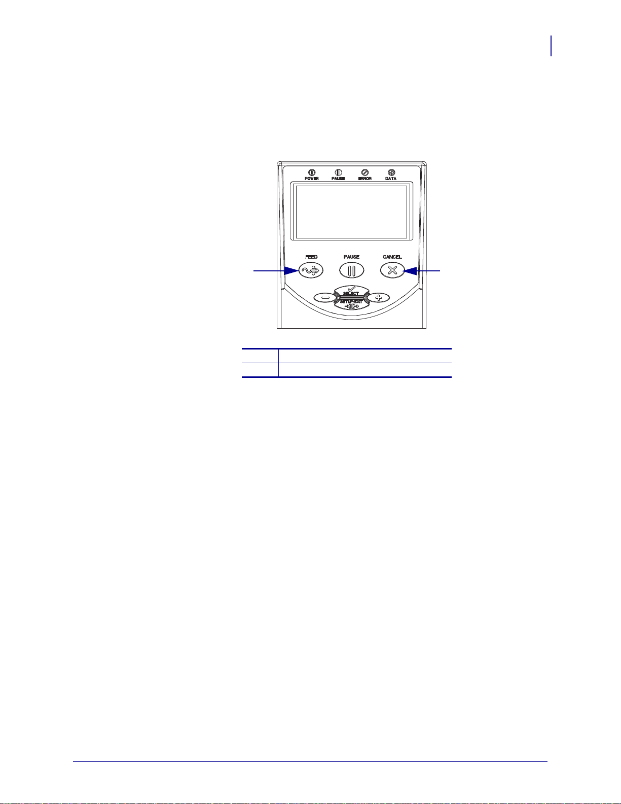
Illustration Callouts Callouts are used when an illustration contains information that needs
to be labeled and described. A table that contains the labels and descriptions follows the
graphic. Figure 1 provides an example.
Figure 1 • Sample Figure with Callouts
13
FEED button
1
CANCEL button
2
1/11/11 Z Series®/RZ™ Series User Guide 79695L-003
Page 14

About This Document
Notes • ___________________________________________________________________
__________________________________________________________________________
__________________________________________________________________________
__________________________________________________________________________
__________________________________________________________________________
__________________________________________________________________________
__________________________________________________________________________
__________________________________________________________________________
__________________________________________________________________________
__________________________________________________________________________
14
Document Conventions
79695L-003 Z Series®/RZ™ Series User Guide 1/11/11
Page 15

1
Introduction
This section shows the operational controls and location of major components used when
loading media.
Contents
External View. . . . . . . . . . . . . . . . . . . . . . . . . . . . . . . . . . . . . . . . . . . . . . . . . . . . . . . . . . 16
Printer Media Compartment. . . . . . . . . . . . . . . . . . . . . . . . . . . . . . . . . . . . . . . . . . . . . . . 18
Control Panel . . . . . . . . . . . . . . . . . . . . . . . . . . . . . . . . . . . . . . . . . . . . . . . . . . . . . . . . . . 19
Control Panel Buttons . . . . . . . . . . . . . . . . . . . . . . . . . . . . . . . . . . . . . . . . . . . . . . . . . 20
Control Panel Lights. . . . . . . . . . . . . . . . . . . . . . . . . . . . . . . . . . . . . . . . . . . . . . . . . . . 21
Printer Language Modes . . . . . . . . . . . . . . . . . . . . . . . . . . . . . . . . . . . . . . . . . . . . . . . . . 22
Firmware Downloads. . . . . . . . . . . . . . . . . . . . . . . . . . . . . . . . . . . . . . . . . . . . . . . . . . 22
Additional Printer Language Information . . . . . . . . . . . . . . . . . . . . . . . . . . . . . . . . . . . 22
1/11/11 Z Series®/RZ™ Series User Guide 79695L-003
Page 16
Introduction
1
2
16
External View
External View
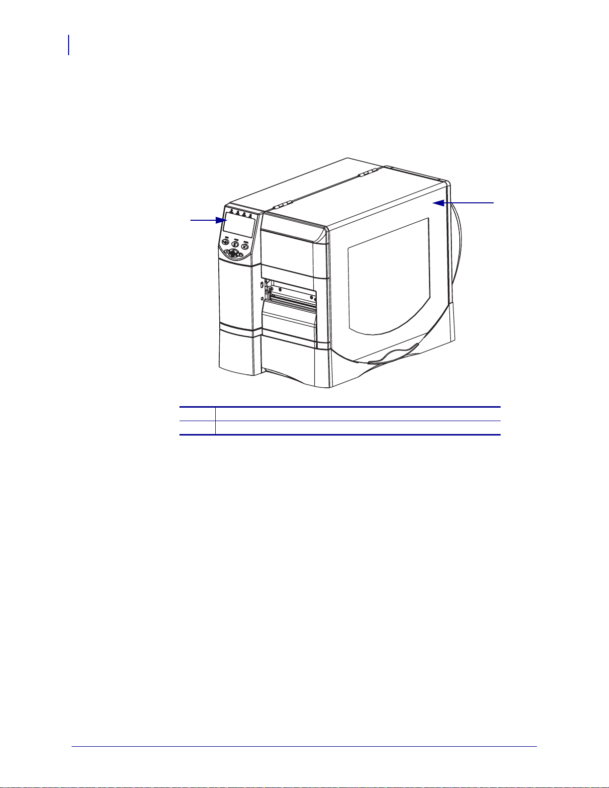
Figure 2 and Figure 3 show the components and connections on the outside of the printer.
Figure 2 • Front of Printer
Control panel
1
Media door
2
79695L-003 Z Series®/RZ™ Series User Guide 1/11/11
Page 17

Figure 3 • Rear of Printer
5
6
7
8
1
2
3
4
5
6
7
8
1
2
9
(All Standard Connectors, Internal 10/100 Wired Print Server,
and Wireless Print Server with Integrated Radio Shown)
(All Standard Connectors, Internal 10/100 Wired Print Server,
and Wireless Plus Print Server Shown)
Introduction
External View
17
Power switch (O = off, I = on)
1
AC power connector
2
5
6
Serial port
Internal wired print server port
(Ethernet option)
Wireless card ejector button
3
Wireless Plus print server card slot
4
(Ethernet option)
USB port
7
Parallel port
8
Antenna for wireless print server with
9
integrated radio (Ethernet option)
1/11/11 Z Series®/RZ™ Series User Guide 79695L-003
Page 18
Introduction
11
5
1
2
4
10
8
9
6
7
3
18
Printer Media Compartment
Printer Media Compartment
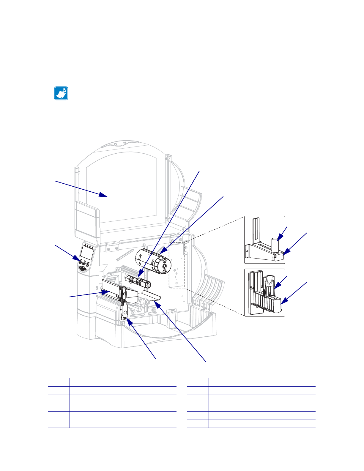
Figure 4 shows the components inside the media compartment of your printer. Depending on
installed options, your printer may look slig htly different.
Note • For optimal printing quality and proper printer performance across our product line,
Zebra strongly recommends the use of genuine Zebra™ supplies as part of the total solution.
Specifically, the ZM400, ZM600, RZ400, and RZ600 are designed to work only with
genuine Zebra™ printheads, thus maximizing safety and print quality.
Figure 4 • Printer Components
Printhead assembly
1
Control panel
2
Media door
3
Ribbon supply spindle
4
Ribbon take-up spindle
5
Media supply guide (newer models)
6
Media supply hanger (newer models)
7
Media supply guide (older models)
8
Media supply hanger (older models)
9
Dancer assembly
10
Printhead release latch
11
79695L-003 Z Series®/RZ™ Series User Guide 1/11/11
Page 19
Control Panel
1 2 3 4
5
6
7
8
11
12
10
9
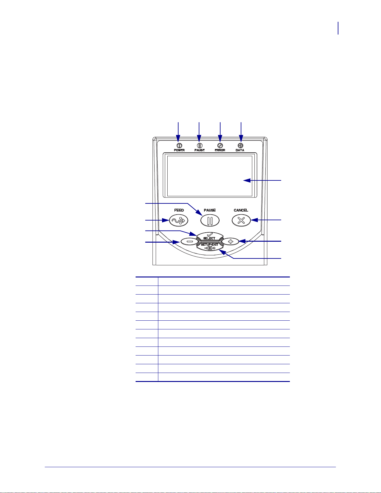
The control panel contains the ligh ts that indicate basic operatio n and the button s that you may
need to press during basic operation. The control panel buttons and lights are labeled in
Figure 5. Descriptions for each are located in Table 1 and Table 2.
Figure 5 • Control Panel
Introduction
Control Panel
19
Power LED
1
Pause LED
2
Error LED
3
Data LED
4
LCD
5
CANCEL button
6
PLUS (+) button
7
SETUP/EXIT button
1/11/11 Z Series®/RZ™ Series User Guide 79695L-003
8
MINUS (–) button
9
SELECT button
10
FEED button
11
PAUSE button
12
Page 20

Introduction
20
Control Panel
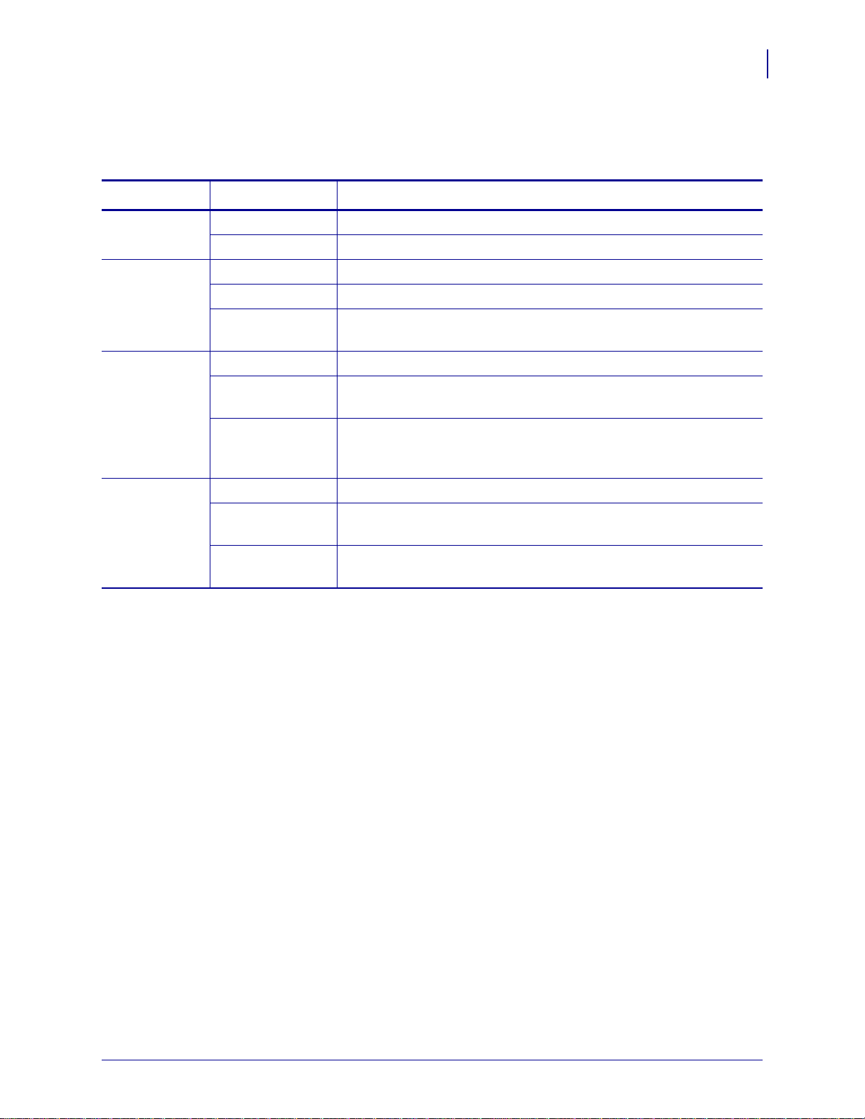
Control Panel Buttons
Button Function
Table 1 • Control Panel Buttons
FEED
PAUSE
CANCEL
SETUP/EXIT
SELECT
PLUS (+)
(scroll mode)
PLUS (+)
(change mode)
Forces the printer to feed one blank label each time the button is pressed.
• Printer not printing: one blank label immediately feeds.
• Printing: one blank label feeds after the current batch of labels is complete.
Starts and stops the printing process.
• Printer not printing: no printing occurs. (Press PAUSE again to resume printing.)
• Printing: printing stops after the current label is complete.
Cancels print jobs when the printer is paused.
• Printer not printing: the next stored label format does not print.
• Printing: current label completes printing, and the next label format is cancelled.
Press and hold for several seconds to cancel all print jobs in memory.
Enters and exits the configuration mode.
Toggles the function of PLUS (+) and MINUS (–) between the Scroll and Change
Modes.
• Press once to use PLUS (+) and MINUS (–) to change the values of the selection.
• Press again to use PLUS (+) and MINUS (–) to scroll through the menu items.
Scrolls to the next selection.
• Increases the value.
• Performs the action on the bottom right of the LCD.
MINUS (–)
(scroll mode)
MINUS (–)
(change mode)
Scrolls to the previous selection.
• Decreases the value.
• Moves to the next available digit in a number.
• Performs the action on the bottom left of the LCD.
79695L-003 Z Series®/RZ™ Series User Guide 1/11/11
Page 21
Control Panel Lights
Table 2 • Control Panel Lights
Light Status Indication
POWER Off The printer is off, or no power is applied.
On The printer is on.
PAUSE Off Normal printer operation.
On The printer has stopped all printing operations.
Flashing The Pause light flashes when initializing FLASH memory and in
Peel-Off Mode when the label is available.
ERROR Off Normal printer operation (no errors).
Introduction
Control Panel
21
On An error condition is preventing printing. This i ncludes
OUT
and RIBBON OUT errors.
Flashing An error condition exists, but printing is allowed to continue. This
includes
and
DATA Off Normal operation. No data being received or processed.
On The printer is processing data or is printing. No data is being
received.
Blinking quickly The printer is receiving data fro m or sending statu s information to the
host computer.
RIBBON IN warning, HEAD UNDER TEMP warning,
HEAD OVER TEMP error.
MEDIA
1/11/11 Z Series®/RZ™ Series User Guide 79695L-003
Page 22

Introduction
22
Printer Language Modes
Printer Language Modes
Depending on how your printer was ordered, it came from the factory with firmware that
operates in or allows you to use certain commands for one of the following printer languages:
• Zebra Programming Language (ZPL
®
•Eltron
Note • The following restrictions apply:
• EPL is supported only on 203 dpi printers.
• With older firmware, RFID functionality is available only with R53.X firmware, which
operates in ZPL mode with XML.
Firmware Downloads
You may download firmware to the printer at any time to change from one printer langua ge to
another. For the latest firmware versions and instructions for downloading them, go to
http://www.zebra.com/firmware.
Programming Language (EPL™)
®
), which includes XML
Note • When the printer changes from one printer language to another, error messages may
appear on the LCD, and some control panel lights may activate in error mode. You may
ignore these error messages and lights. When the firmware download is complete, reboot the
printer and then load printer defaults to return the printer to Operating mode.
Additional Printer Language Information
The following manuals contain specific information about the different printer language
modes. Copies of these manuals are o n the CD that came with your printer and at
http://www.zebra.com/manuals.
• Zebra Programming Guide for ZPL, ZBI, Set-Get-Do, Mirror, and WML
• EPL2™ Programming Guide
•
79695L-003 Z Series®/RZ™ Series User Guide 1/11/11
Page 23

2
Printer Setup
This section provides the tasks that you must complete and the issues that you must consider
before you load and configure your printer.
Contents
Before You Begin . . . . . . . . . . . . . . . . . . . . . . . . . . . . . . . . . . . . . . . . . . . . . . . . . . . . . . . 24
Handling the Printer . . . . . . . . . . . . . . . . . . . . . . . . . . . . . . . . . . . . . . . . . . . . . . . . . . . . . 25
Unpack and Inspect the Printer . . . . . . . . . . . . . . . . . . . . . . . . . . . . . . . . . . . . . . . . . . 25
Store the Printer. . . . . . . . . . . . . . . . . . . . . . . . . . . . . . . . . . . . . . . . . . . . . . . . . . . . . . 25
Ship the Printer . . . . . . . . . . . . . . . . . . . . . . . . . . . . . . . . . . . . . . . . . . . . . . . . . . . . . . 25
Select a Site for the Printer . . . . . . . . . . . . . . . . . . . . . . . . . . . . . . . . . . . . . . . . . . . . . . . 26
Select a Surface. . . . . . . . . . . . . . . . . . . . . . . . . . . . . . . . . . . . . . . . . . . . . . . . . . . . . . 26
Provide Proper Operating Conditions . . . . . . . . . . . . . . . . . . . . . . . . . . . . . . . . . . . . . 26
Allow Proper Space . . . . . . . . . . . . . . . . . . . . . . . . . . . . . . . . . . . . . . . . . . . . . . . . . . . 26
Provide a Data Source. . . . . . . . . . . . . . . . . . . . . . . . . . . . . . . . . . . . . . . . . . . . . . . . . 26
Provide a Power Source . . . . . . . . . . . . . . . . . . . . . . . . . . . . . . . . . . . . . . . . . . . . . . . 26
Select a Data Communication Interface. . . . . . . . . . . . . . . . . . . . . . . . . . . . . . . . . . . . . . 27
Data Cables and Wireless Cards. . . . . . . . . . . . . . . . . . . . . . . . . . . . . . . . . . . . . . . . . 31
Connect the Printer to a Power Source . . . . . . . . . . . . . . . . . . . . . . . . . . . . . . . . . . . . . . 32
Power Cord Specifications. . . . . . . . . . . . . . . . . . . . . . . . . . . . . . . . . . . . . . . . . . . . . . 33
Types of Media. . . . . . . . . . . . . . . . . . . . . . . . . . . . . . . . . . . . . . . . . . . . . . . . . . . . . . . . . 34
Ribbon Overview . . . . . . . . . . . . . . . . . . . . . . . . . . . . . . . . . . . . . . . . . . . . . . . . . . . . . . . 36
When to Use Ribbon . . . . . . . . . . . . . . . . . . . . . . . . . . . . . . . . . . . . . . . . . . . . . . . . . . 36
Coated Side of Ribbon. . . . . . . . . . . . . . . . . . . . . . . . . . . . . . . . . . . . . . . . . . . . . . . . . 36
1/11/11 Z Series®/RZ™ Series User Guide 79695L-003
Page 24

Printer Setup
24
Before You Begin
Before You Begin
Review this checklist, and resolve any issues before you set up or use your printer.
Unpack and Inspect the Printer Have you unpacked the printer and inspected it for
Select a Site Have you selected an appropriate location for the printer? If y ou have not,
Connect to a Data Source Have you determined how the printer will connect to a
Attach a Power Cord Do you have the correct power cord for your printer? If you are
Select Media Do you have the correct media for your application? If you are unsure,
Select Ribbon Do you need to use ribbon, and is the appropriate ribbon available, if
damage? If you have not, see Unpack and Inspect the Printer on page 25.
see Select a Site for the Printer on page 26.
data source (usually a computer)? For more information, see Select a Data
Communication Interface on page 27.
unsure, see Power Cord Specifications on page 33. To attach the power cord and connect
the printer to a power source, see Connect the Printer to a Power Source on page 32.
see Types of Media on page 34.
needed? If you are unsure, see Ribbon Overview on page 36.
79695L-003 Z Series®/RZ™ Series User Guide 1/11/11
Page 25
Handling the Printer
This section describes how to handle your printer.
Unpack and Inspect the Printer
When you receive the printer, immediately unpack it and inspect for shipping damage.
• Save all packing materials.
• Check all exterior surfaces for damage.
• Raise the media door, and inspect the media compartment for damage to components.
If you discover shipping damage upon inspection:
• Immediately notify the shipping company and file a damage report.
• Keep all packaging material for shipping company inspection.
• Notify your authorized Zebra reseller
Important • Zebra Technologies Corporation is not responsible for any damage incurred
during the shipment of the equipment and will not repair this damage under warranty.
Printer Setup
Handling the Printer
25
Store the Printer
If you are not placing the printer into immediate operation, repackage it using the original
packing materials. You may st ore the printer under the conditions shown in Table 3.
Temperature Relative Humidity
–40°F to 140°F (–40° to 60°C) 5% to 85% non-condensing
Ship the Printer
If you must ship the printer:
• Turn off (O) the printer, and disconnect all cables.
• Remove any media, ribbon, or loose objects from the printer interior.
• Close the printhead.
• Carefully pack the printer into the original container or a suitable alternate container to
avoid damage during transit. A shipping container can be purchased from Zebra if the
original packaging has been lost or destroyed.
Table 3 • Storage Temperature and Humidity
1/11/11 Z Series®/RZ™ Series User Guide 79695L-003
Page 26
Printer Setup
26
Select a Site for the Printer
Select a Site for the Printer
Consider the following whe n selecting an appropriate location for your printer.
Select a Surface
Select a solid, level surface of sufficient size and strength to accommodate the printer and
other equipment (such as a computer), if necessary. The choices include a table, countertop,
desk, or cart. For the printer’s weight and dimensions, see General Specifications on page 140.
Provide Proper Operating Conditions
This printer is designed to function in a wide range of environmental and electrical conditions,
including a warehouse or factory floor. For more information on the required conditions, see
General Specifications on page 140.
Table 4 shows the temperature and relative humidity requirements for the printer when it is
operating.
Table 4 • Operating Temperature and Humidity
Mode Temperature Relative Humidity
Thermal Transfer 40° to 105°F (5° to 40°C) 20 to 85% non-condensing.
Direct Thermal 32° to 105°F (0° to 40°C) 20 to 85% non-condensing
Allow Proper Space
The printer should have enough space around it for you to be able to open the media door. To
allow for proper ventilation and cooling, leave open space on all sides of the printer.
Caution • Do not place any padding or cushioning material behind or under the printer
because this restricts air flow and could cause the printer to overheat.
Provide a Data Source
If the printer will be located away from the data source (such as a computer), the selected site
must provide the appropriate connections to that data source. For more information on the
types of communication interfaces and their limitations, see Select a Data Communication
Interface on page 27.
Provide a Power Source
Place the printer within a short distance of a power outlet that is easily accessible.
79695L-003 Z Series®/RZ™ Series User Guide 1/11/11
Page 27
Select a Data Communication Interface
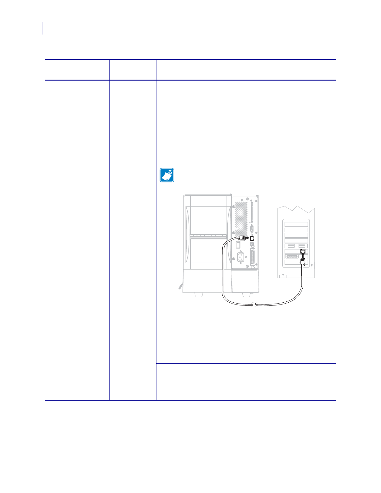
Table 5 provides basic information about data communication interfaces that you can use to
connect your printer to a comput er. Y ou may se nd label formats to the printer t hrough any data
communication interface that is available. Select an interface that is supported by both your
printer and your computer or your Local Area Network (LAN).
Table 5 also shows how to connect the different types of data cables to your printer and
computer. The connectors on the back of your computer may be in different locations than on
the sample computer shown in this section.
Caution • Ensure that the printer power is off (O) before connecting data communications
cables. Connecting a data communications cable while the power is on (
printer.
Table 5 • Data Communication Interfaces
Printer Setup
Select a Data Communication Interface
I) may damage the
27
Interface
Standard or
Optional
Description
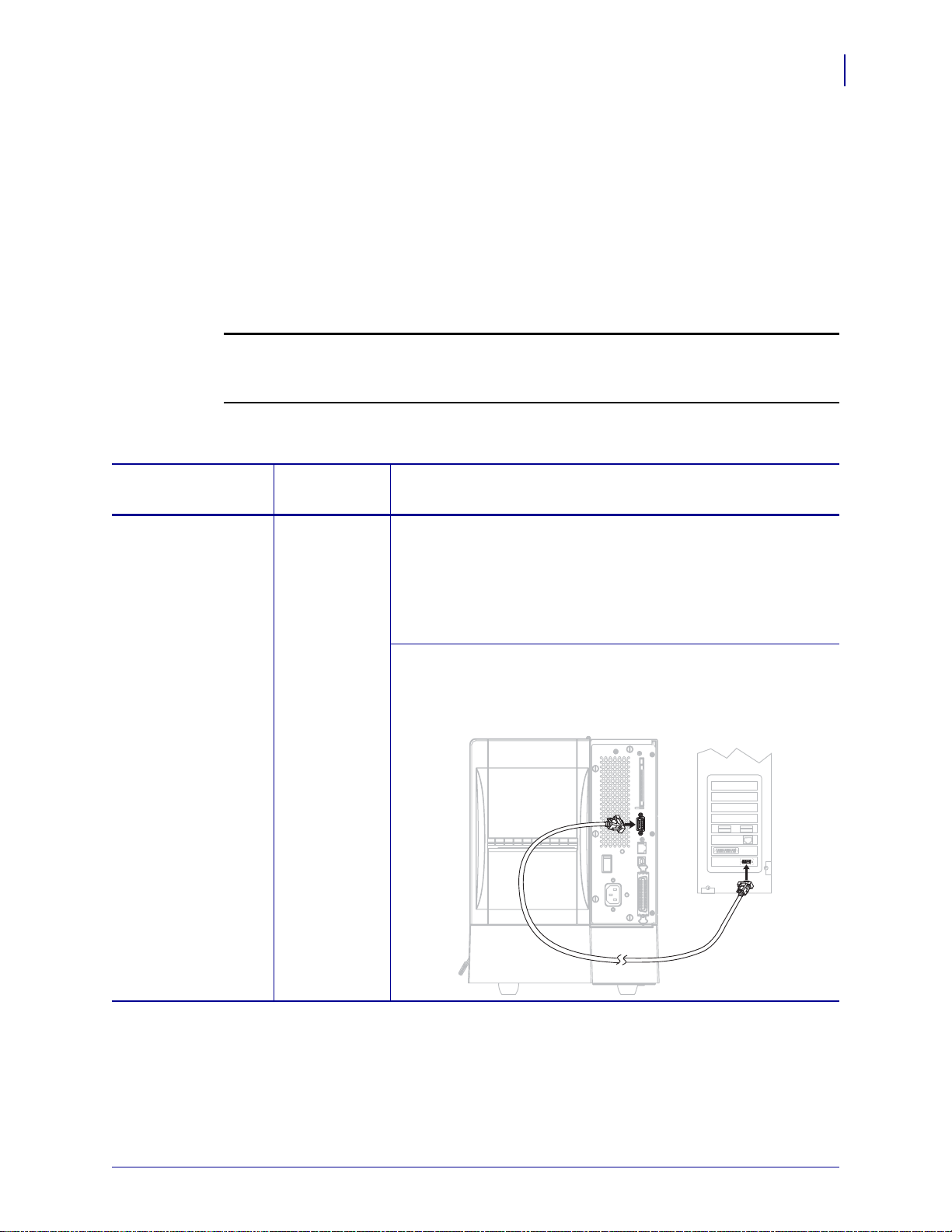
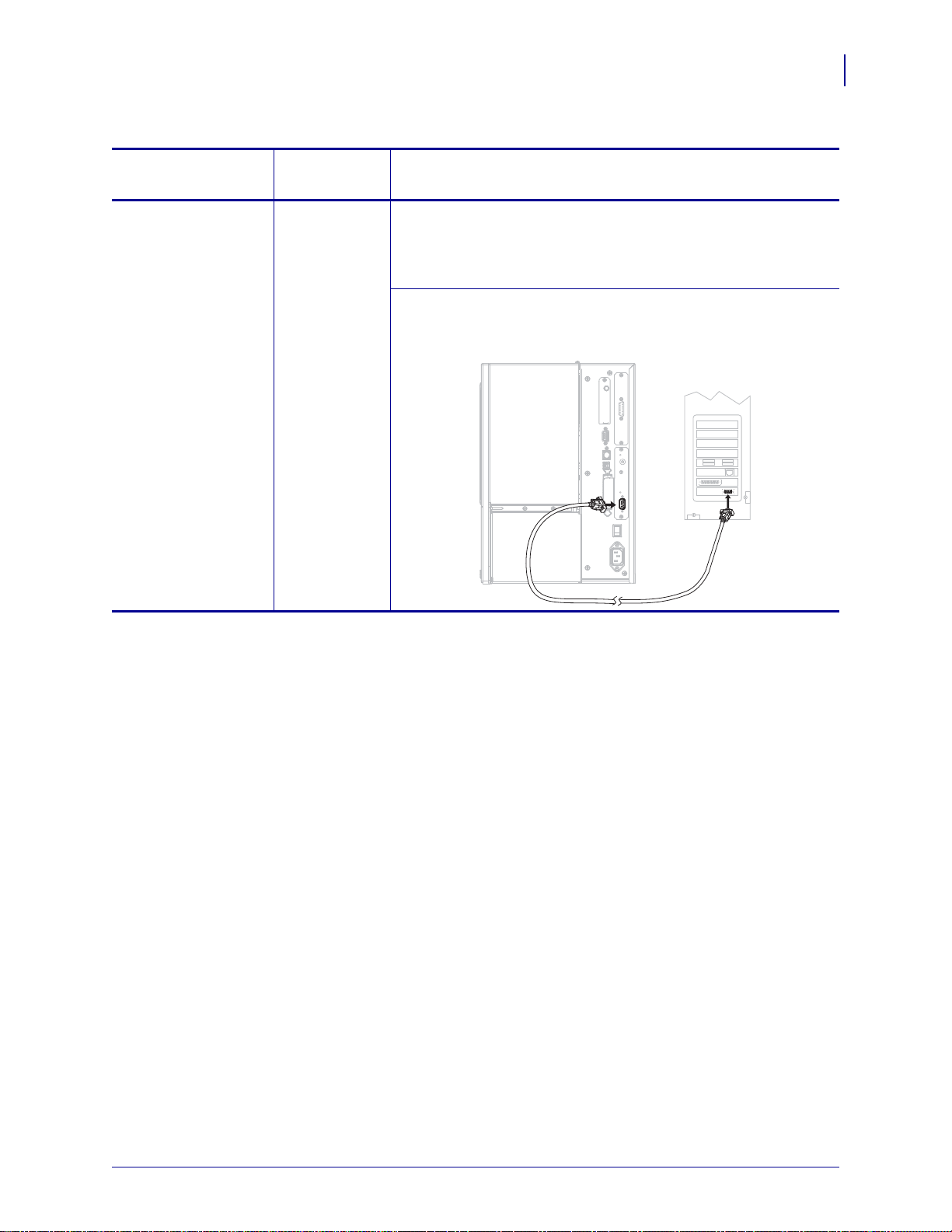
RS-232 Serial Standard Limitations and Requirements
• Maximum cable length of 50 ft (15.24 m).
• You may need to change printer parameters to match the host
computer.
• You need to use a null-modem adaptor to connect to the printer
if using a standard modem cable.
Connections and Configuration The baud rate, number of
data and stop bits, the parity, and the XON/XOFF or DTR control
must match those of the host computer. See Standard Control
Panel Parameters on page 73 to view or change these parameters.
1/11/11 Z Series®/RZ™ Series User Guide 79695L-003
Page 28
Printer Setup
28
Select a Data Communication Interface
Table 5 • Data Communication Interfaces (Continued)
Interface
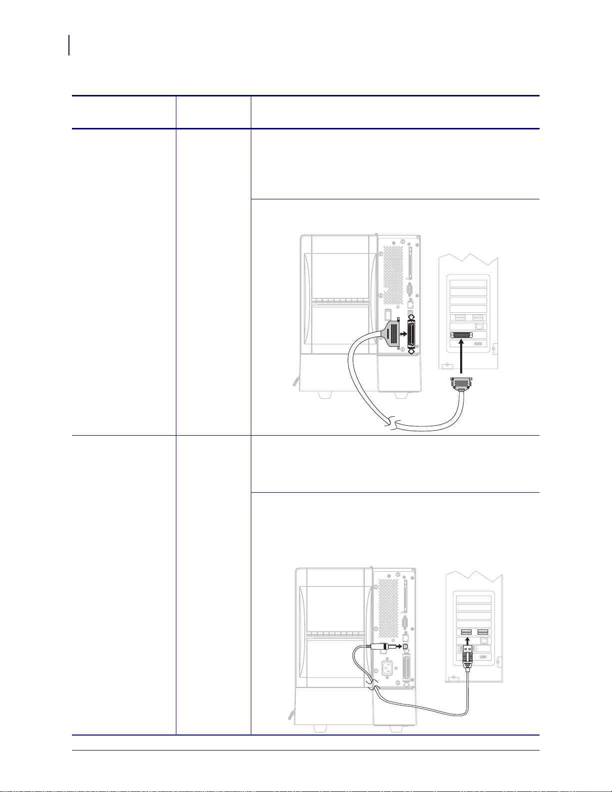
IEEE 1284
Bidirectional Parallel
Standard or
Optional
Description
Standard Limitations and Requirements
• Maximum cable length of 10 ft (3 m).
• Recommended cable length of 6 ft (1.83 m).
• No printer parameter changes required to match the host
computer.
Connections and Configuration No additional
configuration is necessary.
USB Standard Limitations and Requirements
• Maximum cable length of 16.4 ft (5 m).
• No printer parameter changes required to match the host
computer.
Connections and Configuration No additional
configuration is necessary.
Caution • Be careful not to plug the USB cable into the wired
Ethernet print server connector on the printer because doing so
will damage the connector.
79695L-003 Z Series®/RZ™ Series User Guide 1/11/11
Page 29
Select a Data Communication Interface
Table 5 • Data Communication Interfaces (Continued)
Printer Setup
29
Interface
Standard or
Optional
Description
Twinax/Coax Optional Limitations and Requirements
• Acts as an EBCDIC to ASCII converter.
• Allows for the ability to communicate with the printer in an
®
IBM
AS/400® environment.
Connections and Configuration No additional
configuration is necessary. To purchase this option, contact your
authorized Zebra reseller.
1/11/11 Z Series®/RZ™ Series User Guide 79695L-003
Page 30
Printer Setup
30
Select a Data Communication Interface
Table 5 • Data Communication Interfaces (Continued)
Interface
Internal wired
Ethernet print server
Standard or
Optional
Description
Optional Limitations and Requirements
• Can print to the printer from any computer on your LAN.
• Can communicate with the printer through the printer’s web
pages when in ZPL mode.
• The printer must be configured to use your LAN.
Connections and Configuration Refer to the ZebraNet
10/100 Print Server User and Reference Guide for configuration
instructions. A copy of this manual is available at
http://www.zebra.com/manuals or on the user CD that came with
your printer.
Note • To use this connection, you may need to remove a
factory-installed plug that is designed to keep someone
from accidentally plugging a USB connector into this port.
Wireless Ethernet
print server
Optional Limitations and Requirements
• Can print to the printer from any computer on your Wireless
Local Area Network (WLAN).
• Can communicate with the printer through the printer’s web
pages when in ZPL mode.
• The printer must be configured to use your WLAN.
Configuration Refer to the ZebraNet Wireless User Guide for
configuration instructions. A copy of this manual is available at
http://www.zebra.com/manuals or on the user CD that came with
your printer.
79695L-003 Z Series®/RZ™ Series User Guide 1/11/11
Page 31

Data Cables and Wireless Cards
You must supply all data cables or removeable radio cards for your application. (Some
wireless print servers come with an integrated radio card.)
Data Cables Ethernet cables do not require sh ielding, but all oth er data cabl es must be fully
shielded and fitted with metal or metallized connector shells. Unshielded data cables may
increase radiated emissions above the regulated limits.
To minimize electrical noise pickup in the cable:
• Keep data cables as short as possible.
• Do not bundle the data cables tightly with the power cords.
• Do not tie the data cables to power wire conduits.
Wireless Cards For supported wireless cards, refer to the ZebraNet Wireless User Guide. A
copy of the manual is available at http://www.zebra.com/manuals or on the user CD that came
with your printer.
Printer Setup
Select a Data Communication Interface
31
1/11/11 Z Series®/RZ™ Series User Guide 79695L-003
Page 32
Printer Setup
1
32
Connect the Printer to a Power Source
Connect the Printer to a Power Source
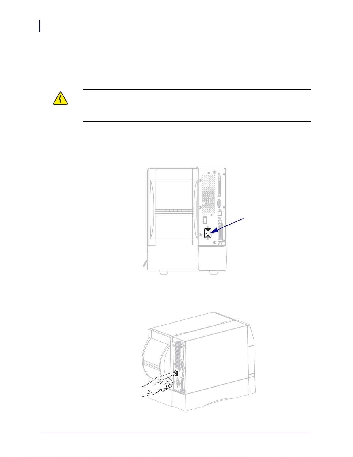
The AC power cord must have a three-prong female connector on one end that plugs into the
mating AC power connector at the rear of the printer. If a power cable was not included with
your printer, refer to Power Cord Specifications on page 33.
Caution • For personnel and equipment safety, always use an approved three-conductor
power cord specific to the region or country intended for installation. This cord must use an
IEC 320 female connector and the appropriate region-specific three-conductor grounded
plug configuration.
To connect the printer to a power source, complete these steps:
1. Toggle the printer power switch to the off (O) position.
2. Plug the power cord into the AC power connector (1) on the rear of the printer.
3. Plug the other end of the power cord into a power outlet near the printer.
4. Turn o n ( I) the printer.
The control panel LCD and lights activate, indicating that the printer is booting up.
79695L-003 Z Series®/RZ™ Series User Guide 1/11/11
Page 33
Power Cord Specifications
3
1
2
4
Caution • For personnel and equipment safety, always use an approved three-conductor
power cord specific to the region or country intended for installation. This cord must use an
IEC 320 female connector and the appropriate region-specific, three-conductor grounded
plug configuration.
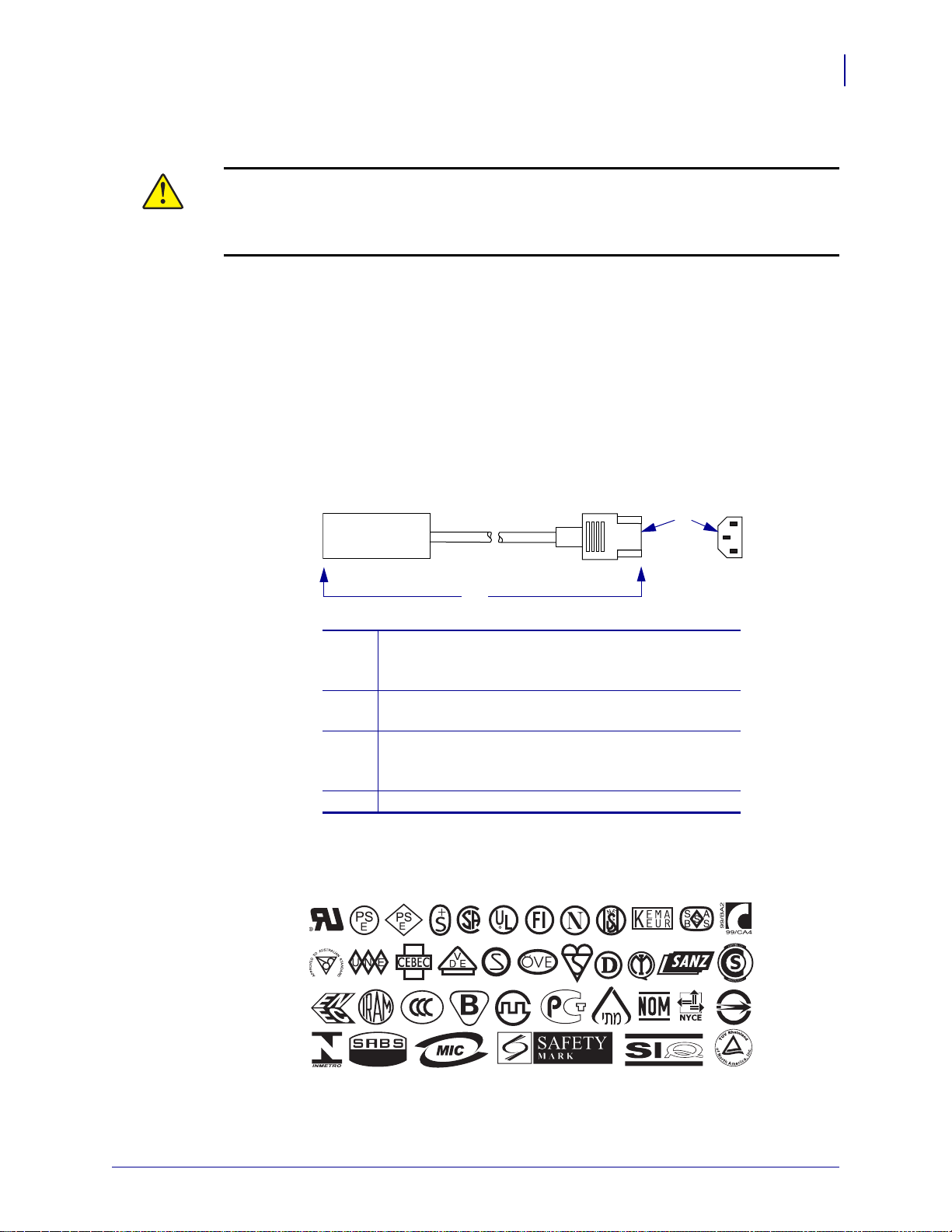
Depending on how your printer was ordered, a power cord may or may not be included. If one
is not included or if the one included is not suitable for your requirements, see Figure 6 and
refer to the following guidelines:
• The overall cord length must be less than 9.8 ft. (3 m).
• The cord must be rated for at least 10 A, 250 V.
• The chassis ground (earth) must be connected t o ensure safety and redu ce electromagnetic
interference.
Figure 6 • Power Cord Specifications
Printer Setup
Connect the Printer to a Power Source
33
AC power plug for your country—This should bear
1
the certification mark of at least one of the known
international safety organizations (Figure 7).
3-conductor HAR cable or other cable approved for
2
your country.
IEC 320 connector—This should bear the
3
certification mark of at least one of the known
international safety organizations (Figure 7).
Length 9.8 ft. (3 m). Rating 10 Amp, 250 VAC.
4
Figure 7 • International Safety Organization Certifications
1/11/11 Z Series®/RZ™ Series User Guide 79695L-003
Page 34

Printer Setup
34
Types of Media
Types of Media
Important • Zebra strongly recommends the use of Zebra-brand supplies for continuous
high-quality printing. A wide range of paper, polypropylene, polyester, and vinyl stock has
been specifically engineered to enhanc e the print ing c apabi lities of the p rinter an d to pre vent
premature printhead wear. To purchase supplies, go to http://www.zebra.com/howtobuy.
Your printer can use various types of media:
• Standard media—Most standard media uses an adhesive backing that stic ks individual
labels or a continuous length of labels to a liner.
• Tag st ock—Tags are usually made from a heavy paper. Tag stock does not have adhesive
or a liner, and it is typically perforated between tags.
• Radio frequency identification (RFID) “smart” media—RFID
media can be used in a printer that is equipped with an RFID
reader/encoder. RFID la bels are made from the same materi als and
adhesives as non-RFID labels. Each label has an RFID transpon der
(sometimes called an “inlay”), made of a chip and an antenna,
embedded between the label and the liner. The shape of the transponder varies by
manufacturer and is visible through the label. All “smart” labels have memory that can be
read, and many have memory that can be encoded.
Important • Trans ponder placement within a label depends on the transponder type and
the printer model. Make sure that you are using the correct “smart ” media for your pri nter.
For more information, refer to the RFID Programming Guide. A copy is available at
http://www.zebra.com/manuals or on the user CD that came with your printer.
Table 6 describes roll and fanfold media. Roll media is loaded into the printer while fanfold
media may be located inside or outside of the printer.
79695L-003 Z Series®/RZ™ Series User Guide 1/11/11
Page 35
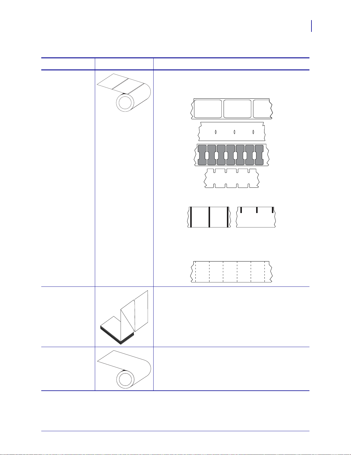
Table 6 • Roll and Fanfold Media
Media Type How It Looks Description
Printer Setup
Types of Media
35
Non-Continuous
Roll Media
Roll media is wound on a 3-in. (76-mm) core. Individual
labels are separated by one or more of the following methods:
• Web media separates labels by gaps, holes, or notches.
• Black mark media uses pre-printed black marks on the
back side of the media to indicate label separations.
• Perforated media has perforations that allow the labels or
tags to be separated from each other easily. The media may
also have black marks or other separations between labels
or tags.
Non-Continuous
Fanfold Media
Fanfold media is folded in a zigzag pattern. Fanfold media can
have the same label separations as non-continuous roll media.
The separations would fall on or near the folds.
Continuous
Roll Media
Roll media is wound on a 3-in. (76-mm) core.
Continuous roll media does not have gaps, holes, notches , o r
black marks to indicate label separations. This allows the
image to be printed anywhere on the label. Sometimes a cutter
is used to cut apart individual labels.
1/11/11 Z Series®/RZ™ Series User Guide 79695L-003
Page 36

Printer Setup
36
Ribbon Overview
Ribbon Overview
Ribbon is a thin film that is coated on one side with wax, resin, or wax resin, which is
transferred to the media during the thermal transfer process. The media determines whether
you need to use ribbon and how wide the ribbon must be.
When ribbon is used, it must be as wide as or wider than the media being used. If the ribbon is
narrower than the media, areas of the printhead are unprotected and subject to premature wear.
When to Use Ribbon
Thermal transfer media requires ribbon for printing while direct thermal media does not.
To determine if ribbon must be used with a particular media, perform a media scratch test.
To perform a media scratch test, complete these steps:
1. Scratch the print surface of the media rapidly with your fingernail.
2. Did a black mark appear on the media?
If a black mark... Then the media is...
Does not appear on the media Thermal transfer. A ribbon is required.
Appears on the media Direct thermal. No ribbon is required.
Coated Side of Ribbon
Ribbon can be wound with the coated side on the inside or outside. The ribbon used must
match the Thermal Transfer option installed. The standard Thermal Transfer option (black
ribbon spindle) uses ribbon coated on the outside, and the alternate Thermal Transfer option
(gray ribbon spindle, available on the ZM400 and RZ400 only) uses ribbon coated on the
inside. If you are unsure which side of a particular roll of ribbon is coated, perform an adhesive
test or a ribbon scratch test to determine which side is coated.
Adhesive Test
If you have labels available, perform the adhesive test to determine which side of a ribbon is
coated. This method works well for ribbon that is already installed.
To perform an adhesive test, complete these steps:
1. Peel a label from its liner.
2. Press a corner of the sticky side of the label to the outer surface of the roll of ribbon.
3. Peel the label off of the ribbon.
79695L-003 Z Series®/RZ™ Series User Guide 1/11/11
Page 37

4. Observe the results. Did flakes or particles of ink from the ribbon adhere to the label?
If ink from the ribbon... Then...
Adhered to the label The ribbon is coated on the outside and can be
used with the standard Thermal Transfer
option (black ribbon spindle). In the ribbon
loading procedure, instructions are marked
with this symbol.
Did not adhere to the label The ribbon is coated on the inside and can be
used with the alternate Thermal Transfer
option (gray ribbon spindle). In the ribbon
loading procedure, instructions are marked
with this symbol.
Ribbon Scratch Test
Perform the ribbon scratch test when labels are unavailable.
To perform a ribbon scratch test, complete these steps:
Printer Setup
Ribbon Overview
37
1. Unroll a short length of ribbon.
2. Place the unrolled section of ribbon on a piece of paper with the outer surface of the
ribbon in contact with the paper.
3. Scratch the inner surface of the unrolled ribbon with your fingernail.
4. Lift the ribbon from the paper.
5. Observe the results. Did the ribbon leave a mark on the paper?
If the ribbon... Then...
Left a mark on the paper The ribbon is coated on the outside and can be used with
the standard Thermal Transfer option (black ribbon
spindle).
Did not leave a mark on the
paper
The ribbon is coated on the inside and can be
used with the alternate Thermal Transfer
option (gray ribbon spindle). In the ribbon
loading procedure, instructions are marked
with this symbol.
1/11/11 Z Series®/RZ™ Series User Guide 79695L-003
Page 38

Printer Setup
Notes • ___________________________________________________________________
__________________________________________________________________________
__________________________________________________________________________
__________________________________________________________________________
__________________________________________________________________________
__________________________________________________________________________
__________________________________________________________________________
__________________________________________________________________________
__________________________________________________________________________
__________________________________________________________________________
38
Ribbon Overview
79695L-003 Z Series®/RZ™ Series User Guide 1/11/11
Page 39

3
Operations
This section provides the procedures for loading and calibrating th e pri nt er.
Note • Complete the tasks and resolve the issues in Printer Setup on page 23 before
operating the printer.
Contents
Print Modes and Printer Options . . . . . . . . . . . . . . . . . . . . . . . . . . . . . . . . . . . . . . . . . . . 40
Print Mode Descriptions and Printer Requirements. . . . . . . . . . . . . . . . . . . . . . . . . . . 40
Media Paths. . . . . . . . . . . . . . . . . . . . . . . . . . . . . . . . . . . . . . . . . . . . . . . . . . . . . . . . . 41
Load Media . . . . . . . . . . . . . . . . . . . . . . . . . . . . . . . . . . . . . . . . . . . . . . . . . . . . . . . . . . . 43
Beginning Steps for all Print Modes and Printer Options. . . . . . . . . . . . . . . . . . . . . . . 43
Additional Steps for Tear-Off Mode . . . . . . . . . . . . . . . . . . . . . . . . . . . . . . . . . . . . . . . 47
Additional Steps for Peel-Off Mode (with or without Liner Take-Up) . . . . . . . . . . . . . . 48
Additional Steps for Cutter or Delayed Cut Mode . . . . . . . . . . . . . . . . . . . . . . . . . . . . 53
Additional Steps for Rewind Mode. . . . . . . . . . . . . . . . . . . . . . . . . . . . . . . . . . . . . . . . 54
Load Ribbon. . . . . . . . . . . . . . . . . . . . . . . . . . . . . . . . . . . . . . . . . . . . . . . . . . . . . . . . . . . 58
Remove Used Ribbon . . . . . . . . . . . . . . . . . . . . . . . . . . . . . . . . . . . . . . . . . . . . . . . . . 62
Calibrate the Printer. . . . . . . . . . . . . . . . . . . . . . . . . . . . . . . . . . . . . . . . . . . . . . . . . . . . . 63
Auto Calibration . . . . . . . . . . . . . . . . . . . . . . . . . . . . . . . . . . . . . . . . . . . . . . . . . . . . . . 63
Manual Calibration. . . . . . . . . . . . . . . . . . . . . . . . . . . . . . . . . . . . . . . . . . . . . . . . . . . . 63
Adjust Printhead Pressure . . . . . . . . . . . . . . . . . . . . . . . . . . . . . . . . . . . . . . . . . . . . . . . . 64
1/11/11 Z Series®/RZ™ Series User Guide 79695L-003
Page 40
Operations
40
Print Modes and Printer Options
Print Modes and Printer Options
The printer can use different print modes and options for label removal (Table 7). Use a print
mode that matches the media being used and the printer options available. For more
information on the types of media, see Types of Media on page 34. To select a print mode, see
Select Print Mode on page 76.
Print Mode Descriptions and Printer Requirements
Table 7 • Print Modes and Printer Options
Print Mode When to Use/Printer Options Required Printer Actions
Tear-Off
(default setting)
Peel-Off Use only if the printer has the Peel-Off,
Cutter Use if the printer has a cutter option when
Delayed Cut Use if the printer has a cutter option when
Rewind Use if the printer has the Rewind option and
RFID Use when printing RFID labels with
Use for most applications. This mode can
be used with any printer options and most
media types.
Liner Take-Up, or Rewind option.
you want the labels to be cut apart.
you want the printer to cut the labels apart
at a signal.
you want the labels to rewind on a core.
RZ Series printers or with Z Series printers
that have an optional RFID reader/encoder
installed.
The printer prints label formats as it
receives them. The printer operator can tear
off the printed labels any time after they
print.
The printer peels the label from the liner
during printing and then pauses until the
label is removed.
In Peel-Off mode, the liner exits the front of
the printer. In Peel-Off mode with Liner
Take-Up, the liner winds onto the liner
take-up spindle or the rewind spindle.
The printer prints a label and then cuts it
free.
The printer prints a label, pauses, and cuts
the label when it receives the ~JK (delayed
cut) ZPL command.
The printer prints without pausing between
labels. The media or liner is wound onto a
core after printing.
The printer increases throughput time when
printing batches of RFID labels by
eliminating backfeed between labels
Linerless Peel Reserved for future options. Reserved for future options.
Linerless
Rewind
Linerless Tear Reserved for future options. Reserved for future options.
79695L-003 Z Series®/RZ™ Series User Guide 1/11/11
Reserved for future options. Reserved for future options.
Page 41
Media Paths
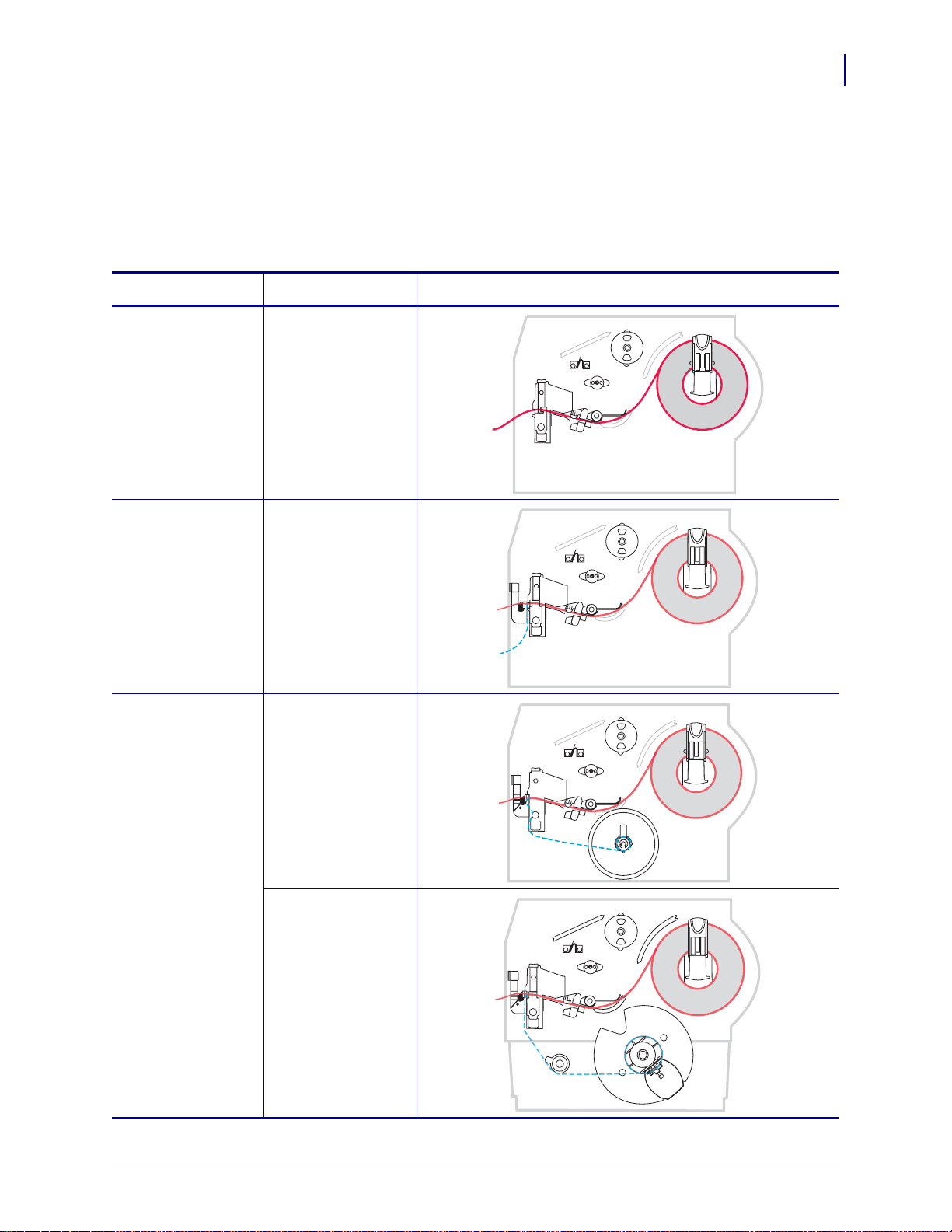
Table 8 shows the media paths for print mode and printer option combinations using roll
media. Fanfold media uses the same print modes and printer options as roll media. RFID
printers can use all of these printer options and have the same media paths.
Table 8 • Media Paths for Print Modes with Various Printer Options
Operations
Print Modes and Printer Options
41
Print Mode Printer Option
Tear-Off Printers with any
printer options can
use Tear-Off mode
Peel-Off Peel, Liner take-up,
or Rewind
Peel-Off (with Liner
Liner take-up
Take-Up)
Media Path
Rewind
Red solid lines = media, Blue dotted lines = backing only
1/11/11 Z Series®/RZ™ Series User Guide 79695L-003
Page 42

Operations
42
Print Modes and Printer Options
Table 8 • Media Paths for Print Modes with Various Printer Options (Continued)
Print Mode Printer Option
Cutter or
Delayed Cut
Cutter (shown with
an optional catch
tray)
Rewind Rewind
Media Path
Red solid lines = media, Blue dotted lines = backing only
79695L-003 Z Series®/RZ™ Series User Guide 1/11/11
Page 43
Load Media
The beginning steps for loading media apply to all printers, including those that have the
peel-off, liner take-up, cutter, or rewind option. When you have completed these beginning
steps, continue with the media loading instructions for the print mode and printer options that
apply to you. For more information about print modes and printer options, see Print Modes
and Printer Options on page 40.
Caution • While performing any tasks near an open printhead, remove all rings, watches,
hanging necklaces, identification badges, or other metallic objects that could touch the
printhead. You are not required to turn off the printer power when working near an open
printhead, but Zebra recommends it as a precaution. If you turn off the power, you will lose
all temporary settings, such as label formats, and you must reload them before you resume
printing.
Beginning Steps for all Print Modes and Printer Options
To begin loading media for all print modes and printer options, complete these
steps:
Operations
Load Media
43
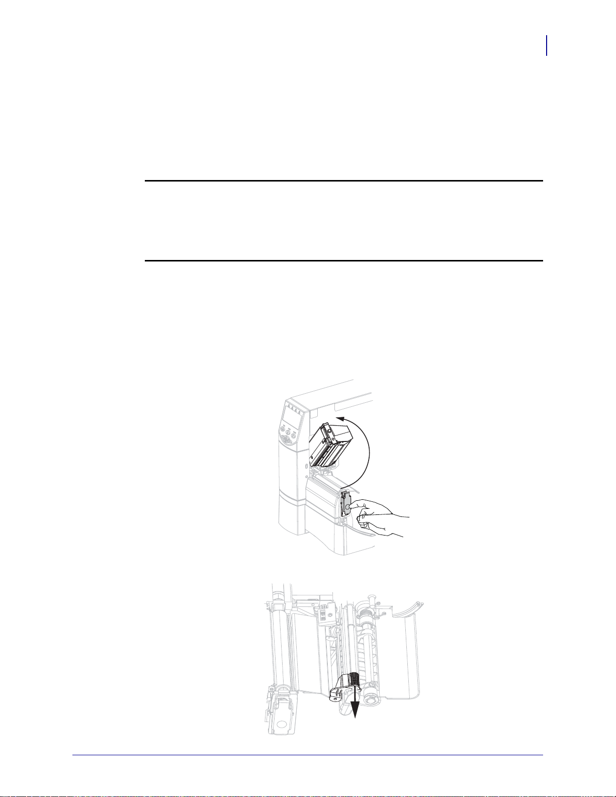
1. Press the printhead release latch to open the prin th ead assemb ly. Lift the printhead until it
latches open.
2. Slide out the media guide.
1/11/11 Z Series®/RZ™ Series User Guide 79695L-003
Page 44

44
Operations
Load Media
3. Insert media into the printer. Follow the instructions for roll or fanfold media, as
appropriate.
Roll Media
a. Remove and discard any tags or
labels that are dirty or that are held by
adhesives or tape.
b. Pull out and, if applicable, flip down
the media supply guide.
Fanfold Media
a. Pull out and, if applicable, flip down
the media supply guide.
b. Feed the media through the rear or
bottom access slot.
Rear Feed
Bottom Feed
79695L-003 Z Series®/RZ™ Series User Guide 1/11/11
Page 45

Operations
Load Media
45
Roll Media (Continued)
c. Place the roll of media on the media
supply hanger. Push the roll as far
back as it will go.
Fanfold Media (Continued)
c. Drape the media over the media
supply hanger.
d. If applicable, flip up the media supply
guide.
d. If applicable, flip up the media supply
guide.
1/11/11 Z Series®/RZ™ Series User Guide 79695L-003
Page 46

46
13 2
Operations
Load Media
Roll Media (Continued)
e. Slide in the media supply guide until
it touches the edge of the roll.
Fanfold Media (Continued)
e. Slide in the media supply guide until
it touches the edge of the media.
4. Feed the media under the dancer assembly ( 1), the uppe r media sen sor (2), and t he ri bbon
sensor (
3). Slide the media back until it touches the inside back wall of the upper media
sensor.
5. Continue with the final instructions for the desired print mode. The print mode must be
compatible with the media being used and the printer options installed. See Print Mode
Descriptions and Printer Requirements on page 40 for more information.
• Additional Steps for Tear-Off Mode on page 47
• Additional Steps for Peel-Off Mode (with or without Liner Take-Up) on page 48
• Additional Steps for Cutter or Delayed Cut Mode on page 53
• Additional Steps for Rewind Mode on page 54
79695L-003 Z Series®/RZ™ Series User Guide 1/11/11
Page 47

Additional Steps for Tear-Off Mode
After completing Beginning Steps for all Print Modes and Printer Options on page 43,
continue with this section to operate the printer in Tear-Off mode.
To operate the printer in Tear-Off mode, complete these steps:
1. Slide in the media guide until it touches the outer edge of the media.
Operations
Load Media
47
2. Set the printer to Tear-Off mode. See Select Print Mode on page 76 for instructions.
3. Close the printhead assembly.
4. If the printer is paused (the Pause light is on), press PAUSE to enable printing.
1/11/11 Z Series®/RZ™ Series User Guide 79695L-003
Page 48
48
Operations
Load Media
Additional Steps for Peel-Off Mode (with or without Liner Take-Up)
After completing Beginning Steps for all Print Modes and Printer Options on page 43,
continue with this section to operate the printer in Peel-Of f mode with or without liner take-u p.
Your printer must have the Peel option , the Liner Ta ke-Up option, or the Rewind option
installed. See Print Modes and Printer Options on page 40 for more information.
For additional procedures related to the rewind option, see Routine Maintenance for the
Rewind Option on page 108.
To operate the printer in Peel-Off mode, complete these steps:
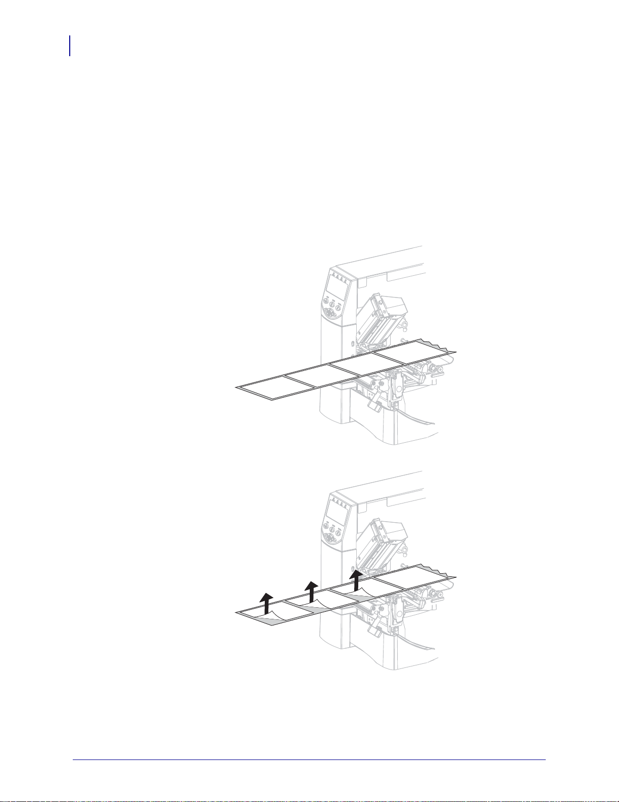
1. Extend the media approximately 18 in. (500 mm) out of the printer.
2. Remove the exposed labels so that only the liner remains.
79695L-003 Z Series®/RZ™ Series User Guide 1/11/11
Page 49

Operations
1
2
1
1
Load Media
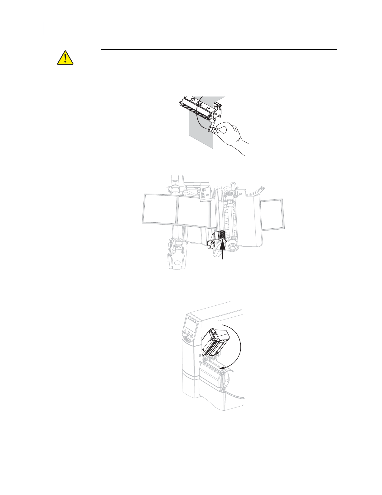
3. Push down the peel-off mechanism release lever to open the peel assembly.
4. Feed the liner over the tear-off/peel-off bar (1) and behind the peel assembly (2). Make
sure that the end of the liner falls outside of the printer.
49
5. Complete this step only if you want to use Peel-Off mode with liner take-up. Your printer
must have the Liner Take-Up option or the Rewind option installed. Follow the
instructions for your printer option.
Rewind Option Liner Take-Up Option
a. Feed the liner under the media
alignment roller (
1).
a. Slide the liner into the slot in the liner
take-up spindle (
1).
1/11/11 Z Series®/RZ™ Series User Guide 79695L-003
Page 50
50
Operations
Load Media
Rewind Option (Continued) Liner Take-Up Option (Continued)
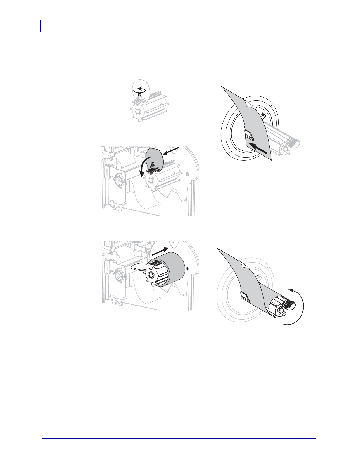
b. Loosen the thumbscrew on the rewind
media guide.
c. Slide the rewind media guide all the
way out, and then fold it down.
d. Slide an empty core onto the rewind
spindle.
b. Push the liner back until it touches the
back plate of the liner take-up spindle
assembly.
c. Wrap the liner around the liner
take-up spindle and turn the spindle
counterclockwise to tighten the liner.
79695L-003 Z Series®/RZ™ Series User Guide 1/11/11
Page 51

Operations
Load Media
Rewind Option (Continued) Liner Take-Up Option (Continued)
51
e. Wrap the liner around the core and
turn the rewind spindle
counterclockwise to tighten the liner.
f. Fold up the rewind media guide, and
then slide it in until it touches the
liner.
(No additional steps for the liner take-up
option.)
g. Tighten the thumbsc re w on the
rewind media guide.
1/11/11 Z Series®/RZ™ Series User Guide 79695L-003
Page 52
52
Operations
Load Media
6.
Caution • Use the peel release lever and your right hand to close the peel assembly.
Do not use your left hand to assist in closing. The top edge of the peel roller/assembly
could pinch your fingers.
Close the peel assembly using the peel-off mechanism release lever.
Slide in the media guide until it touches the outer edge of the media.
7.
8. Set the printer to Peel-Off mode. See Select Print Mode on page 76 for instructions.
9. Close the printhead assembly.
10. If the printer is paused (the Pause light is on), press PAUSE to enable printing. Peeling and
liner take-up (if used) begin automatically.
79695L-003 Z Series®/RZ™ Series User Guide 1/11/11
Page 53

Additional Steps for Cutter or Delayed Cut Mode
1
After completing Beginning Steps for all Print Modes and Printer Options on page 43,
continue with this section to operate the printer in Cutter or Delayed Cut mode.
To operate the printer in Cutter or Delayed Cut mode, complete these steps:
1.
Caution • The cutter blade is sharp. Do not touch or rub the blade with your fingers.
Feed the media through the cutter (1).
Operations
Load Media
53
Slide in the media guide until it touches the outer edge of the media.
2.
3. Set the printer to Cutter or Delayed Cut mode. See Select Print Mode on page 76 for
instructions.
1/11/11 Z Series®/RZ™ Series User Guide 79695L-003
Page 54

54
Operations
Load Media
4. Close the printhead assembly.
5. If the printer is paused (the Pause light is on), press PAUSE to enable printing. Cutting
begins automatically.
Additional Steps for Rewind Mode
After completing Beginning Steps for all Print Modes and Printer Options on page 4 3,
continue with this section to operate the printer in Rewind mode. For additional procedures
related to the rewind option, see Routine Maintenance for the Rewind Option on page 10 8.
To operate the printer in Rewind mode, complete these steps:
1. Pull approximately 18 in. (500 mm) of media through the front of the pr inter.
79695L-003 Z Series®/RZ™ Series User Guide 1/11/11
Page 55
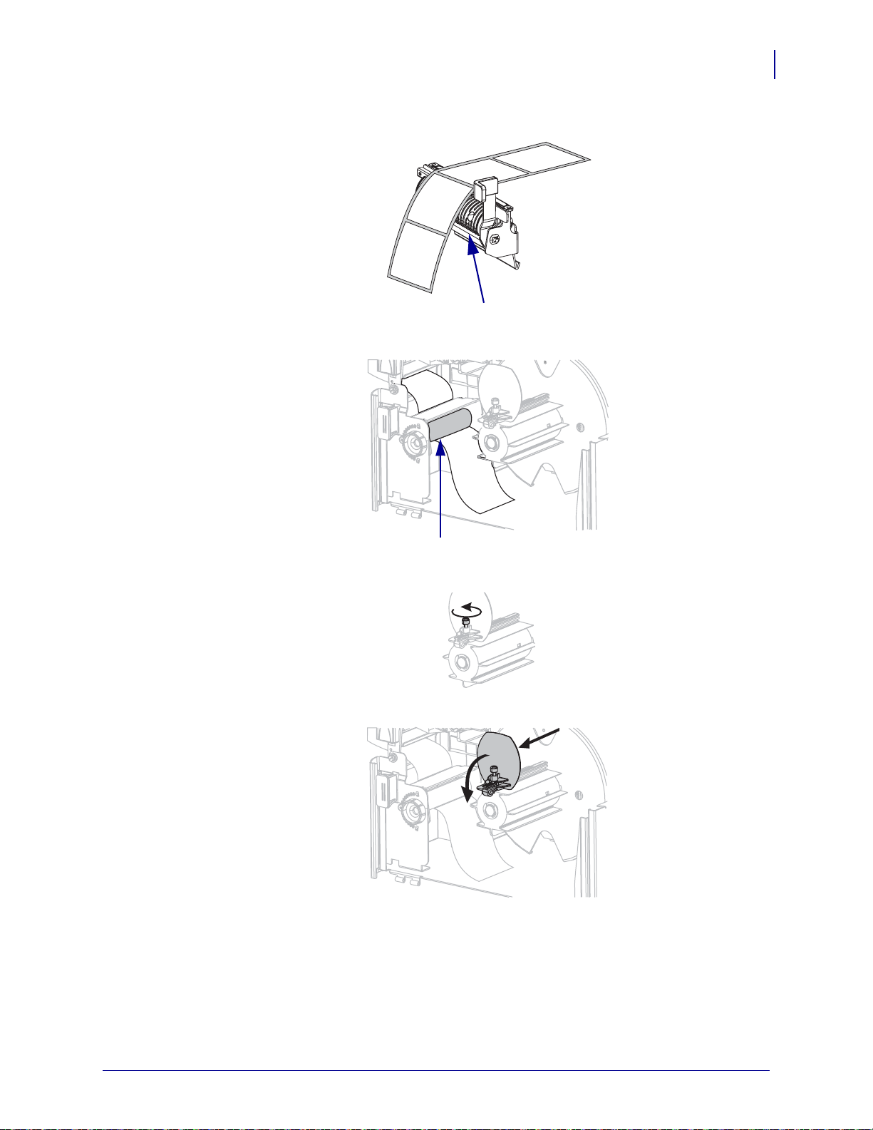
2. Feed the media over the peel assembly (1).
1
1
3. Feed the media under the media alignment roller (1).
Operations
Load Media
55
4. Loosen the thumbscrew on the rewind media guide.
5. Slide the rewind media guide all the way out, and then fold it down.
1/11/11 Z Series®/RZ™ Series User Guide 79695L-003
Page 56
56
Operations
Load Media
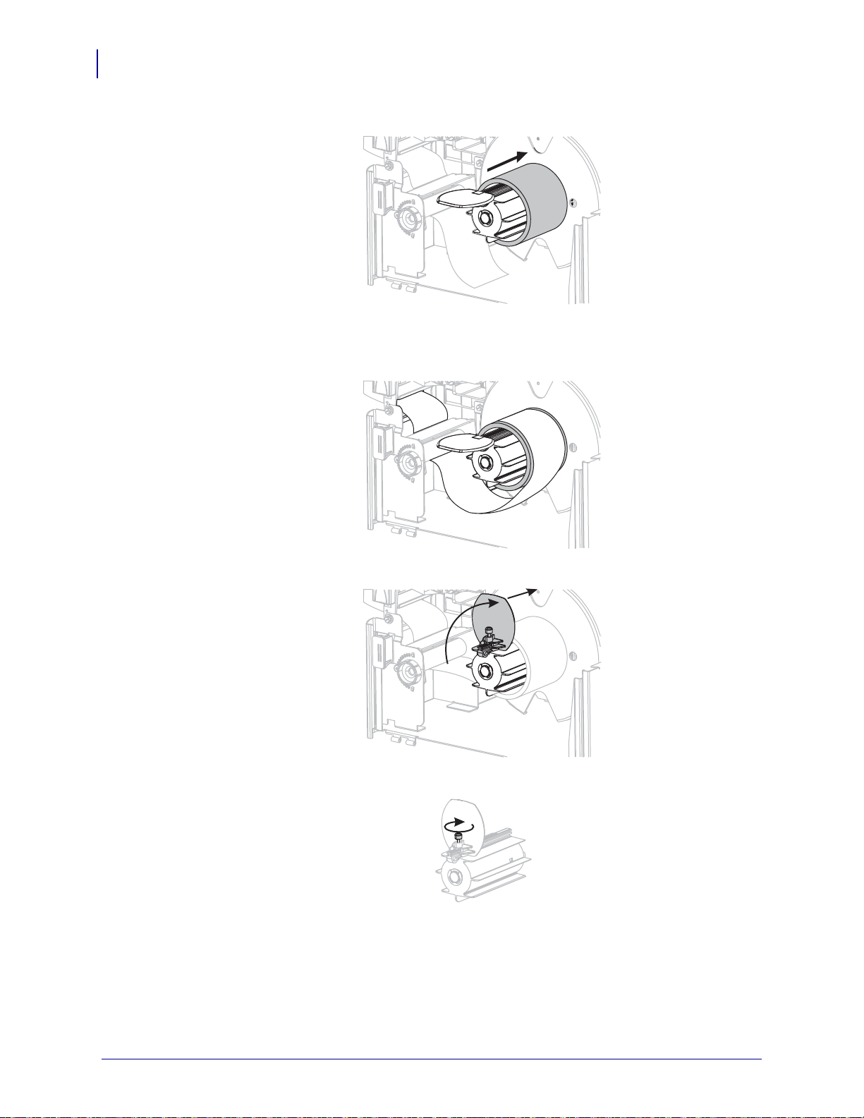
6. Slide an empty core onto the rewind spindle.
7. Wrap the media around the core and turn the rewind spindle counterclockwise to tighten
the media. Ensure that the edge of the media is flush against the backplate of the rewind
spindle.
8. Fold up the rewind media guide, and then slide it in until it touches the media.
9. Tighten the thumbscrew on the rewind media guide.
79695L-003 Z Series®/RZ™ Series User Guide 1/11/11
Page 57

Operations
Load Media
10. Slide in the media guide until it touches the outer edge of the media.
11. Set the printer to Rewind mode. See Select Print Mode on page 76 for instructions.
12. Close the printhead assembly.
57
13. If the printer is paused (the Pause light is o n), press PAUSE to enable printing. Rewinding
begins automatically.
1/11/11 Z Series®/RZ™ Series User Guide 79695L-003
Page 58

Operations
1
2
3
4
5
1
2
3
4
5
58
Load Ribbon
Load Ribbon
Always use ribbon that is wider than the media to protect the printhead from wear. For direct
thermal printing, do not load ribbon in the printer.
The standard Thermal Transfer option (black ribbon spindle) uses ribbon coated on the
outside, and the alternate Thermal Tra nsfer option (gray rib bon spindle ) uses ribbon co ated on
the inside. To avoid damaging your printer, follow the directions for the Thermal Transfer
option installed in your printer.
Figure 8 shows the ribbon paths for ribbon coated on the o utside and ribbon coated on the
inside. The coated surfaces of the ribbon are shown in gray when they are visible. To
determine which side of a ribbon is printed, see Coated Side of Ribbon on page 36.
Figure 8 • Ribbon Path
Ribbon Coated Outside
(black ribbon spindle)
Tension blade
1
Ribbon take-up spindle
2
Ribbon supply spindle
3
Printhead assembly
4
Printhead release latch
5
Ribbon Coated Inside
(gray ribbon spindle)
79695L-003 Z Series®/RZ™ Series User Guide 1/11/11
Page 59

Load Ribbon
1 2
Caution • While performing any tasks near an open printhead, remove all rings, watches,
hanging necklaces, identification badges, or other metallic objects that could touch the
printhead. You are not required to turn off the printer power when working near an open
printhead, but Zebra recommends it as a precaution. If you turn off the power, you will lose
all temporary settings, such as label formats, and you must reload them before you resume
printing.
To load ribbon, complete these steps:
1. Set the ribbon supply spindle for normal or low tens ion.
• T o pla ce the ribb on su pply spind le in the normal position , firmly pull out the spindle
end cap until it extends and clicks in place, as shown in Figure 9. Use this setting for
most applications.
• T o place the ribbon supply spindle in the low-tension position, firmly push in the end
cap until it retracts and clicks in place, as shown in Figure 9. Use this setting when
using a narrow ribbon or if normal tension hampers ribbon movement.
Figure 9 • Ribbon Spindle—Normal and Low Tension
Operations
59
Normal Position (Spindle End Cap Extended)
1
Low-Tension Position (Spindle End Cap Retracted)
2
2. Press the printhead release latch to open the prin th ead assemb ly. Lift the printhead until it
latches open.
1/11/11 Z Series®/RZ™ Series User Guide 79695L-003
Page 60

60
1
1
1
1
Operations
Load Ribbon
3. Insert the ribbon into the printer. In this step, follow the instructions for the Thermal
Transfer option installed in your printer.
Ribbon Coated Outside
(black ribbon spindle)
a. Hold the ribbon with the loose end unrolling
clockwise.
b. Place the roll of ribbon on the ribbon supply
spindle (
1) and push it all the way back.
Ribbon Coated Inside
(gray ribbon spindle)
a. Hold the ribbon with the loose end unrolling
counterclockwise.
b. Place the roll of ribbon on the ribbon supply
spindle (
1) and push it all the way back.
c. Pull the end of the ribbon under the printhead
assembly (
1) and out the front of the prin ter.
Extend the ribbon approximately 24 in.
(610 mm) out of the printer.
79695L-003 Z Series®/RZ™ Series User Guide 1/11/11
c. Pull the end of the ribbon under the printhead
assembly (
1) and out the front of the printer.
Extend the ribbon approximately 24 in.
(610 mm) out of the printer.
Page 61

4. Close the printhead assembly.
1
1
Operations
Load Ribbon
61
5. Wind the ribbon clockwise onto the ribbon take-up spindle (1).
Ribbon Coated Outside
(black ribbon spindle)
Ribbon Coated Inside
(gray ribbon spindle)
1/11/11 Z Series®/RZ™ Series User Guide 79695L-003
Page 62

62
1
1
2
Operations
Load Ribbon
Remove Used Ribbon
To remove used ribbon, complete these steps:
1.
Caution • Do not cut the ribbon directly on the ribbon take-up spindle. Doing so may
damage the spindle.
If the ribbon has not run out, cut or break it before the ribbon take-up spindle (1).
2.
To loosen the ribbon, squeeze it against the ribbon take-up spindle tension blades (1). At
the same time, turn the ribbon take-up spindle release knob counterclockwise (
2).
The tension blades collapse into the ribbon take-up spindle, loosening the ribbon.
3. Slide the used ribbon off of the ribbon take-up spindle and discard.
79695L-003 Z Series®/RZ™ Series User Guide 1/11/11
Page 63

Calibrate the Printer
The printer can be set to calibrate automatically, or you can calibrate it manually.
Auto Calibration
When the control panel setting for MEDIA POWER UP or HEAD CLOSE is set to
CALIBRATION, the printer automatically calibrate s on power up or when the printhead is
closed. During auto calibration, the pri nter determines the la bel length and sen sor settings. The
results of the auto calibration are stored in the printer’s temporary memory. These parameters
remain in effect until the next calibration is performed or until the printer is power cycled.
Important • To retain calibration settings in the printer’s memory when the printer is power
cycled, you must save the changes permanently. See Exit Setup Mode on page 69.
Note • If the control panel settings for MEDIA POWER UP or HEAD CLOSE are set to
LENGTH, NO MOTION, or FEED, the printer starts printing without auto calibrating. See
Select Media Power-Up Option on page 92 or Select Head Close Option on page 92.
Operations
Calibrate the Printer
63
Manual Calibration
Perform a media and ribbon sensor calibration to reset the sensitivity of the sensors so the
media and ribbon are detected more accurately. If you change the type of ribbon or media,
your printer may operate better if you perform this calibration.
For instructions, refer to Calibrate Media and Ribbon Sensor Sensitivity on page 85.
1/11/11 Z Series®/RZ™ Series User Guide 79695L-003
Page 64
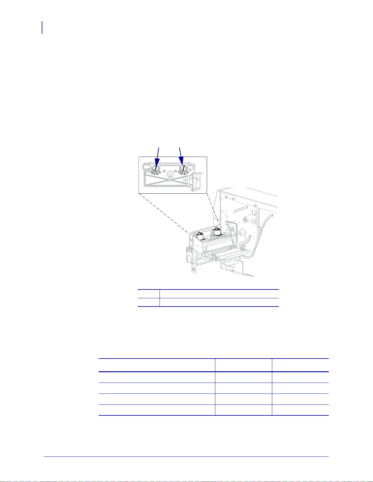
Operations
1
2
64
Adjust Printhead Pressure
Adjust Printhead Pressure
You may need to adjust printhead pressure if printing is too light on one side, if you use thick
media, or if the media drifts from side to side during printing.
See Figure 10. The ZM400 and RZ400 pres sure adjustment dials have four possible settings
designated by blocks of increasing size embossed on the print mechanism. The smallest block
(fully counterclockwise) is considered position 1, and the largest block (fully clockwise) is
considered position 4. The ZM600 and RZ600 dials have seven settings instead of four.
Figure 10 • Printhead Pressure Adjustment Dials
Outside dial
1
Inside dial
2
To set printhead pressure, complete these steps:
1. Use Table 9 or Table 10 to select the initial dial settings for your media, depending on
which printer you have.
Media Width
1 in. (25.4 mm)
2 in. (51 mm)
3 in. (76 mm)
3.5 in. and up (89 mm and up)
79695L-003 Z Series®/RZ™ Series User Guide 1/11/11
Table 9 • ZM400 and RZ400 Printhead Pressure
Inside Dial Outside Dial
31
41
32
33
Page 65

Adjust Printhead Pressure
Table 10 • ZM600 and RZ600 Printhead Pressure
Operations
65
Media Width
Inside Dial Outside Dial
2 in. (50 mm) 6 1
3 in. (75 mm) 6 2
4 in. (100 mm) 7 3
5 in. (125 mm) 7 4
5.5 in. and up (140 mm and up) 6 6
2. If necessary, adjust the pressure adjustment dials as follows:
If the media... Then...
Requires higher pressure to
Increase both dials one position.
print well
Shifts left while printing Increase the outside dial setting one position, or
decrease the inside dial setting one position.
Shifts right while printing Increase the inside dial setting one position, or
decrease the outside dial setting one position.
Prints too lightly on the left side
Increase the inside dial setting one position.
of the label.
Prints too lightly on the right
side of the label.
Increase the outside dial setting one position.
1/11/11 Z Series®/RZ™ Series User Guide 79695L-003
Page 66

Operations
Notes • ___________________________________________________________________
__________________________________________________________________________
__________________________________________________________________________
__________________________________________________________________________
__________________________________________________________________________
__________________________________________________________________________
__________________________________________________________________________
__________________________________________________________________________
__________________________________________________________________________
__________________________________________________________________________
66
Adjust Printhead Pressure
79695L-003 Z Series®/RZ™ Series User Guide 1/11/11
Page 67

4
Configuration
This section describes the control panel parameters that are used to configure the printer for
operation.
Contents
Setup Mode . . . . . . . . . . . . . . . . . . . . . . . . . . . . . . . . . . . . . . . . . . . . . . . . . . . . . . . . . . . 68
Enter and Use Setup Mode . . . . . . . . . . . . . . . . . . . . . . . . . . . . . . . . . . . . . . . . . . . . . 68
Exit Setup Mode. . . . . . . . . . . . . . . . . . . . . . . . . . . . . . . . . . . . . . . . . . . . . . . . . . . . . . 69
Change Password-Protected Parameters . . . . . . . . . . . . . . . . . . . . . . . . . . . . . . . . . . . . 70
Default Password Value. . . . . . . . . . . . . . . . . . . . . . . . . . . . . . . . . . . . . . . . . . . . . . . . 70
Disable the Password Protection Feature . . . . . . . . . . . . . . . . . . . . . . . . . . . . . . . . . . 70
Print a Configuration Label. . . . . . . . . . . . . . . . . . . . . . . . . . . . . . . . . . . . . . . . . . . . . . . . 71
Print a Network Configuration Label . . . . . . . . . . . . . . . . . . . . . . . . . . . . . . . . . . . . . . . . 72
Standard Control Panel Parameters . . . . . . . . . . . . . . . . . . . . . . . . . . . . . . . . . . . . . . . . 73
Additional Control Panel Parameters. . . . . . . . . . . . . . . . . . . . . . . . . . . . . . . . . . . . . . . . 98
1/11/11 Z Series®/RZ™ Series User Guide 79695L-003
Page 68

Configuration
68
Setup Mode
Setup Mode
After you have installed the media and ribbon and the Power- On Self T e st (POST) is complete,
the control panel displays
PRINTER READY. You may now set printer parameters for your
application using the control panel display and the buttons directly below it. If it becomes
necessary to restore the initial printer defaults, see FEED and PAUSE Self Test on page 135.
Important • Certain printing conditions may require that you adjust printing parameters,
such as print speed, darkness, or print mode. These conditions include (but are not
limited to):
• printing at high speeds
• peeling the media
• the use of extremely thin, small, synthetic, or coated labels
Because these and other factors affect print quality, run tests to determine the best
combination of printer settings and media for your applic ation. A poor mat ch may limit p rint
quality or print rate, or the printer may not fu nction properly in the desired print mode.
Note • If the printer is operating on an IP network and you have a ZebraNet wired or
wireless print server, you can change the printer’s parameters in these additional ways:
• with ZebraLink™ WebView. For information, see the appropriate print server user guide.
• with ZebraNet Bridge. For information, see the ZebraNet Bridge Enterprise Printer
Management User Guide.
Enter and Use Setup Mode
Use the LCD on the control panel to view and adjust printer settings through Setup mode.
When a parameter is changed, an asterisk (*) appears in the upper left corner of the display to
indicate that the value is different from the one currently active in the printer.
Press this key... To do the following...
SETUP/EXIT
SELECT
PLUS (+)
MINUS (-)
enter or exit Setup mode.
select or deselect a parameter.
continue to the next parameter.
return to the previous parameter in the cycle.
79695L-003 Z Series®/RZ™ Series User Guide 1/11/11
Page 69

Exit Setup Mode
When you exit setup mode, you have several options for saving, changing, or not changing
parameters.
To leave Setup mode, complete these steps:
1. While in Setup mode, press SETUP/EXIT.
The LCD displays
2. Press PLUS (+) or MINUS (-) to display the save options:
LCD Description
SAVE CHANGES.
Configuration
Setup Mode
69
PERMANENT
TEMPORARY
CANCEL
LOAD DEFAULTS
LOAD LAST SAVE
DEFAULT NET
3. Press SETUP/EXIT to select the displayed choice.
When the configuration and calibration sequence is done,
Stores values in the printer even when power is turned off.
Saves the changes until power is turned off.
Cancels all changes made since you entered Setup mode,
except for changes made to the darkness and tear-off settings,
which go into effect as soon as they are made.
Restores all parameters other than the network settings back to
the factory defaults. Use care when loading defaults because
you will need to reload all settings that you changed manually.
Note • On non-RFID printers, loading factory defaults
causes the printer to auto-calibrate.
Loads values from the last permanent save.
Restores the wired and wireless network settings back to
factory defaults.
PRINTER READY displays.
1/11/11 Z Series®/RZ™ Series User Guide 79695L-003
Page 70

Configuration
70
Change Password-Protected Parameters
Change Password-Protected Parameters
Certain parameters, including the communication parameters, are password-protected by
factory default.
Caution • Do not change password-protected parameters unless you have a complete
understanding of the parameters’ functions. If the parameters are set incorrectly, the printer
may function unpredictably.
The first time that you attempt to change a password-protected parameter, the printer displays
ENTER PASSWORD. Before you can change the parameter, you must enter the four-digit
numeric password. After you have entered the password correctly, you do not have to enter it
again unless you leave Setup mode by pressing
To enter a password for a password-protected parameter, complete
these steps:
1. At the password prompt, use MINUS (-) to change the selected digit position.
2. When you have selected the digit that you wish to change, use PLUS (+) to increase the
selected digit value. Repeat these two steps for each digit of the password.
SETUP/EXIT or by turning off (O) the printer.
3. After entering the password, press SELECT.
The parameter you selected to change is displayed. If the password was entered correct ly,
you can change the value.
Default Password Value
The default password value is 1234. The password can be changed using the Zebra
Programming Language (ZPL) command
pages (ZebraNet wired or wireless print server required).
^KP (Define Password) or using the printer’s web
Disable the Password Protection Feature
You can disable the password protection feature so that it no longer prompts you for a
password by setting the password to 0000 via the
password-protection feature, send the ZPL comma nd
1 to 9999.
^KP ZPL command. To re-enable the
^KPx, where x can be any number from
79695L-003 Z Series®/RZ™ Series User Guide 1/11/11
Page 71
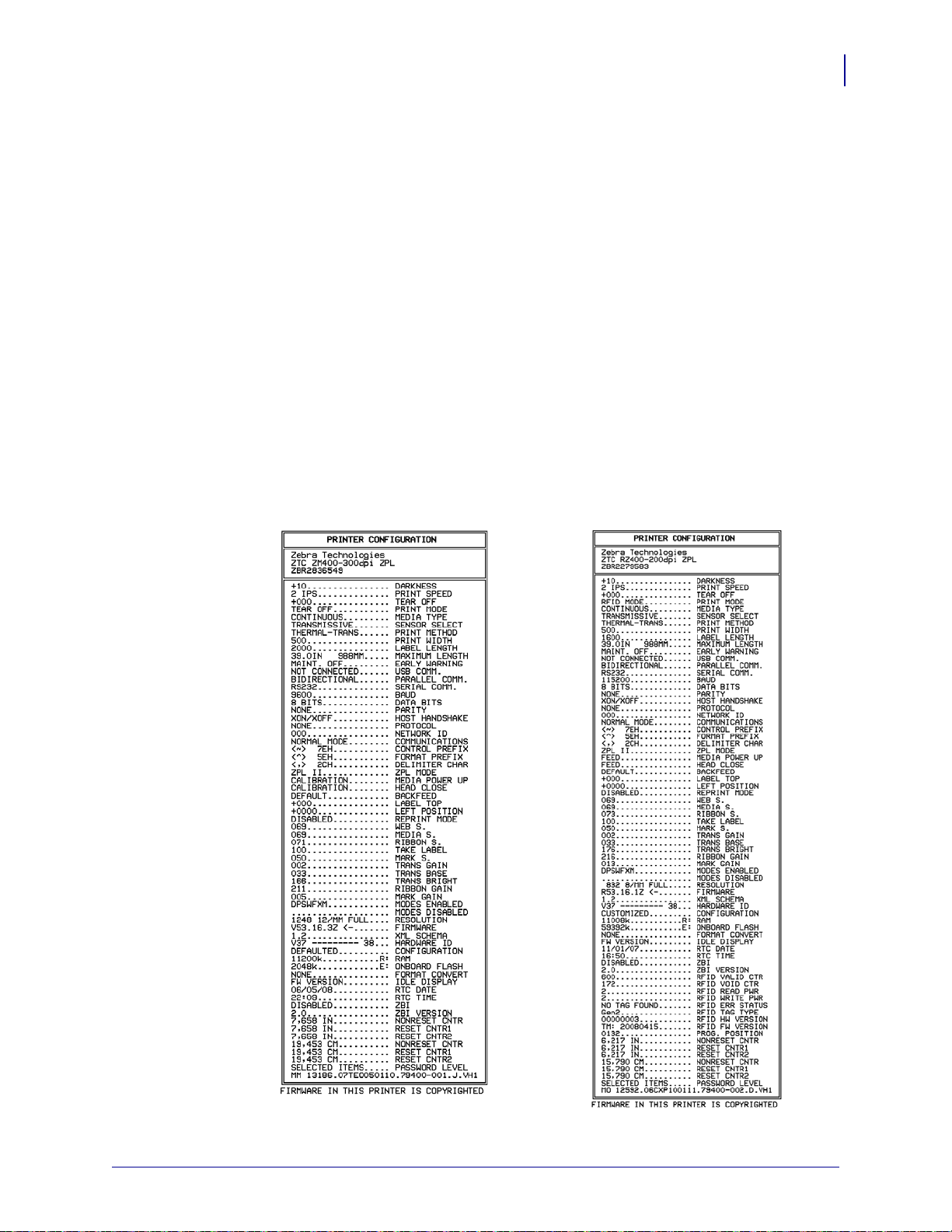
Print a Configuration Label
Z Series RZ Series
A configuration label lists the printer settings that are stored in configuration memory. After
you load the media, print a configuration label as a record of your printer’s current settings.
Keep the label to use when troubleshooting printing problems.
To print a configuration label, complete these steps:
1. On the control panel, press SETUP/EXIT.
2. Press PLUS (+) or MINUS (-) to scroll through the parameters until you reach
LIST SETUP.
3. Press SELECT to select the parameter.
4. Press PLUS (+) to confirm printing.
A configuration label prints (Figure 11).
Figure 11 • Sample Configuration Label
Configuration
Print a Configuration Label
71
1/11/11 Z Series®/RZ™ Series User Guide 79695L-003
Page 72
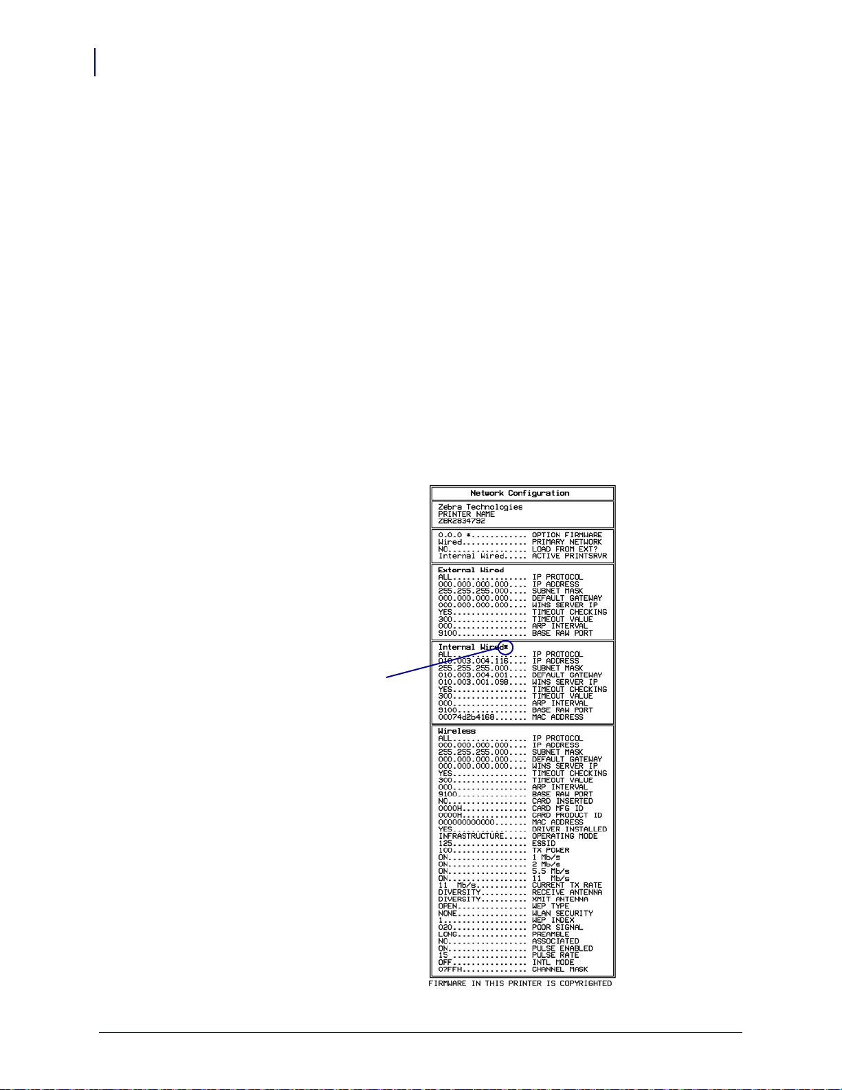
Configuration
asterisk
indicating the
active print
server
72
Print a Network Configuration Label
Print a Network Configuration Label
If you are using a print server, you can print a network configuration label after the printer is
connected to the network.
To print a network configuration label, complete these steps:
1. On the control panel, press SETUP/EXIT.
2. Press PLUS (+) or MINUS (-) to scroll through the parameters until you reach
LIST NETWORK.
3. Press SELECT to select the parameter.
4. Press PLUS (+) to confirm printing.
A network configuration label prints (Figure 12). An asterisk designates whether the
wired or wireless print server is active. If n o wi reless print server is installed, the wireless
portion of the label does no t print.
Figure 12 • Sample Network Configuration Label
(with a Wireless Print Server installed)
79695L-003 Z Series®/RZ™ Series User Guide 1/11/11
Page 73

Standard Control Panel Parameters
Table 11 shows parameters in the order in which they are displayed when you press PLUS (+)
after entering Setup mode. For parameters that do not appear in this table, see Additional
Control Panel Parameters on page 98.
Note • Your label preparation software or the printer driver may override adjustments made
through the control panel. Refer to the software or driver documentation for more
information.
Table 11 • Printer Parameters (Page 1 of 25)
Configuration
Standard Control Panel Parameters
73
Language/Parameter
Action/Explanation
Adjust Print Darkness
Darkness (burn duration) settings depend on a variety of factors, including
ribbon type, media type, and the conditi on of the printhead . You may adjust
the darkness for consistent high-quality printing.
Important • Set the darkness to the lowest setting that provides
good print quality. If the darkness is set too high, the ink may
smear, the ribbon may burn through, or the printhead may wear
prematurely.
If printing is too light or if there are voids in printed areas, increase the
darkness. If printing is too dark or if there is spreading or bleeding of
printed areas, decrease the darkness.
The FEED Self Test on page 132 can be used to determine the best darkness
setting. You may want to adjust darkness while performing the PAUSE Self
Test on page 131. Because the darkness setting takes effect immediately,
you can see the results on labels that are currently printing. Darkness
settings also may be changed by the driver or software settings.
Default Value (ZPL): +10
Range (ZPL): 00 to +30
Default Value (EPL): +7
Range (EPL): 00 to +15
To change the value shown:
1. Press SELECT to select the parameter.
2. Press PLUS (+) to increase darkness.
3. Press MINUS (-) to decrease darkness.
4. Press SELECT to accept any changes and deselect the parameter.
1/11/11 Z Series®/RZ™ Series User Guide 79695L-003
Page 74

Configuration
74
Standard Control Panel Parameters
Table 11 • Printer Parameters (Page 2 of 25)
Language/Parameter
Action/Explanation
Adjust Print Speed
Adjusts the speed for printing a label (given in inches per second). Slower
print speeds typically yield better print quality. Print speed changes take
effect upon exiting Setup mode.
Default Value (ZPL): 2 IPS
Default Value (EPL): 6 IPS
Range:
• 200 dpi: 2 to 10 IPS
• 300 dpi: 2 to 8 IPS
• 600 dpi: 1 to 4 IPS
To change the value shown:
1. Press SELECT to select the parameter.
2. Press PLUS (+) to increase the value.
3. Press MINUS (-) to decrease the value.
4. Press SELECT to accept any changes and deselect the parameter.
79695L-003 Z Series®/RZ™ Series User Guide 1/11/11
Page 75

Standard Control Panel Parameters
1
Media direction
2
Factory-set tear line location at position 00
1
2
Table 11 • Printer Parameters (Page 3 of 25)
Configuration
75
Language/Parameter
Action/Explanation
Adjust the Tear-Off Position
This parameter establishes the position of the media over the
tear-off/peel-off bar after printing.
See Figure 13. Higher numbers move the media out (the tear line moves
closer to the leading edge of the next label), and lower numbers move the
media in (the tear line moves closer to the edge of the label just printed).
Figure 13 • Tear-Off Position Adjustment
Default Value: 0
Range: -120 to +120
To change the value shown:
1. Press SELECT to select the parameter.
2. Press PLUS (+) to increase the value. Each press adjusts the tear-off
position by four dot rows.
3. Press MINUS (-) to decrease the value. Each press adjusts the tear-off
position by four dot rows.
4. Press SELECT to accept any changes and deselect the parameter.
1/11/11 Z Series®/RZ™ Series User Guide 79695L-003
Page 76

Configuration
76
Standard Control Panel Parameters
Table 11 • Printer Parameters (Page 4 of 25)
Language/Parameter
Action/Explanation
Select Print Mode
This parameter tells the printer how printed labels will be removed. Make
sure that you select a print mode that is compatible with your printer and
printer options. For information about how the print modes work with
different printer options, see Print Modes and Printer Options on page 40.
Default Value (non-RFID printers): TEAR-OFF
Selections (non-RFID printers): TEAR-OFF, PEEL-OFF, CUTTER,
DELAYED CUT, LINERLESS-P, LINERLESS-R, LINERLESS-T,
REWIND
Default Value (RFID printers): RFID MODE
Selections (RFID printers): TEAR-OFF, PEEL-OFF, CUTTER,
DELAYED CUT, LINERLESS-P, LINERLESS-R, RFID MODE,
LINERLESS-T, REWIND
Note • The linerless selections apply only to printers that have the
Linerless option.
To change the value shown:
1. Press SELECT to select the parameter.
2. Press PLUS (+) or MINUS (-) to scroll through the options.
3. Press SELECT to accept any changes and deselect the parameter.
Set Media Type
This parameter tells the printer the type of media that you are using (see
Types of Media on page 34 for more information). Selecting continuous
media requires that you include a label length instruction in your label
format (
^LLxxxx if you are using ZPL or ZPL II).
When non-continuous media is selected, the printer feeds media to
calculate label length (the distance between two recognized registration
points of the inter-label gap, webbing, or alignment notch or hole).
Default Value: GAP/NOTCH
Selections: GAP/NOTCH, MARK, CONTINUOUS
To change the value shown:
1. Press SELECT to select the parameter.
2. Press PLUS (+) or MINUS (-) to scroll through the options.
3. Press SELECT to accept any changes and deselect the parameter.
79695L-003 Z Series®/RZ™ Series User Guide 1/11/11
Page 77

Standard Control Panel Parameters
Table 12 • Print Width Ranges and Maximum Values
Printhead
Resolution
Printer
ZM400/RZ400 ZM600/RZ600
200 dpi
Default Value: 832
Range: 2 to 832 dots
Default Value: 1344
Range: 2 to 1344 dots
300 dpi
Default Value: 1248
Range: 2 to 1248 dots
Default Value: 1984
Range: 2 to 1984 dots
600 dpi
Note • 600 dpi is
not available on the
RZ400.
Default Value: 2496
Range: 2 to 2496 dots
N/A
Table 11 • Printer Parameters (Page 5 of 25)
Configuration
77
Language/Parameter
Action/Explanation
Select Print Method
The print method parameter tells the printer the me thod of printin g that you
want to use: direct thermal (no ribbon) or thermal transfer (using thermal
transfer media and ribbon).
Default Value: THERMAL TRANSFER
Selections: THERMAL TRANSFER, DIRECT THERMAL
To change the value shown:
1. Press SELECT to select the parameter.
2. Press PLUS (+) or MINUS (-) to scroll through the options.
3. Press SELECT to accept any changes and deselect the parameter.
Set Print Width
This parameter specifies the printable area across the width of the label.
Table 12 shows the ranges and default values for print width , which are
based on the printer model and the printhead resolution.
To change the value shown:
1. Press SELECT to select the parameter.
2. Press PLUS (+) or MINUS (-) to change the value shown.
3. Press SELECT to accept any changes and deselect the parameter.
1/11/11 Z Series®/RZ™ Series User Guide 79695L-003
Note • Setting the width too narrow can result in portions of a label
format not being printed on the media. Setting the width too wide
wastes formatting memory and can cause printing off of the label
and on the platen roller. This setting can affect the horizontal
position of the label format if the image was inverted using the
^POI ZPL II command.
Page 78

Configuration
}
2
1
Label length (including interlabel gap)
2
Interlabel gap
3
Set maximum label length to approximately this value
1
3
78
Standard Control Panel Parameters
Table 11 • Printer Parameters (Page 6 of 25)
Language/Parameter
Action/Explanation
Set Maximum Label Length
This parameter is used during the media portion of the calibration process.
Always set maximum label length to a value that is at least 1.0 in.
(25.4 mm) greater than the actual label length (Figure 14). If the value is set
to a smaller value than the label length, the printer assumes that continuous
media is loaded, and the printer cannot calibrate.
For example, if the label length is 5.0 inches (126 mm) including the
interlabel gap, set the parameter for 6.0 inches (152 mm). If the label length
is 7.5 inches (190 mm), set the parameter for 9.0 inches (229 mm).
Figure 14 • Label Length
Default Value: 39.0 inches (988 mm)
Selections: Values are adjustable in one-inch (25.4 mm) increments
To change the value shown:
1. Press SELECT to select the parameter.
2. Press PLUS (+) or MINUS (-) to change the value shown.
79695L-003 Z Series®/RZ™ Series User Guide 1/11/11
3. Press SELECT to accept any changes and deselect the parameter.
Page 79

Standard Control Panel Parameters
Table 11 • Printer Parameters (Page 7 of 25)
Configuration
79
Language/Parameter
Action/Explanation
Set Early Warning for Maintenance
When this feature is enabled, the printer provides warnings when the
printhead needs to be cleaned.
Default Value: MAINT. OFF
Selections: MAINT. OFF, MAINTENANCE ON
To change the Early Warning settings:
1. Press SELECT to select the parameter.
2. When the LCD displays EARLY WARNING MAINTENANCE, press
PLUS (+) or MINUS (-) to toggle between OFF and ON. (If you are
prompted for a password, enter your password usin g the instructions in
Change Password-Protected Parameters on page 70.)
3. Exit Setu p mode and save changes to enable additional parameters
related to the early warning system.
4. Enter Setup mode again and go to the following parameters to enter the
printhead cleaning interval and the printhead life.
5. Press SELECT to accept any changes and deselect the parameter.
Set Printhead Cleaning Interval for Early Warning
This parameter appears only when Early Warning for Maintenance is
enabled. This value should correspond to the length of the media or ribbon
roll that you are using.
Default Value: 450 M/1476 FT
Selections: 100 M/328 FT to 450 M/1476 FT in 50 M increments
To change the value shown:
1. Press SELECT to select the parameter.
2. Press PLUS (+) or MINUS (-) to set the printhead clea ning interval to the
desired number of inches of media or ribbon.
When the printhead reaches the set length,
PRINTHEAD
appears on the LCD. If the alert function is enabled, the
WARNING CLEAN
printer generates an alert.
1. Press SELECT to accept any changes and deselect the parameter.
Reset Printhead Cleaning Counter for Early Warning
This parameter appears only when Early Warning for Maintenance is
enabled.
To reset the printhead cleaning counter:
1. Press SELECT to select the parameter.
2. Did you clean the printhead?
• If you cleaned the printhead, press PLUS (+) to select YES.
• If you did not clean the printhead, press MINUS (-) to select NO.
3. Press SELECT to accept any changes and deselect the parameter.
1/11/11 Z Series®/RZ™ Series User Guide 79695L-003
Page 80

Configuration
80
Standard Control Panel Parameters
Table 11 • Printer Parameters (Page 8 of 25)
Language/Parameter
Action/Explanation
Set Printhead Life for Early Warning
This parameter appears only when Early Warning for Maintenance is
enabled. Set this value to the number of inches of media that the printhead
is expected to print.
Default Value: 1,000,000 inches
Range: 100 to 1,000,000 inches
To change the value shown:
1. Press SELECT to select the parameter.
2. Press MINUS (-) to move the cursor.
3. Press PLUS (+) to increase the value of the digit.
When the printhead reaches the set length,
HEAD
appears on the LCD. If the alert function is enabled, the printer
WARNING REPLACE
generates an alert.
1. Press SELECT to accept any changes and deselect the parameter.
Reset Printhead Life Counter for Early Warning
This parameter appears only when Early Warning for Maintenance is
enabled.
To reset the printhead life counter:
1. Press SELECT to select the parameter.
2. Did you replace the printhead?
• If you replaced the printhead, press PLUS (+) to select YES.
• If you did not replace the printhead, press MINUS (-) to select NO.
3. Press SELECT to accept any changes and deselect the parameter.
View Non-Resettable Counter
This parameter displays the total length of media that the printer has
printed. You can use ZPL commands to change the unit of measure for this
counter. For the commands, refer to the Programming Guide for ZPL, ZBI,
Set-Get-Do, Mirror, and WML.
View User-Controlled Counter 1
This parameter displays the total length of media that the printer has printed
since this parameter was last reset. You can use ZPL commands to change
the unit of measure and reset this counter. For the commands, refer to the
Programming Guide for ZPL, ZBI, Set-Get-Do, Mirror, and WML.
View User-Controlled Counter 2
This parameter displays the total length of media that the printer has printed
since this parameter was last reset. You can use ZPL commands to change
the unit of measure and reset this counter. For the commands, refer to the
Programming Guide for ZPL, ZBI, Set-Get-Do, Mirror, and WML.
79695L-003 Z Series®/RZ™ Series User Guide 1/11/11
Page 81
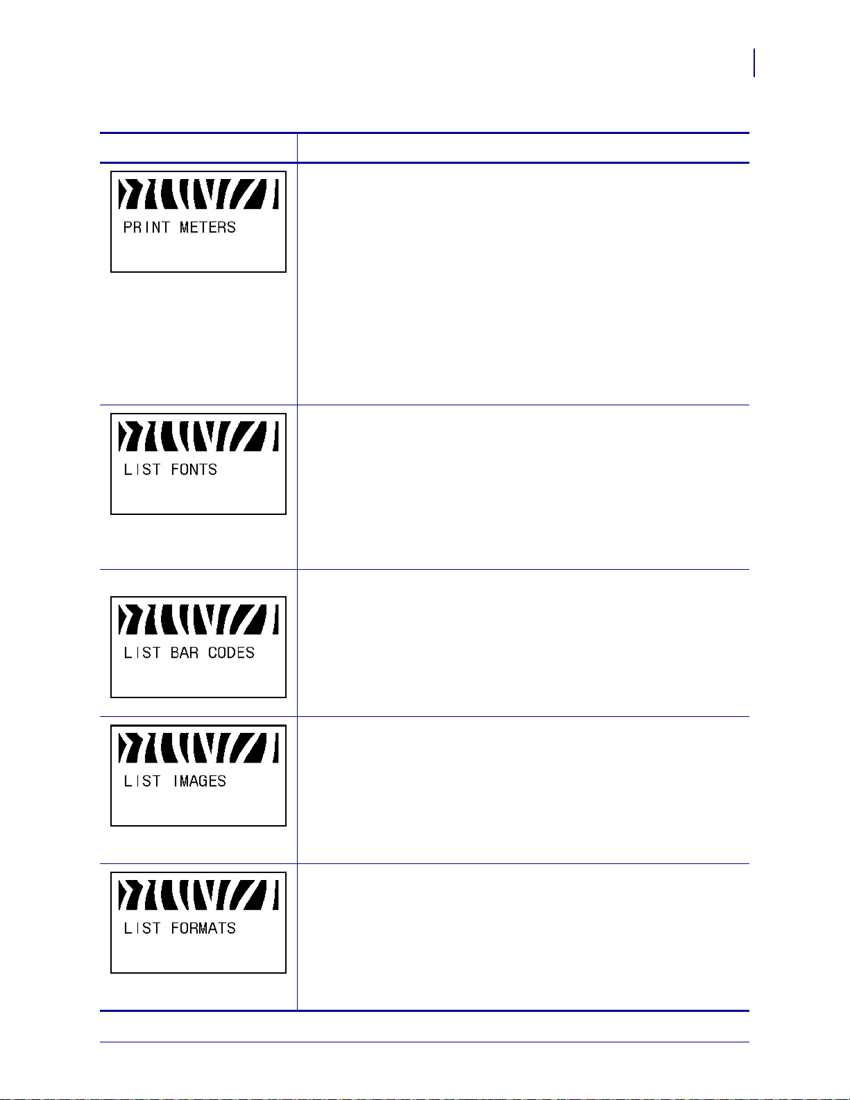
Standard Control Panel Parameters
Table 11 • Printer Parameters (Page 9 of 25)
Configuration
81
Language/Parameter
Action/Explanation
Print Counter Readings
Prints a label that lists the odometer readings for the following:
• the non-resettable counter
• the two user-controlled counters
• the Early Warning for Maintenance counters, which indicate when the
printhead was last cleaned and the printhead life
If the Early Warning for Maintenance feature is disabled, the counters
related to it do not print.
To print a list of the odometer readings:
1. Press SELECT to select the parameter.
2. Press PLUS (+) to print the odometer readings.
3. Press SELECT to deselect the parameter.
List Fonts
This option prints a label that lists the available fonts in the printer,
including standard printer fonts plus any optional font s. Fonts may be
stored in RAM or Flash memory.
To print a list of the available fonts:
1. Press SELECT to select the parameter.
2. Press PLUS (+) to select PRINT.
3. Press SELECT to deselect the parameter.
ZPL only List Bar Codes
This option prints a label that lists the available bar codes in t he printer. Bar
codes may be stored in RAM or Flash memory.
To print a list of the available bar codes:
1. Press SELECT to select the parameter.
2. Press PLUS (+) to select PRINT.
3. Press SELECT to deselect the parameter.
List Images
This option prints a label that lists the available images stored in the
printer’ s RA M, Fl ash memory, or optional memory card.
To print a list of the available images:
1. Press SELECT to select the parameter.
2. Press PLUS (+) to select PRINT.
3. Press SELECT to deselect the parameter.
List Formats
This option prints a label that lists the available formats stored in the
printer’ s RA M, Fl ash memory, or optional memory card.
To print a list of the available formats:
1. Press SELECT to select the parameter.
2. Press PLUS (+) to select PRINT.
3. Press SELECT to deselect the parameter.
1/11/11 Z Series®/RZ™ Series User Guide 79695L-003
Page 82

Configuration
82
Standard Control Panel Parameters
Table 11 • Printer Parameters (Page 10 of 25)
Language/Parameter
Action/Explanation
List Setup
This option prints a configuration label (see Figure 11 on page 71), which
lists the current printer configuration.
To print a configuration label:
1. Press SELECT to select the parameter.
2. Press PLUS (+) to select PRINT.
3. Press SELECT to deselect the parameter.
List Network Settings
This option prints a network configuration label (see Figure 12
on page 72), which lists the settings for any print server that is installed.
To print a network configuration label:
1. Press SELECT to select the parameter.
2. Press PLUS (+) to select PRINT.
3. Press SELECT to deselect the parameter.
List All
This option prints labels that list the available fonts, bar codes, images,
formats, and the current printer and network configurations.
To print labels for all settings:
1. Press SELECT to select the parameter.
2. Press PLUS (+) to select PRINT.
3. Press SELECT to deselect the parameter.
79695L-003 Z Series®/RZ™ Series User Guide 1/11/11
Page 83
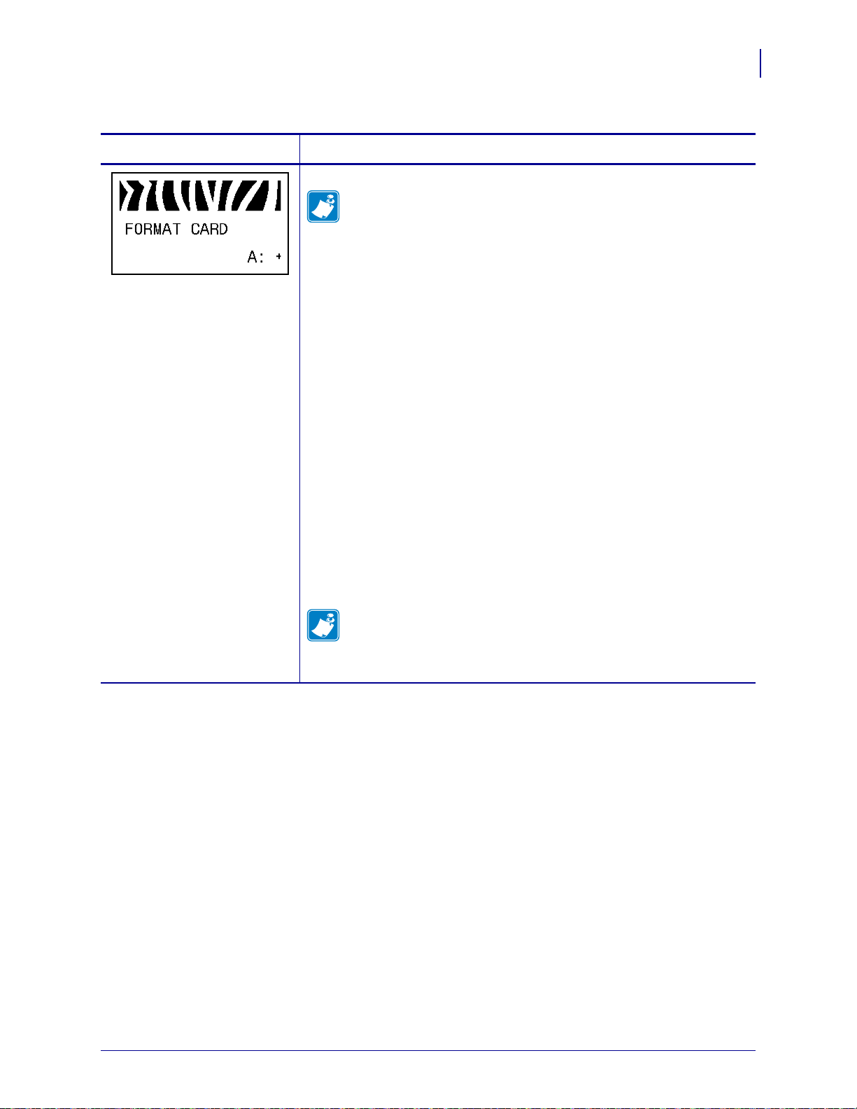
Standard Control Panel Parameters
Table 11 • Printer Parameters (Page 11 of 25)
Configuration
83
Language/Parameter
Action/Explanation
Format Memory Card
Note • This parameter appears only when a Wireless Plus option
board with the flash chip populated is installed.
This option erases all previously stored information from the 64 MB flash
chip.
Caution • This option completely erases the flash chip.
To format a memory card:
1. Press SELECT to select the parameter.
2. Press PLUS (+) to select A: or OPT:MEM (APL-D only).
If your printer is set to require a password, you are prompted to enter
the password.
3. Enter the password. For instructions, see Change Password-Protected
Parameters on page 70.
4. Press the appropriate button again to select the desired card.
The display shows
5. Do you want to continue?
• Press MINUS (-) to select NO to cancel the request and return to
ARE YOU SURE?.
FORMAT CARD prompt.
• Press PLUS (+) to select YES and begin initialization.
When initialization is complete, the control panel displays
FORMATTING CARD COMPLETED.
Note • Depending on the amount of memory in the memory card,
initialization may take up to 5 minutes to complete.
6. Press SELECT to deselect the parameter.
1/11/11 Z Series®/RZ™ Series User Guide 79695L-003
Page 84

Configuration
84
Standard Control Panel Parameters
Table 11 • Printer Parameters (Page 12 of 25)
Language/Parameter
Action/Explanation
Initialize Flash Memory
This option erases all previously stored information from Flash memory.
Caution • This option completely erases the Flash memory.
To initialize Flash memory:
1. Press SELECT to select the parameter.
2. If prompted for a password, enter the printer password. For instructions,
see Change Password-Protected Parameters on page 70.
The display shows
3. Press PLUS (+) to select YES.
The display shows
4. Do you want to continue?
• Press MINUS (-) to select NO to cancel the request and return to the
INITIALIZE FLASH?
ARE YOU SURE?.
INITIALIZE FLASH prompt.
• Press PLUS (+) to select YES and begin initialization.
When initialization is complete, the control panel displays
INITIALIZING MEMORY COMPLETED.
Note • Depending on the amount of free FLASH memory,
initialization may take up to 1 minute to complete.
5. Press SELECT to accept any changes and deselect the parameter.
Print Sensor Profile
A sensor profile shows sensor settings compared to actual sensor readings.
This label (which will extend across several actual labels or tags) can be
used to troubleshoot printing problems. To interpret the results of the
sensor profile, see Sensor Pro fil e on page 137.
To print a sensor profile:
1. Press SELECT to select the parameter.
2. Press PLUS (+) to start this standard calibration procedure and print a
media sensor profile.
3. If the sensitivity of the sensors must be adjusted, perform Calibrate
Media and Ribbon Sensor Sensitivity on page 85.
4. Press SELECT to accept any changes and deselect the parameter.
79695L-003 Z Series®/RZ™ Series User Guide 1/11/11
Page 85

Standard Control Panel Parameters
1
2
Table 11 • Printer Parameters (Page 13 of 25)
Configuration
85
Language/Parameter
Action/Explanation
Calibrate Media and Ribbon Sensor Sensitivity
Use this procedure to adjust sensitivity of media and ribbon sensors.
Important • Follow this procedure exactly as presented. All of the
steps must be performed even if only one of the sensors requires
adjustment. You may press
MINUS (-) at any step in this procedure
to cancel the process.
To perform a media and ribbon sensor calibration:
1. Press SELECT to select the parameter.
2. Press PLUS (+) to start the calibration procedure.
LOAD BACKING prompt displays.
The
1. Open the printhead.
2. Remove approximately 8 in. (203 mm) of labels from the backing
(liner), and pull the media into the printer so that only the back ing is
between the media sensors.
3. If your printer has the Peel-Off, Liner Take-Up, or Rewind option,
complete the following substeps:
a. Push down the peel-off mechanism release lever to open the peel
assembly.
b. Feed the liner over the tear-of f/peel-of f bar (1) and behind the peel
assembly (
2). Make sure that the end of the liner falls outside of
the printer.
1/11/11 Z Series®/RZ™ Series User Guide 79695L-003
Page 86
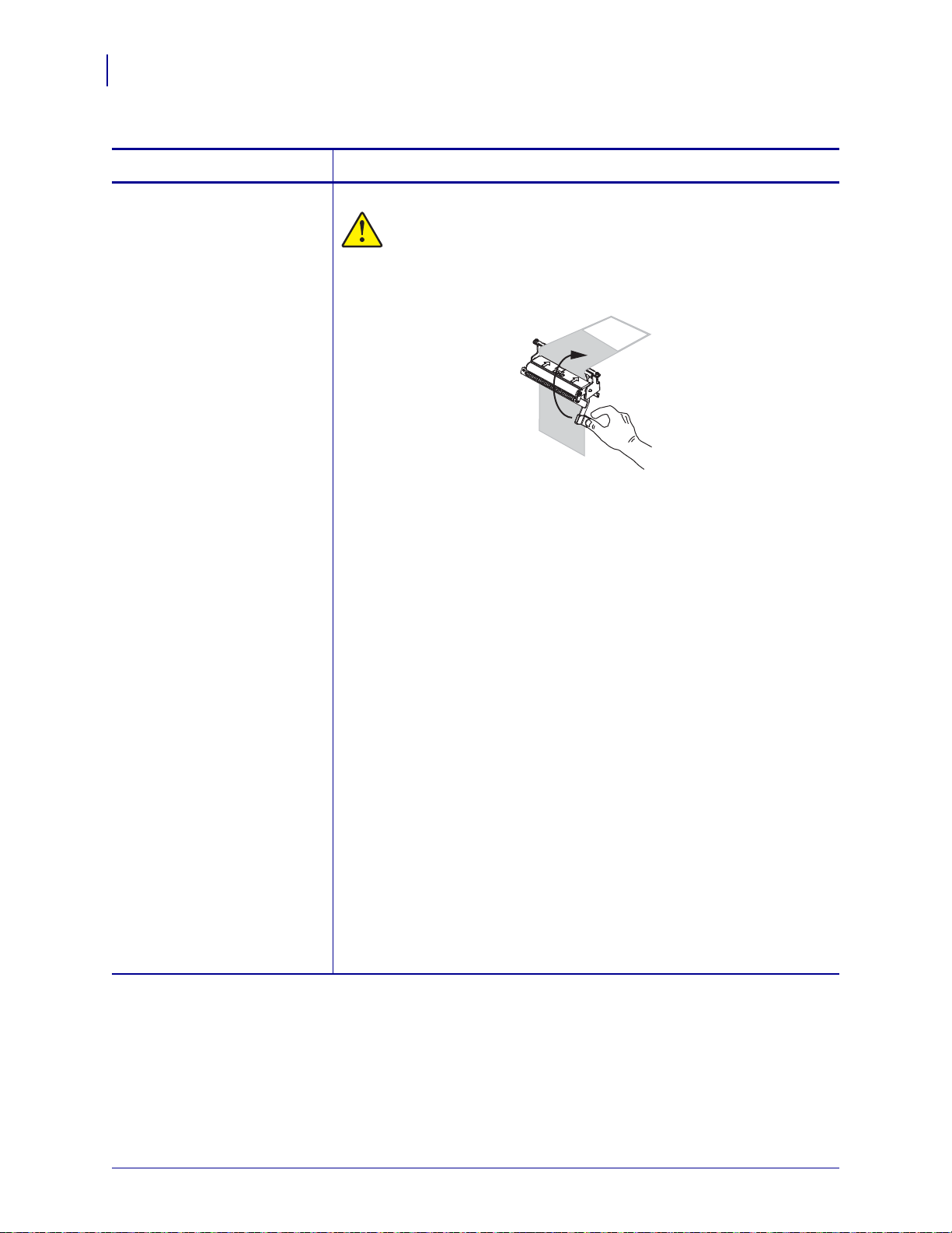
Configuration
86
Standard Control Panel Parameters
Table 11 • Printer Parameters (Page 14 of 25)
Language/Parameter
(continued from previous
page)
Action/Explanation
Calibrate Media and Ribbon Sensor Sensitivity (continued)
Caution • Use the peel release lever and your right hand to close
the peel assembly. Do not use your left hand to assist in closing.
The top edge of the peel roller/assembly could pinch your fingers.
c. Close the peel assembly using the peel-off mechanism release
lever.
4. Leave the printhead open.
5. Press PLUS (+) to continue.
REMOVE RIBBON prompt displays.
The
1. Remove the ribbon (if used).
2. Close the printhead.
3. Press PLUS (+) to continue.
The message
CALIBRATING PLEASE WAIT displays.
The printer adjusts the scale (gain) of the signals that it receives from
the media and ribbon sensors based on the specific media and ribbon
combination being used. On the sensor profile, this essentially
corresponds to moving the peak of the graph up or down to optimize the
readings for your application.
When calibration is complete, RELOAD ALL displays.
1. Open the printhead and pull the media forward until a label is
positioned under the media sensor.
2. Reload the ribbon (if used).
3. Close the printhead.
4. Press PLUS (+) to continue.
The printer performs an auto-calibration. During this process, the
printer checks the readings for the media and ribbon based on the new
scale established, determines the label length, and determines the print
mode. To see the new readings on the new scale, print a sensor profile.
1. Press SELECT to accept any changes and deselect the parameter.
79695L-003 Z Series®/RZ™ Series User Guide 1/11/11
Page 87

Standard Control Panel Parameters
Table 11 • Printer Parameters (Page 15 of 25)
Configuration
87
Language/Parameter
Action/Explanation
Set Parallel Communications
Select the communications port that ma tches the one bein g used by the host
computer.
Default Value: BIDIRECTIONAL
Selections: BIDIRECTIONAL, UNIDIRECTIONAL
To change the value shown:
1. Press SELECT to select the parameter.
2. Press PLUS (+) or MINUS (-) to scroll through the options.
3. Press SELECT to accept any changes and deselect the parameter.
ZPL only Set Serial Communications
Select the communications port that ma tches the one bein g used by the host
computer. This setting applies only when the serial port is used.
Note • Select RS232 if you are using an external adapter to enable
RS422/485 operation.
Default Value: RS232
Selections: RS232, RS485 MULTIDROP
To change the value shown:
1. Press SELECT to select the parameter.
2. Press PLUS (+) or MINUS (-) to scroll through the options.
3. Press SELECT to accept any changes and deselect the parameter.
Set Baud
This setting applies only when the serial port is used. The baud setting of
the printer must match the baud setting of the host computer for accurate
communications to take place. Select the value that matches the one being
used by the host computer.
Default Value: 9600
Selections (ZPL, APL-I, APL-D): 300, 600, 1200, 2400, 4800, 9600, 14400,
19200, 28800, 38400, 57600, 115200
Selections (EPL): 1200, 2400, 4800, 9600, 19200, 38400, 57600, 115200
To change the value shown:
1. Press SELECT to select the parameter.
2. Press PLUS (+) or MINUS (-) to scroll through the options.
3. Press SELECT to accept any changes and deselect the parameter.
1/11/11 Z Series®/RZ™ Series User Guide 79695L-003
Page 88

Configuration
88
Standard Control Panel Parameters
Table 11 • Printer Parameters (Page 16 of 25)
Language/Parameter
Action/Explanation
Set Data Bits
This setting applies only when the serial port is used. The data bits of the
printer must match the data bits of the host computer for accurate
communications to take place. Set the data bits to match the setting being
used by the host computer.
Default Value: 8BITS
Selections: 7BITS, 8BITS
To change the value shown:
1. Press SELECT to select the parameter.
2. Press PLUS (+) or MINUS (-) to toggle between the options.
3. Press SELECT to accept any changes and deselect the parameter.
Set Parity
This setting applies only when the serial port is used. The parity of the
printer must match the parity of the host computer for accurate
communications to take place. Select the parity that matches the one being
used by the host computer.
Default Value: NONE
Selections: EVEN, ODD, NONE
To change the value shown:
1. Press SELECT to select the parameter.
2. Press PLUS (+) or MINUS (-) to scroll through the options.
3. Press SELECT to accept any changes and deselect the parameter.
Set Host Handshake
This setting applies only when the serial port is used. The handshake
protocol of the printer must match the handshake protocol of the host
computer for communication to take place. Select the handshake protocol
that matches the one being used by the host computer.
Default Value (ZPL): XON/XOFF
Selections (ZPL): XON/XOFF, DSR/DTR, RTS/CTS
Default Value (EPL): DTR & XON/XOFF
Selections (EPL): DTR & XON/XOFF, DTR
To change the value shown:
1. Press SELECT to select the parameter.
2. Press PLUS (+) or MINUS (-) to scroll through the options.
3. Press SELECT to accept any changes and deselect the parameter.
79695L-003 Z Series®/RZ™ Series User Guide 1/11/11
Page 89
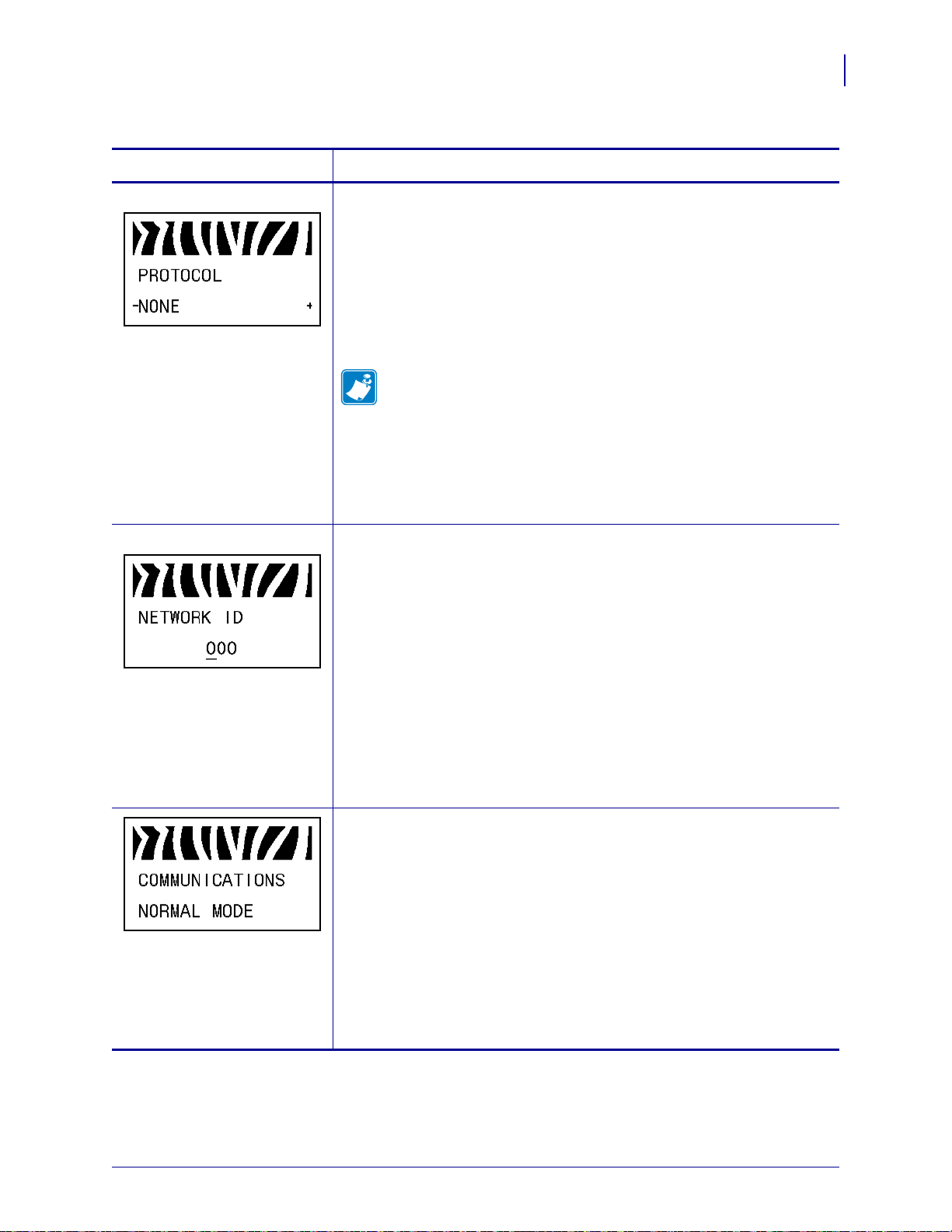
Standard Control Panel Parameters
Table 11 • Printer Parameters (Page 17 of 25)
Configuration
89
Language/Parameter
Action/Explanation
ZPL only Set Protocol
Protocol is a type of error checking system. Depending on the selection, an
indicator may be sent from the printer to the host computer signifying that
data has been received. Select the protocol that is requested by the host
computer. Further details on protocol can be found in the Programming
Guide for ZPL, ZBI, Set-Get-Do, Mirror, and WML.
Default Value: NONE
Selections: NONE, ZEBRA, ACK_NAK
Note • ZEBRA is the same as ACK_NAK, except that ZEBRA
response messages are sequenced. If
must use
To change the value shown:
1. Press SELECT to select the parameter.
2. Press PLUS (+) or MINUS (-) to scroll through the options.
3. Press SELECT to accept any changes and deselect the parameter.
ZPL only Set Network ID
This parameter assigns a unique number to the printer when the printer is
operating in an RS422/485 multi-drop network environment (an external
RS422/485 adapter is required). This gives the host computer the mean s to
address a specific printer. This does not affect TCP/IP or IPX networks.
ZEBRA is selected, the printer
DSR/DTR for host handshake protocol.
Default Value: 000
Range: 000 to 999
To change the value shown:
1. Press SELECT to select the parameter.
2. Press MINUS (-) to move to the next digit position.
3. Press PLUS (+) to increase the value of the digit.
4. Press SELECT to accept any changes and deselect the parameter.
Set Communications Mode
The communication diagnostics mode is a troubleshooting tool for
checking the interconnection between the printer and the host computer.
For more information, see Communications Diagnostics Test on page 136.
Default Value: NORMAL MODE
Selections: NORMAL MODE, DIAGNOSTICS
To select communication diagnostics mode:
1. Press SELECT to select the parameter.
2. Press PLUS (+) or MINUS (-) to toggle between the options.
3. Press SELECT to accept any changes and deselect the parameter.
1/11/11 Z Series®/RZ™ Series User Guide 79695L-003
Page 90

Configuration
90
Standard Control Panel Parameters
Table 11 • Printer Parameters (Page 18 of 25)
Language/Parameter
Action/Explanation
ZPL only Set Control Prefix Character
The printer looks for this two-digit hex character to indicate the start of a
ZPL/ZPL II control instruction.
Note • Do not use the same hex value for the control, format, and
delimiter character. The printer must see different characters to
work properly.
Default Value: 7E ~
Range: 00 to FF
To change the value shown:
1. Press SELECT to select the parameter.
2. Press MINUS (-) to move to the next digit position.
3. Press PLUS (+) to increase the value of the digit.
4. Press SELECT to accept any changes and deselect the parameter.
ZPL only Set Format Prefix Character
The format prefix is a two-digit hex value used a s a parameter plac e marker
in ZPL/ZPL II format instructions. The printer looks for this hex character
to indicate the start of a ZPL/ZPL II format instruction. See the
Programming Guide f or ZPL, ZBI, Se t-Get-Do, M irror , and WML for more
information.
Note • Do not use the same hex value for the control, format, and
delimiter character. The printer must see different characters to
work properly.
Default Value: 5E ^
Range: 00 to FF
To change the value shown:
1. Press SELECT to select the parameter.
2. Press MINUS (-) to move to the next digit position.
3. Press PLUS (+) to increase the value of the digit.
4. Press SELECT to accept any changes and deselect the parameter.
79695L-003 Z Series®/RZ™ Series User Guide 1/11/11
Page 91

Standard Control Panel Parameters
Table 11 • Printer Parameters (Page 19 of 25)
Configuration
91
Language/Parameter
Action/Explanation
ZPL only Set Delimiter Character
The delimiter character is a two-digit hex value used as a parameter place
marker in ZPL/ZPL II format instructions. See the Pr ogramming Guide for
ZPL, ZBI, Set-Get-Do, Mirror, and WML for more information.
Note • Do not use the same hex value for the control, format, and
delimiter character. The printer must see different characters to
work properly.
Default Value: 2C ,
Range: 00 to FF
To change the value shown:
1. Press SELECT to select the parameter.
2. Press MINUS (-) to move to the next digit position.
3. Press PLUS (+) to increase the value of the digit.
4. Press SELECT to accept any changes and deselect the parameter.
ZPL only Select ZPL Mode
The printer remains in the selected mode until it is changed by this
parameter or by using a ZPL/ZPL II command. The printer accepts label
formats written in either ZPL or ZPL II, eliminating th e need to rewrit e any
ZPL formats that already exist. See the Programming Guide for ZPL, ZBI,
Set-Get-Do, Mirror, and WML for more information on the differences
between ZPL and ZPL II.
Default Value: ZPL II
Range: ZPL II, ZPL
To change the value shown:
1. Press SELECT to select the parameter.
2. Press PLUS (+) or MINUS (-) to toggle between the options.
3. Press SELECT to accept any changes and deselect the parameter.
1/11/11 Z Series®/RZ™ Series User Guide 79695L-003
Page 92

Configuration
92
Standard Control Panel Parameters
Table 11 • Printer Parameters (Page 20 of 25)
Language/Parameter
Action/Explanation
Select Media Power-Up Option
This parameter sets the action of the media when you turn on the printer.
Default Value (non-RFID printers): CALIBRATION
Default Value (RFID printers): FEED
Selections: CALIBRATION, SHORT CAL, LENGTH, NO MOTION,
FEED
• Calibration adjusts sensor levels and thresholds, determines length,
and feeds the media to the next web.
• Short Cal sets media and web thresholds without adjusting sensor
gain, determines length, and feeds the media to the next web.
• Length determines lab el len gt h usin g curren t senso r value s, and
feeds the media to the next web.
• No Motion tells the printer not to move the media. You must
manually ensure that the web is po sitioned correctly, or press feed to
position the next web.
• Feed—feeds the lab els to th e first regist ration point.
To change the value shown:
1. Press SELECT to select the parameter.
2. Press PLUS (+) or MINUS (-) to scroll through the options.
3. Press SELECT to accept any changes and deselect the parameter.
Select Head Close Option
This parameter sets the action of the media when you close the printhead.
Default Value (non-RFID printers): CALIBRATION
Default Value (RFID printers): FEED
Selections: CALIBRATION, SHORT CAL, LENGTH, NO MOTION,
FEED
• Calibration adjusts sensor levels and thresholds, determines length,
and feeds the media to the next web.
• Short Cal sets media and web thresholds without adjusting sensor
gain, determines length, and feeds the media to the next web.
• Length determines lab el len gt h usin g curren t senso r value s, and
feeds the media to the next web.
• No Motion tells the printer not to move the media. You must
manually ensure that the web is po sitioned correctly, or press feed to
position the next web.
• Feed—feeds the lab els to th e first regist ration point.
To change the value shown:
1. Press SELECT to select the parameter.
2. Press PLUS (+) or MINUS (-) to scroll through the options.
3. Press SELECT to accept any changes and deselect the parameter.
79695L-003 Z Series®/RZ™ Series User Guide 1/11/11
Page 93

Standard Control Panel Parameters
Table 11 • Printer Parameters (Page 21 of 25)
Configuration
93
Language/Parameter
Action/Explanation
Select Backfeed Sequence
This parameter sets when label backfeed occurs after a label is removed in
some print modes. It has no effect in Rewind mode. This setting is
superseded by
~JS when received as part of a label format (see the
Programming Guide f or ZPL, ZBI, Se t-Get-Do, M irror , and WML for more
information).
Default Value: DEFAULT (90%)
Selections: DEFAULT, AFTER, OFF, BEFORE, 10%, 20%, 30%, 40%,
50%, 60%, 70%, 80%
To change the value shown:
1. Press SELECT to select the parameter.
2. Press PLUS (+) or MINUS (-) to scroll through the options.
3. Press SELECT to accept any changes and deselect the parameter.
Adjust Label Top Position
This parameter adjusts the print position vertically on the label. Positive
numbers adjust the label top position farther down the label (away from the
printhead) by the specified number of dots. Negative numbers adjust the
position up the label (toward the printhead).
Default Value: +000
Range: -120 to +120
To change the value shown:
1. Press SELECT to select the parameter.
2. Press PLUS (+) to increase the value.
3. Press MINUS (-) to decrease the value.
4. Press SELECT to accept any changes and deselect the parameter.
Adjust Left Position
This parameter adjusts the print position horizontally on the label. Positive
numbers adjust printing to the left by the specified number of dots.
Negative numbers shift printing to the right.
Default Value: 0000
Range: –9999 to +9999 dots
To change the value shown:
1. Press SELECT to select the parameter.
2. Press MINUS (-) to move the cursor.
3. Press PLUS (+) to change between +/- and to increase the value of the
digit. For a negative value, ent er the value be fore changi ng to the minus
sign.
4. Press SELECT to accept any changes and deselect the parameter.
1/11/11 Z Series®/RZ™ Series User Guide 79695L-003
Page 94
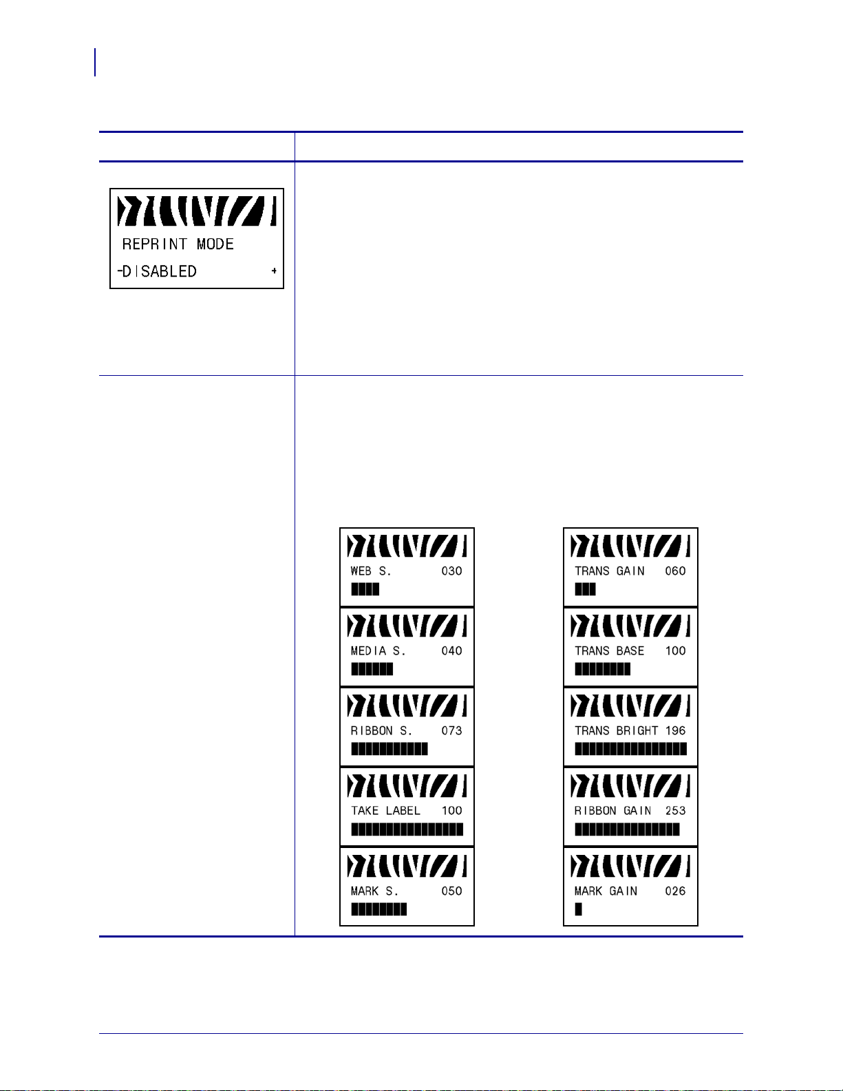
Configuration
94
Standard Control Panel Parameters
Table 11 • Printer Parameters (Page 22 of 25)
Language/Parameter
Action/Explanation
ZPL only Set Reprint Mode
When reprint mode is enabled, you can reprint the last label printed either
by issuing the ~PR ZPL command or by pressing MINUS (-) on the control
panel.
Default Value: DISABLED
Selections: ENABLED, DISABLED
To change the value shown:
1. Press SELECT to select the parameter.
2. Press PLUS (+) or MINUS (-) to toggle between the options.
3. Press SELECT to accept any changes and deselect the parameter.
See next column View Sensor Settings
These parameters are automatically set during the calibration procedure
and should be changed only by a qualified service technician. Refer to the
Programming Guide for ZPL, ZBI, Set-Get-Do, Mirror, and WML for
information on these parameters.
To skip these parameters:
1. Press PLUS (+) to skip each of the following parameters:
79695L-003 Z Series®/RZ™ Series User Guide 1/11/11
Page 95

Standard Control Panel Parameters
Table 11 • Printer Parameters (Page 23 of 25)
Configuration
95
Language/Parameter
Action/Explanation
ZPL only Select Format Convert
Selects the bitmap scaling factor. The first number is the original dots per
inch (dpi) value; the second, the dpi to which you would like to scale.
Default Value: NONE
Selections: NONE, 150 300, 150 600, 200 600, 300 600
To change the value shown:
1. Press SELECT to select the parameter.
2. Press PLUS (+) or MINUS (-) to scroll through the options.
3. Press SELECT to accept any changes and deselect the parameter.
Select Idle Display
This parameter selects the LCD options for the real-time clock.
Note • If the default value is not selected, pressing PLUS (+) or
MINUS (-) briefly displays the firmware version of the printer.
Default Value: FIRMWARE (FW) VERSION
Selections: MM/DD/YY (24HR), MM/DD/YY (12HR), DD/MM/YY
(24HR), DD/MM/YY (12HR), FW VERSION
To change the value shown:
1. Press SELECT to select the parameter.
2. Press PLUS (+) or MINUS (-) to scroll through the options.
3. Press SELECT to accept any changes and deselect the parameter.
1/11/11 Z Series®/RZ™ Series User Guide 79695L-003
Page 96

Configuration
96
Standard Control Panel Parameters
Table 11 • Printer Parameters (Page 24 of 25)
Language/Parameter
Action/Explanation
Set Real-Time Clock (RTC) Date
This parameter allows you to set the date following the convention selected
in IDLE DISPLAY.
To change the value shown:
1. Press SELECT to select the parameter.
2. Press MINUS (-) to move to the next digit position.
3. Press PLUS (+) to change the value of the digit.
4. Press SELECT to accept any changes and deselect the parameter.
Set RTC Time
This parameter allows you to set the time following the convention sel ected
IDLE DISPLAY.
in
To change the value shown:
1. Press SELECT to select the parameter.
2. Press the left oval MINUS (-) to move to the next digit position.
3. Press the right oval PLUS (+) to change the value of the digit.
4. Press SELECT to accept any changes and deselect the parameter.
Specify Password Level
This parameter allows you to select whether certain factory-selected menu
items or all menu items are password protected.
Default Value: SELECTED ITEMS
Selections: SELECTED ITEMS, ALL ITEMS
1. Press SELECT to select the parameter.
2. Press PLUS (+) or MINUS (-) to toggle between the options.
3. Press SELECT to accept any changes and deselect the parameter.
79695L-003 Z Series®/RZ™ Series User Guide 1/11/11
Page 97

Standard Control Panel Parameters
Table 11 • Printer Parameters (Page 25 of 25)
Configuration
97
Language/Parameter
Action/Explanation
Select the Display Language
This parameter changes the language displayed on the LCD . Each language
selection is displayed in the language itself.
Default Value: ENGLISH
Selections: ENGLISH, SPANISH, FRENCH, GERMAN, ITALIAN,
NORWEGIAN, PORTUGUESE, SWEDISH, DANISH, SPANISH 2,
DUTCH, FINNISH, JAPANESE, KOREAN, SIMPLIFIED CHINESE,
TRADITIONAL CHINESE
To change the value shown:
1. Press SELECT to select the parameter.
2. Press PLUS (+) or MINUS (-) to scroll through the options.
3. Press SELECT to accept any changes and deselect the parameter.
1/11/11 Z Series®/RZ™ Series User Guide 79695L-003
Page 98

Configuration
98
Additional Control Panel Parameters
Additional Control Panel Parameters
Additional parameters appear in the following situations.
• When a Radio Frequency Identification (RFID) reader is installed. For more information,
refer to the RFID Programming Guide.
• When a wired print server is installed in the printer. For more information, refer to the
ZebraNet 10/100 Print Server User and Reference Guide
• When a wireless print server is installed in the printer. Refer to the ZebraNet Wireless
User Guide.
Copies of the print server manuals and the RFID Programming Guide are available at
http://www.zebra.com/manuals or on the user CD that came with your printer.
79695L-003 Z Series®/RZ™ Series User Guide 1/11/11
Page 99

Routine Maintenance
This section provides routine cleaning and maintenance procedures.
5
Contents
Replacing Printer Components . . . . . . . . . . . . . . . . . . . . . . . . . . . . . . . . . . . . . . . . . . . 100
Ordering Replacement Parts . . . . . . . . . . . . . . . . . . . . . . . . . . . . . . . . . . . . . . . . . . . 100
Recycling Printer Components . . . . . . . . . . . . . . . . . . . . . . . . . . . . . . . . . . . . . . . . . 100
Lubrication . . . . . . . . . . . . . . . . . . . . . . . . . . . . . . . . . . . . . . . . . . . . . . . . . . . . . . . . . . . 100
Cleaning Schedule and Procedures. . . . . . . . . . . . . . . . . . . . . . . . . . . . . . . . . . . . . . . . 101
Clean the Exterior . . . . . . . . . . . . . . . . . . . . . . . . . . . . . . . . . . . . . . . . . . . . . . . . . . . 101
Clean the Printhead and Platen Roller. . . . . . . . . . . . . . . . . . . . . . . . . . . . . . . . . . . . 102
Clean the Media Compartment and Sensors. . . . . . . . . . . . . . . . . . . . . . . . . . . . . . . 105
Clean the Cutter Module . . . . . . . . . . . . . . . . . . . . . . . . . . . . . . . . . . . . . . . . . . . . . . 106
Routine Maintenance for the Rewind Option . . . . . . . . . . . . . . . . . . . . . . . . . . . . . . . . . 108
Remove Printed Labels or Liner from the Rewind Spindle . . . . . . . . . . . . . . . . . . . . 108
Adjust Media Alignment for Rewind Option . . . . . . . . . . . . . . . . . . . . . . . . . . . . . . . . 110
1/11/11 Z Series®/RZ™ Series User Guide 79695L-003
Page 100
100
Routine Maintenance
Replacing Printer Components
Replacing Printer Components
Ordering Replacement Parts
For optimal printing quality and proper printer performance across our product line, Zebra
strongly recommends the use of genuine Zebra™ supplies as part of the total solution.
Specifically, the ZM400, ZM600, RZ400, and RZ600 are designed to work only with genuine
Zebra™ printheads, thus maximizing safety and print quality.
Contact your authorized Zebra reseller for part ordering information, or see Contacts
on page 11 for contact addresses and telephone numbers.
Recycling Printer Components
The majority of this printer’s components are recyclable. The printer’s main logic board
includes a battery that you should dispose of properly.
Do not dispose of any printer components in unsorted municipal waste. Please dispose of the
battery according to your local regulations, and recycle the other printer components
according to your local standards. For more information, see
http://www.zebra.com/environment.
Lubrication
No lubrication is needed for this printer.
Caution • Some commercially available lubricants will damage the finish and the
mechanical parts if used on this printer.
79695L-003 Z Series®/RZ™ Series User Guide 1/11/11
 Loading...