

Zebra Zebra MotionWorks Enterprise Platform Software MotionWorks Enterprise Configuration Guide v2.0
Page 1

MotionWorks
Enterprise
2.0
Configuration Guide
P1123393-03EN
Page 2

ZEBRA and the stylized Zebra head are trademarks of Zebra Technologies Corporation, registered in
many jurisdictions worldwide. All other trademarks are the property of their respective owners.
© 2022 Zebra Technologies Corporation and/or its affiliates. All rights reserved.
Information in this document is subject to change without notice. The software described in this document
is furnished under a license agreement or nondisclosure agreement. The software may be used or copied
only in accordance with the terms of those agreements.
For further information regarding legal and proprietary statements, please go to:
SOFTWARE:zebra.com/linkoslegal
COPYRIGHTS:zebra.com/copyright
WARRANTY:zebra.com/warranty
END USER LICENSE AGREEMENT: zebra.com/eula
Terms of Use
Proprietary Statement
This manual contains proprietary information of Zebra Technologies Corporation and its subsidiaries
(“Zebra Technologies”). It is intended solely for the information and use of parties operating and
maintaining the equipment described herein. Such proprietary information may not be used, reproduced,
or disclosed to any other parties for any other purpose without the express, written permission of Zebra
Technologies.
Product Improvements
Continuous improvement of products is a policy of Zebra Technologies. All specifications and designs are
subject to change without notice.
Liability Disclaimer
Zebra Technologies takes steps to ensure that its published Engineering specifications and manuals are
correct; however, errors do occur. Zebra Technologies reserves the right to correct any such errors and
disclaims liability resulting therefrom.
Limitation of Liability
In no event shall Zebra Technologies or anyone else involved in the creation, production, or delivery of the
accompanying product (including hardware and software) be liable for any damages whatsoever
(including, without limitation, consequential damages including loss of business profits, business
interruption, or loss of business information) arising out of the use of, the results of use of, or inability to
use such product, even if Zebra Technologies has been advised of the possibility of such damages. Some
jurisdictions do not allow the exclusion or limitation of incidental or consequential damages, so the above
limitation or exclusion may not apply to you.
Publication Date
July 2021
2
Page 3

Contents
MWE Configuration Guide ................................................................................................................. 4
Launching the Web Client............................................................................................... 6
Changing the Administrator Password............................................................................. 7
Adding site groups, sites, and site maps.......................................................................... 8
Adding Site Groups .................................................................................................. 8
Adding Sites ........................................................................................................... 10
Adding Maps........................................................................................................... 12
Calibrating a Map ................................................................................................... 16
Registering a Zebra Location Appliance (ZLA) .............................................................. 19
Associating a ZLA with a site ......................................................................................... 21
System Builder............................................................................................................... 23
Launching System Builder...................................................................................... 23
Adding Infrastructure Devices ................................................................................ 27
Specifying Location Algorithms .............................................................................. 46
Device Manager............................................................................................................. 47
Defining Zones............................................................................................................... 48
Configuring Authentication Modes ................................................................................. 49
Database ................................................................................................................ 49
LDAP ...................................................................................................................... 50
ADFS ...................................................................................................................... 52
Database, ADFS..................................................................................................... 53
Installing a SSL Certificate............................................................................................ 54
Camel Interface and REST API ..................................................................................... 55
Configuring Email Notifications ...................................................................................... 56
Resource Alerts ...................................................................................................... 56
Device Alerts .......................................................................................................... 57
ZLA Median and Rate Filters ......................................................................................... 58
Other Configuration Tasks ............................................................................................. 61
Reference Documents ................................................................................................... 62
Appendix: BLE Receiver Configuration ......................................................................................... 63
3
Page 4

MWE Configuration Guide
This document provides instructions for configuring the MotionWorks Enterprise (MWE) 2.0.n software
from Zebra Technologies Corporation after it has been installed. The ‘n’ in the version number indicates
the latest 2.0 release. For installation instructions and server requirements, please see the separate
document MWE 2.0 Installation Guide.
When configuring MWE, it is helpful to understand its basic architecture and the relations between its
software modules. The simplified diagram below illustrates the main MWE software components hosted by
the MWE server and some of the external clients and consumers.
4
Page 5

MWE Configuration Guide
An MWE deployment may or may not require a ZLA, which is a CentOS appliance that captures data from
different types of sensors, puts the data in a standard format, and forwards it to the MWE server. For
example, MWE 2.0 supports deployment of passive RFID readers without a ZLA, sending data directly to
the MWE server. Also, you could have a location sensor or third-party application feeding data to MWE via
the MWE API. However, most type of sensors supported by MWE 2.0 do require a ZLA.
Please note that the screenshots and figures included in this document may vary slightly from the MWE
2.0.n version that you have installed, where n identifies different version or releases of the MWE 2.0
release.
5
Page 6

Launching the Web Client
Once MWE has been installed, most configuration tasks can be done using the MWE web client, along
with the System Builder discussed later in this document. To launch the client, open a web browser
(Chrome, Firefox, Edge, ….) on a client machine or server on the network, and point it to
http://MWE_Server_Name, where MWE_Server_Name is the MWE Linux server name or IP address. The
login page will be displayed:
MWE Configuration Guide
Default login credentials are Username =
See Changing the Administrator Password on page 7 for information regarding how to change the default
password.
Observe the landing page and the main menu bar at the top of the page. The menu items are: Dashboard,
Reports, History, Alerts, Infrastructure, Configuration, Users, admin (the name of the account currently
logged in).
The default admin / admin account has access to all items in the main menu bar.
The following sections describe a sequence of typical steps in configuring the MWE software.
admin and Password = admin.
6
Page 7

MWE Configuration Guide
Changing the Administrator Password
MWE includes a default administrator account with access to all menu items, pages and functionality
available in the web client:
• Username:
• Password:admin
To change the admin password, login using the admin account and select Change Password from the
admin tab:
admin
Enter the current password and the new password, and click Save.
Sign out by selecting admin > Sign Out from the main menu bar.
7
Page 8

MWE Configuration Guide
Adding site groups, sites, and site maps
One of the core functionalities of MWE is processing and displaying asset location data from multiple sites
across a city, country, or the world. This section explains how to add sites, site groups, and site maps to
the system.
Adding Site Groups
Open the Infrastructure > Site Manager page:
If you are using the default installation world map (refer to the MWE 2.0 Installation Guide) observe a world
map with few country names in the Site Manager window. The map in the figure above corresponds to a
more detailed map (north-america_us.mbtiles) installed at installation time.
8
Page 9

MWE Configuration Guide
For example, if your company has two sites in the city of Los Angeles, namely, a North LA site and a South
LA site, and you would like to group them under a group named Los Angeles. To add a site group, click the
+ Group link:
Enter the Site Group Name (Los Angeles) and click Save. The Site Manager tree-view pane will now
show the newly added site group name (Los Angeles):
Create additional site groups as needed.
9
Page 10

To edit or delete a site group, hover over the site group name or next to it. Two icons become visible; a
pencil icon and a trash can icon. Click the pencil icon to edit the site group name and click the trash can
icon to delete the site group.
Adding Sites
Add the North LA Site and South LA Site sites under the Los Angeles group, and click the + Site link to
add a site.
MWE Configuration Guide
Fill in the following fields:
Site Name Type in the desired site name
Location You can zoom and pan the map and then drag the blue pin to the correct address. Or
you can simply type the address and press the Enter key; the map will pan and zoom
and the pin will be placed in the correct location automatically.
Site Group Click the down arrow and select the desired site group, in this case Los Angeles.
10
Page 11

MWE Configuration Guide
NOTE: You will see a detailed street map, as show in the figure above, only if you have installed a detailed
map such as north-america_us.mbtiles at installation time. You will see no map in the above window if you
are working with the MWE default world map. Other than seeing no map in the above window, using the
default installation map does not affect MWE functionality.
Click the Save button and observe the North LA Site listed under the Los Angeles group:
Similarly, for the South LA Site:
11
Page 12

MWE Configuration Guide
To edit or delete a site, hover over the site name or next to it. Two icons become visible, namely, a pencil
icon and a trash can icon. Click the pencil icon to edit the site, and click the trash can icon to delete the
site.
The third icon, a set of parallel horizontal lines, allows a site to be dragged to a different Site Group.
Adding Maps
One or multiple maps can be added under each site. Assets whose location is being tracked will be shown
on these maps. If you have a multistory building at a site, you may want to add a map per floor. If you have
a campus with several buildings and parking lots and you would like to add a map for each of them.
12
Page 13

MWE Configuration Guide
To add a map under a site, hover over the site name or next to it, and observe the Edit icon (pencil icon)
next to it. Click the Edit icon. In the example below, we click on the Edit icon next to the North LA Site:
Click the + Upload link:
Provide the following information:
Name: Enter any map name you deem appropriate
File: Click the Select Site Map button and browse to the location on your local computer
where the map file you want to upload resides. In MWE 2.0, only windows
metafiles (.wmf) are supported.
Max Zoom Level: This defines how many times you will be able to zoom in when displaying the map
in the web client. The default value is 4 and the maximum available value is 8. For
large files, a lower zoom level will result in a smaller upload time.
13
Page 14

MWE Configuration Guide
Once you have selected a map file (.wmf), the map file name will be displayed:
Click the Upload button. The upload process may take from a few seconds to many minutes, depending
on the map size and Max Zoom Level selected. The reason is that the map is both being uploaded and
tiled for later use. Tiling is done only once when uploading a map into the system. Once the upload and
tiling process is completed, you will be returned to the site properties window.
The uploaded map name will be listed under Site Maps, and the map image will be displayed in the lower
section of the window, as shown in the figure below:
You can add more maps. After adding a second map named Parking Lot, you will see:
The Edit (pencil) and Delete (trash can) next to each map entry in the figure above and allow you to edit
or delete a map file.
14
Page 15

MWE Configuration Guide
Once you are done adding maps for this site, click the Save button. The tree-view pane will now show the
maps added under the North LA Site:
Clicking on a map entry displays the map image in the map window:
NOTE: In the figure above the label displayed on the lower right corner of the map window. It reads Map
coordinate system is not configured. We have uploaded a map image, but we have not calibrated the map,
that is, we have not defined an x,y coordinate system for each map in order to correctly display asset
locations on the map image.
15
Page 16

Calibrating a Map
To calibrate a map, click the gear icon on the map window toolbar:
Enter the known (x,y) coordinates for two points on opposite corners of the map. The example uses the
coordinates of the lower left and upper right corners of the square surrounding the map image, known from
a site survey.
MWE Configuration Guide
Click the Next Step button indicated by the red arrow in the figure above. You will see two yellow dots
labeled Lower Left and Upper Right which you can drag to the correct position on the map:
For better accuracy, zoom in when positioning the yellow dots. You can zoom in and out using your mouse
wheel or the + and – buttons on the map toolbar.
16
Page 17

MWE Configuration Guide
Finally, click the Save button:
The map is now calibrated. As you move your mouse over the map, observe the (x,y) coordinates
displayed on the lower right corner of the map window:
17
Page 18

MWE Configuration Guide
Registering a Zebra Location Appliance (ZLA)
A ZLA (Zebra Location Appliance) is an appliance that collects location and telemetry data from a variety
of sensor types and location devices, runs location algorithms and filters data, and forwards data across a
network to a MWE (Linux) server. A ZLA can be a physical device as in the picture below, or a virtual
machine.
Zebra Location Appliance (ZLA)
A deployment of MWE may or may not require a ZLA. For example, MWE 2.0 supports deployment of fixed
passive RFID readers without using a ZLA. Also, you could have a location sensor or third-party
application feeding data to MWE via the MWE API. However, most type of sensors supported by MWE 2.0
do require a ZLA.
A ZLA needs to be registered with a MWE server for the ZLA to be able to forward data to that server, and
for the MWE web client to be able to monitor, configure, and update the ZLA. If a ZLA was registered as
part of the MWE software installation process (see the MWE 2.0 Installation Guide) then the ZLA will
already be listed in the Infrastructure Appliances page:
The Status column will show Failed or Activating until a site.json configuration files is published to the
ZLA using System Builder. See System Builder on page 22.
NOTE: The ZLA firmware version must be 2.0.0-1 or higher. See the MWE 2.0 Installation Guide for details
on upgrading the ZLA firmware.
If the ZLA for a site has not yet been registered, here are the steps to register it (see the MWE 2.0
Installation Guide for more details):
1. Log into the ZLA using the root account (obtain login credentials from Zebra) and open a Terminal
window. You can use Putty or similar SSH client to remotely access the ZLA.
2. Change directory to /opt/zebra/zla/icsagent and run the configure script:
# cd /opt/zebra/zla/icsagent
18
Page 19

MWE Configuration Guide
# ./configure.sh
You will be prompted to enter some information and answer some yes/no questions. Answer as shown
in the figure below. For Server Host, enter the fully qualified domain server name or IP address of
your MWE Linux server.
3. Run the register script:
# ./register.sh
You will be prompted to enter some information and answer some yes/no questions. When prompted,
enter Username / Password (default is admin / admin) and enter a name of your choosing for the ZLA.
This name will be displayed in the MWE web client.
4. Restart the icsagent daemon:
# systemctl restart icsagent
At this point, the ZLA should be listed in the Infrastructure > Appliances page of a web client
pointing to the MWE server.
19
Page 20

MWE Configuration Guide
Associating a ZLA with a site
Once a ZLA has been registered with a MWE server, a web client pointing to that server will show the ZLA
listed in the Infrastructure > Appliances report:
NOTE: The Status column will show Activating or Failed until a site configuration file is uploaded to
the ZLA using the System Builder tool as explained in System Builder on page 22.
NOTE: The ZLA firmware version must be 2.0-1 or higher. Refer to the MWE 2.0 Installation Guide for
details on upgrading the ZLA firmware.
The next step is to associate the ZLA with a site by specifying the site where the ZLA is located, so that
tags and assets located by that ZLA will be reported by MWE in the correct site and on the correct map.
For example, if the ZLA in the figure above, named vzla20, is physically located at our North LA Site,
receiving and processing tag blinks from sensors at that site, we need to associate this ZLA with the North
LA Site. To do so, select the ZLA (check the checkbox in the first column), click the More link on the report
menu bar, and select Edit Appliance from the popup menu:
20
Page 21

MWE Configuration Guide
Click the down arrow in the Site field and select the correct site (North LA Site in our example) from the
drop-down list. Click Save. The Appliances page will now show under the Site column the site associated
with the ZLA:
A ZLA can be associated with only one logical site defined in the Site Manager page (see Adding site
groups, sites, and site maps on page 8). In practice, you can have several physical sites associated with a
single ZLA by adding multiple maps (one or more maps per physical site) under a logical site in the
Site Manager page.
21
Page 22

System Builder
The System Builder tool is used to define the configuration file consumed by a ZLA (Zebra Location
Appliance). If your MWE deployment does not require a ZLA, then you do not need to use System Builder.
If your deployment does require a ZLA, then the next step in the system configuration is to use System
Builder to perform the following tasks:
• On the map, add and place the location sensors and other infrastructure devices that are or will be
installed at the site.
• Specify the location algorithms to be used at the site. This is necessary only for some types of sensors.
This section describes the basic steps in System Builder required to perform the above tasks. For more
detailed information on System Builder functionality, refer to the System Builder User Guide.
Launching System Builder
The System Builder tool is installed by the MWE Tools installation program and can be run on the MWE
Windows Application Server or on any laptop.
1. To launch the tool, click the Zebra icon on the Windows taskbar. The tool launcher opens.
MWE Configuration Guide
2. Select the Installation tab and click the System Builder link:
Alternatively, use the Windows search tool to search for and launch System Builder.
22
Page 23

MWE Configuration Guide
When prompted, select MWE mode (as opposed to VSS legacy mode):
3.
4. Click the Download tool button (down arrow icon) to download maps from the MWE server. You will be
prompted to connect to the MWE server.
5. Enter the server name or IP address of the MWE (Linux) server. The admin login account is the same
as for the web client.
6. Click Connect.
You will be prompted to select a site from a list of all the sites you have previously added in the web
client. In this case, this list includes North LA Site and South LA Site. For this example, select North LA
Site. Click OK, and observe the Site Attributes dialog window.
7. At the top center of the dialog window, verify that the WhereNet option is selected in the Hardware
Support pane.
23
Page 24

MWE Configuration Guide
Accept all default settings and click OK:
8.
The System Builder displays one of the maps (Office Area map) belonging to the North LA Site (see
Adding site groups, sites, and site maps on page 8).
24
Page 25

MWE Configuration Guide
To switch to the second map (Parking Lot map) belonging to the North LA Site (see Adding site groups,
9.
sites, and site maps on page 8), click the Switch Map tool button.
Observe the list of all maps previously added under the North LA Site. Select the desired map to view:
After making any changes, publish to the MWE server or you can save locally to publish later.
10. To publish your changes, click the Publish tool button:
You will be prompted with a couple of confirmation windows.
11. Accept the default options and click Upload/OK when prompted.
When publishing in System Builder, the configuration information entered for the site is uploaded not only
to the MWE server, but also to the ZLA associated with the site. The location algorithms that run on the
ZLA need this information.
If you prefer to save your work to a local folder and publish later, select File > Save As... from the main
menu. System Builder will save all information in a text file, usually referred to as the site file, and it will also
automatically save to the same folder all map files (.wmf) associated with the site. The information in the
site file is in json format. You can later load the site file into System Builder by selecting File > Open
Site File… from the main menu.
25
Page 26

MWE Configuration Guide
Adding Infrastructure Devices
Devices that are installed as part of the location infrastructure may include different types of sensors or
devices supported by MWE, such as 24730 sensors, UWB sensors, passive RFID sensors, DART hubs,
BLE beacons, BLE bridges or mobile receivers, Zebra CLAS servers, Zebra Gemini, tag magnetic exciters,
time reference tags, and more. This section provides examples of how these devices are entered into the
system.
Entering the ZLA IP address
Before we add any devices, we need to enter in System Builder the IP address of the ZLA. As mentioned
in the previous section, when doing a Publish operation in System Builder, the system design information
entered into System Builder (such as location devices and location algorithms) is uploaded not only to the
MWE server but also to the ZLA associated with the site. This information is uploaded to the ZLA in the
form of a json file, named
site.json and commonly referred to as the site file.
This site
run the location algorithms. The Blink Service will check that the ZLA IP address in the site.json file
matches the actual IP address of the ZLA; if they don’t match, the Blink Service will not run.
1. To enter the ZLA IP address into System Builder, double-click the ZLP Host item in the tree-view pane:
.json file is read by the ZLS Service and the Blink Service on the ZLA; these are the services that
26
Page 27
MWE Configuration Guide
Type in the correct ZLA IP address in the IP Address field and click OK:
2.
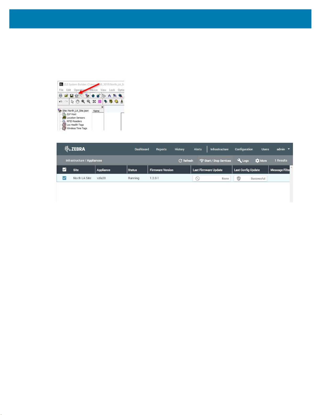
3. If you click the Publish tool button (up arrow) on the top toolbar, the map calibration and ZLA IP
address is uploaded to the MWE server and to the ZLA, and the Infrastructure > Appliances page
in the web client should show Status = Running, and Last Config Update = Successful for the
ZLA:
Adding BLE Beacons
This section describes how to add BLE beacons. In one typical deployment scenario, BLE beacons are
placed at fixed locations throughout a facility. When a WhereNet tag with a built-in BLE scanner comes
close to a BLE beacon, the tag will read the beacon’s MAC address and other parameters, and include this
information in the tag blink (tag RFID transmission). A WhereLAN sensor hearing the tag blink will forward
the digitized information to a ZLA across the network. The Blink Service on the ZLA will read the MAC
address from the tag blink and assign to that tag the x,y coordinates of the BLE beacon having that MAC
address in the site.json configuration file published by System Builder. Finally, the Blink Service will
forward the tag ID, and x,y coordinates to the MWE server. This is essentially a presence location
algorithm.
Fixed BLE beacons can also be used to perform full locate (Presence, 2-D, 3-D) of BLE receivers, which
are devices that scan for Bluetooth smart beacon emissions and forward the data via a WiFi access point
to a (http) server or ZLA on the network. The receiver will forward the MAC addresses and RSSI signal
intensity of the fixed beacons it detected, and the Blink Service on the ZLA will then calculate the location
of the receiver using the known locations and RSSI values of the fixed beacons.
27
Page 28

MWE Configuration Guide
To add a BLE beacon in System Builder:
1. Right-click on the spot on the map where you want to place the BLE beacon, and select New > New
BLE Beacon from the popup menu:
A BLE beacon icon is shown on the map where you right-clicked, and BLE1 is shown in the lists of BLE
beacons in the middle pane:
2. Drag the BLE icon on the map to the desired location.
3. Double-click on the BLE icon on the map or on BLE1 in the middle pane. The BLE Properties window
will open:
28
Page 29
MWE Configuration Guide
In the Category drop-down list, select Beacon.
4.
5. In the Model drop-down list, select your beacon model.
6. In the Beacon MAC/ID field, type in the Beacon MAC address.
The x,y values shown are the ones of the spot where you placed the BLE beacon on the map. If you
have more accurate x,y values (from a survey, etc), you can type them in the above window, and click
OK.
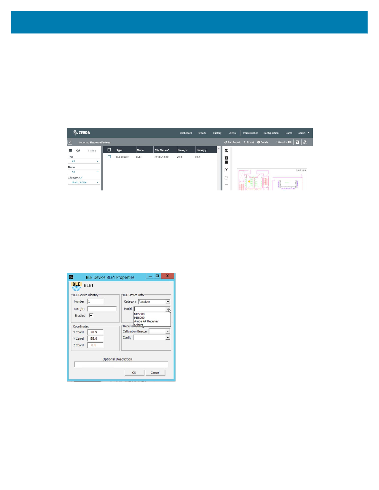
Add as many additional BLE beacons on each map as necessary. When you publish, all devices that
you have added will be shown in the Config > Hardware Devices page in the web client:
Adding BLE Receivers
A BLE receiver scans for BLE beacon emissions, filters beacons based on its scanning configuration, and
forwards data (such as a beacon’s MAC address) via a Wi-Fi access point to a (http) server or ZLA on the
network. Fixed BLE receivers placed at know locations can be used to locate mobile BLE beacons. BLE
receivers are also referred to as BLE bridges.
BLE Receivers are added in System Builder in the same manner and using the same dialog window as
explained above for BLE Beacons, with the difference that in the Category drop-down list you need to
select Receiver. In the Model drop-down list, select your receiver model:
A BLE receiver requires a receiver configuration file that specifies operating parameters and an IP address
where to post the data. Use the configuration drop-down list to select a configuration file for the receiver.
This list initially will be empty, as System Builder does not include any default configuration files. This
receiver configuration file is typically named ReceiverConfig.json, with an added suffix when working
with multiple configuration files.
29
Page 30

MWE Configuration Guide
A BLE receiver needs to get initialized or ‘bootstrapped’ by downloading a bootstrap configuration file
named
instructs the receiver on how to access a particular WiFi network and provides the receiver with the IP
address of the ZLA where to get the ReceiverConfig.json file. See Appendix: BLE Receiver Configuration
on page 63 for more details on the bootstrapping step.
1. To load or create a ReceiverConfig.json file in System Builder, click the BLE Receiver tool-button
badge_config.json
as explained in Appendix: BLE Receiver Configuration on page 63. This file
in System Builder shown in the figure below:
This will open the BLE Receiver Config window:
2. You can click the Import from File button to load previously defined configuration files. Otherwise,
you can create a new file as explained below.
3. To create a new receiver configuration file, click on the New button to open the BLE Configuration
Editor:
30
Page 31
MWE Configuration Guide
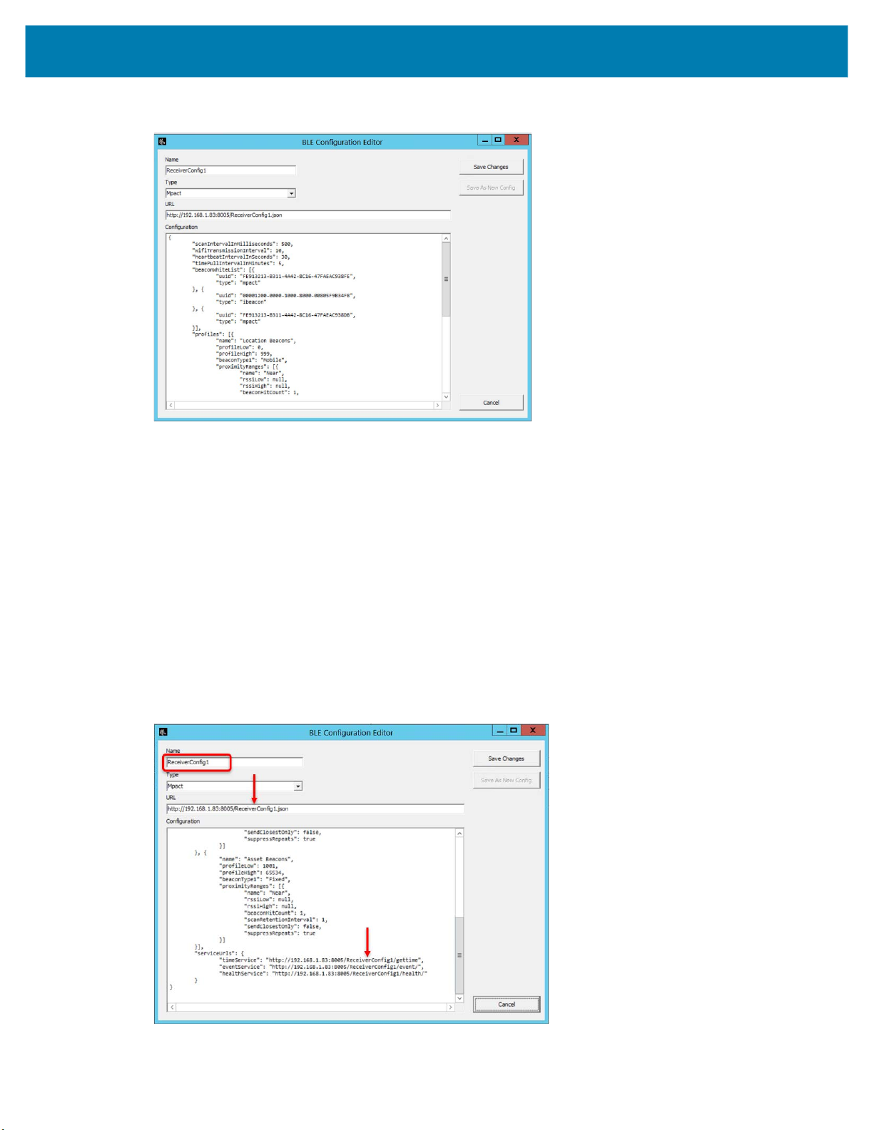
In the Name field, enter a unique name for the configuration file, such as ReaderConfig1.
4.
5. In the Type drop-down list, select a type of receiver: Mpact or Aruba.
Select Unknown for other types or if you don’t know the type. Selecting the correct type helps the ZLA
process data more effectively.
6. In the URL input box, copy and paste the value of the receiverConfigURL field from the
badge_config.json bootstrap file. See Appendix: BLE Receiver Configuration on page 63 for details.
For example, this value could be:
http://192.168.1.83:8005/ReceiverConfig1.json
The IP address in the URL above is the IP address of the ZLA. Port 8005 must be open on the ZLA.
ReceiverConfig1.json is the name of the configuration file to be retrieved by the receiver.
7. In the Configuration input box, type or paste the contents of ReceiverConfig1.json (see the sample
ReceiverConfig.json in Appendix: BLE Receiver Configuration on page 63). Note that the name of
the configuration file in the URL must be included in each of the serviceUrls as shown in the figure
below:
31
Page 32

MWE Configuration Guide
Click Save Changes. At this point your newly created ReceiverConfig1.json will be listed in the BLE
8.
Receiver Configuration window:
9. Click OK. You can similarly create multiple ReceiverConfig.json files. You are free to give these files
meaningful names of your choosing, but each name must be unique.
You should now be able to select a receiver configuration file for each BLE receiver that you add in
System Builder.
This section describes the Calibration Beacon field in the receiver properties window shown above. As
mentioned earlier, one can use a set of fixed BLE beacons at a site to locate mobile receivers.
However, as mentioned in the next section, one can also use a set of fixed receivers to locate mobile
beacons. In this latter case, using a calibration beacon can increase locate accuracy.
A calibration beacon is a BLE beacon placed at a fixed distance from a fixed receiver (check with Zebra
for the correct distance). This beacon should be configured with the same power settings as the mobile
beacons to be tracked and located. This allows the location algorithm to know the intensity of the BLE
beacon signal at a given distance from the BLE receiver.
NOTE: BLE beacon power and other settings are configured using an Android mobile application
discussed in separate documentation.
32
Page 33

MWE Configuration Guide
To add a Calibration Beacon in System Builder, simply add a BLE beacon as explained in Adding BLE
10.
Beacons on page 27. Then you will be able to select it in the Calibration Beacon drop-down list in
the receiver properties window:
Locating with BLE Beacons and BLE Receivers
We have described in the two previous sub-sections how to add infrastructure BLE beacons and BLE
receivers to the system using the System Builder tool. This section describes location algorithms
supported for various combinations of BLE beacons and receivers.
First a note on nomenclature:
• An infrastructure or fixed beacon or receiver is a beacon or receiver that is installed at a fixed position at
a site and is added in System Builder as part of the site’s location infrastructure.
• And asset or mobile beacon or receiver is a beacon or receiver that can move around a site and is
being tracked and located by the infrastructure or fixed beacons and receivers.
Secondly, the different algorithms involving BLE beacons and receivers are enabled/disabled via
checkboxes in the ZLP Host Properties window:
33
Page 34

MWE Configuration Guide
The table below presents some possible deployment scenarios and the supported location algorithms. It
also indicates what checkbox to check in the ZLP Host Properties window to enable the algorithms.
Deployment Scenario Supported Location Algorithms
You would like to locate
mobile receivers using fixed
beacons.
Presence
Mobile receivers are located using fixed
beacons and the Presence algorithm,
that is, a mobile receiver is reported to be
at the x,y coordinates of the closest fixed
beacon.
Full locate
In this case, mobile receivers are located
using fixed beacons and the MLE
(Maximum Likelihood) algorithm. This
algorithm first attempts a trilat solution
(on a plane), then a bilat solution (on a
line), then a Presence solution (x,y set
equal to closest fixed beacon), in that
order. If the algorithm can calculate a
trilat solution, it will report it; otherwise it
will attempt a bilat solution. If it can’t
obtain a bilat solution, it will use a
Presence algorithm.
NOTE: When MLE is enabled,
mobile beacons in the vicinity of
mobile receivers that have been
located by MLE will be reported at the
same location as the mobile receivers. In
other words, mobile beacons will
automatically be located using the mobile
receivers of known location and a
Presence algorithm.
Option to select in ZLP
Host Properties Window
This is the default
algorithm. No option needs
to be selected in the ZLP
Host Properties window.
Select Maximum
likelihood…
34
Page 35

MWE Configuration Guide
Deployment Scenario Supported Location Algorithms
You would like to locate
mobile beacons using fixed
receivers.
You would like to locate
Coffey tags (WhereNet tags
with built-in BLE scanner)
using fixed beacons.
Presence
Mobile beacons are reported to be at the
x,y coordinates of the closest fixed
receiver.
Full locate
In this case, mobile beacons are located
using fixed receivers and the MLE
(Maximum Likelihood) algorithm. This
algorithm first attempts a trilat solution
(on a plane), then a bilat solution (on a
line), then a Presence solution (x,y set
equal to closest fixed beacon), in that
order. If the algorithm can calculate a
trilat solution, it will report it; otherwise it
will attempt a bilat solution. If it can’t
obtain a bilat solution, it will use a
Presence algorithm.
Presence
In this scenario, Coffey tags (WhereNet
tags with a built-in BLE scanner) are
located by fixed beacons using Presence,
that is, a tag will be reported to be at the
x,y position of the closest fixed beacon.
Option to select in ZLP
Host Properties Window
Select Presence
algorithm to locate
mobile BLE beacons
Select Maximum likelihood
Select BLE Processor
Adding DART Hubs
A DART hub receives DART tag blinks from various DART sensors connected to it, runs the configured
location algorithms, and generates locate packets (tag blinks with x,y coordinates) that are made available
via a TCP port for other applications to consume. A ZLA can connect to this port, retrieve the DART blinks,
optionally apply filtering, and forward them to the MWE server.
For a ZLA to connect to a DART hub, the hub needs to be added in System Builder. To do so, you can so
one of the following:
• Click Darthubs in the tree-view, then right-click in the middle pane, and select Add Darthub from the
popup menu:
• Right-click anywhere on the map window where you would like to place a DART hub, and select New >
New Darthub from the popup menu.
35
Page 36

MWE Configuration Guide
• Click the Create Darthub button on the toolbar.
In the Darthub Properties window, enter the IP address of the DART hub and click OK.
Adding Passive RFID Readers
Passive RFID readers scan and capture data from passive RFID tags near the readers, including the ID of
reader and antenna capturing the data, the tag ID, and other encoded tag data. The ZLS Service on the
ZLA gets this tag data across the network from the readers, assigns the x,y coordinates to the tag data per
the antenna ID in the site.json file, and optionally applies data filters configured in the site.json file.
Finally, the ZLS Service forwards the data to the MWE server.
This section describes the basic steps to add an RFID Reader in System Builder. For more details, please
consult the VSS 4.2 Support for Passive RFID Tags rev.1.2 document available from Zebra Product
Support.
Typically, a passive RFID reader will require two configuration files, usually named ADD_ROSPEC.xml and
SET_READER_CONFIG.xml. If you are planning to also read the User Memory block on a passive RFID tag,
you will need a third configuration file typically named ADD_ACCESSSPEC.xml.
The parameters controlled by these configuration files will not be discussed here; it is assumed that the
user has some basic familiarity with passive RFID readers and configuration files. It is possible to load
multiple configuration files into System Builder and then assign them to passive RFID readers defined in
System Builder.
36
Page 37

MWE Configuration Guide
To load passive RFID reader configuration files in System Builder, click the Manage RFID Reader
1.
Configs button on the toolbar, shown in the figure below.
This opens the RFID Reader Configuration window.
2. Click Import From File, browse to the file you want to load (ADD_ROSPEC.xml in the example below),
optionally edit it, and then click Save As New Config.
You can repeat the above steps for SET_READER_CONFIG.xml and additional versions of these two
configuration files. The RFID Reader Configuration window will show a list of the configuration files that
have been loaded into System Builder:
37
Page 38

MWE Configuration Guide
If you are planning to read the User Memory block on a passive RFID tag, you must add an
ADD_ACCESSSPEC.xml configuration file.
38
Page 39

MWE Configuration Guide
To add a passive RFID reader in System Builder, select the RFID Readers item in the tree-view,
1.
right-click in the middle pane and select Add RFID Reader from the popup menu:
The RFID Reader properties window opens.
The RFID Reader properties window has two tabs, namely, RFID Identity and Antennas, as seen in the
figure above. In the RFID Identity tab, the following parameters are required:
• IP address
• Model: the drop-down list shows the RFID reader models currently supported. Most of the times
selecting Generic Reader will suffice for any RFID reader supporting the LLRP protocol.
• Coordinates (x,y) for the reader body (not antennas). You can type in the x,y coordinates, or you can
drag the RFID Reader icon on the map to the desired position.
• A SET_READER_CONFIG file. A single such file can be selected per reader.
• At least one ROSpec file
• At least one Access Spec file if you would like the reader to read a tag’s User Memory block
Optionally, commands and configuration parameters can be entered in the Defines section for each
reader.
39
Page 40

MWE Configuration Guide
The figure below shows the Antennas tab:
Each antenna entry in the Antennas page can be edited by double-clicking on the corresponding line.
Enable as many antennas as are connected to the reader and make sure to enter the correct x,y,z for each
antenna. Optionally, antenna commands or configuration parameters can be entered in the Antenna
Defines section for each antenna. Click OK once you have entered all required information.
You can add as many additional RFID Readers on each map as necessary. When you publish, all devices
that you have added will be shown in the Config > Hardware Devices page in the web client.
Adding Gemini Devices
Zebra’s Gemini is a software module that consumes location data from certain devices, such as Zebra BLE
beacons and receivers, and can forward it to a Kafka server in a predefined json format (Gemini format). In
this context, such devices are sometimes referred to as Gemini devices. Please see the Gemini
documentation for details on configuring the Gemini software.
The ZLA in the MWE system can read data from the Kafka topic being populated by Gemini on a specified
server, process it, and forward it back to the MWE Linux server as standard tag blink locate packets.
Therefore, the Gemini data will be displayed in the MWE web client reports and map, be available via the
MWE REST API and Camel interface, be used to define rules in the Business Rules Engine, and more.
40
Page 41

MWE Configuration Guide
To add a Gemini device in System Builder, click in the Geminis item in the tree-view, then right-click on
the middle pane and select Add Gemini from the popup menu:
This opens the Gemini Properties window:
The info provided in this window is used by the ZLA to retrieve Gemini data from the specified Kafka server
and Kafka topic.
Kafka Brokers Enter the IP address of the server hosting the Kafka topic being populated by
Gemini and the port where Kafka is listening. The format is
IP_Address:Port
as shown in the figure above. The IP address will normally be the IP address
of the MWE Linux server, but it could be of any server hosting a Kafka
instance. The Kafka port is typically 9092, and it will be 9092 for Kafka hosted
on the MWE Linux server. It is possible to specify several kafka servers by
entering:
IPAddress1:Port1,IPAddress2:Port2
Input Sensing Topic Enter the name of the Kafka topic being populated by Gemini. This name can
be configured in a Gemini configuration file; please see the Gemini
documentation for details. In figure above, for example, the name of this topic
is
mwe.sensing.device.
X,Y,Z Coordinates These coordinates are for information purposes only and are optional, as the
server hosting Gemini can be a remote server and the location of this server
has no bearing on the data being reported by Gemini. If you leave these
coordinates blank, System Builder will default them to 0.
41
Page 42

MWE Configuration Guide
NOTE: Gemini devices, as well as Zebra CLAS servers and Cisco MSE servers, are supported in System
Builder version 3.0.1 and later. If you don’t see these items in the System Builder tree-view, please
double-click the Site entry at the top of the tree-view to open the Change Site Attributes window, and
verify that the desired devices are selected, as shown in the figure below.
Adding CLAS Servers
Zebra’s ATR CLAS (Configuration, Location Analytics Software) is a server software module that collects
data from ATR RFID readers and can post this data to a remote Kafka server, using the default topic name
rtls.tag_location_update.v2.json. Refer to the the CLAS documentation for details on configuring the
CLAS software.
The ZLA in the MWE system can read data from the Kafka topic being populated by CLAS on a specified
server, process it, and forward it back to the MWE Linux server as standard tag blink locate packets.
Therefore, the ATR RFID reader data will be displayed in the MWE web client reports and map, be
available via the MWE REST API and Camel interface, be used to define rules in the Business Rules
Engine, and more.
To add a CLAS server in System Builder, click on the ATR CLAS item in the tree-view, then right-click in the
middle pane and select Add ATR CLAS from the popup menu:
42
Page 43

MWE Configuration Guide
This opens the ATR CLAS Properties window:
The info provided in this window is used by the ZLA to retrieve CLAS data from the specified Kafka server
and Kafka topic.
Kafka Brokers Enter the IP address of the server hosting the Kafka topic being populated by
CLAS and the port where Kafka is listening. The format is
shown in the figure above. The IP address will normally be the IP address of
the MWE Linux server, but it could be of any server hosting a Kafka instance.
The Kafka port is typically 9092, and it will be 9092 for Kafka hosted on the
MWE Linux server. It is possible to specify several kafka servers by entering:
IPAddress1:Port1,IPAddress2:Port2
IP_Address:Port as
Input Sensing Topic Enter the name of the Kafka topic being populated by Gemini. By default,
CLAS posts data to a Kafka topic named
rtls.tag_location_update.v2.json
X,Y,Z Coordinates These coordinates are for information purposes only and are optional, as the
server hosting CLAS can be a remote server and the location of this server has
no bearing on the data being reported by CLAS. If you leave these coordinates
blank, System Builder will default them to 0.
CLAS Server URL,
User Name, and
Password
These parameters are optional. If provided, and if the CLAS version is 2.2.28 or
higher, then the ZLA will automatically contact the CLAS server and supply the
Kafka Brokers and Input Sensing Topic values entered in the ATR Properties
window so that CLAS posts data to the specified Kafka server and Kafka topic.
If the CLAS Server URL, User Name, and Password are not provided in the ATR CLAS Properties window,
or the CLAS server is running a version lower than 2.2.28, then the following parameters must be manually
configured in the rtls.conf configuration file on the CLAS server:
location_endpoint_addr = <MWE-LinuxServer-IP>:9092
location_endpoint_topic = rtls.tag_location_update.v2.json
location_analytics_site_id = <MWE-MapID>
Where <MWE-MapID> is the id of the Map in MWE, and where the blinks should be posted. This MapID
can be read from the MapID column in the Tags report in the MWE web client.
The CLAS service must be restarted for changes in rtls.conf to take effect. Refer to the CLAS
documentation for more details on configuring the CLAS software.
43
Page 44
Adding Cisco MSE
MWE can consume and process locate data generated by one or more Cisco MSE’s. A Cisco MSE is
added to MWE by simply specifying the URL (REST API URL) and login credentials for the MSE in System
Builder. The map file, map name, and map calibration used by MWE and MSE must be the same. The
origin of the coordinate systems in MWE and MSE, however, can be different. MWE will automatically
convert the x,y coordinates received from the MSE system to the MWE coordinate system.
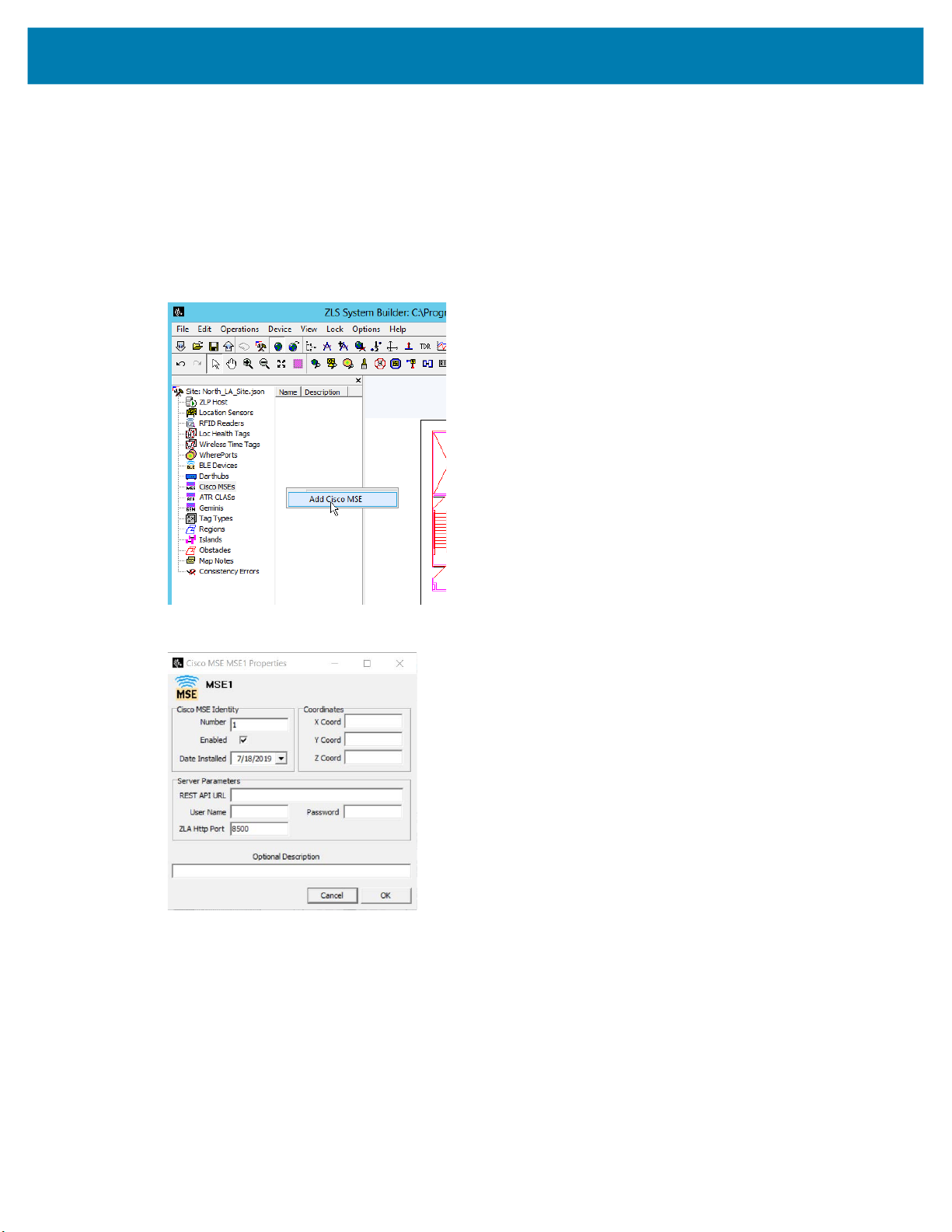
1. To add a Cisco MSE device in System Builder, click on the Cisco MSE item in the tree-view, then
right-click on the middle pane and select Add Cisco MSE from the popup menu:
MWE Configuration Guide
The Cisco MSE Properties window opens:
2. Provide the API URL and login credentials for the Cisco MSE.
Adding WhereLan III Sensors
This section describes how to add a couple of WhereLan III sensors (also known as WLN3 or G3 sensors),
which detect and process transmissions from WhereTags (a particular type of RFID tag from Zebra
Technologies).
44
Page 45

MWE Configuration Guide
To add a G3 sensor, you can right-click on the spot on the map where you want to place the G3 sensor,
1.
and select New > New WLN3 Sensor from the popup menu.
A WLN3 Sensor icon will be shown on the map where you right-clicked, and LS1 (for Location Sensor
#1) will be shown in the lists of Location Sensors in the middle pane.
2. Drag the sensor icon to the desired location on the map.
45
Page 46

MWE Configuration Guide
Double-click on the WLN3 Sensor icon on the map or on LS1 in the middle pane.
3.
The Sensor Properties window will open.
4. Type in the sensor IP address (or otherwise select DHCP) and the sensor MAC address.
The x,y values can be manually adjusted in the Antennas tab. More details on the parameters found in
the Antennas and Time Source tabs are beyond the scope of this document and can be found in the
System Builder User Manual.
5. Click OK.
You can add as many additional sensors on each map as necessary. When publishing, all devices that you
have added are shown in the Config > Hardware Devices page in the web client.
Specifying Location Algorithms
When adding WhereLAN sensors or DVR sensors in System Builder, one or more location algorithms must
be specified. Supported location algorithms include trilateration, bilateration, presence, broadway, and
maximum likelihood. Once one or more Location Sensors have been added on a map in System Builder,
one must define locate regions and specify the location algorithms to be used in each region.
46
Page 47

Device Manager
System Builder is used to generate a site configuration file (site.json) that is consumed by a ZLA. This file
includes configuration and operational parameters for the location sensors installed at a site. A ZLA sends
configuration information to these sensors and receives tag location data from them.
MWE 2.0 supports an alternative method for adding locating devices to the MWE system in a simpler way,
directly from the Devices report in the MWE web client. This report is also referred to as Device
Manager. The picture below shows the Devices report in the MWE web client.
MWE Configuration Guide
On this page you can add, configure, and manage devices. Only passive RFID readers (FX7500, FX9600)
can be added in this page in MWE 2.0. The readers must have firmware version 3.9.16 or higher and must
have the R2C (Read to Cloud) application installed. Support for other device types will be added in future
MWE releases.
For a detailed description of the functionality available in Device Manager, refer to the Device Manager
User Guide.
47
Page 48

Defining Zones
When tracking and locating an asset, we typically want to know not only the x,y coordinates, but also the
name of zones or locations where that asset is and has been. In MWE 2.0, zones are defined in the
Infrastructure > Site Manager page. Click on a map in the tree-view and then click on the
Configure Zones tab in the map window. Note that the map must be calibrated before you can define
zones.
MWE Configuration Guide
Hover over each tool on the toolbar to display a tooltip indicating the tool function. The tools are intuitive to
use and can be learned quickly by simply trying them. The Publish/Save Zones tool-button offers two
options: Save to Staging saves zones without publishing to MWE in case you want to continue to work
on the zones later, while Publish Zones publishs the zones and that become visible and active in MWE.
48
Page 49

MWE Configuration Guide
Configuring Authentication Modes
MWE supports the following authentication modes for accounts logging into the MWE web client and MWE
configuration tools.
Database In this mode, login accounts are created and authenticated locally in the MWE
database. The default admin account created by the installation scripts is a local
database account.
LDAP When this mode is selected, login accounts are authenticated against a LDAP
server on the network. Active Directory authentication is supported under this
authentication mode. When the LDAP mode is selected, it is still possible to
specify an exception list of local database accounts that are authenticated against
the local MWE database.
ADFS In this mode, login accounts are authenticated against an ADFS server on the
network. This mode does not allow login by any local database accounts.
Database, ADFS This mode allows accounts authenticated against an ADFS server and local MWE
database accounts.
OIDC In this mode, login accounts are authenticated against an OIDC server on the
network. This mode does not allow login by any local database accounts.
When installing MWE, select one of these authentication modes. Normally one chooses Database at
installation time, as the other options require entering several configuration parameters that may not be
available at installation time.
At any time after installation, one can select and configure any of the authentication modes listed above.
This is done by updating the /root/mwe/.env configuration file on the MWE Linux server, as explained in
the following sub-sections.
Database
• Edit the .env file and set:
• Save the file and run these commands to apply the change:
• The final step is to use the Users menu item in the MWE web client to create users (login accounts),
Database, OIDC This mode allows accounts authenticated against an OIDC server and local MWE
database accounts.
AUTH_TYPE=database
# cd /root/mwe
# docker-compose up -d authsvc
user groups, and specify permissions for each user group, as explained below.
49
Page 50

MWE Configuration Guide
To create local user accounts and user groups, log into the MWE web client using the MWE admin account
and click on Users on the menu bar. This tab includes two sub-tabs or pages, namely, USER GROUPS
and USERS.
The USER GROUPS page is the place where to add user groups and specify the permissions for each
group. These groups will exist only on the local MWE database.
The USERS page is where one can create local user accounts (stored in the MWE database) and assign
them to user groups. Domain login accounts do not need to be added here.
LDAP
• Edit the .env file and set:
AUTH_TYPE=ldap
Provide valid values for the LDAP parameters in the
examples and are shown below:
LDAP_URL=ldap://192.168.30.52
LDAP_USER_BASE_DN=CN=Users,DC=CLUSTER,DC=ZEBRA,DC=COM
LDAP_SEARCH_BASE_DN=CN=Users,DC=CLUSTER,DC=ZEBRA,DC=COM
LDAP_EXCLUDE_USERS=admin,user1,user2
LDAP_DEFAULT_USERGROUP=defaultLdapUserGroup
LDAP_AD_DOMAIN=CLUSTER
LDAP_VENDOR=ActiveDirectory
LDAP_SVC_ACCOUNT_NAME=uid=Ldap.Svc,ou=People,dc=cluster,dc=wherenet,dc=com
LDAP_SVC_ACCOUNT_PASSWORD=password
.env file. Default values in .env are provided only as
50
Page 51

MWE Configuration Guide
Here is a brief explanation of some of the parameters:
LDAP_URL
LDAP_USER_BASE_DN
LDAP_SEARCH_BASE_DN
LDAP_AD_DOMAIN
LDAP_VENDOR
These four parameters should be provided by the customer’s IT
department.
This parameter can be set to ActiveDirectory or OpenLdap, depending
on the LDAP version being used.
LDAP_EXCLUDE_USERS
This is a comma separated list of local MWE local login accounts (that
is, accounts defined using the MWE web client and stored in the MWE
database) that are allowed to login when LDAP is enabled.
LDAP_DEFAULT_USERGROUP
If MWE cannot obtain from the LDAP server the user group for a
particular user, or if the obtained user group cannot be matched to an
existing MWE user group, then MWE will assign this user to the MWE
user group specified in
LDAP_DEFAULT_USERGROUP=defaultLdapUserGroup. The user will
LDAP_DEFAULT_USERGROUP. The default setting is
therefore have the MWE permissions or access level associated with
this default user group.
LDAP_SVC_ACCOUNT_NAME
LDAP_SVC_ACCOUNT_PASSWORD
These two parameters are needed only for OpenLDAP, which requires
a service account to grant access for directory search of a user’s DN
(Distinguished Name). In OpenLDAP, DN is required for the user login.
NOTE: You will see the parameter LDAP_SVC_ACCOUNT_PASSWORD in the .env configuration file only
before running the MWE installation or upgrade scripts. These scripts will remove all passwords from the
.env file and encrypt them into the vault service. Therefore, you can only enter the password in .env before
performing an MWE installation or upgrade. To change the password after installation, please run these
commands on the Linux server:
# cd /root/mwe
# ./mwe --update-openldap-password
You will be prompted to enter the password for
After providing valid values for the LDAP parameters in
LDAP_SVC_ACCOUNT_PASSWORD.
.env, save the file and run these commands to
apply the changes:
# cd /root/mwe
# docker-compose up -d authsvc
The final step is to create MWE user groups that match the names of user groups on the LDAP server. For
example, if the domain user accounts that will log into the web client belong to the LDAP user groups
Managers and Operators, then you should create the user groups Managers and Operators in MWE.
1. Log into the MWE web client using the MWE admin account.
2. Click on Users on the menu bar, and select the USER GROUPS tab.
51
Page 52

MWE Configuration Guide
Add the groups and specify the permissions granted to each group, as shown in the figure below.
3.
Don’t forget to also add the group defaultLdapUserGroup mentioned above.
ADFS
1. Edit the .env file and set:
AUTH_TYPE=adfs
2. Provide valid values for the ADFS parameters in the .env file. Default values in .env are provided only
as examples and are shown below:
ADFS_CLIENT_ID=fce8beb4-3974-4d02-a3d4-a7233343fcd8
ADFS_CLIENT_SECRET=eb4QD9L5xwJOYWB9Y4-iBTIi4YqkqBNOixVx_xm5
ADFS_DISCOVERY=https://WIN-C3V92OI2O7J.example.com/adfs/.well-known/openid-configuration/
ADFS_RELYING_PARTY_TRUST_ID=mwe-adfs
ADFS_PARSER=IsMemberOf
ADFS_IDENTITY_KEY=mail
ADFS_GROUP_KEY=memberof
The values for these parameters should be provided by the customer’s IT Department.
It should be noted that possible values for ADFS_PARSER are:
IsMemberOf (e.g. [CN=MWE,...)
groupsOnly (e.g. [MWE, ...])
tokenGroup (e.g. [zebra\MWE, zebra.lan\MWE, ...])
3. After providing valid values for the ADFS parameters in .env, save the file and run these commands to
apply the changes:
# cd /root/mwe
# docker-compose up -d authsvc
The final step is to create MWE user groups that match the names of user groups on the ADFS server. For
example, if the domain user accounts that will log into the web client belong to the ADFS user groups
Managers and Operators, then you should create the user groups Managers and Operators in MWE.
1. Log into the MWE web client using the MWE admin account.
52
Page 53

MWE Configuration Guide
Click on Users on the menu bar, and select the USER GROUPS tab.
2.
3. Add the groups and specify the permissions granted to each group, as shown in the figure below.
Database, ADFS
1. Edit the .env file and set:
AUTH_TYPE=database,adfs
2. Configure the ADFS parameters as explained in the previous section.
3. In the MWE web client, add as many local user accounts as desired (see section Database above).
4. After updating .env, save the file and run these commands to apply the changes:
# cd /root/mwe
# docker-compose up -d authsvc
5. When launching the MWE web client, you will see both the normal login screen for database accounts
and an ADFS Login button for ADFS account login.
53
Page 54

Installing a SSL Certificate
Here are the steps to install a SSL certificate on the MWE server:
• Putty into the MWE server
• Create a custom directory:
# mkdir /data/mwe/images/certs/custom
MWE Configuration Guide
• Using Putty or WinSCP, copy the certificate files (pem) to this location:
/data/mwe/images/certs/custom/
The certificates names must be server.pem, server.key and cacert.pem
• In Putty, switch to mwe user and mwe directory:
# su – mwe (if prompted for a password, it is ‘Zebra123’)
# cd /data/mwe
• Run this command:
# ./mwe --configure-secure-connection
[mwe@z21st-cent08 mwe]$ ./mwe --configure-secure-connection
-------------------------------------------
MWE secure configuration:
-------------------------------------------
Configure secure communication to MWE and between MWE/RFID Readers.
Do you want use secure connection to MWE Server (y/n): y ----> Answer y
Is DHCP used in Zebra RFID Readers (y/n): n ----> Answer y or n
In order to communication securely, MWE needs valid certificates.
The certificate can be provided in the following way:
Select certificate option:
0. Configure later by running ./mwe --configure-secure-connection (use default unsecure
settings for now).
1. The customer provides certificates based on your fully qualified domain name (FQDN)
(preferred).
2. MWE generates certificates based on your fully qualified domain name (FQDN)
3. MWE generates default certificate (based on zebramwe)
4. Cancel and keep current settings
Choose an option: 1 -----> Select option 1
54
Page 55

MWE Configuration Guide
Camel Interface and REST API
MWE provides the Apache Camel interface and a REST API for third party applications to integrate to
MWE.
Camel is a flexible and powerful interface that allows data exchange between different systems, and
provides routing and mediation rules in a variety of domain-specific languages, including Java, Scala, and
XML.
Details on the MWE Camel interface and on the MWE REST API are provided in separate documentation.
Request the latest version of these documents from Zebra Product Support.
55
Page 56

MWE Configuration Guide
Configuring Email Notifications
MWE supports sending email notifications when a system alert or a resource alert is generated by MWE.
System alerts are about the health and status of the MWE system, including tags, sensors, readers, and
the MWE server itself; these alerts are predefined in MWE. Resource alerts are defined by a user using the
Business Rules Engine provided in MWE and are based on the location and status of tags and resources.
In MWE 2.0, the information about the email server to be used for alert emails is manually entered in a
configuration file on the MWE server. In a future MWE release this information will be entered via the MWE
web client. The two sub-sections below explain how to enter the email server information for business
rules alerts and for system alerts.
Resource Alerts
The Business Rules Engine in MWE sends email notifications to the email server specified in the
/etc/zebra/mwe/conf/camel/general.properties file on the MWE server. Refer to the MWE 2.0
User Guide for details on the Business Rules Engine.
The content of the general.properties file is:
email.username=senderemail_username
email.password=senderemailpassword
email.server=smtp.example.com
email.protocol=smtp
email.port=25
email.from=senderusername@exampleServer.com
Each parameter in the file has default sample values explained below.
email.username and email.password If the email server requires an authentication account to
email.server
email.protocol
email.port
email.from
For the changes in general.properties to take effect, please run the following command on a Teminal or
Putty connected to the MWE server:
# docker restart mwe_camel_1
Device Alerts
The System Alert Settings report in the MWE web client lists the device alerts available in MWE. They
include alerts related to the health and status of tags, sensors, and readers that are part of the location
infrastructure. Information about the email server to be used for these device alert is entered in the
/data/mwe/.env file on the MWE server.
accept messages from the MWE server, provide the account
credentials here.
Name or IP address of the email server.
It can be smpt or smpts.
This is the port on the email server where to send email
messages. You should check with the customer’s IT
department.
Enter here the email address that you would like to be shown
as Sender in the email messages generated by the Business
Rules Engine
56
Page 57

MWE Configuration Guide
The configuration parameters are
al_email_host This is the name or IP address of the email server
al_email_name and al_email_address The name and email address that should be shown in the
al_email_SMTP_useSASL Enter N (default) if the email server does not require an
For changes to any of the parameters discussed above under the System Alerts section to take effect, it
is necessary to restart the Alert Notification Service on the MWE Windows server. You can do this from
Windows Services or from the MWE WT Services tool.
# su - mwe
# cd /data/mwe
# docker stop mwe_monitor_alertmanager
# docker-compose stop alertsvc
# docker start mwe_monitor_alertmanager
# docker-compose up -d alertsvc
:
Sender field of email messages
authentication account to accept messages from the MWE
server. Enter ‘Y’ if it does require it; in this case, the login
credentials need to be entered using the WT Alerts tool (see
below).
57
Page 58
MWE Configuration Guide
ZLA Median and Rate Filters
The ZLA is the device or module within MWE that receives all data from a variety of locating devices and
then forwards it to the MWE. Often the data is redundant, and it is desirable to filter it to decrease network
traffic or system load.
MWE provides median, time rate, and distance rate filters that can be defined separately for WhereNet
tags, passive RFID tags, and BLE blinks (from Coffey tags). A filter defined at the ZLA level is applied to all
tags of a type (WhereNet, RFID, BLE). The MWE User Guide explains how to apply similar filters to a
particular resource type defined by a user.
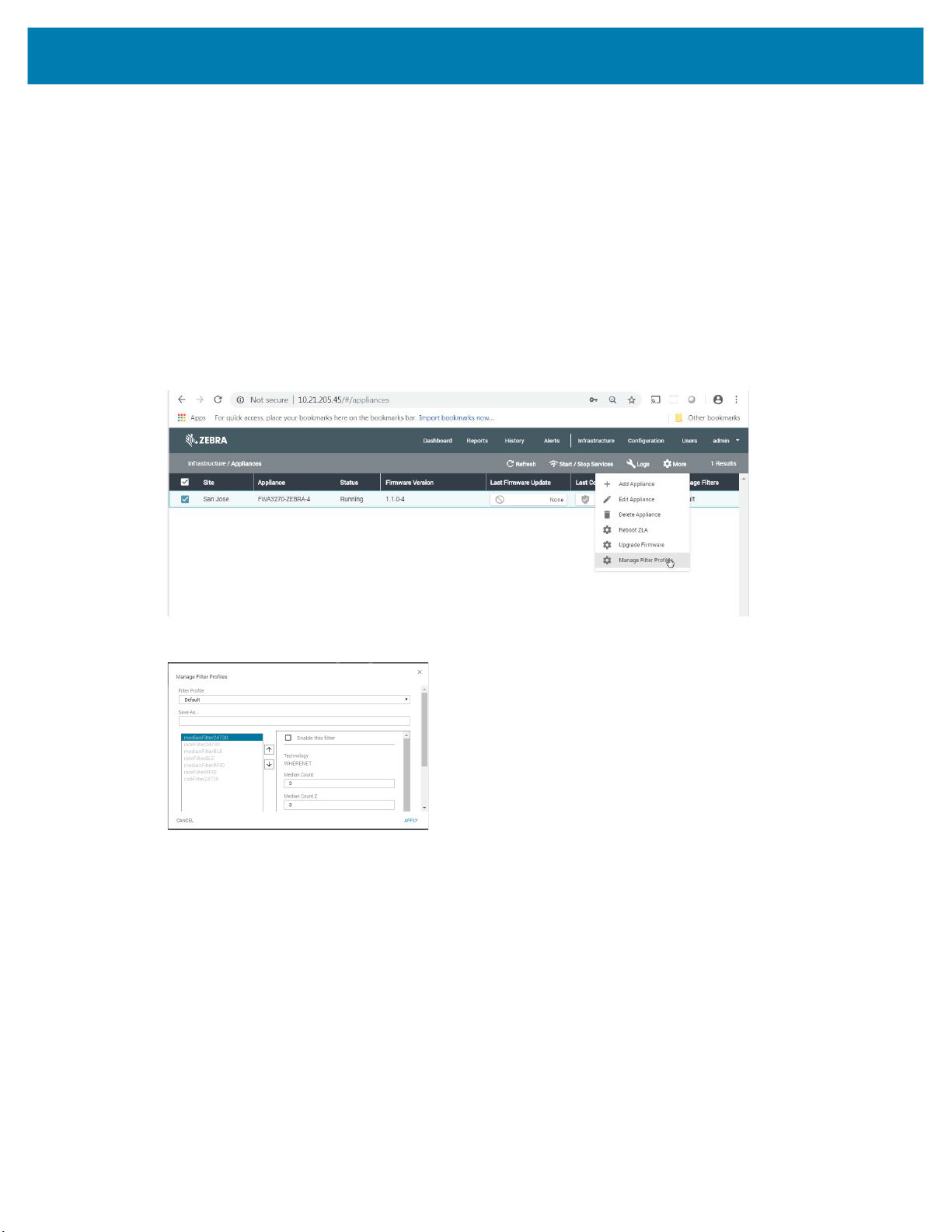
1. To define and apply a ZLA filter, launch the MWE web client and open the Infrastructure >
Appliances report.
2. Select the desired ZLA, and select More > Manage Filters from the menu bar.
The dialog window opens:
For example, if you would like to define a rate filter for WhereNet (24730) tags and passive RFID tags such
that at most one blink is allowed through every 10 seconds per tag ID.
1. To define such a filter: a. Click on rateFilter24730.
b. Check the Enable this filter checkbox.
c. Check the Do not report if less than … seconds since last report checkbox.
58
Page 59
MWE Configuration Guide
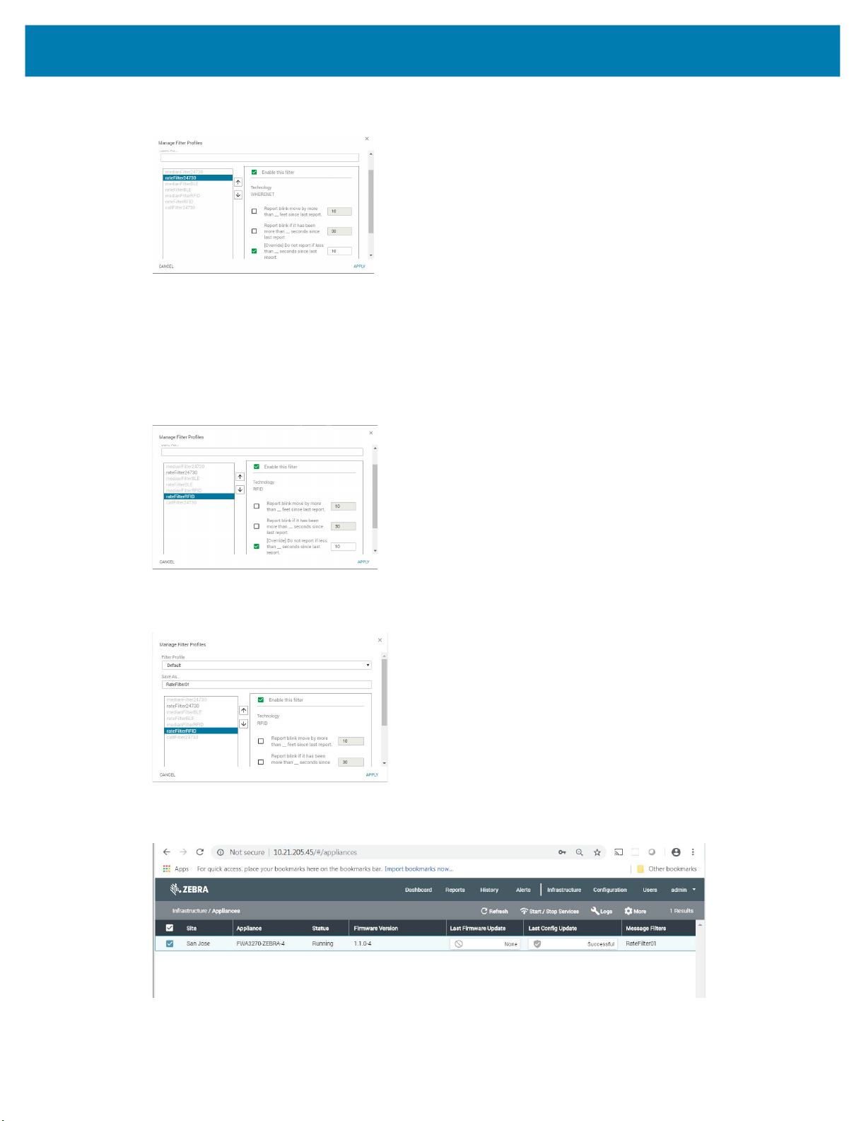
Enter 10 in the corresponding input box.
d.
2. Then: a. Click on rateFilter24730.
b. Check the Enable this filter checkbox.
c. Check the Do not report if less than … seconds since last report checkbox.
d. Enter 10 in the corresponding input box.
3. In the Save As… input box, enter a filter name of your choosing; for example, RateFilter01, and
click the Apply button.
After a few seconds, the Message Filters column in the Appliances report shows the filter being
applied:
59
Page 60

MWE Configuration Guide
To remove the filter, select the Default filter (assuming it still has its default configuration with no filters
4.
enabled), or create and apply a filter (named, for example, NoFilter) that has no filters enabled.
Currently, in addition to the Default filter, only one additional filter can be saved for future use.
For a description of how the time rate filter, distance rate filter, and median filter work, refer to the MWE
User Guide section on Resource Type Filters, where the same filters are described but are applied to
resource types defined by a user.
60
Page 61

Other Configuration Tasks
The configuration tasks described in this document are performed only once or seldom after installing the
software. After completing these configuration steps, the system should be fully functional. In particular,
the Reports > Tags page in the web client should show tag blink data with x,y coordinates being
displayed on the correct site map.
However, there are several additional configuration tasks that further customize the application or that are
performed on a frequent basis. These tasks include defining resource types, associating tags with
resources, defining data filters, configuring the various reports (columns displayed and column order), and
more. This configuration tasks are described in the MWE User Guide, which also describes the basic
functionality of the web client for end users.
MWE Configuration Guide
61
Page 62

Reference Documents
• MWE 2.0 Installation Guide
• MWE 2.0 User Guide
• MWE Camel Interface
• MWE REST API
• CLAS Server and Software Installation Guide
MWE Configuration Guide
62
Page 63
Appendix: BLE Receiver
Configuration
This appendix discusses the initialization of MPACT BLE receivers. An MPACT BLE receiver is initialized
(or bootstrapped) by downloading a bootstrap configuration file named badge_config.json. as explained
below.
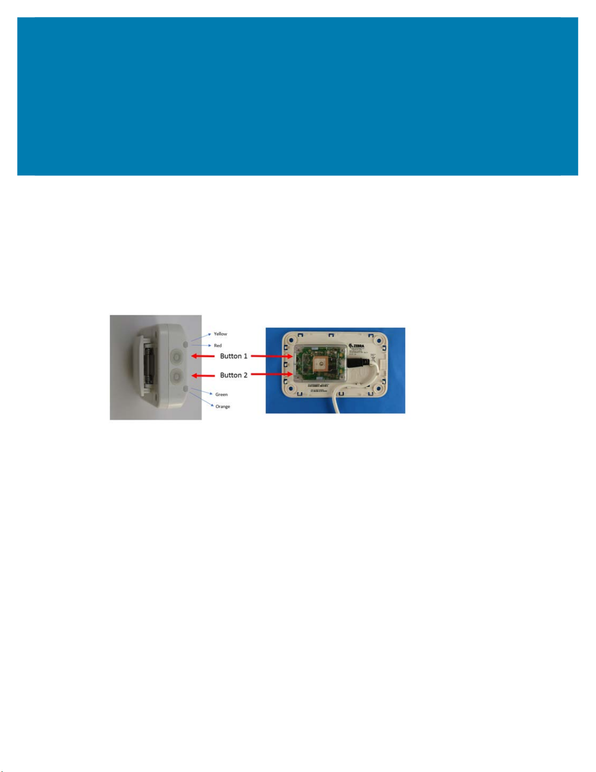
When powered up, a receiver checks its internal flash to check whether it has been initialized. If the
initialization has previously been done, it uses that configuration in flash for its operations. A receiver can
also be re-initialized at any time by pressing button 2 on the receiver for 30 to 40 seconds.
MB6000
If the receiver has not been configured previously, or it has been reset, it will act as a WIFI client and
attempt to join a WiFi network with the following parameters:
SSID mpact_init
Security Type wpa2
Security Key mpact123
Once the receiver has joined the WIFI network successfully, it will try to connect to a web server running at
the following specific IP address and port:
HTTP Server IP Address 192.168.1.100
HTTP Server Port 8005
The receiver performs a HTTP GET operation to download the bootstrap configuration file
badge_config.json.
Therefore, for a receiver to obtain its bootstrap configuration file
1. Setup a WiFi access point on a 192.168.1.x network with the parameters given above.
2. Add to this network a computer with IP 192.168.1.100 running an http server (such as a Windows
machine running MS web server), and open port 8005 on this computer.
MB5000
badge_config.json::
63
Page 64

Appendix: BLE Receiver Configuration
Place the file badge_config.json at the root of the web server. Configure the web server to serve the file
3.
via port 8005.
A sample
{
"wifiProfiles": [{
],
"gatewayConfigs": [{
}]
}
badge_config.json is given below:
"ssid": "WIFI01",
"securityKey": "1112223334",
"securityType": "WPA2",
"wpaEnterpriseUser": "",
"wpaEnterprisePassword": "",
"eapType": "",
"enable": true
}
"user": "superuser",
"password": "mpact123",
"receiverConfigURL": "http://192.168.1.83:8005/ReceiverConfig.json",
"configPullFrequencyInMins": 15,
"enable": true
Typically, the only values needed to change in badge_config.json are the ones highlighted in red color font
in the above example.
The
wifiProfiles section specifies the WiFi access point on the network that the receivers will connect to
for retrieving receiver configuration and sending data. This is the same network hosting the ZLA.
The
gatewayConfigs section specifies the IP address of the ZLA (192.168.1.83 in the example above)
from where the receiver will pull a configuration file named ReceiverConfig.json, which specifies where to
post data and other operating parameters. This file is pulled periodically with a frequency specified by the
configPullFrequencyInMins parameter.
A sample ReceiverConfig.json file is given below:
{
"scanIntervalInMilliseconds": 500,
"wifiTransmissionInterval": 10,
"heartbeatIntervalInSeconds": 30,
"timePullIntervalInMinutes": 5,
"beaconWhiteList": [{
"uuid": "FE913213-B311-4A42-8C16-47FAEAC938FE",
"type": "mpact"
}, {
"uuid": "00001200-0000-1000-8000-00805F9B34FB",
"type": "ibeacon"
}, {
"uuid": "FE913213-B311-4A42-8C16-47FAEAC938DB",
"type": "mpact"
}],
"profiles": [{
"name": "Location Beacons",
64
Page 65

Appendix: BLE Receiver Configuration
"profileLow": 0,
"profileHigh": 999,
"beaconType1": "Mobile",
"proximityRanges": [{
"name": "Near",
"rssiLow": null,
"rssiHigh": null,
"beaconHitCount": 1,
"scanRetentionInterval": 1,
"sendClosestOnly": false,
"suppressRepeats": true
}]
}, {
"name": "Asset Beacons",
"profileLow": 1001,
"profileHigh": 65534,
"beaconType1": "Fixed",
"proximityRanges": [{
"name": "Near",
"rssiLow": null,
"rssiHigh": null,
"beaconHitCount": 1,
"scanRetentionInterval": 1,
"sendClosestOnly": false,
"suppressRepeats": true
}]
}],
"serviceUrls": {
"timeService": "http://192.168.1.83:8005/ReceiverConfig/gettime",
"eventService": "http://192.168.1.83:8005/ReceiverConfig/event/",
"healthService": "http://192.168.1.83:8005/ReceiverConfig/health/"
}
}
Typically, the only values you will need to change in badge_config.json are the ones highlighted in red
color font in the above example.
A BLE receiver will process data only from BLE beacons having a UUID listed in the
beaconWhiteList
section.
The section
profiles allows a BLE receiver to apply different processing parameters to different BLE
beacons depending on the value of the beacon’s Major property, which is specified when configuring a
BLE beacon. If a beacon’s Major property falls between the values
profileLow and profileHigh for a
profile, then the BLE receiver will use that profile when processing data from the beacon.
The IP address in the
serviceUrls section is the IP address of the ZLA and tells a BLE receiver where to
get current time and where to post Beacon data (events) and receiver health and status messages. As
mentioned previously, this IP address is the only parameter you typically need to modify in the
ReceiverConfig.json file.
Next, load
configuration file published by System Builder to the ZLA, allowing the ZLA to serve
ReceiverConfig.json in System Builder, so that its content will be embedded in the site.json
ReceiverConfig.json
to BLE receivers.
65
Page 66

Appendix: BLE Receiver Configuration
The BLE Receiver Conf i g window opens:
Click Import from File to load the file.
In the URL input box, copy and paste the value of the receiverConfigURL field from
badge_config.json. In our example of badge_config.json given above, this value would be:
http://192.168.1.83:8005/ReceiverConfig.json
In the Config JSON input box, copy and paste the contents of ReceiverConfig.json:
In the Type dropdown list, select the type of receiver.
Click OK and save and/or publish the new site.json with System Builder.
66
Page 67

Appendix: BLE Receiver Configuration
The previous steps specify that the ZLA will server the ReceiverConfig.json file via port 8005 (as
indicated in the URL http://192.168.1.83:8005/ReceiverConfig.json) and therefore TCP port
8005 must be open on the ZLA. The installation package for ZLA software version 1.1.0.5 and later will
automatically open this port, but for versions 1.1.0.4 you will need to manually open this port.
To manually open TCP port 8005 on the ZLA, modify the content of the /etc/firewalld/zones/public.xml on
the ZLA. Add the line highlighted in red color font below:
<?xml version="1.0" encoding="utf-8"?>
<zone>
<short>Public</short>
<service name="dhcpv6-client"/>
<service name="ssh"/>
<port protocol="udp" port="12282"/>
<port protocol="udp" port="2496"/>
<port protocol="tcp" port="12277"/>
<port protocol="udp" port="12284"/>
<port protocol="udp" port="12273"/>
<port protocol="tcp" port="21"/>
<port protocol="tcp" port="13287"/>
<port protocol="tcp" port="12283"/>
<port protocol="udp" port="13282"/>
<port protocol="tcp" port="13283"/>
<port protocol="udp" port="13286"/>
<port protocol="tcp" port="9001"/>
<port protocol="tcp" port="12285"/>
<port protocol="tcp" port="9003"/>
<port protocol="tcp" port="8005"/>
</zone>
For the change to take effect, run the following command (in a Terminal or Putty window):
# firewall-cmd --reload
67
Page 68

www.zebra.com
 Loading...