


MPact
Indoor Beacon Toolbox
User Guide
MN-003993-02EN

Contents
Purpose ......................................................................................................................................................................... 1
Operation ......................................................................................................................................................................2
BLE NFC Toolbox .......................................................................................................................................................12
LED Blinks ...................................................................................................................................................................18
Appendix .....................................................................................................................................................................19
Supported Operating Systems ..........................................................................................................................1
Settings Screen ................................................................................................................................................3
Firmware...............................................................................................................................................3
RSSI Limit.............................................................................................................................................3
Power ...................................................................................................................................................4
Mode.....................................................................................................................................................4
Channel ................................................................................................................................................ 4
Interval .................................................................................................................................................. 4
Major.....................................................................................................................................................4
Minor.....................................................................................................................................................4
UUID ..................................................................................................................................................... 4
Save Permanent and Reload Buttons .................................................................................................. 4
Screen Menu ........................................................................................................................................ 5
Beacons Screen ...............................................................................................................................................5
Scanning...............................................................................................................................................5
Connecting the Toolbox to Beacon ......................................................................................................6
Clear Button..........................................................................................................................................6
Next Step - Details................................................................................................................................6
Detail Screen ....................................................................................................................................................7
Read Button..........................................................................................................................................8
ID .......................................................................................................................................................... 8
HW Address .........................................................................................................................................8
Firmware A, Firmware B ....................................................................................................................... 8
Model Number ...................................................................................................................................... 8
OUI – Organization Unique Identier .................................................................................................... 9
SKU – Zebra’s Part Number ................................................................................................................. 9
Cong Button ........................................................................................................................................ 9
Reboot Command ................................................................................................................................9
Upgrade Screen ..............................................................................................................................................10
Changing the Firmware in the Settings Window ................................................................................11
Settings Screen ..............................................................................................................................................12
NFC Password ...................................................................................................................................13
Channel Feature ................................................................................................................................. 13
RssiAt1M 37, RssiAt1M 38, RssiAt1M 39 ..........................................................................................13
NFC Screen .................................................................................................................................................... 13
Default NFC screen ............................................................................................................................ 13
Read Parameter Button ...................................................................................................................... 14
Cong Parameter Button .................................................................................................................... 15
Read Password Button ....................................................................................................................... 16
Cong Password Button ..................................................................................................................... 17
Broadcast Button ................................................................................................................................ 17
Sleep Button ....................................................................................................................................... 17
Clear Button........................................................................................................................................17
NFC Power Consumption ............................................................................................................................... 18
i

Purpose
This document describes using the BLE Beacon (Beacon) toolbox.
This document will address the usage of each of the three screens in the BLE Beacon Toolbox. It will go into detail on
setting up various parameters that the toolbox can set in each of the Zebra BLE Beacons (excluding the Superbeacon).
It also will address how various parameters may aect the operation of the beacon and the best way to set these values
considering the application the beacons might be deployed.
Zebra’s location solutions deploy BLE Beacons for various applications. The most common are:
y Waypoint Beacons: These Beacons are used to dene a geographical location. One might place a Waypoint
Beacon in a patient’s room in a hospital so whenever this beacon is heard by a BLE receiver, the location server will
assume that the receiver is in or near the patient’s room.
y Asset Beacons: Beacons attached to mobile assets such as carts, people, animals, tools, pallets, etc. When the
location server receives information regarding these beacons it will use the near by waypoint beacons to determine
where the asset is located.
In a warehouse, one might deploy waypoint beacons at the start and end of each isle and maybe more in between. These
waypoint beacons may all have the same UUID so that whenever the location server hears a certain UUID, it will treat it
as a xed or waypoint beacon. One might set the major eld to be unique for all the waypoint beacons in a certain isle. To
conserve battery life, the installer may set the chirp rate to a longer period to reduce the power consumption. The same is
true for Asset Beacons. The user might select a dierent UUID for assets and use the major eld to distinguish shopping
carts from mobile ladders or pallets or even handle scanners. The user may set the chirp rate for the pallet and ladder to a
longer period of time because these units don’t move as often and thus might use a smaller beacon with a smaller battery.
To control these parameters, one must use the BLE Beacon Toolbox to attach to the desired beacon, read its current
parameter settings and then change those settings if needed. The toolbox also will provide a means for updating portions of
the Beacon code over the air.
The following sections will describe in detail how to setup a BLE beacon by placing the Beacon in the connect mode and
then allowing the BLE Beacon Toolbox to connect to it to change its parameters as well as update code.
Supported Operating Systems
y Android
y iOS
Please refer to any additional documentation about Bluetooth Low Energy Products for information not covered in this
document.
1

Operation
This section will describe in detail how to use the BLE Toolbox. The BLE toolbox is not distributed as an open application. It
is only available for IOS or Android and must be downloaded from the rink.hockeyapp.net website. You will need to contact
the Location Solutions Division Product Manager to obtain a USER_ID and password to access the rink.hockeyapp.net
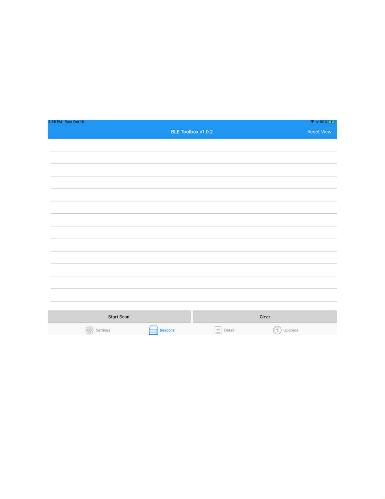
website. Once you have access to the website and the app URL you can download the BLE Toolbox app to either your iPad
or Android tablet. The screen below shows the how the BLE Toolbox app appears on an iPad once you have downloaded
the app.
The Super Beacon App also shown on this screen. There is a separate app and User’s guide for conguring the Super
Beacon. You can now launch the app to proceed to next step.
2

Settings Screen
When the BLE Toolbox application is launched, the rst window to pop up is the settings menu.
The top banner shows the version of the BLE toolbox which for this screenshot is v1.0.2. One should occasionally check the
rink.hockeyapp.net website to see if there is a newer version. The left hand column is marked Current Settings. This column
shows the parameters that can be controlled using this toolbox. Some of these settings are for controlling what the toolbox
does and some represent parameters that can be pushed to a beacon. The column on the right can be changed to reect
the new or old values being pushed to the beacon. You cannot selectively change a parameter, so if you are changing one
or more parameters, you must set the parameters you don’t want to change to be the same as those in the beacon you are
updating. This following sections discusses each setting/parameter.
Firmware
This points to rmware that the toolbox contains which can be downloaded to a Beacon. Each beacon may have one or
more versions of code which can be downloaded to the Beacon over the air (OTA). If you are not using the toolbox to
update rmware, you can ignore this setting. If you are going to update a beacon’s code, you need to set this eld to be the
code you want the toolbox to use to update the beacon. OTA programming does not change the beacon parameters.
RSSI Limit
The RSSI limit is a setting for the toolbox. This parameter is used by the toolbox to lter from the toolbox beacons that are
below a certain RSSI level. This is so that if there are numerous other beacons in the area relative to the toolbox device, the
toolbox will only pay attention to beacons whose RSSI is above the value in this eld, which in this settings screen shows
-60 dBm.
3

Power
This parameter is a beacon setting that selects the transmit power the beacon will use to transmit non-connect beacons.
Beacons support a range of power settings: most allow the user to set the power from 2 dBm to -21 dBm. This setting
represents the TX power at the radio, it does not include any antenna gain and also does not consider any pads in the RF
path. So if you set the TX power to 2 dBm and the beacon has an antenna gain of -5 dBm and a 10 dB pad, the actual TX
power at the antenna is 2 dBm + ant gain (-5dBm) + pad (-10 dBm) = -13dBm. We have provided a table a the end of this
guide to show what these values are for each beacon type.
Mode
The beacon software supports 4 dierent modes: Battery Save (1), IBeacon (2), MPACT (3), and Secure Cast (4). IBeacon
mode duplicates the Apple IBeacon packet format. MPACT mode is the same as IBeacon except that one byte of the minor
eld is used to show the battery life. The Battery Save mode supports a smaller packet over the air conserving TX on time
and helps reduce the drain on the batteries. The Secure Cast mode scrambles the MAC_ID to provide an additional security
level for the beacon packet. Setting a mode in the beacon must match the mode the BLE receiver is congured to operate in
and also the Locationing Server.
Channel
This channel variable allows the user to control which channels the beacon uses to transmit. This variable can be 0b000
to 0b111 (1-7). Bit zero represents channel 37, bit one represents channel 38 and bit 2 represents channel 39. If the bit is
set, the beacon will be sent on that channel. If the bit is cleared, the beacon will not use that channel to send a beacon.
Example: 0b010 (2) setting will have beacons only sent on channel 38.
Interval
The Interval setting is the time between beacons in msec. The value for IBeacon is 100 msec. One second would be 1000.
2500 is 2.5 seconds. The max limit on the time is 10000 msec or 10 seconds.
Major
This is a two byte eld that the user can set to whatever is desired. One strategy might be to set this number to the same
value for all Waypoint beacons in same area. Or you could set all the waypoint beacons on a given oor to the same value.
This is a valuable concept because receivers have lters which allow them to only forward beacons they hear with restricted
major elds. In this example the unique major setting for each oor helps receivers from forwarding beacons to the location
server that are not on the same oor as the receivers.
Minor
The Minor is the same type of eld as the Major. Care must be used with this eld as the MPACT mode uses this eld to
provide the receiver with battery life information. Some beacons also use the remaining byte in the minor eld to transfer
channel and version information.
UUID
This is a 16 byte eld that normally is used to identify the IBeacon format and to associate a beacon with an institution
or company like Zebra. There are ltering modes in the receivers and even the SuperBeacon that will use this eld to
control what beacons are forwarded to the location server. The UUID parameter can be set or modied in the eld directly
below the UUID variable. Normally the UUID is used to separate asset beacons from Waypoint Beacons. This is help for
debugging issues with the locationing system.
Save Permanent and Reload Buttons
These buttons are used to save or recall the saved settings. If you are programming multiple beacons, you can set up all
the parameters rst and hit the “Save Permanent” button which will save the current values in the toolbox. You can continue
to make changes to the settings and for other beacon types. Once you are nished with the minor changes, you can hit the
“Reload” button and restore the current settings to those which you saved permanently.
4
Screen Menu
The bottom banner allows the user to move from one screen to another. There are 4 screens in this toolbox. The “Settings”
button on the bottom left selects this screen that we just reviewed in this section. The “Beacons” screen is to the right of this
button which allows you to select which beacon you want to connect to for the purpose of reading or changing parameters
or updating code. The “Details” button to the right of the “Beacons” button shows the parameters of a selected beacon and
allows the user to read and write the beacon settings. The right most button “Upgrade” takes you to a screen for updating
beacon code OTA.
Beacons Screen
The Beacon screen is shown below. This screen is used to see what beacons have connected to the toolbox. You need to
connect to a beacon before you can read or write need parameters.
Right now, the screen is blank, the toolbox has not connected with any beacons. The rst step to connect the toolbox to a
beacon is to start the toolbox scanning.
Scanning
To put the toolbox in connect mode, touch the “Start Scan” button. This puts the toolbox into scan mode looking for a
beacon to connect. Next, the user needs to place the beacon in the connect mode. All our beacons enter the connect
mode by holding down the button on the beacon and watching the LED blinking. At rst, the LED blinks slowly. Releasing
the button during this slow blink period places the beacon back into beaconing mode. After the slow blink is on for about 5
second, as the user continues to hold the button down, the blink rate will change from slow to fast. When this happens, you
can remove your nger from the button and the beacon will go into connect mode. When the beacon is in the connect mode
and the toolbox is in the scan mode, the toolbox will pair with the beacon.
5

Connecting the Toolbox to Beacon
The screen shot below shows a beacon that is now connected to the toolbox. The last 3 bytes of the MAC_ID of the beacon
are shown on the left hand of the “Beacon” screen.
Notice that the “Start Scan” button has changed to “Stop Scan”. You can use this to stop the capture process if desired.
If not, you can continue to add more beacons to this list by performing the same connect button pushes described in the
previous section.
Clear Button
This button can be used to clear the beacon list on the left.
Next Step - Details
You use this step to connect one or more beacons to the toolbox prior to reading the contents or writing out new settings to
a beacon. Once you have connected to the beacon you want to read or modify, touch the ID on the left part of the screen of
the beacon you want to work with and the toolbox will take you to the “Detail” screen.
6

Detail Screen
This screen shot shows the Detail screen. This is used to read and monitor the parameters in a beacon.
On the left side of this screen you can see names of various parameters and status indicators. On the bottom banner, you
can see the buttons “Read”, “Cong”, “Reboot”, and “Stop”. Stop is not highlight because the current Beacon Status is
“Idle”. This button will highlight once one of the functions “Read”, “Cong” or “Reboot are invoked. Notice that the Beacon
Value column shows all zeros – this will change once the “Read” command is invoked. The Setting Value column displays
the values that were setup when we started with the Settings screen. These values can be changed by going back to the
Settings screen and changing the parameters on that screen.
7

Read Button
To read the parameters on the selected beacon, the user needs to touch the “Read” button. The screen below shows the
results of reading the values from the selected beacon.
This section will review these columns and what they mean. Notice that after the “Read” was completed, the middle column
became lled in and highlighted. The current Beacon Status shows “Read Done”. Below the Read Done is the column
header Beacon Value. This is separated into two parts, parameters that are xed or cannot be modied by this screen and
another Beacon Value section which has parameters that can be modied by this screen. To the right of this column is the
values we initially set in the Setting screen. Notice that the values in red are parameters read from the beacon which do not
match the parameters set in the Setting Value column. The beacon parameters will be updated to match those in the Setting
Value column when the “Cong” button is touched.
ID
This is a random number which the beacon has.
HW Address
This is the last three bytes of the MAC_ID. This beacon MAC_ID is B0:91:22:F0:19:E8.
Firmware A, Firmware B
There are two rmware images in the Beacon, an A image and a B image. This shows the version of each of these images.
Only the B image can be changed OTA. The A image can only be changed with a rmware upgrade which can only be done
in the factory.
Model Number
This is the model number of the Beacon which is “MPACT-INDR1. This is how the beacon is registered regarding Zebra’s
regulatory certications.
8

OUI – Organization Unique Identier
This is the rst 3 bytes of the MAC_ID. This block of MAC_IDs were issued to Texas Instruments who design the BLE chip
we are using. This beacon MAC_ID is B0:91:22:F0:19:E8.
SKU – Zebra’s Part Number
This eld contains the Zebra part number for this beacon. There are many SKUs for this style of beacon but all of them
share the same model number. The SKU dierence can be in the software, the pad installed on the beacon or the logo or all
three.
Cong Button
The “Cong” button is used to push the parameters shown in the Setting Value column on the right. When you invoke the
“Cong” command, the screen will be as shown below.
Notice the Beacon Status changes to “Cong_Done”. Also note that the values in the Beacon Value column now match the
values in the Setting Value column. The toolbox will reboot the beacon after it has completed the conguration operation on
the beacon. This places the beacon back into the beacon mode. You will need to go back to the scan “Beacons” screen to
re-connect to the beacon and place the beacon back into the connect mode.
Reboot Command
This button will reboot the beacon shown on the screen. Once the beacon reboots, it will come up in the beaconing mode.
You will need to go back to the scan “Beacons” screen to re-connect to the beacon and place the beacon back into the
connect mode if you wish to update the Beacon settings.
9

Upgrade Screen
The screen shot below shows the Upgrade screen.
This is rather simple. You can see in the Beacon Value column the Firmware B: is 2.0.0.0-067R-B and the Setting Value is
also 2.0.0.0-067R-B. The Setting Value is from the Setting screen. To change the rmware which is downloaded you will
need to enter a new rmware version in the Settings screen.
10

Changing the Firmware in the Settings Window
The screen shot below shows the Setting screen which you will need to use to select a version of rmware you may want to
download to a given beacon. When the user touches the rmware version on the rst line, the lower screen comes up.
This screen shot shows that the toolbox only has two versions of the beacon code. The one selected is the 067R.bin le.
Note above that the current rmware version is the 066R.bin le which is an earlier version. Beacon versions only exists as
part of the BLE toolbox. You cannot add additional beacons versions yourself. The versions only exist as part of the BLE
Toolbox. If you need a version that is not current shown as a toolbox selection, then you will need to contact the Locationing
Systems Product Manager and ask for an updated version of the BLE toolbox that includes the version you want to use as
an update.
11

BLE NFC Toolbox
This section describes how to use the BLE NFC Toolbox with NFC-enabled beacons like the MPACT-SB1100-01-WR. The
BLE NFC toolbox is only available in Android and must be downloaded from the appcenter.ms website. You will need to
contact the Location Solutions Division Product Manager to obtain a USER_ID and password to access the appcenter.ms
website. Once you have access to the website and the app URL you can download the BLE NFC Toolbox app to your
Android phone or tablet. The screen below shows the how the BLE NFC Toolbox app appears on an Android phone once
you have downloaded the app.
Settings Screen
When the BLE NFC Toolbox application is launched, the rst window to pop up is the settings menu. This window is shown
below.
The top banner shows the version of the BLE NFC toolbox which for this screenshot is v1.0.12. One should occasionally
check the appcenter.ms website to see if there is a newer version. The upper part is marked Beacon Parameters. It shows
the beacon parameters that can be controlled by both BLE and NFC using this toolbox. These parameters can be pushed to
a beacon via BLE or NFC.
The lower part is marked Extra Parameters for NFC. It shows the beacon parameters that can only be controlled by NFC.
These parameters can be pushed to a beacon via NFC.
The “Save Permanent” button can save the current parameter values to the device so when next time the app is open,
these values are loaded automatically.
The “Reload” button is to load the last saved parameter values.
The following sections discusses each parameter.
RSSI Limit, Power, Mode, Channel, Interval, Major, Minor, UUID: Please refer to section 2.1.
12

NFC Password
The NFC Password is the seed to generate a secret between the App and the NFC beacon. The secret is used during all
the read and write communications between the App and NFC beacon. The password must be 16 characters. The default
password is ZebraNFCBeacon20.
To ensure security it is recommended to create and record a new, unique password, and to update the beacons accordingly
prior to deployment.
Channel Feature
The Channel Feature setting is to enable or disable broadcasting dierent packets for channels 37, 38, 39. Value 0 means
disable. Value 1 means enable. If enabled, the dierence in the BLE packets for dierent channels are the RSSI at 1 meter
values. Enabling the Channel Feature can help improve the range/locate accuracy but will have an eect on battery life.
RssiAt1M 37, RssiAt1M 38, RssiAt1M 39
These are the Rssi at 1 meter settings for dierent channels 37, 38 and 39. When Channel Feature is enabled, they are all
eective. When Channel Feature is disabled, only the RssiAt1M 37 is eective.
NFC Screen
Default NFC screen
The default NFC screen is empty display without reading any NFC beacon.
On the bottom banner, you can see the buttons “Rd Parm” (Read Parameters), “Cfg Parm” (Cong Parameters), “Rd Pw”
(Read Password), “Cfg Pw” (Cong Password), “BDcast”(Broadcast), “Sleep”, “Clear” and “Stop”. Stop is not highlight
because there is no NFC action started. This button will highlight once one of the functions is invoked.
13

Read Parameter Button
To read the parameters on the selected beacon, the user needs to touch the “Rd Parm” button. The Beacon Status shows
“Read Done”. The screen below shows the results of reading the values from the selected beacon.
On the left side of the screen you can see names of various parameters and status indicators. “Status Parameters” shows
read-only parameters of the beacon. “Congurable Parameters” means changeable parameters.
For the “Congurable Parameters” part, the “Setting Value” column displays the values that were setup when we started
with the Settings screen. These values can be changed by going back to the Settings screen and changing the parameters
on that screen.
The parameter values under column “Beacon Value” are displayed in red when they are dierent with the values under
column “Setting Value”. After conguring and reading again, the colors will be changed to gray as others.
For Status Parameter ID, HW Address, Firmware A, Firmware B, Model, OUI, SKU, please refer to section 2.3.2 to 2.3.7.
Battery: Remaining percent of the current battery
NFC: NFC hardware is ready
14

Cong Parameter Button
To congure the parameters on the selected beacon, the user needs to touch the “Cfg Parm” button. The Beacon Status
shows “Cong Parameter Done”. The toolbox will reboot the beacon after it has completed the conguration operation on
the beacon. This places the beacon back into the beaconing mode.
The screen on left shows the results of conguring the values to the selected beacon. The screen on right shows the results
after reading parameter again.
15

Read Password Button
To read the password on the selected beacon, the user needs to touch the “Rd Pw” button. The Beacon Status shows
“Read Done”. The screen below shows the results of reading the password from the selected beacon. The “NFC Password”
row is updated. As it is dierent with the current settings, its value is displayed in red.
16

Cong Password Button
To congure the parameters on the selected beacon, the user needs to touch the “Cfg Pw” button. The Beacon Status
shows “Cong Password Done”. The toolbox will reboot the beacon after it has completed the conguration operation on the
beacon. This places the beacon back into the beaconing mode.
The screen on left shows the results of conguring the password to the selected beacon. The screen on right shows the
results after reading password again.
Broadcast Button
This button will reboot the selected beacon into the beaconing mode.
Sleep Button
This button will put the selected beacon into sleep mode. The beacon stops broadcasting and enters into low power mode.
Clear Button
This button will clear the selected beacon on the App user interface (UI).
Note: even if there is no beacon displayed on UI, user can still congure parameters and password from the current settings
to a NFC beacon by a NFC touching action.
17

NFC Power Consumption
When the NFC circuit is engaged (i.e., when the mobile device application is very close to the beacon and making a circuit)
battery power is consumed; engaging the NFC circuit for extended periods of time will reduce battery life. As battery power
is consumed over the life of the product, the eective operational range of the NFC circuit will shrink. This means physical
contact with older beacons may be required to conduct NFC communication. The speed of the NFC communications may
also be reduced with units nearing the end of its battery capacity.
It is recommended the mobile device not be in contact with the beacon for any longer than is necessary to perform the
NFC communication, and then should be removed from contact with the beacon to ensure the NFC circuit does not remain
engaged.
LED Blinks
When the NFC application interacts with an NFC-enabled beacon, its LED will ash to indicate its status. If enabled, you
may also hear a notication sound from the Android device as well as seeing the LED blink.
App/NFC Action # of LED Blinks Blink Speed
Read Parameters 1 Quick
Cong Parameters 6 Slow
Read Password 1 Quick
Cong Password 6 Slow
Broadcast 6 Slow
Sleep 2 Quick
Note • The LED blinks when the NFC circuit between the beacon and the App is broken (i.e., they are no longer connected).
If none of the App’s NFC action buttons are enabled and the App connects to a beacon’s NFC circuit a single LED blink will
occur and a notication sound on the App will sound (if NFC notication sounds are enabled) .
18

Appendix
Below are important parameters for each current Zebra Beacon SKU.
Antenna
Name SKU
Negril (ASSET) GE-MB1000-01-WR omni 1 -10 -78 -62 38EF 2000 -12 -21 -69 -21 -30 -78 2 -7 -55
Montego (Indoor GE) GE-MB2001-01-WR Patch -5 -20 -93 -77 38EF 200 -13 -38 -85 -21 -46 -93 2 -23 -70
Outdoor GE GE-MB4000-01-WR Down (red) -4.8 -10 -81 -65 38EF 200 -13 -27.8 -73 -21 -35.8 -81 5 -9.8 -55
Type
Antenna Gain (dBm)
Pad (dBm)
RSSI at 1m
RSSI at 1m
UUID Last 4 Bytes
Default Chirp (ms)
BLE Power Default
BLE EIRP Default (dBm)
BLE RSSI@1M Default (dBm)
BLE Power Min (dBm)
BLE EIRP Min (dBm)
BLE RSSI@1M Min (dBm)
BLE Power Max (dBm)
BLE EIRP Max (dBm)
BLE RSSI@1M Max (dBm)
Negril MPact
(ASSET)
Indoor MPACT-MB2000-01-WR Patch -5 0 -73 -57 38DB 100 -21 -26 -73 -21 -26 -73 2 -3 -50
Indoor MPACT-MB2001-01-WR Patch -5 -20 -93 -77 38DB 100 -11 -36 -83 -21 -46 -93 2 -23 -70
Outdoor UPS MPACT-MB4000-01-WR Down (red)
Outdoor UPS MPACT-MB4001-01-WR Side (Black)
USB_US Only MPACT-MB3000-01-WR omni -5.2 -10 -83 -67 38DB 100 -13 -18.2 -75 -21 -26.2 -83 0 -5.2 -62
USB Beacon MPACT-MB3100-01-WR omni -5.2 -10 -83 -67 38DB 100 -13 -18.2 -75 -21 -26.2 -83 0 -5.2 -62
USB Hub MPACT-MB3200-01-WR omni -5.2 -10 -83 -67 38DB 100 -13 -18.2 -75 -21 -26.2 -83 0 -5.2 -62
Negril NFC (ASSET) MPACT-SB1100-01-WR Omni 1 -10 -78 -62 38EF 2000 -13 -22 -70 -21 -30 -78 2 -7 -55
SuperBeacon MPACT-SB2000-01-WR Patch -5 0 -73 -57 38EF NA 2 -3 -50 -21 -26 -73 2 -3 -50
MPACT-MB1000-01-WR omni 1 -10 -78 -62 38DB 1000 -12 -21 -69 -21 -30 -78 2 -7 -55
-4.8 -10 -81 -65 38DB 200 -13 -27.8 -73 -21 -35.8 -81 5 -9.8 -55
Patch
-4.8 -10 -81 -65 38DB 200 -13 -27.8 -73 -21 -35.8 -81 5 -9.8 -55
Patch
19
 Loading...