

Page 1

P1051584-003 Rev. A
ebra® ZE500™ Series
Z
User Guide
Page 2

© 2014 ZIH Corp. The copyrights in this manual and the software and/or firmware in the print engin e described
therein are owned by ZIH Corp. and Zebra’s licensors. Unauthorized reproduction of this manual or the software
and/or firmware in the print engine may result in imprisonment of up to one year and fines of up to $10,000
(17
U.S.C.506). Copyright violators may be subject to civil liability.
This product may contain ZPL®, ZPL II®, and ZebraLink™ programs; Element Energy Equalizer® Circuit; E3®; and
Monotype Imaging fonts. Software © ZIH Corp. All rights reserved worldwide.
ZebraLink and all product names and numbers are trademarks, and Zebra, the Zebra logo, ZPL, ZPL II, Element
Energy Equalizer Circuit, and E
All other brand names, product names, or trademarks belong to their respective holders. For additional trademark
information, please see “Trademarks” on the product CD.
3
Circuit are registered trademarks of ZIH Corp. All rights reserved worldwide.
Proprietary Statement This manual contains proprietary information of Zebra Technologies Corporation and its
subsidiaries (“Zebra Technologies”). It is intended solely for the information and use of parties operating and
maintaining the equipment described herein. Such proprietary information may not be used, reproduced, or disclosed
to any other parties for any other purpose without the express, written permission of Zebra Technologies.
Product Improvements Continuous improvement of products is a policy of Zebra Technologies. All
specifications and designs are subject to change without notice.
Liability Disclaimer Zebra Technologies takes steps to ensure that its published Engineering specifications and
manuals are correct; however, errors do occur. Zebra Technologies reserves the right to correct any such errors and
disclaims liability resulting therefrom.
Limitation of Liability In no event shall Zebra Technologies or anyone else involved in the creation, production,
or delivery of the accompanying product (including hardware and software) be liable for any damages whatsoever
(including, without limitation, consequential damages including loss of business profits, business interruption, or loss
of business information) arising out of the use of, the results of use of, or inability to use such product, even if Zebra
Technologies has been advised of the possibility of such damages. Some jurisdictions do not allow the exclusion or
limitation of incidental or consequential damages, so the above limitation or exclusion may not apply to you.
Part Number: P1051584-003 Rev. A
Page 3

Declaration of Conformity
DECLARATION OF CONFORMITY
ZEBRA TECHNOLOGIES CORPORATION
Declares that the following Information Technology Equipment
Zebra ZE500-4 and ZE500-6
complies with the following applicable directives and standards for the
ITE: Heavy Industry environment
Applicable Directives and Supporting Standards:
2004/108/EC EMC Directive, EN55022:2010 Class A,
EN55024:2010EN61000-3-2:2006 + A2:2009, EN61000-3-3:2008,
2006/95/EC LVD Directive, EN60950-1:2006 (2nd Edition) +A11:2009 +A1:2010+A12:2011,
CB Scheme
RLAN Enabled (if equipped)
3
Applicable Directives and Supporting Standards:
99/5/EC R&TTE Directive, EN 301 489-17 V1.3.2:2008, EN 300 328 V1.8.1:2012
Manufactured for Zebra Technologies Corporation by:
Jabil Circuit (Guangzhou) Ltd No. 1 Branch Company
Lianyun Road 388, Eastern Zone,
Guangzhou Economic &Technological Development District
Guangdong Province, China
The equipment specified conforms to all Directives and Standards listed above effective
as of the date below.
Effective Date: 11 July 2012
3/27/14 ZE500™ User Guide P1051584-003
Page 4

Compliance Information
4
Compliance Information
FCC Compliance Statement
This device complies with Part 15 of the FCC rules. Operation is subject to the following two
conditions:
1. This device may not cause harmful interference, and
2. This device must accept any interference received, including interference that may cause
undesired operation.
Note • This equipment has been tested and found to comply with the limits for a Class B
digital device, pursuant to part 15 of the FCC Rules. These limits are designed to provide
reasonable protection against harmful interference in a residential installation. This
equipment generates, uses, and can radiate radio frequency energy and, if not installed and
used in accordance with the instructions, may cause harmful interference to radio
communications. However, there is no guarantee that interference will not occur in a
particular installation. If this equipment does cause harmful interference to radio or televisi on
reception, which can be determined by turning the equipment off and on, the user is
encouraged to try to correct the interference by one or more of the following measures:
• Reorient or relocate the receiving antenna.
• Increase the separation between the equipment and receiver.
• Connect the equipment into an outlet on a circuit different from that to which the receiver
is connected.
• Consult the dealer or an experienced radio/TV technician for help.
FCC Radiation Exposure Statement
(for print engines with RFID encoders)
This equipment complies with FCC radiation exposure limits set forth for an uncontrolled
environment. This equipment should be instal led and operated with minimum distance 20cm
between the radiator and your body.
This transmitter must not be co-located or operating in conjunction with any other antenna or
transmitter.
Canadian DOC Compliance Statement
This Class B digital apparatus complies with Canadian ICES-003.
Cet appareil numérique de la classe B est conforme à la norme NMB-003 du Canada.
P1051584-003 ZE500™ User Guide 3/27/14
Page 5

Contents
About This Document . . . . . . . . . . . . . . . . . . . . . . . . . . . . . . . . . . . . . . . . . . . . . . . 9
Who Should Use This Document . . . . . . . . . . . . . . . . . . . . . . . . . . . . . . . . . . . . . . . . . . . 10
How This Document Is Organized . . . . . . . . . . . . . . . . . . . . . . . . . . . . . . . . . . . . . . . . . . 10
1 • Introduction . . . . . . . . . . . . . . . . . . . . . . . . . . . . . . . . . . . . . . . . . . . . . . . . . . . 11
Print Engine Orientation . . . . . . . . . . . . . . . . . . . . . . . . . . . . . . . . . . . . . . . . . . . . . . . . . . 12
Print Engine Components . . . . . . . . . . . . . . . . . . . . . . . . . . . . . . . . . . . . . . . . . . . . . . . . 13
Control Panel . . . . . . . . . . . . . . . . . . . . . . . . . . . . . . . . . . . . . . . . . . . . . . . . . . . . . . . . . . 14
Control Panel Display . . . . . . . . . . . . . . . . . . . . . . . . . . . . . . . . . . . . . . . . . . . . . . . . . . . 15
Navigating in the Display . . . . . . . . . . . . . . . . . . . . . . . . . . . . . . . . . . . . . . . . . . . . . . 15
Changing Password-Protected Parameters . . . . . . . . . . . . . . . . . . . . . . . . . . . . . . . 18
Default Password Value . . . . . . . . . . . . . . . . . . . . . . . . . . . . . . . . . . . . . . . . . . . . . . . 18
Disable the Password Protection Feature . . . . . . . . . . . . . . . . . . . . . . . . . . . . . . . . . 18
Operating Parameters on the Control Panel . . . . . . . . . . . . . . . . . . . . . . . . . . . . . . . 19
Types of Media . . . . . . . . . . . . . . . . . . . . . . . . . . . . . . . . . . . . . . . . . . . . . . . . . . . . . . . . . 37
Ribbon Overview . . . . . . . . . . . . . . . . . . . . . . . . . . . . . . . . . . . . . . . . . . . . . . . . . . . . . . . 39
When to Use Ribbon . . . . . . . . . . . . . . . . . . . . . . . . . . . . . . . . . . . . . . . . . . . . . . . . . 39
Coated Side of Ribbon . . . . . . . . . . . . . . . . . . . . . . . . . . . . . . . . . . . . . . . . . . . . . . . . 39
2 • Printer Setup and Operation . . . . . . . . . . . . . . . . . . . . . . . . . . . . . . . . . . . . . . 41
Handling the Print Engine . . . . . . . . . . . . . . . . . . . . . . . . . . . . . . . . . . . . . . . . . . . . . . . . 42
Unpack and Inspect the Print Engine . . . . . . . . . . . . . . . . . . . . . . . . . . . . . . . . . . . . 42
Remove Additional Shipping Materials . . . . . . . . . . . . . . . . . . . . . . . . . . . . . . . . . . . 42
To Store the Print Engine . . . . . . . . . . . . . . . . . . . . . . . . . . . . . . . . . . . . . . . . . . . . . . 45
To Ship the Print Engine . . . . . . . . . . . . . . . . . . . . . . . . . . . . . . . . . . . . . . . . . . . . . . 45
3/27/14 ZE500™ User Guide P1051584-003
Page 6

Contents
6
Print Engine Installation . . . . . . . . . . . . . . . . . . . . . . . . . . . . . . . . . . . . . . . . . . . . . . . . . . 46
Requirements . . . . . . . . . . . . . . . . . . . . . . . . . . . . . . . . . . . . . . . . . . . . . . . . . . . . . . 46
Dimensions and Clearance Needs . . . . . . . . . . . . . . . . . . . . . . . . . . . . . . . . . . . . . . 47
Install the Print Engine in an Applicator . . . . . . . . . . . . . . . . . . . . . . . . . . . . . . . . . . . 52
Select a Data Communication Interface . . . . . . . . . . . . . . . . . . . . . . . . . . . . . . . . . . . . . 53
Data Cables . . . . . . . . . . . . . . . . . . . . . . . . . . . . . . . . . . . . . . . . . . . . . . . . . . . . . . . . 56
Connect the Print Engine to a Power Source . . . . . . . . . . . . . . . . . . . . . . . . . . . . . . . . . 57
Power Cord Specifications . . . . . . . . . . . . . . . . . . . . . . . . . . . . . . . . . . . . . . . . . . . . . 58
Load Ribbon and Media . . . . . . . . . . . . . . . . . . . . . . . . . . . . . . . . . . . . . . . . . . . . . . . . . . 60
3 • Printer Configuration and Adjustment . . . . . . . . . . . . . . . . . . . . . . . . . . . . . 69
Changing Printer Settings . . . . . . . . . . . . . . . . . . . . . . . . . . . . . . . . . . . . . . . . . . . . . . . . 70
Print Settings . . . . . . . . . . . . . . . . . . . . . . . . . . . . . . . . . . . . . . . . . . . . . . . . . . . . . . . 71
Maintenance and Diagnostic Tools . . . . . . . . . . . . . . . . . . . . . . . . . . . . . . . . . . . . . . 80
Network Settings . . . . . . . . . . . . . . . . . . . . . . . . . . . . . . . . . . . . . . . . . . . . . . . . . . . . 87
Language Settings . . . . . . . . . . . . . . . . . . . . . . . . . . . . . . . . . . . . . . . . . . . . . . . . . . . 91
Sensor Settings . . . . . . . . . . . . . . . . . . . . . . . . . . . . . . . . . . . . . . . . . . . . . . . . . . . . . 93
Port Settings . . . . . . . . . . . . . . . . . . . . . . . . . . . . . . . . . . . . . . . . . . . . . . . . . . . . . . . 94
Calibrate the Ribbon and Media Sensors . . . . . . . . . . . . . . . . . . . . . . . . . . . . . . . . . . . . 97
Remove Used Ribbon . . . . . . . . . . . . . . . . . . . . . . . . . . . . . . . . . . . . . . . . . . . . . . . . . . 101
Adjust the Sensors . . . . . . . . . . . . . . . . . . . . . . . . . . . . . . . . . . . . . . . . . . . . . . . . . . . . . 102
Transmissive Media Sensor . . . . . . . . . . . . . . . . . . . . . . . . . . . . . . . . . . . . . . . . . . . 102
Reflective Media Sensor . . . . . . . . . . . . . . . . . . . . . . . . . . . . . . . . . . . . . . . . . . . . . 103
Ribbon Sensor . . . . . . . . . . . . . . . . . . . . . . . . . . . . . . . . . . . . . . . . . . . . . . . . . . . . . 103
Toggle Positioning . . . . . . . . . . . . . . . . . . . . . . . . . . . . . . . . . . . . . . . . . . . . . . . . . . . . . 104
Printhead Pressure Adjustment . . . . . . . . . . . . . . . . . . . . . . . . . . . . . . . . . . . . . . . . . . . 106
4 • Routine Maintenance . . . . . . . . . . . . . . . . . . . . . . . . . . . . . . . . . . . . . . . . . . 109
Cleaning Schedule . . . . . . . . . . . . . . . . . . . . . . . . . . . . . . . . . . . . . . . . . . . . . . . . . . . . . .110
Clean the Exterior . . . . . . . . . . . . . . . . . . . . . . . . . . . . . . . . . . . . . . . . . . . . . . . . . . . . . .110
Clean the Media Compartment . . . . . . . . . . . . . . . . . . . . . . . . . . . . . . . . . . . . . . . . . . . .111
Clean the Printhead and Rollers . . . . . . . . . . . . . . . . . . . . . . . . . . . . . . . . . . . . . . . . . . .111
Replacing Print Engine Components . . . . . . . . . . . . . . . . . . . . . . . . . . . . . . . . . . . . . . . .113
Ordering Replacement Parts . . . . . . . . . . . . . . . . . . . . . . . . . . . . . . . . . . . . . . . . . . .113
Recycling Print Engine Components . . . . . . . . . . . . . . . . . . . . . . . . . . . . . . . . . . . . .113
Lubrication . . . . . . . . . . . . . . . . . . . . . . . . . . . . . . . . . . . . . . . . . . . . . . . . . . . . . . . . . . . .113
5 • Troubleshooting . . . . . . . . . . . . . . . . . . . . . . . . . . . . . . . . . . . . . . . . . . . . . . 115
Printing Issues . . . . . . . . . . . . . . . . . . . . . . . . . . . . . . . . . . . . . . . . . . . . . . . . . . . . . . . . .116
Ribbon Problems . . . . . . . . . . . . . . . . . . . . . . . . . . . . . . . . . . . . . . . . . . . . . . . . . . . . . . .119
RFID Problems . . . . . . . . . . . . . . . . . . . . . . . . . . . . . . . . . . . . . . . . . . . . . . . . . . . . . . . 120
Error Messages . . . . . . . . . . . . . . . . . . . . . . . . . . . . . . . . . . . . . . . . . . . . . . . . . . . . . . . 123
Communications Problems . . . . . . . . . . . . . . . . . . . . . . . . . . . . . . . . . . . . . . . . . . . . . . 128
P1051584-003 ZE500™ User Guide 3/27/14
Page 7

Contents
Miscellaneous Issues . . . . . . . . . . . . . . . . . . . . . . . . . . . . . . . . . . . . . . . . . . . . . . . . . . . 129
Print Engine Diagnostics . . . . . . . . . . . . . . . . . . . . . . . . . . . . . . . . . . . . . . . . . . . . . . . . 131
Power-On Self Test . . . . . . . . . . . . . . . . . . . . . . . . . . . . . . . . . . . . . . . . . . . . . . . . . 131
CANCEL Self Test . . . . . . . . . . . . . . . . . . . . . . . . . . . . . . . . . . . . . . . . . . . . . . . . . . 132
PAUSE Self Test . . . . . . . . . . . . . . . . . . . . . . . . . . . . . . . . . . . . . . . . . . . . . . . . . . . 133
FEED Self Test . . . . . . . . . . . . . . . . . . . . . . . . . . . . . . . . . . . . . . . . . . . . . . . . . . . . 134
FEED + PAUSE Self Test . . . . . . . . . . . . . . . . . . . . . . . . . . . . . . . . . . . . . . . . . . . . 137
CANCEL + PAUSE Self Test . . . . . . . . . . . . . . . . . . . . . . . . . . . . . . . . . . . . . . . . . . 137
Communication Diagnostics Test . . . . . . . . . . . . . . . . . . . . . . . . . . . . . . . . . . . . . . . 138
Sensor Profile . . . . . . . . . . . . . . . . . . . . . . . . . . . . . . . . . . . . . . . . . . . . . . . . . . . . . 139
6 • Specifications . . . . . . . . . . . . . . . . . . . . . . . . . . . . . . . . . . . . . . . . . . . . . . . . 141
General Specifications . . . . . . . . . . . . . . . . . . . . . . . . . . . . . . . . . . . . . . . . . . . . . . . . . . 142
Printing Specifications . . . . . . . . . . . . . . . . . . . . . . . . . . . . . . . . . . . . . . . . . . . . . . . . . . 143
Ribbon Specifications . . . . . . . . . . . . . . . . . . . . . . . . . . . . . . . . . . . . . . . . . . . . . . . . . . . 143
Media Specifications . . . . . . . . . . . . . . . . . . . . . . . . . . . . . . . . . . . . . . . . . . . . . . . . . . . 144
7
A • Applicator Interface Board Reconfiguration . . . . . . . . . . . . . . . . . . . . . . . 145
Tools Required . . . . . . . . . . . . . . . . . . . . . . . . . . . . . . . . . . . . . . . . . . . . . . . . . . . . . . . . 145
Changing Jumper Settings for Isolated Mode . . . . . . . . . . . . . . . . . . . . . . . . . . . . . . . . 146
Glossary . . . . . . . . . . . . . . . . . . . . . . . . . . . . . . . . . . . . . . . . . . . . . . . . . . . . . . . . 157
3/27/14 ZE500™ User Guide P1051584-003
Page 8

Contents
Notes • ___________________________________________________________________
__________________________________________________________________________
__________________________________________________________________________
__________________________________________________________________________
__________________________________________________________________________
__________________________________________________________________________
__________________________________________________________________________
__________________________________________________________________________
__________________________________________________________________________
__________________________________________________________________________
8
P1051584-003 ZE500™ User Guide 3/27/14
Page 9

About This Document
This section provides you with contact information, documen t struc ture and organization, and
additional reference documents.
Contents
Who Should Use This Document. . . . . . . . . . . . . . . . . . . . . . . . . . . . . . . . . . . . . . . . . . . 10
How This Document Is Organized . . . . . . . . . . . . . . . . . . . . . . . . . . . . . . . . . . . . . . . . . . 10
Contacts. . . . . . . . . . . . . . . . . . . . . . . . . . . . . . . . . . . . . . . . . . . . . . . . . . . . . . . . . . . . . . 27
Document Conventions . . . . . . . . . . . . . . . . . . . . . . . . . . . . . . . . . . . . . . . . . . . . . . . . . . 11
3/27/14 ZE500™ User Guide P1051584-003
Page 10

About This Document
10
Who Should Use This Document
Who Should Use This Document
This User Guide is intended for use by any person who n eeds to perform routin e maintena nce,
upgrade, or troubleshoot problems with the print engine.
How This Document Is Organized
The User Guide is set up as follows:
Section Description
Introduction on page 11 This section provides a high-level overview of the
printer and its components.
Printer Setup and Operation
on page 41
Printer Configuration and Adjustment
on page 69
Routine Maintenance on page 109 This section provides routine cleaning and
Troubleshooting on page 115 This section provides information about errors that
Specifications on page 141 This section lists general printer specifications,
Glossary on page 157 The glossary provides a list of common terms.
This section assists the technician with initial setup
and operation of the print engine.
This section assists you with configuration of and
adjustments to the print engine.
maintenance procedures.
you might need to troubleshoot. Assorted
diagnostic tests are included.
printing specifications, ribbon specifications, and
media specifications.
P1051584-003 ZE500™ User Guide 3/27/14
Page 11

Introduction
This section provides a high-level overview of the printer and its components.
1
Contents
Print Engine Orientation. . . . . . . . . . . . . . . . . . . . . . . . . . . . . . . . . . . . . . . . . . . . . . . . . . 12
Print Engine Components . . . . . . . . . . . . . . . . . . . . . . . . . . . . . . . . . . . . . . . . . . . . . . . . 13
Control Panel . . . . . . . . . . . . . . . . . . . . . . . . . . . . . . . . . . . . . . . . . . . . . . . . . . . . . . . . . . 14
Control Panel Display. . . . . . . . . . . . . . . . . . . . . . . . . . . . . . . . . . . . . . . . . . . . . . . . . . . . 15
Navigating in the Display . . . . . . . . . . . . . . . . . . . . . . . . . . . . . . . . . . . . . . . . . . . . . . . 15
Changing Password-Protected Parameters. . . . . . . . . . . . . . . . . . . . . . . . . . . . . . . . . 18
Default Password Value. . . . . . . . . . . . . . . . . . . . . . . . . . . . . . . . . . . . . . . . . . . . . . . . 18
Disable the Password Protection Feature . . . . . . . . . . . . . . . . . . . . . . . . . . . . . . . . . . 18
Operating Parameters on the Control Panel . . . . . . . . . . . . . . . . . . . . . . . . . . . . . . . . 19
Types of Media. . . . . . . . . . . . . . . . . . . . . . . . . . . . . . . . . . . . . . . . . . . . . . . . . . . . . . . . . 47
Ribbon Overview . . . . . . . . . . . . . . . . . . . . . . . . . . . . . . . . . . . . . . . . . . . . . . . . . . . . . . . 39
When to Use Ribbon . . . . . . . . . . . . . . . . . . . . . . . . . . . . . . . . . . . . . . . . . . . . . . . . . . 39
Coated Side of Ribbon. . . . . . . . . . . . . . . . . . . . . . . . . . . . . . . . . . . . . . . . . . . . . . . . . 39
3/27/14 ZE500™ User Guide P1051584-003
Page 12
Introduction
1
2 3
1
3
2
12
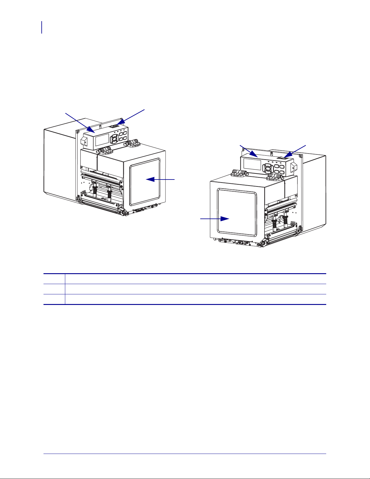
Print Engine Orientation
Print Engine Orientation
The ZE500 print engines are available in a right-hand configuration (the print mech anism is on
the right) and a left-hand configuration (the print mechanism is on the left).
Figure 1 • Left-Hand (LH) Print Engine
Figure 2 • Right-Hand (RH) Print Engine
media door
1
control panel
2
power switch
3
P1051584-003 ZE500™ User Guide 3/27/14
Page 13
Print Engine Components
3
4
910 7
5
6
12
11
8
1
2
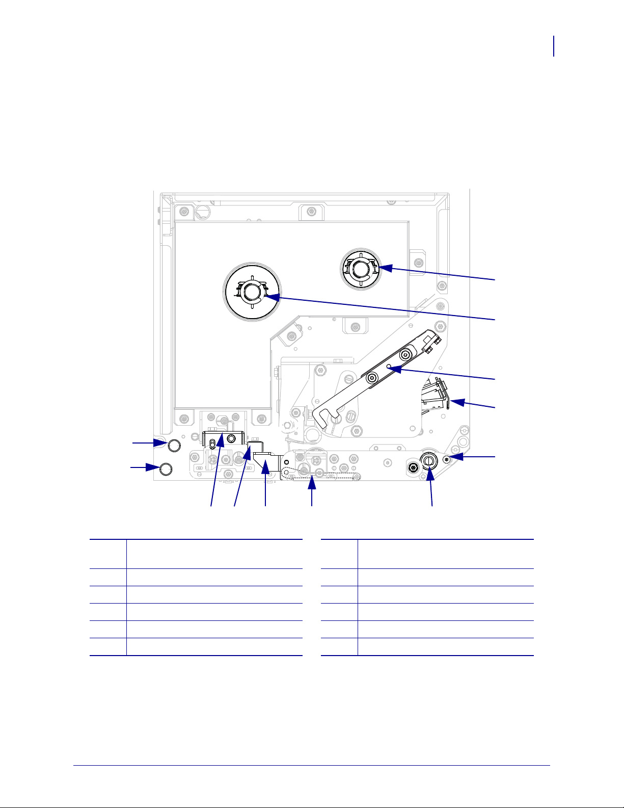
Figure 3 shows the components inside the media compartment of a right-hand print engine. A
left-hand unit contains a mirror image of these components. Familiarize yourself with these
components before continuing with the print engine setup procedure.
Figure 3 • Print Engine Components (RH model shown)
Introduction
Print Engine Components
a222
13
ribbon take-up spindle
1
ribbon supply spindle
2
printhead-release latch
3
printhead assembly (shown open)
4
peel bar
5
platen roller
6
3/27/14 ZE500™ User Guide P1051584-003
peel roller assembly (hidden when
7
closed)
peel roller latch
8
media guide
9
pinch roller assembly
10
lower guide post
11
upper guide post
12
Page 14
Introduction
POWER PAUSE STATUS DATA
1
2 3 4 5
10 11 12 13 14
6 7
9
8
14
Control Panel
Control Panel
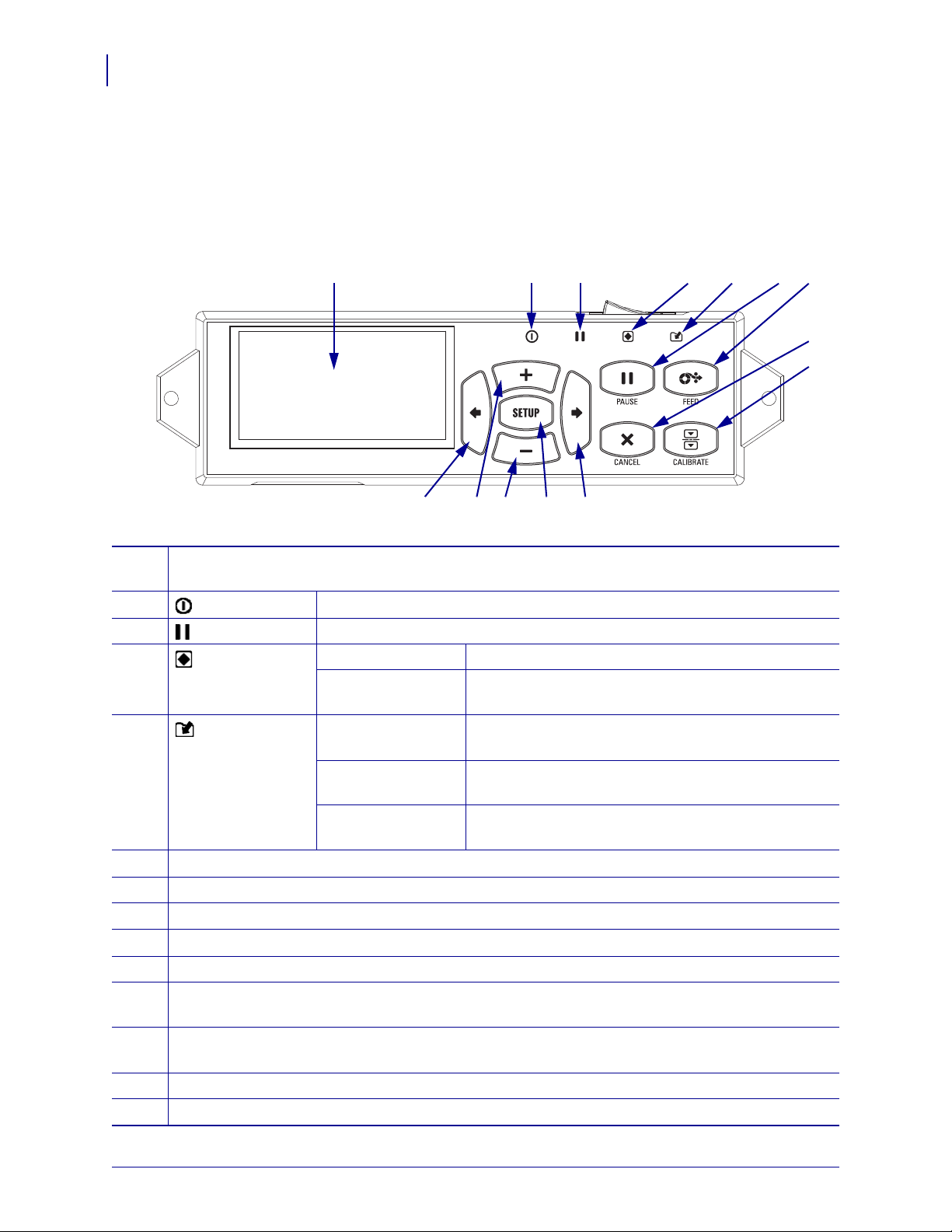
All controls and indicators for the print engine are locate d on the co ntrol pan el ( Figure 4). The
power switch is located on top of the control panel.
Figure 4 • Control Panel
The display shows the print engine’s operating status and allows the user to navigate the menu
1
system.
2
3
4
POWER light On when the print engine is on.
PAUSE light On when the print engine is paused.
STATUS light Off Normal operation—no print engine errors.
On A print engine error exists. Check the display for more
information.
5
DATA light Off Normal operation. No data being received or
processed.
On The print engine is processing data or is printing. No
data is being received.
Blinking The print engine is receiving data from or sending
status information to the host computer.
The PAUSE button starts or stops print engine operation when pressed.
6
The FEED button forces the print engine to feed one blank label each time the button is pressed.
7
The CANCEL button cancels print jobs when the print engine is paused.
8
The CALIBRATE button calibrates the print engine for media length and sensor values.
9
The LEFT ARROW navigates to the previous parameter in the menus.
10
The PLUS (+) button changes the parameter values. Common uses are to increase a value, to scroll
11
through choices, or to change values while entering the print engine password.
The MINUS (-) button changes the parameter values. Common uses are to decrease a value, to scroll
12
through choices, or to change the cursor position wh ile entering the print engine password.
The SETUP/EXIT button enters and exits configuration mode.
13
The RIGHT ARROW navigates to the next parameter in the menus.
14
P1051584-003 ZE500™ User Guide 3/27/14
Page 15
Control Panel Display
1
2
POWER PAUSE STATUS DATA
POWER PAUSE STATUS DATA
The control panel includes a display, where you can view the print engine’ s status or change its
operating parameters. In this section, you will l earn ho w to na vi gat e t hrou gh th e me nu syst em
and change values for menu items.
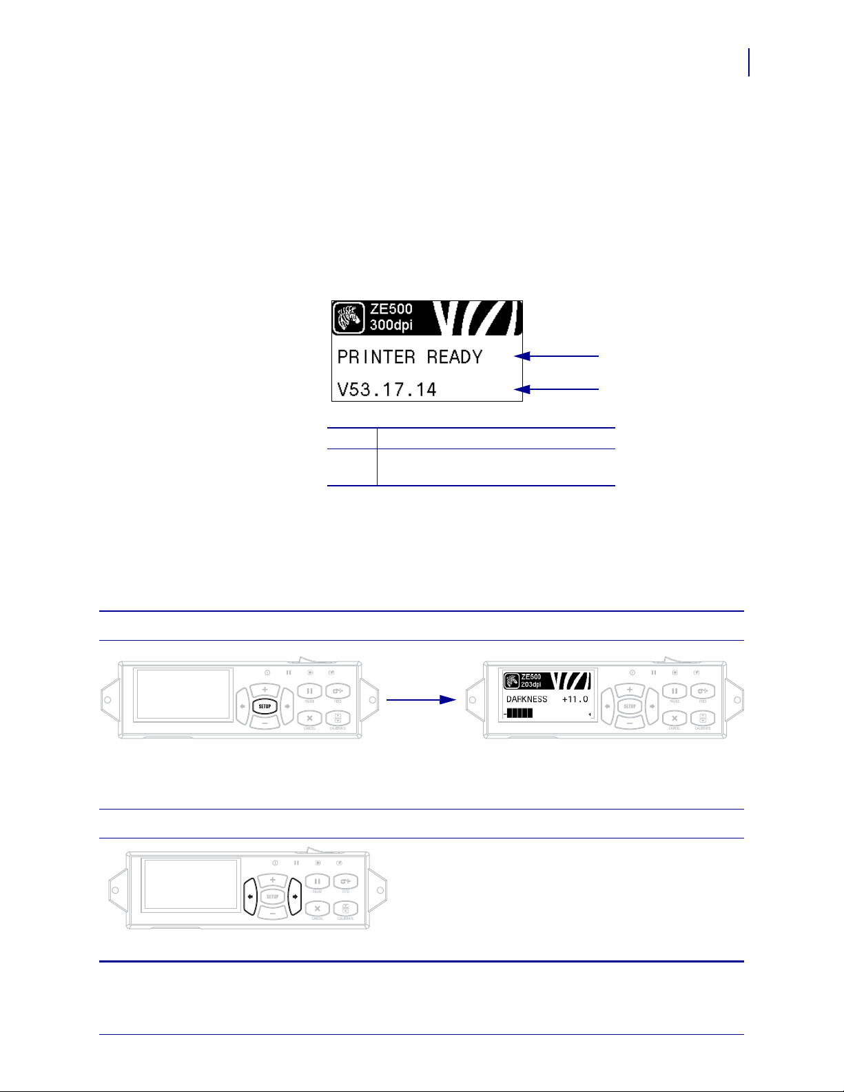
After the print engine completes the power-up sequence, it moves to the Idle Display
Figure 5).
(
Figure 5 • Idle Display
The printer’s current status
1
Information that you set through Idle
2
Display on page 86
Introduction
Control Panel Display
15
Navigating in the Display
Table 1 shows the options available for navigating through the parameters in the display.
Table 1 • Navigation
Enter Setup Mode
At the Idle Display (Figure 5), press SETUP to enter Setup Mode. The printer displays the first para meter.
Scroll through the Parameters
To scroll through the parameters, press the LEFT
POWER PAUSE STATUS DATA
ARROW or the RIGHT ARROW.
3/27/14 ZE500™ User Guide P1051584-003
Page 16
Introduction
16
Control Panel Display
Perform an action
Change Parameter Values
Table 1 • Navigation (Continued)
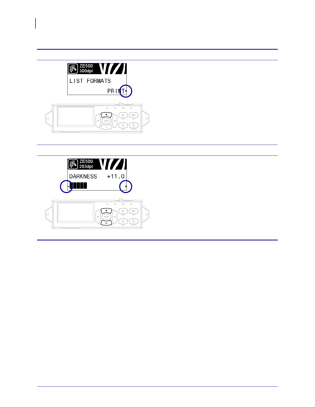
+ indicates that an action can be performed.
Press PLUS (+) to perform the specified action.
POWER PAUSE STATUS DATA
- and + indicate that a value can be changed.
POWER PAUSE STATUS DATA
Press PLUS (+) or MINUS (-) to scroll through the
accepted values.
P1051584-003 ZE500™ User Guide 3/27/14
Page 17
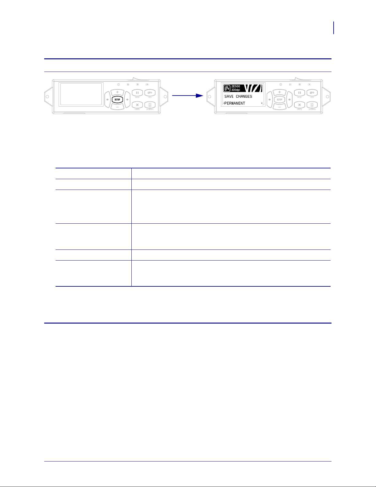
Table 1 • Navigation (Continued)
POWER PAUSE STATUS DATA
POWER PAUSE STATUS DATA
PERMANENT Stores values in the print engine even when power is turned off.
TEMPORARY Saves the changes until power is turned off.
CANCEL This option cancels all changes made since you entered Setup mode,
except for changes made to DARKNESS, TEAR OFF,
COMMUNICATION, and LANGUAGE settings, which go into effect as
soon as they are made.
LOAD DEFAULTS Use this option to restore all settings other than the network settings back
to the factory defaults. Use care wh en loading defaults because you will
need to reload all settings that you changed manually.
LOAD LAST SAVE Loads the values from the last permanent save.
DEFAULT NET Use this option to restore all print server and network settings back to the
factory defaults. Use care when loading defaults because you will need to
reload all settings that you changed manually.
Exit Setup Mode
1. While in Setup Mode, press SETUP to exit the operating parameters.
The LCD displays SAVE CHANGES.
2. To return to the parame ters, plu s the LEFT ARROW.
OR
Press PLUS (+) or MINUS (-) to scroll through the exit options.
Introduction
Control Panel Display
17
3. Press the RIGHT ARROW to select the displayed choice and exit Setup Mode.
When the configuration and calibration sequence finishes, the print engine returns to the Idle Display.
3/27/14 ZE500™ User Guide P1051584-003
Page 18

Introduction
18
Control Panel Display
Changing Password-Protected Parameters
Certain parameters, including the communication parameters, are password-protected by
factory default.
Caution • Do not change password-protected parameters unless you have a complete
understanding of the parameters’ functions. If the parameters are set incorrectly, the print
engine may function unpredictably.
The first time that you attempt to change a password-protected parameter, the print engine
displays
four-digit numeric password. After you have entered the password correctly, you do not have
to enter it again unless you leave Setup mode by pressing SETUP/EXIT or by turnin g off (
the print engine.
ENTER PASSWORD. Before you can change the parameter, you must enter the
To enter a password for a password-protected parameter, complete
steps:
these
1. At the password prompt, use MINUS (-) to change the selected digit position.
O)
2. When you have selected the digit that you wish to change, use PLUS (+) to increase the
selected digit value. Repeat these two steps for each digit of the password.
3. After entering the password, press SELECT.
The parameter you selected to change is displayed. If the password was entered correctly,
you can change the value.
Default Password Value
The default password value is 1234. The password can be changed using the Zebra
Programming Language (ZPL) command
web pages (ZebraNet wired or wireless print server require d).
^KP (Define Password) or using the print engine’s
Disable the Password Protection Feature
You can disable the password protection feature so that it no longer prompts you for a
password by setting the password to 0000 via the
password-protection feature, send the ZPL comma nd
1 to 9999.
^KP ZPL command. To re-enable the
^KPx, where x can be any number from
P1051584-003 ZE500™ User Guide 3/27/14
Page 19
Operating Parameters on the Control Panel
Items in this menu are shown in the order in which they appear when you press the RIGHT
ARROW. For more information about these settings, see
For information about RFID parameters, refer to RFID Programming Guide 2. You can
download the latest copy from
http://www.zebra.com/manuals.
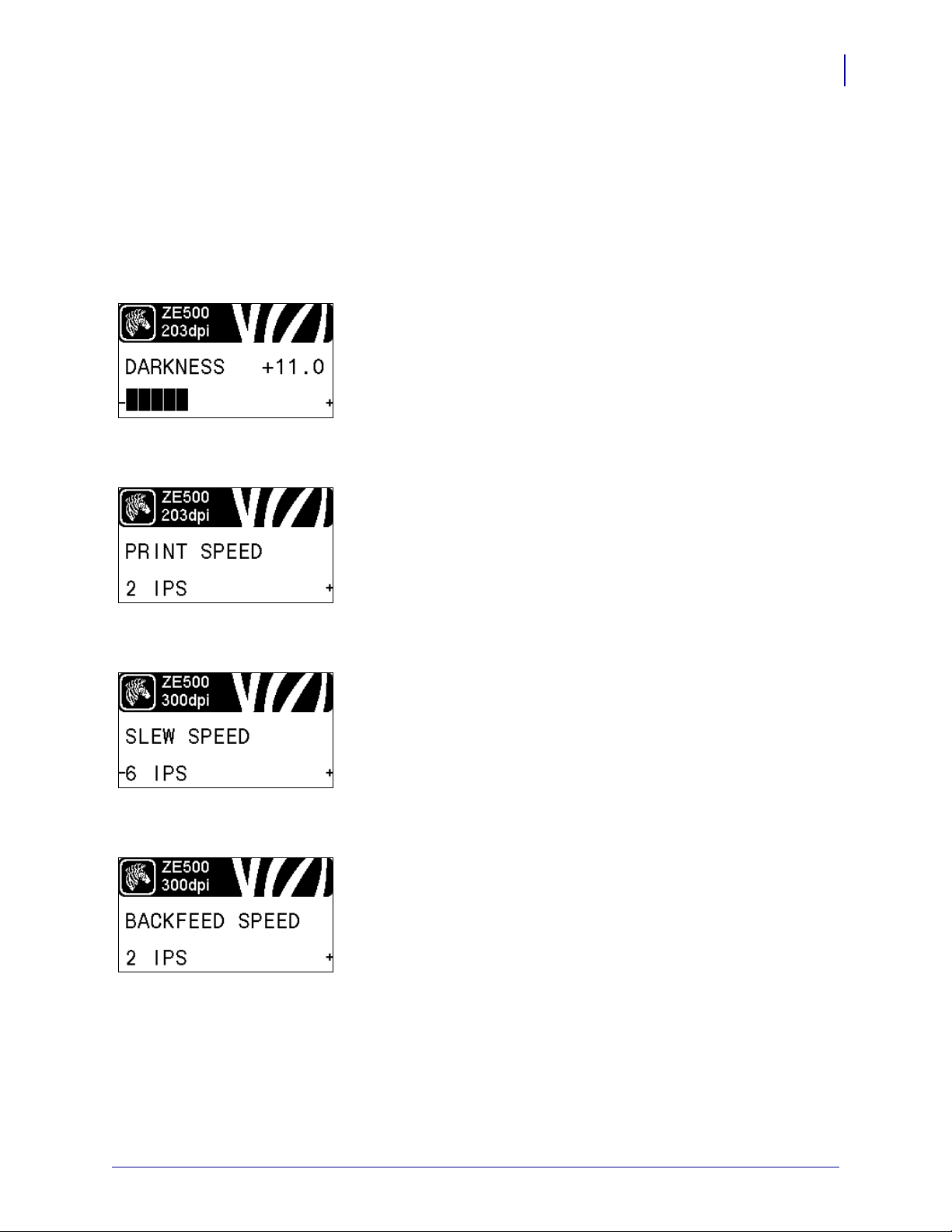
Adjust the Print Darkness
Set the darkness to the lowest setting that provides good print
quality. If you set the darkness too high, the label image may print
unclearly, bar codes may not scan correctly, the ribbon may burn
through, or the printhead may wear prematurely.
See Print Darkness on page 71 for more information.
Select the Print Speed
Introduction
Control Panel Display
Print Settings on page 71.
19
Select the speed for printing a label (given in inches per second).
Slower print speeds typically yield better print quality.
See Print Speed on page 71 for more information.
Set the Slew Speed
The slew speed is the speed at which the printer skips over the
areas in a label format that are blank across the full width of the
image. A faster slew speed may reduce printing time. The print
engine automatically senses when to apply this higher speed.
See Slew Speed on page 71 for more information.
Set the Backfeed Speed
Backfeed refers to the backward motion of the media from the tear off or peel-off position to the print position. This motion occurs so
that more of the lead edge of each label can be used for printing.
Reducing backfeed speed can mitigate some issues. In general,
reducing the backfeed speed may improve print quality at the start
of the label. This speed defaults to 2 ips.
See Backfeed Speed on page 72 for more information.
3/27/14 ZE500™ User Guide P1051584-003
Page 20
Introduction
20
Control Panel Display
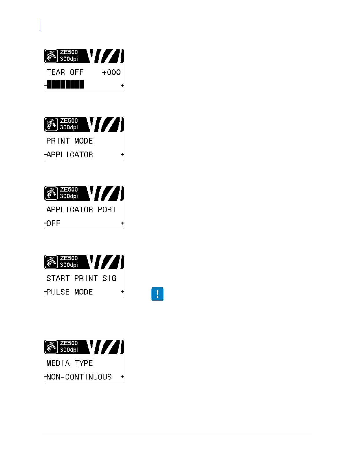
Adjust the Tear-Off Position
If necessary, adjust the position of the media over the tear-off bar
after printing.
See Tear-Off Position on page 72 for more information.
Select the Print Mode
Select a print mode that is compatible with your print engine
options.
See Print Mode on page 73 for more information.
Select the Applicator Port Mode
Select the appropriate action for the applicator port, as suggested
by the applicator manufacturer.
See Applicator Port on page 73 for more information.
Select the Start Print Signal
This parameter determines how the print engine reacts to the Start
Print Signal input on pin 3 of the applicator interface connector at
the rear of the print engine.
Important • The Start Pri nt Si gnal is determined by the
applicator manufacturer. The print engine must use the
correct setting for it to work properly.
See Start Print Signal on page 74 for more information.
Set the Media Type
Select the type of media that you are using.
See Media Type on page 74 for more information.
P1051584-003 ZE500™ User Guide 3/27/14
Page 21
Introduction
Control Panel Display
Select the Media Sensor
Select the media sensor that is appropriate for the media t hat you
are using.
See Sensor Type on page 93 for more information.
Select the Print Method
Specify if ribbon is being used. Thermal Transfer media requires
ribbon for printing while Direct Thermal media does not.
To determine if you need to use ribbon, see When to Use Ribbon
on page 39.
See Print Method on page 74 for more information.
Adjust the Print Width
21
Specify the width of the labels being used.
See Print Width on page 75 for more information.
Set the Maximum Label Length
Set the maximum label length to a value that is at least 1.0 in.
(25.4 mm) greater than the actual label length plus the interlabel
gap. If you set the value to one that is smaller than the la bel length ,
the print engine assumes that continuous media is loaded, and the
print engine cannot calibrate.
See Maximum Label Length on page 76 for more information.
Set Early Warning for Media and Ribbon
When this feature is enabled, the print engine provides warni ngs
when the media or ribbon is reaching near the end of the roll.
See Early Warning for Media and Ribbon on page 80 for more
information.
3/27/14 ZE500™ User Guide P1051584-003
Page 22
Introduction
22
Control Panel Display
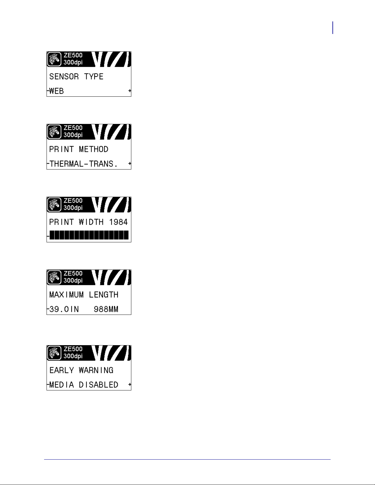
Set Number of Labels Per Roll for Early Warning
This value should correspond to the number of l abels per roll of the
media that you are using.
See Early Warning for Media and Ribbon on page 80 for more
information.
* This parameter appears only if Early Warning for Media and
Ribbon is enabled.
Reset Media Counter for Early Warning
Reset the media counter after you replace the media roll.
• If you replaced the media, press PLUS (+) to select YES.
• If you did not replace the media, press MINUS (-) to select NO,
or press the LEFT ARROW or RIGHT ARROW to move to
another parameter.
* This parameter appears only if Early Warning for Media and
Ribbon is enabled.
Set Ribbon Length for Early Warning
This value should correspond to the ribbon length for the ribbon
that you are using.
See Early Warning for Media and Ribbon on page 80 for more
information.
* This parameter appears only if Early Warning for Media and
Ribbon is enabled.
Reset Ribbon Counter for Early Warning
Reset the ribbon counter after you replace the roll of ribbon.
• If you replaced the ribbon, press PLUS (+) to select YES.
• If you did not replace the ribbon, press MINUS (-) to select
NO, or press the LEFT ARROW or RIGHT ARROW to
move to another parameter.
* This parameter appears only if Early Warning for Media and
Ribbon is enabled.
P1051584-003 ZE500™ User Guide 3/27/14
Page 23
Introduction
Control Panel Display
Set Early Warning for Maintenance
When this feature is enabled, the print engine provides warni ngs
when the printhead needs to be cleaned.
See Early Warning for Maintenance on page 80 for more
information.
Set Printhead Cleaning Interval*
When Early Warning for Maintenance is enabled, set this value to
the length of the media or ribbon roll that you are using.
See Printhead Cleaning Interval on page 80 for more information.
* This parameter appears only if Early Warning for Maintenance
is enabled.
Reset Printhead Cleaning Counter for Early Warning*
23
• If you received the message WARNING CLEAN PRINTHEAD,
clean the printhead, and then press PLUS to select
YES to reset
the Early Warning for Maintenance printhead cleaning counter.
• If you have not cleaned the printhead, press MINUS to select
NO.
* This parameter appears only if Early Warning for Maintenance
is enabled.
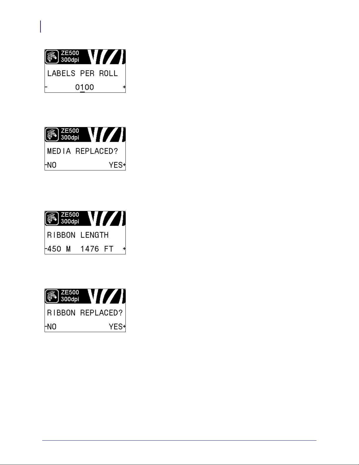
Set Printhead Life Expectancy*
When Early Warning for Maintenance is enabled, set this value to
the number of inches of media that the printhead is expected to
print.
See Printhead Life Expectancy on page 80 for more information.
* This parameter appears only if Early Warning for Maintenance
is enabled.
Reset New Printhead Counter for Early Warning*
• If you received the message WARNING REPLACE HEAD,
replace the printhead, and then press PLUS (+) to select
YES to
reset the Early Warning for Maintenance printhead replacement
counter.
• If you have not replaced the printhead, press MINUS (-) to
NO.
select
* This parameter appears only if Early Warning for Maintenance
is enabled.
3/27/14 ZE500™ User Guide P1051584-003
Page 24
Introduction
24
Control Panel Display
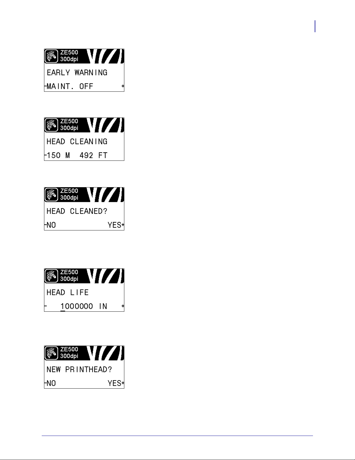
View the Non-Resettable Counter
This parameter displays the total length of media that the printer
has printed.
See Non-Resettable Counter on page 81 for more information.
View User-Controlled Counter 1
This parameter displays the total length of media that the printer
has printed since this counter was la st reset.
See User-Controlled Counters on page 81 for more information.
View User-Controlled Counter 2
This parameter displays the total length of media that the printer
has printed since this counter was la st reset.
See User-Controlled Counters on page 81 for more information.
Print Counter Readings
Prints a label that lists the odometer readings for the following:
• the non-resettable counter
• the two user-controlled counters
• the Early Warning for Maintenance counters, which indicate
when the printhead was last cleaned and the printhead life (If
the Early Warning for Maintenance feature is disabled, the
counters related to it do not print.)
See Print Counter Readings on page 81 for more information.
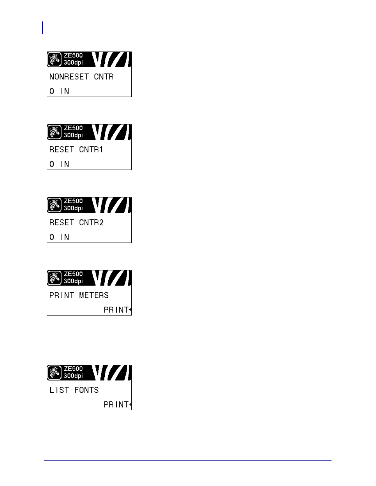
Print Font List
This option prints a label that lists the available fonts in the print
engine, including standard print engine fonts plus any optional
fonts. Fonts may be stored in RAM or Flash memory.
See Print Information on page 82 for more information.
P1051584-003 ZE500™ User Guide 3/27/14
Page 25
Introduction
Control Panel Display
Print Bar Code List
This option prints a label that lists the available bar codes in the
print engine. Bar codes may be stored in RAM or Flash memory.
See Print Information on page 82 for more information.
Print Image List
This option prints a label that lists the available images stored in
the print engine’s RAM, Flash memory, or optional memory card.
See Print Information on page 82 for more information.
Print Format List
25
This option prints a label that lists the available formats stored in
the print engine’s RAM, Flash memory, or optional memory card.
See Print Information on page 82 for more information.
Print Configuration Label
This option prints a configuration label (see Figure 12
on page 132), which lists the current print engine configuration.
See Print Information on page 82 for more information.
Print Network Configuration Label
This option prints a configuration label (see Figure 13
on page 132), which lists the settings for any print server that is
installed.
See Print Information on page 82 for more information.
3/27/14 ZE500™ User Guide P1051584-003
Page 26
Introduction
26
Control Panel Display
Print All Labels
This option prints labels that list the available fonts, bar codes,
images, formats, and the current print engine and network
configurations.
See Print Information on page 82 for more information.
Initialize Flash Memory
This option erases all previously stored information from Flash
memory.
1. If prompted for a password, enter the printer password. For
instructions, see
Changing Password-Protected Parameters
on page 18.
The display shows INITIALIZE FLASH?
2. Press PLUS (+) to select YES.
The display shows ARE YOU SURE?.
3. Do you want to continue?
• Press MINUS (-) to select NO to cancel the request and return
INITIALIZE FLASH prompt.
to the
• Press PLUS (+) to select YES and begin initialization.
When initialization is complete, the control panel displays
INITIALIZING COMPLETED.
Note • Initializing memory can take several minutes.
See Initialize Flash Memory on page 82 for more information.
Print a Sensor Profile
Use this menu item to print a sensor profile.
See Print a Sensor Profile on page 82 for more information.
Calibrate the Media and Ribbon Sensors
Use this menu item to adjust the sensitivity of the media and
ribbon sensors.
See Media and Ribbon Sensor Calibration on page 85 for more
information. For instructions on how to perform a calibration
procedure, see
Calibrate the Ribbon and Media Sensors
on page 97.
P1051584-003 ZE500™ User Guide 3/27/14
Page 27
Introduction
Control Panel Display
Set Parallel Communications
Select the communications port that matches the one being used by
the host computer.
See Parallel Communications on page 94 for more information.
Set Serial Communications
Select the communications port that matches the one being used by
the host computer.
See Parallel Communications on page 94 for more information.
Set the Baud Rate
27
Select the baud value that matches the one being used by the host
computer.
See Baud Rate on page 95 for more information.
Set the Data Bits Value
Select the data bits value that matches the one being used by the
host computer.
See Data Bits on page 95 for more information.
Set the Parity Value
Select the parity value that matches the on e be ing used by the host
computer.
See Parity on page 95 for more information.
3/27/14 ZE500™ User Guide P1051584-003
Page 28
Introduction
28
Control Panel Display
Set the Host Handshake Protocol Value
Select the handshake protocol that matches the one being used by
the host computer.
See Host Handshake on page 96 for more information.
Set the Zebra Protocol Value
Protocol is a type of error checking system. Depending on the
selection, an indicator may be sent from the print engine to the host
computer signifying that data has been received. Select the
protocol that is requested by the host computer.
See Protocol on page 96 for more information.
Set the Network ID
This parameter assigns a unique number to the print engine when
the print engine is operating in an RS422/485 multi-drop network
environment (an external RS422/485 adapter is required). This
gives the host computer the means to address a specific print
engine. This does not affe ct TCP/ IP or IPX net works. Set a uni que
network ID number for this print engine.
See Network ID on page 96 for more information.
Enable Communication Diagnostics Mode
Use this diagnostics tool to cause the printer to output the
hexadecimal values for all data received by the printer.
See Communication Diagnostics Mode on page 85 for more
information.
Set the Control Character Value
Set the control prefix character to match what is used in your label
formats.
See Control Character on page 91 for more information.
P1051584-003 ZE500™ User Guide 3/27/14
Page 29
Introduction
Control Panel Display
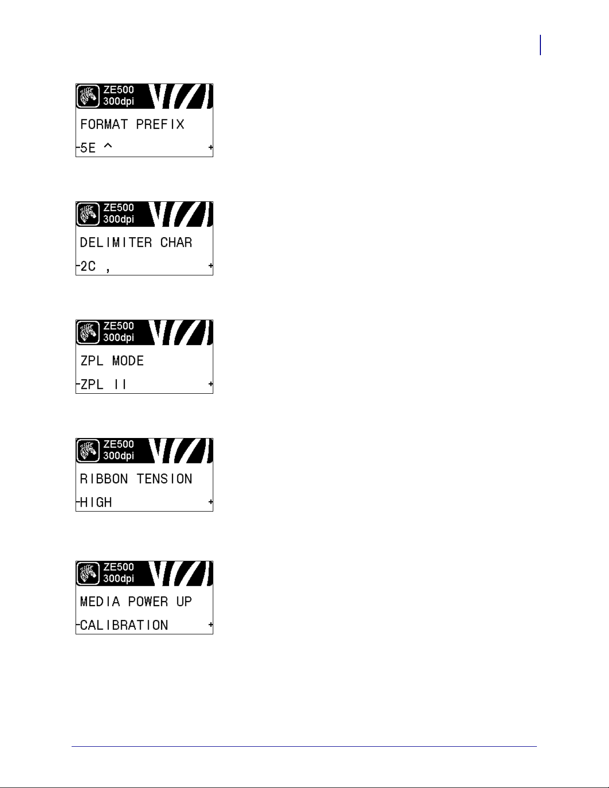
Set the Format Command Prefix Value
Set the format command prefix character to match what is used in
your label formats.
See Command Character on page 92 for more information.
Set the Delimiter Character Value
Set the delimiter character to match what is used in your label
formats.
See Delimiter Character on page 92 for more information.
Set the ZPL Mode
29
Select the ZPL mode that matches what is used in your label
formats.
See ZPL Mode on page 92 for more information.
Set the Ribbon Tension
Select the ribbon tension setting that is appropriate for the wi dth or
type of media being printed. HIGH can be used for most media.
The correct setting is determined by a combination of the ribbon
width and the ribbon length (Table 5). If necessary, use a lower
value for narrow media or for glossy media.
See Ribbon Tension on page 77 for more information.
Set the Power-Up Action
Set the action for the printer to take during the power-up sequence.
See Power-Up Action on page 83 for more information.
3/27/14 ZE500™ User Guide P1051584-003
Page 30
Introduction
30
Control Panel Display
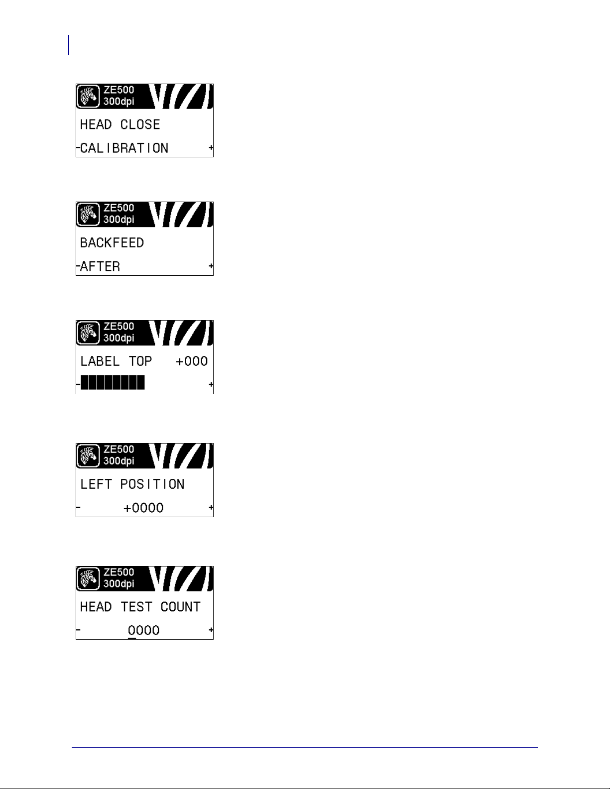
Set the Head-Close Action
Set the action for the printer to take when you close the printhead.
See Head-Close Action on page 83 for more information.
Set the Backfeed Sequence
This parameter sets when label backfeed occurs after a label is
removed in some print modes. It has no effect in Rewind mode.
This setting is superseded by ~JS when received as part of a label
format.
See Backfeed Sequence on page 77 for more information.
Adjust the Label Top Position
This parameter adjusts the print position vertically on the label.
Positive numbers adjust the label top position farther down the
label (away from the printhead) by the specified number of dots.
Negative numbers adjust the position up the label (toward the
printhead).
See Label Top Position on page 78 for more information.
Adjust the Label Left Position
If necessary, shift the print position horizontally on the label.
Positive numbers move the left edge of the image toward the
center of the label by the number of dots selected, while negative
numbers move the left edge of the image toward the left edge of
the label.
See Label Left Position on page 78 for more information.
Set the Head Test Cou nt*
The ZE500-6 print engine periodically performs a test of the
printhead functionality. This parameter establishes how many
labels are printed between these internal tests.
* This menu item appears only on ZE500-6 print engines.
P1051584-003 ZE500™ User Guide 3/27/14
Page 31

Introduction
Control Panel Display
Set Applicator Error Signal When Print Engine Pauses
When this option is enabled and the print engine is paused, the
print engine sets the applicator error state.
See Error on Pause on page 78 for more information.
Set the Ribbon Low Mode
The Ribbon Low feature determines if the print engine will
generate a warning when the amount of ribbon left on the roll gets
low.
See Ribbon Low Mode on page 79 for more information.
Set the Ribbon Low Output
31
When the Ribbon Low feature is en abled, this parameter
determines if the output signal on Pin 9 is HIGH or LOW.
See Ribbon Low Output on page 79 for more information.
Set the Reprint Mode
When reprint mode is enabled, you can reprint the last label printed
either by issuing certain commands or by pressing the LEFT
ARROW on the control panel.
See Reprint Mode on page 79 for more information.
3/27/14 ZE500™ User Guide P1051584-003
Page 32

Introduction
32
Control Panel Display
View Sensor Settings
The following parameters are automatically set during the
calibration procedure and should be changed only by a qualified
service technician.
Select Format Conversion Scaling Factor
Selects the bitmap scaling factor. The first number is the original
dots per inch (dpi) value; the second, the dpi to which you would
like to scale.
See Format Conversion on page 85 for more information.
Select the Idle Display
Select the information shown on the printer’s display when the
printer is idle.
See Idle Display on page 86 for more information.
P1051584-003 ZE500™ User Guide 3/27/14
Page 33

Introduction
Control Panel Display
Set the Real-Time Clock (RTC) Date
This parameter allows you to set the date to display in the Idle
Display.
See RTC Date on page 86 for more information.
Set the Real-Time Clock (RTC) Time
This parameter allows you to set the date to display in the Idle
Display.
See RTC Time on page 86 for more information.
Run the Specified ZBI Program*
33
• To run the ZBI program selected by the previous menu item,
press PLUS (+).
• If you did not replace the ribbon, press MINUS (-) to select
CANCEL, or press the LEFT ARROW or RIGHT ARROW
to move to another parameter.
See Run a ZBI Program on page 86 for more information.
* This menu item appears only if ZBI is enabled on your printer
and no ZBI program is running.
Select the Primary Network Device
This parameter determines which device should be considered
primary in the active device selection.
See Primary Network on page 87 for more information.
View if IP Settings Are Loaded from the Printer or Print
Server
This parameter tells whether to use the print engine’s or the print
server’s LAN/WLAN settings at power-up. The default is to use
the print engine’s settings.
See Load from External Device on page 87 for more information.
3/27/14 ZE500™ User Guide P1051584-003
Page 34

Introduction
34
Control Panel Display
View the Active Print Server*
This menu item displays which print server is being used. Thi s tells
which device’s settings such as IP protocol and IP address are
being displayed under those menu items.
* This menu item, which cannot be modified from the control
panel, appears only if a wired or wireless print server is
installed in your printer.
Set the IP Resolution Method*
This parameter tells if the user (permanent) or the server (dynamic)
selects the IP address. If a dynamic option is chosen, this
parameter tells the method(s) by which the wired or wireless print
server receives the IP address from the server .
See IP Protocol on page 88 for more information.
* This menu item appears only if a wired or wireless print server
is installed in your printer.
Set the Printer’s IP Address*
View and, if necessary, change the printer’s IP address.
Changes are saved only if IP PROT OC OL is set to PERMANENT.
To allow any saved changes to take effect, use
RESET NETWORK
on page 35 to reset the print server.
See IP Address on page 88 for more information.
* This menu item appears only if a wired or wireless print server
is installed in your printer.
Set the Subnet Mask*
View and, if necessary, change the subnet mask.
Changes are saved only if IP PROT OC OL is set to PERMANENT.
To allow any saved changes to take effect, use
RESET NETWORK
on page 35 to reset the print server.
See Subnet Mask on page 89 for more information.
* This menu item appears only if a wired or wireless print server
is installed in your printer.
P1051584-003 ZE500™ User Guide 3/27/14
Page 35
Introduction
Control Panel Display
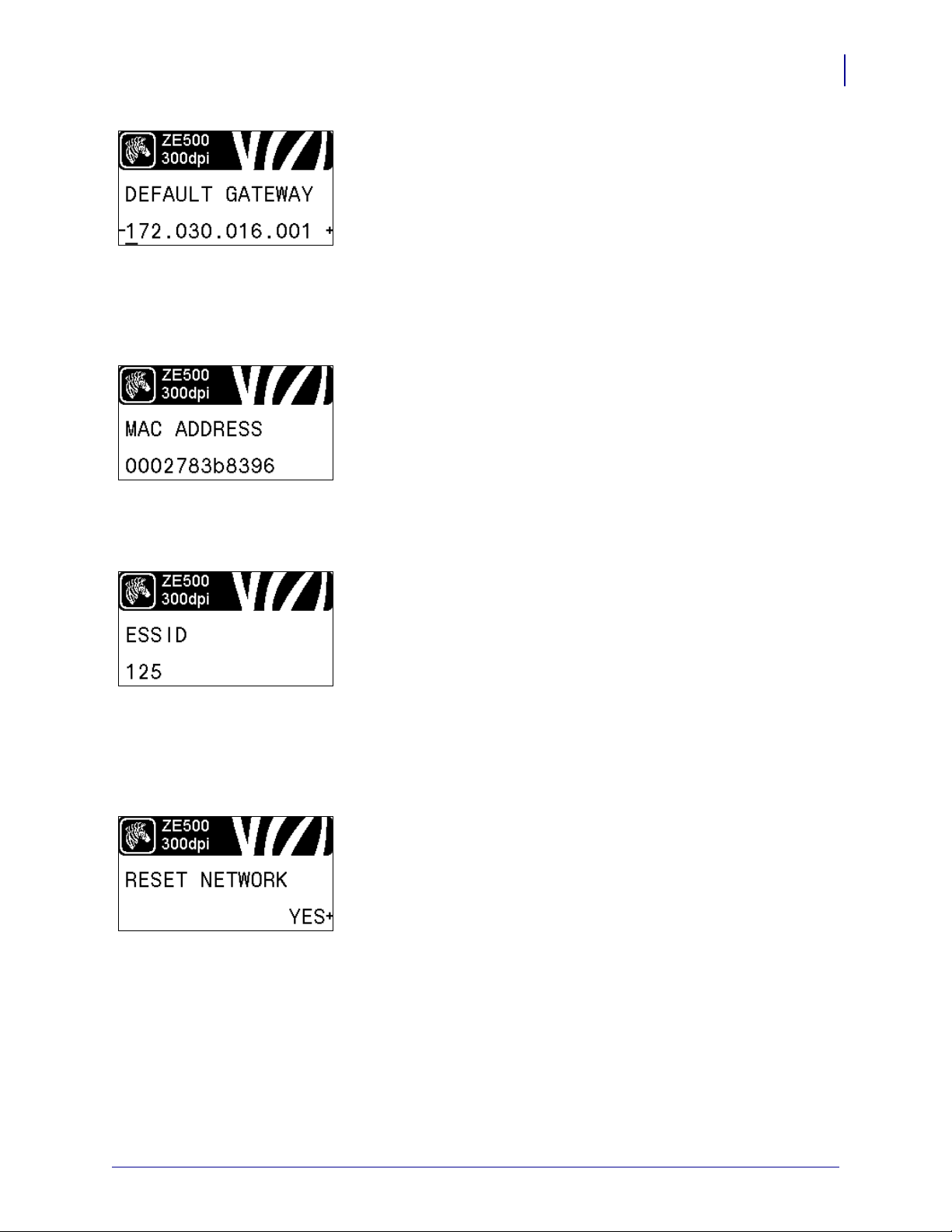
Set the Default Gateway*
View and, if necessary, change the default gateway.
Changes are saved only if IP PROT OC OL is set to PERMANENT.
To allow any saved changes to take effect, use
RESET NETWORK
on page 35 to reset the print server.
See Default Gateway on page 89 for more information.
* This menu item appears only if a wired or wireless print server
is installed in your printer.
View the MAC Address*
View the Media Acc ess Control (MAC) address of the print server
that is installed in the printer (wired or wireless).
See MAC Address on page 89 for more information.
* This menu item, which cannot be modified from the control
panel, appears only if a wired or wireless print server is
installed in your printer.
35
View the ESSID Value*
The Extended Service Set Identification (ESSID) is an identifier
for your wireless network. This setting, which cannot be modified
from the control panel, gives the ESSID for the current wireless
configuration.
See ESSID on page 90 for more information.
* This menu item, which cannot be modified from the control
panel, appears only if a wir eless print server is instal led in your
printer.
Reset the Network Settings*
This option resets the wired or wireless print server. Y ou must reset
the print server to allow any changes to the network se ttings to take
effect.
See Reset Network on page 90 for more information.
* This menu item appears only if a wired or wireless print server
is installed in your printer.
3/27/14 ZE500™ User Guide P1051584-003
Page 36

Introduction
36
Control Panel Display
Specify the Password Level
This option resets the wired or wireless print server. Y ou must reset
the print server to allow any changes to the network se ttings to take
effect.
See Password Level on page 86 for more information.
* This menu item appears only if a wired or wireless print server
is installed in your printer.
Select the Display Language
If necessary, change the language that the printer displays.
See Language on page 91 for more information.
Note • The selections for this parameter are displayed in
the actual languages to make it easier for you to find one
that you are able to read.
P1051584-003 ZE500™ User Guide 3/27/14
Page 37

Types of Media
Important • Zebra strongly recommends the use of Zebra-brand supplies for continuous
high-quality printing. A wide range of paper, polypropylene, polyester, and vinyl stock has
been specifically engineered to enhance the printing capabilities of the print engine and to
prevent premature printhead wear. To purchase supplies, go to
http://www.zebra.com/howtobuy.
Your print engine can use various types of media:
• Standard media—Most standard media uses an adhesive backing that sticks individual
labels or a continuous length of labels to a liner. Standard media can come on rolls or in a
fanfold stack (Table 2).
• Tag stock—Tags are usually made from a heavy paper. Tag stock does not have adhesive
or a liner, and it is typically perforated between tags. Tag stock can come on rolls or in a
fanfold stack (Table 2).
• Radio frequency identification (RFID) “smart” media—RFID
media can be used in a printer that is equipped with an RFID
reader/encoder. RFID la bels are made from the same materi als and
adhesives as non-RFID labels. Each label has an R FID transponde r
(sometimes called an “inlay”), made of a chip and an antenna,
embedded between the label and the liner. The shape of the transponder varies by
manufacturer and is visible through the label. All “smart” labels have memory that can be
read, and many have memory that can be encoded.
Introduction
Types of Media
37
Important • Transponder placement within a label depends on the transponder type and
the printer model. Make sure that you are using the correct “smart ” media for your pri nter.
For more information, refer to the RFID Programming Guide 2. A copy of the manual is
available at http://www.zebra.com/manuals or on the user CD that came with your print
engine. For transponder placement details, go to http://www.zebra.com/transponders.
3/27/14 ZE500™ User Guide P1051584-003
Page 38

Introduction
38
Types of Media
Table 2 • Roll and Fanfold Media
Media Type How It Looks Description
Non-Continuous
Roll Media
Roll media is wound on a 3-in. (76-mm) core. Individual
labels or tags are separated by one or more of the following
methods:
• Web media separat es labels by gaps, holes, or notches.
• Black mark media uses pre-printed black marks on the
back side of the media to indicate label separations.
Non-Continuous
Fanfold Media
Continuous
Roll Media
• Perforated media has perforations that allow the labels or
tags to be separated from each other easily. The media may
also have black marks or other separations between labels
or tags.
Fanfold media is folded in a zigzag pattern. Fanfold media can
have the same label separations as non-continuous roll media.
The separations would fall on or near the folds.
Roll media is wound on a 3-in. (76-mm) core.
Continuous roll media does not have gaps, holes, notches , o r
black marks to indicate label separations. This allows the
image to be printed anywhere on the label. Sometimes a cutter
is used to cut apart individual labels.
P1051584-003 ZE500™ User Guide 3/27/14
Page 39

Ribbon Overview
Outside Inside
Ribbon is a thin film that is coated on one side with wax, resin, or wax resin, which is
transferred to the media during the thermal transfer process. The media determines whether
you need to use ribbon and how wide the ribbon must be.
When ribbon is used, it must be as wide as or wider than the media being used. If the ribbon is
narrower than the media, areas of the printhead are unprotected and subject to premature wear.
When to Use Ribbon
Thermal Transfer media requires ribbon for printing while Direct Thermal media does not.
To determine if ribbon must be used with a particular media, perform a media scratch test.
To perform a media scratch test, complete these steps:
1. Scratch the print surface of the media rapidly with your fingernail.
2. Did a black mark appear on the media?
Introduction
Ribbon Overview
39
If a black mark... Then the media is...
Does not appear on the media Thermal transfer. A ribbon is required.
Appears on the media Direct thermal. No ribbon is required.
Coated Side of Ribbon
Ribbon can be wound with the coated side on the inside or outside (Figure 6). This print
engine can only use ribbon that is coated on the outside. If you are unsure which side of a
particular roll of ribbon is coated, perform an adhesive test or a ribbon scratch test to
determine which side is coated.
Figure 6 • Ribbon Coated on Outside or Inside
3/27/14 ZE500™ User Guide P1051584-003
Page 40

Introduction
40
Ribbon Overview
Adhesive Test
If you have labels available, perform the adhesive test to determine which side of a ribbon is
coated. This method works well for ribbon that is already installed.
To perform an adhesive test, complete these steps:
1. Peel a label from its liner.
2. Press a corner of the sticky side of the label to the outer surface of the roll of ribbon.
3. Peel the label off of the ribbon.
4. Observe the results. Did flakes or particles of ink from the ribbon adhere to the label?
If ink from the ribbon... Then...
Adhered to the label The ribbon is coated on the outside and can be
used in this printer.
Did not adhere to the label The ribbon is coated on the inside and cannot
be used in this print engine.
To verify this, repeat the test on the other
surface of the roll of ribbon.
Ribbon Scratch Test
Perform the ribbon scratch test when labels are unavailable.
To perform a ribbon scratch test, complete these steps:
1. Unroll a short length of ribbon.
2. Place the unrolled section of ribbon on a piece of paper with the outer surface of the
ribbon in contact with the paper.
3. Scratch the inner surface of the unrolled ribbon with your fingernail.
4. Lift the ribbon from the paper.
5. Observe the results. Did the ribbon leave a mark on the paper?
If the ribbon... Then...
Left a mark on the paper The ribbon is coated on the outside and can be
used in this printer.
Did not leave a mark on the
paper
The ribbon is coated on the inside and cannot
be used in this print engine.
To verify this, repeat the test on the other
surface of the roll of ribbon.
P1051584-003 ZE500™ User Guide 3/27/14
Page 41

Printer Setup and
Operation
This section assists the technician with initial setup and operation of the print engine.
2
Contents
Handling the Print Engine . . . . . . . . . . . . . . . . . . . . . . . . . . . . . . . . . . . . . . . . . . . . . . . . 42
Unpack and Inspect the Print Engine. . . . . . . . . . . . . . . . . . . . . . . . . . . . . . . . . . . . . . 42
Remove Additional Shipping Materials . . . . . . . . . . . . . . . . . . . . . . . . . . . . . . . . . . . . 42
To Store the Print Engine. . . . . . . . . . . . . . . . . . . . . . . . . . . . . . . . . . . . . . . . . . . . . . . 45
To Ship the Print Engine . . . . . . . . . . . . . . . . . . . . . . . . . . . . . . . . . . . . . . . . . . . . . . . 45
Print Engine Installation . . . . . . . . . . . . . . . . . . . . . . . . . . . . . . . . . . . . . . . . . . . . . . . . . . 46
Requirements. . . . . . . . . . . . . . . . . . . . . . . . . . . . . . . . . . . . . . . . . . . . . . . . . . . . . . . . 46
Dimensions and Clearance Needs . . . . . . . . . . . . . . . . . . . . . . . . . . . . . . . . . . . . . . . 47
Install the Print Engine in an Applicator. . . . . . . . . . . . . . . . . . . . . . . . . . . . . . . . . . . . 52
Select a Data Communication Interface. . . . . . . . . . . . . . . . . . . . . . . . . . . . . . . . . . . . . . 53
Data Cables. . . . . . . . . . . . . . . . . . . . . . . . . . . . . . . . . . . . . . . . . . . . . . . . . . . . . . . . . 56
Connect the Print Engine to a Power Source. . . . . . . . . . . . . . . . . . . . . . . . . . . . . . . . . . 57
Power Cord Specifications. . . . . . . . . . . . . . . . . . . . . . . . . . . . . . . . . . . . . . . . . . . . . . 58
Load Ribbon and Media. . . . . . . . . . . . . . . . . . . . . . . . . . . . . . . . . . . . . . . . . . . . . . . . . . 60
3/27/14 ZE500™ User Guide P1051584-003
Page 42

Printer Setup and Operation
42
Handling the Print Engine
Handling the Print Engine
This section describes how to handle your print engine.
Unpack and Inspect the Print Engine
Important • Zebra Technologies is not responsible for any damage incurred during the
shipment of the equipment and will not repair this damage under warranty.
When you receive the print engine, do the following:
1. Immediately unpack the print engine.
2. Check all exterior surfaces for damage.
3. Raise the media door, and inspect the media compartment for damage to components.
4. If you discover shipping damage during inspection, do the following:
• Immediately notify the shipping company, and file a damage report.
• Keep all packaging material for shipping company inspection.
• Notify your authorized Zeb ra reseller.
Remove Additional Shipping Materials
1. If your print engine includes the optional applicator port, complet e this step. If it does not,
continue with
Caution • The print engine ships with the following caution label over the optional
applicator port:
Applying external power when the print engine is configured for internal power will
damage your print engine.
For +5V non-isolated mode (internal power):
a. No configuration is necessary. Remove the caution sticker from the applicator
port.
b. Continue with step 2.
step 2.
For +5V to +28V isolated mode (external power):
a. The jumpers on the applicator interface board must be reconfigured. See
Applicator Interface Board Reconfiguration on page 145 for instructions.
b. Remove the caution sticker from the applicator port.
c. Continue with step 2.
P1051584-003 ZE500™ User Guide 3/27/14
Page 43

Printer Setup and Operation
1
Handling the Print Engine
2. Remove the metal spacer that ships next to the printhead-release latch. (Right-hand unit
shown.)
a. Cut the cable tie (1) that secured the printhead-release latch during shipping.
43
b. Rotate the printhead-release latch to expose the metal spacer.
3/27/14 ZE500™ User Guide P1051584-003
Page 44

Printer Setup and Operation
44
Handling the Print Engine
c. Remove the metal spacer.
d. Rotate the printhead-release latch to the closed position.
3. Cut and remove other cable ties that were used in the media compartment (if any).
P1051584-003 ZE500™ User Guide 3/27/14
Page 45

To Store the Print Engine
If you are not placing the print engine into immediate operat ion, repackage it using th e original
packing materials. You may store the print engine under the following conditions:
• Temperature: –40°F to 140°F (–40° to 60°C)
• Relative humidity: 5% to 85% non-condensing
To Ship the Print Engine
Save all packing materials in case you need to ship the print engine in the future.
To ship the print engine, do the following:
1. Turn off (O) the print engine, and disconnect all cables.
2. Remove any media, ribbon, or loose objects from the print engine interior.
3. Close the printhead.
Printer Setup and Operation
Handling the Print Engine
45
4. Carefully pack the print engine i nt o the original container or a suitable alternate container
to avoid damage during transit. A shipping container can be purchased from Zebra if the
original packaging has been lost or destroyed.
3/27/14 ZE500™ User Guide P1051584-003
Page 46

Printer Setup and Operation
46
Print Engine Installation
Print Engine Installation
This section provides basic information for mounting the print engine into an applicator. The
illustrations in this section show the print eng ine from dif ferent angles a nd include di mensions
and clearance needs.
Requirements
Stability When the print engine is mounted, the complete assembly must be physically
stable. When the print engine is loaded with ribbon and media, the equipment must not
become physically unstable.
Ventilation and Temperature Provide ventilation for the print engine mounting enclosure
to remove heat and ensure uninterrupted, trouble-free operation of the print engine. Ambient
air temperature surrounding the print engine must not exceed the following:
• Temperature: 32° to 105°F (0° to 41°C)
• Relative humidity: 20% to 95% non-cond ensing
Power Requirements Consider the current rating of the print engine during installation.
When power is applied to the print engine and th e enclosi ng equi pment, an overloa d condi tion
must not be created.
Grounding Requirements Maintain reliable g ro undi ng of the prin t en gin e. Pay particular
attention to the AC power supply connections so that earth ground is maintained through the
AC power input connector.
Clearance for Cables and Connectors Allow ample space at the rear of the print engine
for electronic connectors and dressing of the following cables: IEC power cord, serial and/or
parallel host communication cable, optional host communication cable (Ethernet), and the
discrete signal (applicator) interface cable.
Power Cord Requirements The IEC power cord does not have a strain relief on the print
engine. If the operating characteristics of the applicator include vibration or strain on the
power cord, provide an appropriate clamping mechanism to avoid unintentional disconnection
of the power cord from the print engine.
P1051584-003 ZE500™ User Guide 3/27/14
Page 47

Dimensions and Clearance Needs
This section shows measurements relevant when installing the ZE500 print engine in an
applicator.
Front View (Right-Hand Print Engine Shown)
5 mounting screws
- 0.218 in. (5.5 mm) through
- counterbore 0.350 in. x 0.197 in. (8.9 x 5 mm) deep
- socket head cap screw (M5)
Printer Setup and Operation
Print Engine Installation
47
0.669 in.
(17 mm)
18°
0.532 in
(13.50 mm)
0.721 in
(18.31 mm)
3/27/14 ZE500™ User Guide P1051584-003
0.335 in.
(8.50 mm)
Page 48

Printer Setup and Operation
48
Print Engine Installation
Rear View
9.648 in.
(245 ± 0.1 mm)
0.445 in.
(11.3 mm)
P1051584-003 ZE500™ User Guide 3/27/14
Page 49

Top View
16.62 in. (422.1 mm)
Printer Setup and Operation
Print Engine Installation
49
3/27/14 ZE500™ User Guide P1051584-003
Page 50

Printer Setup and Operation
12.13 in
(308.2 mm)
1.454 in. (37 mm)
15.89 in.
(403.7 mm)
12.73 in.
(323.2 mm)
7.34 in.
(186.5 mm)
14.95 in. (379.73 mm)
19.87 in. (504.7 mm)
0.613 in.
(15.6 mm)
0.52 in.
(13.2 mm)
Ribbon and
media edge
First print
element
Mainframe
50
Print Engine Installation
Side View—ZE500-4 Print Engine
P1051584-003 ZE500™ User Guide 3/27/14
Page 51

Side View—ZE500-6 Print Engine
0.613 in.
(15.6 mm)
0.52 in.
(13.2 mm)
Ribbon and
media edge
First print
element
Mainframe
Printer Setup and Operation
Print Engine Installation
51
3/27/14 ZE500™ User Guide P1051584-003
Page 52

Printer Setup and Operation
4
2
1
3
1
1
52
Print Engine Installation
Install the Print Engine in an Applicator
To install the print engine into an applicator, complete these steps:
This section provides the basic instructions for installing the print engine into an applicator.
Caution • If the print engine is installed improperly, it could fall out of the applicator and
cause injury. The center mounting bolt and four mounting screws must be installed and
secured. See
1. See Figure 7. Install the center mounting bolt into the center hole on the applicator.
2. Carefully place the keyhole on the center mounting bolt.
Note • The keyhole and the center mounting bolt are designed to support the print engine
Figure 7 for the location of the bolt and screws.
and assist in installing and removing the four mounting screws.
3. Install the four corner mounting screws to secure the print engine to the applicator.
Figure 7 • Front View of Print Engine in Applicator
Mounting screws (four total)
1
P1051584-003 ZE500™ User Guide 3/27/14
Keyhole
2
Center mounting bolt (shown inside hole on applicator)
3
Applicator
4
Page 53

Select a Data Communication Interface
1
You may connect your print engine to a computer using one or more of the available
connections. The standard conn ections are shown in
print server option or a parallel port may also be present on your print engine.
Figure 8 • Communication Interfaces
Printer Setup and Operation
Select a Data Communication Interface
Figure 8. A ZebraNet wired or wireless
53
parallel port
USB port
wired Ethernet port
serial port
applicator port
1
Table 3 on page 54 provides basic information about data communication interfaces that you
can use to connect your print engine to a computer. You may send label formats to the print
engine through any data communication interface that is available. Select an interface that is
supported by both your print engine and your computer or your Local Area Network (LAN).
3/27/14 ZE500™ User Guide P1051584-003
Page 54

Printer Setup and Operation
54
Select a Data Communication Interface
Caution • Ensure that the print engine power is off (O) before connecting data
communications cables. Connecting a data communications cable while the power is on (
may damage the print engine.
I)
Table 3 • Data Communication Interfaces
Interface
Standard or
Option
Description
RS-232 Serial Standard Limitations and Requirements
• Maximum cable length of 50 ft (15.24 m).
• You may need to change print engine parameters to match the
host computer.
• You need to use a null-modem adaptor to connect to the print
engine if using a standard modem cable.
Connections and Configuration The baud rate, number of
data and stop bits, the parity, and the XON/XOFF or DTR control
must match those of the host computer.
USB Standard Limitations and Requirements
• Maximum cable length of 16.4 ft (5 m).
• No print engine parameter changes required to match the host
computer.
Connections and Configuration No additional
configuration is necessary.
8-bit Parallel data
interface
Standard Limitations and Requirements
• Maximum cable length of 10 ft (3 m).
• Recommended cable length of 6 ft (1.83 m).
• No print engine parameter changes required to match the host
computer.
• A wired or wireless print server (if installed) takes up this port
on the print engine.
Connections and Configuration No additional
configuration is necessary.
P1051584-003 ZE500™ User Guide 3/27/14
Page 55

Printer Setup and Operation
Select a Data Communication Interface
Table 3 • Data Communication Interfaces (Continued)
55
Interface
Standard or
Option
Description
Applicator Option Limitations and Requirements The applicator interface is
used to control the print engine fro m a n ext erna l device (usuall y a
label applicator).
Connections and Configuration The print engine ships with
the following caution label over the optional applicator port:
• For +5V non-isolated mode (internal pow er), no configuration
is necessary.
• For +5V to +28V isolated mode (external power), the jumpers
on the applicator interface board must be reconfigured. See
Applicator Interface Board Reconfiguration on page 145.
Caution • Do not apply external power until after the
applicator interface board is reconfigured for isolated mode.
Applying external power when the print engine is configured
for internal power will damage your print engine.
Wired Ethernet print
server
Option Limitations and Requirements
• Can print to the print engine from any computer on your LAN.
• Can communicate with the printer through the print engine’s
web pages.
• The printer must be configured to use your LAN.
• A parallel connection or a wireless print server (if installed)
takes up this port on the print engine.
Caution • Be careful not to plug a USB cable into a wired
Ethernet print server connector on the print engine because
doing so will damage the Ethernet connector.
Connections and Configuration Refer to the ZebraNet
Wired and Wireless Print Servers User Guide for configuration
instructions. A copy of this manual is ava ilable at
http://www.zebra.com/manuals or on the user CD that came with
your print engine.
Note • To use this connection, you may need to remove a
factory-installed plug that is designed to keep someone
from accidentally plugging a USB connector into this port.
3/27/14 ZE500™ User Guide P1051584-003
Page 56

Printer Setup and Operation
56
Select a Data Communication Interface
Table 3 • Data Communication Interfaces (Continued)
Interface
Standard or
Option
Description
Wireless print server Option Limitations and Requirements
• Can print to the print engine from any computer on your
Wireless Local Area Network (WLAN).
• Can communicate with the printer through the print engine’s
web pages.
• The print engine must be configured to use your WLAN.
• A parallel connection or a wired print server (if install ed) takes
up this port on the print engine.
Configuration Refer to the ZebraNet Wired and Wireless Print
Servers User Guide for configuration instructions. A copy of this
manual is available at
http://www.zebra.com/manuals or on the
user CD that came with your print engine.
Data Cables
You must supply all data cables for your application.
Ethernet cables do not require shielding, but all other data cables must be fully shielded and
fitted with metal or metallized connector shel ls. Unshie lde d data cables may increase ra dia ted
emissions above the regulated limits.
To minimize electrical noise pickup in the cable:
• Keep data cables as short as possible.
• Do not bundle the data cables tightly with the power cords.
• Do not tie the data cables to power wire conduits.
P1051584-003 ZE500™ User Guide 3/27/14
Page 57

Connect the Print Engine to a Power Source
115 V AC
230 V AC
Connect the Print Engine to a Power Source
The AC power cord must have a three-prong female connector on one end that plugs into the
mating AC power connector at the rear of the print engine. If a power cable was not included
with your print engine, refer to
Caution • For personnel and equipment safety, always use an approved three-conductor
power cord specific to the region or country intended for installation. This cord must use an
IEC 320 female connector and the appropriate region-specific three-conductor grounded
plug configuration.
To connect the print engine to a power source, complete these steps:
1. Plug the female end of the A/C power cord into the A/C power connector on the back of
the print engine.
Power Cord Specifications on page 58.
Printer Setup and Operation
57
2. Plug the male end of the A/C power cord into an appropriate power outlet.
3/27/14 ZE500™ User Guide P1051584-003
Page 58

Printer Setup and Operation
58
Connect the Print Engine to a Power Source
3. Turn on (I) the print engine.
The print engine boots up and performs a self-test.
Power Cord Specifications
Caution • For personnel and equipment safety, always use an approved three-conductor
power cord specific to the region or country intended for installation. This cord must use an
IEC 320 female connector and the appropriate region-specific, three-conductor grounded
plug configuration.
Depending on how your print engine was ordered, a power cord may or may not be included.
If one is not included or if the one included is not suitable for your requirements, see
and refer to the following guidelines:
• The overall cord length must be less than 9.8 ft. (3 m).
• The cord must be rated for a minimum of 10 A, 250 V.
• The chassis ground (earth) must be connected t o ensure safety and re duce electromagnetic
interference.
Figure 9
P1051584-003 ZE500™ User Guide 3/27/14
Page 59

Printer Setup and Operation
3
1
2
4
Connect the Print Engine to a Power Source
Figure 9 • Power Cord Specifications
59
AC power plug for your country—This should bear the certification
1
mark of at least one of the known international safety organizations
Figure 10).
(
3-conductor HAR cable or other cable approved for your country.
2
IEC 320 connector—This should bear the certification mark of at
3
least one of the known international safety organizations (
Length ≤ 9.8 ft. (3 m). Rating 10 Amp minimum, 250 VAC.
4
Figure 10).
Figure 10 • International Safety Organization Certification Symbols
3/27/14 ZE500™ User Guide P1051584-003
Page 60

Printer Setup and Operation
LH RH
60
Load Ribbon and Media
Load Ribbon and Media
Use the instructions in this section to load ribbon (if used) and media in a ZE500™ print
engine. Ribbon is used with thermal transfer labels. For direct thermal labels, do not load
ribbon in the print engine. To
When to Use Ribbon on page 39.
Caution • While performing any tasks near an open printhead, remove all rings, watches,
hanging necklaces, identification badges, or other metallic objects that could touch the
printhead. You are not required to turn off the printer power when working near an open
printhead, but Zebra recommends it as a precaution. If you turn off the power, you will lose
all temporary settings, such as label formats, and you must reload them before you resume
printing.
Important • Use ribbon that is wider than the media to protect the printhead from wear.
Ribbon must be coated on the outside. See
information.
To load ribbon and media, complete these steps:
determine if ribbon must be used with a particular media, see
Coated Side of Ribbon on page 39 for more
Loading Ribbon
1.
Caution • The printhead may be hot and could cause severe burns. Allow the
printhead to cool.
Rotate the printhead-release latch to the open position.
P1051584-003 ZE500™ User Guide 3/27/14
Page 61

Printer Setup and Operation
LH RH
LH RH
LH RH
Load Ribbon and Media
2. Position the ribbon roll with the loose end unrolling in the direction shown.
3. Place the roll of ribbon on the ribbon supply spindle. Push the roll back as far as it will go.
61
4. Place an empty ribbon core on the ribbon take-up spindle. Push the core back as far as it
will go.
3/27/14 ZE500™ User Guide P1051584-003
Page 62

Printer Setup and Operation
2
3
1
LH RH
2
3
1
RHLH
62
Load Ribbon and Media
5.
Caution • The printhead may be hot and could cause severe burns. Allow the
printhead to cool.
Thread the ribbon under the lower ribbon guide roller (1), under the printhead
assembly
(2), and then over the upper ribbon guide roller (3).
6. Wind the ribbon around the core on the ribbon take-up spindle.
P1051584-003 ZE500™ User Guide 3/27/14
Page 63

Printer Setup and Operation
LH RH
LH RH
Load Ribbon and Media
Loading Media
7. Load media on the media supply reel of the applicator (refer to the applicator’s
documentation for more information).
8. Press the release button on the pinch roller assembly. Allow the assembly to pivot upward.
63
9. Slide the media guide all the way out.
3/27/14 ZE500™ User Guide P1051584-003
Page 64

Printer Setup and Operation
LH RH
1
2
3
12
3
RH
LH
64
Load Ribbon and Media
10. Thread the media under the upper guide post (1), below th e pinch roller assembly (2), and
under the printhead assembly
11. Extend approximately 30 in. (75 cm) of media past the peel bar. Remove and discard the
(3).
labels from the liner on this exposed media.
P1051584-003 ZE500™ User Guide 3/27/14
Page 65

Printer Setup and Operation
LH RH
LH RH
LH RH
12. Slide in the media guide until it just touches the edge of the media.
13. Press down on the pinch roller assembly until it locks closed.
Load Ribbon and Media
65
14. Rotate the printhead-release latch to the closed position.
3/27/14 ZE500™ User Guide P1051584-003
Page 66

Printer Setup and Operation
LH RH
LH RH
66
Load Ribbon and Media
15. Raise the peel roller latch so that the peel roller assembly pivots downward.
16. Thread the liner around the peel bar, under the platen roller, and through the peel roller
assembly.
Important • If the applicator has an air tube, route the liner between the air tube and the
peel bar. Do not thread the liner over the air tube.
P1051584-003 ZE500™ User Guide 3/27/14
Page 67

Printer Setup and Operation
LH RH
Load Ribbon and Media
17. Rotate the peel roller assembly up until it locks into the closed position.
18. Thread the liner around the take-up spindle of the applicator (refer to the applicator’s
documentation for more information).
19. Close the media door.
67
20. If desired, perform the CANCEL Self T e st on page 149 to verify that your printer is able to
print.
3/27/14 ZE500™ User Guide P1051584-003
Page 68

Printer Setup and Operation
Notes • ___________________________________________________________________
__________________________________________________________________________
__________________________________________________________________________
__________________________________________________________________________
__________________________________________________________________________
__________________________________________________________________________
__________________________________________________________________________
__________________________________________________________________________
__________________________________________________________________________
__________________________________________________________________________
68
Load Ribbon and Media
P1051584-003 ZE500™ User Guide 3/27/14
Page 69

3
Printer Configuration
and
This section assists you with configuration of and adjustments to the print engine.
Contents
Changing Printer Settings . . . . . . . . . . . . . . . . . . . . . . . . . . . . . . . . . . . . . . . . . . . . . . . . 70
Print Settings . . . . . . . . . . . . . . . . . . . . . . . . . . . . . . . . . . . . . . . . . . . . . . . . . . . . . . . . 71
Maintenance and Diagnostic Tools . . . . . . . . . . . . . . . . . . . . . . . . . . . . . . . . . . . . . . . 80
Network Settings . . . . . . . . . . . . . . . . . . . . . . . . . . . . . . . . . . . . . . . . . . . . . . . . . . . . . 87
Language Settings. . . . . . . . . . . . . . . . . . . . . . . . . . . . . . . . . . . . . . . . . . . . . . . . . . . . 91
Sensor Settings . . . . . . . . . . . . . . . . . . . . . . . . . . . . . . . . . . . . . . . . . . . . . . . . . . . . . . 93
Port Settings . . . . . . . . . . . . . . . . . . . . . . . . . . . . . . . . . . . . . . . . . . . . . . . . . . . . . . . . 94
Calibrate the Ribbon and Media Sensors . . . . . . . . . . . . . . . . . . . . . . . . . . . . . . . . . . . . 97
Remove Used Ribbon . . . . . . . . . . . . . . . . . . . . . . . . . . . . . . . . . . . . . . . . . . . . . . . . . . 101
Adjust the Sensors. . . . . . . . . . . . . . . . . . . . . . . . . . . . . . . . . . . . . . . . . . . . . . . . . . . . . 102
Transmissive Media Sensor. . . . . . . . . . . . . . . . . . . . . . . . . . . . . . . . . . . . . . . . . . . . 102
Reflective Media Sensor . . . . . . . . . . . . . . . . . . . . . . . . . . . . . . . . . . . . . . . . . . . . . . 103
Ribbon Sensor. . . . . . . . . . . . . . . . . . . . . . . . . . . . . . . . . . . . . . . . . . . . . . . . . . . . . . 103
Toggle Positioning . . . . . . . . . . . . . . . . . . . . . . . . . . . . . . . . . . . . . . . . . . . . . . . . . . . . . 104
Printhead Pressure Adjustment . . . . . . . . . . . . . . . . . . . . . . . . . . . . . . . . . . . . . . . . . . . 106
Adjustment
3/27/14 ZE500™ User Guide P1051584-003
Page 70

Printer Configuration and Adjustment
70
Changing Printer Settings
Changing Printer Settings
This section presents the printe r settings that you can change and identifies the tools for
changing them. These tools include the following:
• ZPL and Set/Get/Do (SGD) commands (See the Zebra® Programming Guide for more
information.)
• The printer’s control panel display (See Contr o l Panel Display on page 15 for more
information.)
• The printer’s web pages when the printer has an active wired or wireless print server
connection (See the ZebraNet Wired and Wireless Print Servers User Guide for more
information.)
This section contains the following subsections:
• Print Settings on page 71
• Maintenance and Diagnostic Tools on page 80
• Network Settings on page 87
• Language Settings on page 91
• Port Settings on page 94
For information about RFID parameters, see the RFID Programming Guide 2.
Note • You can download the latest copy of the referenced manuals from
http://www.zebra.com/manuals.
P1051584-003 ZE500™ User Guide 3/27/14
Page 71

Print Settings
Table 4 • Print Settings
Printer Configuration and Adjustment
Changing Printer Settings
71
Print
Darkness
Set the darkness to the lowest setting that provid es good print quality. If you set the darkness
too high, the label image may print unclearly, bar codes may not scan correctly, the ribbon
may burn through, or the printhead may wear prematurely.
If desired, use the FEED Self Test on page 134 to determine the best darkness setting.
Accepted values:
Related ZPL command(s):
SGD command used:
0.0 – 30.0
^MD, ~SD
print.tone
Control panel menu item: DARKNESS on page 19
Printer web page:
View and Modify Printer Settings > General Setup >
Darkness
Print Speed Select the speed for printing a label (given in inches per second). Slower print speeds
typically yield better print quality.
Accepted values:
Related ZPL command(s):
SGD command used:
• ZE500-4 203 dpi: 2–12 ips
• ZE500-4 300 dpi: 2–12 ips
• ZE500-6 203 dpi: 2–12 ips
• ZE500-6 300 dpi: 2–10 ips
^PR
media.speed
Control panel menu item: PRINT SPEED on page 19
Printer web page:
View and Modify Printer Settings > General Setup >
Print Speed
Slew Speed The slew speed is the speed at which the printer skips over the areas in a label format that
are blank across the full width of the image. A faster slew speed may redu ce prin tin g time.
The print engine automatically senses when to apply this higher speed.
Accepted values:
Related ZPL command(s):
SGD command used:
• ZE500-4 203 dpi: 2–12 ips
• ZE500-4 300 dpi: 2–12 ips
• ZE500-6 203 dpi: 2–12 ips
• ZE500-6 300 dpi: 2–10 ips
^PR
none
Control panel menu item: SLEW SPEED on page 19
Printer web page:
none
3/27/14 ZE500™ User Guide P1051584-003
Page 72
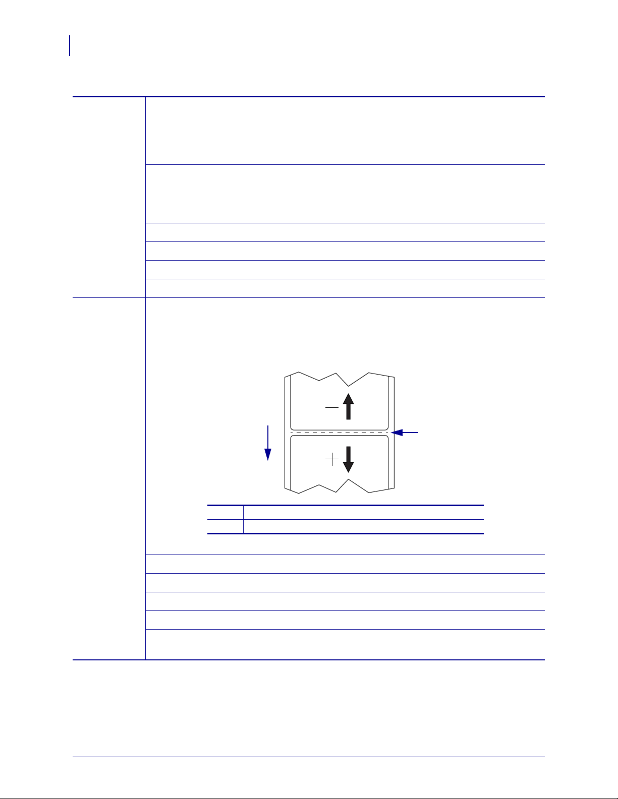
Printer Configuration and Adjustment
1
2
1
Media direction
2
Factory-set tear line location at position 000
72
Changing Printer Settings
Table 4 • Print Settings (Continued)
Backfeed
Speed
Tear-Off
Position
Backfeed refers to the backward motion of the media from the tear -off or pe el-off positio n to
the print position. This motion occurs so that more of the lead edge of each l abel can be used
for printing. Reducing backfeed speed can mitigate some issues. In general, reducing the
backfeed speed may improve print quality at the start of the label. This speed defaults to
ips.
2
Accepted values:
Related ZPL command(s):
SGD command used:
• ZE500-4 203 dpi: 2–12 ips
• ZE500-4 300 dpi: 2–12 ips
• ZE500-6 203 dpi: 2–12 ips
• ZE500-6 300 dpi: 2–10 ips
^PR
none
Control panel menu item: BACKFEED SPEED on page 19
Printer web page:
none
If necessary, adjust the position of the media over the tear-off bar after printing.
• Higher numbers move the media out (the tear line moves closer to the leading edge of
the next label).
• Lower numbers move the media in (the tear line moves closer to the edge of the label
just printed).
Accepted values:
Related ZPL command(s):
SGD command used:
–120 to 120
~TA
none
Control panel menu item: TEAR OFF on page 20
Printer web page:
P1051584-003 ZE500™ User Guide 3/27/14
View and Modify Printer Settings > General Setup >
Tear
Off
Page 73

Printer Configuration and Adjustment
Table 4 • Print Settings (Continued)
Print Mode Select a print mode that is compatible with your print engine options.
Changing Printer Settings
73
Accepted values:
• APPLICATOR—The print engine prints a label when
it receives a signal from the applicator.
• TEAR OFF—The print engine prints label formats as
it receives them. The print engine operator can tear of f
the printed labels any time after they print.
• STREAM—The print engine prints a batch of labels
with backfeed occurring only at the start and end of
the batch instead of between individual labels. This
setting increases label throughput in batch printing.
• REWIND—The print engine prints without pausing
between labels. The media is wound onto a core after
printing.
• RFID—The print engine does not backfeed between
labels. When the last label prints, the print engine
waits 1 second for another label format before feedin g
the last printed label to the tear-off position. Use this
mode when printing multiple RFID labels in Tear-Off
mode to improve throughput time.
Related ZPL command(s):
SGD command used:
^MM
media.printmode
Control panel menu item: PRINT MODE on page 20
Printer web page:
View and Modify Printer Settings > General Setup >
Print
Mode
Applicator
Port
Select the appropriate action for the applicator port, as suggested by the applicator
manufacturer.
Accepted values:
• OFF: The applicator port is off.
• MODE 1: Asserts the ~END_PRINT signal low while
the print engine is moving the label forward.
• MODE 2: Asserts the ~END_PRINT signal high
while the print engine is moving the label forward.
• MODE 3: Asserts the ~END_PRINT signal low for
milliseconds when a label has been completed and
20
positioned. Not asserted during continuous printing
modes.
• MODE 4: Asserts the ~END_PRINT signal high for
20 milliseconds when a label has been completed and
positioned. Not asserted during continuous printing
modes.
Related ZPL command(s):
SGD command used:
^JJ
device.applicator.end_print
Control panel menu item: APPLICATOR PORT on page 20
Printer web page:
View and Modify Printer Settings > Advanced Setup >
Applicator
3/27/14 ZE500™ User Guide P1051584-003
Page 74

Printer Configuration and Adjustment
74
Changing Printer Settings
Table 4 • Print Settings (Continued)
Start Print
Signal
This parameter determines how the print engine reacts to the Start Print Signal input on
3 of the applicator interface connector at the rear of the print engine.
pin
Important • The Start Print Signal is determined by the applicator manufacturer.
The print engine must use the correct setting for it to work properly.
Accepted values:
• PULSE MODE—Labels print when the signal
transitions from HIGH to LOW or LOW to HIGH, as
specified by the SGD command
device.applicator.start_print.
• LEVEL MODE—Labels print as long as the signal is
asserted LOW.
Related ZPL command(s):
SGD command used:
^JJ
none
Control panel menu item: START PRINT SIG on page 20
Printer web page:
View and Modify Printer Settings > Advanced Setup >
Start Print Sig
Media Type Select the type of media that you are using.
• If you select CONTINUOUS, you must include a label length in your label format (^LL
if you are using ZPL).
• If you select NON-CONTINUOUS for various non-continuous media, the print engine
feeds media to calculate the label length.
See Types of Media on page 47 for more information.
Accepted values:
Related ZPL command(s):
SGD command used:
• CONTINUOUS
• NON-CONTINUOUS
^MN
none
Control panel menu item: MEDIA TYPE on page 20
Printer web page:
View and Modify Printer Settings > Media Setup >
Media
Type
Print Method Specify if ribbon is being used. Thermal Transfer media requires ribbon for printing while
Direct Thermal media does not.
To determine if you need to use ribbon, see When to Use Ribbon on page 39.
Accepted values:
Related ZPL command(s):
SGD command used:
• THERMAL TRANS
• DIRECT THERMAL
^MT
none
Control panel menu item: PRINT METHOD on page 21
Printer web page:
View and Modify Printer Settings > Media Setup >
Print
Method
P1051584-003 ZE500™ User Guide 3/27/14
Page 75

Table 4 • Print Settings (Continued)
Print Width Specify the width of the labels being used.
Note • Setting the width too narrow can result in portions of a label format not being
printed on the media. Setting the width too wide waste s formatti ng memory and can
cause the printer to print off of the label and onto the platen roller. This setting can
affect the horizontal position of the label format if the image was inverted using the
^POI ZPL
II command.
Printer Configuration and Adjustment
Changing Printer Settings
75
Accepted values:
minimum: 2 dots
maximum:
• ZE500-4 203 dpi: 832 dots
• ZE500-4 300 dpi: 1228 dots
• ZE500-6 203 dpi: 1344 dots
• ZE500-6 300 dpi: 1984 dots
Related ZPL command(s):
SGD command used:
^PW
none
Control panel menu item: PRINT WIDTH on page 21
Printer web page:
View and Modify Printer Settings > Media Setup >
Print
Width
3/27/14 ZE500™ User Guide P1051584-003
Page 76

Printer Configuration and Adjustment
2
1
Label length (including interlabel gap)
2
Interlabel gap
3
Set the maximum label length to approximately
this value
1
3
76
Changing Printer Settings
Table 4 • Print Settings (Continued)
Maximum
Label Length
Set the maximum label length to a value that is at least 1.0 in. (25.4 mm) greater than the
actual label length plus the inte rl ab el gap . If you set the value to one that is smaller t ha n the
label length, the print engine assumes that continuous media is loaded, and the print engine
cannot calibrate.
For example, if the label length is 6.0 inches (152 mm) including the interlabel gap, set the
parameter for at least 7.0
inches (178 mm).
Related ZPL command(s): ^ML
Control panel menu item:
P1051584-003 ZE500™ User Guide 3/27/14
Accepted values:
SGD command used:
Printer web page:
0 to the maximum label length supported by the printer
none
MAXIMUM LENGTH on page 21
View and Modify Printer Settings > Media Setup >
Maximum
Length
Page 77

Printer Configuration and Adjustment
Table 5 • Ribbon Tension Settings
Ribbon Width
Ribbon Length
300 Meters 450 Meters 600 Meters
3 to 5 in.
(76 to 127 mm)
LOW LOW LOW
4 to 6 in.
(102 to 152 mm)
LOW LOW or MEDIUM LOW or MEDIUM
5 to 7 in.
(127 to 178 mm)
LOW or MEDIUM MEDIUM MEDIUM or HIGH
Table 4 • Print Settings (Continued)
Changing Printer Settings
77
Ribbon
Tension
Select the ribbon tension setting that is appropriate for the width or type of media being
printed. HIGH can be used for most media. The correct setting is determined by a
combination of the ribbon width and the ribbon length (
Table 5). If necessary, use a lower
value for narrow media or for glossy media.
Accepted values:
• HIGH
• MEDIUM
• LOW
Related ZPL command(s): ^JW
Backfeed
Sequence
SGD command used:
Control panel menu item: RIBBON TENSION on page 29
Printer web page:
This parameter sets when label backfeed occurs after a label is removed in some print
modes. It has no effect in Rewind mode. This setting is superseded by
as part of a label format.
Accepted values:
Related ZPL command(s): ~JS
SGD command used:
Control panel menu item: BACKFEED on page 30
Printer web page:
none
none
~JS when received
• AFTER (backfeed occurs immediately after the last
label is completed)
• OFF (no backfeed)
• BEFORE (backfeed occurs before the forward motion
of the first label)
• DEFAULT
none
View and Modify Printer Settings > Advanced Setup >
Backfeed
3/27/14 ZE500™ User Guide P1051584-003
Page 78

Printer Configuration and Adjustment
78
Changing Printer Settings
Table 4 • Print Settings (Continued)
Label Top
Position
Label Left
Position
This parameter adjusts the print positio n vertically on the label. Positive n umb ers ad ju st the
label top position farther down the lab el (a way from t he prin th ead ) by t he spec ified n umber
of dots. Negative numbers adjust the position up the label (toward the printhead).
Accepted values:
–120 to 120
Related ZPL command(s): ^LT
SGD command used:
none
Control panel menu item: LABEL TOP on page 30
Printer web page:
View and Modify Printer Settings > General Setup >
Label Top
If necessary , shift the print position horizontally on t he label. Positive numbe rs move the left
edge of the image toward the center of the label by the number of dots selected, while
negative numbers move the left edge of the image toward the left edge of the label.
Accepted values:
–9999 to 9999
Related ZPL command(s): ^LS
SGD command used:
none
Control panel menu item: LEFT POSITION on page 30
Printer web page:
View and Modify Printer Settings > Advanced Setup >
Left Position
Head Test
Count
Error on
Pause
The ZE500-6 print engine periodically performs a test of the printhead functionality. This
parameter establishes how many labels are printed between these internal tests.
Accepted values:
0000 (disables the test) to 9999
Related ZPL command(s): ^JT
SGD command used:
none
Control panel menu item: HEAD TEST COUNT on page 30
Printer web page:
View and Modify Printer Settings > Advanced Setup >
Head Test Count
When this option is enabled and the print engine is paused, the print engine sets the
applicator error state.
Accepted values:
• ENABLED
• DISABLED
Related ZPL command(s): ^JJ
SGD command used:
none
Control panel menu item: ERROR ON PAUSE on page 31
Printer web page:
View and Modify Printer Settings > Advanced Setup >
Error on Pause
P1051584-003 ZE500™ User Guide 3/27/14
Page 79

Printer Configuration and Adjustment
Table 4 • Print Settings (Continued)
Changing Printer Settings
79
Ribbon Low
Mode
Ribbon Low
Output
The Ribbon Low feature determines if the print engine will generate a warning when the
amount of ribbon left on the roll gets low.
When the Ribbon Low feature is off, the output signal (Pin 9) does not function, the LOW
RIBBON
warning is not displayed, and the print engine co ntinues to prin t until it runs o ut of
ribbon.
When the Ribbon Low feature is enabled, output signal (Pin 9) on the applicator port is
functional. When the amount of ribbon on the supply spindle gets low, the output signal
asserts to provide a
RIBBON LOW warning. Set the output signal to assert HIGH or LOW.
Accepted values:
• ENABLED
• DISABLED
Related ZPL command(s): ^JJ
SGD command used:
none
Control panel menu item: RIBBON LOW MODE on page 31
Printer web page:
none
When the Ribbon Low feature is enabled, this parameter determines if the output signal on
Pin 9 is HIGH or LOW.
Accepted values:
Related ZPL command(s):
• ACTIVE HIGH
• ACTIVE LOW
none
Reprint
Mode
SGD command used:
device.applicator.ribbon_low
Control panel menu item: RIBBON LOW OUTPUT on page 31
Printer web page:
none
When reprint mode is enabled, you can reprint the last label printed by pressin g and holdin g
PAUSE + CANCEL on the printer’s control panel.
Accepted values:
• ON
• OFF
Related ZPL command(s): ^JZ
SGD command used:
none
Control panel menu item: REPRINT MODE on page 32
Printer web page: N/A
3/27/14 ZE500™ User Guide P1051584-003
Page 80

Printer Configuration and Adjustment
80
Changing Printer Settings
Maintenance and Diagnostic Tools
Table 6 • Maintenance and Diagnostic Tools
Early Warning
for Media and
Ribbon
Early Warning
for Maintenance
Printhead
Cleaning Interval
When this feature is enabled, the print engine provides warnings when the media or
ribbon is reaching near the end of the roll.
Accepted values:
Related ZPL command(s):
SGD command used:
MEDIA DISABLED, MEDIA ENABLED
^JH
none
Control panel menu item: EARLY WARNING MEDIA on page 21
Printer web page:
View and Modify Printer Settings > General Setup
> Early Warning (Media)
When this feature is enabled, the print engine provides warnings when the printhead
needs to be cleaned.
Accepted values:
Related ZPL command(s):
SGD command used:
MAINT. OFF, MAINT. ON
^JH
none
Control panel menu item: EARLY WARNING MAINTENANCE on page 23
Printer web page:
View and Modify Printer Settings > General Setup
> Early Warning (Maintenance)
When Early Warning for Maintenance is enabled, set this value to the length of the
media or ribbon roll that you are using.
When the printhead reaches the set length, WARNING CLEAN PRINTHEAD appears on
the control panel display. If the alert function is enabled, the print engine generates an
alert.
Accepted values:
Related ZPL command(s):
SGD command used:
0 M/0 FT to 450M/1476 FT in 50 M increments
^JH
none
Control panel menu item: HEAD CLEANING on page 23
View and Modify Printer Settings > General Setup
> Head Cleaning
Printhead Life
Expectancy
Printer web page:
When Early Warning for Maintenance is enabled, set this value to the number of inches
of media that the printhead is expected to print.
When the printhead reaches the set length, W ARNING REPLACE HEAD appears on the
control panel display. If the alert function is enabled, the print engine generates an alert.
Accepted values:
Related ZPL command(s):
SGD command used:
0 M/0 FT to 450M/1476 FT in 50 M increments
^JH
none
Control panel menu item: HEAD LIFE on page 23
Printer web page:
P1051584-003 ZE500™ User Guide 3/27/14
View and Modify Printer Settings > General Setup
> Head Life
Page 81

Printer Configuration and Adjustment
Changing Printer Settings
Table 6 • Maintenance and Diagnostic Tools (Continued)
81
Non-Resettable
Counter
User-Controlled
Counters
Print Counter
Readings
The non-resettable counter gives the total length of media that the printer has printed.
You can use firmware commands to change the unit of measure for this counter.
Related ZPL command(s):
SGD command used:
^MA (for changing unit of measure)
none
Control panel menu item: NONRESET CNTR on page 24
Printer web page:
none
Two user-controlled counters give the tot al len gt h of media that the printe r has prin ted
since the last time the counter was reset. You can use firmware commands to change the
unit of measure and reset the counters.
Related ZPL command(s):
^MA (for changing unit of measure)
~RO (for resetting counters)
SGD command used:
odometer.media_marker_count1
odometer.media_marker_count2
Control panel menu item: RESET CNTR1 on page 24
RESET CNTR2 on page 24
Printer web page:
none
Prints a label that lists the odometer readings for the following:
• the non-resettable counter
• the two user-controlled counters
• the Early Warning for Maintenance counters, which indicate when the printhead
was last cleaned and the printhead life (If the Early Warning for Maintenance
feature is disabled, the counters related to it do not print.)
Related ZPL command(s):
SGD command used:
Control panel menu item:
Printer web page:
~HQ
none
PRINT METERS on page 24
none
3/27/14 ZE500™ User Guide P1051584-003
Page 82

Printer Configuration and Adjustment
82
Changing Printer Settings
Table 6 • Maintenance and Diagnostic Tools (Continued)
Print
Information
Print the specified information on one or more labels.
• FONTS—Prints the available fonts in the print engine, including standard print
engine fonts plus any optional fonts. Fonts may be stored in RAM or Flash memory.
• BAR CODES—Prints the available bar codes in the print engine. B ar cod es may b e
stored in RAM or Flash memory.
• IMAGES—Prints the available images stored in the print engine’s RAM, Flash
memory, or optional memory card.
• FORMATS—Prints the available formats stored in the printer’s RAM, Flash
memory, or optional memory card.
• SETUP—Prints the printer configuration label.
• NETWORK—Prints the settings for any print server that is installed.
• ALL—Prints the previous six labels.
Related ZPL command(s):
Printer configuration: ~WC
Network: ~WL
Others: ^WD
SGD command used: none
Control panel menu item:
LIST FONTS on page 24
LIST BAR CODES on page 25
LIST IMAGES on page 25
LIST FORMATS on page 25
LIST SETUP on page 25
LIST NETWORK on page 25
LIST ALL on page 26
Print a Sensor
Profile
Initialize Flash
Memory
Printer web page:
View and Modify Printer Settings >
Print
Listings on Label
Shows the sensor settings compared to actual sensor readings.
To interpret the results of the sensor profile, see Sensor Profile on page 139.
Related ZPL command(s):
~JG
SGD command used: none
Control panel menu item:
Printer web page:
SENSOR PROFILE on page 26
View and Modify Printer Settings >
Print
Listings on Label
This option erases all previously stored information from Flash memory.
Caution • This option completely erases the Flash memory.
Related ZPL command(s):
^JB
SGD command used: none
Control panel menu item:
Printer web page:
INIT FLASH MEM. on page 26
View and Modify Printer Settings > Advanced
Setup > Format Memory
P1051584-003 ZE500™ User Guide 3/27/14
Page 83

Table 6 • Maintenance and Diagnostic Tools (Continued)
Power-Up Action Set the Power-Up Action
Set the action for the printer to take during the power-up sequence.
• CALIBRATE adjusts sensor levels and thresholds, determines the lab el length, an d
feeds the media to the next web.
• FEED—feeds the labels to the first registration point.
• LENGTH determines the label length using current sensor values, and feeds the
media to the next web.
• NO MOTION tells the printer not to move the media. You must manually ensure
that the web is positioned correctly, or press feed to position the next web.
• SHORT CAL sets the media and web thresholds without adjusting sensor gain,
determines the label length, and fee ds the media to the next web.
Printer Configuration and Adjustment
Changing Printer Settings
83
Head-Close
Action
Accepted values:
Related ZPL command(s):
SGD command used:
• CALIBRATE
• FEED
• LENGTH
• NO MOTION
• SHORT CAL
^MF
none
Control panel menu item: MEDIA POWER UP on page 29
Printer web page:
View and Modify Printer Settings > Calibration
Set the Head-Close Action
Set the action for the printer to take when you close the printhead.
• CALIBRATE adjusts sensor levels and thresholds, determines the lab el length, an d
feeds the media to the next web.
• FEED—feeds the labels to the first registration point.
• LENGTH determines the label length using current sensor values, and feeds the
media to the next web.
• NO MOTION tells the printer not to move the media. You must manually ensure
that the web is positioned correctly, or press feed to position the next web.
• SHORT CAL sets the media and web thresholds without adjusting sensor gain,
determines the label length, and fee ds the media to the next web.
Accepted values:
Related ZPL command(s):
SGD command used:
• CALIBRATE
• FEED
• LENGTH
• NO MOTION
• SHORT CAL
^MF
none
Control panel menu item: HEAD CLOSE on page 30
Printer web page:
3/27/14 ZE500™ User Guide P1051584-003
View and Modify Printer Settings > Calibration
Page 84

Printer Configuration and Adjustment
84
Changing Printer Settings
Table 6 • Maintenance and Diagnostic Tools (Continued)
Load Defaults Load Printer or Print Server Defaults
• F ACT ORY—Restores all printer settings other than the network settings back to the
factory defaults. Use care when loading defaults because you will need to reload all
settings that you changed manually.
• NETWORK—Reinitializes the printer’s wired or wireless print server. With a
wireless print server, the printer will also reassociate with your wireless network.
• LAST SAVED—Loads settings from the last permanent save.
Accepted values:
Related ZPL command(s):
SGD command used:
Control panel menu item:
Control panel key(s):
Printer web page:
• FACTORY
• NETWORK
• LAST SAVED
Factory: ^JUF
Network: ^JUN
Last saved: ^JUR
none
Available as options when exiting Setup Mode. See
Exit Setup Mode on page 17.
Factory: Hold FEED + PAUSE during printer
power-up to reset the printer paramete rs to fa cto r y
values.
Network: Hold CANCEL + PAUSE during printer
power-up to reset the network parameters to factor y
values.
Last saved: N/A
Factory: View and Modify Printer Settings >
Restore Default Configuration
Network: Print Server Settings > Reset Print
Server
Last saved: View and Modify Printer Settings >
Restore Saved Configuration
P1051584-003 ZE500™ User Guide 3/27/14
Page 85

Printer Configuration and Adjustment
Changing Printer Settings
Table 6 • Maintenance and Diagnostic Tools (Continued)
85
Media and
Ribbon Sensor
Calibration
Communication
Diagnostics Mode
Calibrate the printer to adjust the sensitivity of the media and ribbon sensors.
For complete instructions on how to perform a calibration procedure, see Calibrate the
Ribbon and Media Sensors on page 97.
Accepted values:
Related ZPL command(s):
SGD command used:
Control panel menu item:
Control panel key(s):
N/A
~JC
none
MEDIA AND RIBBON CALIBRATE on page 26
Hold PAUSE + FEED + CANCEL for 2 seconds to
initiate calibration.
Printer web page:
The calibration procedure cannot be initiated through
the web pages. See the following web page for
settings that are set during sensor calibration:
View and Modify Printer Settings > Calibration
Important • Do not change these settings
unless you are told to do so by Zebra
T echnical Support or by an authorized service
technician.
Use this diagnostics tool to cause the printer to output the hexadecimal values for all
data received by the printer.
For more information, see Communication Diagnostics Test on page 138.
Format
Conversion
Accepted values:
Related ZPL command(s):
SGD command used:
Control panel menu item:
• DISABLED
• ENABLED
~JD to enable, ~JE to disable
none
COMMUNICATIONS on page 28
Printer web page: N/A
Selects the bitmap scaling factor. The first number is the original dots per inch (dpi)
value; the second, the dpi to which you would like to scale.
Accepted values:
• NONE
• 150 → 300
• 150 → 600
• 200 → 600
• 300 → 600
Related ZPL command(s): none
SGD command used: none
Control panel menu item: FORMAT CONVERT on page 32
Printer web page: none
3/27/14 ZE500™ User Guide P1051584-003
Page 86

Printer Configuration and Adjustment
86
Changing Printer Settings
Table 6 • Maintenance and Diagnostic Tools (Continued)
Idle Display Select the information shown on the printer’s display when the printer is idle.
Accepted values:
• FIRMWARE (FW) VERSION
• MM/DD/YY 24 HR
• M/DD/YY 12 HR
• DD/MM/YY 24 HR
• DD/MM/YY 12 HR
Related ZPL command(s): none
SGD command used:
none
Control panel menu item: IDLE DISPLAY on page 32
Printer web page: N/A
RTC Date This parameter allows you to set the date to display in the Idle Display.
Related ZPL command(s): ^ST
SGD command used: none
Control panel menu item: RTC DATE on page 33
Printer web page: none
RTC Time This parameter allows you to set the time to display in the Idle Display.
Related ZPL command(s): ^ST
SGD command used: none
Control panel menu item: RTC TIME on page 33
Printer web page: none
Password Level This parameter allows yo u to select whether certain factory-selected menu items or all
menu items are password protected.
Accepted values:
• SELECTED ITEMS
• ALL ITEMS
Related ZPL command(s): none
SGD command used: none
Control panel menu item: PASSWORD LEVEL on page 36
Printer web page: none
Run a ZBI
Program
If you have ZBI 2.0 installed, you may choose to run a ZBI program that you have
downloaded to your printer.
Accepted values:
Related ZPL command(s):
SGD command used:
Control panel menu item:
Printer web page:
N/A
^JI, ~JI
zbi.control.run
Run the Specified ZBI Program* on page 33
Directory Listing
P1051584-003 ZE500™ User Guide 3/27/14
Page 87

Network Settings
Table 7 • Network Settings
Primary Network Select the Primary Network Device
This parameter determines which device should be considered primary in the active
device selection.
Printer Configuration and Adjustment
Changing Printer Settings
87
Load from
External Device
Active Print
Server
Accepted values:
Related ZPL command(s):
• WIRED
• WIRELESS
^NC
SGD command used: ip.primary_network
Control panel menu item: PRIMARY NETWORK on page 33
Printer web page: none
View if IP Settings Are Loaded from the Printer or Print Server
This parameter tells whether to use the print engine’s or the print server’s LAN/WLAN
settings at power-up. The default is to use the print engine’s settings.
Accepted values:
Related ZPL command(s):
• YES
• NO
^NP
SGD command used: none
Control panel menu item: LOAD FROM EXT? on page 33
Printer web page: none
View the Active Print Server
This menu item displays which print server is being used. This tells which device’s
settings such as IP protocol and IP address are being displayed under tho se menu items.
Accepted values:
• WIRELESS indicates that the wireless print server
is active.
• INTERNAL WIRED indicates that the internal
wired print server is active.
• EXTERNAL WIRED indicates that an external
wired print server is active.
• NONE indicates that one of the network options is
installed but is not active. When NONE is shown
for this menu item, the device-specific items such
as IP protocol and IP address will not display.
Related ZPL command(s): none
SGD command used: none
Control panel menu item: ACTIVE PRINTSRVR on page 34
Printer web page: none
3/27/14 ZE500™ User Guide P1051584-003
Page 88

Printer Configuration and Adjustment
88
Changing Printer Settings
Table 7 • Network Settings (Continued)
IP Protocol Set the IP Resolution Method
This parameter tells if the user (permanent) or the server (dynamic) selects the
address. If a dynamic option is chosen, this parameter tells the method(s) by which
IP
the wired or wireless print server receives the IP address from the server.
Accepted values:
Related ZPL command(s):
• ALL
• GLEANING ONLY
• RARP
• BOOTP
• DHCP
• DHCP & BOOTP
• PERMANENT
^ND
SGD command used: Wired: internal_wired.ip.protocol
Wireless: wlan.ip.protocol
Control panel menu item: IP PROTOCOL on page 34
Printer web page:
View and Modify Printer Settings >
IP Address View or Set the Printer’s IP Address
View and, if necessary, change the printer’s IP address.
Changes to this setting are saved only if IP PROTOCOL is set to PERMANENT. To
allow any saved changes to take effect, reset the print server (see
on page 90).
external_wired.ip.protocol
Network
TCP/IP
Communications Setup >
Settings > IP Protocol
Reset Network
Accepted values:
Related ZPL command(s):
000 to 255 for each field
^ND
SGD command used: Wired: internal_wired.ip.addr
external_wired.ip.addr
Wireless: ip.addr, wlan.ip.addr
Control panel menu item: IP ADDRESS on page 34
Printer web page:
View and Modify Printer Settings >
Network
TCP/IP
Communications Setup >
Settings > IP Address
P1051584-003 ZE500™ User Guide 3/27/14
Page 89

Table 7 • Network Settings (Continued)
Subnet Mask View or Set the Subnet Mask
View and, if necessary, change the subnet mask.
This menu item appears only if a wired or wireless print server is installed on yo ur
printer. To save changes to this setting, set
reset the print server (see
Reset Network on page 90).
Printer Configuration and Adjustment
Changing Printer Settings
IP PROTOCOL to PERMANENT, and then
89
Accepted values:
Related ZPL command(s):
SGD command used: Wired: internal_wired.ip.netmask
Control panel menu item: SUBNET MASK on page 34
Printer web page:
Default Gateway View or Set the Default Gateway
View and, if necessary, change the default gateway.
This menu item appears only if a wired or wireless print server is installed on yo ur
printer. To save changes to this setting, set
reset the print server (see
Reset Network on page 90).
Accepted values:
Related ZPL command(s):
SGD command used: Wired: internal_wired.ip.gateway
000 to 255 for each field
^ND
external_wired.ip.netmask
Wireless: wlan.ip.netmask
View and Modify Printer Settings >
Network
TCP/IP
Communications Setup >
Settings > Subnet Mask
IP PROTOCOL to PERMANENT, and then
000 to 255 for each field
^ND
external_wired.ip.gateway
Wireless: wlan.ip.gateway
Control panel menu item: DEFAULT GATEWAY on page 35
Printer web page:
View and Modify Printer Settings >
Network
TCP/IP
Communications Setup >
Settings > Default Gateway
MAC Address View the MAC Address
V iew the Media Access Control (MAC) address of the print server that i s installed in the
printer (wired or wireless).
Accepted values:
Related ZPL command(s):
N/A
none
SGD command used: Wired: internal_wired.mac_addr
external_wired.mac_addr
Wireless: wlan.mac_addr
Control panel menu item: MAC ADDRESS on page 35
Printer web page: none
3/27/14 ZE500™ User Guide P1051584-003
Page 90

Printer Configuration and Adjustment
90
Changing Printer Settings
ESSID View the ESSID Value
The Extended Service Set Identification (ESSID) is an identifier for your wireless
network. This setting, which cannot be modified from the control pa nel, gives the
ESSID for the current wireless configuration.
Table 7 • Network Settings (Continued)
Accepted values:
Related ZPL command(s):
32-character alphanumeric string (default 125)
none
SGD command used: wlan.essid
Control panel menu item: ESSID on page 35
Printer web page: none
Reset Network This option resets the wired or wireless print server. You must reset the print server to
allow any changes to the network settings to take effect.
Accepted values:
Related ZPL command(s):
SGD command used:
N/A
~WR
device.reset
Control panel menu item: RESET NETWORK on page 35
Printer web page:
Print Server Settings >
Factory
Print Server Settings
P1051584-003 ZE500™ User Guide 3/27/14
Page 91

Printer Configuration and Adjustment
Language Settings
Table 8 • Language Settings
Language If necessary, change the language that the printer displays.
This change affects the words shown on the following:
• status and error messages
• the printer parameters
• the printer configuration label, the network configurat ion label, and ot her labels that you
can select to print through the user menus (This does not apply to Japanese, Korean,
Simplified Chinese, or Traditional Chinese. Labels for those languages print in English.)
Note • The selections for this parameter are displayed in the actual languages to
make it easier for you to find one that you are able to read.
Changing Printer Settings
91
Control
Character
Accepted values:
ENGLISH, SPANISH, FRENCH, GERMAN, ITALIAN,
NORWEGIAN, PORTUGUESE, SWEDISH, DANISH,
SPANISH 2, DUTCH, FINNISH, JAP ANESE,
KOREAN, SIMPLIFIED CHINESE, TRADITIONAL
CHINESE, RUSSIAN, POLISH, CZECH, ROMANIAN
Related ZPL command(s): ^KL
SGD command used:
Control panel menu item:
Printer web page:
none
LANGUAGE on page 36
View and Modify Printer Settings > General Setup >
Language
Set the Control Prefix Character Value
The print engine looks for this two-digit hex character to indicate the start of a ZPL/ZPL II
control instruction.
Set the control prefix character to match what is used in your label formats.
Accepted values: 00 to FF
Related ZPL command(s): ^CT or ~CT
SGD command used:
none
Control panel menu item: CONTROL PREFIX on page 28
Printer web page:
View and Modify Printer Settings > ZPL Control
3/27/14 ZE500™ User Guide P1051584-003
Page 92

Printer Configuration and Adjustment
92
Changing Printer Settings
Table 8 • Language Settings (Continued)
Command
Character
Delimiter
Character
Set the Format Command Prefix Value
The format command prefix is a two-digit hex value used as a parameter place marker in
ZPL/ZPL II format instructions. The print engine looks for this hex character to indicat e the
start of a ZPL/ZPL II format instruction.
Set the format command prefix character to match what is used in your label formats.
Important • You cannot use the same hex value for the format command prefix,
control character, and delimiter characters. The print engine must see different
characters to work properly. If you are setting the value through the control panel,
the printer will skip any value that is already in use.
Accepted values: 00 to FF
Related ZPL command(s): ^CC or ~CC
SGD command used:
none
Control panel menu item: FORMAT PREFIX on page 29
Printer web page:
View and Modify Printer Settings > ZPL Control
Set the Delimiter Character Value
The delimiter character is a two-digit hex value used as a parameter place marker in
ZPL/ZPL II format instructions.
Set the delimiter character to match what is used in your label formats.
Accepted values: 00 to FF
Related ZPL command(s): ^CD or ~CD
SGD command used:
Control panel menu item: DELIMITER CHAR on page 29
Printer web page:
ZPL Mode Set the ZPL Mode
Select the ZPL mode that matches what is used in your label formats.
This print engine accepts label formats writt en in ei ther ZPL or ZPL II, e liminating the need
to rewrite any ZPL formats that already exist. The print engine remains in the selected mode
until it is changed in one of the ways listed here.
Accepted values:
Related ZPL command(s): ^SZ
SGD command used:
Control panel menu item: ZPL MODE on page 29
Printer web page:
none
View and Modify Printer Settings > ZPL Control
• ZPL II
• ZPL
none
View and Modify Printer Settings > ZPL Control
P1051584-003 ZE500™ User Guide 3/27/14
Page 93

Sensor Settings
Table 9 • Sensor Settings
Sensor Type Select the Media Sensor
Select the media sensor that is appropriate for the media that you are using.
Printer Configuration and Adjustment
Changing Printer Settings
93
Accepted values:
Related ZPL command(s):
SGD command used:
• WEB
• MARK
^JS
none
Control panel menu item: SENSOR TYPE on page 21
Printer web page:
View and Modify Printer Settings > Media Setup
3/27/14 ZE500™ User Guide P1051584-003
Page 94

Printer Configuration and Adjustment
94
Changing Printer Settings
Port Settings
Table 10 • Port Settings
Parallel
Communications
Serial
Communications
Set Parallel Communications
Select the communications port that matches the one being used by the host computer.
Accepted values:
Related ZPL command(s):
SGD command used:
• BIDIRECTIONAL
• UNIDIRECTIONAL
none
none
Control panel menu item: PARRALEL COMM. on page 27
Printer web page:
View and Modify Printer Settings >
Serial
Communications Setup
Set Serial Communications
Select the communications port that matches the one being used by the host computer.
Accepted values:
• RS232
• RS422/485
• RS485 MULTIDROP
Note • Select RS232 if you are using an
external adapter to enable RS422/485
operation.
Related ZPL command(s):
SGD command used:
none
none
Control panel menu item: SERIAL COMM. on page 27
Printer web page:
View and Modify Printer Settings >
Serial
Communications Setup >
Serial
Comm.
P1051584-003 ZE500™ User Guide 3/27/14
Page 95

Table 10 • Port Settings (Continued)
Baud Rate Set the Baud Rate
Select the baud value that matches the one being used by the host computer.
Printer Configuration and Adjustment
Changing Printer Settings
95
Accepted values:
Related ZPL command(s):
SGD command used:
Control panel menu item: BAUD on page 27
Printer web page:
Data Bits Set the Data Bits Value
Select the data bits value that matches the one being used by the host computer.
Accepted values:
• 115200
• 57600
• 38400
• 28800
• 19200
• 14400
• 9600
• 4800
• 2400
• 1200
• 600
• 300
^SC
comm.baud
View and Modify Printer Settings >
Serial
Communications Setup > Baud
• 7
• 8
Related ZPL command(s):
SGD command used:
Control panel menu item: DATA BITS on page 27
Printer web page:
Parity Set the Parity Value
Select the parity value that matches the one being used by the host computer.
Accepted values:
Related ZPL command(s):
SGD command used:
Control panel menu item: PARITY o n page 27
Printer web page:
^SC
comm.data_bits
View and Modify Printer Settings >
Serial
Communications Setup > Data Bits
• NONE
• EVEN
• ODD
^SC
comm.parity
View and Modify Printer Settings >
Serial
Communications Setup > Parity
3/27/14 ZE500™ User Guide P1051584-003
Page 96

Printer Configuration and Adjustment
96
Changing Printer Settings
Table 10 • Port Settings (Continued)
Host Handshake Set the Host Handshake Protocol Value
Select the handshake protocol that matches the one being used by the host computer.
Accepted values:
Related ZPL command(s):
SGD command used:
• XON/XOFF
• RTS/CTS
• DSR/DTR
^SC
none
Control panel menu item: HOST HANDSHAKE on page 28
Printer web page:
View and Modify Printer Settings >
Serial
Communications Setup >
Host
Handshake
Protocol Protocol is a type of error checking system. Depending on the selection, an indicator
may be sent from the print engine to the host computer signifying that data has been
received. Select the protocol that is requested by the host computer.
Accepted values:
• NONE
• ZEBRA
• ACK_NAK
Note • ZEBRA is the same as ACK_NAK,
except that ZEBRA response messages are
sequenced. If
engine must use
ZEBRA is selected, the print
DSR/DTR for host
handshake protocol.
Related ZPL command(s):
^SC
SGD command used: none
Control panel menu item:
Printer web page:
PROTOCOL on page 28
View and Modify Printer Settings >
Serial
Communications Setup > Protocol
Network ID This parameter assigns a unique number to the print engine when the print engine is
operating in an RS422/485 multi-drop network environment (an external RS422/485
adapter is required). This gives the host computer the means to address a specific print
engine. This does not affect TCP/IP or IPX networks. Set a unique network ID number
for this print engine.
Accepted values:
Related ZPL command(s):
000 to 999
^NI
SGD command used: none
Control panel menu item:
Printer web page:
NETWORK ID on page 28
View and Modify Printer Settings >
Serial
Communications Setup > Network ID
P1051584-003 ZE500™ User Guide 3/27/14
Page 97

Calibrate the Ribbon and Media Sensors
Use the procedure in this section to calibrate the printer, which adjusts the sensitivity of the
media and ribbon sensors.
• For issues that may be resolved by sensor calibration, see Printing Issues on page 116.
• For a summary of the options for initiating calibration, see Media and Ribbon Sensor
Calibration on page 85.
Important • Follow the calibration procedure exactly as presented. All of the steps must be
performed even if only one of the sensors requires adjustment. You may press and hold
CANCEL at any step in this procedure to cancel the process.
To perform sensor calibration, complete these steps:
1. With the printer in the Ready state, initiate media and ribbon calibration through the print
engine’s display:
a. Navigate to the following parameter. See Control Panel Display on page 15 for
information about using the control panel.
Printer Configuration and Adjustment
Calibrate the Ribbon and Media Sensors
97
b. Press RIGHT SELECT to select START.
The printer does the following:
•The STATUS light and SUPPLIES light flash yellow once.
•The PAUSE light blinks yellow.
• The control panel displays:
LOAD BACKING
3/27/14 ZE500™ User Guide P1051584-003
Page 98
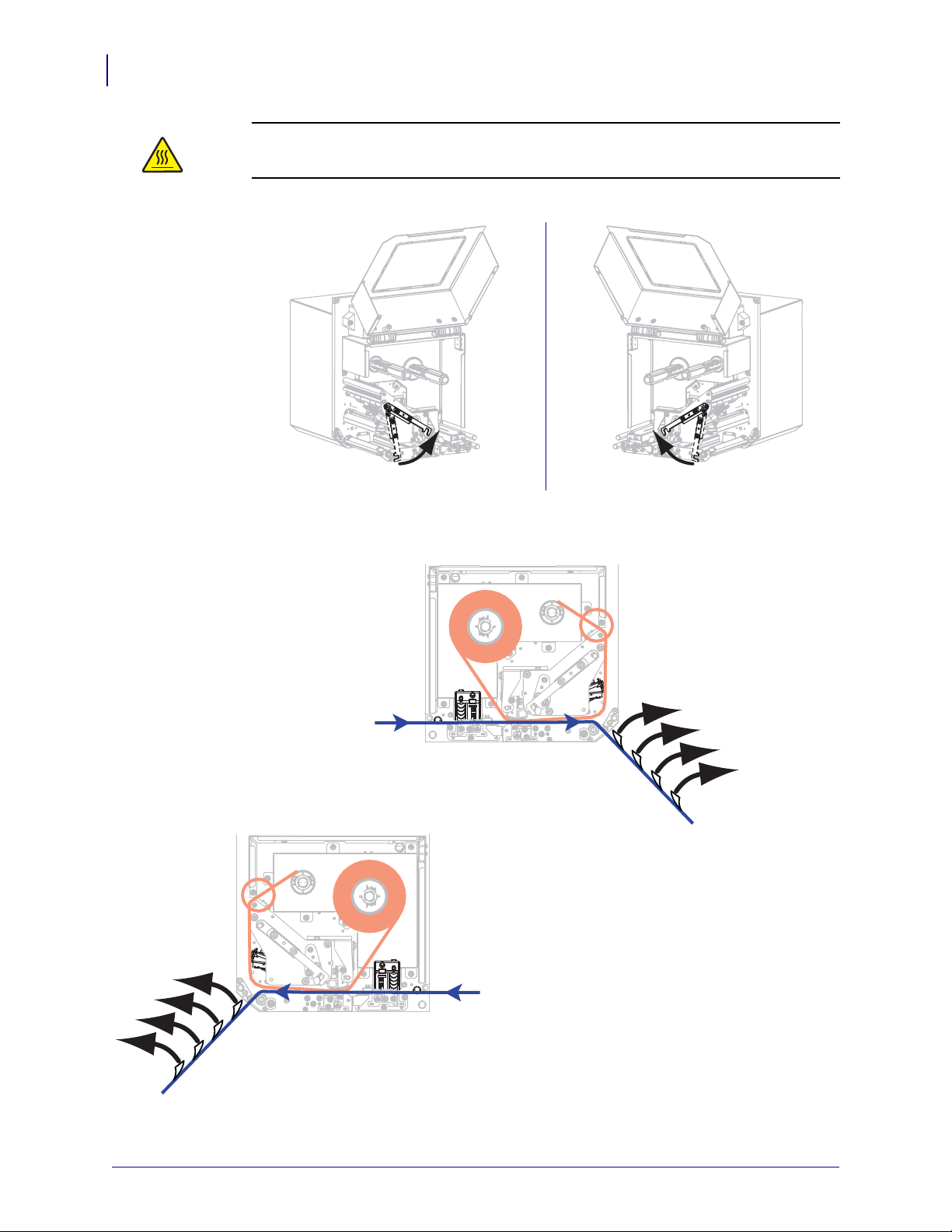
Printer Configuration and Adjustment
LH RH
RH
LH
98
Calibrate the Ribbon and Media Sensors
2.
Caution • The printhead may be hot and could cause severe burns. Allow the
printhead to cool.
Rotate the printhead-release latch to the open position.
3. Extend approximately 8 in. (203 mm) of media past the peel bar. Remove and discard the
labels from the liner on this exposed media.
P1051584-003 ZE500™ User Guide 3/27/14
Page 99

Printer Configuration and Adjustment
LH RH
LH RH
Calibrate the Ribbon and Media Sensors
4. Pull the media back into the print engine so that only the liner is between the media
sensors.
5. Press PLUS (+) to continue.
The control panel displays:
REMOVE RIBBON
6. Remove the ribbon (if used).
7. Rotate the printhead-release latch to the closed position, and close the media door.
99
8. Press PAUSE to begin the media calibration process.
The control panel displays:
CALIBRATING
PLEASE WAIT
When the process is complete, the control panel displays:
RELOAD ALL
9. Rotate the printhead-release latch to the open position.
10. Reload the media and ribbon (if used).
3/27/14 ZE500™ User Guide P1051584-003
Page 100

100
LH RH
Printer Configuration and Adjustment
Calibrate the Ribbon and Media Sensors
11. Rotate the printhead-release latch to the closed position.
12. Close the media door.
13. Press PAUSE to enable printing.
P1051584-003 ZE500™ User Guide 3/27/14
 Loading...