

Page 1

TC52
Touch Computer
Product Reference
Guide
for Android™ 10
MN-003834-02EN Rev. A
Page 2

ZEBRA and the stylized Zebra head are trademarks of Zebra Technologies Corporation, registered in
many jurisdictions worldwide. Google, Android, Google Play and other marks are trademarks of Google
LLC. All other trademarks are the property of their respective owners.
© 2021 Zebra Technologies Corporation and/or its affiliates. All rights reserved.
For further information regarding legal and proprietary statements, go to:
COPYRIGHTS:zebra.com/copyright
WARRANTY:zebra.com/warranty
END USER LICENSE AGREEMENT: zebra.com/eula
Terms of Use
Proprietary Statement
This manual contains proprietary information of Zebra Technologies Corporation and its subsidiaries
(“Zebra Technologies”). It is intended solely for the information and use of parties operating and
maintaining the equipment described herein. Such proprietary information may not be used, reproduced,
or disclosed to any other parties for any other purpose without the express, written permission of Zebra
Technologies.
Product Improvements
Continuous improvement of products is a policy of Zebra Technologies. All specifications and designs are
subject to change without notice.
Liability Disclaimer
Zebra Technologies takes steps to ensure that its published Engineering specifications and manuals are
correct; however, errors do occur. Zebra Technologies reserves the right to correct any such errors and
disclaims liability resulting therefrom.
Limitation of Liability
In no event shall Zebra Technologies or anyone else involved in the creation, production, or delivery of the
accompanying product (including hardware and software) be liable for any damages whatsoever
(including, without limitation, consequential damages including loss of business profits, business
interruption, or loss of business information) arising out of the use of, the results of use of, or inability to
use such product, even if Zebra Technologies has been advised of the possibility of such damages. Some
jurisdictions do not allow the exclusion or limitation of incidental or consequential damages, so the above
limitation or exclusion may not apply to you.
Revision History
Revision Date Description
-01EN Rev.A 7/2020 Initial release.
-02EN Rev. A 7/2021
Update hard reset button combination on page 183.
Update GMS Restricted section on page 166.
2
Page 3

Table of Contents
About This Guide.............................................................................................................................. 12
Configurations............................................................................................................... 12
Notational Conventions................................................................................................. 12
Icon Conventions .......................................................................................................... 13
Service Information ....................................................................................................... 13
Determining Software Versions..................................................................................... 13
Determining the Serial Number..................................................................................... 14
Getting Started.................................................................................................................................. 15
Introduction ................................................................................................................... 15
Unpacking ..................................................................................................................... 15
Device Features............................................................................................................ 16
Setting Up the Device ................................................................................................... 18
Installing a microSD Card....................................................................................... 18
Installing the Battery ............................................................................................... 20
Charging the Battery............................................................................................... 20
Charging Indicators ................................................................................................ 21
Replacing the Battery.................................................................................................... 21
Replacing the microSD Card......................................................................................... 23
Using the Device............................................................................................................................... 24
Home Screen ................................................................................................................ 24
Setting Home Screen Rotation ............................................................................... 25
Status Bar............................................................................................................... 25
Notification Icons.............................................................................................. 25
Status Icons ..................................................................................................... 26
Managing Notifications ........................................................................................... 27
Opening the Quick Access Panel ........................................................................... 28
Quick Access Panel Icons................................................................................ 29
Editing Icons on the Quick Settings Bar ................................................................. 30
3
Page 4

Battery Management..................................................................................................... 30
Checking Battery Status ......................................................................................... 30
Monitoring Battery Usage ....................................................................................... 30
Low Battery Notification.......................................................................................... 31
Interactive Sensor Technology...................................................................................... 31
Waking the Device ........................................................................................................ 31
USB Communication..................................................................................................... 31
Transferring Files.................................................................................................... 32
Transferring Photos ................................................................................................ 32
Disconnect from the Host Computer ...................................................................... 32
Settings.............................................................................................................................................. 33
Accessing Settings........................................................................................................ 33
Display Settings ............................................................................................................ 33
Setting the Screen Brightness Manually................................................................. 33
Setting the Screen Brightness Automatically.......................................................... 33
Setting Night Light .................................................................................................. 33
Setting Screen Rotation.......................................................................................... 34
Setting Screen Timeout .......................................................................................... 34
Setting Font Size .................................................................................................... 35
Notification LED Brightness Level .......................................................................... 35
Touch Panel Mode ................................................................................................. 35
Setting the Date and Time ............................................................................................ 36
General Sound Setting.................................................................................................. 36
Sound Options........................................................................................................ 37
Setting Wake-Up Sources............................................................................................. 37
Remapping a Button ..................................................................................................... 38
Remappable Keys......................................................................................................... 38
Keyboards..................................................................................................................... 38
Keyboard Configuration.......................................................................................... 39
Enabling Keyboards ......................................................................................... 39
Switching Between Keyboards......................................................................... 39
Using the Android and Gboard Keyboards............................................................. 39
Edit Text ........................................................................................................... 39
Entering Numbers, Symbols, and Special Characters ..................................... 39
Using the Enterprise Keyboard............................................................................... 39
Numeric Tab..................................................................................................... 40
Alpha Tab......................................................................................................... 40
Additional Character Tab ................................................................................. 40
Scan Tab.......................................................................................................... 40
Language Usage........................................................................................................... 40
Changing the Language Setting ............................................................................. 40
4
Page 5

Adding Words to the Dictionary .............................................................................. 40
Notifications................................................................................................................... 41
Setting App Notifications ........................................................................................ 41
Viewing Notification Settings for All Apps ........................................................ 41
Controlling Lock Screen Notifications .............................................................. 42
Blink Light......................................................................................................... 42
Applications ...................................................................................................................................... 43
Accessing Apps............................................................................................................. 46
Switching Between Recent Apps............................................................................ 46
Battery Manager............................................................................................................ 46
Opening Battery Manager ...................................................................................... 46
Battery Manager Information Tab........................................................................... 47
Battery Manager Swap Tab.................................................................................... 48
Camera ......................................................................................................................... 49
Taking Photos......................................................................................................... 49
Taking a Panoramic Photo ..................................................................................... 50
Recording Videos ................................................................................................... 50
Photo Settings ........................................................................................................ 51
Rear Camera Photo Settings ........................................................................... 51
Front Camera Photo Settings........................................................................... 52
Video Settings ........................................................................................................ 53
Rear Camera Video Settings ........................................................................... 53
Front Camera Video Settings........................................................................... 54
DataWedge Demonstration........................................................................................... 55
Scanner Selection .................................................................................................. 55
PTT Express Voice Client ............................................................................................. 56
PTT Express User Interface ................................................................................... 56
PTT Audible Indicators ........................................................................................... 57
PTT Notification Icons ............................................................................................ 57
Enabling PTT Communication................................................................................ 57
Selecting a Talk Group ........................................................................................... 58
PTT Communication............................................................................................... 58
Creating a Group Call ...................................................................................... 58
Responding with a Private Response .............................................................. 59
Disabling PTT Communication ............................................................................... 59
RxLogger....................................................................................................................... 60
RxLogger Configuration.......................................................................................... 60
Configuration File ................................................................................................... 60
Enabling Logging.................................................................................................... 60
Disabling Logging ................................................................................................... 60
Extracting Log Files ................................................................................................ 60
5
Page 6

Backing Up ............................................................................................................. 60
RxLogger Utility ...................................................................................................... 61
Initiating the Main Chat Head........................................................................... 61
Removing the Main Chat Head ........................................................................ 61
Viewing Logs.................................................................................................... 61
Removing a Sub Chat Head Icon..................................................................... 61
Backing Up In Overlay View............................................................................. 61
Sound Recorder............................................................................................................ 62
Data Capture ..................................................................................................................................... 63
Imaging ......................................................................................................................... 63
Digital Camera .............................................................................................................. 63
Linear Imager................................................................................................................ 64
Operational Modes ................................................................................................. 64
RS5100 Ring Scanner .................................................................................................. 65
RS6000 Bluetooth Ring Scanner .................................................................................. 65
DS3678 Digital Scanner................................................................................................ 66
LI3678 Linear Scanner.................................................................................................. 66
DS2278 Digital Scanner................................................................................................ 67
Scanning Considerations .............................................................................................. 67
Scanning with Internal Imager....................................................................................... 67
Scanning with Internal Camera..................................................................................... 69
Scanning with RS6000 Bluetooth Ring Scanner........................................................... 71
Scanning with RS5100 Ring Scanner........................................................................... 72
Scanning with the DS3678 Bluetooth Scanner ............................................................. 74
Scanning with LI3678 Linear Imager............................................................................. 74
Scanning with DS2278 Digital Scanner ........................................................................ 75
Pairing the Bluetooth Ring Scanner.............................................................................. 76
Pairing Using Near Field Communication............................................................... 76
Pairing in HID Mode Using Near Field Communication.......................................... 77
Pairing Using Simple Serial Interface ..................................................................... 78
Pairing Using Bluetooth Human Interface Device .................................................. 79
Pairing a Bluetooth Scanner ......................................................................................... 80
Pairing Using Simple Serial Interface ..................................................................... 80
Pairing Using Bluetooth Human Interface Device .................................................. 80
DataWedge ................................................................................................................... 81
Enabling DataWedge.............................................................................................. 81
Disabling DataWedge............................................................................................. 81
Supported Decoders............................................................................................... 82
...................................................................................................................................... 84
6
Page 7

Wireless............................................................................................................................................. 85
Wireless Local Area Networks ...................................................................................... 85
Connecting to a Wi-Fi Network............................................................................... 86
Removing a Wi-Fi Network..................................................................................... 86
WLAN Configuration ..................................................................................................... 86
Configuring a Secure Wi-Fi Network ...................................................................... 86
Manually Adding a Wi-Fi Network .......................................................................... 87
Configuring for a Proxy Server ............................................................................... 88
Configuring the Device to Use a Static IP Address ................................................ 89
Wi-Fi Preferences................................................................................................... 89
Additional Wi-Fi Settings ........................................................................................ 89
Wi-Fi Direct............................................................................................................. 90
Bluetooth....................................................................................................................... 90
Adaptive Frequency Hopping ................................................................................. 91
Security................................................................................................................... 91
Bluetooth Profiles ................................................................................................... 92
Bluetooth Power States .......................................................................................... 93
Bluetooth Radio Power........................................................................................... 93
Enabling Bluetooth ........................................................................................... 93
Disabling Bluetooth .......................................................................................... 93
Discovering Bluetooth Device(s) ............................................................................ 93
Changing the Bluetooth Name ............................................................................... 94
Connecting to a Bluetooth Device .......................................................................... 94
Selecting Profiles on the Bluetooth Device............................................................. 94
Unpairing a Bluetooth Device ................................................................................. 94
Cast............................................................................................................................... 94
Near Field Communications.......................................................................................... 95
Reading NFC Cards ............................................................................................... 95
Sharing Information Using NFC.............................................................................. 96
Enterprise NFC Settings......................................................................................... 97
Accessories....................................................................................................................................... 98
Battery Charging ......................................................................................................... 101
Main Battery Charging.......................................................................................... 101
Spare Battery Charging ........................................................................................ 101
Charging Temperature ......................................................................................... 102
1-Slot USB Charge Cradle.......................................................................................... 103
Setup .................................................................................................................... 104
Charging the Device ............................................................................................. 104
Inserting a Device with Rugged Boot into Cradle ................................................. 105
1-Slot Workstation Docking Cradle ............................................................................. 106
7
Page 8

Setup .................................................................................................................... 108
Ethernet Setup...................................................................................................... 109
Scanner Setup...................................................................................................... 109
Security................................................................................................................. 109
Using the Workstation Cradle............................................................................... 109
Changing Monitor Resolution ............................................................................... 109
Charging the Device ............................................................................................. 109
Inserting a TC5X with Rugged Boot into Cradle ......................................................... 110
Setup .................................................................................................................... 112
Ethernet Settings............................................................................................ 112
Configuring Ethernet Proxy Settings .............................................................. 112
Configuring Ethernet Static IP Address.......................................................... 113
4-Slot Charge Only Cradle with Battery Charger ........................................................ 117
Setup .................................................................................................................... 118
Charging the Device ............................................................................................. 118
Inserting a TC52 with Rugged Boot into Cradle ................................................... 120
5-Slot Charge Only Cradle.......................................................................................... 121
Setup .................................................................................................................... 122
Charging the Device ............................................................................................. 122
Inserting a Device with Rugged Boot into Cradle ................................................. 123
5-Slot Ethernet Cradle................................................................................................. 124
Setup .................................................................................................................... 125
Daisy-chaining Ethernet Cradles .......................................................................... 125
Ethernet Settings .................................................................................................. 126
Configuring Ethernet Proxy Settings .............................................................. 126
Configuring Ethernet Static IP Address.......................................................... 127
Charging the Device ............................................................................................. 127
Inserting a TC52 with Rugged Boot into Cradle ................................................... 128
Establishing Ethernet Connection .................................................................. 128
LED Indicators ...................................................................................................... 129
4-Slot Battery Charger ................................................................................................ 130
Setup .................................................................................................................... 130
Single Charger Setup..................................................................................... 130
Two Charger Setup ........................................................................................ 131
Charging Spare Batteries ..................................................................................... 132
Rugged Boot ............................................................................................................... 134
Installation ............................................................................................................ 134
Installing Stylus..................................................................................................... 135
Charging with Cradles .......................................................................................... 136
Basic Hand Strap Kit................................................................................................... 138
Installation ............................................................................................................ 138
8
Page 9

Removal ............................................................................................................... 139
2.5 mm Audio Adapter ................................................................................................ 141
3.5 mm Audio Adapter ................................................................................................ 142
Rugged Charge/USB Cable........................................................................................ 143
Connecting to TC52.............................................................................................. 143
Connecting to TC52 with Rugged Boot ................................................................ 144
USB Communication ............................................................................................ 145
Charging the Device ............................................................................................. 145
Disconnecting the Rugged Charge/USB Cable.................................................... 146
Trigger Handle ............................................................................................................ 147
Installing the Rugged Boot ................................................................................... 147
Installing the Optional Lanyard ............................................................................. 149
Inserting the Device into the Trigger Handle ........................................................ 149
Removing the Device from the Trigger Handle .................................................... 150
Power Supply.............................................................................................................. 152
5-Slot Cradle Rack Installation.................................................................................... 153
4-Slot Battery Chargers Rack Installation ................................................................... 156
Rack Mount Installation............................................................................................... 159
Wall Installation........................................................................................................... 162
Bottom Tray Assembly ......................................................................................... 162
Bracket Wall Mounting.......................................................................................... 162
Application Deployment................................................................................................................. 164
Security ....................................................................................................................... 164
Secure Certificates...................................................................................................... 164
Installing a Secure Certificate ..................................................................................... 164
Configuring Credential Storage Settings .............................................................. 165
Development Tools ..................................................................................................... 165
Android Application Development ........................................................................ 165
Development Workstation .............................................................................. 165
Enabling Developer Options .......................................................................... 165
EMDK for Android................................................................................................. 166
StageNow ............................................................................................................. 166
GMS Restricted........................................................................................................... 166
ADB USB Setup.......................................................................................................... 166
Enabling USB Debugging..................................................................................... 166
Application Installation ................................................................................................ 167
Installing Applications Using the USB Connection ............................................... 167
Installing Applications Using the Android Debug Bridge ...................................... 168
Installing Applications Using a microSD Card ...................................................... 168
Uninstalling an Application ................................................................................... 169
9
Page 10

Performing a System Update...................................................................................... 169
Downloading the System Update Package .......................................................... 170
Performing a System Update Using microSD Card.............................................. 170
Performing a System Update Using ADB............................................................. 170
Verifying System Update Installation.................................................................... 171
Enterprise Reset ......................................................................................................... 171
Performing an Enterprise Reset From Device Settings........................................ 171
Downloading the Enterprise Reset Package ........................................................ 172
Performing an Enterprise Reset Using microSD Card ......................................... 172
Performing an Enterprise Reset Using ADB......................................................... 172
Performing a Factory Reset ........................................................................................ 173
Downloading the Factory Reset Package ............................................................ 173
Performing a Factory Reset Using microSD Card................................................ 173
Performing a Factory Reset Using ADB ............................................................... 174
Storage........................................................................................................................ 175
Random Access Memory ..................................................................................... 175
Viewing Memory............................................................................................. 175
Internal Storage .................................................................................................... 175
Viewing Internal Storage ................................................................................ 175
External Storage................................................................................................... 176
Viewing External Storage............................................................................... 176
Formatting a microSD Card ........................................................................... 176
Formatting a microSD Card as Internal Memory............................................ 176
Enterprise Folder .................................................................................................. 176
Managing Apps ........................................................................................................... 177
App Details ........................................................................................................... 177
Managing Downloads.................................................................................................. 177
Maintenance and Troubleshooting ............................................................................................... 178
Maintaining the Device................................................................................................ 178
Display Best Practices ................................................................................................ 178
Image Retention ................................................................................................... 178
Battery Safety Guidelines ..................................................................................... 179
Cleaning Instructions................................................................................................... 179
Cleaning and Disinfecting Guidelines................................................................... 179
Approved Cleaning and Disinfectant Agents for TC52 ......................................... 180
Approved Cleaning and Disinfectant Agents for TC52-HC................................... 180
Special Cleaning Notes ........................................................................................ 180
Cleaning Frequency ............................................................................................. 181
Cleaning the Device.................................................................................................... 181
Housing ................................................................................................................ 181
10
Page 11

Display.................................................................................................................. 181
Camera and Exit Window ..................................................................................... 181
Battery Guide Slots............................................................................................... 181
Battery Connector and Locating Magnet Cleaning............................................... 181
Cleaning Cradle Connectors....................................................................................... 182
Troubleshooting .......................................................................................................... 182
Resetting the Device ............................................................................................ 182
Performing a Soft Reset................................................................................. 182
Performing a Hard Reset ............................................................................... 183
TC52..................................................................................................................... 183
1-Slot Charge Only Cradle ................................................................................... 185
1-Slot Workstation Docking Cradle....................................................................... 186
2-Slot USB/Ethernet Cradle.................................................................................. 187
4-Slot Charge Only Cradle with Battery Charger Troubleshooting....................... 188
5-Slot Charge Only Cradle Troubleshooting......................................................... 188
5-Slot Ethernet Cradle Troubleshooting ............................................................... 189
4-Slot Battery Charger Troubleshooting ............................................................... 189
Technical Specifications................................................................................................................ 191
Decode Distances ................................................................................................ 191
I/O Connector Pin-Outs ........................................................................................ 192
1-Slot Charge Only Cradle Technical Specifications............................................ 193
1-Slot Workstation Docking Cradle Technical Specifications ............................... 193
2-Slot USB/Ethernet Cradle Technical Specifications .......................................... 194
4-Slot Charge Only Cradle with Battery Charger Technical Specifications .......... 194
5-Slot Charge Only Cradle Technical Specifications............................................ 195
5-Slot Ethernet Cradle Technical Specifications .................................................. 195
4-Slot Battery Charger Technical Specifications .................................................. 196
Trigger Handle Technical Specifications .............................................................. 196
Rugged Charge/USB Cable Technical Specifications.......................................... 197
11
Page 12

About This Guide
This guide provides information about setting up and using the TC52 touch computer. Some screens
shown in this guide may differ from the actual screens shown on the device.
Configurations
This guide covers the following configurations:
Table 1 Configurations
Configuration Radios Display Memory
TC520K-1 WLAN: 802.11
a/b/g/n//ac/d/h/i/r/k/v3/w
WPAN: Bluetooth v5.0
Low Energy
TC520K-1 WLAN: 802.11
a/b/g/n//ac/d/h/i/r/k/v3/w
WPAN: Bluetooth v5.0
Low Energy
5.0” High
Definition
(1280 x
720) LCD
5.0” High
Definition
(1280 x
720) LCD
4 GB RAM /
32 GB Flash
4 GB RAM /
32 GB Flash
Notational Conventions
Notational conventions are used to highlight important information.
• Bold text is used to highlight the following:
• Dialog box, window and screen names
• Drop-down list and list box names
• Check box and radio button names
• Icons on a screen
Data Capture
Options
2D imager
(SE-4710) and
integrated NFC
2D imager
(SE-4710) and
integrated NFC
Operating
System
Android-based,
Google™ Mobile
Services (GMS)
10
Android-based,
AOSP 10 (China
only)
• Key names on a keypad
• Button names on a screen.
• Bullets (•) indicate:
• Action items
• Lists of alternatives
12
Page 13

• Lists of required steps that are not necessarily sequential.
• Sequential lists (for example, those that describe step-by-step procedures) appear as numbered lists.
Icon Conventions
The following icons are used throughout the document. The icons and their associated meanings are
described below.
NOTE: The text here indicates information that is supplemental for the user to know and that is not required to
complete a task.
IMPORTANT: The text here indicates information that is important for the user to know.
CAUTION: If the precaution is not heeded, the user could receive minor or moderate injury.
WARNING: If danger is not avoided, the user CAN be seriously injured or killed.
About This Guide
DANGER: If danger is not avoided, the user WILL be seriously injured or killed.
Service Information
If you have a problem with your equipment, contact Customer Support for your region. Contact information is
available at: zebra.com/support
When contacting support, please have the following information available:
• Serial number of the unit (found on manufacturing label)
• Model number or product name (found on manufacturing label)
• Software type and version number
Customer Support responds to calls by email or telephone within the time limits set forth in support
agreements.
If the problem cannot be solved by Customer Support, the user may need to return the equipment for servicing
and will be given specific directions. We are not responsible for any damages incurred during shipment if the
approved shipping container is not used. Shipping the units improperly can possibly void the warranty. If
applicable, remove the microSD card from the device before shipping for service.
If the device was purchased from a business partner, contact that business partner for support.
.
Determining Software Versions
Before contacting Customer Support, determine the current software version on your device.
1. Swipe down from the Status bar with two fingers to open the Quick Access panel, and then touch .
2. Touch About phone.
3. Scroll to view the following information:
• Battery information
13
Page 14

About This Guide
• Emergency information
• SW components
• Legal information
• Model & hardware
• Android version
• Android security patch level
• Android security patch version
• Kernel version
• Build number
Determining the Serial Number
Before contacting Customer Support, determine the serial number of your device.
1. Swipe down from the Status bar with two fingers to open the Quick Access panel, and then touch .
2. Touch About phone > Model & hardware > Serial number.
14
Page 15

Getting Started
Introduction
This section provides information for getting the device up and running for the first time.
Unpacking
1. Carefully remove all protective material from the device and save the shipping container for later
storage and shipping.
2. Verify that the following were received:
• Touch computer
• >
15.48 Watt hours (typical) / > 4,150 mAh PowerPrecision+ Lithium-ion battery
• Regulatory Guide.
3. Inspect the equipment for damage. If any equipment is missing or damaged, contact the Customer
Support center immediately.
4. Prior to using the device for the first time, remove the protective shipping film that covers the scan
window, display and camera window.
15
Page 16

Device Features
Figure 1 Front View
Getting Started
14
13
5
4
3
2
1
8
6
7
8
9
10
11
12
Number Item Function
1 Front Camera Takes photos and videos.
2 Receiver Use for audio playback in Handset mode.
3 Data Capture LED Indicates data capture status.
4 Microphone Use for communications in Speakerphone mode.
5 Proximity Sensor Determines proximity for turning off display when in handset mode.
6 Light Sensor Determines ambient light for controlling display backlight intensity.
7 Charging/Notification LED Indicates battery charging status while charging and application
generated notifications.
8 ActiveEdge Touch Zone Programmable dynamic soft key positioned near the perimeter of
the display for one-touch access to a frequently used application or
function.
9 Touch Screen Displays all information needed to operate the device.
10 Speaker Provides audio output for video and music playback. Provides
audio in speakerphone mode.
11 Interface Connector Provides USB host and client communications, audio and device
charging via cables and accessories.
CAUTION: Do not remove the interface connector to ensure proper
device sealing.
16
Page 17

Getting Started
Number Item Function
12 Microphone Use for communications in Handset mode.
13 Scan Button Initiates data capture (programmable).
14 PTT Button Initiates push-to-talk communications (programmable).
Figure 2 Rear View
15
16
19
27
26
25
24
18
19
20
21
23
22
17
Number Item Function
15 Battery PowerPrecision+ Lithium-ion battery.
16 Basic Hand Strap Mount Provides mounting point for Basic Hand Strap accessory.
17 NFC Antenna Provides communication with other NFC-enabled devices.
18 Scan Button Initiates data capture (programmable).
19 Battery Release Latches Press to remove the battery.
20 Volume Up/Down Button Increase and decrease audio volume (programmable).
21 Rear Camera Takes photos and videos.
22 Camera Flash Provides illumination for the camera.
23 Power Button Turns the display on and off. Press and hold to reset the device,
power off or swap battery.
24 Microphone Use for noise cancellation.
25 Exit Window Provides data capture using the imager.
26 Headset Jack For audio output to headset.
27 Programmable Button Programmable.
17
Page 18

Setting Up the Device
To start using the device for the first time:
1. Install a micro secure digital (SD) card (optional).
2. Install hand strap (optional).
3. Install the battery.
4. Charge the device.
5. Power on the device.
Installing a microSD Card
The microSD card slot provides secondary non-volatile storage. The slot is located under the battery pack.
Refer to the documentation provided with the card for more information, and follow the manufacturer’s
recommendations for use.
CAUTION: Follow proper electrostatic discharge (ESD) precautions to avoid damaging the microSD card.
Proper ESD precautions include, but are not limited to, working on an ESD mat and ensuring that the operator
is properly grounded.
Getting Started
1. Lift the access door.
2. Slide the microSD card holder to the unlock position.
18
Page 19

Getting Started
Lift the microSD card holder.
3.
4. Insert the microSD card into the card holder door ensuring that the card slides into the holding tabs on each
side of the door.
5. Close the microSD card holder and slide into the lock position.
CAUTION: Access door must be replaced and securely seated to ensure proper device sealing.
6. Re-install the access door.
19
Page 20

Installing the Battery
1. Insert the battery, bottom first, into the battery compartment in the back of the device.
2. Press the battery down into the battery compartment until the battery release latches snap into place.
Getting Started
Charging the Battery
Before using the device for the first time, charge the main battery until the green Charging/Notification light
emitting diode (LED) remains lit. To charge the device use a cable or a cradle with the appropriate power
supply. For information about the accessories available for the device see Accessories for more information.
The battery charges from fully depleted to 90% in approximately 2.5 hours, and from fully depleted to 100% in
approximately three hours.
NOTE: In many cases the 90% charge provides plenty of charge for daily use. A full 100% charge lasts for
approximately 14 hours of use. To achieve the best fast charging results use only Zebra charging accessories
and batteries. Charge batteries at room temperature with the device in sleep mode.
Charge batteries in temperatures from 5°C to 40°C (41°F to 104°F). The device or accessory always performs
battery charging in a safe and intelligent manner. At higher temperatures (for example: approximately +37°C
(+98°F)) the device or accessory may for small periods of time alternately enable and disable battery charging
to keep the battery at acceptable temperatures. The device or accessory indicates when charging is disabled
due to abnormal temperatures via its LED and a notification appears on the display.
To charge the main battery:
1. Connect the charging accessory to the appropriate power source.
2. Insert the device into a cradle or attach to a cable. The device turns on and begins charging. The
Charging/Notification LED blinks amber while charging, then turns solid green when fully charged.
20
Page 21

Charging Indicators
Table 2 Charging/Notification LED Charging Indicators
State LED Indication
Off Device is not charging. Device is not inserted correctly in the
Slow Blinking Amber (1 blink
every 4 seconds)
Slow Blinking Red (1 blink every
4 seconds)
Solid Green Charging complete.
Solid Red Charging complete but the battery is at end of useful life.
Getting Started
cradle or connected to a power source. Charger/cradle is not
powered.
Device is charging.
Device is charging but the battery is at end of useful life.
Fast Blinking Amber (2
blinks/second)
Fast Blinking Red (2
blinks/second)
Zebra Visibility Services
The device captures and provides device analytics to a system administrator. The first time the device boots
(or after a Factory reset), the Zebra Services agreement screen displays.
1. Touch the Device Data switch to disable the device from sending analytics data.
2. Touch OK.
Replacing the Battery
Charging error, for example:
• Temperature is too low or too high.
• Charging has gone on too long without completion
(typically eight hours).
Charging error but the battery is at end of useful life, for
example:
• Temperature is too low or too high.
• Charging has gone on too long without completion
(typically eight hours).
NOTE: User modification of the device, particularly in the battery well, such as labels, asset tags, engravings,
stickers, etc., may compromise the intended performance of the device or accessories. Performance levels
such as sealing (Ingress Protection (IP)), impact performance (drop and tumble), functionality, temperature
resistance, etc. could be effected. DO NOT put any labels, asset tags, engravings, stickers, etc. in the battery
well.
CAUTION: Do not add or remove microSD card during battery replacement.
1. Press the Power button until the menu appears.
2. Touch Battery Swap.
21
Page 22

Getting Started
Follow the on-screen instructions.
3.
WARNING: Do not remove the battery until after the red LED completely turns off. Loss of data may result.
4. Wait for the red LED to completely turn off.
5. If hand strap is attached, remove hand strap.
6. Press the two battery latches in.
7. Lift the battery from the device.
CAUTION: Replace the battery within 75 seconds. After 75 seconds the device reboots and data may be lost.
8. Insert the replacement battery, bottom first, into the battery compartment in the back of the device.
9. Press the battery down until the battery release latches snap into place.
10. Replace the hand strap, if required.
11. Press the Power button to turn on the device.
22
Page 23

Replacing the microSD Card
To replace the microSD card:
1. Press the Power button until the menu appears.
2. Touch Power off.
3. Touch OK.
4. If hand strap is attached, slide the hand strap clip up toward the top of the device and then lift.
5. Press the two battery latches in.
6. Lift the battery from the device.
7. Lift the access door.
Getting Started
8. Remove microSD card from holder.
9. Insert the replacement microSD card.
CAUTION: Access door must be replaced and securely seated to ensure proper device sealing.
10. Replace the access door.
11. Insert the battery, bottom first, into the battery compartment in the back of the device.
12. Press the battery down until the battery release latches snap into place.
13. Replace the hand strap, if required.
14. Press and hold the Power button to turn on the device.
23
Page 24

Using the Device
Home Screen
Turn on the device to display the Home screen. Depending on how your system administrator configured
your device, your Home screen may appear differently than the graphics in this section.
After a suspend or screen time-out, the Home screen displays with the lock slider. Touch the screen and
slide up to unlock.
The Home screen provides four additional screens to place widgets and shortcuts. Swipe the screen left or
right to view the additional screens.
NOTE: By default, AOSP devices do not have the same icons on the Home screen as GMS devices. Icons
are shown below for example only.
Home screen icons can be configured by the user and may look different than shown.
Figure 3 Home Screen
24
Page 25

1 Status Bar Displays the time, status icons (right side), and notification icons (left side).
For more information see Notification Icons on page 25 and Managing
Notifications on page 27.
2 Widgets Launches stand-alone apps that run on the Home screen.
3 Shortcut Icons Opens apps installed on the device.
4 Folder Contains apps.
5 Back Displays the previous screen.
6 Home Displays the Home screen.
7 Recent Displays recently used applications.
Setting Home Screen Rotation
By default, the Home screen rotation is disabled.
1. Touch and hold anywhere on the Home screen until the options appear.
2. Touch Home settings.
3. Touch the Allow Home screen rotation switch.
Using the Device
4. Touch the Home button.
5. Rotate the device.
Status Bar
The Status bar displays the time, notification icons (left side), and status icons (right side).
If there are more notifications than can fit in the Status bar, a dot displays indicating that more notifications
exist. Swipe down from the Status bar to open the Notification panel and view all notifications and status.
Figure 4 Notification and Status Icons
1 Notification Icons. See Notification Icons on page 25.
2 Status Icons. See Status Icons on page 26.
Notification Icons
Notification icons indicate app events and messages.
1
2
25
Page 26

Using the Device
Table 3 Notification Icons
Icon Description
Main battery is low.
More notifications are available for viewing.
Data is syncing.
Indicates an upcoming event. AOSP devices only.
Indicates an upcoming event. GMS devices only.
Open Wi-Fi network is available.
Audio is playing.
Problem with sign-in or sync has occurred.
Device is uploading data.
Status Icons
Status icons display system information for the device.
Table 4 Status Icons
Animated: the device is downloading data. Static: the download is complete.
Device is connected to or disconnected from a virtual private network (VPN).
Preparing internal storage by checking it for errors.
USB debugging is enabled on the device.
BT Headset is connected to the device.
PTT Express Voice client status. See the PTT Express PTT Notification Icons for a
complete list.
Indicates the RxLogger app is running.
Indicates the Bluetooth scanner is connected to the device.
Indicates the ring scanner is connected to the device in HID mode.
Icon Description
Alarm is active.
Main battery is fully charged.
Main battery is partially drained.
26
Page 27

Using the Device
Table 4 Status Icons (Continued)
Icon Description
Main battery charge is low.
Main battery charge is very low.
Main battery is charging.
All sounds, except media and alarms, are muted. Vibrate mode is active.
Do Not Disturb mode active.
Airplane Mode is active. All radios are turned off.
Bluetooth is on.
The device is connected to a Bluetooth device.
Connected to a Wi-Fi network. Indicates the Wi-Fi version number.
Not connected to a Wi-Fi network or no Wi-Fi signal.
Connected to an Ethernet network.
Speakerphone enabled.
Managing Notifications
Notification icons report the arrival of new messages, calendar events, alarms, and ongoing events. When
a notification occurs, an icon appears in the Status bar with a brief description. See Notification Icons for a
list of possible notification icons and their description.
1. To view a list of all notifications, open the Notification panel by dragging the Status bar down from the
top of the screen.
27
Page 28

Using the Device
Quick Settings Bar
To respond to a notification, open the Notification panel and then touch a notification. The Notification
2.
panel closes and the corresponding app opens.
3. To manage recent or frequently used notifications, open the Notification panel and then touch Manage
notifications. Touch the toggle switch next to an app to turn off all notifications, or touch an app for
more notification options.
4. To clear all notifications, open the Notification panel and then touch CLEAR ALL. All event-based
notifications are removed. Ongoing notifications remain in the list.
5. To close the Notification panel, swipe the Notification panel up.
Opening the Quick Access Panel
Use the Quick Access panel to access frequently used settings (for example, Airplane mode). To get to the
Quick Access Panel:
• If the device is locked, swipe down once.
• If the device is unlocked, swipe down once with two fingers, or twice with one finger.
• If the Notification panel is open, swipe down from the Quick Settings bar.
28
Page 29

Using the Device
NOTE: Not all icons are pictured. Icons may vary.
Quick Access Panel Icons
• Display brightness - Use the slider to decrease or increase the brightness of the screen.
• Wi-Fi network - Turn Wi-Fi on or off. To open Wi-Fi settings, touch the Wi-Fi network name.
• Bluetooth settings - Turn Bluetooth on or off. To open Bluetooth settings, touch Bluetooth.
• Battery saver - Turn Battery saver mode on or off. When Battery saver mode is on the performance of
the device is reduced to preserve battery power.
• Invert colors - Invert the display colors.
• Do not disturb - Control how and when to receive notifications.
• Airplane mode - Turn Airplane mode on or off. When Airplane mode is on the device does not connect
to Wi-Fi or Bluetooth.
• Auto-rotate - Lock the device’s orientation in portrait or landscape mode or set to automatically rotate.
• Flashlight - Turn flashlight on or off. Turn camera flash on or off.
• Night Light - Tint the screen amber to make it easier to look at the screen in dim light. Set Night Light to
turn on automatically from sunset to sunrise, or at other times.
• Screen Cast - Share phone content on Chromecast or a television with Google Cast built-in. Touch cast
screen to display a list of devices, then touch a device to begin casting.
• Dark Theme - Toggles dark theme on and off. Dark themes reduce the luminance emitted by the
screen, while meeting minimum color contrast ratios. It helps improve visual ergonomics by reducing
eye strain, adjusting brightness to current lighting conditions, and facilitating screen use in dark
environments, while conserving battery power.
• Grayscale - Turn grayscale on and off. Grayscale turns the screen black and white, reducing phone
distractions and improving battery life.
• Focus mode - Turn on to pause distracting apps. To open Focus mode settings, touch and hold.
29
Page 30

Using the Device
Editing Icons on the Quick Settings Bar
The first several setting tiles from the Quick Access panel become the Quick Settings bar.
• Open the Quick Access panel and touch to edit, add, or remove settings tiles.
Battery Management
Observe the recommended battery optimization tips for your device.
• Set the screen to turn off after a short period of non-use.
• Reduce screen brightness.
• Turn off all wireless radios when not in use.
• Turn off automatic syncing for Email, Calendar, Contacts, and other apps.
• Minimize use of apps that keep the device from suspending, for example, music and video apps.
NOTE: Before checking the battery charge level, remove the device from any AC power source (cradle or
cable).
Checking Battery Status
• Open Settings and touch About phone > Battery Information.
Or, swipe up from the bottom of the screen and touch to open the Battery Manager app. See
Battery Manager on page 46.
• Battery present status indicates if the battery is present.
• Battery level lists the battery charge (as a percentage of fully charged).
• Swipe down with two fingers from the status bar to open the quick access panel.
• Battery percentage is displayed next to the battery icon.
Monitoring Battery Usage
The Battery screen provides battery charge details and power management options to extend battery life.
1. Go to Settings.
2. Touch Battery.
Display battery information and power management options for a specific app.
1. Go to Settings.
2. Touch Apps & notifications.
3. Touch an app.
4. Touch Advanced > Battery.
Different apps display different information. Some apps include buttons that open screens with settings to
adjust power use. Use the DISABLE or FORCE CLOSE buttons to turn off apps that consume too much
power. Use the DISABLE or FORCE STOP buttons to turn off apps that consume too much power.
30
Page 31

Using the Device
Low Battery Notification
When the battery charge level drops below 18%, the device displays a notice to connect the device to
power. The user should charge the battery using one of the charging accessories.
When the battery charge drops below 10%, the device displays a notice to connect the device to power.
The user must charge the battery using one of the charging accessories.
When the battery charge drops below 4%, the device turns off. The user must charge the battery using one
of the charging accessories.
• Enable Battery Saver mode. Swipe down from the Status bar and then touch Battery saver.
• Disable DataWedge Launcher profile.
Interactive Sensor Technology
The device contains sensors that monitor movement, orientation and ambient light.
• Gyroscope - Measures angular rotational velocity to detect rotation of the device.
• Accelerometer - Measures the linear acceleration of movement to detect the orientation of the device.
• Digital Compass - The digital compass or magnetometer provides simple orientation in relation to the
Earth's magnetic field. As a result, the device always knows which way is North so it can auto rotate
digital maps depending on the physical orientation of the device.
• Light Sensor - Detects ambient light and adjusts the screen brightness.
• Proximity Sensor - Detects the presence of nearby objects without physical contact.
In order to take advantage of these sensors, applications use API commands. Refer to the Google Android
Sensor APIs for more information. For information on the Zebra Android EMDK, go to:
techdocs.zebra.com
Waking the Device
The device goes into Suspend mode when you press the Power button or after a period of inactivity (set in
the Display settings window).
1. To wake the device from Suspend mode, press the Power button.
The Lock screen displays.
2. Swipe the screen up to unlock.
• If the Pattern screen unlock feature is enabled, the Pattern screen appears instead of the Lock screen.
• If the PIN or Password screen unlock feature is enabled, enter the PIN or password after unlocking the
screen.
NOTE: If you enter the PIN, password, or pattern incorrectly five times, you must wait 30 seconds before
trying again.
.
If you forget the PIN, password, or pattern contact your system administrator.
USB Communication
Connect the device to a host computer to transfer files between the device and the host computer.
31
Page 32

When connecting the device to a host computer, follow the host computer’s instructions for connecting and
disconnecting USB devices, to avoid damaging or corrupting files. For information on USB communication
accessories available for this device, see Accessories.
Transferring Files
Use Transfer files to copy files between the device and the host computer.
1. Connect the device to a host computer using a USB accessory.
2. On the device, pull down the Notification panel and touch Charging this device via USB.
By default, No data transfer is selected.
3. Touch File Transfer.
NOTE: After changing the setting to File Transfer, and then disconnect the USB cable, the setting reverts
back to No data transfer. If the USB cable is reconnected, select File Transfer again.
4. On the host computer, open a file explorer application.
5. Locate the device as a portable device.
6. Open the SD card or the Internal storage folder.
Using the Device
7. Copy files to and from the device or delete files as required.
Transferring Photos
Use PTP to copy photos from the device to the host computer.
1. Connect the device to a host computer using a USB accessory.
2. On the device, pull down the Notification panel and touch Charging this device via USB.
3. Touch PTP.
4. On the host computer, open a file explorer application.
5. Open the SD card or the Internal storage folder.
6. Copy or delete photos as required.
Disconnect from the Host Computer
CAUTION: Carefully follow the host computer’s instructions to unmount the microSD card and disconnect
USB devices correctly to avoid losing information.
To disconnect the device from the host computer:
1. On the host computer, unmount the device.
2. Remove the device from the USB accessory.
32
Page 33

Settings
Accessing Settings
There are multiple ways to access settings on a device.
• Swipe down with two fingers from the top of the Home screen to open the Quick Access panel and
touch .
• Double-swipe down from the top of the Home screen to open the Quick Access panel and touch .
• Swipe up from the bottom of the Home screen to open APPS and touch Settings.
Display Settings
Use Display settings to change the screen brightness, enable night light, change the background
image, enable screen rotation, set sleep time, and change font size.
Setting the Screen Brightness Manually
Manually set the screen brightness using the touchscreen.
1. Swipe down with two fingers from the Status bar to open the Quick Access panel.
2. Slide the icon to adjust the screen brightness level.
Setting the Screen Brightness Automatically
Automatically adjust the screen brightness using the built-in light sensor.
1. Go to Settings.
2. Touch Display.
3. If disabled, touch Adaptive brightness to automatically adjust the brightness.
By default, Adaptive brightness is enabled. Toggle the switch to disable.
4. Touch the Home button.
Setting Night Light
The Night Light setting tints the screen amber, making the screen easier to look at in low light.
33
Page 34

Go to Settings.
1.
2. Touch Display.
Touch Night Light.
3.
Touch Schedule.
4.
5. Select one of the schedule values:
• None (default)
• Turns on at custom time
• Turns on from sunset to sunrise.
6. By default, Night Light is disabled. Touch TURN ON NOW to enable.
7. Adjust the tint using the Intensity slider.
8. Touch the Home button.
Setting Screen Rotation
Settings
By default, screen rotation is enabled.
1. Go to Settings.
2. Touch Display > Advanced.
3. Touch Auto-rotate screen.
NOTE: To change the Home screen rotation, see Setting Home Screen Rotation on page 25.
4. Touch the Home button.
Setting Screen Timeout
Set the screen sleep time.
1. Go to Settings.
2. Touch Display > Advanced > Screen timeout.
3. Select one of the sleep values.
• 15 seconds
• 30 seconds
• 1 minute (default)
• 2 minutes
• 5 minutes
• 10 minutes
• 30 minutes
34
Page 35

Setting Font Size
Set the size of the font in system apps.
1. Go to Settings.
2. Touch Display > Advanced.
3. Touch Font size.
4. Select one of the font size values.
• Small
• Default
• Large
• Largest.
5. Touch the Home button.
Notification LED Brightness Level
Settings
Set the brightness of the Notification LED.
1. Go to Settings.
2. Touch Display > Advanced.
3. Touch Notification LED Brightness Level.
4. Use the slider to set the brightness value (default: 15).
5. Touch the Home button.
Touch Panel Mode
The device display is able to detect touches using a finger, a conductive-tip stylus, or gloved finger.
NOTE: A glove can be made of medical latex, leather, cotton, or wool.
For optimal performance use a Zebra certified stylus.
1. Go to Settings.
2. Touch Display > Advanced.
3. Touch Touch panel mode.
4. Select:
a. Glove and Finger (Screen Protector off) to use a finger or a gloved finger on the screen without a
screen protector.
b. Stylus and Finger (Screen Protector off) to use a finger or a stylus on the screen without a screen
protector.
c. Finger Only to use a finger on the screen.
d. Glove and Finger (Screen Protector on) to use a finger or a gloved finger on the screen with a screen
protector.
35
Page 36

Stylus and Finger (Screen Protector on) to use a finger or a stylus on the screen with a screen
e.
protector.
5. Touch the Home button.
Setting the Date and Time
You are only required to set the time zone or set the date and time if the wireless LAN does not support
Network Time Protocol (NTP).
1. Go to Settings.
2. Touch System > Date & time.
Touch Date.
3.
4. In the calendar, set today’s date.
5. Touch OK.
6. Touch Time.
Settings
7. Touch the green circle, drag to the current hour and then release.
8. Touch the green circle, drag to the current minute and then release.
9. Touch AM or PM.
10.Touch OK.
11.Touch Use 24-hour format.
12.Touch the Home button.
General Sound Setting
Use the Sound settings to configure media and alarm volumes.
1. Go to Settings.
2. Touch Sound.
3. Touch an option to set sounds.
36
Page 37

Sound Options
• Zebra volume controls
• Ring volume - Controls the ringtone volume.
• Media volume - Controls the music, games, and media volume.
• Alarm volume - Controls the alarm clock volume.
• Notifications volume - Controls the notification volume.
• In call volume - Controls the volume during a call.
• Scanner volume - Controls the scanner volume.
• Volume presets
• - Mutes the ring, notifications, and scanner so that the device does not make sounds or vibrate.
• - All sounds except media and alarms are silenced and vibrate mode is active.
• - Enables all sounds at the user defined levels.
• Do Not Disturb - Mutes some or all sounds and vibrations.
• Shortcut to prevent ringing - Select how the shortcut method prevents ringing.
• Default notification sound - Select a sound to play for all system notifications.
• Default alarm sound - Select a sound to play for alarms.
• Other sounds and vibrations
• Screen locking sounds - Play a sound when locking and unlocking the screen (default – enabled).
• Charging sounds and vibration - Plays a sound and vibrates when power is applied to the device
(default - enabled).
• Touch sounds - Play a sound when making screen selections (default – enabled).
• Touch vibration - Vibrate the device when making screen selections (default – disabled).
• Wireless Emergency alerts - Touch to configure emergency broadcast settings and notifications.
Settings
Setting Wake-Up Sources
By default the device wakes from suspend mode when the user presses the Power button. The device can be
configured to wake when the user presses the PTT or Scan buttons on the left side of the device.
1. Go to Settings.
2. Touch Wake-Up Sources.
• LEFT_TRIGGER_2 - PTT button.
• REAR_BUTTON - Programmable button on back of device.
• RIGHT_TRIGGER_1 - Right scan button.
• SCAN - Left scan button
3. Touch a checkbox. A check appears in the checkbox.
4. Touch the Home button.
37
Page 38
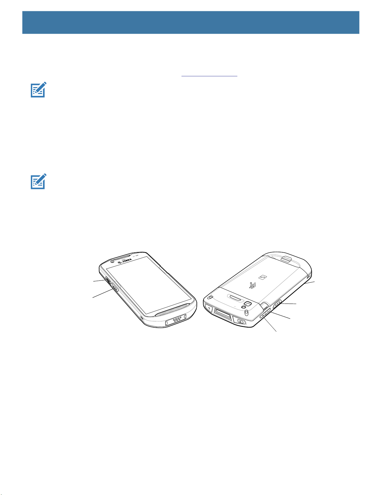
Remapping a Button
Buttons on the device can be programmed to perform different functions or as shortcuts to installed apps. For
a list of key names and descriptions, refer to: techdocs.zebra.com
Settings
.
NOTE:
1. Go to Settings.
2. Touch Key Programmer. A list of programmable buttons displays.
3. Select the button to remap.
4. Touch the BUTTON REMAPPING tab or the SHORTCUT tab that lists the available functions and
5.
NOTE:
screen.
6. Touch the Home button.
It is not recommended to remap the scan button.
applications.
Touch a function or application shortcut to map to the button.
If you select an application shortcut, the application icon appears next to the button on the Key Programmer
Remappable Keys
Figure 5 Key Positions
BUTTON_L2
SCAN
• BUTTON_L2 - PTT button.
• BUTTON_L1 - Programmable button on back of device.
• BUTTON_R1 - Right scan button.
• SCAN - Left scan button.
• VOLUME_DOWN - Volume down button.
• VOLUME_UP - Volume up button.
Keyboards
The device provides multiple keyboard options.
• Android Keyboard - AOSP devices only
• Gboard - GMS devices only
BUTTON_L1
BUTTON_R1
VOLUME_DOWN
VOLUME_UP
38
Page 39

• Enterprise Keyboard
NOTE: By default the Enterprise and Virtual Keyboards are disabled.
Keyboard Configuration
Enabling Keyboards
1. Go to Settings.
2.
Touch System > Languages & input > Virtual keyboard > Manage keyboards.
3. Touch a keyboard to enable.
Switching Between Keyboards
1. To switch between keyboards, touch in a text box to display the current keyboard.
• On the Gboard keyboard, touch and hold (GMS devices only).
• On the Android keyboard, touch and hold (AOSP devices only).
• On the Enterprise keyboard, touch .
Settings
Using the Android and Gboard Keyboards
Use the Android or Gboard keyboards to enter text in a text field.
To configure the keyboard settings, touch and hold
Edit Text
Edit entered text and use menu commands to cut, copy, and paste text within or across apps. Some apps do
not support editing some or all of the text they display; others may offer their own way to select text.
Entering Numbers, Symbols, and Special Characters
1. Enter numbers and symbols.
• Touch and hold one of the top-row keys until a menu appears then select a number or special character.
• Touch the Shift key once for a single capital letter. Touch the Shift key twice to lock in uppercase. Touch
the Shift key a third time to unlock Capslock.
• Touch ?123 to switch to the numbers and symbols keyboard.
• Touch the =\< key on the numbers and symbols keyboard to view additional symbols.
2. Enter special characters.
• Touch and hold a number or symbol key to open a menu of additional symbols. A larger version of the
key displays briefly over the keyboard.
, (comma) and then select Android keyboard settings.
Using the Enterprise Keyboard
The Enterprise Keyboard contains multiple keyboard types.
39
Page 40

Settings
• Numeric
• Alpha
• Special characters
• Data capture.
Numeric Tab
The numeric keyboard is labeled 123. The keys displayed vary on the app being used. For example, an arrow
displays in Contacts, however Done displays in Email account setup.
Alpha Tab
The alpha keyboard is labeled using the language code. For English, the alpha keyboard is labeled EN.
Additional Character Tab
The additional characters keyboard is labeled #*/.
Touch to enter emoji icons in a text message.
Touch ABC to return to the Symbols keyboard.
Scan Tab
The Scan tab provides an easy data capture feature for scanning barcodes.
Language Usage
Use the Language & input settings to change the device’s language, including words added to the dictionary.
Changing the Language Setting
1. Go to Settings.
2. Touch System > Languages & input.
3. Touch Languages. A list of available languages displays.
4. If the desired language is not listed, touch Add a language and select a language from the list.
5. Touch and hold to the right of the desired language, then drag it to the top of the list.
6. The operating system text changes to the selected language.
Adding Words to the Dictionary
1. Go to Settings.
2. Touch System > Languages & input > Advanced > Personal dictionary.
3. If prompted, select the language where this word or phase is stored.
4. Touch + to add a new word or phrase to the dictionary.
40
Page 41

Enter the word or phrase.
5.
6. In the Shortcut text box, enter a shortcut for the word or phrase.
Touch the Home button.
7.
Notifications
Setting App Notifications
To set notification settings for a specific app:
1. Go to Settings.
2. Touch Apps & notifications > SEE ALL XX APPS. The App info screen displays.
3. Select an app.
4. Touch Notifications.
Options vary depending on the app selected.
Settings
5. Select an available option:
Show notifications - Select to turn all notifications from this app on (default) or off.
Touch a notification category to display additional options.
• Alerting - Allow notifications from this app to make sound or vibrate the device.
• Pop on screen - Allow notifications from this app to pop notifications on the screen.
• Silent - Do not allow notifications from this app to make sound or vibrate.
• Minimize - In the Notification panel, collapse notifications to one line.
• Advanced - Touch for additional options.
• Sound - Select a sound to play for notifications from this app.
• Vibrate - Allow notifications from this app to vibrate the device.
• Blink light - Allow notifications from this app the light the Notification LED blue.
• Show notification dot - Allow notifications from this app to add a notification dot to the app icon.
• Override Do Not Disturb - Allow these notifications to interrupt when Do Not Disturb is enabled.
Advanced
• Allow notification dot - Do not allow this app to add a notification dot to the app icon.
• Additional settings in the app - Open the app settings.
Viewing Notification Settings for All Apps
To view the notification settings for all apps:
1. Go to Settings.
2. Touch Apps & Notifications.
3. Scroll down to Notifications to view how many apps have notifications turned off.
4. To set or view notifications settings for a specific app, see Setting App Notifications.
41
Page 42

Settings
Controlling Lock Screen Notifications
To control whether notifications can be seen when the device is locked:
1. Go to Settings.
2. Touch Apps & notifications > Notifications.
3. Touch Notifications on lockscreen and select one of the following:
• Show alerting and silent notifications (default)
• Show alerting notifications only
• Don’t show notifications.
Blink Light
The Notification LED lights blue when an app, such as email and VoIP, generates a programmable notification
or to indicate when the device is connected to a Bluetooth device. By default, LED notifications are enabled.
To change the notification setting:
1. Go to Settings.
2. Touch Apps & notifications > Notifications > Advanced.
3. Touch Blink light to toggle the notification on or off.
42
Page 43
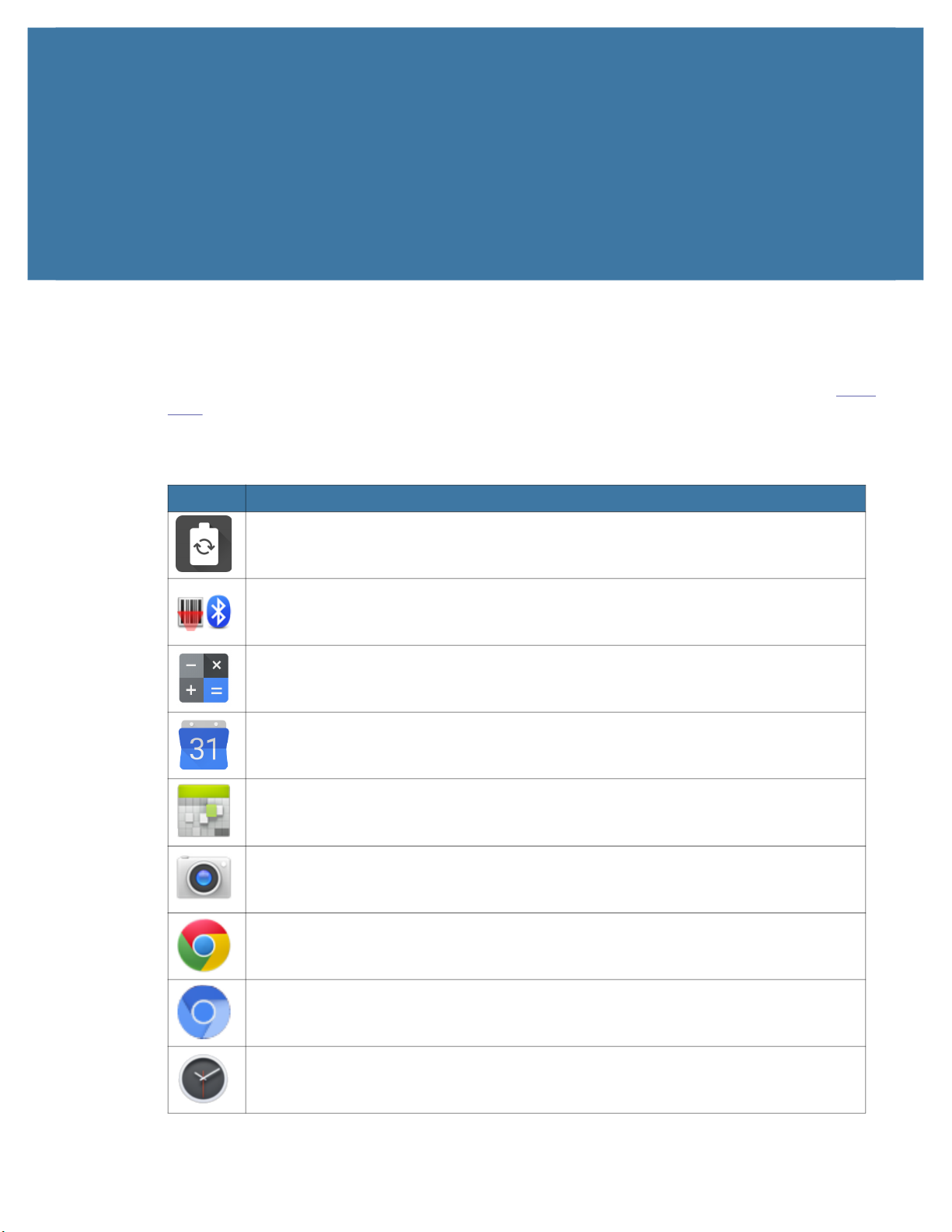
Applications
The APPS screen displays icons for all installed apps. See Application Deployment for information on
installing and uninstalling apps. For information on standard Android apps, go to the Google Play Apps
store.
The following table describes the apps installed on the device.
Table 5 Apps
Icon Description
Battery Manager - Displays battery information, including charge level, status, health
and wear level, and use to place device in Battery Swap mode when replacing the
battery.
Bluetooth Pairing Utility – Use to pair a Zebra Bluetooth scanner with the device by
scanning a barcode.
Calculator - Provides the basic and scientific arithmetic functions.
Calendar - Use to manage events and appointments. GMS/GMS-Restricted only.
Calendar - Use to manage events and appointments. AOSP only.
Camera - Take photos or record videos. For more information, see Camera on page 49.
Chrome - Use to access the Internet or intranet. GMS/GMS-Restricted only.
Chromium - Use to access the Internet or intranet. AOSP only.
Clock - Use to schedule alarms for appointments or as a wake-up.
43
Page 44
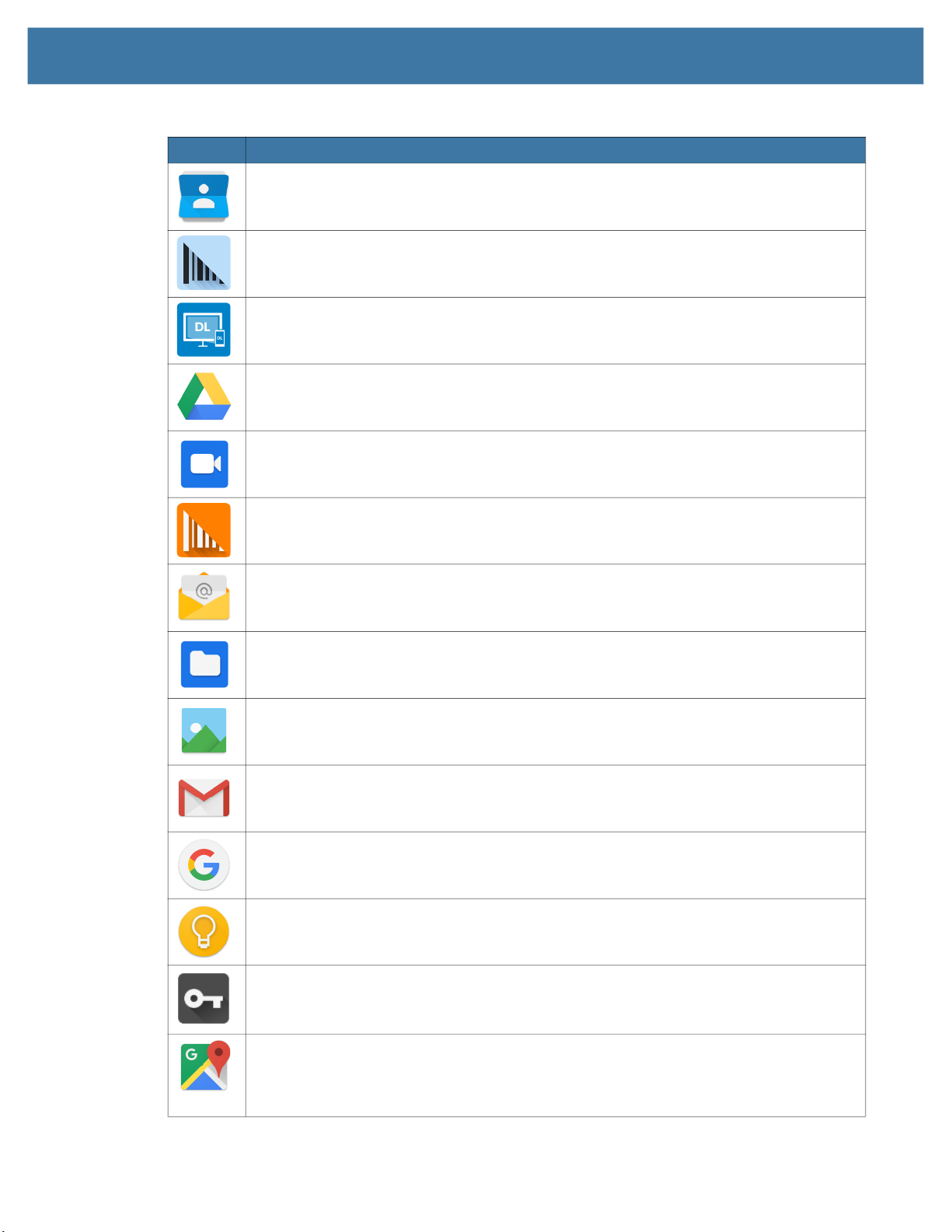
Applications
Table 5 Apps (Continued)
Icon Description
Contacts - Use to manage contact information.
DataWedge - Enables data capture using the imager. For more information, see
DataWedge Demonstration on page 55.
DisplayLink Presenter - Use to present the device screen onto a connected monitor.
Drive - Upload photos, videos, documents, and other files to personal storage site.
GMS/GMS-Restricted only.
Duo - A one-to-one video calling app. GMS/GMS-Restricted only.
DWDemo - Provides a way to demonstrate the data capture features using the imager.
For more information, see DataWedge Demonstration on page 55.
Email - Use to send and receive email. AOSP only.
Files - Organize and manage files on the device.
Gallery - Use to view photos stored on the microSD card. AOSP only.
Gmail - Use to send and receive email using a Google email account.
GMS/GMS-Restricted only.
Google - Launches Google ™ search app. GMS/GMS-Restricted only.
Keep Notes - Use to create, edit, and share notes. GMS/GMS-Restricted only.
License Manager - Use to manage software licenses on the device.
Maps - Use to see your location on a map (with public transit, traffic, or satellite
overlays). Search for any business or place of interest. Provides turn-by-turn navigation
with voice guidance, traffic-avoidance, and alternate routes, for drivers, cyclists, walkers,
and users of public transportation. GMS/GMS-Restricted only.
44
Page 45
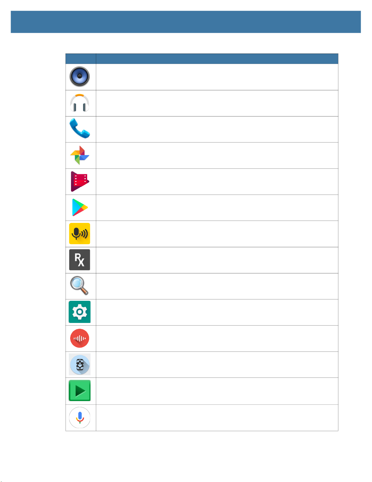
Applications
Table 5 Apps (Continued)
Icon Description
Music - Play music stored on the microSD card or internal storage. AOSP only.
Music - Play music stored on the microSD card or internal storage. AOSP only.
Phone - Use to dial a phone number when used with some Voice over IP (VoIP) clients
(VoIP telephony ready only).
Photos - Use to sync photos with Google account. GMS/GMS-Restricted only.
Play Movies & TV - View movies and video on your device. GMS/GMS-Restricted only.
Play Store - Download music, movies, books, and Android apps and games from the
Google Play Store. GMS/GMS-Restricted only.
PTT Express - Use to launch PTT Express client for VoIP communication.
RxLogger - Use to diagnose device and app issues. For more information, see
RxLogger on page 60.
Search - Use to search the Web. Requires an Internet connection. AOSP only.
Settings - Use to configure the device.
Sound Recorder - Use to record audio. For more information, see Sound Recorder on
page 62.
StageNow - Allows the device to stage a device for initial use by initiating the
deployment of settings, firmware, and software.
Videos - Use to view videos on the device. AOSP only.
Voice Search - Use to perform searches by asking questions. GMS/GMS-Restricted
oniy.
45
Page 46
Applications
Table 5 Apps (Continued)
Icon Description
Worry Free Wifi Analyzer - A diagnostic intelligent app. Use to diagnose surrounding
area and display network stats, such as coverage hole detection, or AP in vicinity. Refer
to the Worry Free Wi-Fi Analyzer Administrator Guide for Android.
Accessing Apps
All apps installed on the device are accessed using the APPS window.
1. On the Home screen, swipe up from the bottom of the screen.
2. Slide the APPS window up or down to view more app icons.
3. Touch an icon to open the app.
YouTube - Use to view videos on the YouTube
YT Music - Use to listen to music. GMS/GMS-Restricted only.
Zebra Bluetooth Settings - Use to configure Bluetooth logging.
Zebra Data Services - Use to enable or disable Zebra Data Services. Some options are
set by the system administrator.
™ web site. GMS/GMS-Restricted only.
Switching Between Recent Apps
Use the Recent button to switch between recently used apps.
1. Touch Recent button.
A window appears on the screen with icons of recently used apps.
2. Slide the apps displayed up and down to view all recently used apps.
3. Swipe left or right to remove app from the list and force close the app.
4. Touch an icon to open an app or touch Back button to return to the current screen.
Battery Manager
The Battery Manager provides detailed information about the battery and battery swap procedures on
supported devices.
Opening Battery Manager
To open the Battery Manager app, swipe up from the bottom of the Home screen, and then touch .
46
Page 47
Battery Manager Information Tab
The Battery Manager displays detailed information about battery charging, health, and status.
Table 6 Battery Icon Description
Battery Icon Description
Battery charge level is between 85% and 100%.
Battery charge level is between 19% and 84%.
Battery charge level is between 0% and 18%.
• Level - The current battery charge level as a percentage. Displays -% when level is unknown.
• Wear - The health of the battery in graphical form. When the wear level exceeds 80%, the bar color
changes to red.
Applications
• Health - The health of the battery. If a critical error occurs, appears. Touch to view the error
description.
• Decommission - The battery is past its useful life and should be replaced. See system
administrator.
• Good - The battery is good.
• Charge error - An error occurred while charging. See system administrator.
• Over Current - An over-current condition occurred. See system administrator.
• Dead - The battery has no charge. Replace the battery.
• Over Voltage - An over-voltage condition occurred. See system administrator.
• Below Temperature - The battery temperature is below the operating temperature. See system
administrator.
• Failure Detected - A failure has been detected in the battery. See system administrator.
• Unknown - See system administrator.
• Charge Status
• Not charging - The device is not connected to AC power.
• Charging-AC - The device is connected to AC power and charging.
• Charging-USB - The device is connected to a host computer with a USB cable and charging.
• Discharging - The battery is discharging.
• Full - That the battery is fully charged.
• Unknown - The battery status is unknown.
• Time until Full - The amount of time until the battery is fully charged.
• Time since charging - The amount of time since the device began charging.
47
Page 48

Applications
• Time until empty - The amount of time until the battery is empty.
• Advanced info - Touch to view additional battery information.
• Battery present status - Indicates that the battery is present.
• Battery level - The battery charge level as a percentage of scale.
• Battery scale - The battery scale level used to determine battery level (100).
• Battery voltage - The current battery voltage in millivolts.
• Battery temperature - The current battery temperature in degrees Centigrade.
• Battery technology - The type of battery.
• Battery current - The average current into or out of the battery over the last second in mAh.
• Battery manufacture date - The date of manufacture.
• Battery serial number - The battery serial number. The number matches the serial number printed
on the battery label.
• Battery part number - The battery part number.
• Battery rated capacity - Lists the rated capacity of the backup battery in mAh.
• Battery decommission status - Indicates if the battery is past its life span.
• Battery Good - The battery is in good health.
• Decommissioned Battery - The battery is past its useful life and should be replaced.
• Base cumulative charge - Cumulative charge using Zebra charging equipment only.
• Battery present capacity - Maximum amount of charge that could be pulled from the battery under
the present discharge conditions if the battery were fully charged.
• Battery health percentage - With a range from 0 to 100, this is the ratio of “present_capacity” to
“design_capacity” at a discharge rate of “design_capacity”.
• % decommission threshold - The default % decommission threshold for a gifted battery as 80%.
• Battery present charge - Amount of usable charge remaining in the battery at present under the
current discharge conditions.
• Battery total cumulative charge - The total accumulated charge in all chargers.
• Battery time since first use - The time passed since the battery was placed in a Zebra terminal for
the first time.
• Battery error status - The error status of the battery.
• Battery usage number - The health of the battery as a result of charging and discharging. A high
number indicates low battery health.
• Usage decommission threshold - When the Battery usage number is greater than or equal to the
Usage decommission threshold, the battery is past its useful life and should be replaced.
• App version - The application version number.
Battery Manager Swap Tab
The Swap tab also appears when the uses presses the Power button and select Battery Swap.
Use to place the device in Battery Swap mode when replacing the battery. Follow the instructions on the
screen. Touch Proceed with battery swap button.
48
Page 49
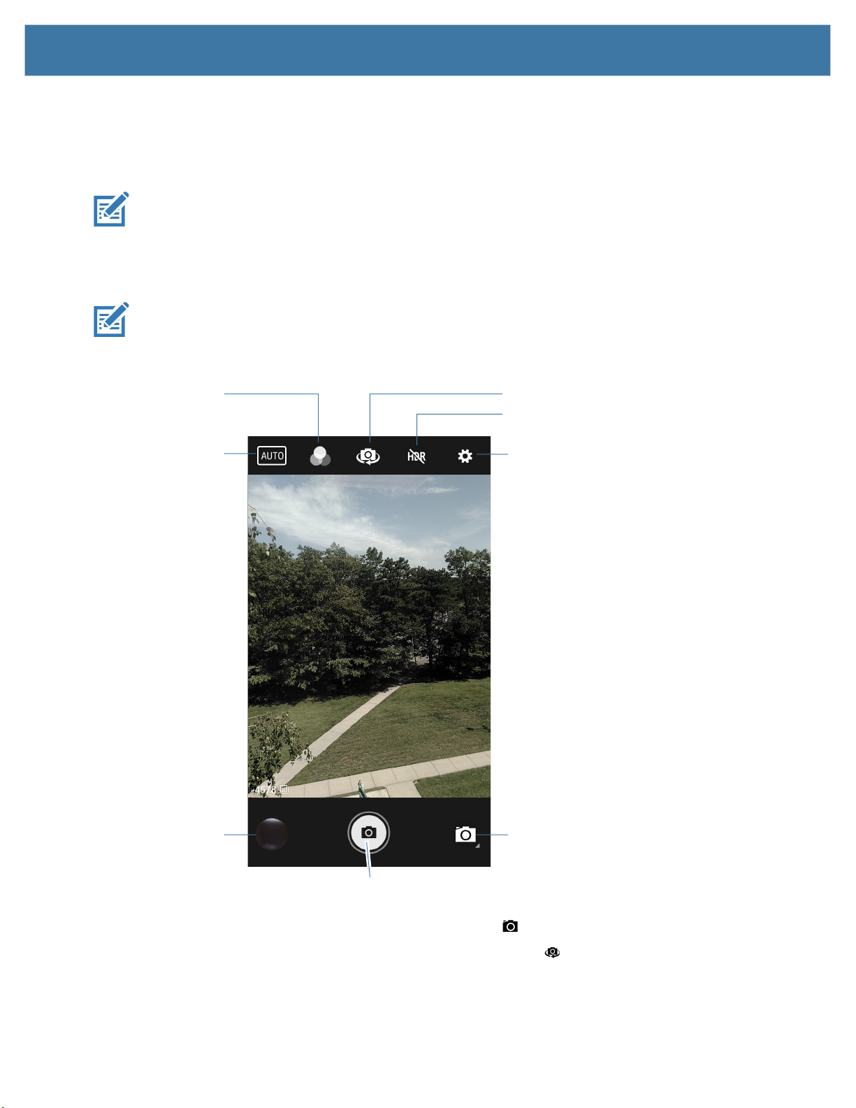
Camera
Taking Photos
Applications
This section provides information for taking photos and recording videos using the integrated digital
cameras.
NOTE: The device saves photos and videos on the microSD card, if installed and the storage path is
changed manually. By default, or if a microSD card is not installed, the device saves photos and videos on
the internal storage.
NOTE: See Photo Settings for camera setting descriptions.
1. Swipe up from the bottom of the Home screen and touch Camera.
Filters
Scene Mode
Camera Switch
HDR
Settings
Gallery
Shutter Button
2. If necessary, touch the Camera Mode icon and touch .
3. To switch between the rear camera and front camera, touch .
4. Frame the subject on the screen.
5. To zoom in or out, press two fingers on the display and pinch or expand fingers. The zoom controls
Camera Mode
appear on the screen.
49
Page 50
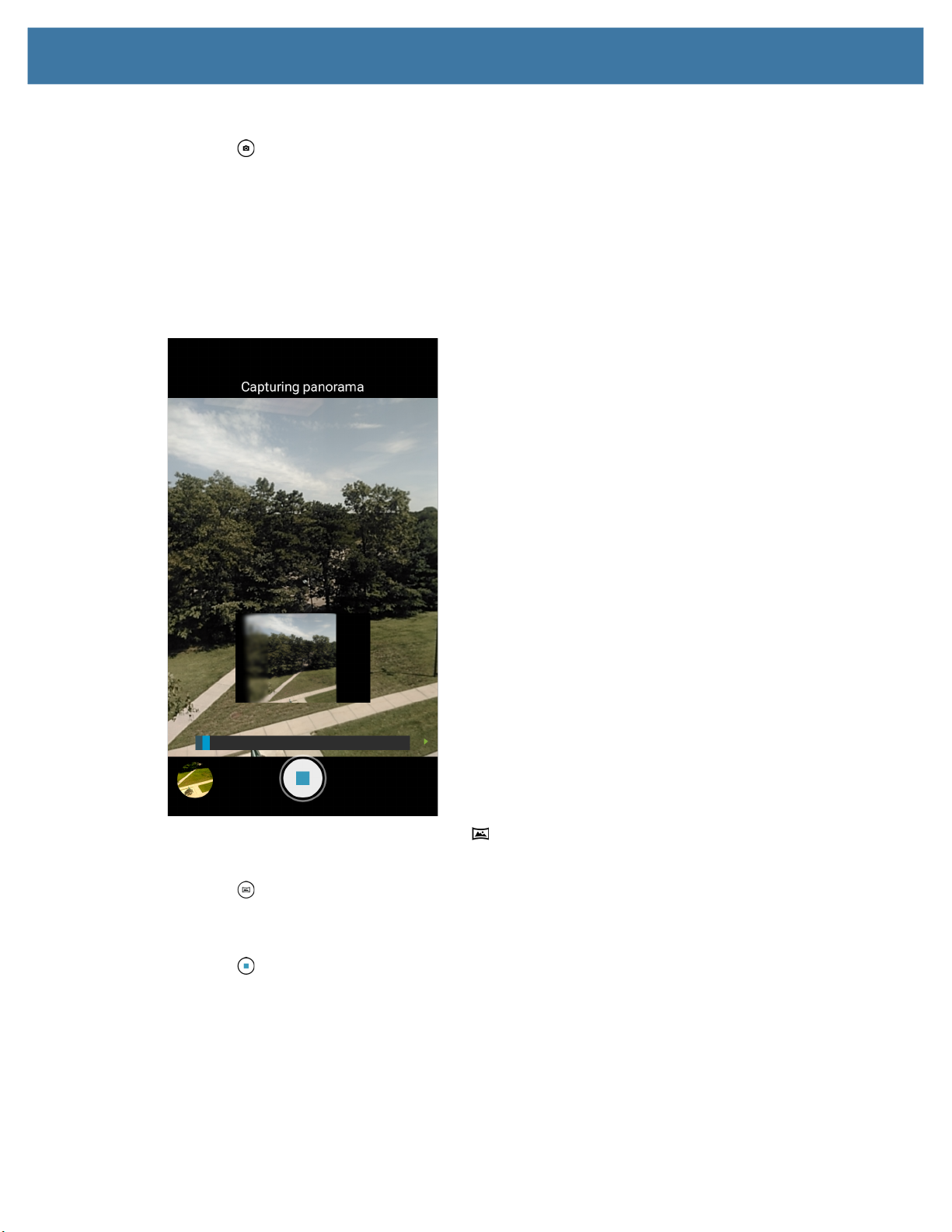
Touch an area on the screen to focus. The focus circle appears. The two bars turn green when in focus.
6.
7. Touch .
The camera takes a photo and a shutter sound plays.
The photo momentarily displays as a thumbnail in the lower left corner.
Taking a Panoramic Photo
Panorama mode creates a single wide image by panning slowly across a scene.
1. Swipe up from the bottom of the Home screen and touch Camera.
Applications
2. Touch the Camera Mode icon and touch .
3. Frame one side of the scene to capture.
4. Touch and slowly pan across the area to capture. A small white square appears inside the button
indicating the capture is in progress.
If you are panning too quickly, the message Too fast appears.
5. Touch to end the shot. The panorama appears immediately and a progress indicator displays while
it saves the image.
Recording Videos
1. Swipe up from the bottom of the Home screen and touch Camera.
50
Page 51
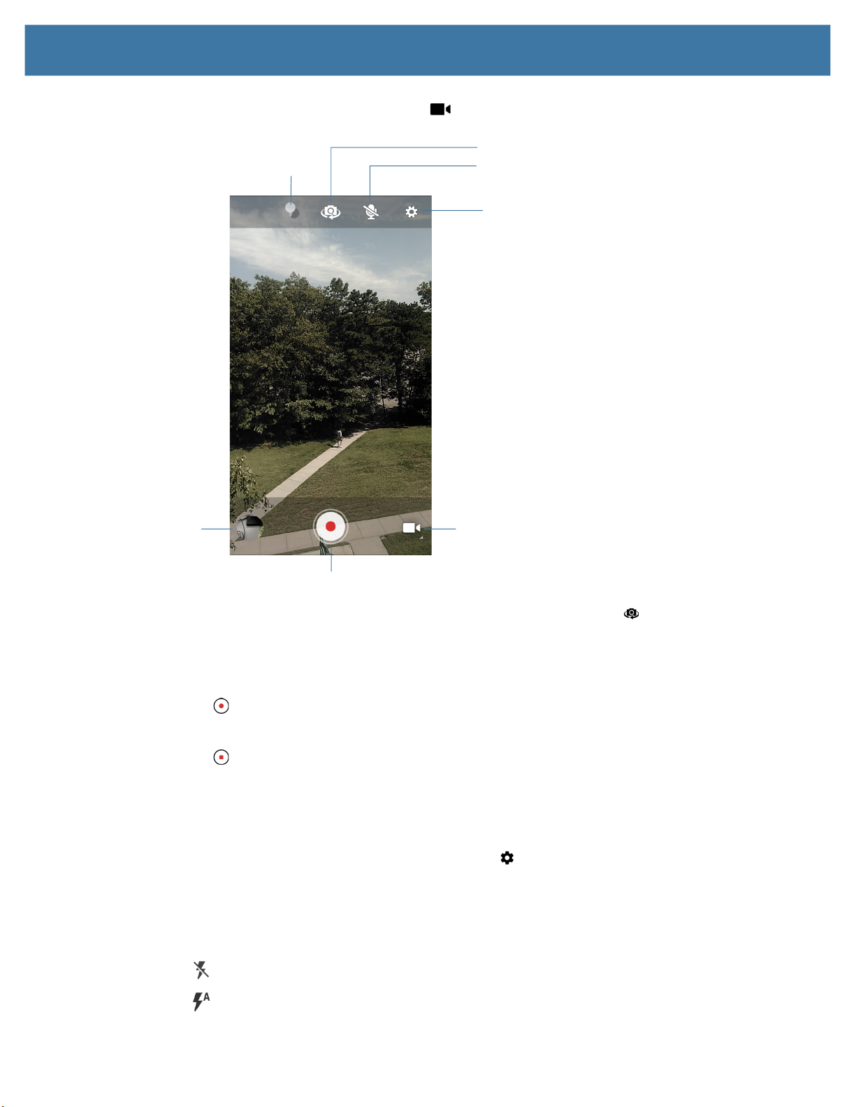
Applications
2.
Touch the camera mode menu and touch .
Color Effect
Camera Switch
Audio
Settings
Gallery
3. To switch between the rear camera and front camera (if available), touch .
4. Point the camera and frame the scene.
5. To zoom in or out, press two fingers on the display and pinch or expand fingers. The zoom controls
appear on the screen.
6. Touch to start recording.
The video time remaining appears in the top left of the screen.
7. Touch to the end recording.
The video momentarily displays as a thumbnail in the lower left corner.
Photo Settings
In Photo mode, photo settings appear on screen. Touch to display the photo settings options.
Rear Camera Photo Settings
• Flash - Select whether the camera relies on its light meter to decide whether a flash is necessary, or to
turn it on or off for all shots.
Camera Mode
Shutter Button
• Off - Disable flash.
• Auto - Adjust flash automatically depending upon light meter (default).
51
Page 52

Applications
• On - Enable flash upon taking a photo.
• Picture size - The size (in pixels) of the photo to: 13M pixels (default), 8M pixels, 5M pixels, 3M
pixels, HD 1080, 2M pixels, HD720, 1M pixels, WVGA, VGA, or QVGA.
• Picture quality - Set the picture quality setting to: Low, Standard or High (default).
• Countdown timer - Select Off (default), 2 seconds, 5 seconds or 10 seconds.
• Storage – Set the location to store the photo to: Phone or SD Card.
• Continuous Shot - Select to take a series of photos quickly while holding the capture button. Off
(default) or On.
• ISO - Set camera sensitivity to light to: Auto (default), ISO Auto (HJR), ISO100, ISO200, ISO400,
ISO800 or ISO1600.
• Exposure - Set the exposure settings to: +2, +1, 0(default), -1 or -2.
• White balance - Select how the camera adjusts colors in different kinds of light, to achieve the most
natural-looking colors:
• Incandescent - Adjust the white balance for incandescent lighting.
• Fluorescent - Adjust the white balance for florescent lighting.
• Auto - Adjust the white balance automatically (default).
• Daylight - Adjust the white balance for daylight.
• Cloudy - Adjust the white balance for a cloudy environment.
• Redeye reduction - Helps eliminate redeye effect. Options: Disabled (default), or Enable.
• ZSL - Set the camera to immediately take a picture when the button is pressed (default – enabled).
• Shutter Sound - Select to play a shutter sound when taking a photo. Options: Disable (default) or
Enable.
• Anti Banding - Allows the camera to avoid problems caused by artificial light sources that are not
constant. These sources cycle (flicker) fast enough to go unnoticed to the human eye, appearing
continuous. The camera’s eye (its sensor) can still see this flicker. Options: Auto (default), 60 Hz, 50
Hz, or Off.
Front Camera Photo Settings
• Selfie Flash - Turns screen white to help produce a little extra light in dimmer settings. Options: Off
(default), or On.
• Picture size - Set the size (in pixels) of the photo to: 5M pixels (default), 3M pixels, HD1080, 2M
pixels, HD720, 1M pixels, WVGA, VGA, or QVGA.
• Picture quality - Set the picture quality setting to: Low, Standard or High (default).
• Countdown timer - Set to: Off (default), 2 seconds, 5 seconds or 10 seconds.
• Storage – Set location to store the photo to: Phone or SD Card.
• Continuous Shot - Select to take a series of photos quickly while holding the capture button. Off
(default) or On.
• Face Detection - Select to turn face detection Off (default) or On.
• ISO - Set how sensitive the camera is to light. Options: Auto (default), ISO Auto (HJR), ISO100,
ISO200, ISO400, ISO800 or ISO1600.
52
Page 53

Applications
• Exposure - Touch to adjust the exposure settings. Options: +2, +1, 0 (default), -1 or -2.
• White balance - Select how the camera adjusts colors in different kinds of light, to achieve the most
natural-looking colors:
• Incandescent - Adjust the white balance for incandescent lighting.
• Fluorescent - Adjust the white balance for florescent lighting.
• Auto - Adjust the white balance automatically (default).
• Daylight - Adjust the white balance for daylight.
• Cloudy - Adjust the white balance for a cloudy environment.
• Redeye reduction - Helps eliminate redeye effect. Options: Disabled (default), or Enable.
• ZSL - Set the camera to immediately take a picture when the button is pressed (default – enabled)
• Selfie Mirror - Select to save a mirror image of the photo. Options: Disable (default), or Enable.
• Shutter Sound - Select to play a shutter sound when taking a photo. Options: Disable (default) or
Enable.
• Anti Banding - Allows the camera to avoid problems caused by artificial light sources that are not
constant. These sources cycle (flicker) fast enough to go unnoticed to the human eye, appearing
continuous. The camera’s eye (its sensor) can still see this flicker. Options: Auto (default), 60 Hz, 50
Hz, or Off.
Video Settings
In Video mode, video settings appear on screen. Touch to display the video settings options.
Rear Camera Video Settings
• Flash - Select whether Rear-facing Camera relies on its light meter to decide whether a flash is
necessary, or to turn it on or off for all shots.
• Off - Disable flash (default).
• On - Enable flash.
• Video quality - Set video quality to: 4k DCI, 4k UHD, HD 1080p (default), HD 720p, SD 480p, VGA,
CIF, or QVGA.
• Video duration - Set to: 30 seconds (MMS), or 30 minutes (default).
• Storage – Set the location to store the photo to: Phone (default) or SD Card.
• White balance - Select how the camera adjusts colors in different kinds of light, to achieve the most
natural-looking colors.
• Incandescent - Adjust the white balance for incandescent lighting.
• Fluorescent - Adjust the white balance for florescent lighting.
• Auto - Adjust the white balance automatically (default).
• Daylight - Adjust the white balance for daylight.
• Cloudy - Adjust the white balance for a cloudy environment.
53
Page 54

• Image Stabilization - Set to reduce blurry videos due to device movement. Options: On or Off
(default).
Front Camera Video Settings
• Video quality - Set video quality to: HD1080 (default), HD 720p (default), HD720, or SD 480p, VGA,
CIF, or QVGA.
• Video duration - Set to: 30 seconds (MMS) or 30 minutes (default).
• Storage – Set the location to store the photo to: Phone (default) or SD Card.
• White balance - Select how the camera adjusts colors in different kinds of light, to achieve the most
natural-looking colors.
• Incandescent - Adjust the white balance for incandescent lighting.
• Fluorescent - Adjust the white balance for florescent lighting.
• Auto - Adjust the white balance automatically (default).
• Daylight - Adjust the white balance for daylight.
Applications
• Cloudy - Adjust the white balance for a cloudy environment.
• Image Stabilization - Set to reduce blurry videos due to device movement. Options: On or Off
(default).
54
Page 55
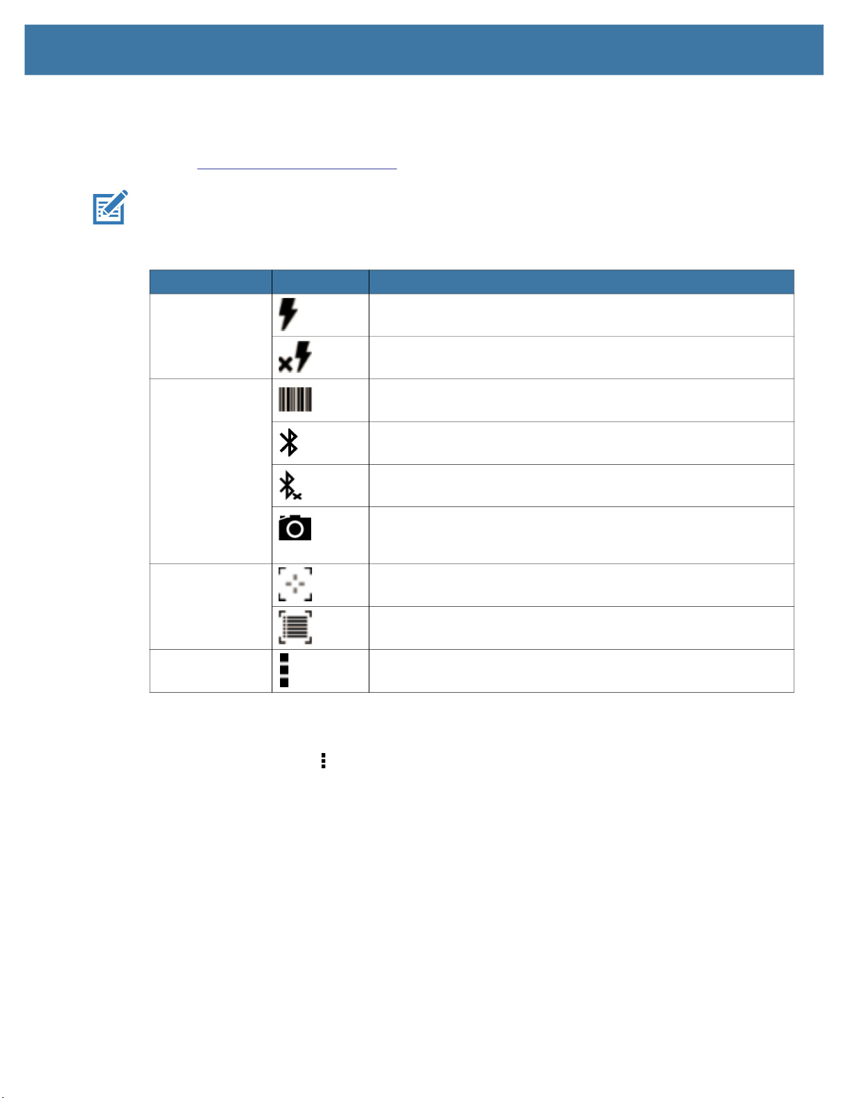
DataWedge Demonstration
Use DataWedge Demonstration to demonstrate data capture functionality. To configure DataWedge,
refer to techdocs.zebra.com/datawedge/
NOTE: DataWedge is disabled on the Home screen. To enable this feature, go to the DataWedge settings
and enable Barcode input option.
Table 7 DataWedge Demonstration Icons
Icon Description
Illumination Imager illumination is on. Touch to turn illumination off.
Data Capture The data capture function is through the internal imager.
Applications
.
Imager illumination is off. Touch to turn illumination on.
A Bluetooth scanner is connected.
Scan Mode Imager is in picklist mode. Touch to change to normal scan mode.
Scanner Selection
To select a scanner, touch > Settings > Scanner selection.
See the Data Capture section for more information.
Press the programmable button or touch the yellow scan button to capture data. The data appears in the
text field below the yellow button.
A Bluetooth scanner is not connected.
The data capture function is through the rear camera. Only
available on MC3300x-S/R devices configured with the camera
option.
Imager is in normal scan mode. Touch to change to picklist mode.
Opens a menu to view the application information or to set the
application DataWedge profile.
55
Page 56
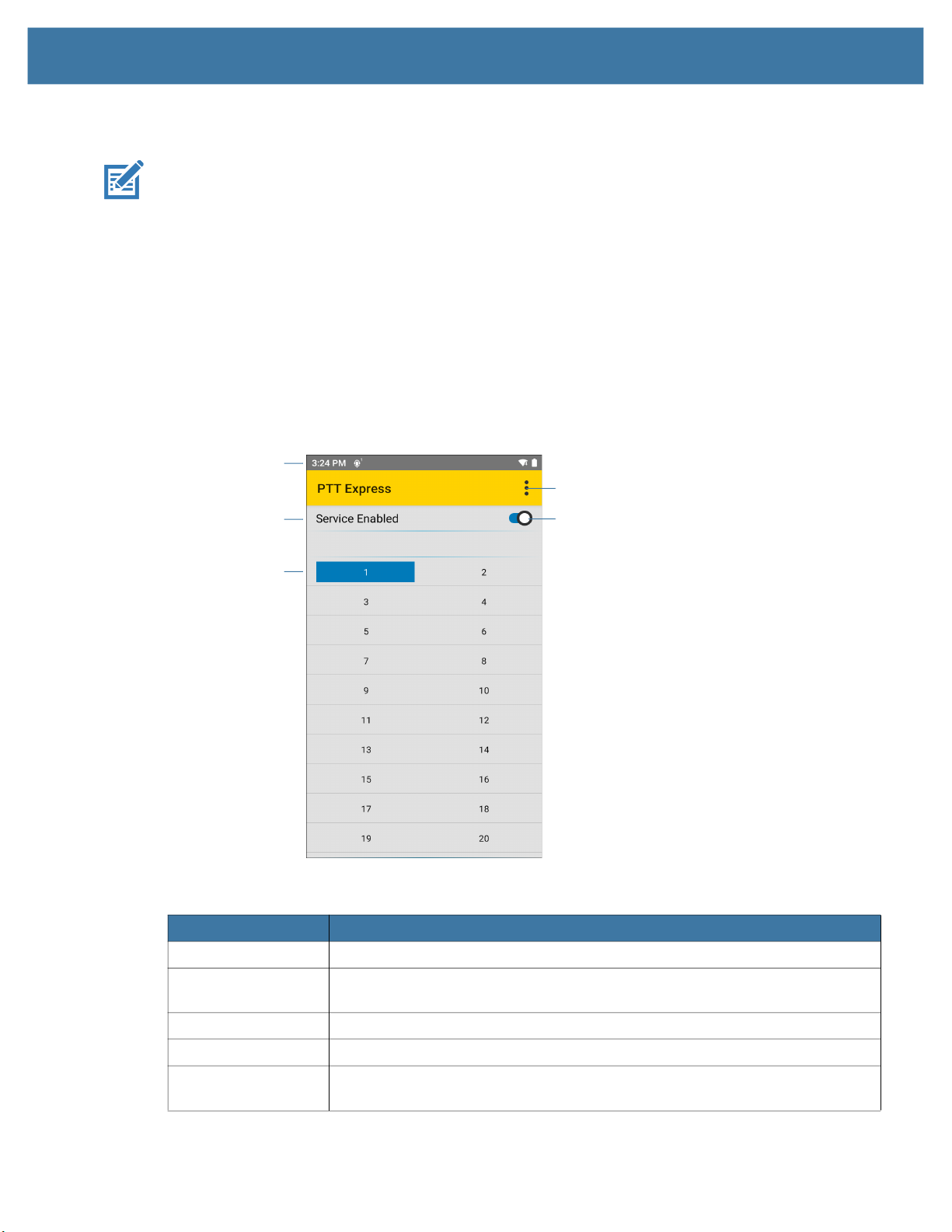
PTT Express Voice Client
NOTE: Requires a PTT Express License.
PTT Express Voice Client enables Push-To-Talk (PTT) communication between disparate enterprise
devices. Leveraging existing Wireless Local Area Network (WLAN) infrastructure, PTT Express delivers
simple PTT communication without requiring a voice communication server.
• Group Call: Press and hold the PTT (Talk) button to start communicating with other voice client users.
• Private Response: Double-press the PTT button to respond to the originator of the last broadcast or to
make a Private Response.
PTT Express User Interface
Figure 6 PTT Express Default User Interface
Notification Icon
Applications
Settings
Service Indication
Talk Group
Table 8 PTT Express Default User Interface Descriptions
Item Description
Notification Icon Indicates the current state of the PTT Express client.
Service Indication Indicates the status of the PTT Express client. Options: Service Enabled,
Service Disabled or Service Unavailable.
Talk Groups Lists all 32 Talk Groups available for PTT communication.
Settings Opens the PTT Express Settings screen.
Enable/Disable
Switch
Turns the PTT service on and off.
Enable/Disable Switch
56
Page 57
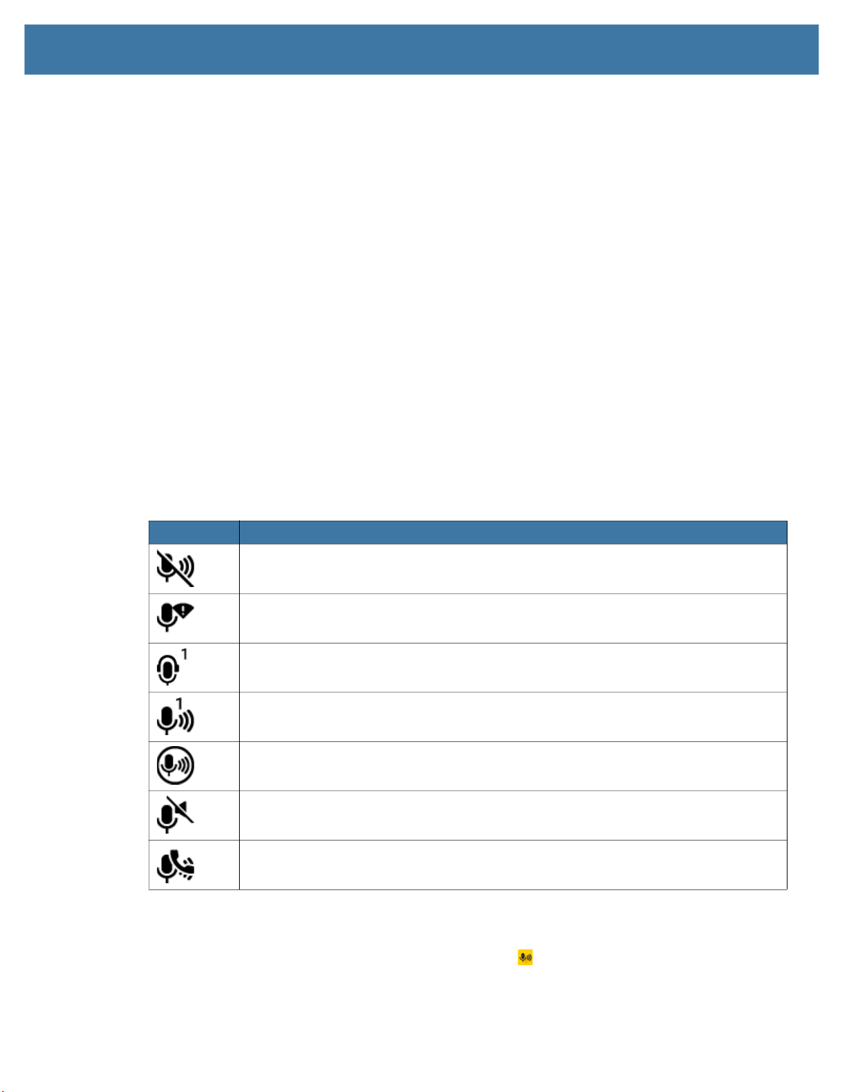
PTT Audible Indicators
The following tones provide helpful cues when using the voice client.
• Talk Tone: Double chirp. Plays when the Talk button is depressed. This is a prompt for you to start
talking.
• Access Tone: Single beep. Plays when another user just finished a broadcast or response. You can
now initiate a Group Broadcast or Private Response.
• Busy Tone: Continuous tone. Plays when the Talk button is depressed and another user is already
communicating on the same talkgroup. Plays after the maximum allowed talk time is reached (60
seconds).
• Network Tone:
• Three increasing pitch beeps. Plays when PTT Express acquires the WLAN connection and the
service is enabled.
• Three decreasing pitch beeps. Plays when PTT Express loses the WLAN connection or the service
is disabled.
PTT Notification Icons
Applications
Notification icons indicate the current state of the PTT Express Voice client.
Table 9 PTT Express Icon Descriptions
Status Icon Description
The PTT Express Voice client is disabled.
The PTT Express Voice client is enabled but not connected to a WLAN.
The PTT Express Voice client is enabled, connected to a WLAN, and listening on the
Talk Group indicated by the number next to the icon.
The PTT Express Voice client is enabled, connected to a WLAN, and communicating on
the Talk Group indicated by the number next to the icon.
The PTT Express Voice client is enabled, connected to a WLAN, and in a private
response.
The PTT Express Voice client is enabled and muted.
The PTT Express Voice client is enabled but it is not able to communicate due to a VoIP
telephony call in progress.
Enabling PTT Communication
1. Swipe up from the bottom of the Home screen and touch .
2. Slide the Enable/Disable Switch to the ON position. The button changes to ON.
57
Page 58
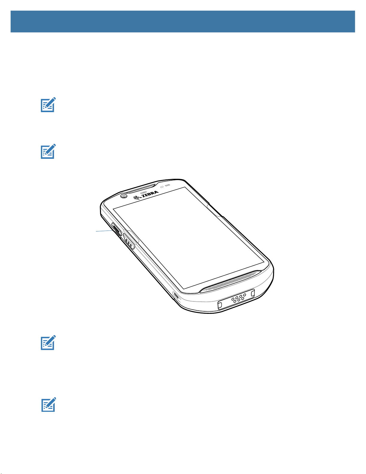
Selecting a Talk Group
One of 32 Talk Groups can be selected by PTT Express users. However, only one talk group may be
enabled at a time on the device. Touch one of the 32 Talk Groups. The selected Talk Group is highlighted.
PTT Communication
This section describes the default PTT Express client configuration. Refer to the PTT Express V1.2 User
Guide for detailed information on using the client.
PTT communication may be established as a Group Call. When PTT Express is enabled, the PTT button
on the left side of the device is assigned for PTT communication. When the Wired Headset is used, Group
Calls can also be initiated using the headset Talk button.
When using a wired headset, use only Zebra wired headsets with a PTT button.
Figure 7 PTT Button
Applications
PTT Button
Creating a Group Call
When using a wired headset, use only Zebra wired headsets with a PTT button.
1. Press and hold the PTT button (or the Talk button on the headset) and listen for the talk tone.
If you hear a busy tone, release the button and wait a moment before making another attempt. Ensure
that PTT Express and the WLAN are enabled.
2. Start talking after hearing the talk tone.
NOTE: Holding the button for more than 60 seconds (default) drops the call, allowing others to make
Group calls. Release the button when finished talking to allow others to make calls.
58
Page 59

Responding with a Private Response
The Private Response can only be initiated once a Group Call has been established. The initial Private
Response is made to the originator of the Group Call.
1. Wait for an access tone.
2. Within 10 seconds, double-press the PTT button, and listen for the talk tone.
3. If you hear a busy tone, release the button and wait a moment before making another attempt. Ensure
that PTT Express and the WLAN are enabled.
4. Start talking after the talk tone plays.
5. Release the button when finished talking.
Disabling PTT Communication
1. Swipe up from the bottom of the Home screen and touch .
2. Slide the Enable/Disable Switch to the OFF position. The button changes to OFF.
3. Touch the Home button.
Applications
59
Page 60

RxLogger
RxLogger is a comprehensive diagnostic tool that provides application and system metrics, allows for the
creation of custom plug-ins, and diagnoses device and application issues. RxLogger logs the following
information: CPU load, memory load, memory snapshots, battery consumption, power states, wireless
logging, cellular logging, TCP dumps, Bluetooth logging, GPS logging, logcat, FTP push/pull, ANR dumps,
etc. All generated logs and files are saved onto flash storage on the device (internal or external).
RxLogger Configuration
RxLogger is built with an extensible plug-in architecture and comes packaged with a number of plug-ins
already built-in. For information on configuring RxLogger, refer to techdocs.zebra.com/rxlogger/
To open the configuration screen, from the RxLogger home screen touch Settings.
Configuration File
RxLogger configuration can be set using an XML file. The config.xml configuration file is located on the
microSD card in the
connection. Edit the configuration file and then replace the XML file on the device. There is no need to stop
and restart the RxLogger service since the file change is automatically detected.
Applications
.
RxLogger\config folder. Copy the file from the device to a host computer using a USB
Enabling Logging
To enable logging:
1. Swipe the screen up and select .
2. Touch Start.
3. Touch the Home button.
Disabling Logging
To disable logging:
1. Swipe the screen up and select .
2. Touch Stop.
3. Touch the Home button.
Extracting Log Files
1. Connect the device to a host computer using an USB connection.
2. Using a file explorer, navigate to the RxLogger folder.
3. Copy the file from the device to the host computer.
4. Disconnect the device from the host computer.
Backing Up
RxLogger Utility allows the user to make a zip file of the RxLogger folder in the device, which by default
contains all the RxLogger logs stored in the device.
60
Page 61

• To save the backup data, touch > BackupNow.
RxLogger Utility
RxLogger Utility is a data monitoring application for viewing logs in the device while RxLogger is running.
Logs and RxLogger Utility features are accessed using Main Chat Head.
Initiating the Main Chat Head
To initiate the Main Chat Head:
1. Open RxLogger.
2. Touch > Toggle Chat Head. The Main Chat Head icon appears on the screen.
3. Touch and drag the Main Chat head icon to move it around the screen.
Removing the Main Chat Head
To remove the Main Chat Head icon:
1. Touch and drag the icon. A circle with an X appears.
Applications
2. Move the icon over the circle and then release.
Viewing Logs
To view logs:
1. Touch the Main Chat Head icon. The RxLogger Utility screen appears.
2. Touch a log to open it. The user can open many logs with each displaying a new sub Chat Head.
3. If necessary, scroll left or right to view additional Sub Chat Head icons.
4. Touch a Sub Chat Head to display the log contents.
Removing a Sub Chat Head Icon
To remove a sub chat Head icon, press and hold the icon until it disappears.
Backing Up In Overlay View
RxLogger Utility allows the user to make a zip file of the RxLogger folder in the device, which by default
contains all the RxLogger logs stored in the device.
The Backup icon is always available in Overlay View.
1. Touch . The Backup dialog box appears.
2. Touch Yes to create the back up.
61
Page 62

Sound Recorder
Use Sound Recorder to record audio messages.
Recordings are saved on the microSD card (if installed) or the internal storage and are available in the
Music application (AOSP devices) or the Play Music application (GMS devices).
Touch to open options menu.
• File type - Select the file type for the recording file.
• AMR
• 3GPP
• AAC
• WAV
• AMR-WB
• AMR-WB-3GPP.
• Storage location - Select the location for the recording file.
• Phone storage
Applications
• SD card
62
Page 63

Data Capture
The device supports data capture using:
• Integrated imager
• Integrated camera
• RS507/RS507x Bluetooth Ring Scanner
• RS5100 Bluetooth Ring Scanner
• RS6000 Bluetooth Ring Scanner
• DS3678 Digital Scanner
• LI3678 Linear Scanner
• DS2278 Digital Scanner
• DS8178 Digital Scanner.
Imaging
The imager uses imaging technology to take a picture of a bar code, stores the resulting image in its
memory, and executes state-of-the-art software decoding algorithms to extract the bar code data from
the image. With a 2D imager, the device has the following features:
• Omnidirectional reading of a variety of bar code symbologies, including the most popular linear,
postal, PDF417, and 2D matrix code types.
• Advanced intuitive laser aiming cross-hair and dot aiming for easy point-and-shoot operation.
Digital Camera
The device with an integrated camera based barcode scanning solution has the following features:
• Omnidirectional reading of a variety of barcode symbologies, including the most popular linear,
postal, QR, PDF417, and 2D matrix code types.
• Cross-hair reticle for easy point-and-shoot operation.
• Picklist mode to decode a particular barcode from many in the field of view.
The solution uses the advanced camera technology to take a digital picture of a barcode, and executes
state-of-the-art software decoding algorithms to extract the data from the image.
63
Page 64

Linear Imager
The device with an integrated linear imager has the following features:
• Reading a variety of bar code symbologies, including the most popular 1-D code types.
• Intuitive aiming for easy point-and-shoot operation.
The imager uses imaging technology to take a picture of a bar code, stores the resulting image in its memory,
and executes state-of-the-art software decoding algorithms to extract the bar code data from the image.
Operational Modes
The device with an integrated imager supports two modes of operation, listed below. Activate each mode by
pressing the Scan button.
• Decode Mode: In this mode, the device attempts to locate and decode enabled barcodes within its field of
view. The imager remains in this mode as long as the user holds the scan button, or until it decodes a
barcode.
NOTE: To enable Pick List Mode, configure in DataWedge or set in an application using a API command.
Data Capture
• Pick List Mode: This mode allows the user to selectively decode a barcode when more than one barcode
is in the device’s field of view. To accomplish this, move the aiming crosshair or dot over the required
barcode to decode only this barcode. This feature is ideal for pick lists containing multiple barcodes and
manufacturing or transport labels containing more than one barcode type (either 1D or 2D).
NOTE: To enable Basic MultiBarcode Mode, configure in DataWedge or set in an application using a API
command.
• Basic MultiBarcode Mode: In this mode, the device attempts to locate and decode a specific number of
unique barcodes within its field of view. The device remains in this mode as long as the user holds the scan
button, or until it decodes all the barcodes.
• The device attempts to scan the programmed number of unique barcodes (from 2 through 100).
• If there are duplicate barcodes (same symbology type and data), only one of the duplicate barcodes is
decoded and the remainder are ignored. If the label has two duplicate barcodes plus another two
different barcodes, a maximum of three barcodes will be decoded from that label; one will be ignored as
a duplicate.
• Barcodes can be of multiple symbology types and still be acquired together. For example, if the
specified quantity for a Basic MultiBarcode scan is four, two barcodes can be symbology type Code 128
and the other two can be symbology type Code 39.
• If the specified number of unique barcodes is not initially in view of the device, the device will not decode
any data until the device is moved to capture the additional barcode(s) or time out occurs. If the device
field of view contains a number of barcodes greater than the specified quantity, the device randomly
decodes barcode(s) until the specified number of unique barcodes is reached. For example, if the count
is set to two and eight barcodes are in the field of view, the device decodes the first two unique barcodes
it sees, returning the data in random order.
• Basic MultiBarcode Mode does not support concatenated barcodes.
64
Page 65
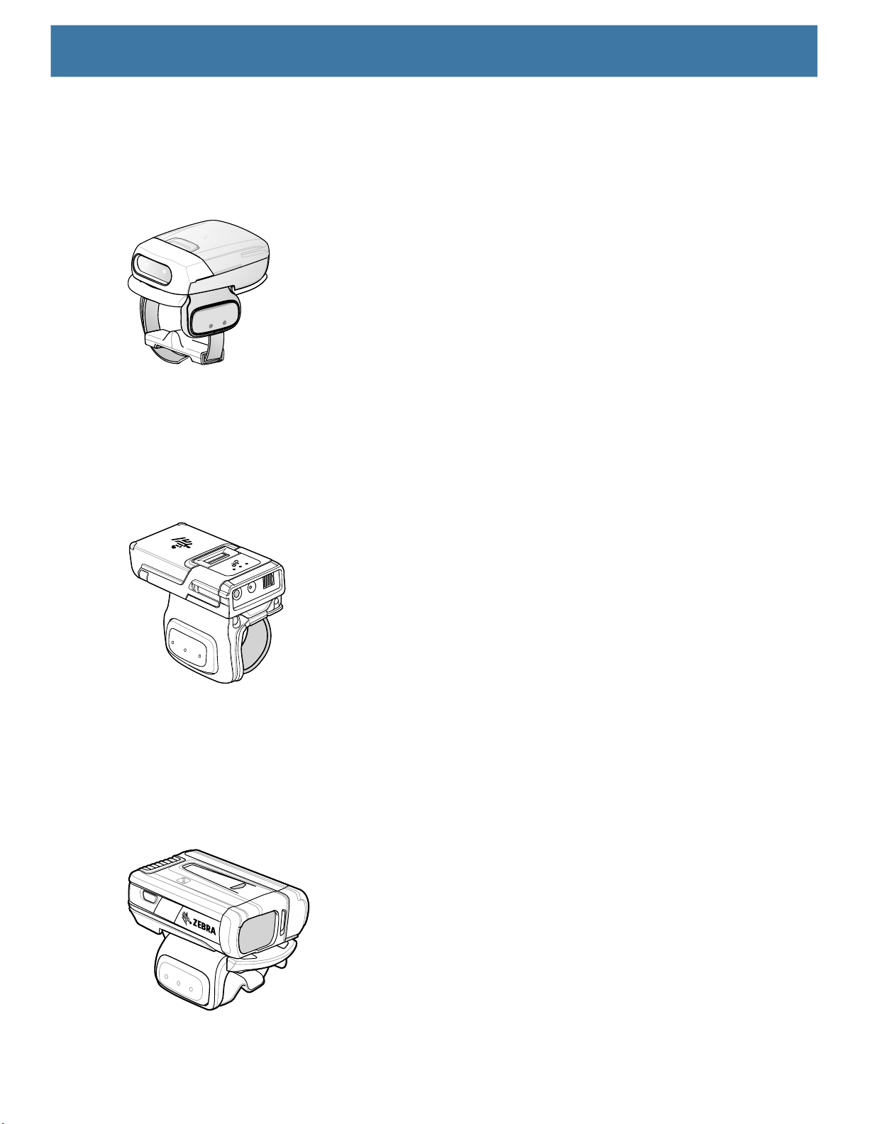
Data Capture
RS507/RS507X Hands-Free Imager
The RS507/RS507X Hands-free Imager is a wearable barcode scan solution for both 1D and 2D barcode
symbologies.
Figure 8 RS507/RS507X Hands-Free Imager
Refer to the RS507/RS507X Hands-free Imager Product Reference Guide for more information.
RS5100 Ring Scanner
The RS5100 Ring Scanner is a wearable barcode scan solution for both 1D and 2D bar code symbologies.
Figure 9 RS5100 Ring Scanner
Refer to the RS5100 Ring Scanner Product Reference Guide for more information.
RS6000 Bluetooth Ring Scanner
The RS6000 Bluetooth Ring Scanner is a wearable bar code scan solution for both 1D and 2D bar code
symbologies.
Figure 10 RS6000 Bluetooth Ring Scanner
Refer to the RS6000 Bluetooth Ring Scanner Product Reference Guide for more information.
65
Page 66
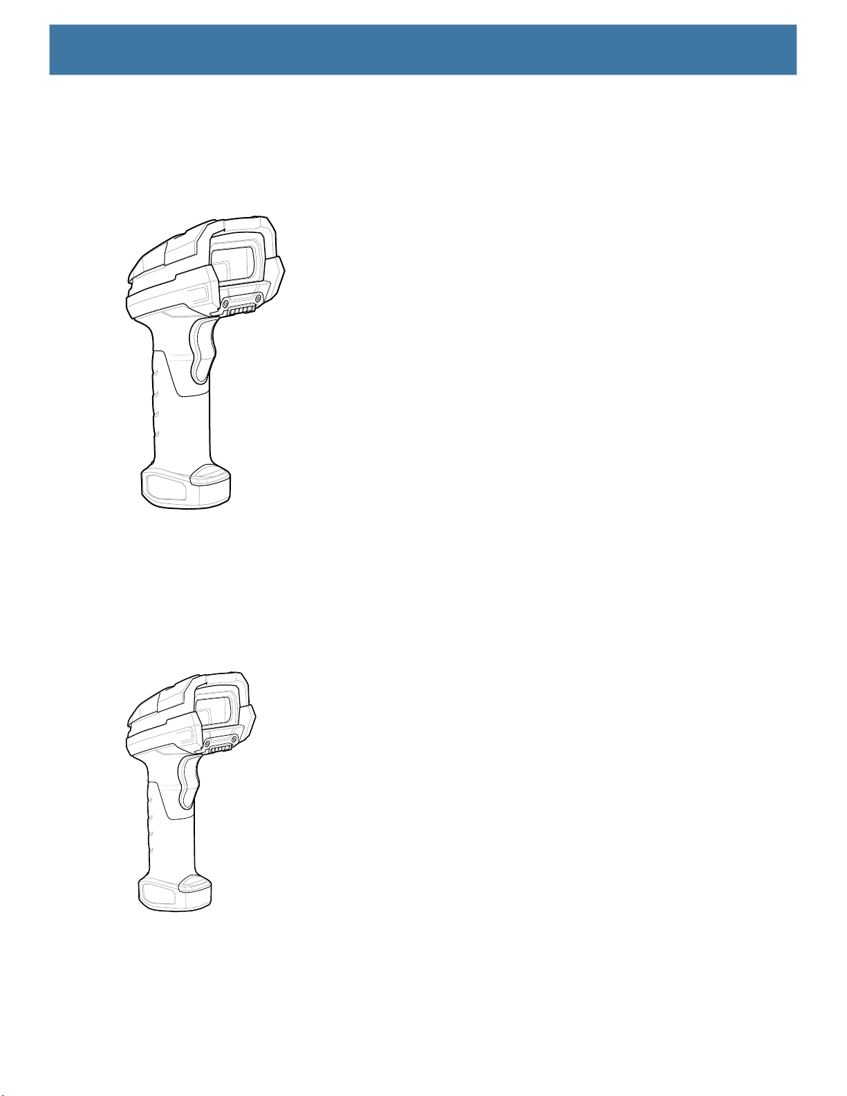
DS3678 Digital Scanner
The cordless DS3678 combines superior 1D and 2D omnidirectional bar code scanning performance and
advanced ergonomics in a lightweight design.
Figure 11 DS3678 Digital Scanner
Data Capture
Refer to the DS36X8 Digital Scanner Product Reference Guide for more information.
LI3678 Linear Scanner
The cordless LI3678 combines excellent scanning performance and advanced ergonomics to provide the best
value in a lightweight scanner, ensuring comfort and ease of use for extended periods of time.
Figure 12 LI3678 Linear Scanner
Refer to the LI36X8 Linear Scanner Product Reference Guide for more information.
66
Page 67
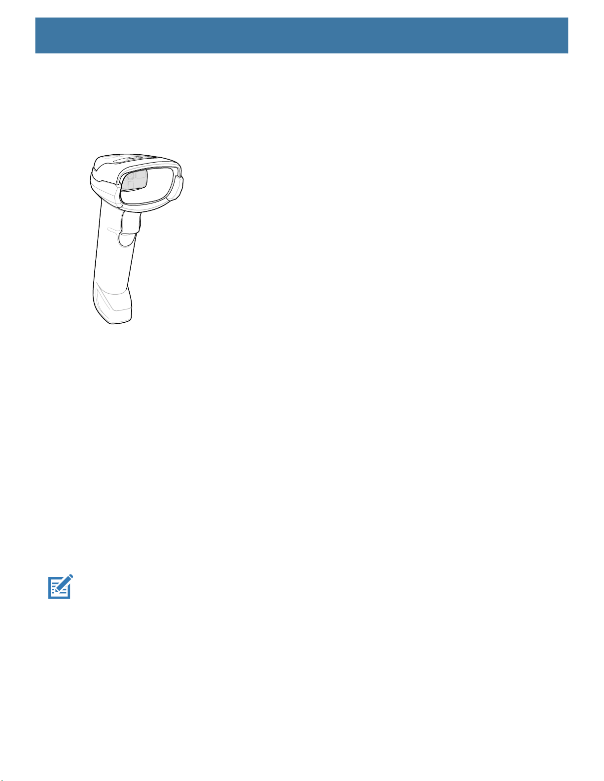
DS2278 Digital Scanner
The DS2278 digital imager scanner scans both 1D and 2D bar codes and does not compromise performance
or features.
Figure 13 DS2278 Digital Scanner
Data Capture
Refer to the DS2278 Digital Scanner Product Reference Guide for more information.
Scanning Considerations
Typically, scanning is a simple matter of aim, scan, and decode, with a few quick trial efforts to master it.
However, consider the following to optimize scanning performance:
• Range: Scanners decode best over a particular working range — minimum and maximum distances from
the barcode. This range varies according to barcode density and scanning device optics. Scan within range
for quick and constant decodes; scanning too close or too far away prevents decodes. Move the scanner
closer and further away to find the right working range for the barcodes being scanned.
• Angle: Scanning angle is important for quick decodes. When the illumination/flash reflects directly back into
the imager, the specular reflection can blind/saturate the imager. To avoid this, scan the barcode so that the
beam does not bounce directly back. Do not scan at too sharp an angle; the scanner needs to collect
scattered reflections from the scan to make a successful decode. Practice quickly shows what tolerances to
work within.
• Hold the device farther away for larger symbols.
• Move the device closer for symbols with bars that are close together.
NOTE: Scanning procedures depend on the app and device configuration. An app may use different scanning
procedures from the one listed above.
Scanning with Internal Imager
To read a barcode, a scan-enabled app is required. The device contains the DataWedge app that allows the
user to enable the imager, decode the barcode data, and display the barcode content.
To scan with the internal imager:
1. Ensure that an app is open on the device and a text field is in focus (text cursor in text field).
2. Point the exit window on the top of the device at a barcode.
67
Page 68
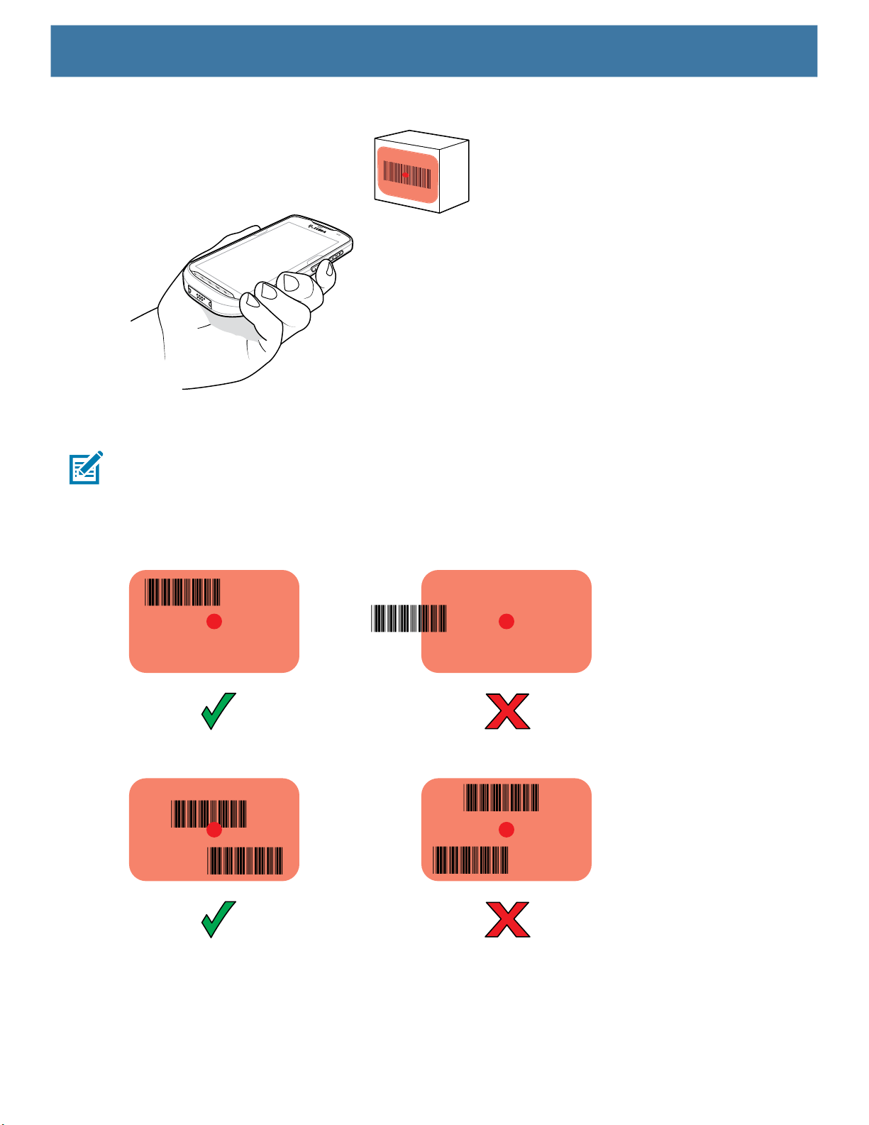
Data Capture
Figure 14 Imager Scanning
3. Press and hold the scan button.
The red laser aiming pattern turns on to assist in aiming.
NOTE: When the device is in Picklist mode, the imager does not decode the barcode until the crosshair or
aiming dot touches the barcode.
4. Ensure the barcode is within the area formed by the crosshairs in the aiming pattern. The aiming dot
increases visibility in bright lighting conditions.
Figure 15 Aiming Pattern
Figure 16 Pick List Mode with Multiple Barcodes
5. The Data Capture LED lights green and a beep sounds, by default, to indicate the barcode was decoded
successfully.
6. Release the scan button.
68
Page 69
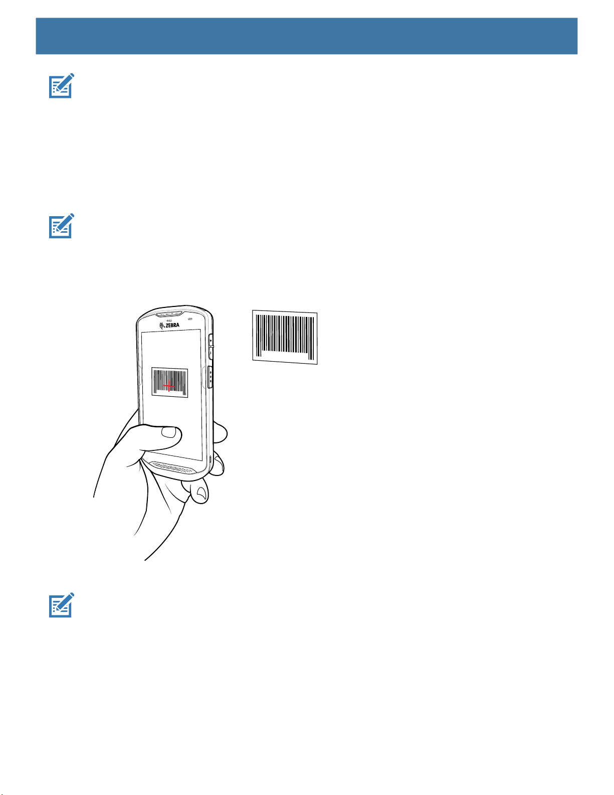
NOTE: Imager decoding usually occurs instantaneously. The device repeats the steps required to take a digital
picture (image) of a poor or difficult barcode as long as the scan button remains pressed.
7. The barcode content data displays in the text field.
Scanning with Internal Camera
To read a barcode, a scan-enabled app is required. The device contains the DataWedge app that allows the
user to enable the imager, decode the barcode data, and display the barcode content.
To scan with the internal camera:
NOTE: When capturing barcode data in poor lighting, turn on Illumination mode in the DataWedge application.
1. Ensure that an app is open on the device and a text field is in focus (text cursor in text field).
2. Point the camera exit window on the back of the device at a barcode.
Figure 17 Camera Scanning
Data Capture
3. Press and hold the scan button. By default, a preview window appears on the screen.
NOTE: When Picklist mode is enabled, move the device until the bar code is centered under the red target on
the screen.
4. Move the device until the barcode is visible on the screen.
5. The Decode LED lights green, a beep sounds and the device vibrates, by default, to indicate the bar code
was decoded successfully.
6. The captured data appears in the text field.
69
Page 70
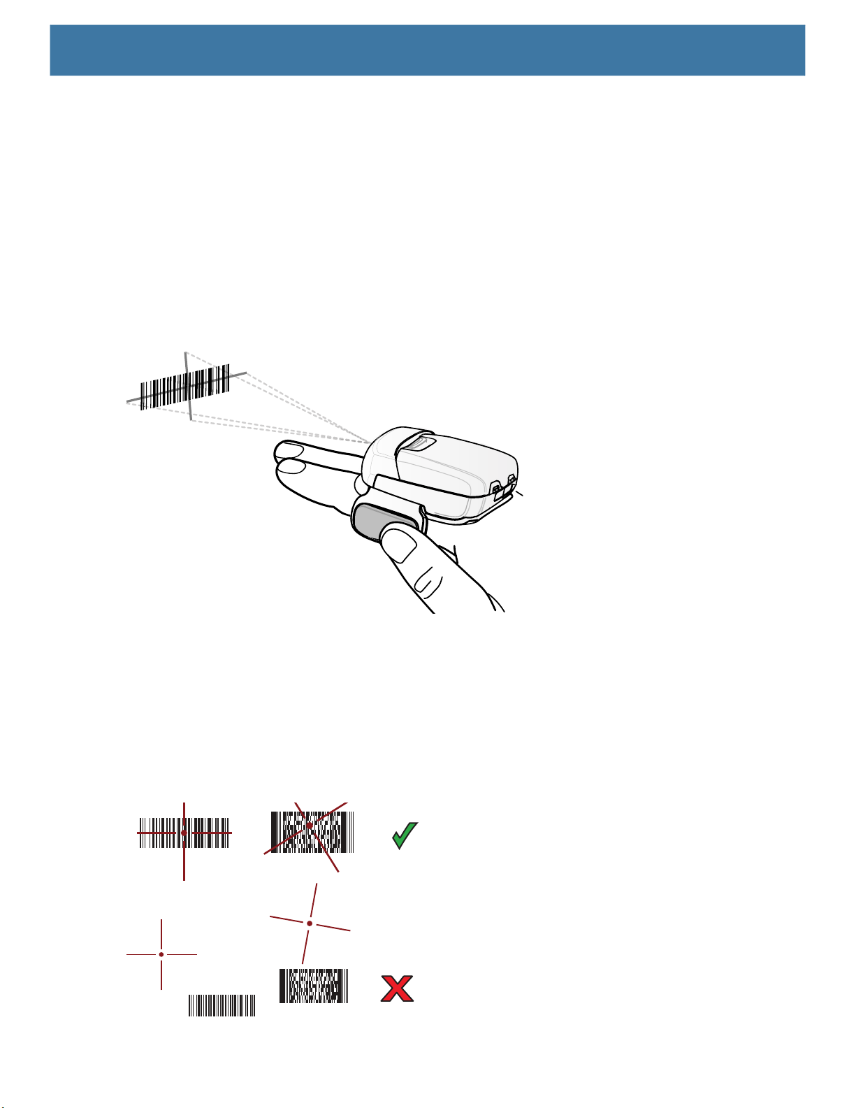
Data Capture
Scanning with RS507/RS507X Hands-Free Imager
To read a barcode, a scan-enabled app is required. The device contains the DataWedge app that allows you to
enable the scanner to decode barcode data and display the barcode content.
To scan with the RS507/RS507X:
1. Pair the RS507/RS507X with the device. See Pairing the Bluetooth Ring Scanner on page 76
information.
2. Ensure that an app is open on the device and a text field is in focus (text cursor in text field).
3. Point the RS507/RS507X at a barcode.
Figure 18 Barcode Scanning with RS507/RS507X
for more
4. Press and hold the trigger.
The red laser aiming pattern turns on to assist in aiming. Ensure the barcode is within the area formed by
the cross-hairs in the aiming pattern. The aiming dot increases visibility in bright lighting conditions.
The RS507/RS507X LEDs light green and a beep sounds to indicate the barcode was decoded
successfully. When the RS507/RS507X is in Pick List mode, the RS507/RS507X does not decode the
barcode until the center of the crosshair touches the barcode.
Figure 19 RS507/RS507X Aiming Pattern
70
Page 71
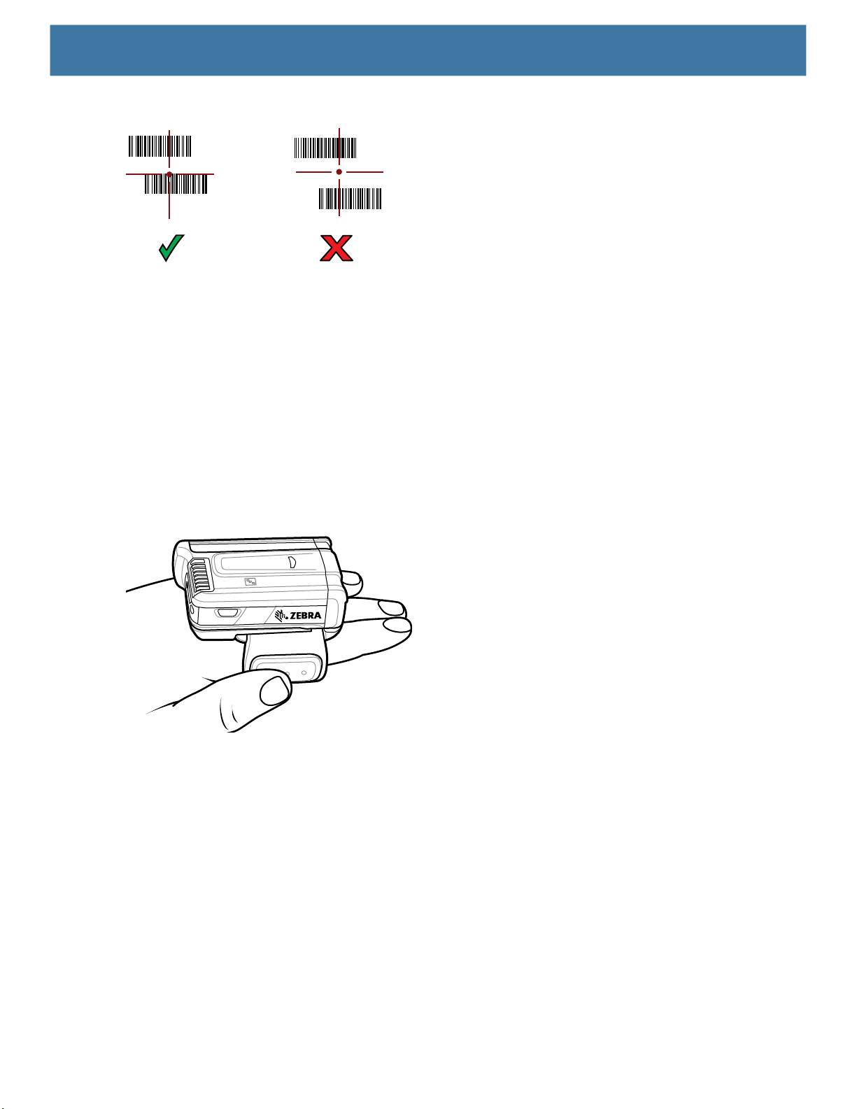
Data Capture
Figure 20 RS507/RS507X Pick List Mode with Multiple Barcodes in Aiming Pattern
5. The captured data appears in the text field.
Scanning with RS6000 Bluetooth Ring Scanner
To read a barcode, a scan-enabled app is required. Devices that contain the Zebra DataWedge app allows you
to enable the scanner to decode barcode data and display the barcode content.
To scan with the RS6000:
1. Pair the RS6000 with the device. See Pairing the Bluetooth Ring Scanner on page 76
2. Ensure that an app is open on the device and a text field is in focus (text cursor in text field).
3. Point the RS6000 at a barcode.
Figure 21 Barcode Scanning with RS6000
4. Press and hold the trigger.
The red laser aiming pattern turns on to assist in aiming. Ensure the barcode is within the area formed by
the cross-hairs in the aiming pattern. The aiming dot increases visibility in bright lighting conditions.
The RS6000 LEDs light green and a beep sounds to indicate the barcode was decoded successfully. When
the RS6000 is in Pick List mode, the RS6000 does not decode the barcode until the center of the crosshair
touches the barcode.
for more information.
71
Page 72
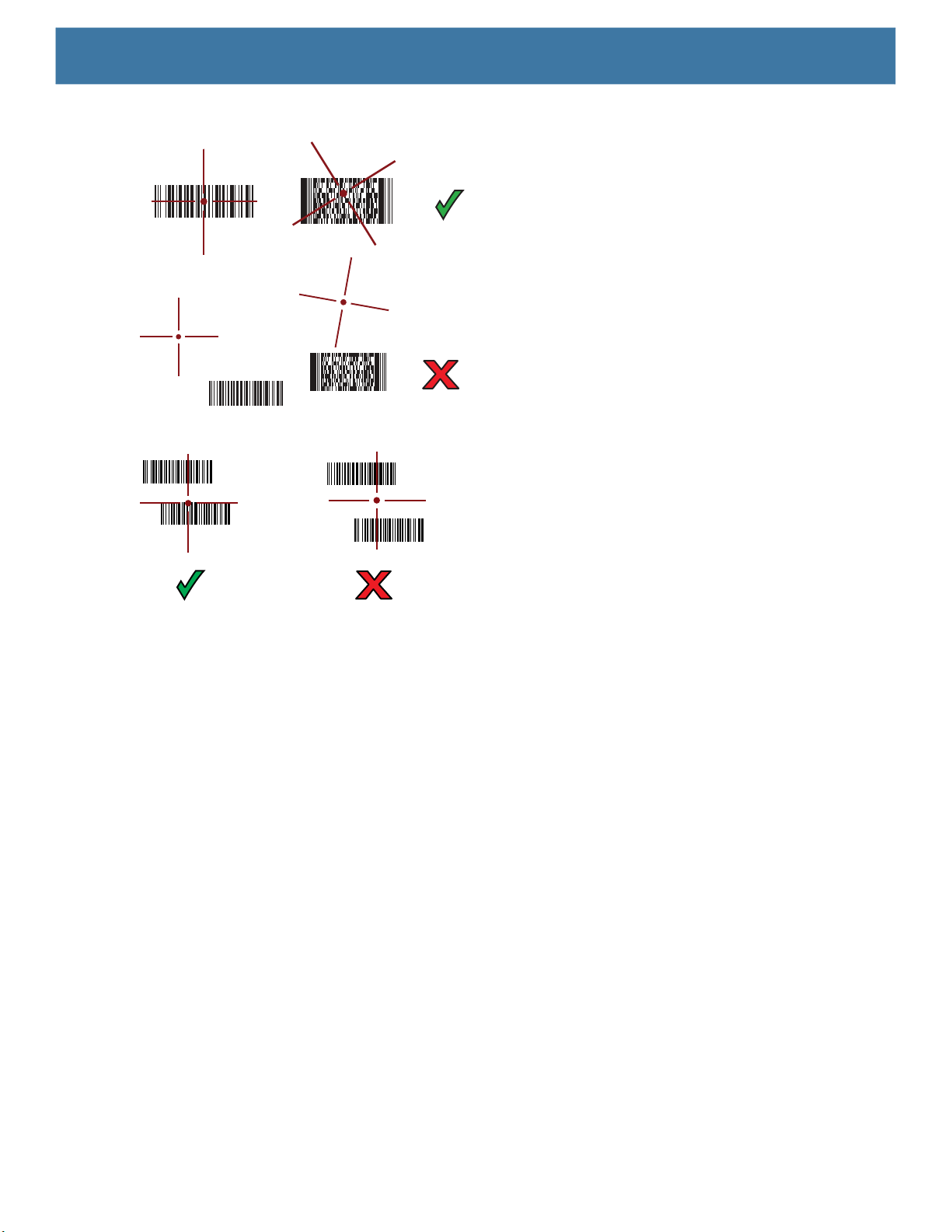
Data Capture
Figure 22 RS6000 Aiming Pattern
Figure 23 RS6000 Pick List Mode with Multiple Barcodes in Aiming Pattern
5. The captured data appears in the text field.
Scanning with RS5100 Ring Scanner
To read a barcode, a scan-enabled app is required. The device contains the DataWedge app that allows you to
enable the scanner to decode barcode data and display the barcode content.
To scan with the RS5100:
1. Pair the RS5100 with the device. See Pairing the Bluetooth Ring Scanner on page 76
2. Ensure that an app is open on the device and a text field is in focus (text cursor in text field).
3. Point the RS5100 at a barcode.
for more information.
72
Page 73
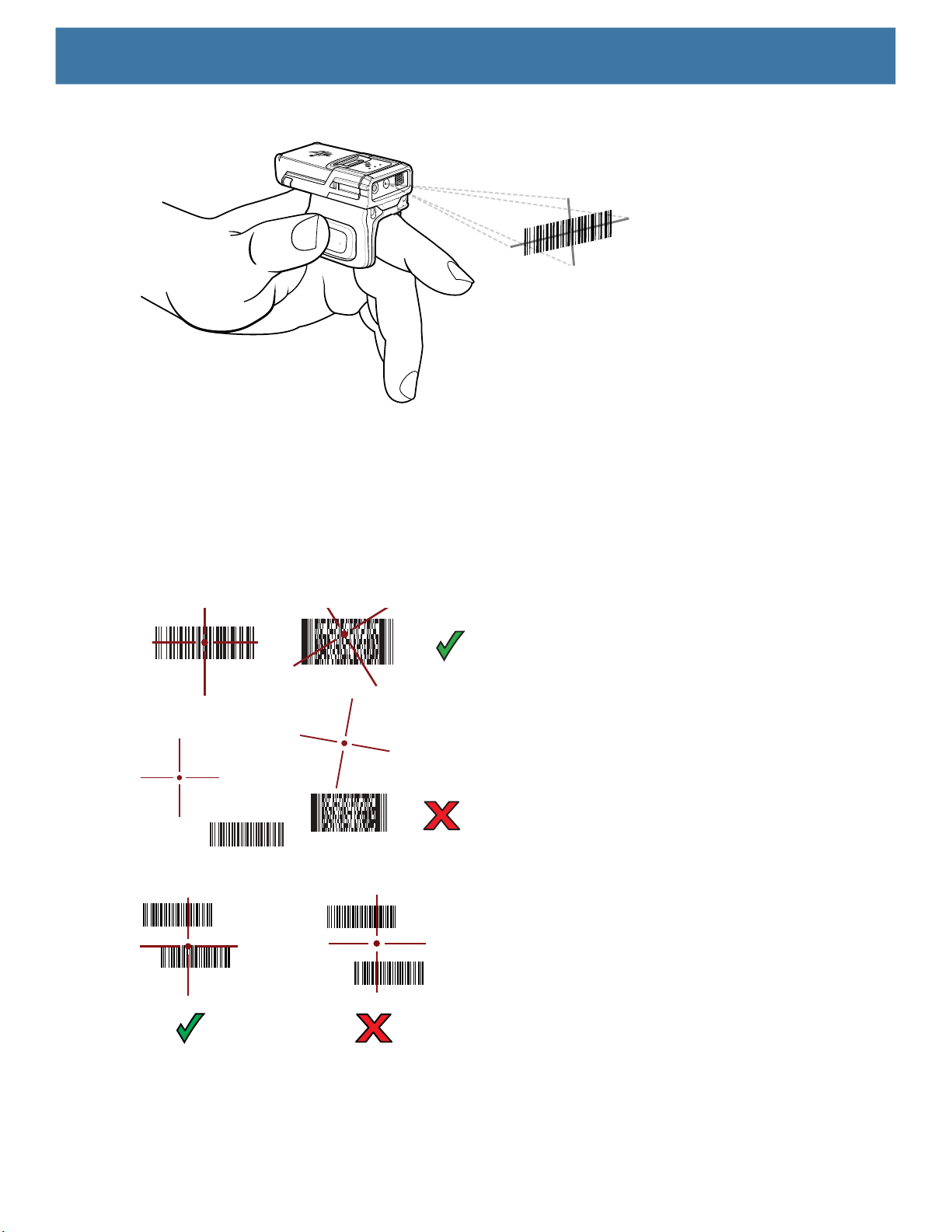
Data Capture
Figure 24 Barcode Scanning with RS5100
4. Press and hold the trigger.
The red laser aiming pattern turns on to assist in aiming. Ensure the barcode is within the area formed by
the cross-hairs in the aiming pattern. The aiming dot increases visibility in bright lighting conditions.
The RS5100 LEDs light green and a beep sounds to indicate the barcode was decoded successfully. When
the RS5100 is in Pick List mode, the RS5100 does not decode the barcode until the center of the crosshair
touches the barcode.
Figure 25 RS5100 Aiming Pattern
Figure 26 RS5100 Pick List Mode with Multiple Barcodes in Aiming Pattern
5. The captured data appears in the text field.
73
Page 74
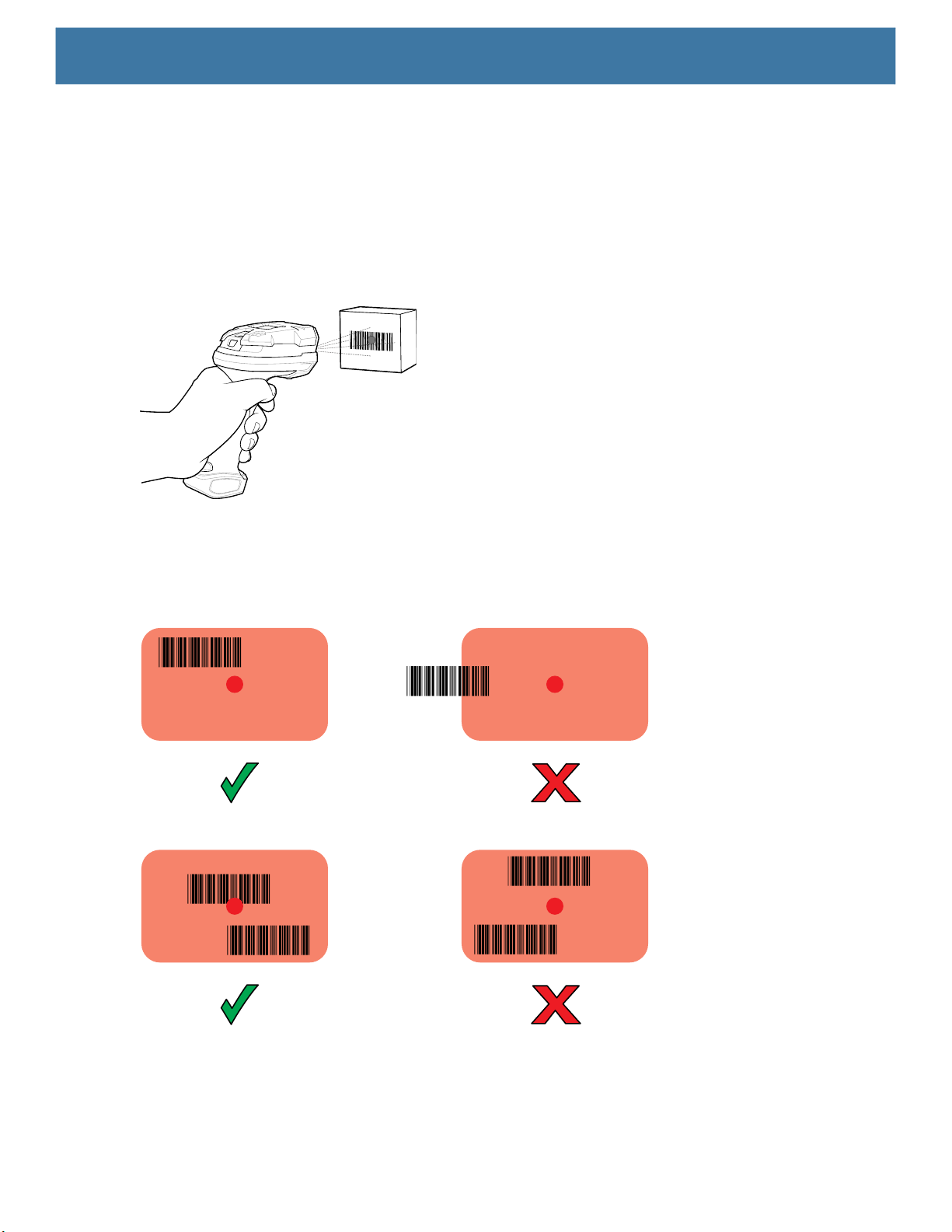
Data Capture
Scanning with the DS3678 Bluetooth Scanner
To scan with the DS3678:
1. Pair the scanner with the device. For more information, see Pairing Bluetooth Scanners.
2. Ensure that an app is open on the device and a text field is in focus (text cursor in text field).
3. Point the scanner at a barcode.
Figure 27 Barcode Scanning (DS3678 shown)
4. Press and hold the trigger.
Ensure the barcode is within the area formed by the aiming pattern. The aiming dot increases visibility in
bright lighting conditions.
Figure 28 DS3678 Aiming Pattern
Figure 29 DS3678 Pick List Mode with Multiple Barcodes in Aiming Pattern
5. The captured data appears in the text field.
Scanning with LI3678 Linear Imager
To scan with the LI3678:
74
Page 75
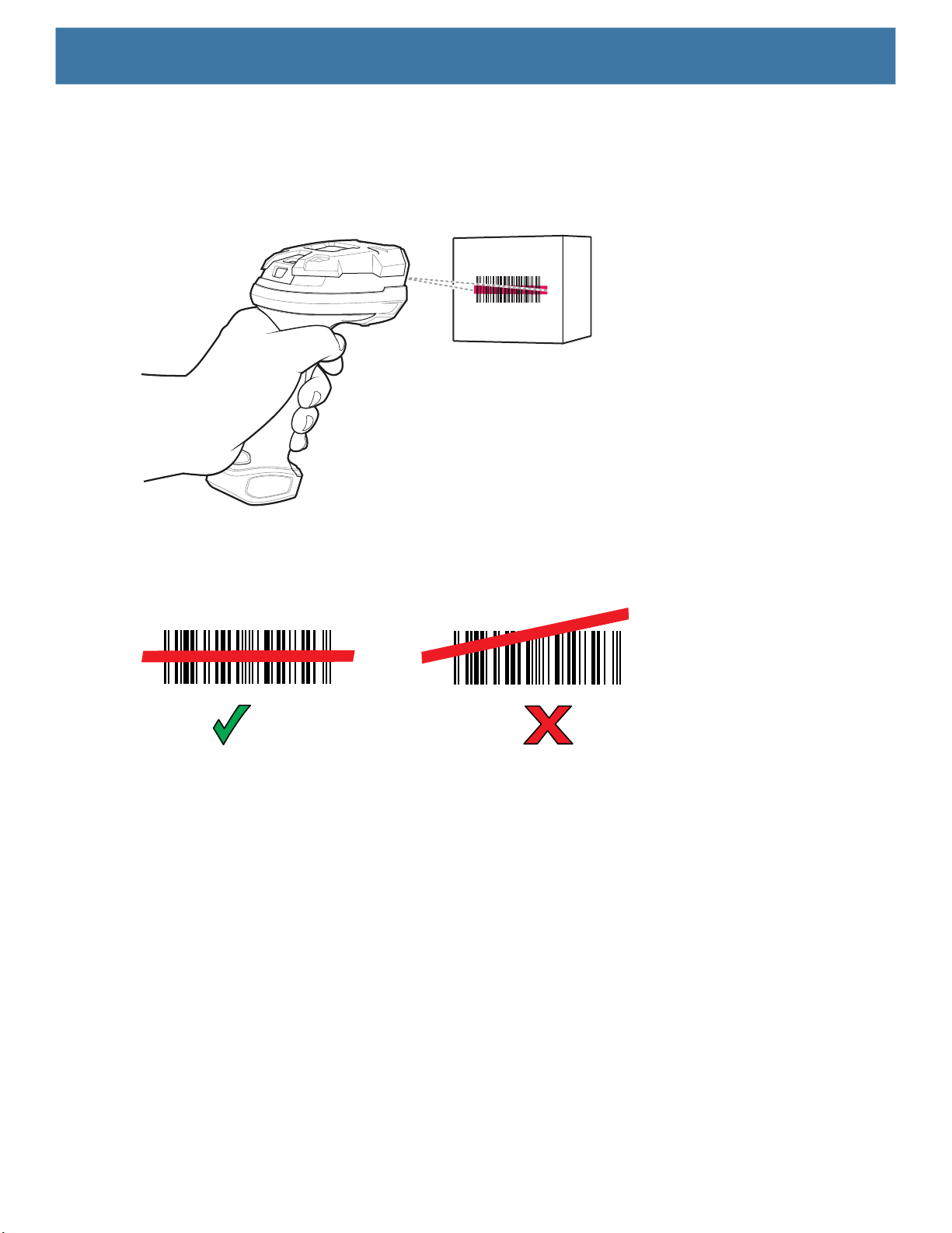
Data Capture
1. Pair the LI3678 with the device. See Pairing a Bluetooth Scanner on page 80 for more information.
2. Ensure that an app is open on the device and a text field is in focus (text cursor in text field).
3. Point the LI3678 at a barcode.
Figure 30 Barcode Scanning with LI3678
4. Press and hold the trigger.
5. Ensure the aiming pattern covers the barcode.
Figure 31 LI3678-SR Aiming Pattern
6. Upon successful decode, the scanner beeps and the LED displays a single green flash.
7. The captured data appears in the text field.
Scanning with DS2278 Digital Scanner
To scan with the DS2278:
1. Pair the DS278 with the device. See Pairing a Bluetooth Scanner on page 80
2. Ensure that an app is open on the device and a text field is in focus (text cursor in text field).
3. Point the scanner at a barcode.
for more information.
75
Page 76

Data Capture
Figure 32 Barcode Scanning with DS2278
4. Press and hold the trigger.
5. Ensure the aiming pattern covers the barcode.
Figure 33 DS2278 Aiming Pattern
6. Upon successful decode, the scanner beeps and the LED flashes, and the scan line turns off.
7. The captured data appears in the text field.
Pairing the Bluetooth Ring Scanner
To connect the Bluetooth Ring Scanner to the device, use one of the following methods:
• Near Field Communication (NFC) (RS5100/RS6000 only)
• Simple Serial Interface (SSI)
• Bluetooth Human Interface Device (HID) Mode.
Pairing Using Near Field Communication
NOTE: RS5100 and RS6000 only.
The device provides the ability to pair the Ring Scanner using NFC.
To pair using NFC:
1. Ensure that the Ring Scanner is in SSI mode. Refer to the RS5100 or RS6000 User Guide for more
information.
2. Ensure that NFC is enabled on the device.
76
Page 77
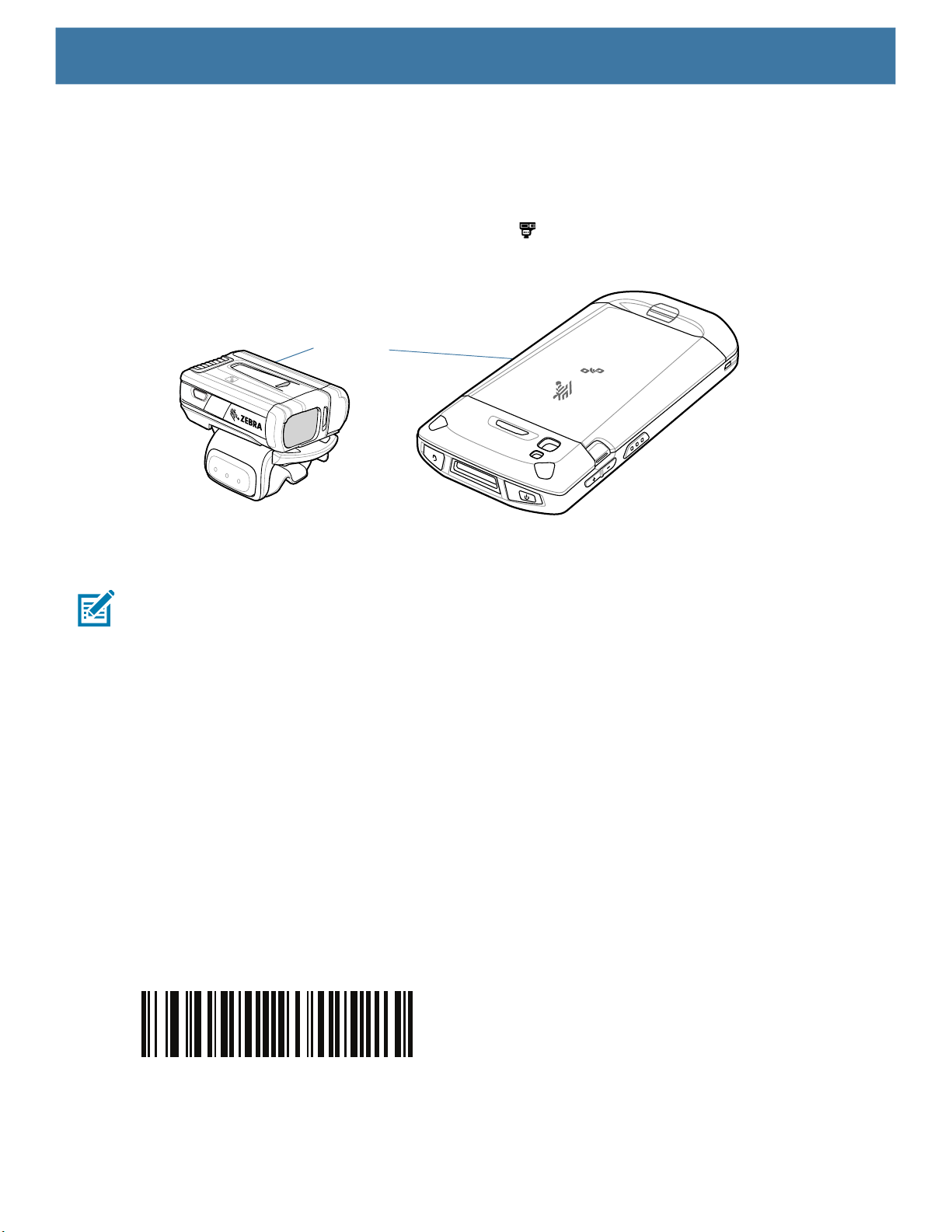
Data Capture
3. Align the NFC icon on the Ring Scanner with the NFC antenna on the device.
The Status LED blinks blue indicating that the Ring Scanner is attempting to establish connection with the
device. When connection is established, the Status LED turns off and the Ring Scanner emits a single
string of low/high beeps.
A notification appears on the device screen and the icon appears in the Status bar.
Figure 34 Align NFC Antennas (RS6000 shown)
NFC Logo
Pairing in HID Mode Using Near Field Communication
NOTE: RS5100 and RS6000 only.
The device provides the ability to pair the Ring Scanner in HID mode using NFC.
To pair in HID mode using NFC:
1. Ensure that NFC is enabled on the device.
2. Ensure that Bluetooth is enabled on the device.
3. Place the Ring Scanner in Human Interface Device (HID) mode. If the Ring Scanner is already in HID
mode, skip to step 4.
a. Remove the battery from the Ring Scanner.
b. Press and hold the Restore key.
c. Install the battery onto the Ring Scanner.
d. Keep holding the Restore key for about five seconds until a chirp is heard and the Scan LEDs flash
green.
e. Scan the barcode below to place the Ring Scanner in HID mode.
Figure 35 Ring Scanner Bluetooth HID Barcode
4. Remove the battery from the Ring Scanner.
5. Re-install the battery into the Ring Scanner.
77
Page 78
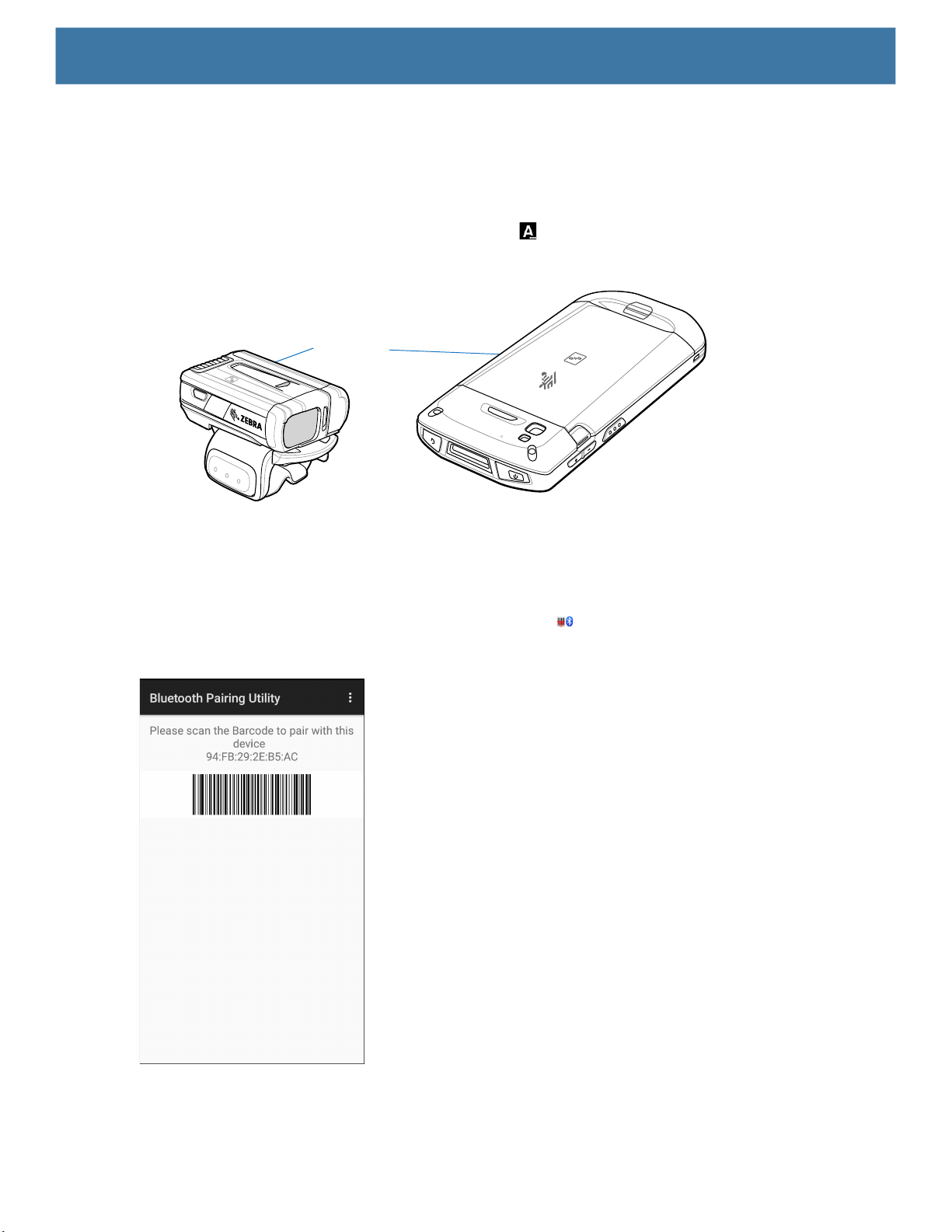
Data Capture
6. Align the NFC icon on the Ring Scanner with the NFC antenna on the device.
The Ring Scanner Status LED blinks blue indicating that the Ring Scanner is attempting to establish
connection with the device. When connection is established, the Status LED turns off and the Ring Scanner
emits a single string of low/high beeps.
A notification appears on the device screen and the icon appears in the Status bar.
Figure 36 Align NFC Antennas (RS6000 shown)
NFC Logo
Pairing Using Simple Serial Interface
To pair the Ring Scanner with the device using SSI.
1. Swipe up from the bottom of the Home screen and touch .
Figure 37 Bluetooth Pairing Utility
78
Page 79
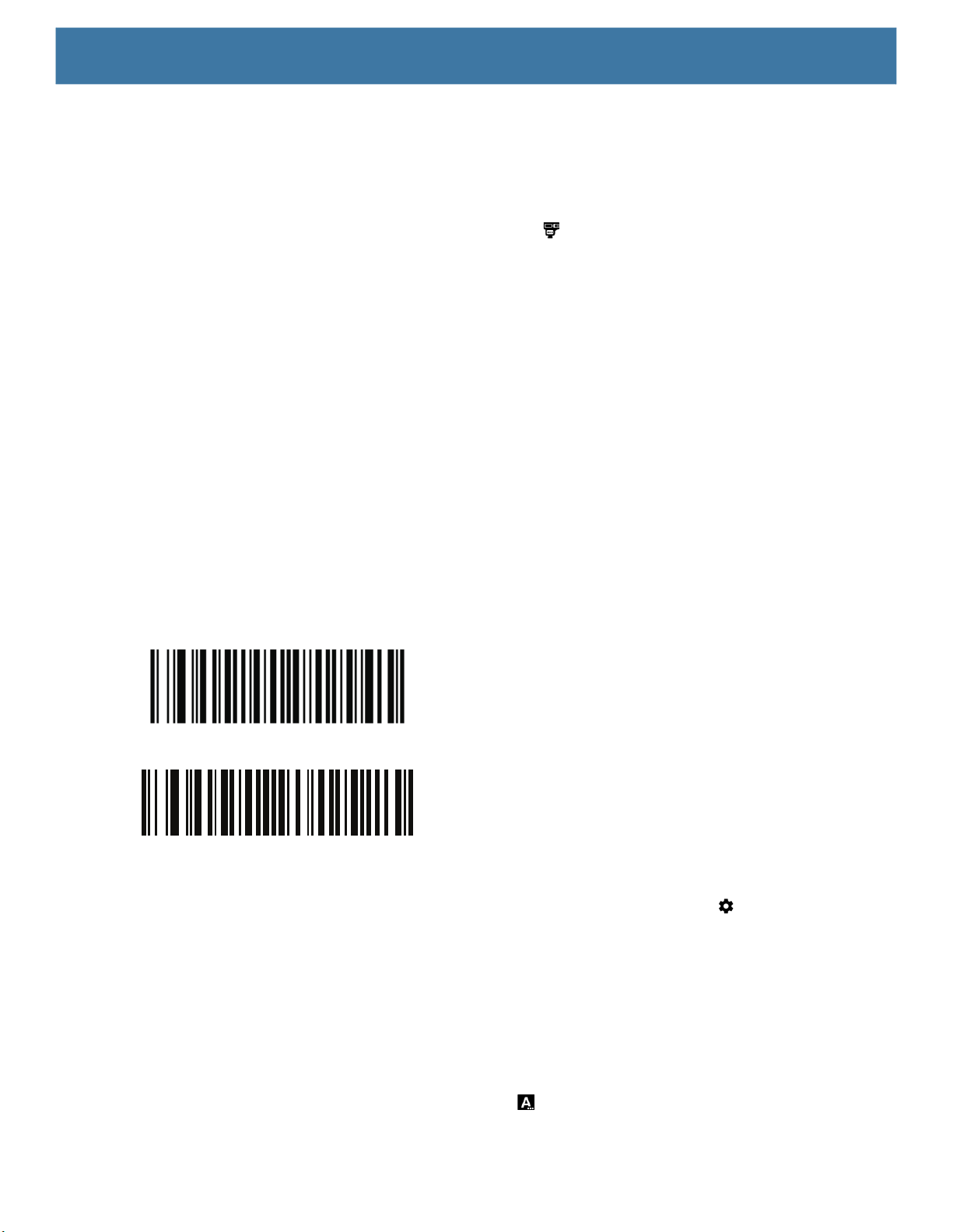
Data Capture
2. Using the Ring Scanner, scan the barcode on the screen.
The Ring Scanner emits a string of high/low/high/low beeps. The Scan LED flashes green indicating that
the Ring Scanner is attempting to establish connection with the device. When connection is established, the
Scan LED turns off and the Ring Scanner emits one string of low/high beeps.
A notification appears on the Notification panel and the icon appears in the Status bar.
Pairing Using Bluetooth Human Interface Device
To pair the Ring Scanner with the device using Human Interface Device (HID):
1. Ensure that Bluetooth is enabled on both devices.
2. Ensure that the Bluetooth device to discover is in discoverable mode.
3. Ensure that the two devices are within 10 meters (32.8 feet) of one another.
4. Place the Ring Scanner in HID mode. If the Ring Scanner is already in HID mode, skip to step 5.
a. Remove the battery from the Ring Scanner.
b. Press and hold the Restore key.
c. Install the battery onto the Ring Scanner.
d. Keep holding the Restore key for about five seconds until a chirp is heard and the Scan LEDs flash
green.
e. Scan the barcode below to place the Ring Scanner in HID mode.
Figure 38 RS507/RS507x Ring Scanner Bluetooth HID Barcode
Figure 39 RS5100 / RS6000 Ring Scanner Bluetooth HID Barcode
5. Remove the battery from the Ring Scanner.
6. Re-install the battery into the Ring Scanner.
7. Swipe down from the Status bar to open the Quick Access panel and then touch .
8. Touch Bluetooth.
9. Touch Pair new device. The device begins searching for discoverable Bluetooth devices in the area and
displays them under Available devices.
10.Scroll through the list and select Ring Scanner.
The device connects to the Ring Scanner and Connected appears below the device name. The Bluetooth
device is added to the Paired devices list and a trusted (“paired”) connection is established.
A notification appears on Notification panel and the icon appears in the Status bar.
79
Page 80
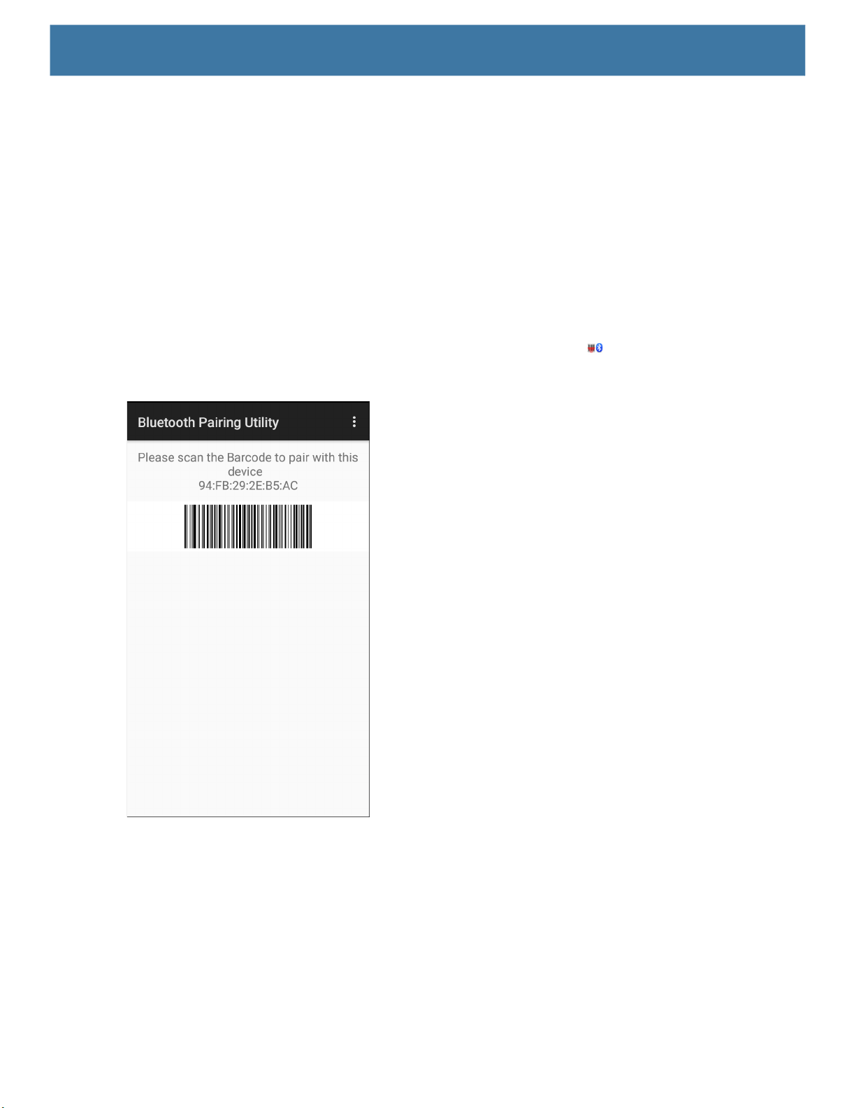
Pairing a Bluetooth Scanner
Connect the scanner to the device using one of the following methods:
• Simple Serial Interface (SSI) mode
• Bluetooth Human Interface Device (HID) mode.
Pairing Using Simple Serial Interface
To pair the scanner with the device using SSI:
1. Ensure that the two devices are within 10 meters (32.8 feet) of one another.
2. Install the battery into the scanner.
3. On the device swipe up from the bottom of the Home screen and touch .
Figure 40 Bluetooth Pairing Utility
Data Capture
4. Using the scanner, scan the barcode on the screen.
The scanner emits a high/low/high/low beeps. The Scan LED flashes green indicating that the scanner is
attempting to establish connection with the device. When connection is established, the Scan LED turns off
and the scanner emits one string of low/high beeps.
5. On the device touch the Home button.
Pairing Using Bluetooth Human Interface Device
To pair the scanner with the device using HID:
1. Remove the battery from the scanner.
80
Page 81

2. Replace the battery.
3. After the scanner reboots, scan the barcode below to place the scanner in HID mode.
4. On the device, swipe down from the Status bar to open the Quick Access panel and then touch .
5. Touch Bluetooth.
6. Touch Pair new device. The device begins searching for discoverable Bluetooth devices in the area and
displays them under Available devices.
7. Scroll through the list and select XXXXX xxxxxx, where XXXXX is the scanner and xxxxxx is the serial
number.
The device connects to the scanner, the scanner beeps once and Connected appears below the device
name. The Bluetooth device is added to the Paired devices list and a trusted (“paired”) connection is
established.
DataWedge
Data Capture
DataWedge is a utility that adds advanced barcode scanning capability to any application without writing code.
It runs in the background and handles the interface to built-in barcode scanners. The captured barcode data is
converted to keystrokes and sent to the target application as if it was typed on the keypad.
DataWedge allows any app on the device to get data from input sources such as a barcode scanner, MSR,
RFID, voice, or serial port and manipulate the data based on options or rules.
Configure DataWedge to
• Provide data capture services from any app.
• Use a particular scanner, reader or other peripheral device.
• Properly format and transmit data to a specific app.
To configure DataWedge refer to techdocs.zebra.com/datawedge/
Enabling DataWedge
1. Swipe up from the bottom of the Home screen and touch .
2. Touch > Settings.
3. Touch the DataWedge enabled checkbox. A blue checkmark appears in the checkbox indicating that
DataWedge is enabled.
4. Touch the Home button.
.
Disabling DataWedge
1. Touch .
2. Touch Settings.
3. Touch DataWedge enabled.
The blue check disappears from the checkbox indicating that DataWedge is disabled.
81
Page 82
Supported Decoders
NOTE: DataWedge supports the decoders listed below but not all are validated on this device.
Table 10 Supported Decoders
Decoders
Camera
SE4710
Internal Imager
Data Capture
RS5100
RS6000
DS2278
RS507/RS507X
DS3578
DS3678
LI3678
DS8178
Australian
Postal
Aztec X X X X X X X X -- X
Canadian
Postal
Chinese 2 of 5 O O O O O O O O O O
Codabar X X X X X X X X X X
Code 11 O O O O O O O O O O
Code 128 X X X X X X X X X X
Code 39 X X X X X X X X X X
Code 93 O O O O O O O O O O
Composite AB O O O O O O O O -- O
Composite C O O O O O O O O -- O
Discrete 2 of 5 O O O O O O O O O O
Datamatrix X X X X X X X X -- X
Dutch Postal O O O O O O O O -- O
DotCode X O O O O O O O O O
EAN13 X X X X X X X X X X
EAN8 X X X X X X X X X X
Grid Matrix O O O O O O O O O O
GS1 DataBar X X X X X X X X X X
GS1 DataBar
Expanded
O O O O O O O O -- O
O O O O -- -- -- -- -- --
X X X X X X X X X X
82
Page 83

Data Capture
Table 10 Supported Decoders (Continued)
Decoders
Camera
SE4710
Internal Imager
RS5100
RS6000
DS2278
RS507/RS507X
DS3578
DS3678
LI3678
DS8178
GS1 DataBar
Limited
GS1
Datamatrix
GS1 QRCode O O O O -- O O O -- O
HAN XIN O -- O O -- -- -- O O --
Interleaved 2
of 5
Japanese
Postal
Korean 3 of 5 O O O O O O O O O O
MAIL MARK X X X X -- X X X -- X
Matrix 2 of 5 O O O O O O O O O O
Maxicode X X X X X X X X -- X
MicroPDF O O O O O O O O -- O
MicroQR O O O O O O O O -- O
MSI O O O O O O O O O O
PDF417 X X X X X X X X -- X
QR Code X X X X X X X X -- X
Decoder
Signature
TLC 39 O O O O O O O O O O
Trioptic 39 O O O O O O O O O O
UK Postal O O O O O O O O -- O
UPCA X X X X X X X X X X
UPCE0 X X X X X X X X X X
UPCE1 O O O O O O O O O O
US4state O O O O O O O O -- O
O O O O O O O O O O
O O O O -- O O O -- O
O O O O O O O O O O
O O O O O O O O -- O
O O O O O O -- -- -- --
83
Page 84
Data Capture
Table 10 Supported Decoders (Continued)
Decoders
Camera
US4state FICS O O O O O O O O -- O
US Planet O O O O O O O O -- O
US Postnet O O O O O O O O -- O
SE4710
Internal Imager
RS5100
RS6000
DS2278
RS507/RS507X
DS3578
DS3678
LI3678
DS8178
Key
X = Enabled
O = Disabled
-- = Not Supported
Touch the Back button to return to the previous screen.
84
Page 85

Wireless
This section provides information on the following wireless features:
• Wireless Local Area Network (WLAN)
• Bluetooth
• Cast
• Near Field Communications (NFC)
Wireless Local Area Networks
Wireless local area networks (WLANs) allow the device to communicate wirelessly inside a building.
Before using the device on a WLAN, the facility must be set up with the required hardware to run the
WLAN (sometimes known as infrastructure). The infrastructure and the device must both be properly
configured to enable this communication.
Refer to the documentation provided with the infrastructure (access points (APs), access ports,
switches, Radius servers, etc.) for instructions on how to set up the infrastructure.
Once the infrastructure is set up to enforce the chosen WLAN security scheme, use the Wireless &
networks settings configure the device to match the security scheme.
The device supports the following WLAN security options:
• Open
• Wireless Equivalent Privacy (WEP)
• Wi-Fi Protected Access (WPA)/WPA2 Personal (PSK)
• WPA/WPA2/WPA3 Enterprise (EAP)
• Protected Extensible Authentication Protocol (PEAP) - with MSCHAPV2 and GTC
authentication.
• Transport Layer Security (TLS)
• Tunneled Transport Layer Security (TTLS) - with Password Authentication Protocol (PAP),
MSCHAP and MSCHAPv2 authentication
• Password (PWD)
• Lightweight Extensible Authentication Protocol (LEAP).
The Status bar displays icons that indicate Wi-Fi network availability and Wi-Fi status.
NOTE: To extend the life of the battery, turn off Wi-Fi when not in use.
85
Page 86

Connecting to a Wi-Fi Network
To connect to a Wi-Fi network:
1. Go to Settings.
2. Touch Wi-Fi to open the Wi-Fi screen. The device searches for WLANs in the area and lists them.
3. Scroll through the list and select the desired WLAN network.
4. For open networks, touch profile once or press and hold and then select Connect or for secure networks
enter the required password or other credentials then touch Connect. See the system administrator for
more information.
The device obtains a network address and other required information from the network using the dynamic
host configuration protocol (DHCP) protocol. To configure the device with a fixed internet protocol (IP)
address, see Configuring the Device to Use a Static IP Address.
5. In the Wi-Fi setting field, Connected appears indicating that the device is connected to the WLAN.
Removing a Wi-Fi Network
To remove a remembered or connected network:
Wireless
1. Go to Settings.
2. Touch Network & Internet > W-Fi.
3. Scroll down to the bottom of the list and touch Saved networks.
4. Touch the name of the network.
5. Touch FORGET.
6. Touch the Home button.
WLAN Configuration
This section provides information on configuring Wi-Fi settings.
Configuring a Secure Wi-Fi Network
1. Go to Settings.
2. Touch Network & Internet > Wi-Fi.
3. Slide the switch to the ON position.
4. The device searches for WLANs in the area and lists them on the screen.
5. Scroll through the list and select the desired WLAN network.
6. Touch the desired network. If the network security is Open, the device automatically connects to the
network. For all other network security a dialog box appears.
7. If the network security is WPA/WPA2-Personal or WEP, enter the required password and then touch
Connect.
8. If the network security is WPA/WPA2/WPA3 Enterprise:
• Touch the EAP method drop-down list and select one of the following:
• PEAP
86
Page 87

Wireless
• TLS
• TTLS
• PWD
• LEAP.
• Touch the Phase 2 authentication drop-down list and select an authentication method.
• If required, touch CA certificate and select a Certification Authority (CA) certificate. Note: Certificates
are installed using the Security settings.
• If required, touch User certificate and select a user certificate. Note: User certificates are installed
using the Location & security settings.
• If required, in the Identity text box, enter the username credentials.
• If desired, in the Anonymous identity text box, enter an anonymous identity username.
• If required, in the Password text box, enter the password for then given identity.
NOTE: By default, the network Proxy is set to None and the IP settings is set to DHCP. See Configuring for a
Proxy Server for setting connection to a proxy server and see Configuring the Device to Use a Static IP
Address for setting the device to use a static IP address.
9. Touch Connect.
10.Touch the Home button.
Manually Adding a Wi-Fi Network
Manually add a Wi-Fi network if the network does not broadcast its name (SSID) or to add a Wi-Fi network
when out of range.
1. Go to Settings.
2. Touch Network & Internet > Wi-Fi.
3. Slide the Wi-Fi switch to the On position.
4. Scroll to the bottom of the list and select Add network.
5. In the Network name text box, enter the name of the Wi-Fi network.
6. In the Security drop-down list, set the type of security to:
• None
• WEP
• WPA/WPA2-Personal
• WPA/WPA2/WPA3-Enterprise
7. If the network security is None, touch Save.
8. If the network security is WEP or WPA/WPA2-Personal, enter the required password and then touch Save.
9. If the network security is WPA/WPA2/WPA3-Enterprise:
• Touch the EAP method drop-down list and select one of the following:
• PEAP
• TLS
• TTLS
87
Page 88

Wireless
• PWD
• LEAP.
• Touch the Phase 2 authentication drop-down list and select an authentication method.
• If required, touch CA certificate and select a Certification Authority (CA) certificate. Note: Certificates
are installed using the Security settings.
• If required, touch User certificate and select a user certificate. Note: User certificates are installed
using the Security settings.
• If required, in the Identity text box, enter the username credentials.
• If desired, in the Anonymous identity text box, enter an anonymous identity username.
• If required, in the Password text box, enter the password for the given identity.
NOTE: By default, the network Proxy is set to None and the IP settings is set to DHCP. See Configuring for a
Proxy Server on page 88 for setting connection to a proxy server and see Configuring the Device to Use a
Static IP Address on page 89 for setting the device to use a static IP address.
10.Touch Save. To connect to the saved network, touch and hold on the saved network and select Connect to
network.
11.Touch the Home button.
Configuring for a Proxy Server
A proxy server is a server that acts as an intermediary for requests from clients seeking resources from other
servers. A client connects to the proxy server and requests some service, such as a file, connection, web
page, or other resource, available from a different server. The proxy server evaluates the request according to
its filtering rules. For example, it may filter traffic by IP address or protocol. If the request is validated by the
filter, the proxy provides the resource by connecting to the relevant server and requesting the service on behalf
of the client.
It is important for enterprise customers to be able to set up secure computing environments within their
companies, making proxy configuration essential. Proxy configuration acts as a security barrier ensuring that
the proxy server monitors all traffic between the Internet and the intranet. This is normally an integral part of
security enforcement in corporate firewalls within intranets.
1. Go to Settings.
2. Touch Network & Internet > Wi-Fi.
3. Slide the Wi-Fi switch to the On position.
4. In the network dialog box, select and touch a network.
5. Touch Advanced options.
6. Touch Proxy and select Manual.
7. In the Proxy hostname text box, enter the address of the proxy server.
8. In the Proxy port text box, enter the port number for the proxy server.
9. In the Bypass proxy for text box, enter addresses for web sites that are not required to go through the
proxy server. Use a comma “,” between addresses. Do not use spaces or carriage returns between
addresses.
10.Touch Connect.
11.Touch the Home button.
88
Page 89

Wireless
Configuring the Device to Use a Static IP Address
By default, the device is configured to use Dynamic Host Configuration Protocol (DHCP) to assign an Internet
protocol (IP) address when connecting to a wireless network.
1. Go to Settings.
2. Touch Network & Internet > Wi-Fi.
3. Slide the Wi-Fi switch to the On position.
4. In the network dialog box, select and touch a network.
5. Touch Advanced options.
6. Touch IP settings and select Static.
7. In the IP address text box, enter an IP address for the device.
8. If required, in the Gateway text box, enter a gateway address for the device.
9. If required, in the Network prefix length text box, enter the prefix length.
10.If required, in the DNS 1 text box, enter a Domain Name System (DNS) address.
11.If required, in the DNS 2 text box, enter a DNS address.
12.Touch Connect.
13.Touch the Home button.
Wi-Fi Preferences
Use the Wi-Fi preferences to configure advanced Wi-Fi settings. From the Wi-Fi screen scroll down to the
bottom of the screen and touch Wi-Fi preferences.
• Turn on W-Fi automatically - When enabled, Wi-Fi automatically turns back on when near high quality
saved networks.
• Open network notification - When enabled, notifies the user when an open network is available.
• Advanced - Touch to expand options.
• Additional settings - See Additional Settings.
• Install Certificates – Touch to install certificates.
• Network rating provider - Disabled (AOSP devices). To help determine what constitutes a good Wi-Fi
network, Android supports external Network rating providers that provide information about the quality of
open Wi-Fi networks. Select one of the providers listed or None. If none are available or selected, the
Connect to open networks feature is disabled.
• Wi-Fi Direct - Displays a list of devices available for a direct Wi-Fi connection.
• MAC address - Displays the Media Access Control (MAC) address of the device when connecting to
Wi-Fi networks.
• IP address - Displays the IP address of the device when connecting to Wi-Fi networks.
Additional Wi-Fi Settings
NOTE: Additional Wi-Fi settings are for the device, not for a specific wireless network.
89
Page 90

Wireless
Use the Additional Settings to configure additional Wi-Fi settings. To view the additional Wi-Fi settings, scroll
to the bottom of the Wi-Fi screen and touch Wi-Fi Preferences > Advanced > Additional settings.
• Regulatory
• Country Selection - Displays the acquired country code if 802.11d is enabled, else it displays the
currently selected country code.
• Region code - Displays the current region code.
• Band and Channel Selection
• Wi-Fi frequency band - Set the frequency band to: Auto (default), 5 GHz only or 2.4 GHz only.
• Available channels (2.4 GHz) - Touch to display the Available channels menu. Select specific
channels and touch OK.
• Available channels (5 GHz) - Touch to display the Available channels menu. Select specific channels
and touch OK.
• Logging
• Advanced Logging – Touch to enable advanced logging or change the log directory.
• Wireless logs - Use to capture Wi-Fi log files.
• Fusion Logger - Touch to open the Fusion Logger application. This application maintains a history
of high level WLAN events which helps to understand the status of connectivity.
• About
Wi-Fi Direct
Wi-Fi Direct devices can connect to each other without having to go through an access point. Wi-Fi Direct
devices establish their own ad-hoc network when required, letting you see which devices are available and
choose which one you want to connect to.
1. Go to Settings.
2. Touch Wi-Fi > Wi-Fi preferences > Advanced > Wi-Fi Direct. The device begins searching for another
3. Under Peer devices, touch the other device name.
4. On the other device, select Accept.
Connected appears on the device. On both devices, in their respective Wi-Fi Direct screens, the other device
name appears in the list.
Bluetooth
• Fusion Status - Touch to display live status of WLAN state. Also provides information about the
device and connected profile.
• Version - Displays the current Fusion information.
Wi-Fi Direct device.
Bluetooth devices can communicate without wires, using frequency-hopping spread spectrum (FHSS) radio
frequency (RF) to transmit and receive data in the 2.4 GHz Industry Scientific and Medical (ISM) band
(802.15.1). Bluetooth wireless technology is specifically designed for short-range (10 m (32.8 ft))
communication and low power consumption.
Devices with Bluetooth capabilities can exchange information (for example, files, appointments, and tasks)
with other Bluetooth enabled devices such as printers, access points, and other mobile devices.
90
Page 91

The device supports Bluetooth Low Energy. Bluetooth Low Energy is targeted at applications in the healthcare,
fitness, security, and home entertainment industries. It provides reduced power consumption and cost while
maintaining standard Bluetooth range.
Adaptive Frequency Hopping
Adaptive Frequency Hopping (AFH) is a method of avoiding fixed frequency interferers, and can be used with
Bluetooth voice. All devices in the piconet (Bluetooth network) must be AFH-capable in order for AFH to work.
There is no AFH when connecting and discovering devices. Avoid making Bluetooth connections and
discoveries during critical 802.11b communications. AFH for Bluetooth consists of four main sections:
• Channel Classification - A method of detecting an interference on a channel-by-channel basis, or
pre-defined channel mask.
• Link Management - Coordinates and distributes the AFH information to the rest of the Bluetooth network.
• Hop Sequence Modification - Avoids interference by selectively reducing the number of hopping channels.
• Channel Maintenance - A method for periodically re-evaluating the channels.
When AFH is enabled, the Bluetooth radio “hops around” (instead of through) the 802.11b high-rate channels.
AFH coexistence allows enterprise devices to operate in any infrastructure.
The Bluetooth radio in this device operates as a Class 2 device power class. The maximum output power is 2.5
mW and the expected range is 10 m (32.8 ft). A definition of ranges based on power class is difficult to obtain
due to power and device differences, and whether in open space or closed office space.
Wireless
NOTE: It is not recommended to perform Bluetooth wireless technology inquiry when high rate 802.11b
operation is required.
Security
The current Bluetooth specification defines security at the link level. Application-level security is not specified.
This allows application developers to define security mechanisms tailored to their specific need. Link-level
security occurs between devices, not users, while application-level security can be implemented on a per-user
basis. The Bluetooth specification defines security algorithms and procedures required to authenticate
devices, and if needed, encrypt the data flowing on the link between the devices. Device authentication is a
mandatory feature of Bluetooth while link encryption is optional.
Pairing of Bluetooth devices is accomplished by creating an initialization key used to authenticate the devices
and create a link key for them. Entering a common personal identification number (PIN) in the devices being
paired generates the initialization key. The PIN is never sent over the air. By default, the Bluetooth stack
responds with no key when a key is requested (it is up to user to respond to the key request event).
Authentication of Bluetooth devices is based-upon a challenge-response transaction. Bluetooth allows for a
PIN or passkey used to create other 128-bit keys used for security and encryption. The encryption key is
derived from the link key used to authenticate the pairing devices. Also worthy of note is the limited range and
fast frequency hopping of the Bluetooth radios that makes long-distance eavesdropping difficult.
Recommendations are:
• Perform pairing in a secure environment
• Keep PIN codes private and do not store the PIN codes in the device
• Implement application-level security.
91
Page 92

Bluetooth Profiles
The device supports the Bluetooth services listed.
Table 11 Bluetooth Profiles
Profile Description
Service Discovery Protocol
(SDP)
Serial Port Profile (SPP) Allows use of RFCOMM protocol to emulate serial cable
Object Push Profile (OPP) Allows the device to push and pull objects to and from a push
Advanced Audio Distribution
Profile (A2DP)
Audio/Video Remote Control
Profile (AVRCP)
Personal Area Network (PAN) Allows the use of Bluetooth Network Encapsulation Protocol to
Human Interface Device Profile
(HID)
Headset Profile (HSP) Allows a hands-free device, such as a Bluetooth headset, to place
Hands-Free Profile (HFP) Allows car hands-free kits to communicate with the device in the
Phone Book Access Profile
(PBAP)
Out of Band (OOB) Allows exchange of information used in the pairing process. Pairing
Symbol Serial Interface (SSI) Allows for communication with Bluetooth Imager.
Generic Attribute Profile (GATT) Provides profile discovery and description services for Bluetooth
Dial Up Networking (DUN) Provides a standard to access the Internet and other dial-up
Generic Access Profile (GAP) Use for device discovery and authentication.
OBject EXchange (OBEX) Facilitates the exchange of binary objects between devices.
Wireless
Handles the search for known and specific services as well as
general services.
connection between two Bluetooth peer devices. For example,
connecting the device to a printer.
server.
Allows the device to stream stereo-quality audio to a wireless
headset or wireless stereo speakers.
Allows the device to control A/V equipment to which a user has
access. It may be used in concert with A2DP.
provide L3 networking capabilities over a Bluetooth link. Only
PANU role is supported.
Allows Bluetooth keyboards, pointing devices, gaming devices and
remote monitoring devices to connect to the device.
and receive calls on the device.
car.
Allows exchange of Phone Book Objects between a car kit and a
mobile device to allow the car kit to display the name of the
incoming caller; allow the car kit to download the phone book so
you can initiate a call from the car display.
is completed using the Bluetooth radio, but requires information
from the OOB mechanism. Using OOB with NFC enables pairing
when devices simply get close, rather than requiring a lengthy
discovery process.
Low Energy protocol. It defines how attributes are grouped
together into sets to form services.
services over Bluetooth.
92
Page 93

Bluetooth Power States
The Bluetooth radio is off by default.
• Suspend - When the device goes into suspend mode, the Bluetooth radio stays on.
• Airplane Mode - When the device is placed in Airplane Mode, the Bluetooth radio turns off. When Airplane
mode is disabled, the Bluetooth radio returns to the prior state. When in Airplane Mode, the Bluetooth radio
can be turned back on if desired.
Bluetooth Radio Power
Turn off the Bluetooth radio to save power or if entering an area with radio restrictions (for example, an
airplane). When the radio is off, other Bluetooth devices cannot see or connect to the device. Turn on the
Bluetooth radio to exchange information with other Bluetooth devices (within range). Communicate only with
Bluetooth radios in close proximity.
NOTE: To achieve the best battery life, turn off radios when not in use.
Enabling Bluetooth
Wireless
1. Swipe down from the Status bar to open the Notification panel.
2. Touch to turn Bluetooth on.
3. Touch the Home button.
Disabling Bluetooth
1. Swipe down from the Status bar to open the Notification panel.
2. Touch to turn Bluetooth off.
3. Touch the Home button.
Discovering Bluetooth Device(s)
The device can receive information from discovered devices without pairing. However, once paired, the device
and a paired device exchange information automatically when the Bluetooth radio is on.
1. Ensure that Bluetooth is enabled on both devices.
2. Ensure that the Bluetooth device to discover is in discoverable mode.
3. Ensure that the two devices are within 10 meters (32.8 feet) of one another.
4. Swipe down from the Status bar to open the Quick Access panel.
5. Touch and hold Bluetooth.
6. Touch Pair new device. The device begins searching for discoverable Bluetooth devices in the area and
displays them under Available devices.
7. Scroll through the list and select a device. The Bluetooth pairing request dialog box appears.
8. Touch Pair on both devices.
9. The Bluetooth device is added to the Paired devices list and a trusted (“paired”) connection is established.
93
Page 94

Changing the Bluetooth Name
By default, the device has a generic Bluetooth name that is visible to other devices when connected.
1. Go to Settings.
2. Touch Connected devices > Connection preferences > Bluetooth.
3. If Bluetooth is not on, move the switch to turn Bluetooth on.
4. Touch Device name.
5. Enter a name and touch RENAME.
6. Touch the Home button.
Connecting to a Bluetooth Device
Once paired, connect to a Bluetooth device.
1. Go to Settings.
2. Touch Connected devices > Connection preferences > Bluetooth.
3. In the list, touch the unconnected Bluetooth device.
Wireless
When connected, Connected appears below the device name.
Selecting Profiles on the Bluetooth Device
Some Bluetooth devices have multiple profiles.
1. Go to Settings.
2. Touch Connected devices > Connection preferences > Bluetooth.
3. In the Paired Devices list, touch next to the device name.
4. Turn on or off a profile to allow the device to use that profile.
5. Touch the Home button.
Unpairing a Bluetooth Device
Unpairing a Bluetooth device erases all pairing information.
1. Go to Settings.
2. Touch Connected devices > Connection preferences > Bluetooth.
3. In the Paired Devices list, touch next to the device name.
4. Touch FORGET.
5. Touch the Home button.
Cast
Use Cast to mirror the device screen on a Miracast enabled wireless display.
1. Go to Settings.
2. Touch Connected devices > Connection preferences > Cast.
94
Page 95

3. Touch > Enable wireless display.
The device searches for nearby Miracast devices and lists them.
4. Touch a device to begin casting.
5. Touch the Home button.
Near Field Communications
NFC/HF RFID is a short-range wireless connectivity technology standard that enables secure transaction
between a reader and a contactless smartcard. The technology is based on ISO/IEC 14443 type A and B
(proximity) and ISO/IEC 15693 (vicinity) standards, using the HF 13.56 MHz unlicensed band.
The device supports the following operating modes:
• Reader mode
• Peer-to-Peer communication
• Card Emulation mode.
Using NFC, the device can:
• Read contactless cards such as contactless tickets, ID cards and ePassport.
Wireless
• Read and write information to contactless cards such as SmartPosters and tickets, as well as devices with
NFC interface such as vending machines.
• Read information from supported medical sensors.
• Pair with supported Bluetooth devices such as printers , ring scanners (ex. RS6000), and headsets (ex.
HS3100).
• Exchange data with another NFC device.
• Emulate contactless card such as payment, ticket, or SmartPoster.
The device NFC antenna is positioned to read NFC cards from the top of the device while the device is being
held.
Reading NFC Cards
Read contactless cards using NFC.
95
Page 96
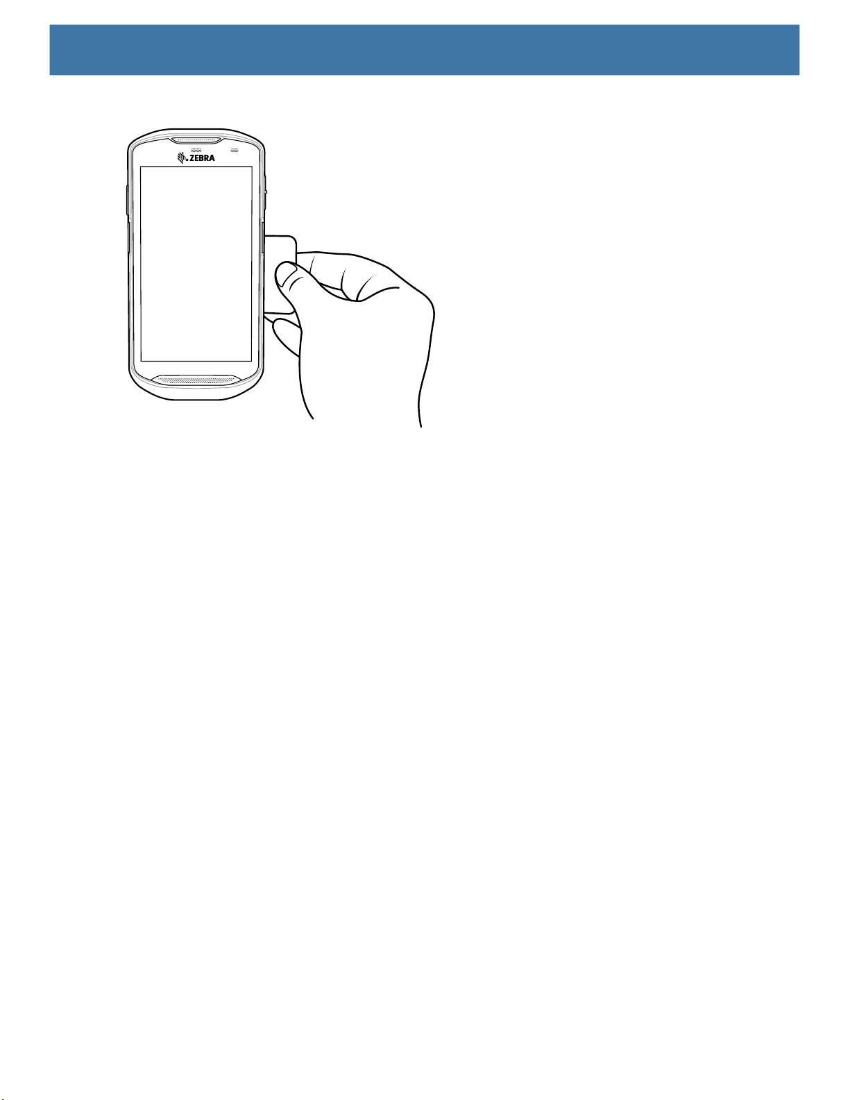
Figure 41 Reading Cards
1. Launch an NFC enabled application.
Wireless
2. Hold device as shown.
3. Move the device close to the NFC card until it detects the card.
4. Hold the card steadily until the transaction is complete (usually indicated by the application).
Sharing Information Using NFC
You can beam content like a web page, contact cards, pictures, YouTube links or location information from
your screen to another device by bringing the devices together back to back.
Make sure both devices are unlocked, support NFC, and have both NFC and Android Beam turned on.
1. Open a screen that contains a web page, video, photo or contact.
2. Move the back of the device toward the back of the other device.
Sharing Data Using NFC
96
Page 97
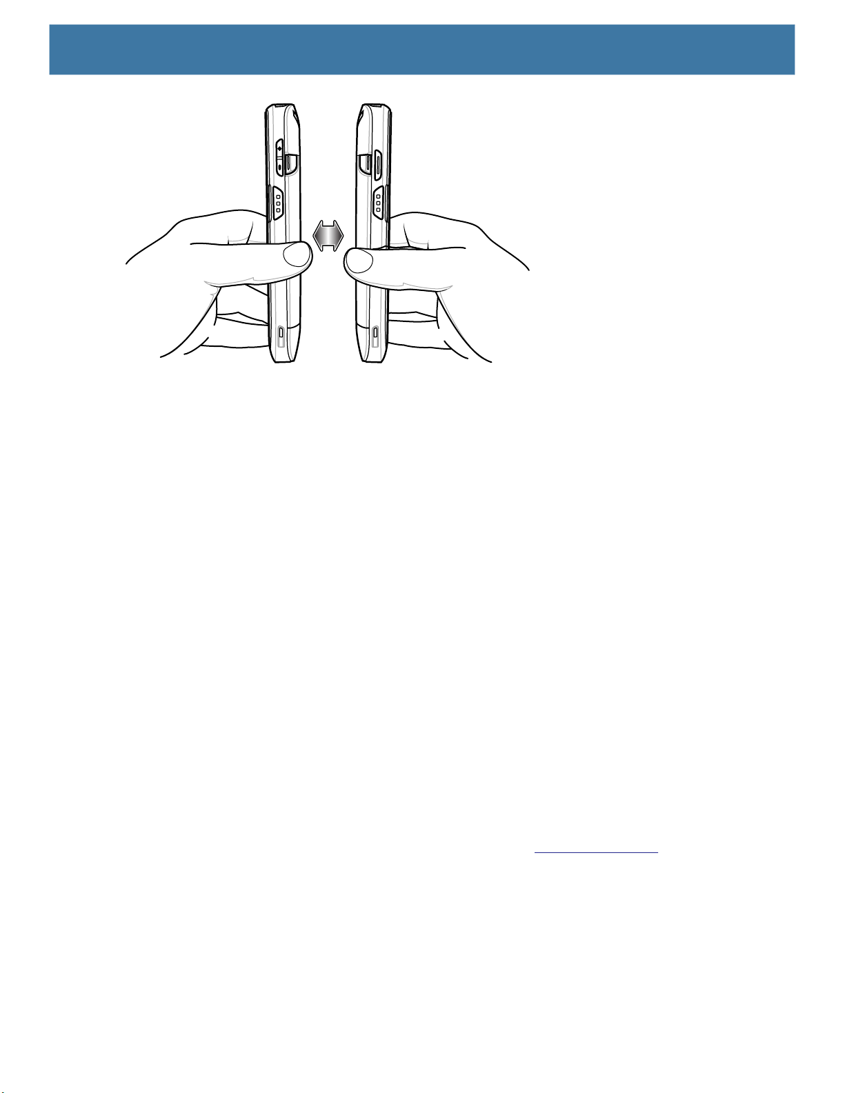
Wireless
When the devices connect, a sound emits, the image on the screen reduces in size, the message Touch to
beam displays.
3. Touch anywhere on the screen.
The transfer begins.
Enterprise NFC Settings
Improve NFC performance or increase battery life by selecting which NFC features to use on the device.
• Card Detection Mode - Select a card detection mode.
• Low - Increases battery life by lowering the NFC detection speed.
• Hybrid - Provides a balance between NFC detection speed and battery life (default).
• Standard - Provides the best NFC detection speed, but reduces battery life.
• Supported Card Technology - Select an option to detect only one NFC tag type, increasing battery life,
but reducing detection speed.
• All (Default) - Detects all NFC tag types. This provides the best detection speed, but reduces battery
life.
• ISO 14443 Type A/B
• FeliCa
• ISO15693
• Other NFC settings available with Zebra administrator tools (CSP) - Allows configuration of additional
Enterprise NFC Settings through staging tools and Mobile Device Management (MDM) solutions with an
MX version that supports the Enterprise NFC Settings Configuration Service Provider (CSP). For more
information on using the Enterprise NFC Settings CSP, refer to: techdocs.zebra.com
.
97
Page 98

Accessories
This section provides information for using the accessories for the device. Table 12 lists the accessories
available for the device.
Table 12 Accessories
Accessory Part Number Description
Cradles
1-Slot USB/Charge Only
Cradle Kit
1-Slot Workstation Docking
Cradle
2-Slot USB/Ethernet
Cradle
4-Slot Charge Only Cradle
with Battery Charger Kit
5-Slot Charge Only Cradle
Kit
5-Slot Ethernet Cradle Kit CRD-TC51-5SETH-01 Provides device charging and provides
Cradle Mount BRKT-SCRD-SMRK-01 Mounts the 5-Slot Charge Only Cradle, 5-Slot
USB-Ethernet Adapter KT-TC51-ETH1-01 Provides USB and Ethernet communication
CRD-TC51-1SCU-01 Provides device charging and communication.
CRD-TC5X-1SWS-01 Provides device charging and contains
CRD-TC5X-2SETH Provides device and spare battery charging,
CRD-TC51-5SC4B-01 Charges up to four devices and four spare
CRD-TC51-5SCHG-01 Charges up to five devices. Includes, cradle,
Includes cradle, power supply
(PWR-BGA12V50W0WW) and DC line cord.
additional ports for HDMI, Ethernet, and USB
ports that enable device to be used as a
workstation computer when connected to a
HDMI monitor, keyboard and mouse. Includes
(PWR-BGA12V50W0WW) and DC line cord.
and USB and Ethernet communication.
Includes cradle, power supply
(PWR-BGA12V50W0WW) and DC line cord.
batteries. Includes cradle, power supply
(PWR-BGA12V108W0WW) and DC line cord
power supply (PWR-BGA12V108W0WW)
and DC line cord.
Ethernet communication for up to five
devices. Includes cradle, power supply
(PWR-BGA12V108W0WW) and DC line cord.
Ethernet Cradle, and 4-Slot Battery Charger
to a wall or rack.
with the 1-Slot USB/Charge Only Cradle Kit.
98
Page 99

Accessories
Table 12 Accessories (Continued)
Accessory Part Number Description
Batteries and Chargers
PowerPrecisionPlus
Battery
4-Slot Battery Charger Kit SAC-TC51-4SCHG-01 Charges up to four battery packs. Includes
Charge and Communication Cables
Rugged Charge/USB
Cable
Rugged USB-C Adapter ADPTR-TC56-USBC-01 Provides communication and power to the
USB-C Communication
and Charge Cable
USB Communication
Cable
Audio Accessories
2.5 mm Audio Adapter CBL-TC51-HDST25-01 Plugs into the device and provides audio to a
2.5 mm Headset HDST-25MM-PTVP-01 Use for PTT and VoIP calls.
3.5 mm Audio Adapter CBL-TC51-HDST35-01 Plugs into the device and provides audio to a
3.5 mm Headset HDST-35MM-PTVP-01 Use for PTT and VoIP calls.
Miscellaneous
Rugged Boot SG-TC5X-EXO1-01 Provides additional protection for the device.
Trigger Handle TRG-TC51-SNP1-01 Adds gun-style handle with a scanner trigger
Trigger Handle Kit (with
Rugged Boot)
Screen Protector KT-TC51-SCRNP1-01 Add additional screen protection.
SmartDEX Solution DEX30 Provides wireless DEX communications to the
Wrist Lanyard SG-PD40-WLD1-01 Use to hold the device on wrist. For use with
Rugged I/O Connector ADP-TC51-RGIO1-03 Replacement Rugged I/O Connector (3-pack).
Carrying Solutions
Soft Holster SG-TC51-HLSTR1-01 Use to hold the device on hip. Accepts device
BTRY-TC51-43MA1-01
BTRY-TC51-43MA1-10
CBL-TC51-USB1-01 Provides communication and power to the
CBL-TC5X-USBC2A-01 Provides UBC-A to USB-C communication
25-124330-01R Provides micro USB to USB communication
TRG-TC51-TRG1-01 Adds gun-style handle with a scanner trigger
Replacement battery (single pack).
Replacement battery (10–pack).
cradle, power supply
(PWR-BGA12V50W0WW) and DC line cord.
device. Requires power supply
PWR-WUA5V12W0xx.
device using a USB-C cable
(CBL-TC5X-USBC2A-01).
and power to the device.
for use with 1-Slot USB/Charge Only Cradle
Kit.
wired headset with 2.5 mm plug.
wired headset with collared 3.5 mm plug.
for comfortable and productive scanning.
Requires Rugged Boot.
for comfortable and productive scanning.
device.
Trigger Handle or Rugged Boot.
with Rugged Boot and Trigger Handle
99
Page 100

Accessories
Table 12 Accessories (Continued)
Accessory Part Number Description
Hand Strap SG-TC51-EHDSTP1-03 Replacement hand strap with hand strap
mounting clip (3–pack).
Basic Hand Strap SG-TC51-BHDSTP1-03 Provide a hand strap to assist in holding the
device without a Rugged Boot.
Stylus and Coiled Tether SG-TC7X-STYLUS-03 Stylus with coiled tether (3-pack).
Power Supplies
Power Supply PWR-BGA12V50W0WW Provides power to the 1-Slot USB Charge
cradle and 4-Slot Spare Battery Charger.
Requires AC line cord.
Power Supply PWR-BGA12V108W0WW Provides power to the 4-Slot Charge Only
Cradle with battery Charger, 5-Slot Charge
Only cradle and the 5-Slot Ethernet Cradle.
Requires DC Line Cord, p/n 50–16002–029R
and country specific three wire grounded AC
line cord sold separately.
Power Supply PWR-WUA5V12W0US Provides 12 VDC, 2.5 A power to the Rugged
Charge/USB cable. Includes plug adapter for
use in the United States.
Power Supply PWR-WUA5V12W0GB Provides 12 VDC, 2.5 A power to the Rugged
Charge/USB cable. Includes plug adapter for
use in the European Union.
Power Supply PWR-WUA5V12W0EU Provides 12 VDC, 2.5 A power to the Rugged
Charge/USB cable. Includes plug adapter for
use in the United Kingdom.
Power Supply PWR-WUA5V12W0AU Provides 12 VDC, 2.5 A power to the Rugged
Charge/USB cable. Includes plug adapter for
use in Australia.
Power Supply PWR-WUA5V12W0CN Provides 12 VDC, 2.5 A power to the Rugged
Charge/USB cable. Includes plug adapter for
use in China.
Power Supply PWR-WUA5V12W0IN Provides 12 VDC, 2.5 A power to the Rugged
Charge/USB cable. Includes plug adapter for
use in India.
Power Supply PWR-WUA5V12W0KR Provides 12 VDC, 2.5 A power to the Rugged
Charge/USB cable. Includes plug adapter for
use in Korea.
Power Supply PWR-WUA5V12W0BR Provides 12 VDC, 2.5 A power to the Rugged
Charge/USB cable. Includes plug adapter for
use in Brazil.
DC Line Cord CBL-DC-381A1-01 Provides power from the power supply
(PWR-BGA12V108W0WW) to the 4-Slot
Charge Only Cradle with Battery Charger,
5-Slot Charge Only Cradle and 5-Slot
Ethernet Cradle.
100
 Loading...