

Page 1
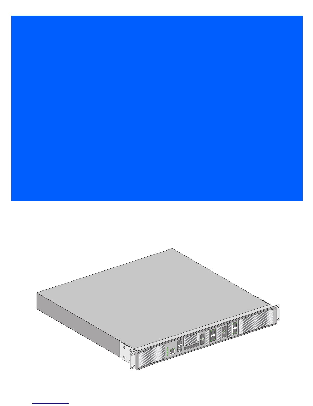
RFS7000 Series
INSTALLATION GUIDE
Page 2

2 RFS7000 Series
Zebra and the Zebra head graphic are registered trademarks of ZIH Corp. The Symbol logo is a registered trademark
of Symbol Technologies, Inc., a Zebra Technologies company.
© 2015 Symbol Technologies, Inc.
Page 3

Installation Guide 3
Introduction . . . . . . . . . . . . . . . . . . . . . . . . . . . . . . . . . . . . . . . . . . . . . . . . . . 5
Package Contents . . . . . . . . . . . . . . . . . . . . . . . . . . . . . . . . . . . . . . . . . . . . . . . 5
Document Conventions . . . . . . . . . . . . . . . . . . . . . . . . . . . . . . . . . . . . . . . . . . . 5
Warnings . . . . . . . . . . . . . . . . . . . . . . . . . . . . . . . . . . . . . . . . . . . . . . . . . . . . . . 5
Site Preparation . . . . . . . . . . . . . . . . . . . . . . . . . . . . . . . . . . . . . . . . . . . . . . . . 6
Specifications . . . . . . . . . . . . . . . . . . . . . . . . . . . . . . . . . . . . . . . . . . . . . . . . 7
Physical Specifications . . . . . . . . . . . . . . . . . . . . . . . . . . . . . . . . . . . . . . . . . . . 7
Power Cord Specifications . . . . . . . . . . . . . . . . . . . . . . . . . . . . . . . . . . . . . . . . 7
Power Protection . . . . . . . . . . . . . . . . . . . . . . . . . . . . . . . . . . . . . . . . . . . . . . . . 7
LED Codes . . . . . . . . . . . . . . . . . . . . . . . . . . . . . . . . . . . . . . . . . . . . . . . . . . . . 8
System Status LEDs . . . . . . . . . . . . . . . . . . . . . . . . . . . . . . . . . . . . . . . . . . . . . 8
Start Up / POST (Primary System or Redundant System) . . . . . . . . . . . . . . . . . 8
Switch Status (Primary System) . . . . . . . . . . . . . . . . . . . . . . . . . . . . . . . . . . . . 9
Switch Status (Redundant System) . . . . . . . . . . . . . . . . . . . . . . . . . . . . . . . . . 9
Fan LED . . . . . . . . . . . . . . . . . . . . . . . . . . . . . . . . . . . . . . . . . . . . . . . . . . . . . . . 9
Temperature Status LED . . . . . . . . . . . . . . . . . . . . . . . . . . . . . . . . . . . . . . . . . 10
RJ-45 Gigabit Ethernet LEDs . . . . . . . . . . . . . . . . . . . . . . . . . . . . . . . . . . . . . . 11
RJ-45 Port Speed LED . . . . . . . . . . . . . . . . . . . . . . . . . . . . . . . . . . . . . . . . . . . 11
RJ-45 Port Status LED . . . . . . . . . . . . . . . . . . . . . . . . . . . . . . . . . . . . . . . . . . . 11
SFP Gigabit Ethernet LEDs . . . . . . . . . . . . . . . . . . . . . . . . . . . . . . . . . . . . . . . 12
SFP Port Speed LED . . . . . . . . . . . . . . . . . . . . . . . . . . . . . . . . . . . . . . . . . . . . . 12
SFP Port Status LED . . . . . . . . . . . . . . . . . . . . . . . . . . . . . . . . . . . . . . . . . . . . 12
Out of Band Management Port LEDs . . . . . . . . . . . . . . . . . . . . . . . . . . . . . . . 13
Out of Band Management Port Speed LED . . . . . . . . . . . . . . . . . . . . . . . . . . . 13
Out of Band Management Port Status LED . . . . . . . . . . . . . . . . . . . . . . . . . . 13
Hardware Setup . . . . . . . . . . . . . . . . . . . . . . . . . . . . . . . . . . . . . . . . . . . . . . 14
Cabling Information . . . . . . . . . . . . . . . . . . . . . . . . . . . . . . . . . . . . . . . . . . . . . 14
Gigabit Ethernet on the RFS7010. . . . . . . . . . . . . . . . . . . . . . . . . . . . . . . . . . . 15
Installing Gigabit Ethernet SFPs . . . . . . . . . . . . . . . . . . . . . . . . . . . . . . . . . . . 15
Page 4

4 RFS7000 Series
Connecting USB Devices . . . . . . . . . . . . . . . . . . . . . . . . . . . . . . . . . . . . . . . . . 17
Installing a Compact Flash Card . . . . . . . . . . . . . . . . . . . . . . . . . . . . . . . . . . . 18
Rack Mount Instructions . . . . . . . . . . . . . . . . . . . . . . . . . . . . . . . . . . . . . . . . . 19
RFS7000 Series Console Port Setup . . . . . . . . . . . . . . . . . . . . . . . . . . . . . . . . 20
Supplying Power to the RFS7000 Series . . . . . . . . . . . . . . . . . . . . . . . . . . . . . 20
Verifying the Installation . . . . . . . . . . . . . . . . . . . . . . . . . . . . . . . . . . . . . . . . . 22
Regulatory Information . . . . . . . . . . . . . . . . . . . . . . . . . . . . . . . . . . . . . . . . 23
Waste Electrical and Electronic Equipment (WEEE) . . . . . . . . . . . . . . 25
Support . . . . . . . . . . . . . . . . . . . . . . . . . . . . . . . . . . . . . . . . . . . . . . . . . . . . . 27
End-User License Agreement . . . . . . . . . . . . . . . . . . . . . . . . . . . . . . . . . . 28
Page 5

Installation Guide 5
!
1 Introduction
The RFS7000 Series provides centralized Wireless LAN (WLAN) configuration and management by coalescing a
network “intelligence” previously spread across physically distributed access points. The RFS7000 Series is a
WLAN’s single point of contact, thus reducing wireless networking complexity by moving management out of the
ceiling and into the wiring closet. In addition, through the use of patented Virtual AP architecture, the RFS7000
Series lets you create multiple WLANs without changing or adding to the existing wired network infrastructure.
This document is written for the network device installer.
1.1 Package Contents
Inspect the package contents and report any missing or damaged items to your sales representative. The package
should contain the following:
• RFS7010 with Rack Brackets installed
• Console Cable
• Installation Guide (this document)
• China RoHS compliance document
1.2 Document Conventions
The following graphical alerts are used in this document to indicate notable situations:
NOTE Tips, hints, or special requirements that you should take note of.
CAUTION Care is required. Disregarding a caution can result in data loss or
equipment malfunction.
WARNING!Indicates a condition or procedure that could result in personal injury or
equipment damage.
1.3 Warnings
• Read all installation instructions and site survey reports, and verify correct equipment installation before connecting the system to its
power source.
• Remove jewelry and watches before installing this equipment.
• Install the equipment in a rack with adequate dimensions and weight allowances.
• Verify the rack is anchored and cannot tip over or break away from its mountings.
• Verify the unit is grounded before connecting it to the power source.
• Verify any device connected to this unit is properly wired and grounded.
Page 6

6 RFS7000 Series
• Connect all power cords to a properly wired and grounded electrical circuit.
• Verify the electrical circuits have appropriate overload protection.
• Attach only approved power cords to the device.
• Verify that the power connector and socket are accessible at all times during the operation of the equipment.
• Do not work with power circuits in dimly lit spaces.
• Do not install this equipment or work with its power circuits during thunderstorms or other weather conditions that could cause a
power surge.
• Verify there is adequate ventilation around the device, and ambient temperatures meet equipment operation specifications.
1.4 Site Preparation
• Consult your site survey and network analysis reports to determine specific equipment placement, port capacity, power drops, and so
on.
• Assign installation responsibility to the appropriate personnel.
• Identify where all installed components are located.
• Verify appropriate rack mounting requirements.
• Provide a sufficient number of power drops for your equipment.
• Ensure adequate, dust-free ventilation to all installed equipment.
• Identify and prepare Ethernet and console port connections.
• Verify that cable lengths are within the maximum allowable distances for optimal signal transmission.
• Verify that the RFS7000 Series is powered through an Uninterruptible Power Supply (UPS).
Page 7

Installation Guide 7
2 Specifications
2.1 Physical Specifications
Width 440mm (17.32 in)
Height 44.45mm (1.75 in)
Depth 390.8mm (15.38 in)
Weight 6.12 Kg (13.5 lbs)
Operating Temperature 0°C - 40°C
Operating Humidity 5% - 85% RH, non-condensing
Operating Altitude 3 km (10000 ft)
2.2 Power Cord Specifications
A power cord is not supplied. Use only a correctly rated power cord certified (as appropriate) for the country of
operation
.
2.2.1 Power Protection
• If possible, use a circuit dedicated to data processing equipment. Commercial electrical contractors
are familiar with wiring for data processing equipment and can help with the load balancing of these circuits.
• Install surge protection. Be sure to use a surge protection device between the electricity source and the
RFS7000 Series.
• Install an Uninterruptible Power Supply (UPS). A UPS provides continuous power during a power
outage. Some UPS devices have integral surge protection. UPS equipment requires periodic maintenance to
ensure reliability. A UPS of the proper capacity for the data processing equipment must be purchased.
Page 8
8 RFS7000 Series
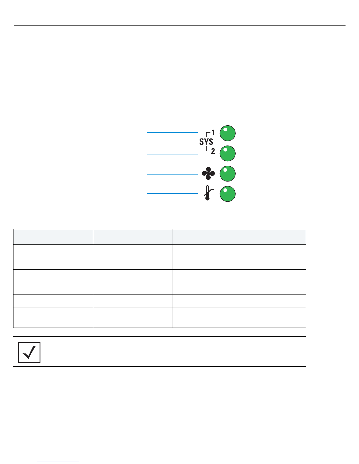
System Status 1
Fan status
Temperature status
System Status 2
3 LED Codes
The RFS7010 has four vertically-stacked LEDs on its front panel. Each of the Gigabit Ethernet ports have two
status LEDs. These LEDs display two colors (green & amber), and three lit states (solid, blinking, and off). The
following tables decode the combinations of LED colors and states for the System Status LEDs and the Gigabit
Ethernet LEDs.
3.1 System Status LEDs
3.1.1 Start Up / POST (Primary System or Redundant System)
System Status 1 LED System Status 2 LED Event
Off Off Power off
Green Blinking Green Blinking Power On Self Test (POST) running
Green Solid Green Blinking POST succeeded (Operating System Loading)
Green Solid Off POST succeeded (Normal Operation)
Amber Blinking Off POST Failure
Alternating Green Blinking
& Amber Blinking
NOTE
During start up, the Temperature status LED will be lit Solid Amber. This is
Alternating Green Blinking
& Amber Blinking
normal behavior and does not indicate an error. At the completion of start
up the Temperature Status LED will change to Solid Green.
Boot Up Error: Device has an invalid checksum
Page 9

Installation Guide 9
3.1.2 Switch Status (Primary System)
System Status 1 LED System Status 2 LED Event
Off Off Power off
Green Solid Off No Redundancy Feature Enabled
Green Solid Green Solid
Green Solid Amber Blinking
Redundancy Feature Enabled
Actively Adopting Access Ports
No License to adopt Access Ports
or
No Country Code configured
or
License and Country Code configured, but no
APs adopted
3.1.3 Switch Status (Redundant System)
System Status 1 LED System Status 2 LED Event
Off Off Power off
Green Solid Off No Redundancy Feature Enabled
Green Blinking Green Solid
Green Blinking
Alternating Green Blinking
& Amber Blinking
Redundant System failed over and adopting
ports
Redundant System not failed over.
No License to adopt Access Ports
or
Green Solid Amber Blinking
No Country Code configured
or
License and Country Code configured, but no
APs adopted
3.1.4 Fan LED
Fan LED Event
Off System Off / POST Start
Green Blinking POST in Process
Green Solid All System Fans Normal Operation
Amber Solid
Redundant Cooling Failure
System Operational
Page 10

10 RFS7000 Series
Fan LED Event
System Cooling Failure
Amber Blinking
System will be held in reset until the issue is
resolved
3.1.5 Temperature Status LED
Temperature LED Event
Off System Off
Green Solid
Amber Solid
Amber Blinking
Ambient Inlet Temperature is within specified
operating limit
Ambient Inlet Temperature is near the maximum
operating temperature
During start up this LED will be lit Solid Amber.
This is normal behavior and does not indicate an
error.
Ambient Inlet Temperature is above the
maximum specified operating temperature
System will be held in reset until the issue is
resolved
Page 11

Installation Guide 11
sym_006
Port
speed
Port
status
Port
speed
Port
status
3.2 RJ-45 Gigabit Ethernet LEDs
3.2.1 RJ-45 Port Speed LED
Port Speed LED Event
Off 10 Mbps
Green Solid 100 Mbps
Green Blinking 1000 Mbps
Amber Blinking Port Fault
3.2.2 RJ-45 Port Status LED
Port Status LED Event
Off No Link or Administratively shut down
Green Solid Link present
Green Blinking Activity: Transmit and Receive
Amber Blinking Link Fault
Page 12

12 RFS7000 Series
sym_
Port
speed
Port
status
Upper
Port
Lower
Port
3.3 SFP Gigabit Ethernet LEDs
3.3.1 SFP Port Speed LED
Port Speed LED Event
Green Blinking 1000 Mbps
Amber Blinking Module or Tx/Rx Fault Loss
3.3.2 SFP Port Status LED
Port Status LED Event
Off No Link or Administratively shut down
Green Solid Link present / Operational
Amber Blinking Module or Tx/Rx Fault Loss
Page 13

Installation Guide 13
sym_0
Port
speed
Port
status
3.4 Out of Band Management Port LEDs
3.4.1 Out of Band Management Port Speed LED
Port Speed LED Event
Off 10 Mbps
Green Solid 100 Mbps
Amber Blinking Port Fault
3.5 Out of Band Management Port Status LED
Port Status LED Event
Off No Link
Green Solid Link present
Green Blinking Activity: Transmit and Receive
Amber Blinking Link Fault
Page 14

14 RFS7000 Series
sym_023
Gigabit Ethernet
SFPs
Console
connector
Out-of-band
management
port
(ME Port)
Compact
Flash
USB
ports
Gigabit Ethernet
RJ45s
sym_005
Out-of-Band
Management
Gigabit
SFP
Port 1
Gigabit
Ethernet
Port 1
Console
Compact Flash
USB 1
USB 2
Gigabit
Ethernet
Port 2
Gigabit
SFP
Port 2
Gigabit
SFP
Port 3
Gigabit
SFP
Port 4
Gigabit
Ethernet
Port 3
Gigabit
Ethernet
Port 4
4 Hardware Setup
4.1 Cabling Information
The RFS7010 has four RJ-45 Gigabit Ethernet ports, four Gigabit SFP (fiber) ports, one Out-of-band management
port and one Console connector. The above diagram shows each of those ports and the cables or devices attached
to them. The sections that follow describe detailed connection and cabling information for each port.
Page 15

Installation Guide 15
Gigabit Ethernet
RJ45s
Gigabit Ethernet
SFPs
Open bail to insert or remove
SFP transceiver
4.2 Gigabit Ethernet on the RFS7010
The RFS7010 has four RJ-45 Gigabit Ethernet ports and four Gigabit SFP (fiber optic) ports. Using the RJ-45 ports
requires connecting a Category-6 Ethernet cable to the port. To use the Gigabit SFP ports, first install the SFP
Modules (Part Number: Fiber-3000-1S-WWR).
4.2.1 Installing Gigabit Ethernet SFPs
1. Open the bail on the transceiver.
Page 16

16 RFS7000 Series
2. Insert each of the SFP transceivers into the corresponding ports.
3. Once the SFP transceivers are properly seated in their ports, close the bails to lock the transceivers in place.
4. Insert the fiber optic cables into the installed transceivers.
Page 17

Installation Guide 17
USB
ports
4.3 Connecting USB Devices
The RFS7010 contains two USB ports for connecting USB flash storage devices to the RFS7010. The RFS7010 can
use the USB flash storage devices for file transfers and firmware updates. Follow the setup instructions below to
connect the devices to the RFS7010 and then access those devices through the Web UI or Command Line Interface.
1. Connect the USB flash drive to either of the USB ports.
2. Wait a few seconds for the drive to be recognized by the RFS7010.
3. Follow the instructions in the WiNG Controller and Service Platform System Reference Guide or CLI
Reference Guide for more information on accessing USB storage devices for file transfers or firmware
updates.
NOTE The RFS7010 supports USB flash devices formatted with FAT or VFAT
(FAT32) filesystems only. If your flash storage device is formatted with
another filesystem you will need to format
Page 18

18 RFS7000 Series
Compact
Flash slot
Compact Flash
4.4 Installing a Compact Flash Card
The RFS7010 contains a Compact Flash slot for file transfers, firmware updates and use by service technicians.
Follow the setup instructions below to connect a Compact Flash Card and then access that card through the Web UI.
1. To use a Compact Flash card with the RFS 7010 insert the card into the Compact Flash slot.
2. Once the Compact Flash card has been inserted, follow the instructions in the WiNG Controller and Service
Platform System Reference Guide or CLI Reference Guide to use the Compact Flash card for file transfers or
firmware updates.
Page 19

Installation Guide 19
4.5 Rack Mount Instructions
To install the RFS7000 Series in a rack:
1. The rack mounting brackets are installed at the factory. No additional steps are needed.
2. Attach the brackets to the rack using screws appropriate for your rack’s mounting holes.
Page 20

20 RFS7000 Series
sym_0
Rack mount
bracket
AC inlet
4.6 RFS7000 Series Console Port Setup
To add the RFS7000 Series to the network and prepare it for initial configuration:
1. Using the supplied console cable (pictured below), connect the RFS7000 Series serial port to an RS-232
(DB-9) serial port on a separate computer (the “configuration computer”).
2. On the configuration computer, configure a terminal emulation application
(such as HyperTerminal) as follows:
Terminal Type VT-100
Port COM port
19200bps transfer rate
8 data bits
Terminal Settings
no parity
1 stop bit
no flow control
no hardware compression
4.7 Supplying Power to the RFS7000 Series
1. Plug an approved AC power cord into the power connector at the back of the RFS7000 Series.
2. Plug the cord into a standard AC outlet with a voltage range of 100 to 240 VAC.
Page 21

Installation Guide 21
.
WARNING! An improper shutdown can render the RFS7000 Series inoperable such
that it could require service by support. Do not remove AC power without
first following the shutdown procedure. An abrupt loss of power can
corrupt the information stored on the device.
Page 22

22 RFS7000 Series
4.8 Verifying the Installation
View the LEDs on the front panel of the RFS7010 to ensure the device is functioning properly. The normal LED
pattern follows this path:
• During the Power On Self Test (POST), the System 1 and System 2 LEDs both blink green.
• If the POST test fails, the System 1 LED will blink amber. If the POST test succeeds, the System 1 LED will be
lit solid green.
• As the software is initialized, the System 2 LED will blink green.
• After the software has finished initializing, the System 1 LED will be lit solid green and the bottom System 2
LED will be off. The RFS7010 is ready to be configured, as described in the WiNG Controller and Service
Platform System Reference Guide.
• Other LED codes indicate the presence (or absence) of different standby states, or errors. A guide to the
RFS7000 Series LEDs codes is provided in Chapter 3, LED Codes.
Page 23

Installation Guide 23
!
5 Regulatory Information
This guide applies to Model Number RFS-7010
All Zebra devices are designed to be compliant with rules and regulations in locations they are sold and will be
labeled as required.
Local language translations are available at the following Website:www.zebra.com/support
Any changes or modifications to Zebra equipment, not expressly approved by Zebra, could void the user’s authority
to operate the equipment.
Zebra devices must be professionally installed and configured so that the Radio Frequency Output Power will not
exceed the maximum allowable limit for the country of operation.
Country Selection
Select only the country in which you are using the device. Any other selection will make the operation of this device
illegal.
Laser Devices - Gigabit Ethernet SFP Option
Complies with 21CFR1040.10 and 1040.11 except for deviations pursuant to Laser Notice No. 50, dated
July 26, 2001.
EN60825-1:1994+ A1:2002 +A2:2001
IEC60825-1:1993+A1:1997+A2:2001
The laser classification is marked on the device.
.
Class 1 Laser devices are not considered to be hazardous when used for their intended purpose. The following
statement is required to comply with US and international regulations:
Radio Frequency Interference Requirements - FCC
This equipment has been tested and found to comply with the limits for a Class A digital device, pursuant to Part 15 of the
FCC rules. These limits are designed to provide reasonable protection against harmful interference when the equipment is
operated in commercial environment. This equipment generates, uses, and can radiate radio frequency energy and, if not
installed and used in accordance with the instruction manual, may cause harmful interference to radio communications.
Operation of this equipment in a residential area is likely to cause harmful interference in which case the user will be
required to correct the interference at his own expense.
Radio Frequency Interference Requirements - Canada
This Class A digital apparatus complies with Canadian ICES-003.
Page 24

24 RFS7000 Series
!
この装置は、情報処理装置等電波障害自主規制協議会(VCCI)の基準に基づくクラスA
情報技術装置です。この装置を家庭環境で使用すると電波妨害を引き起こすことがありま
す。この場合には使用者が適切な対策を講ずるよう要求されることがあります。
Cet appareil numérique de la classe A est conforme à la norme NMB-003 du Canada.
Marking and European Economic Area (EEA)
CAUTION This is a class A product. In a domestic environment this product may
cause radio interference in which case the user may be required to take
adequate measures.
Statement of Compliance
Zebra hereby declares that this device is in compliance with the essential requirements and other relevant
provisions of Directive 1999/5/EC. A Declaration of Conformity may be obtained from www.zebra.com/doc
.
Japan (VCCI) - Voluntary Control Council for Interference
Class A ITE
This is a Class A product based on the standard of the Voluntary Control Council for Interference by Information
Technology Equipment (VCCI). If this equipment is used in a domestic environment, radio interference may occur,
in which case, the user may be required to take corrective actions.
Page 25

Installation Guide 25
5.1 Waste Electrical and Electronic Equipment (WEEE)
English: For EU Customers: All products at the end of their life must be returned to Zebra for recycling. For
information on how to return product, please go to: www.zebra.com/weee.
Français: Clients de l'Union Européenne: Tous les produits en fin de cycle de vie doivent être retournés à Zebra
pour recyclage. Pour de plus amples informations sur le retour de produits, consultez : www .zebra.com/weee.
Español: Para clientes en la Unión Europea: todos los productos deberán entregarse a Zebra al final de su ciclo
de vida para que sean reciclados. Si desea más información sobre cómo devolver un producto, visite:
www.zebra.com/weee
Български: За клиенти от ЕС: След края на полезния им живот всички продукти трябва да се връщат на
Zebra за рециклиране. За информация относно връщането на продукти, моля отидете на адрес:
www.zebra.com/weee
Deutsch: Für Kunden innerhalb der EU: Alle Produkte müssen am Ende ihrer Lebensdauer zum Recycling an
Zebra zurückgesandt werden. Informationen zur Rücksendung von Produkten finden Sie unter
www.zebra.com/weee
Italiano: per i clienti dell'UE: tutti i prodotti che sono giunti al termine del rispettivo ciclo di vita devono essere
restituiti a Zebra al fine di consentirne il riciclaggio. Per informazioni sulle modalità di restituzione, visitare il
seguente sito Web: www.zebra.com/weee
Português: Para clientes da UE: todos os produtos no fim de vida devem ser devolvidos à Zebra para
reciclagem. Para obter informações sobre como devolver o produto, visite: www.zebra.com/weee.
Nederlands: Voor klanten in de EU: alle producten dienen aan het einde van hun levensduur naar Zebra te
worden teruggezonden voor recycling. Raadpleeg www.zebra.com/weee
terugzenden van producten.
Polski: Klienci z obszaru Unii Europejskiej: Produkty wycofane z eksploatacji nale¿y zwróciæ do firmy Zebra w
celu ich utylizacji. Informacje na temat zwrotu produktów znajduj¹ siê na stronie internetowej
www.zebra.com/weee.
Čeština: Pro zákazníky z EU: Všechny produkty je nutné po skonèení jejich životnosti vrátit spoleènosti Zebra
k recyklaci. Informace o zpùsobu vrácení produktu najdete na webové stránce: www.zebra.com/weee
Eesti: EL klientidele: kõik tooted tuleb nende eluea lõppedes tagastada taaskasutamise eesmärgil Zebra'ile.
Lisainformatsiooni saamiseks toote tagastamise kohta külastage palun aadressi: www.zebra.com/weee.
Magyar: Az EU-ban vásárlóknak: Minden tönkrement terméket a Zebra vállalathoz kell eljuttatni újrahasznosítás
céljából. A termék visszajuttatásának módjával kapcsolatos tudnivalókért látogasson el a www.zebra.com/weee
weboldalra.
Svenska: För kunder inom EU: Alla produkter som uppnått sin livslängd måste returneras till Zebra för
återvinning. Information om hur du returnerar produkten finns på www.zebra.com/weee
.
.
.
.
voor meer informatie over het
.
.
Suomi: Asiakkaat Euroopan unionin alueella: Kaikki tuotteet on palautettava kierrätettäväksi Zebra-yhtiöön, kun
tuotetta ei enää käytetä. Lisätietoja tuotteen palauttamisesta on osoitteessa www.zebra.com/weee.
Dansk: Til kunder i EU: Alle produkter skal returneres til Zebra til recirkulering, når de er udtjent. Læs
oplysningerne om returnering af produkter på: www.zebra.com/weee
Ελληνικά: Για πελάτες στην Ε.Ε.: Όλα τα προϊόντα, στο τέλος της διάρκειας ζωής τους, πρέπει να επιστρέφονται
στην Zebra για ανακύκλωση. Για περισσότερες πληροφορίες σχετικά με την επιστροφή ενός προϊόντος,
επισκεφθείτε τη διεύθυνση www.zebra.com/weee
στο ∆ιαδίκτυο.
.
Page 26

26 RFS7000 Series
Malti: Għal klijenti fl-UE: il-prodotti kollha li jkunu waslu fl-aħħar tal-ħajja ta' l-użu tagħhom, iridu jiġu rritornati
għand Zebra għar-riċiklaġġ. Għal aktar tagħrif dwar kif għandek tirritorna l-prodott, jekk jogħġbok żur:
www.zebra.com/weee
Românesc: Pentru clienţii din UE: Toate produsele, la sfârşitul duratei lor de funcţionare, trebuie returnate la
Zebra pentru reciclare. Pentru informaţii despre returnarea produsului, accesaţi: www.zebra.com/weee
Slovenski: Za kupce v EU: vsi izdelki se morajo po poteku življenjske dobe vrniti podjetju Zebra za reciklažo. Za
informacije o vračilu izdelka obiščite: www.zebra.com/weee
Slovenčina: Pre zákazníkov z krajín EU: Všetky výrobky musia byť po uplynutí doby ich životnosti vrátené
spoločnosti Zebra na recykláciu. Bližšie informácie o vrátení výrobkov nájdete na: www.zebra.com/weee.
Lietuvių: ES vartotojams: visi gaminiai, pasibaigus jų eksploatacijos laikui, turi būti grąžinti utilizuoti į kompaniją
„Zebra“. Daugiau informacijos, kaip grąžinti gaminį, rasite: www.zebra.com/weee
Latviešu: ES klientiem: visi produkti pēc to kalpošanas mūža beigām ir jānogādā atpakaļ Zebra otrreizējai
pārstrādei. Lai iegūtu informāciju par produktu nogādāšanu Zebra, lūdzu, skatiet: www.zebra.com/weee.
Türkçe: AB Müşterileri için: Kullanım süresi dolan tüm ürünler geri dönüştürme için Zebra'ya iade edilmelidir.
Ürünlerin nasıl iade edileceği hakkında bilgi için lütfen şu adresi ziyaret edin: www.zebra.com/weee.
.
.
.
.
Page 27

Installation Guide 27
6 Support
Part Numbers
Description Part Number
64-Port RFS-7000 RFS-7010-10030-WR
128-Port RFS-7000 RFS-7010-10010-WR
256-Port RFS-7000 RFS-7010-10020-WR
Zero Port RFS-7000 RFS-7010-100R0-WR
16-Port Upgrade Certificate RFS-7010-UC-16-WR
If you have a problem with your equipment, contact support for your region.
Contact information is available at: www.zebra.com/support
When contacting Support, please provide the following information:
• Serial number of the unit
• Model number or product name
• Software type and version number
Support responds to calls by e-mail, telephone, or fax within the time limits set forth in support agreements. If you
purchased your product from a business partner, contact that business partner for support.
Customer Support Web Sites
Support located at www.zebra.com/support provides information and online assistance including developer tools,
software downloads, product manuals and online repair requests.
Manuals
www.zebra.com/support
Page 28

28 RFS7000 Series
7 End-User License Agreement
BY DOWNLOADING, INSTALLING, OR USING THE SOFTWARE DESCRIBED IN THIS DOCUMENT, YOU OR THE ENTITY OR COMPANY THAT
YOU REPRESENT ("LICENSEE") ARE UNCONDITIONALLY CONSENTING TO BE BOUND BY AND ARE BECOMING A PARTY TO THIS LICENSE
AGREEMENT ("AGREEMENT"). LICENSEE'S USE OR CONTINUED USE OF THE DOWNLOADED OR INSTALLED MATERIALS SHALL ALSO
CONSTITUTE ASSENT TO THE TERMS OF THIS AGREEMENT. IF LICENSEE DOES NOT UNCONDITIONALLY AGREE TO ALL OF THE TERMS
OF THIS AGREEMENT, DO NOT CONTINUTE THE INSTALLATION PROCESS. IF THESE TERMS ARE CONSIDERED AN OFFER, ACCEPTANCE IS
EXPRESSLY LIMITED TO AND EXPRESSLY CONTINGENT UPON THESE TERMS. IF YOU ARE ACCEPTING THESE TERMS ON BEHALF OF A
COMPANY, ANOTHER PERSON OR ANY OTHER LEGAL ENTITY, YOU REPRESENT AND WARRANT THAT YOU HAVE THE AUTHORITY TO
BIND THAT COMPANY, PERSON OR ENTITY.
1 LICENSE GRANT. Subject to the terms of this Agreement, Symbol Technologies, Inc. and/or its subsidiaries ("Licensor") hereby grants
Licensee a limited, personal, non-sublicensable, non-transferable, nonexclusive license to use the software that Licensee is about to
download or install and the documentation that accompanies it (collectively, the "Software") for Licensee's personal use in connection
with hardware produced by Licensor and only in accordance with the accompanying documentation. Licensee may download, install
and use the Software only on a single computer. Licensee may make one copy of the Software (excluding any documentation) for
backup purposes, provided that copyright and other restricted rights notices of Licensor and its suppliers are reproduced exactly.
2 LICENSE RESTRICTIONS. Except as expressly permitted by this Agreement, Licensee shall not, nor permit anyone else to, directly or
indirectly: (i) copy (except for one backup copy), modify, distribute or create derivative works based upon the Software; (ii) reverse
engineer, disassemble, decompile or otherwise attempt to discover the source code or structure, sequence and organization of the
Software; or (iii) rent, lease, or use the Software for timesharing or service bureau purposes, or otherwise use the Software for any
commercial purpose/on behalf of any third party. Licensee shall maintain and not remove or obscure any proprietary notices on the
Software, and shall reproduce such notices exactly on all permitted copies of the Software. All title, ownership rights, and intellectual
property rights in and to the Software, and any copies or portions thereof, shall remain in Licensor and its suppliers or licensors.
Licensee understands that Licensor may modify or discontinue offering the Software at any time. The Software is protected by the
copyright laws of the United States and international copyright treaties. The Software is licensed, not sold. This Agreement does not
give Licensee any rights not expressly granted herein.
3 INTELLECTUAL PROPERTY; CONTENT. All title and intellectual property rights in and to the Software (including but not limited to any
images, photographs, animations, video, audio, music, text and "applets" incorporated into the Software), and any copies you are
permitted to make herein are owned by Licensor or its suppliers. All title and intellectual property rights in and to the content which
may be accessed through use of the Software is the property of the respective content owner and may be protected by applicable
copyright or other intellectual property laws and treaties. This EULA grants you no rights to use such content. As a condition to
Licensee's use of the Software, Licensee represents, warrants and covenants that Licensee will not use the Software: (i) to infringe
the intellectual property rights or proprietary rights, or rights of publicity or privacy, of any third party; (ii) to violate any applicable law,
statute, ordinance or regulation; (iii) to disseminate information or materials in any form or format ("Content") that are harmful,
threatening, abusive, harassing, tortuous, defamatory, vulgar, obscene, libelous, or otherwise objectionable; or (iv) to disseminate any
software viruses or any other computer code, files or programs that may interrupt, destroy or limit the functionality of any computer
software or hardware or telecommunications equipment. Licensee, not Licensor, remains solely responsible for all Content that
Licensee uploads, posts, e-mails, transmits, or otherwise disseminates using, or in connection with, the Software.
4 FEES; SUPPORT AND UPGRADES. Licensor may, at Licensor's sole option, provide support services related to the Software ("Support
Services"). Nothing in this Agreement grants Licensee any right to receive any Support Services. Use of any Support Services provided
is governed by the Licensor policies and programs described in the user manual, in "online" documentation, and/or in other
Licensor-provided materials or support agreements. Any supplemental software code provided to you as part of any Support Services
shall be considered part of the Software and subject to the terms and conditions of this EULA. With respect to technical information
you provide to Licensor as part of any Support Services, Licensor may use such information for its business purposes, including
product support and development. Licensor will not utilize such technical information in a form that personally identifies Licensee.
5 TERMINATION. Either party may terminate this Agreement at any time, with or without cause, upon written notice. Any termination of
this Agreement shall also terminate the licenses granted hereunder. Upon termination of this Agreement for any reason, Licensee
for
Page 29

Installation Guide 29
shall return all copies of the Software to Licensor, or destroy and remove from all computers, hard drives, networks, and other storage
media all copies of the Software, and shall so certify to Licensor that such actions have occurred. Sections 2-13 shall survive
termination of this Agreement.
6 DISCLAIMER OF WARRANTIES. To the maximum extent permitted by applicable law, Licensor and its suppliers provide the Software
and any (if any) Support Services AS IS AND WITH ALL FAULTS, and hereby disclaim all warranties and conditions, either express,
implied or statutory, including, but not limited to, any (if any) implied warranties or conditions of merchantability, of fitness for a
particular purpose, of lack of viruses, of accuracy or completeness of responses, of results, and of lack of negligence or lack of
workmanlike effort, all with regard to the Software, and the provision of or failure to provide Support Services. ALSO, THERE IS NO
WARRANTY OR CONDITION OF TITLE, QUIET ENJOYMENT, QUIET POSSESSION, CORRESPONDENCE TO DESCRIPTION, OR
NON-INFRINGEMENT WITH REGARD TO THE SOFTWARE. THE ENTIRE RISK AS TO THE QUALITY OF OR ARISING OUT OF USE OR
PERFORMANCE OF THE SOFTWARE AND SUPPORT SERVICES, IF ANY, REMAINS WITH LICENSEE.
7 EXCLUSION OF INCIDENTAL, CONSEQUENTIAL AND CERTAIN OTHER DAMAGES. TO THE MAXIMUM EXTENT PERMITTED BY
APPLICABLE LAW, IN NO EVENT SHALL LICENSOR OR ITS SUPPLIERS BE LIABLE FOR ANY GENERAL, SPECIAL, INCIDENTAL, DIRECT,
INDIRECT, OR CONSEQUENTIAL DAMAGES WHATSOEVER (INCLUDING, BUT NOT LIMITED TO, DAMAGES FOR LOSS OF PROFITS OR
CONFIDENTIAL OR OTHER INFORMATION, FOR BUSINESS INTERRUPTION, FOR PERSONAL INJURY, FOR LOSS OF PRIVACY, FOR
FAILURE TO MEET ANY DUTY INCLUDING OF GOOD FAITH OR OF REASONABLE CARE, FOR NEGLIGENCE, AND FOR ANY OTHER
PECUNIARY OR OTHER LOSS WHATSOEVER) ARISING OUT OF OR IN ANY WAY RELATED TO THE USE OF OR INABILITY TO USE THE
SOFTWARE, THE PROVISION OF OR FAILURE TO PROVIDE SUPPORT SERVICES, OR OTHERWISE UNDER OR IN CONNECTION WITH
ANY PROVISION OF THIS AGREEMENT, EVEN IN THE EVENT OF THE FAULT, TORT (INCLUDING NEGLIGENCE), STRICT LIABILITY,
BREACH OF CONTRACT OR BREACH OF WARRANTY OF LICENSOR OR ANY SUPPLIER, AND EVEN IF LICENSOR OR ANY SUPPLIER
HAS BEEN ADVISED OF THE POSSIBILITY OF SUCH DAMAGES.
8 LIMITATION OF LIABILITY AND REMEDIES. Notwithstanding any damages that Licensee might incur for any reason whatsoever
(including, without limitation, all damages referenced above and all direct or general damages), the entire liability of Licensor and any
of its suppliers under any provision of this Agreement and Licensee's exclusive remedy for all of the foregoing shall be limited to the
greater of the amount actually paid by Licensee for the Software or U.S.$5.00. The foregoing limitations, exclusions and disclaimers
shall apply to the maximum extent permitted by applicable law, even if any remedy fails its essential purpose.
9 INDEMNITY. Licensee agrees that Licensor shall have no liability whatsoever for any use Licensee makes of the Software. Licensee
shall indemnify and hold harmless Licensor from any claims, damages, liabilities, costs and fees (including reasonable attorney fees)
arising from Licensee's use of the Software as well as from Licensee's failure to comply with any term of this Agreement.
10 FAULT TOLERANCE. The Software is not fault-tolerant and is not designed, manufactured or intended for use or resale in on-line
control equipment in hazardous environments requiring fail-safe performance, such as, but not limited to, the operation of nuclear
facilities, aircraft navigation or communication systems, air traffic control, life support machines, or weapons systems, in which the
failure of the Software could lead directly or indirectly to death, personal injury, or physical or environmental damage ("High Risk
Activities"). Licensor and its suppliers specifically disclaim any express or implied warranty of fitness for High Risk Activities.
11 U.S. GOVERNMENT LICENSE RIGHTS. Software provided to the U.S. Government pursuant to solicitations issued on or after
December 1, 1995 is provided with the commercial license rights and restrictions described elsewhere herein. Software provided to
the U.S. Government pursuant to solicitations issued prior to December 1, 1995 is provided with "Restricted Rights" as provided for in
FAR, 48 CFR 52.227-14 (JUNE 1987) or DFAR, 48 CFR 252.227-7013 (OCT 1988), as applicable. The "Manufacturer" for purposes of
these regulations is Symbol Technologies, Inc., One Symbol Plaza, Holtsville, NY 11742.
12 EXPORT RESTRICTIONS. Licensee shall comply with all export laws and restrictions and regulations of the Department of Commerce,
the United States Department of Treasury Office of Foreign Assets Control ("OFAC"), or other United States or foreign agency or
authority, and Licensee shall not export, or allow the export or re-export of the Software in violation of any such restrictions, laws or
regulations. By downloading or using the Software, Licensee agrees to the foregoing and represents and warrants that Licensee is not
located in, under the control of, or a national or resident of any restricted country.
MISCELLANEOUS. Licensee may not sublicense, assign, or transfer this Agreement, or its rights or obligations hereunder, without the prior
written consent of Licensor. Any attempt to otherwise sublicense, assign, or transfer any of the rights, duties, or obligations hereunder is
null and void. Licensor may assign this Agreement in its sole discretion. In the event that any of the provisions of this Agreement shall be
Page 30

30 RFS7000 Series
held by a court or other tribunal of competent jurisdiction to be illegal, invalid or unenforceable, such provisions shall be limited or
eliminated to the minimum extent necessary so that this Agreement shall otherwise remain in full force and effect. No waiver or
modification of this Agreement will be binding upon a party unless made in writing and signed by a duly authorized representative of such
party and no failure or delay in enforcing any right will be deemed a waiver. This Agreement shall be governed by the laws of the State of
New York without regard to the conflicts of law provisions thereof. The application the United Nations Convention of Contracts for the
International Sale of Goods is expressly excluded. Unless waived by Licensor for a particular instance, any action or proceeding arising out
of this Agreement must be brought exclusively in the state or federal courts of New York and Licensee hereby consents to the jurisdiction of
such courts for any such action or proceeding. This Agreement supersedes all prior discussions and writings and constitutes the entire
agreement between the parties with respect to the subject matter hereof. The prevailing party in any action arising out of this Agreement
shall be entitled to costs and attorneys' fees.
Page 31

Installation Guide 31
Page 32

Zebra Technologies Corporation
Lincolnshire, IL 60069 USA
Zebra and the Zebra head graphic are registered trademarks of ZIH Corp. The Symbol logo is a registered
trademark of Symbol Technologies,Inc., a Zebra Technologies company.
© 2015 Symbol Technologies, Inc.
MN001679A01 Revision A April 2015
 Loading...