

Page 1
R
4
02
Smart Label Printer and Encoder
User s
Guide
'
980389-001 Rev. A
Page 2

Page 3

Proprietary Statement
This manual contains proprietary information of Zebra Technologies Corporation. It is intended solely for the information and use of parties operating and
maintaining the equipment described herein. Such proprietary information may not be used, reproduced, or disclosed to any other parties for any other purpose
without the expressed written permission of Zebra Technologies Corporation.
Product Improvements
Continuous improvement of products is a policy of Zebra Technologies Corporation. All specifications and signs are subject to change without notice.
FCC Compliance Statement
NOTE: This equipment has been tested and found to comply with the limits for a Class B digital device, pursuant to Part 15 of the FCC Rules. These limits are
designed to provide reasonable protection against harmful interference in a residential installation. This equipment generates, uses, and can radiate radio
frequency energy and, if not installed and used in accordance with the instructions, may cause harmful interference to radio communications. However, there is
no guarantee that the interference will not occur in a particular installation. If this equipment does cause harmful interference to radio or television reception,
which can be determined by turning the equipment off and on, the user is encouraged to try to correct the interference by one or more of the following measures:
■
Reorient or relocate the receiving antenna.
■
Increase the separation between the equipment and the receiver.
■
Connect the equipment into an outlet on a circuit different than that to which the receiver is connected.
■
Consult the dealer or an experienced Radio/TV technician for help.
NOTE: This unit was tested with shielded cables on the peripheral devices. Shielded cables must be used with the unit to insure compliance.
“The user is cautioned that any changes or modifications not expressly approved by Zebra Technologies Corporation could void the user’s authority to operate
the equipment.”
Liability Disclaimer
Zebra Technologies Corporation takes steps to assure that its published Engineering specifications and Manuals are correct; however, errors do occur. Zebra
Technologies Corporation reserves the right to correct any such errors and disclaims liability resulting therefrom.
No Liability for Consequential Damage
In no event shall Zebra Technologies Corporation or anyone else involved in the creation, production, or delivery of the accompanying product (including
hardware and software) be liable for any damages whatsoever (including, without limitation, damages for loss of business profits, business interruption, loss of
business information, or other pecuniary loss) arising out of the use of or the results of use of or inability to use such product, even if Zebra Technologies
Corporation has been advised of the possibility of such damages. Because some states do not allow the exclusion or limitation of liability for consequential or
incidental damages, the above limitation may not apply to you.
Trademarks
The Zebra logo and the zebra head design are both registered trademarks and R402 is a service mark of ZIH Corp. Windows and MS-DOS are registered
trademarks of Microsoft Corp. All other marks are trademarks or registered trademarks of their respective holders.
Copyrights
This copyrighted manual and the label printer described herein are owned by Zebra Technologies Corporation. All rights are reserved. Unauthorized
reproduction of this manual or the software in the label printer may result in imprisonment of up to one year and fines of up to $10,000 (17 U.S.C.506).
Copyright violators may be subject to civil liability.
©2002 ZIH Corp. All rights reserved.
Page 4

Page 5

Introduction
Hello! . . . . . . . . . . . . . . . . . . . . . . . . . . . . . . . . . . . . . . . . . . . . . . . . . . . . . 1
What’s in the Box?. . . . . . . . . . . . . . . . . . . . . . . . . . . . . . . . . . . . . . . . . . . 2
Inspecting the Printer . . . . . . . . . . . . . . . . . . . . . . . . . . . . . . . . . . . . . . . . . 3
Opening the printer . . . . . . . . . . . . . . . . . . . . . . . . . . . . . . . . . . . . . . . 3
Closing the printer . . . . . . . . . . . . . . . . . . . . . . . . . . . . . . . . . . . . . . . . 5
Reporting Damage. . . . . . . . . . . . . . . . . . . . . . . . . . . . . . . . . . . . . . . . 6
Getting Started
Modes of Printing. . . . . . . . . . . . . . . . . . . . . . . . . . . . . . . . . . . . . . . . . . . . 7
Attaching Power Supply . . . . . . . . . . . . . . . . . . . . . . . . . . . . . . . . . . . . . . 8
Loading Roll Media . . . . . . . . . . . . . . . . . . . . . . . . . . . . . . . . . . . . . . . . . . 9
Placing the Roll in the Media Compartment . . . . . . . . . . . . . . . . . . . . 9
Adjusting the Guides . . . . . . . . . . . . . . . . . . . . . . . . . . . . . . . . . . . . . 10
Using the Media Adapter Plates . . . . . . . . . . . . . . . . . . . . . . . . . . . . 11
Loading Ribbon . . . . . . . . . . . . . . . . . . . . . . . . . . . . . . . . . . . . . . . . . . . . 12
Install the Ribbon Supply Roll . . . . . . . . . . . . . . . . . . . . . . . . . . . . . 12
Install the Take-Up Core . . . . . . . . . . . . . . . . . . . . . . . . . . . . . . . . . . 12
Attach and Tighten the Ribbon . . . . . . . . . . . . . . . . . . . . . . . . . . . . . 13
Auto Calibration. . . . . . . . . . . . . . . . . . . . . . . . . . . . . . . . . . . . . . . . . . . . 14
Operator Controls . . . . . . . . . . . . . . . . . . . . . . . . . . . . . . . . . . . . . . . . . . 15
Power Switch . . . . . . . . . . . . . . . . . . . . . . . . . . . . . . . . . . . . . . . . . . 15
Feed Button . . . . . . . . . . . . . . . . . . . . . . . . . . . . . . . . . . . . . . . . . . . 15
Status Light . . . . . . . . . . . . . . . . . . . . . . . . . . . . . . . . . . . . . . . . . . . . 15
Printing a Test Label . . . . . . . . . . . . . . . . . . . . . . . . . . . . . . . . . . . . . . . . 16
Hooking Up the Printer and Computer . . . . . . . . . . . . . . . . . . . . . . . . . . 17
Parallel Interface Requirements . . . . . . . . . . . . . . . . . . . . . . . . . . . . 17
Interface Cable Requirements . . . . . . . . . . . . . . . . . . . . . . . . . . . . . . 17
Communicating with the Printer . . . . . . . . . . . . . . . . . . . . . . . . . . . . . . . 18
Adjusting the Print Width . . . . . . . . . . . . . . . . . . . . . . . . . . . . . . . . . . . 18
Adjusting the Print Darkness . . . . . . . . . . . . . . . . . . . . . . . . . . . . . . . . 18
Adjusting the Print Speed . . . . . . . . . . . . . . . . . . . . . . . . . . . . . . . . . . . 18
Contents
Page 6

Operation & Options
Thermal Printing . . . . . . . . . . . . . . . . . . . . . . . . . . . . . . . . . . . . . . . . . . . 19
Replacing Supplies. . . . . . . . . . . . . . . . . . . . . . . . . . . . . . . . . . . . . . . . . . 20
Adding a New Transfer Ribbon . . . . . . . . . . . . . . . . . . . . . . . . . . . . 20
Replacing a Partially Used Transfer Ribbon. . . . . . . . . . . . . . . . . . . 20
Printing in Peel-Mode . . . . . . . . . . . . . . . . . . . . . . . . . . . . . . . . . . . . . . . 21
Printing on Fan-Fold Media. . . . . . . . . . . . . . . . . . . . . . . . . . . . . . . . . . . 22
RFID Guidelines
Supported Transponders . . . . . . . . . . . . . . . . . . . . . . . . . . . . . . . . . . . . . 24
Texas Instruments Tag-it™ Transponders . . . . . . . . . . . . . . . . . . . . 25
Philips I•Code Transponders . . . . . . . . . . . . . . . . . . . . . . . . . . . . . . . 26
Inside Technologies Picotag® Transponders . . . . . . . . . . . . . . . . . . 27
ISO-15693 Transponders. . . . . . . . . . . . . . . . . . . . . . . . . . . . . . . . . . 28
ZPL II Commands for RFID . . . . . . . . . . . . . . . . . . . . . . . . . . . . . . . . . . 29
^WT – Write Tag. . . . . . . . . . . . . . . . . . . . . . . . . . . . . . . . . . . . . . . . 29
^RT – Read Tag. . . . . . . . . . . . . . . . . . . . . . . . . . . . . . . . . . . . . . . . . 30
^RS – RFID Setup . . . . . . . . . . . . . . . . . . . . . . . . . . . . . . . . . . . . . . . 32
^RI – RFID Get Tag Unique ID . . . . . . . . . . . . . . . . . . . . . . . . . . . . 33
Sample of RFID Programming . . . . . . . . . . . . . . . . . . . . . . . . . . . . . 34
Maintenance
Cleaning . . . . . . . . . . . . . . . . . . . . . . . . . . . . . . . . . . . . . . . . . . . . . . . . . . 37
Lubrication. . . . . . . . . . . . . . . . . . . . . . . . . . . . . . . . . . . . . . . . . . . . . . . . 37
Parts List . . . . . . . . . . . . . . . . . . . . . . . . . . . . . . . . . . . . . . . . . . . . . . . . . 38
Replacing the Print Head . . . . . . . . . . . . . . . . . . . . . . . . . . . . . . . . . . . . . 40
Removal. . . . . . . . . . . . . . . . . . . . . . . . . . . . . . . . . . . . . . . . . . . . . . . 40
Assembly . . . . . . . . . . . . . . . . . . . . . . . . . . . . . . . . . . . . . . . . . . . . . . 41
Cleaning the Print Head. . . . . . . . . . . . . . . . . . . . . . . . . . . . . . . . . . . 41
Troubleshooting
Resolutions. . . . . . . . . . . . . . . . . . . . . . . . . . . . . . . . . . . . . . . . . . . . . . . . 43
Print Quality Problems. . . . . . . . . . . . . . . . . . . . . . . . . . . . . . . . . . . . . . . 46
RFID Symptoms . . . . . . . . . . . . . . . . . . . . . . . . . . . . . . . . . . . . . . . . . . . 48
RFID tags generally not programmed . . . . . . . . . . . . . . . . . . . . . . . . 48
VOID messages are printed across media. . . . . . . . . . . . . . . . . . . . . 48
Nothing is printed.. . . . . . . . . . . . . . . . . . . . . . . . . . . . . . . . . . . . . . . 48
Manual Calibration . . . . . . . . . . . . . . . . . . . . . . . . . . . . . . . . . . . . . . . . 49
Troubleshooting Tests . . . . . . . . . . . . . . . . . . . . . . . . . . . . . . . . . . . . . . . 50
Printing a Configuration Label . . . . . . . . . . . . . . . . . . . . . . . . . . . . . 50
Recalibration . . . . . . . . . . . . . . . . . . . . . . . . . . . . . . . . . . . . . . . . . . . 50
Page 7

Resetting the Factory Default Values . . . . . . . . . . . . . . . . . . . . . . . . . 51
Communications Diagnostics . . . . . . . . . . . . . . . . . . . . . . . . . . . . . . . . . 51
Feed Button Modes . . . . . . . . . . . . . . . . . . . . . . . . . . . . . . . . . . . . . . . . 52
Appendix
Page 8

980389-001 Rev. A
Page 9

Hello!
Introduction
This section describes what you get in your shipping box and provides an
overview of printer parts. This section also has procedures that describe
how to open and close the printer and report any problems.
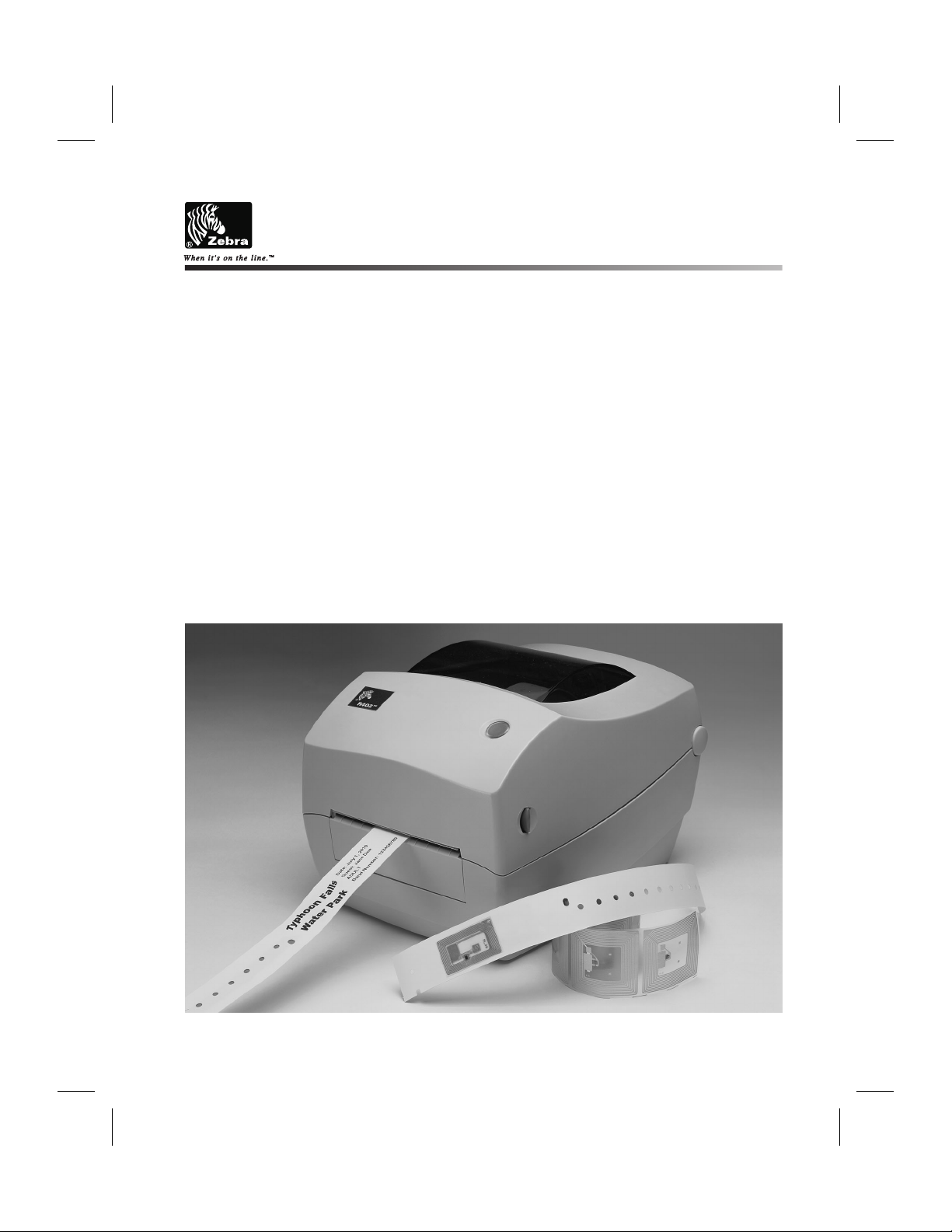
Thank you for choosing the Zebra®R402™Printer, a high-quality thermal
transfer on-demand printer with RFID capability manufactured by the
industry leader in quality, service, and value—Zebra Technologies
Corporation. For over 25 years, Zebra Technologies Corporation has
provided customers with the highest caliber of products and support.
This manual provides all of the information you will need to operate your
printer on a daily basis. RFID specific ZPL II commands are contained in
this manual. To create label formats, refer to the ZPL II Programming
Guide (part # 46530L). This guide is available by contacting your
distributor or Zebra Technologies Corporation.
NOTE: Many printer settings may also be controlled by your printer’s
driver or label preparation software. Refer to the driver or
software documentation for more information.
The Zebra R402 printer, when connected to a host computer, functions as a
complete system for printing and encoding “smart” labels, tickets, and tags.
Page 10
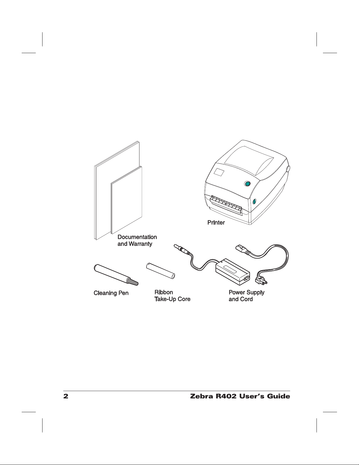
What’s in the Box?
Save the carton and all packing materials in case you need to ship or store
the printer later. After unpacking, make sure you have all parts. Follow the
procedures for inspecting the printer to familiarize yourself with printer
parts so you can follow the instructions in this book.
Page 11
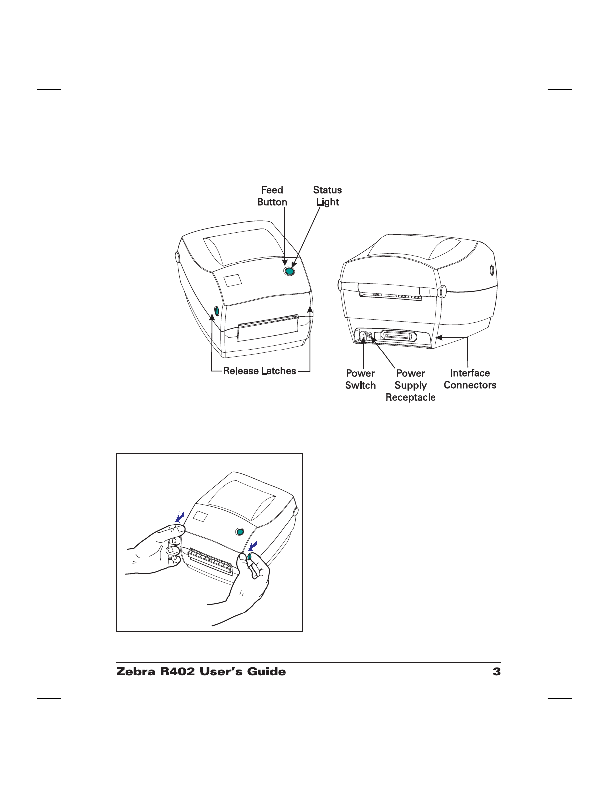
Inspecting the Printer
Look at the outside of the printer and make sure that all parts are present.
Opening the printer
To access the media compartment, you
must open the printer.
Pull the release levers towards you and lift
the cover.
Page 12
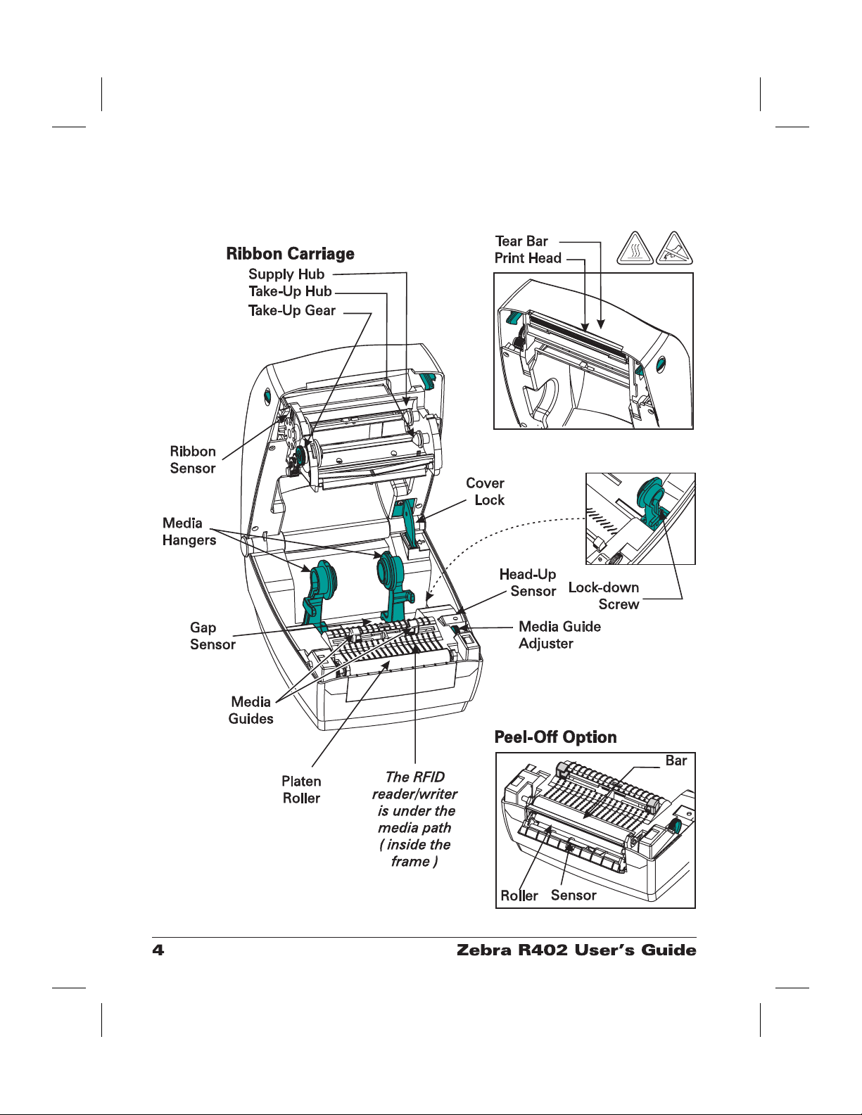
INSPECTING THE PRINTER (continued)
After opening the printer, check the media compartment.
Page 13
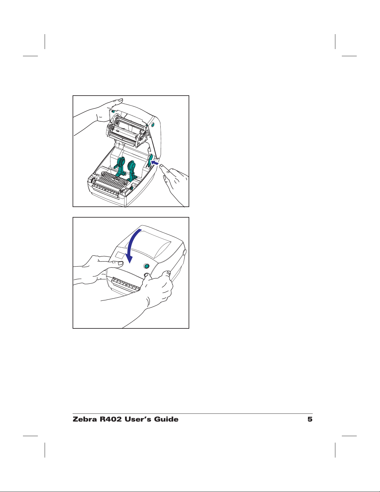
Closing the printer
Hold the top cover and press the cover
lock to release.
Lower the top cover. The ribbon carriage
automatically folds up into place.
Press down until the cover snaps closed.
Page 14

Reporting Damage
If you discover damage or missing parts:
■
Immediately notify and file a damage report with the shipping company.
Zebra Technologies Corporation is not responsible for any damage
incurred during shipment of the printer and will not cover the repair of
this damage under its warranty policy.
■
Keep the carton and all packing material for inspection.
■
Notify the authorized reseller
Page 15

This section describes how to set up your printer for the first time and use
the most common operating procedures for loading media in tear-off mode
and loading ribbon.
Modes of Printing
You can operate this printer in two different modes: tear-off or peel-off.
■
Standard tear-off mode allows you to tear off each label (or a strip of
labels) after it is printed.
■
In optional peel-off mode, the backing material is peeled away from the
label as it is printed. After this label is removed, the next one is printed.
The printer typically uses roll media, but you can use fan-fold media as
well.
For procedures to use optional modes and features, refer to the Operation
and Options section.
Getting Started
Page 16
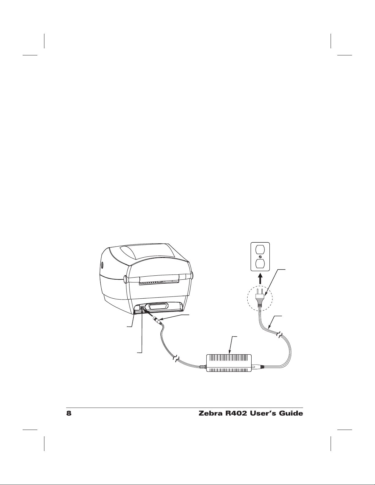
Attaching Power Supply
y
Check the power supply to make certain it is appropriate for your input
voltage.
Warning: Use the Zebra-supplied power supply that came
with your printer.
Never operate the printer and power supply in
an area where they can get wet. Serious
personal injury could result!
1. Make sure the power switch is in the off position (down).
2. The DC power supply has a barrel connector on one end that must be
inserted into the power supply receptacle on the back of the printer.
3. Insert the separate AC power cord into the power supply.
4. Plug the other end of the cord into an appropriate AC electrical outlet.
Power
Switch
Power
Supply
Receptacle
Barrel
Connector
Plug
Vari es b
Country
AC
Power
Cord
Power
Supply
Page 17

Loading Roll Media
When you load media, you must place the roll on the media hangers and
then adjust the media guides.
Placing the Roll in the Media Compartment
Whether your roll media is inside or
outside wound you load it into the printer
the same way.
1. Open the printer. Remember that you
need to pull the release levers toward
the front of the printer.
2. Remove the outside length of media.
During shipment, the roll may become
dirty when handled or dusty when
stored. Removing the outside length
avoids dragging adhesive or dirty
media between the print head and
platen.
3. Separate and hold open the media
hangers.
4. Orient the media roll so that its
printing surface will be up as it passes
over the platen.
5. Lower the roll between the hangers
and close them onto the core.
Page 18
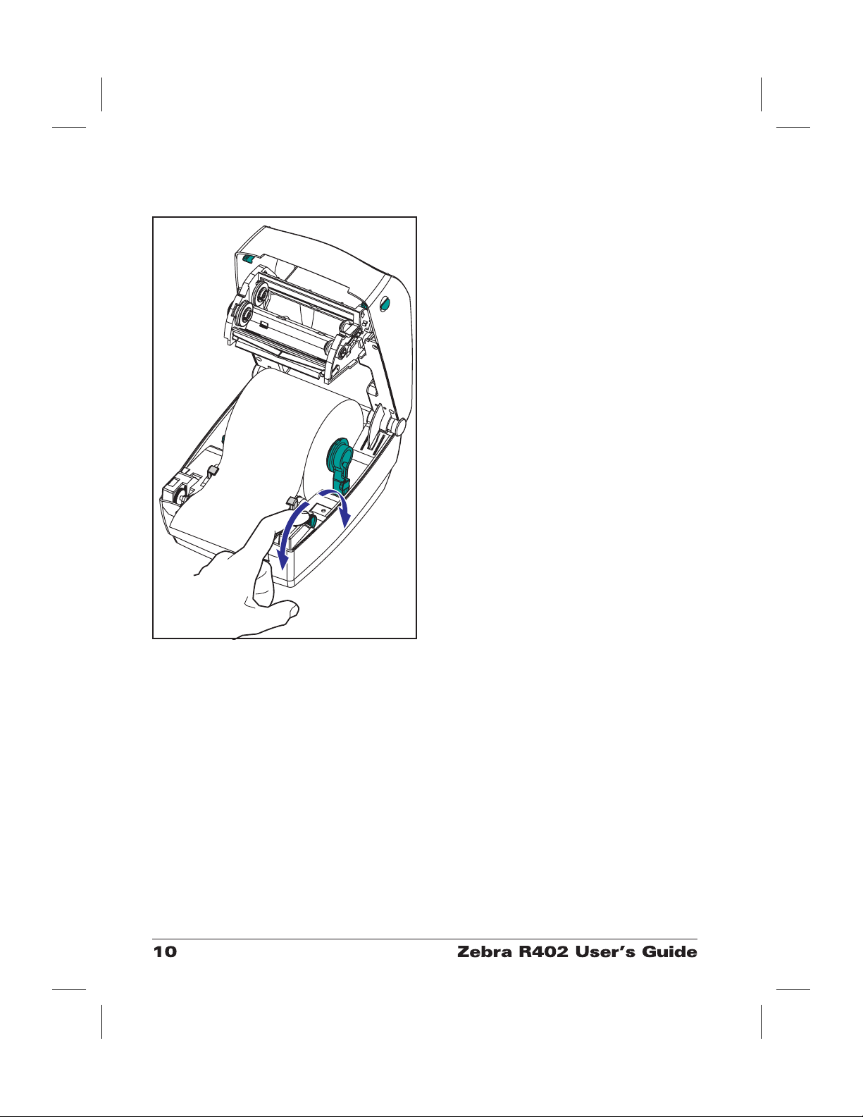
Adjusting the Guides
The adjustable guides direct the media
toward the platen and print head.
1. Open the media guides by turning the
guide adjuster knob to the rear.
2. Thread the media through the guides.
3. Close the media guides by turning the
guide adjuster knob to the front. They
should just touch, but not restrict, the
edges of the media.
4. Unless you need to load ribbon, close
the top cover. Remember that you
need to release the cover lock, lower
the top cover, and press down until the
latches snap into place.
Page 19
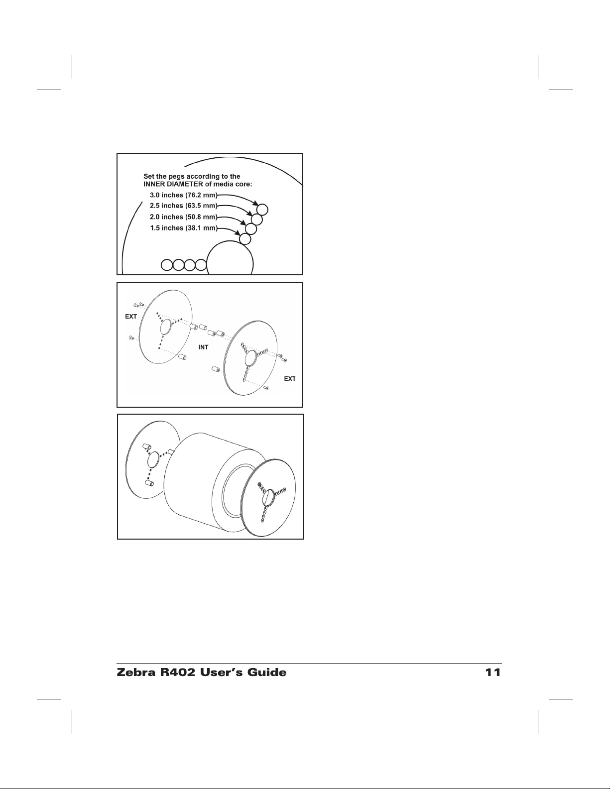
Using the Optional Media Adapter Plates
If your media roll has a larger diameter
core, you can use an accessory (part
number 105810-002) to adapt the core to
the media holders.
1. Note which position will fit the
diameter of the roll core.
2. On the left side plate, align the pegs
with the screws and use a small
Phillips driver to tighten them.
3. On the right side plate, align the pegs
with the screws and use a small
Phillips driver to tighten them.
4. Align the plates so that the pegs hold
the roll core and press together.
5. Place the roll into the media
compartment.
Page 20
Loading Ribbon
You must use thermal transfer media (accepts wax and/or resin transferred
off a ribbon) when you use a ribbon. When loading ribbon, you install the
supply and take-up rolls, then tighten the ribbon on the carriage.
Install the Ribbon Supply Roll
Before following these steps, prepare the
ribbon by removing its wrapping and
pulling its adhesive strip free.
1. Thread the ribbon through the
carriage.
2. Press the right side onto the supply
hub.
3. Align the notches on the left side and
mount onto the spokes of the left hub.
Install the Take-Up Core
1. Press the right side onto the take-up
hub.
2. Align the notches on the left side and
mount onto the spokes of the left hub.
You can find your first ribbon take-up
core in the packing box. Subsequently,
use the empty supply core to take up the
next roll of ribbon.
Page 21
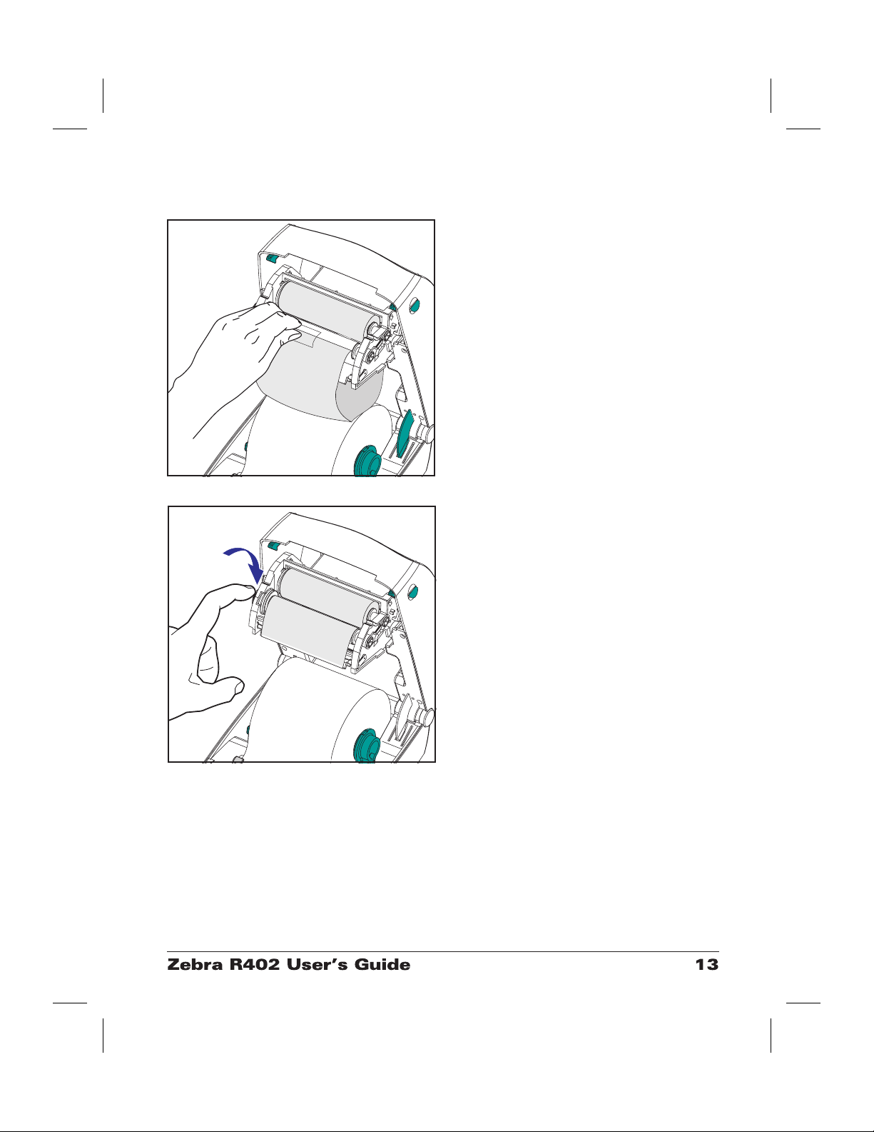
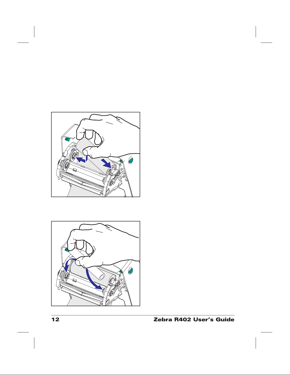
Attach and Tighten the Ribbon
You must align the ribbon so that it will
be taken straight onto the core.
1. Attach the ribbon to the take up core.
Use the adhesive strip on new rolls;
otherwise, use tape.
2. Turn the ribbon take-up gear
counter-clockwise (top moves toward
rear) to remove slack from the ribbon.
3. Close the top cover. Remember that
you need to release the cover lock,
lower the top cover, and press down
until the latches snap into place.
Page 22

Auto Calibration
NOTE: If you are using pre-printed labels, pre-printed label backing, or
continuous media, see “Manual Calibration” on page 49.
An auto calibration is performed when the printer is turned on (if media is
loaded) or after a media error is cleared. When it is auto calibrating, the
printer sets the sensor levels for, and determines the length of, the label you
are using.
If the status light flashes red, refer to “Manual Calibration” on page 49.
Page 23

Operator Controls
Power Switch
Press up to turn ON or down to turn OFF the printer.
CAUTION: The power should be turned off before connecting or
disconnecting the communications and power cables.
Feed Button
Forces the printer to feed one blank label.
Takes the printer out of a “pause” condition. (The printer is put into
“pause” by either a ZPL II command or an error condition.) See “What the
Status Light is Telling You” on page 43.
Use the Feed button for printer setup and status (see “Feed Button Modes”
on page 52).
Status Light
Functions as a printer operational indicator (see “What the Status Light is
Telling You” on page 43).
Page 24

Printing a Test Label
SCO
Before you connect the printer to your computer, make sure that the printer
is in proper working order. You can do this by printing a configuration
label.
1. Make sure the media is properly loaded and the top cover of the printer
is closed. Then, turn the printer power on if you have not already done
so.
2. When the status light is solid green, press and hold the feed button until
the status light flashes once.
3. Release the feed button. A configuration label will print.
If you cannot get this label to print, refer to Troubleshooting on page 43.
PRI NTER CONFI GURATI ON
Zebr a Technol ogi es
ZTC R402- 200dpi
................
+1 0 DARKNESS
...............
+000 TEAR OFF
...........
TE AR OFF PRI NT MODE
NON- CONTI NUOUS MEDI A T YPE
................
WEB SENSOR TYPE
THERMAL- TRANS. PRI NT METHOD
104 0/ 8 MM PRI NT WIDTH
...............
1233 LABEL L ENGTH
22. 0I N 557MM MAXI MUM LENGTH
..............
38400 BAUD
.............
8 BITS DATA BITS
...............
NONE PARI TY
...........
XON/ XOF F HOST HANDSHAKE
...............
NONE PROT OC OL
................
000 NETWORK I D
NORMAL MODE COMMUNI CAT I ONS
...........
< ~ > 7EH CONT ROL P R E F I X
...........
<^ > 5 EH FORMAT PREFI X
...........
<, > 2 CH DEL I MI TER CHAR
.............
ZPL I I ZPL MODE
...............
FEED MEDI A POWER UP
...............
FEED HEAD CLOSE
............
DEFAULT BACKFEED
...............
+0 2 0 LABEL TOP
..............
+0000 LEFT POSI TI ON
................
029 WEB S.
................
068 MEDI A S.
................
050 RI BBON S.
................
050 MARK S.
................
0 0 1 MA R K MED S.
.................
CS MODES ENABL E D
.................
. . MODES DI SABLED
832 8/ MM FULL RESOLUTI ON
SP. 814. B <- FI RMWARE
V2.2.6.98.C HARDWARE I D
CUSTOMI ZED CONFI GURATI ON
1024.............R: RAM
0000.............B: MEMORY CARD
0768.............E: ONBOARD FLASH
...............
NONE FORMAT CONVERT
...............
NONE OPTI ON
...............
NONE ZEBRA NET I I
AUT O DETE CT RF I D TA G TYPE
oem- 400: Ver . 2. 00 RFI D VERSI ON
FI RMWARE I N THISPRI NTER I
.....
.....
.........
.....
........
......
.....
........
.........
........
PYRIGHTE D
Page 25

Hooking Up the Printer and Computer
This printer comes with a bidirectional parallel data interface. You must
supply the required interface cable for your application.
CAUTIONS:Keep the power switch in the OFF position when
attaching the interface cable.
The power supply barrel connector must be inserted
into the power supply receptacle on the back of the
printer before connecting or disconnecting the com
munications cables.
-
This printer complies with FCC “Rules and Regula
tions,” Part 15, for Class B Equipment, using fully
shielded six-foot data cables. Use of longer cables or
unshielded cables may increase radiated emissions
above the Class B limits.
Parallel Interface Requirements
The required cable (IEEE 1284-compliant is recommended) must have a
standard 36-pin parallel connector on one end, which is plugged into the
parallel port located on the back of the printer. The other end of the parallel
interface cable connects to the printer connector at the host computer.
For pinout information, refer to page 57.
Interface Cable Requirements
Data cables must be of fully shielded construction and fitted with metal or
metalized connector shells. Shielded cables and connectors are required to
prevent radiation and reception of electrical noise.
To minimize electrical noise pickup in the cable:
Keep data cables as short as possible (6’ [1.83 m] recommended).
-
Do not tightly bundle the data cables with power cords.
Do not tie the data cables to power wire conduits.
Page 26

Communicating with the Printer
When using the parallel port, typically there is no setup is required once the
cable is plugged in. If you should encounter any problems, consult the
user’s guide that came with your computer.
Adjusting the Print Width
Print width must be calibrated when:
■
You are using the printer for the first time.
■
There is a change in the width of the media.
Print width may be set by way of the five-flash sequence in “Feed Button
Modes” (see page52) or refer to the Print Width (^PW) command (consult
your ZPL II Programming Guide).
Adjusting the Print Darkness
The relative darkness setting is controlled by either the six-flash sequence in
“Feed Button Modes” (see page 52) or the Set Darkness (~SD) ZPL II
command (follow the instructions in the ZPL II Programming Guide).
Adjusting the Print Speed
Print quality is affected by print speed and the media you are using. Only
by experimenting will you find the optimal mix for your application.
If you find that the print speed needs to be adjusted, refer to the Print Rate
(^PR) command in the ZPL II Programming Guide.
Page 27

Operation & Options
This section helps you get the most from your printer.
You must use programming to control many of the printer’s functions. A
few examples:
■
The ~JL command controls label length.
■
The ^XA^MTD^XZ command changes the printing mode to direct
thermal; the ^XA^MTT^XZ command changes the printing mode to
thermal transfer.
■
The ^XA^JUS^XZ command saves the new settings to flash memory.
For detailed information about creating labels using ZPL II, refer to the ZPL
II Programming Guide or visit our web site at www.zebra.com.
To improve print quality, changing both print speed and density may be
required to achieve the desired results. Your application’s printer driver
provides control of the speed and heat (density).
Thermal Printing
The print head becomes hot while printing. To protect from damaging the
print head and risk of personal injury, avoid touching the print head. Use
only the cleaning pen to perform maintenance.
The discharge of electrostatic energy that accumulates on the surface of the
human body or other surfaces can damage or destroy the print head or
electronic components used in this device. You must observe static-safe
procedures when working with the print head or the electronic components
under the top cover.
You must use the correct media for the type of printing you require. When
printing without a ribbon, you must use direct thermal media. When using
ribbon, you must use thermal transfer media. The printer’s ribbon sensor
detects motion of the supply spindle.
Page 28

Replacing Supplies
If labels or ribbon run out while printing, leave the printer power on while
reloading (data loss results if you turn off the printer). After you load a new
label or ribbon roll, the printer flashes double-green until you press the Feed
button to restart .
Always use high quality, approved labels, tags and ribbons. If adhesive
backed labels are used that don’t lay flat on the backing liner, the exposed
edges may stick to the label guides and rollers inside the printer, causing the
label to peel off from the liner and jam the printer. Permanent damage to the
print head may result if a non-approved ribbon is used as it may be wound
incorrectly for the printer or contain chemicals corrosive to the print head.
Approved supplies can be ordered from your dealer.
Adding a New Transfer Ribbon
If ribbon runs out in the middle of a print job, the indicator lights orange
and the printer waits for you to add a fresh roll.
1. Keep the power on as you change ribbon.
2. Open the top cover, then cut the used ribbon so you can remove the
cores.
3. Load a new ribbon roll. If necessary, review the Ribbon Loading steps.
4. Close the top cover.
5. Press the Feed button to restart printing.
Replacing a Partially Used Transfer Ribbon
To remove used transfer ribbon, perform the following steps.
1. Cut the ribbon from the take-up roll.
2. Remove the take-up roll and discard used ribbon.
3. Remove the supply roll and tape the end of any fresh ribbon to prevent
it from unwrapping.
When reinstalling a partially used supply roll, tape the cut end onto the
empty take-up roll.
Page 29

Printing in Peel-Mode
ON OFF
The optional dispenser allows you to print
in “peel-mode” where the label backing
follows a different path and the labels are
presented one at a time for subsequent
placement.
Before using peel-mode, you must send
the programming commands
^XA ^MMP ^XZ
^XA ^JUS ^XZ
to the printer. Refer to your ZPL II
Programmer’s Manual.
1. Remove several labels from the
backing material.
2. Open the top cover.
3. Open the dispenser door.
4. Switch on the label-taken sensor.
5. Insert the backing in front of the peel
bar and behind the peel roller.
6. Close the dispenser door.
7. Close the top cover.
8. Press the Feed button to advance the
label.
During the print job, the printer will peel
off the backing and present a single label.
Take the label from the printer so it will
print the next label.
Page 30

Printing on Fan-Fold Media
Printing on fan-fold media requires you to
set both the media hangers and the media
guides in position.
Lock-down
Screw
1. Open the top cover.
2. With a sample of your media, adjust
the media hangers to the width of the
media. The hangers should just touch,
but not restrict, the edges of the
media.
3. Tighten the screw using a small
Phillips driver #1.
4. With a sample of your media, adjust
the guides to the width of the media.
The guides should just touch, but not
restrict, the edges of the media.
5. Insert the media through the slot at the
rear of the printer.
6. Run the media between the hangers
and guides.
7. Close the top cover.
Page 31

RFID Guidelines
The Zebra R402 Smart Label Printer and Encoder serves as dynamic tool
for both printing and programming smart labels, tickets and tags. Smart
labels are usually made from two components, media and a RFID (radio
frequency identification) transponder. The media will usually be comprised
of synthetic- or paper-based material that can be printed upon using direct
thermal or thermal transfer printing techniques. The media is typically
made from the same materials and adhesives standard a non-RFID barcode
printer would use. The second component of smart label is the transponder,
sometimes known as the RFID tag. The transponder is usually comprised
of an antenna coil that is bonded to an integrated circuit (IC) chip. The IC
contains the RF drivers, coders, decoders and memory. At a minimum,
RFID tags have memory that can be read, while the vast majority also have
memory that can be programmed by the user as well.
Page 32

The communication between the RFID tag and R402 printer is established
when the transponder lines up with the printer’s antenna. Note that
transponder position, prior to encode/decode, is critical. The optimal
transponder position varies with antenna coil size and type of RFID IC
used. It is important to use media and tags that have been specifically
designed for use in the R402. Failure to do so may result in the
inability to read or program the embedded RFID tags.
Printing and programming of smart labels in handled through the use of
Zebra's printer programming language, ZPL. The printer segments the
received ZPL's RFID and non-RFID related commands. The R402 will
execute the RFID commands first, followed by the others (like the printing
commands for barcodes or human readable text). Each transponder has
blocks of addressable memory that are written to and read from through
ZPL commands. Many transponders also contain a pre-programmed unique
ID/serial number. The ZPL commands also provide for exception handling,
such as setting the number of read/write retries before declaring the
transponder defective. If an RFID tag is declared defective (fails to
program correctly or cannot be detected) the printer ejects it and prints the
word "void" across the entire label. This process will continue for two more
RFID tags using the same data and format, assuming the problems persist.
After the third tag is ejected the printer removes the customer format from
the print queue, and proceeds with the next format (if one exists in the
buffer).
Supported Transponders
The R402 supports several transponder types:
■
Texas Instruments Tag-it™
■
Philips I•Code
■
Inside Technologies Picotag® 2K
■
ISO 15693
Page 33

Texas Instruments Tag-it™ Transponders
Texas Instruments transponders are high frequency (13.56MHz) RFID
devices. Each transponder has 256 bits of memory. Data is segmented into
4 byte (32 bit) blocks that are uniquely addressable, for a total of 8 blocks.
Each memory block is lockable using the write protect function during the
writing process.
Texas Instruments Tag-it™ Blocks
Block # Description Bytes
0 User Data
1 User Data
2 User Data
3 User Data
4 User Data
5 User Data
6 User Data
7 User Data
32 User
Page 34

Philips I•Code Transponders
Philips I•Code transponders are high frequency (13.56MHz) RFID devices.
Each transponder has 512 bits of memory. Data is segmented into 4 byte
(32 bit) blocks that are uniquely addressable for a total of 16 blocks. Each
memory block is lockable using the write protect function during the
writing process. The first two blocks of data (block 0 and 1) are
pre-programmed, non-changeable, and are used for storage of a unique 64
bit serial number. The next two blocks (blocks 2 and 3) are used for storage
of configuration information; block 4 is used for family or application
identification and blocks 5 to 15 are free for user application use.
If you are using these transponders for your own use, and don’t require
universal special function or family codes, then you can program blocks 3
through 15.
Block # Description Bytes
0 Serial Number (write protected)
1 Serial Number (write protected)
2 Write Protect Block (Caution*)
3 Special Function Block
4 Family Code
5 User Data
6 User Data
7 User Data
8 User Data
9 User Data
10 User Data
11 User Data
12 User Data
13 User Data
14 User Data
15 User Data
Philips I•Code Blocks
8 Optional
40 User
* The bits in block 2 determine the write access conditions for itself and
each of the remaining blocks. You can leave blocks 2 through 15 open or
you can write-protect them. Write-protected blocks (included block 2) can
never be written to from the moment they are locked
Page 35

Inside Technologies Picotag® Transponders
Inside Technologies Picotag® transponders are high frequency (13.56MHz)
RFID devices. Each transponder has 2048 bits of memory. Data is
segmented into 8 byte (64 bit) blocks that are uniquely addressable for a
total of 31 blocks. Blocks 6 to 12 are lockable using the write protect
function during the writing process. The first block of data (block 0) is
pre-programmed and is used for storage of a unique 64 bit serial number.
The next two blocks (blocks 2 and 3) are used for storage of configuration
information; blocks 3 to 31 are free for user application use.
Inside Technologies Picotag® 2K
Block
0 Serial Number (64 bits)
1
2 Application Issuer Area
3
5
6
7
8
9
10
11
12
13
31
0123456 7
FFh
Application
16-bit OTP
Byte number within a block
Block
Area
Block Write Lockable Application Area
Write
Lock
Application Area4
Application Area...
Tun-
ing
Cap
1Fh
E.A.
S.
Fuses
Page 36

ISO-15693 Transponders
ISO-15693 is an international standard for 13.56 MHz RFID devices. As
this is a public standard, tags and integrated circuits may be produced by a
wide variety of manufacturers. The current standard stipulates that
manufacturers may configure memory in various ways ( up to 256 blocks
comprising a block size up to 256 bits (32 bytes)). The standard also
stipulates that a manufacturer may, or may not, use the recommend methods
of reading and writing to the tag as stipulated in the standard. For these
reasons, the R402 may not be compatible with every manufacturers
ISO-15693 transponders. Contact your technical support representative for
the latest list of supported ISO-15693 transponders.
Page 37

ZPL II Commands for RFID
^WT – Write Tag
The format for the ^WT instruction is:
where
^WT = Write Tag command
b = Block Number
Default value: 0
Other values: 1 to n, where n is the maximum number of
blocks for the tag
This is the starting block number. If the user sends more than a block of
data it will overflow into the next block. If the user overflows the block and
subsequent blocks cause errors (write protects, beyond range, etc.), the
write will be aborted, but blocks already written will not revert to original
contents. It’s up to the caller to ensure blocks aren’t accidentally
overwritten.
r = Retries
Default value: 0
Other values: 1 to 10, number of retries
m = motion
Default value: 0 (Feed label after writing)
Other value: 1 (No Feed after writing, other ZPL may cause
a feed)
^WTb,r,m,w,s
w = Write protect
Default value: 0 (NOT write protected)
Other value: 1 (Write protect)
s = Special mode
Reserved
Page 38

^RT – Read Tag
The format for the ^RT instruction is:
where
^RT = Read Tag command
# = Number to be assigned to the Field
Default value: 0
Other Values: 1 to 9999
b = Starting Block Number
Default value: 0
Other values: 1 to n, where n is the maximum number of
blocks for the tag
n = Number of blocks to read
Default value: 1
Other values: 2 to n, where n is maximum number of blocks
minus starting block number. In other words, if the tag has 8
blocks (starting with block 0) and you’re starting with block 6,
n can be 2. This would give you block 6 and block 7
information.
f = Format
Default value: 0 ASCII
Other values: 1 Hexadecimal
^RT#,b,n,f,r,m,s
r = Retries
Default value: 0
Other values: 1 to 10, number of retries
m = motion
Default value: 0 (Feed label after writing)
Other value: 1 (No Feed after writing, other ZPL may cause
a feed)
s = Special Mode
Default value: 0
Other values: 1 to 255, to specify more detailed mode control.
Page 39

^RT – Read Tag (continued)
Example: This reads a block from a tag, and prints it on a label:
^XA
^FO20,120^A0N,60^FN1^FS
^FO20,100^A0N,20^FN2^FS
^RT1,0,7,3,0,5,0,0^FS
^RT2,0,2,2,0,5,0,0^FS
^XZ
The first ^RT command automatically detects the tag type, starting at block
7, reads three blocks of data in ASCII format. It will retry the command 5
times if necessary. A “void” label will be generated if the read is
unsuccessful after ‘r’ retries. The data read will go into the ^FN1 location
of the recalled format.
The second ^RT command automatically detects the tag type, string at
block 2, reads two blocks of data in ASCII format. It retries up to 5 times.
The data read will go into the ^FN2 location of the recalled format.
The data can be sent back to the host via the ^HV command.
Page 40

^RS – RFID Setup
The format for the ^RS instruction is:
where
t = tag type
Default value: 0 –NONE (No tags available)
Other values:
1- Auto detect (automatically determine the
tag type, by querying the tag)
2- Texas Instruments Tag-it™ tags
3- Philips I•Code tags
4- Inside Technologies Picotag® 2K
5- ISO 15693 tag*
# = read/write position of transponder in rows of dots
Set to 0 (zero) to not move the media.
Default value: Label length minus eight dot rows
(one millimeter)
Other values: 0 (zero) to label length
Use caution when using this function in combination with ^RI (reading the
unique ID number) or ^RT (reading tag data). Problems can occur if the
data read from the tag is going to be printed on the label. Any data read
from the transponder must be positioned to be printed above the read/write
position. Failure to do this will prevent read data from being printed on the
label, ticket or tag.
^RSt,#
* ISO-15693 is an international standard for 13.56 MHz RFID devices. As
this is a public standard, tags and integrated circuits may be produced by a
wide variety of manufacturers. The current standard stipulates that
manufacturers may configure memory in various ways ( up to 256 blocks
comprising a block size up to 256 bits (32 bytes)). The standard also
stipulates that a manufacturer may, or may not, use the recommend
methods of reading and writing to the tag as stipulated in the standard. For
these reasons, the R402 may not be compatible with every manufacturers
ISO-15693 transponders. Contact your technical support representative for
the latest list of supported ISO-15693 transponders.
Page 41

^RI – RFID Get Tag Unique ID
The format for the ^RI instruction is:
where
n = field number to store the unique ID
The unique ID will be read from the tag and available to
print or return to the host computer.
The example below reads the unique ID/serial number from a tag, and prints
it on a label:
^XA
^FO100,100^A0N, 60^FN0^FS
^RI0^FS
^FD ^FS
^XZ
^RIn
Page 42

Sample of RFID Programming
ZPL IITMis Zebra Technologies Corporation’s Zebra Programming
Language II label design language. ZPL II lets you create a wide variety of
labels from the simple to the very complex, including text, bar codes, and
graphics.
This section is not intended as an introduction to ZPL II. If you are a new
ZPL II user, order a copy of the ZPL II Programming Guide (part# 46530L)
or go to the internet address http://support.zebra.com and select the
Documentation Button to download the guide.
For your programming, do the following:
1. Set up the printer and turn the power on.
2. Use any word processor or text editor capable of creating ASCII-only
files (ex: Microsoft Word® and save as a .txt file) and type in the label
format exactly as shown in the sample label format that follow.
3. Save the file in a directory for future use. Use the “.zpl” extension.
4. Copy the file to the printer.
From the DOS command window, use the “COPY” command to send a
file to the Zebra printer. For example, if your file name is
then type, “COPY FORMAT 1.ZPL XXXX”, where “XXXX” is the
port to which your Zebra printer is connected, for example, “LPT1.”
format1.zpl
5. Compare your results with those shown. If your printout does not look
like the one shown, confirm that the file you created is identical to the
format shown, then repeat the printing procedure. If nothing prints,
refer to the “Getting Started” section to make sure your system is set up
correctly, otherwise refer to the “Troubleshooting and Diagnostics”
section.
Page 43

Line # Type this label format Resulting printout
1.
2.
3.
4.
5.
6.
7.
^XA
^WT6^FDZebra^FS
^FO100,100^A0n,60^FN0^FS
ZEBRA
^FO100,200^A0n,40^FN1^FS
5A65627261000000
^RT0,6,2^FS
^RT1,6,2,1
^XZ
Line 1 Indicates start of label format.
Line 2 Writes the data “Zebra” to block 6 for the tag (one byte will
spill into block 7, since we have 4 bytes/block.
Line 3 Print field number ‘0’ at location 100,100.^FN0 is replaced
by what we read on line #5.
Line 4 Print field number ‘1’ at location 100,200. ^FN1 is replaced
by what we read on line #6.
Line 5 Read Tag into field number 0, starting at block 6, lasting for 2
blocks in ASCII format (default).
Line 6 Read Tag into field number 1, starting at block 6, lasting for 2
blocks in hexadecimal format.
Line 7 End of label format.
Page 44

Page 45

Cleaning
Use only the cleaning agents indicated. Zebra Technologies Corporation
will not be responsible for damage caused by any other cleaning materials
used on this printer.
Printer Part Method Interval
Print head
Platen roller
Peel bar
Tear bar
Exterior Water-dampened cloth
Interior Brush or air blow
Maintenance
After allowing the print head to cool for approximately
one minute, use 70% isopropyl alcohol on a cotton
swab to clean the print elements from end to end (the
print elements are located in the thin gray line on the
print head). NOTE: You do not have to turn off the
printer to do this.
If print quality has not improved after performing this
procedure, try cleaning the print head with Save-a-Print
Head cleaning film. This specially coated material
removes contamination buildup without damaging the
print head. Call your authorized reseller for more
information.
Manually rotate the platen roller. Clean it thoroughly
with 70% isopropyl alcohol and a cotton swab or
lint-free cloth.
Clean it thoroughly with 70% isopropyl alcohol and a
cotton swab.
Clean it thoroughly with 70% isopropyl alcohol and a
cotton swab.
After every
five rolls of
media
As needed
Lubrication
No lubricating agents of any kind should be used on this printer! Some
commercially available lubricants, if used, will damage the finish and the
mechanical parts inside the printer.
Page 46

Parts List
ITEM DESCRIPTION
1 Latch Assembly 105910-052
2 Feed Switch/Sensor Assy (set of 3) 105910-128
3 Upper Cover Support (set of 3) 105910-066
4
5 Head Up Sensor 105910-129
6 Gap/Blackline Sensor PCBA (set of 3) 105910-054
7 Platen Kit (standard set of 3) 105910-055
8
10 Rubber Foot Kit (set of 24) 105910-007
11 Main Control PCBA (RFID) 105910-133
12 Bottom Frame Assy 105910-130
13 Upper Cover Assy 105910-131
14 Ribbon Out Sensor (set of 3) 105910-134
15 Ribbon Carriage w/o printhead 105910-132
Not
Shown
Manuals
Print Head Assy - 4” TLP
Print Head Cable Assy.
Front Bezel (standard set of 10)
Front Bezel, Dispenser (single)
Motor (set of 2)
Power Supply, 100V-240V
Power Cord, U.S. 120V IEC320C13 (set of 5)
PCBA, RFID Reader
PCBA, Antenna, Type 2
Ribbon Core, 4” (set of 50)
Accessory, Media Adapter Plates
User’s Manual, R402
ZPL II Programmer’s Manual
PART
NUMBER
105910-053
105910-065
105910-057
105910-022
105910-051
105950-043
105950-014
105903-135
105950-136
105903-053
810059-001
980389-001
46530L
Page 47

14
15
1
2
13
11
12
3
4
5
6
8
7
9
10
Page 48

Replacing the Print Head
In the event you need to replace the print
head, make sure your work area is
prepared by protecting against static
discharge. Your work area must be
static-safe and include a properly
grounded conductive cushioned mat to
hold the printer a conductive wrist strap
for yourself.
Removal
Before following the steps in this
procedure, open the printer by pulling the
release latches forward then lifting the top
cover. Remove any ribbon from the
carriage.
1. Grasp the print head spring and pull it
to the left; then, slide it free of the
carriage.
2. Use the spring to pry the print head
clip off the right side of the carriage.
3. Pull the print head and bracket
forward.
4. Use a #2 Phillips driver to remove the
screw that holds the ground wire.
5. Unplug both bundles of print head
wires from their connectors.
Page 49

REPLACING THE PRINT HEAD (Continued)
Assembly
The new print head comes with the clip
and ground screw attached.
1. Align the print head and bracket to
2. Attach the ground wire and secure it
3. Insert the bracket pegs into the left
4. Align the right side of the bracket and
Cleaning the Print Head
plug the left and right connectors into
the black and white wire bundles.
with the screw. Use a #2 Phillips
driver to tighten it.
side of the carriage.
insert the print head clip through the
right side of the ribbon carriage into
the bracket.
5. Slip the left end of the print head
spring into the left side of the ribbon
carriage; then slide the right end into
the other side. The angle of the “v”
fits into the indent on top of the print
head bracket.
6. Clean the print head with the cleaning
pen.
Reload media and ribbon. Plug in the
power cord, turn on the printer and run an
automatic or manual calibration to ensure
proper function.
Page 50

Page 51

Troubleshooting
What the Status Light is Telling You
Status LED
Condition and Color
Off Off 1
Solid Green On 2
Flashing Yellow Stopped 3
Flashing Green Normal Operation 4
Flashing Red Stopped 5
Double Flashing Green Paused 6
Solid Yellow Various 7
Alternately Flashing Green and Red Needs Service 8
Printer
Status
Resolutions
1. The printer is not receiving power.
For a Resolution,
Refer to number:
■
Have you turned on the printer power?
■
Check power connections from the wall outlet to the power supply, and
from the power supply to the printer.
2. The printer is on and in an idle state.
■
No action necessary.
Page 52

3. The printer has failed its power on self test (POST).
■
If this error occurs right after you turn on the printer, contact an
authorized reseller for assistance.
There is a shortage of memory.
■
If this error occurs after you have been printing, turn the printer power
off and on. Then, resume printing.
4. The printer is receiving data.
■
As soon as all of the data has been received, the status LED will turn
green; then, the printer will automatically resume operation.
5. Either the media or ribbon is out.
■
Load a roll of media, following the instructions in “Loading the Media”
on page 9. Then, press the feed button to resume printing.
■
Load a roll of ribbon, following the instructions in “Loading the Ribbon”
on page 12. Then, press the feed button to resume printing.
The print head is open.
■
Close the top cover. Then, press the feed button to resume printing.
6. The printer is paused.
■
Press the feed button to resume printing.
Page 53

7. The print head is under temperature.
■
Continue printing while the print head reaches the correct operating
temperature.
The print head is over temperature.
■
Printing will stop until the print head cools to an acceptable printing
temperature. When it does, the printer will automatically resume
operation.
8. FLASH memory is not programmed.
■
Return the printer to an authorized reseller.
Page 54

Print Quality Problems
No print on the label.
■
You must use the correct media for the method of printing you require.
When printing without a ribbon, you must use direct thermal media.
When using ribbon, you must use thermal transfer media. The printer's
ribbon sensor detects motion of the supply spindle.
■
Is the media loaded correctly? Follow the instructions in “Loading the
Media” on page 9.
The printed image does not look right.
■
The print head is dirty. Clean the print head according to the
instructions on page 41.
■
The print head is under temperature.
■
Adjust the print darkness and/or print speed. Refer to the six-flash
sequence in “Feed Button Modes” on page 52, or the ^PR and ~SD
commands in the ZPL II Programming Guide.
■
The media being used is incompatible with the printer. Be sure to use
the recommended media for your application, and always use
Zebra-approved labels and tags.
There are long tracks of missing print (blank vertical lines) on
several labels.
■
The print head is dirty. Clean the print head according to the
instructions on page 41.
■
The print head elements are damaged. Replace the print head (see
“Replacing the Print Head” on page 40).
The ribbon sensor settings did not print.
■
The printer is set for direct thermal printing; use the ^XA^MTT^XZ
command to reset the printer for thermal transfer printing and calibrate
again.
Page 55

The printing does not start at the top of the label, or misprinting of
one to three labels.
■
The media may not be threaded under the media guides. Refer to
“Loading the Media” on page 9.
■
The printer needs to be calibrated. Refer to “Auto Calibration” on page
14.
■
The correct media sensor may not be activated. Manual calibration
selects the media sensing method for the labels being used (refer to the
^MN command in the ZPL II Programming Guide).
■
Verify that the Label Top (^LT) command is correctly set for your
application (consult the ZPL II Programming Guide).
A label format was sent to, but not recognized by, the printer.
■
Is the printer in pause mode? If so, press the feed button.
■
If the status LED is on or flashing, refer to “What the Status LED is
Telling You” on page 43.
■
Make sure the data cable is correctly installed.
■
A communications problem has occurred. First, make sure that the
correct communications port on the computer is selected. Refer to
“Communicating with the Printer” on page 18.
Page 56

RFID Symptoms
RFID tags generally not programmed
■
Is the printer set up correctly? Print a configuration label to verify RFID
version. See “Auto Calibration” on page 14.
■
Check if supported RFID media is loaded correctly.
VOID messages are printed across media.
■
Verify tag type is properly selected in ZPL II. Use RFID media with
supported tag type. Edit ZPL II to select proper tag type or increase
retries.
■
ZPL II is attempting to write to a non-existent block. Some tags’ blocks
are identified as 0-7. If ZPL II attempts to write to block “8,” it will fail.
■
Verify voided tag on external reader. Discard bad tags if this is a media
problem.
Nothing is printed.
■
See if the correct media is loaded or load new, fresh media.
■
See if tags can be read/programmed using other hardware.
■
Verify ZPL II RFID commands. Debug the printing program.
■
Tag is out of reach of the antenna or too close. Verify tag alignment.
■
Wrong type of tag was selected. Check ZPL II.
■
Block is write protected. Ensure that the tag is not write protected.
■
Aluminum and other metals within tag may interfere with read/write.
Make sure media meets requirements.
■
Increase the number of retries in the ZPL II commands.
■
Time out may have occurred during internal communication. Cycle
power and try printing label again.
Call a service technician if you have been unsuccessful in getting your
expected print out and data.
Page 57

Manual Calibration
Manual calibration is recommended whenever you are using pre-printed
labels (or label backing) or if the printer will not correctly auto calibrate.
1. Turn on the printer power.
2. Remove approximately 4" (102 mm) of labels from a section of backing
material. Load the media so that only the backing material is threaded
through the printer and under the print head.
3. Press and hold the feed button until the green status LED flashes once,
then twice. Release the feed button.
4. The printer will set the media sensor for the label backing being used.
After it is done making this adjustment, the roll will automatically feed
until a label is positioned at the print head.
5. A profile of the media sensor settings (similar to the example below)
will print. Upon completion, the printer will save the new settings in
memory and the printer is ready for normal operation.
6. Press the feed button. One entire blank label will feed. If this does not
happen, try defaulting (refer to the four-flash sequence in “Feed Button
Modes” on page 52) and recalibrating the printer.
NOTE: Performing a manual calibration disables the auto calibration
function. To return to auto calibration, default the printer (see the
four-flash sequence in “Feed Button Modes” on page 52).
Page 58

Troubleshooting Tests
SCO
Printing a Configuration Label
To print out a listing of the printer’s current configuration, refer to the
one-flash sequence in “Feed Button Modes” on page 52.
Recalibration
Recalibrate the printer if it starts to display unusual symptoms, such as
skipping labels. See “Auto Calibration” on page 14.
PRI NTER CONFI GURATI ON
Zebr a Technol ogi es
ZTC R402- 200dpi
................
+1 0 DARKNESS
...............
+000 TEAR OFF
...........
TE AR OFF PRI NT MODE
NON- CONTI NUOUS MEDI A TYPE
................
WEB SENSOR TYPE
THERMAL - TRANS. PRI NT MET HOD
104 0/ 8 MM PRI NT WIDTH
...............
1233 LABEL L ENGT H
22. 0I N 557MM MAXI MUM LENGTH
38400 BAUD
8 BITS DATA BITS
...............
NONE PARI TY
XON/ XOF F HOST HA NDSHA KE
...............
NONE PROT OCOL
................
000 NETWORK I D
NORMAL MODE COMMUNI CAT I ONS
< ~ > 7 E H CONT ROL PRE F I X
<^ > 5EH FORMAT PREFI X
<, > 2 CH DEL I MI T ER CHAR
ZPL I I ZPL MODE
...............
FEED MEDI A POWER UP
...............
FEED HEAD CLOSE
DEFAULT BACKFEED
...............
+0 2 0 LABEL TOP
+0000 LEFT POSI TI ON
................
029 WEB S.
................
068 MEDI A S.
................
050 RI BBON S.
................
050 MARK S.
................
0 0 1 MA R K MED S.
.................
CS MODES ENA BL ED
.................
. . MODES DI SABLED
832 8/ MM FULL RESOLUTI ON
SP. 814. B <- FI RMWARE
V2.2.6.98.C HARDWARE I D
CUSTOMI ZED CONFI GURATI ON
1024.............R: RAM
0000.............B: MEMORY CARD
0768.............E: ONBOARD FLASH
...............
NONE FORMAT CONVERT
...............
NONE OPTI ON
...............
NONE ZEBRA NET I I
AUT O DETE CT RF I D TA G TYPE
oem- 400: Ver . 2. 00 RFI D VERSI ON
FI RMWARE I N T HISPRI NTER I
.....
.....
.........
.....
..............
.............
...........
........
...........
...........
...........
.............
............
..............
......
.....
........
.........
........
PYRIGHTE D
Page 59

Resetting the Factory Default Values
Sometimes, resetting the printer to the factory defaults solves some of the
problems. Follow the four-flash sequence instructions in “Feed Button
Modes” on page 52.
Communications Diagnostics
If there is a problem transferring data between the computer and printer, try
putting the printer in the communications diagnostics mode. The printer
will print the ASCII characters and their respective hexadecimal values (a
sample is shown below) for any data received from the host computer. To
find out how, refer to the power off mode procedure in “Feed Button
Modes” on page 52.
Page 60

Feed Button Modes
Power Off Mode (Communications Diagnostics Mode)
With the printer power off, press and hold the feed button while you turn on the power. The printer
prints out a listing of its current configuration (see Figure 22). After printing the label, the printer will
automatically enter a diagnostic mode in which the printer prints out a literal representation (see Figure
23) ofall datasubsequently received. To exit the diagnostic modeand resume printing,turn off and then
turn on the printer.
Power On Modes
With theprinter power on and topcover closed, press and holdthe feed button for severalseconds. The
green status LED will flash a number of times in sequence. The explanation at the right (Action) shows
what happens when you release the key after the specific number of flashes.
Flash
Sequence
* A configuration label prints.
*
**
*
**
***
*
**
***
****
*
**
***
****
*****
*
**
***
****
*****
******
If the feed button remains pressed after a 7-flash sequence, the printer will ignore the button when it
is released.
The media sensor calibrates and a media sensor profile prints (see “Manual
Calibration” on page 49).
To reset the communication parameters. Press and release the feed button while
the LED rapidly flashes yellow and green.
For autobaud synchronization: Send a ZPL II format to the printer while the LED
rapidly flashes yellow and green. When the printer and host are synchronized, the
LED changes to solid green. NOTE: No labels will print during autobaud
synchronization.
Resets the factory defaults, auto calibrates, and saves settings into memory.
The print width calibrates. While the status LED alternately flashes green and
yellow, a series of stacking rectangles print on the label. When the rectangle prints
to the outer edges of the label, press and release the feed button. The label width
and current communication parameters will be saved into memory.
The print darkness calibrates. A series of nine samples print, starting with the
lightest and ending with the darkest image. When the desired print darkness is
achieved, press and release the feed button. The print darkness will be saved into
memory.
Action
Page 61

Appendix
All specifications are subject to change without notice.
Physical Specifications
Size 7.8 inches wide / 6.8 inches tall / 9.4 inches long (depth)
200 mm wide / 173 mm tall / 240 mm long (depth)
Weight 3.6 pounds / 1.6 kilograms
Environmental Guidelines
Operating temp. 40 to 104 degrees Fahrenheit / 5 to 40 degrees Celsius
Operating humidity 10 to 90 percent non-condensing
Storage temp. -40 to 140 degrees Fahrenheit / -40 to 60 degrees Celsius
Storage humidity 5 to 90 percent non-condensing
Electrical Autoranging external power supply
Printing Specifications
Print Density 203 dots per inch / 8 dots per millimeter
Print Speed 2 inches / 51 millimeters per second
Print Width 1.0 to 4.09 inches / 25.4 to 104 millimeters
Print Length 0.005 to 22 inches / 0.125 to 559 millimeters
Registration
Tolerance
FLASH Memory
(user available)
DRAM Memory
(user available)
Input: 100-240VAC; 50-60 Hz
Output: 20VDC; 2.5A
3 inches / 76 millimeters per second
4 inches / 102 millimeters per second
with standard memory
Horizontal: +/- 0.0591 inches (1.5 millimeters)
Vertical: +/- 0.0393 inches (1.0 millimeters)
768K
1 MB
Page 62

Media Specifications
Width 1 to 4.25 inches / 25.4 to 108 millimeters)
1 to 2.25 inches / 25.4 to 57 millimeters (tag stock)
Length 0.5 to 22 inches / 13 to 559 millimeters with standard memory
Gap 0.08 to 0.16 inch (2.0 to 4.0 millimeters)
0.118 inch / 3.0 millimeters recommended
Thickness 0.003 to 0.007 inch / 0.08 to 0.18 millimeter
Roll Size Maximum outer diameter: 5 inches (127 millimeters
Inner Core diameters: 1 or 1.5 inches (25.4 or 38 millimeters)
Optional media hangers available for larger inner core
diameters
Requirements
Transponder
Requirements
User Zebra-brand direct thermal or thermal transfer media
✔
that is outside wound. Media may be reflective (black mark)
sensing or transmissive sensing, die-cut, notched, or
continuous)
For die-cut labels, use only full auto dies.
✔
Notched media must have a 0.5 inch (13 mm) wide by 0.094
✔
inch (2.5 mm) long cutout located in the center of the roll.
✔ The reflective media black marks must be located in the
center of the roll. Mark width 0.5 inch (13 mm) centered and
perpendicular to the edge of the media; mark length 0.094
inch (2.4 mm) parallel to the bottom edge of the media.
✔ Phillips I•Code
✔ Texas Instruments Tag-It™
✔ Inside Technologies PicoTag®
✔ ISO-15693
Always thoroughly test your desired media for your specific application
before buying in large quantities.
Ribbon Specifications
Roll Size Maximum outer diameter: 1.3 inches / 33 millimeters
Length 2,900 inches / 74 meter capacity; provides 1:1 media roll to
Width At least as wide as media
Setup Ink-side out
Requirements User Zebra-brand ribbon that is outside wound.
ribbon ratios
Page 63

Font/Code Specifications
Fonts
1D Bar Codes
2D Bar Codes
Rotation Angles 0°, 90°, 180° and 270°
CG Triumvirate Bold Condensed scalable smooth (0)
✔
Zebra fonts A-H, GS, P-V
✔
IBM Code Page 850 international Symbols
✔
Codabar (supports ratios of
✔
2:1 to 3:1)
Code 11
✔
Code 128/USD 8 (supports
✔
serialization in all subsets
and UCC Case Codes)
Code 39 (supports ratios of
✔
2:1 to 3:1)
Code 93
✔
EAN 8/JAN 8
✔
EAN 13/JAN 13
✔
EAN 14/UPC-A
✔
Codeblock
✔
Code 49
✔
Data Matrix
✔
✔ MaxiCode
Zebra Programming Language (ZPL II®)
✔ Downloadable graphics, scalable and
bitmap fonts, and label formats
✔ Object copying between memory areas
(RAM and internal FLASH)
✔
Code Page 850 character set
✔
Adjustable print cache
✔
Data compression
✔
Automatic virtual input buffer
management
✔
Automatic memory allocation
✔
Format inversion
✔
Mirror image printing
✔
Four-position field rotation
0°, 90°, 180° and 270°
✔ Slew command
✔ Programmable quantity with print and
pause
✔
Communicates in printable ASCII
characters
✔
Error-checking protocol
✔
Controlled via mainframe,
mini-computer, PC, portable data
terminal
✔
In-spec OCR-A and OCR-B
✔
UPC/EAN
✔
User-programmable password
✔
Status message to host upon request
Industrial 2 of 5
✔
Standard 2 of 5
✔
Interleaved 2 of 5 (supports
✔
ratios of 2:1 to 3:1,
Modulus 10 Check Digit)
LOGMARS
✔
MSI
✔
Plessey
✔
POSTNET
✔
UPC-E
✔
UPC-EAN Extensions
✔
MicroPDG417
✔
PDF 417
✔
QRcode
✔
Page 64

Agency Approvals
The Thermal Printer Model R402, manufactured by Zebra Technologies
Corporation, complies with the applicable requirements:
Emissions and susceptibility: FCC 15.225, FCC Part 15 Class B, RSS-210, EN300-330,
✔
EN300-683, IECS-003, EN61000-3-2, EN61000-3-3.
rd
Safety: UL 1950 3
✔
Ed., CSA C22.2 No. 950-95 3rdEd., IEC950/EN60950
Options
Adjustable core diameter media holders
✔
Dispenser for “peel-off mode”
✔
Page 65

Parallel Interface Technical Information
Pin No. Description
1 NStrobe/Host Clk
2-9 Data Bits 1-8
10 nACK/PtrClk
11 Busy/Per Busy
12 PError/ACK Dat Req.
13 Select/Xflag
14 NAuto Fd/Host Busy
15 Not Used
16-17 Ground
18 +5 V @ 0.75 A Fused
19-30 Ground
31 nInit
32 NFault/nData Avail.
33-34 Not Used
35 +5 V throught 1.8 K Ohms Resistor
36 NSelectin/1284 active
The maximum current available through the interface port is not to exceed a
total of 0.75 amps.
Page 66

Page 67

Index
A
adapter plates . . . . . . . . . . . . . . . . . . . 11
agencies . . . . . . . . . . . . . . . . . . . . . . . 56
attaching power . . . . . . . . . . . . . . . . . . 8
auto calibration. . . . . . . . . . . . . . . . . . 14
B
bar codes. . . . . . . . . . . . . . . . . . . . . . . 55
barrel connector . . . . . . . . . . . . . . . . . . 8
box, contents. . . . . . . . . . . . . . . . . . . . . 2
button, feed. . . . . . . . . . . . . . . . . . . . . 15
C
cable . . . . . . . . . . . . . . . . . . . . . . . . . . 17
calibration
manual . . . . . . . . . . . . . . . . . . . . . . 49
calibration, auto . . . . . . . . . . . . . . . . . 14
cleaning . . . . . . . . . . . . . . . . . . . . . . . 37
cleaning the print head . . . . . . . . . . . . 41
closing printer. . . . . . . . . . . . . . . . . . . . 5
communicating . . . . . . . . . . . . . . . . . . 18
Communications diagnostics . . . . . . . 51
configuration label . . . . . . . . . . . . 16, 50
controls, operator . . . . . . . . . . . . . . . . 15
copyrights . . . . . . . . . . . . . . . . . . . . . . iii
cover lock . . . . . . . . . . . . . . . . . . . . . . . 4
E
environmental guidelines . . . . . . . . . . 53
F
factory defaults, resetting . . . . . . . . . . 51
Factory defaults, resetting . . . . . . . . . 52
fan-fold media . . . . . . . . . . . . . . . . . . 22
FCC . . . . . . . . . . . . . . . . . . . . . . . . . . . iii
feed button . . . . . . . . . . . . . . . . . . . 3, 15
feed button modes . . . . . . . . . . . . . . . 52
fonts . . . . . . . . . . . . . . . . . . . . . . . . . . 55
G
get tag ID command . . . . . . . . . . . . . . 33
getting started . . . . . . . . . . . . . . . . . . . . 7
guides, media . . . . . . . . . . . . . . . . . . . 10
H
holders, media . . . . . . . . . . . . . . . . . . . 4
I
I-Code. . . . . . . . . . . . . . . . . . . . . . . . . 26
inspecting printer . . . . . . . . . . . . . . . . . 3
interface . . . . . . . . . . . . . . . . . . . . . . . 17
interface connectors . . . . . . . . . . . . . . . 3
ISO-15693 . . . . . . . . . . . . . . . . . . . . . 28
D
damage, reporting . . . . . . . . . . . . . . . . . 6
defaulting the printer . . . . . . . . . . . . . 51
diagram, parts . . . . . . . . . . . . . . . . . . . 39
dispenser. . . . . . . . . . . . . . . . . . . . . . . 21
L
light, status . . . . . . . . . . . . . . . . . . . . . 15
loading media . . . . . . . . . . . . . . . . . . . . 9
loading ribbon. . . . . . . . . . . . . . . . . . . 12
lock-down screw. . . . . . . . . . . . . . . 4, 22
Page 68

lubrication. . . . . . . . . . . . . . . . . . . . . . 37
M
maintenance . . . . . . . . . . . . . . . . . . . . 37
manual calibration . . . . . . . . . . . . . . . 49
media . . . . . . . . . . . . . . . . . . . . . . . . . 22
media adapters . . . . . . . . . . . . . . . . . . 11
media guides. . . . . . . . . . . . . . . . . . 4, 10
media specifications . . . . . . . . . . . . . . 54
media, loading . . . . . . . . . . . . . . . . . . . 9
media, outside length . . . . . . . . . . . . . . 9
O
opening . . . . . . . . . . . . . . . . . . . . . . . . . 3
operation. . . . . . . . . . . . . . . . . . . . . . . 19
operator contols . . . . . . . . . . . . . . . . . 15
options . . . . . . . . . . . . . . . . . . . . . . . . 19
outside length, media . . . . . . . . . . . . . . 9
P
parallel . . . . . . . . . . . . . . . . . . . . . . . . 17
parallel interface . . . . . . . . . . . . . . . . . 57
parts list . . . . . . . . . . . . . . . . . . . . . . . 38
peel-mode . . . . . . . . . . . . . . . . . . . . . . 21
peel-off mode . . . . . . . . . . . . . . . . . . . . 4
physical characteristics. . . . . . . . . . . . 53
Picotag . . . . . . . . . . . . . . . . . . . . . . . . 27
plates, media adapter . . . . . . . . . . . . . 11
plug, power. . . . . . . . . . . . . . . . . . . . . . 8
power supply . . . . . . . . . . . . . . . . . . . . 8
power switch. . . . . . . . . . . . . . . . . . 3, 15
print darkness . . . . . . . . . . . . . . . . . . . 18
Print darkness, adjusting. . . . . . . . . . . 52
print head . . . . . . . . . . . . . . . . . . . . . . . 4
cleaning . . . . . . . . . . . . . . . . . . . . . 41
replacing . . . . . . . . . . . . . . . . . . . . 40
print quality . . . . . . . . . . . . . . . . . . . . 46
print speed . . . . . . . . . . . . . . . . . . . . . 18
print width . . . . . . . . . . . . . . . . . . . . . 18
Print width, adjusting . . . . . . . . . . . . . 52
printing modes . . . . . . . . . . . . . . . . . . . 7
printing specifications . . . . . . . . . . . . 53
programming language. . . . . . . . . . . . 55
programming, RFID . . . . . . . . . . . . . . 34
Q
quality problems . . . . . . . . . . . . . . . . . 46
R
read tag command . . . . . . . . . . . . . . . 30
recalibrating the printer . . . . . . . . . . . 50
release latches. . . . . . . . . . . . . . . . . . . . 3
replace the print head . . . . . . . . . . . . . 40
replacing supplies . . . . . . . . . . . . . . . . 20
resetting the factory defaults . . . . . . . 51
Resetting the factory defaults . . . . . . . 52
rewriting . . . . . . . . . . . . . . . . . . . . . . . 24
ribbon . . . . . . . . . . . . . . . . . . . . . . . . . 20
ribbon carriage . . . . . . . . . . . . . . . . . . . 4
ribbon sensor printout. . . . . . . . . . . . . 46
ribbon specifications. . . . . . . . . . . . . . 54
ribbon, loading . . . . . . . . . . . . . . . . . . 12
S
setup command. . . . . . . . . . . . . . . . . . 32
spares . . . . . . . . . . . . . . . . . . . . . . . . . 38
Status LED . . . . . . . . . . . . . . . . . . . . . 43
status light. . . . . . . . . . . . . . . . . . . . 3, 15
supplies. . . . . . . . . . . . . . . . . . . . . . . . 20
supply roll. . . . . . . . . . . . . . . . . . . . . . 12
switch, power . . . . . . . . . . . . . . . . . . . 15
T
Tag-it . . . . . . . . . . . . . . . . . . . . . . . . . 25
take-up core . . . . . . . . . . . . . . . . . . . . 12
test label . . . . . . . . . . . . . . . . . . . . . . . 16
Page 69

thermal printing . . . . . . . . . . . . . . . . . 19
thermal transfer. . . . . . . . . . . . . . . . . . 20
top cover, closing . . . . . . . . . . . . . . . . . 5
top cover, opening . . . . . . . . . . . . . . . . 3
trademarks. . . . . . . . . . . . . . . . . . . . . . iii
transponders . . . . . . . . . . . . . . . . . . . . 24
troubleshooting tests. . . . . . . . . . . . . . 50
U
UL. . . . . . . . . . . . . . . . . . . . . . . . . . . . 56
V
voltage . . . . . . . . . . . . . . . . . . . . . . . . . 8
W
write tag command . . . . . . . . . . . . . . . 29
Z
ZPL. . . . . . . . . . . . . . . . . . . . . . . . 29, 34
ZPL II . . . . . . . . . . . . . . . . . . . . . . . . . 55
Page 70

Page 71

Page 72

 Loading...