

Page 1

MC40
MN-002877-03
Mobile Computer
Integrator Guide
for AOSP Version 5.1.1
Page 2

Page 3

MC40 MOBILE COMPUTER
INTEGRATOR GUIDE
FOR AOSP VERSION 5.1.1
MN-002877-03
Rev . A
April 2017
i
Page 4

ii MC40 Mobile Computer Integrator Guide for AOSP Version 5.1.1
Copyrights
The products described in this document may include copyrighted computer programs. Laws in the United
States and other countries preserve for certain exclusive rights for copyrighted computer programs.
Accordingly, any copyrighted computer programs contained in the products described in this document may
not be copied or reproduced in any manner without the express written permission.
© 2016 Symbol Technologies LLC, a subsidiary of Zebra Technologies Corporation. All Rights Reserved.
No part of this document may be reproduced, transmitted, stored in a retrieval system, or translated into any
language or computer language, in any form or by any means, without the prior written permission.
Furthermore, the purchase of our products shall not be deemed to grant either directly or by implication,
estoppel or otherwise, any license under the copyrights, patents or patent applications, except for the normal
non-exclusive, royalty-free license to use that arises by operation of law in the sale of a product.
Disclaimer
Please note that certain features, facilities, and capabilities described in this document may not be applicable
to or licensed for use on a particular system, or may be dependent upon the characteristics of a particular
mobile subscriber unit or configuration of certain parameters. Please refer to your contact for further
information.
Trademarks
Zebra and the Zebra head graphic are registered trademarks of ZIH Corp. The Symbol logo is a registered
trademark of Symbol Technologies LLC.
Revision History
Changes to the original guide are listed below:
Change Date Description
-01 Rev. A 7/2016 Initial release.
-02 Rev. A 12/2016 Updated to include operating system changes.
-03 Rev. A 4/2017 Correct Enterprise Reset description on page 1-5.
Page 5

TABLE OF CONTENTS
Copyrights.......................................................................................................................................... ii
Disclaimer.......................................................................................................................................... ii
Trademarks........................................................................................................................................ ii
Revision History................................................................................................................................. ii
About This Guide
Documentation Set ............................................................................................................................ 7
Configurations.................................................................................................................................... 7
Software Versions.............................................................................................................................. 8
Build Number ............................................................................................................................... 8
Chapter Descriptions ......................................................................................................................... 8
Notational Conventions...................................................................................................................... 9
Icon Conventions............................................................................................................................... 9
Related Documents ......................................................................................................................... 10
Service Information.......................................................................................................................... 10
Chapter 1: Getting Started
Unpacking ...................................................................................................................................... 1-1
Setup .............................................................................................................................................. 1-1
Installing the Battery ................................................................................................................. 1-1
Charging the Battery ................................................................................................................ 1-2
Charging Temperature ....................................................................................................... 1-3
Charging Spare Batteries ................................................................................................... 1-3
Powering On the MC40 ............................................................................................................ 1-3
Replacing the Battery ............................................................................................................... 1-3
Resetting the Device ...................................................................................................................... 1-5
Performing a Soft Reset ........................................................................................................... 1-5
Performing a Hard Reset ......................................................................................................... 1-5
Performing an Enterprise Reset ............................................................................................... 1-5
Performing a Factory Reset ..................................................................................................... 1-6
Page 6

Table of Contents 2
Chapter 2: Accessories
MC40 Accessories ......................................................................................................................... 2-1
Single Slot Charge Only Cradle ..................................................................................................... 2-3
Single Slot Charge Cradle Setup ............................................................................................. 2-3
Removing Cradle Insert ........................................................................................................... 2-4
Charging Using the Single Slot Charge Only Cradle ............................................................... 2-5
Four Slot Battery Charger .............................................................................................................. 2-7
Single Charger Setup ............................................................................................................... 2-7
Two Charger Setup .................................................................................................................. 2-7
Four Charger Setup ................................................................................................................. 2-8
Charging with the Four Slot Battery Charger ........................................................................... 2-9
Five Slot Charge Only Cradle ...................................................................................................... 2-11
Installing a Cup ...................................................................................................................... 2-11
Installing a Four Slot Battery Charger .................................................................................... 2-12
Power to Five Slot Charge Only Cradle ................................................................................. 2-13
Removing Cradle Insert ......................................................................................................... 2-14
Charing Using the Five Slot Charge Only Cradle ................................................................... 2-15
Installing the Finger Strap ............................................................................................................ 2-16
Installing the Rubber Boot ............................................................................................................ 2-19
Ethernet Settings ......................................................................................................................... 2-21
Configuring Ethernet Proxy Settings ...................................................................................... 2-21
Configuring Ethernet Static IP Address .................................................................................. 2-22
Chapter 3: USB Communication
Connecting to a Host Computer via USB ....................................................................................... 3-1
Disconnect from the Host Computer .............................................................................................. 3-2
Chapter 4: DataWedge Configuration
DataWedge Configuration .............................................................................................................. 4-1
Basic Scanning .............................................................................................................................. 4-1
Using the Imager ...................................................................................................................... 4-1
Using the Camera .................................................................................................................... 4-2
Profiles ........................................................................................................................................... 4-2
Profile0 ..................................................................................................................................... 4-3
Plug-ins .......................................................................................................................................... 4-3
Input Plug-ins ........................................................................................................................... 4-3
Output Plug-ins ............................................................................... .......... ........... .......... .......... 4-4
Process Plug-ins ...................................................................................................................... 4-4
Profiles Screen ............................................................................................................................... 4-4
Profile Context Menu ................................................................................................................ 4-5
Options Menu ........................................................................................................................... 4-6
Disabling DataWedge .............................................................................................................. 4-6
Creating a New Profile ................................................................................................................... 4-6
Profile Configuration ...................................................................................................................... 4-7
Associating Applications .......................................................................................................... 4-7
Data Capture Plus .................................................................................................................. 4-11
Bar Code Input ....................................................................................................................... 4-14
Enabled ............................................................................................................................ 4-14
Page 7

Table of Contents 3
Scanner Selection ............................................................................................................ 4-14
Decoders .......................................................................................................................... 4-14
Decoder Params .............................................................................................................. 4-16
Decode Lengths ............................................................................................................... 4-22
UPC EAN Params ............................................................................................................ 4-22
Reader Params ................................................................................................................ 4-24
Scan Params .................................................................................................................... 4-26
Keep enabled on suspend ............................................................................................... 4-27
MSR Input .............................................................................................................................. 4-27
Keystroke Output ................................................................................................................... 4-28
Intent Output .......................................................................................................................... 4-28
Intent Overview ................................................................................................................ 4-29
IP Output ................................................................................................................................ 4-31
Usage ............................................................................................................................... 4-31
Using IP Output with IPWedge ......................................................................................... 4-32
Using IP Output without IPWedge .................................................................................... 4-33
Generating Advanced Data Formatting Rules ............................................................................. 4-35
Configuring ADF Plug-in ........................................................................................................ 4-35
Creating a Rule ................................................................................................................ 4-36
Defining a Rule ................................................................................................................. 4-36
Defining Criteria ............................................................................................................... 4-37
Defining an Action ............................................................................................................ 4-39
Deleting a Rule ................................................................................................................. 4-39
Order Rules List ............................................................................................................... 4-40
ADF Example ................................................................................................................... 4-41
DataWedge Settings .................................................................................................................... 4-44
Importing a Configuration File ................................................................................................ 4-45
Exporting a Configuration File ................................................................................................ 4-46
Importing a Profile File ........................................................................................................... 4-46
Exporting a Profile .................................................................................................................. 4-46
Restoring DataWedge ............................................................................................................ 4-46
Configuration and Profile File Management ................................................................................. 4-47
Enterprise Folder .................................................................................................................... 4-47
Auto Import ............................................................................................................................. 4-47
Programming Notes ..................................................................................................................... 4-47
Capture Data and Taking a Photo in the Same Application ................................................... 4-48
Disable DataWedge on MC40 and Mass Deploy ................................................................... 4-48
Soft Scan Feature .................................................................................................................. 4-48
Sample ............................................................................................................................. 4-48
Chapter 5: WLAN Configuration
Connecting to a Wi-Fi Network ...................................................................................................... 5-1
Manually Adding a Wi-Fi Network .................................................................................................. 5-2
Configuring for a Proxy Server ....................................................................................................... 5-3
Ethernet Settings ........................................................................................................................... 5-4
Configuring Ethernet Proxy Settings ........................................................................................ 5-4
Configuring Ethernet Static IP Address .................................................................................... 5-5
Advanced Wi-Fi Settings ................................................................................................................ 5-6
Additional Wi-Fi Settings ................................................................................................................ 5-6
Page 8

4 MC40 Mobile Computer Integrator Guide for AOSP Version 5.1.1
Enable Logging ........................................................................................................................ 5-8
Additional Wi-Fi Advanced Features .............................................................................................. 5-9
Zebra Mobility Extensions ............................................................................................................ 5-10
Remove a Wi-Fi Network ............................................................................................................. 5-10
Chapter 6: Settings
Screen Unlock Settings .................................................................................................................. 6-1
Single User Mode ..................................................................................................................... 6-1
Set Screen Unlock Using PIN .................................................................................................. 6-2
Set Screen Unlock Using Password ........................................................................................ 6-2
Set Screen Unlock Using Pattern ............................................................................................. 6-3
Passwords ..................................................................................................................................... 6-4
Button Remapping ......................................................................................................................... 6-5
Remapping a Button ................................................................................................................ 6-5
Setting the Headset Key .......................................................................................................... 6-6
Enterprise Reset ................................................................................................................ 6-8
Accounts ........................................................................................................................................ 6-9
Language Usage ............................................................................................................................ 6-9
Changing the Language Setting ............................................................................................... 6-9
Adding Words to the Dictionary ................................................................................................ 6-9
Keyboard Settings .......................................................................................................................... 6-9
Date Persistence .......................................................................................................................... 6-10
Ethernet Settings ......................................................................................................................... 6-11
Configuring Ethernet Proxy Settings ...................................................................................... 6-11
Configuring Ethernet Static IP Address .................................................................................. 6-12
About Device ................................................................................................................................ 6-13
PTT Express Configuration .......................................................................................................... 6-13
Importing a PTT Express Configuration File .......................................................................... 6-13
Remapping the PTT Private Key ............................................................................................ 6-14
Low RAM Device Configuration ................................................................................................... 6-15
Chapter 7: Application Deployment
Security .......................................................................................................................................... 7-1
Secure Certificates ................................................................................................................... 7-1
Installing a Secure Certificate .................................................................................................. 7-1
Configuring Credential Storage Settings .................................................................................. 7-2
Development Tools ........................................................................................................................ 7-2
ADB USB Setup ............................................................................................................................. 7-3
Application Installation ................................................................................................................... 7-3
Installing Applications Using the USB Connection ................................................................... 7-4
Installing Applications Using the Android Debug Bridge .......................................................... 7-5
Mobility Services Platform ........................................................................................................ 7-5
Uninstalling an Application ....................................................................................................... 7-5
System Update .............................................................................................................................. 7-6
Copying Applications and Configuration Files .......................................................................... 7-7
Upgrading the Operating System from KitKat to Lollipop .............................................................. 7-8
Converting Non-Voice Configuration to Voice Configuration ................................................... 7-8
Upgrading to Lollipop ............................................................................................................... 7-9
Page 9

Table of Contents 5
Storage ........................................................................................................................................ 7-11
Random Access Memory ....................................................................................................... 7-11
On Device Storage ................................................................................................................. 7-12
Internal Storage ...................................................................................................................... 7-13
Enterprise Folder .................................................................................................................... 7-13
Application Management ............................................................................................................. 7-14
Viewing Application Details .................................................................................................... 7-15
Stopping an Application .................................................................. .......... ........... .......... ........ 7-15
Changing Application Location ............................................................................................... 7-16
Managing Downloads ............................................................................................................. 7-16
RxLogger ..................................................................................................................................... 7-17
RxLogger Configuration ......................................................................................................... 7-17
Main Log Plug-in .............................................................................................................. 7-18
PushPullClient Plug-in ...................................................................................................... 7-19
KernelLog Plug-in ............................................................................................................. 7-19
ANR Plug-in ..................................................................................................................... 7-20
LTS Plug-in ...................................................................................................................... 7-20
Logcat Plug-in .................................................................................................................. 7-20
Tombstone Plug-in ........................................................................................................... 7-21
QxdmLog Plug-in ............................................................................................................. 7-22
RamOops Plug-in ............................................................................................................. 7-22
Snapshot Plug-in .............................................................................................................. 7-22
TCPDump Plug-in ............................................................................................................ 7-23
Configuration File ............................................................................................................. 7-23
Enabling Logging ................................................................................................................... 7-23
Disabling Logging ................................................................................................................... 7-23
Extracting Log Files ................................................................................................................ 7-24
Chapter 8: Maintenance and Troubleshooting
Maintaining the MC40 .................................................................................................................... 8-1
Battery Safety Guidelines .............................................................................................................. 8-1
Cleaning Instructions ..................................................................................................................... 8-2
Approved Cleanser Active Ingredients ..................................................................................... 8-2
Harmful Ingredients .................................................................................................................. 8-2
Cleaning Instructions ................................................................................................................ 8-2
Special Cleaning Notes ............................................................................................................ 8-3
Cleaning Materials Required .................................................................................................... 8-3
Cleaning Frequency ................................................................................................................. 8-3
Cleaning the MC40 .................................................................................................................. 8-3
Housing .............................................................................................................................. 8-3
Display ............................................................................................................................... 8-3
Exit and Camera Window ................................................................................................... 8-3
Connector Cleaning ........................................................................................................... 8-3
Cleaning Cradle Connectors .................................................................................................... 8-4
Troubleshooting ............................................................................................................................. 8-4
Troubleshooting the MC40 ....................................................................................................... 8-4
Single-Slot Charge Cradle Troubleshooting ............................................................................. 8-6
Five-Slot Charge Only Cradle CRDUNIV-40-5000R Troubleshooting ..................................... 8-7
Four-Slot Battery Charger SACMC40XX-4000R Troubleshooting ........................................... 8-7
Page 10

6 MC40 Mobile Computer Integrator Guide for AOSP Version 5.1.1
Appendix A: Technical Specifications
MC40 Technical Specifications ..................................................................................................... A-1
MC40 Decode Zone ...................................................................................................................... A-5
SE4500-DL .............................................................................................................................. A-5
SE4710 ................................................................................................................................... A-6
MC40 Connector Pin-Outs ............................................................................................................ A-7
Headset Connector ................................................................................................................. A-7
Power Connector .................................................................................................................... A-7
USB Connector ....................................................................................................................... A-8
Single-Slot Charge Cradle CRDMC40XX-1000R Technical Specifications .................................. A-9
Five-Slot Charge Only Cradle CRDUNIV-40-5000R Technical Specifications ........................... A-10
Four-Slot Battery Charger SACMC40XX-4000R Technical Specifications ................................. A-11
Appendix B: Keypad Remap Strings
Page 11

ABOUT THIS GUIDE
This guide provides information on using the MC40 and accessories.
NOTE Screens and windows pictured in this guide are samples and can differ from actual screens.
This guide covers Android™ operating system Android Open Source Project (AOSP) Version 5.1.1
(Lollipop).
Documentation Set
The documentation set for the MC40 provides information for specific user needs, and includes:
•
MC40 Quick Start Guide - describes how to get the device up and running.
•
MC40 Regulatory Guide - provides required regulatory information.
•
MC40 User Guide - describes how to use the device.
•
MC40 Integrator Guide - describes how to set up the device and accessories.
Configurations
This guide covers the following configurations:
Configuration Radios Display Memory
MC40 WLAN:
802.11a/b/g/n/r
WPAN:
Bluetooth v 4.0
Low Energy
4.3” color WVGA 1 GB RAM / 8 GB
Flash
Data Capture
Options
camera and
imager or
camera, imager
and MSR,
optional RS507
Hands-free
Imager
Operating
System
Android-based,
Android
Open-Source
Project 5.1.1
(Lollipop)
Page 12

8 MC40 Mobile Computer Integrator Guide for AOSP Version 5.1.1
Software Versions
To determine the current software versions touch > About device.
•
Model number - Displays the model number.
•
Android version - Displays the operating system version.
•
Kernel version - Displays the kernel version number.
•
Build number - Displays the software build number.
To determine the device serial number, touch > About device > Status.
•
Serial number - Displays the serial number.
To determine the Device Patch Version, touch > About device > SW components.
•
Device Patch Version - Displays the device patch version number .
Over-the-Air (OTA) update packages/incremental updates allow for patching the device with necessary
software updates.
Build Number
The build number contains the software revision number and whether the MC40 is VoIP telephony ready and FIPS
ready.
Example Build Number: XX-XX-XX-L-V0-M1
•
XX - Software version number
•
L - Lollipop
•
V - VoIP telephony ready / F - FIPS & VoIP telephony ready
•
M - Hardware version number
Chapter Descriptions
Topics covered in this guide are as follows:
•
Getting Started provides information on getting the MC4 0 up and ru nn in g for the first tim e.
•
Accessories describes the available accessories and how to use them with the MC40.
•
USB Communication describes how to connect the MC40 to a host computer using USB.
•
DataWedge Configuration describes how to use and configure the DataWedge application.
•
WLAN Configuration describes the how to configure the MC40 to connect with a wireless LAN network.
•
Administrator Utilities provides information for using the suite of administrative tools for configuring the
MC40.
•
Settingsfor Android Devices provides the settings for configuring the MC40.
•
Application Deploymentfor Android Devices provides information for developing and managing applications.
Page 13

•
Maintenance and Troubleshooting includes instructions on cleaning and storing the MC40, and provides
troubleshooting solutions for potential problems during MC40 operation.
•
Technical Specifications provides the technical specifications for the MC40.
•
Keypad Remap Strings provides a list of remap strings used when remapping keys.
Notational Conventions
The following conventions are used in this document:
•
Italics are used to highlight the following:
• Chapters and sections in this and related documents
• Icons on a screen.
•
Bold text is used to highlight the following:
• Dialog box, window, and screen names
• Drop-down list and list box names
• Check box and radio button names
• Button names on a screen.
About This Guide 9
•
Bullets (•) indicate:
• Action items
• Lists of alternatives
• Lists of required steps that are not necessarily seq ue nt ial
•
Sequential lists (for example, lists that describe step-by-step procedures) appear as numbered lists.
Icon Conventions
The documentation set is designed to give the reader more visual clues. The following graphic icons ar e us ed
throughout the documentation set. These icons and their associated meanings are described below.
WARNING! The word WARNING with the associated safety icon implies information that, if disregarded,
CAUTION The word CAUTION with the associated safety icon implies information that, if disregarded, may result
in minor or moderate injury, or serious product damage.
NOTE NOTE contains information more important than the surrounding text, such as exceptions or
preconditions. They also refer the re ader elsewhere for additional information, remind the reader how to
complete an action (when it is not part of the current procedure, for instance), or tell the reader where
something is located on the screen. There is no warning level associated with a note.
could result in death or serious injury, or serious product damage.
Page 14
10 MC40 Mobile Computer Integrator Guide for AOSP Version 5.1.1
Related Documents
•
MC40 Quick Start Guide, p/n 72-166941-x x
•
MC40 Regulatory Guide, p/n 72-166942-xx
•
MC40 User Guide, p/n MN-002851-xx
•
RS507 Hands-free Imager Product Reference Guide, p/n 72E-120802–xx
For the latest version of this guide and all guides, go to: http://www.zebra.com/support
Service Information
If you have a problem with your equipment, contact Zebra Support Center for your region. Contact information is
available at: http://www.zebra.com/support.
When contacting the Zebra Support Center, please have the following information available:
•
Serial number of the unit (found on manufacturing label)
•
Model number or product name (found on manufacturing label)
•
Software type and version number
Zebra responds to calls by email or telephone within the time limits set forth in support agreements.
If your problem cannot be solved by the Zebra Support Center, you may need to return your equipment for
servicing and will be given specific directions. Zebra is not responsible for any damages incurred during shipment if
the approved shipping container is not used. Shipping the units improperly can possibly void the warranty.
Page 15

About This Guide 11
If you purchased your product from a Zebra business partner, contact that business partner for support.
Page 16

12 MC40 Mobile Computer Integrator Guide for AOSP Version 5.1.1
Page 17

CHAPTER 1 GETTING STARTED
This chapter provides the features of the MC40 and explains how to set it up for the first time.
Unpacking
Carefully remove all protective material from the MC40 and save the shipping container for later storage and
shipping.
Verify the following items are in the box:
• MC40
• Lithium-ion battery
• Quick Start Guide
• Regulatory Guide.
Inspect the equipment for damage. If any equipment is missing or damaged, contact the Zebra Support Center
immediately. See Service Information for contact information.
Setup
To start using the MC40 for the first time:
• Install the battery
• Charge the MC40
• Power on the MC40.
Installing the Battery
To install the battery:
1. Align the battery with the slots in the battery compartment.
Page 18
1 - 2 MC40 Mobile Computer Integrator Guide for AOSP Version 5.1.1
Figure 1-1 Inserting the Battery
2. Lower the battery and press down until it snaps into place.
3. Press down on the battery latch.
4. Press the Power button to turn on the MC40.
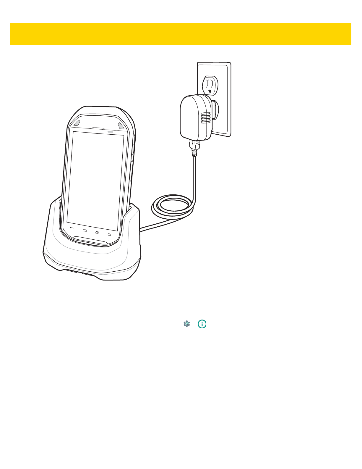
Charging the Battery
CAUTION Ensure that you follow the guidelines for battery safety described in Battery Safety Guidelines on page
8-1.
Before using the MC40 for the first time, charge the main battery until the Right light emitting diode (LED) turns
solid green (see Ta ble 1 -1 o n pag e 1- 3 for charge status indications). To charge the MC40, use a cable or a cradle
with the appropriate power supply. For information about the accessories available for the MC40, see Chapter 2,
Accessories.
The MC40 is equipped with a memory backup battery that automatically charges from the fully-charged main
battery . When using the MC40 for the first time, the backup battery requires approximately 36 hours to fully charge.
This is also true any time the backup battery is discharged, which occurs when the main battery is removed for
several hours. The backup battery retains random access memory (RAM) data in memory for at least 10 minutes
(at room temperature) when the MC40’s main battery is removed, when Battery Swap feature is used. When the
MC40 reaches a very low battery state, the combination of main battery and backup battery retains RAM data in
memory for at least 48 hours.
For cable and cradle setup and charging procedures see Chapter 2, Accessories.
• Micro USB Cable
• Single Slot Charging Cradle
• Five Slot Charge Only Cradle.
Page 19

Table 1-1 Battery Charge LED Status
Status Indications
Off MC40 is not charging.
MC40 is not inserted correctly in the cradle.
MC40 is not connected to a power source.
Charger or cradle is not powered.
Getting Started 1 - 3
Slow Blinking Amber (3 blinks
every 2 seconds)
Solid Green Charging complete.
Fast Blinking Amber (3
blinks/second)
Flashes Amber once (when Power
button pressed)
Fast Blinking Amber (when Power
button pressed)
MC40 is charging.
The battery is below 20%.
Charging error, e.g.:
Temperature is too low or too high.
Charging has gone on too long without completion (typically eight hours).
Critical battery state. Battery too low to boot device.
Battery over-temperature condition. Device shuts down. Battery will not
charge until temperature returns to normal operating value.
Charging Temperature
Charge batteries in ambient temperatures from 0 °C to 40 °C (32 °F to 104 °F) or up to 45 °C (113 °F) as reported
by the battery. To view the battery temperature, touch > About device > Battery Information.
Note that charging is intelligently controlled by the MC40. To accomplish this, for small periods of time, the MC40 or
accessory alternately enables and disables battery charging to keep the battery at acceptable temper atures. The
MC40 or accessory indicates when charging is disabled due to abnormal temperatures via its LED.
Charging Spare Batteries
See Chapter 2, Accessories for information on using accessories to charge spare batteries.
Powering On the MC40
If the MC40 did not turn on when the battery was installed, press the Power button until the Right and Left LEDs
flash once. The splash screen displays for about a minute as the MC40 initializes its flash file system. Note that
these windows also appear upon reset.
NOTE The MC40 Android Lollipop version contains a known limitation that for every first reboot (after flashing or
an enterprise/factory reset), the device may take approximately eight minutes to boot to the home screen.
Replacing the Battery
NOTE Ensure that the Battery Swap mode procedures are followed, otherwise the backup battery will deplete
quickly.
Page 20
1 - 4 MC40 Mobile Computer Integrator Guide for AOSP Version 5.1.1
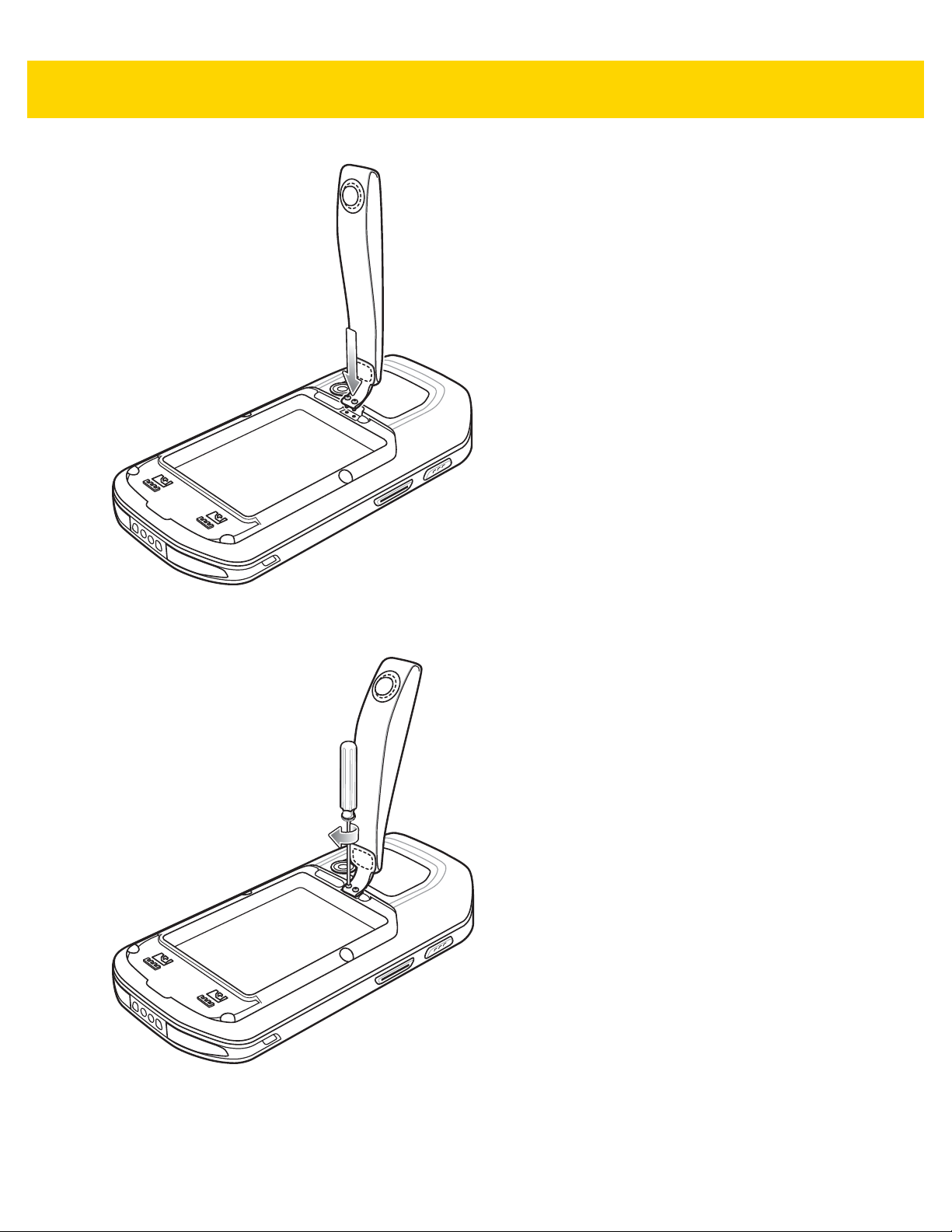
1. Press the Power button until the menu displays.
2. Touch Battery swap. The Right and Left LEDs light red.
3. Wait until the LEDs turns off.
4. Lift the battery latch.
Figure 1-2 Lift Battery Latch
5. Remove the battery out of the battery compartment.
Figure 1-3 Remove Battery
6. Align the replacement battery in the battery compartment.
7. Lower the battery and press down until it snaps into place.
8. Press down on the battery latch.
9. Press the Power button to turn on the MC40.
Page 21

Resetting the Device
There are four reset functions:
• Soft Reset
• Hard Reset
• Enterprise Reset
• Factory Reset.
Performing a Soft Reset
Perform a soft reset if applications stop responding.
1. Press and hold the Power button until the menu appears.
2. Touch Reboot.
3. The device shuts down and then reboots.
Performing a Hard Reset
Getting Started 1 - 5
Perform a Hard Reset if the device stops responding. To perform a Hard Reset:
1. Simultaneously press the Power, Left Scan/Action and Up Volume buttons.
2. The device shuts down and then reboots.
Performing an Enterprise Reset
An Enterprise Reset erases all data in the /cache and /data partitions and clears all device settings, except
those in the /enterprise partition.
Before performing an Enterprise Reset, copy all applications and the key remap configuration file that you want to
persist after the reset into the /enterprise/usr/persist folder.
1. Download the Enterprise Reset file from the Zebra Support & Downloads web site.
2. Copy the Enterprise Reset zip file (M40N0LXXXRE0000002.zip) to the root dire ctory of the On Device Storage.
See Chapter 3, USB Communication.
3. Press and hold the Power button until the menu appears.
4. Touch Reboot. The device shuts down and then reboots.
5. Press and hold the Left Scan/Action button.
6. When the System Recovery screen appears release the button.
Page 22

1 - 6 MC40 Mobile Computer Integrator Guide for AOSP Version 5.1.1
T
Figure 1-4 System Recovery Screen
7. Press the Up and Down Volume buttons to navigate to the Apply update from On Device Storage option.
8. Press the PTT button.
9. Press the Up and Down Volume buttons to navigate to the Enterprise Reset zip file
(M40N0LXXXRE0000002.zip).
10. Press the PTT button. The Enterprise Reset occurs and then the device resets.
11. Press the Volume Up and Volume Down buttons to navigate to the Reboot system now option.
12. Press the PTT button to reboot the device.
Performing a Factory Reset
A Factor y Re se t er ases all da ta in the /cache, /data and /enterprise partitions in internal storage and clears
all device settings. A Factory Reset returns the device to the last installed operating system image. To revert to a
previous operating system version, re-install that operating system image. See System Update on page 7-6 for
more information.
1. Download the Factory Reset file from the Zebra Support & Downloads web site.
2. Copy the Factory Reset zip file (M40N0LXXXRF0000002.zip) to the root directory of the On Device Storage.
See Chapter 3, USB Communication.
3. Press and hold the Power button until the menu appears.
4. Touch Reboot. The device shuts down and then reboots.
5. Press and hold the Left Scan/Action button.
6. When the System Recovery screen appears release the button.
Page 23

Getting Started 1 - 7
Figure 1-5 System Recovery Screen
7. Press the Up and Down volume buttons to navigate to the Apply update from On Device Storage option.
8. Press the PTT button.
9. Press the Up and Down volume buttons to navigate to the Factory Reset zip file (M40N0LXXXRF0000002.zip).
10. Press the PTT button. The Factory Reset occurs and then the device resets.
11. Press the Volume Up and Volume Down buttons to navigate to the Reboot system now option.
12. Press the PTT button to reboot the device.
Page 24

1 - 8 MC40 Mobile Computer Integrator Guide for AOSP Version 5.1.1
Page 25

CHAPTER 2 ACCESSORIES
This chapter provides information for using the accessories for the device.
MC40 Accessories
MC40 Accessories lists the accessories available for the MC40.
Table 2-1 MC40 Accessories
Accessory Part Number Description
Cradles
Single Slot Charge
Only Cradle
Five Slot Charge Only
Cradle Base
Five Slot Charge Only
Cradle
Chargers
Four Slot Battery
Charger
Power Supply PWRS-124306-01R Provides power to the MC40 and Single Slot Charge
Power Supply (12
VDC, 4.16 A)
Cables
Micro USB Cable 25-MCXUSB-01R Provides power to the MC40 and USB
CRDMC40XX-1000R Charges the MC40.
CRDUNIV-XX-5000R Provides charging for up to five MC40 devices or four
MC40 devices and one Four Slot Battery Charger
using optional Charging Cups. Requires additional
power supplies.
CRDUNIV-40-5000R Provides charging for up to five MC40 devices.
SACMC40XX-4000R Charges up to four MC40 batteries.
Cradle.
PWRS-14000-148C Provides po we r to th e Fiv e Slot Char g e Only Cra dle
and the Four Slot Battery Charger.
communication with a host computer.
Page 26

2 - 2 MC40 Mobile Computer Integrator Guide for AOSP Version 5.1.1
Table 2-1 MC40 Accessories (Continued)
Accessory Part Number Description
US AC Line Cord
(3-wire)
2-way DC Cable 25-122026-02R Connects one power supply (PWRS-14000-148C) to
4-way DC Cable 25-85992-01R Connects one power supply (PWRS-14000-241R) to
Miscellaneous
Spare 2680 mAh
lithium-ion battery
Charging Cup CUPMC40XX-1000R Mounts onto the Five Slot Charge Only Cradle Base
Battery Charger Cup CUPUNIBTRY-1000R Mounts on the Five Slot Charge Only Cradle Base
Universal Blank Slot
Cover
Protective Rubber
Boot
23844-00-00R Provides power to the power supplies.
two Four Slot Battery Chargers.
four Four Slot Battery Chargers.
BTRY-MC40EAB0E
BTRY-MC40EAB0E-10R
CUPUNICVR-5000R Mounts on the Five Slot Charge Only Cradle and
SG-MC40-RBOOT-01R
SG-MC40-RBOOT-10R
Replacement 2680 mAh battery.
Replacement 2680 mAh battery (10-pack)
and provides MC40 charging slot (Single pack).
and provides mounting for the Four Slot Battery
Charger.
covers a slot when a cup is not required (5-pack).
Provides additional protection for the MC40.
Provides additional protection for the MC40 (10–
pack).
Soft Hip Holster SG-MC40HLSTR-02R Mounts on belt and provides storage for the MC40.
Finger Strap SG-MC40STRAP-01R
SG-MC40STRAP-10R
Rack/Wall Mount
Bracket
Wired Headset HDST-25MM-PTVP-01 2.5 mm wired headset for PTT and VoIP telephony
KT-UNIVLBRKT-01R Provides for mounting the Five Slot Charge Only
Mounts on the back of the MC40 and provides se cure
option for holding the device (Single pack or
10-pack).
Cradle onto a standard rack or wall.
communications.
Page 27

Single Slot Charge Only Cradle
USB Port USB Port USB Cable
USB Cable Cable Channel Cable Channel
The Single Slot Charge Only Cradle provides power for operating and charging the MC40.
NOTE Do not connect the micro USB cable from the Single Slot Charge cradle to a host computer USB port. The
cradle cannot charge the MC40 if connected to a host computer.
Single Slot Charge Cradle Setup
1. Plug the micro USB connector into the microUSB port on the cradle.
2. Route the micro USB end of the Micro USB Cable through the Cable Channel and exit either to the front or
back of the cradle.
Accessories 2 - 3
Figure 2-1 Micro USB Cable Installation
3. Plug the other end of the Micro USB Cable into the USB port on the power supply.
4. Plug the power supply into a wall outlet.
Page 28
2 - 4 MC40 Mobile Computer Integrator Guide for AOSP Version 5.1.1
Micro USB Cable
Power Supply
Figure 2-2 Single Slot Charge Only Cradle Setup
Removing Cradle Insert
1. With finger nail, grasp insert notch.
Figure 2-3 Grasp Insert Notch
2. Pull insert out of cradle.
Page 29

Accessories 2 - 5
Figure 2-4 Remove Insert
Charging Using the Single Slot Charge Only Cradle
To charge the MC40 battery, place the MC40 into the cradle.
Page 30
2 - 6 MC40 Mobile Computer Integrator Guide for AOSP Version 5.1.1
Figure 2-5 MC40 Battery Charging
The Right LED indicates the status of the battery charging. See Table 1-1 on page 1-3 for charging status
indications. The 2680 mAh battery charges in approximately four hours.
Charge batteries in ambient temperatures from 0 °C to 40 °C (32 °F to 104 °F) or up to 45 °C (113 °F) as reported
by the battery. To view the battery temperature, touch > About device > Battery Information. Charging is
intelligently controlled by the MC40. To accomplish this, for small periods of time, the charger alternately enables
and disables battery charging to keep the battery at acceptable temperatures. The charger indicates when
charging is disabled due to abnormal temperatures via its LED.
Page 31

Four Slot Battery Charger
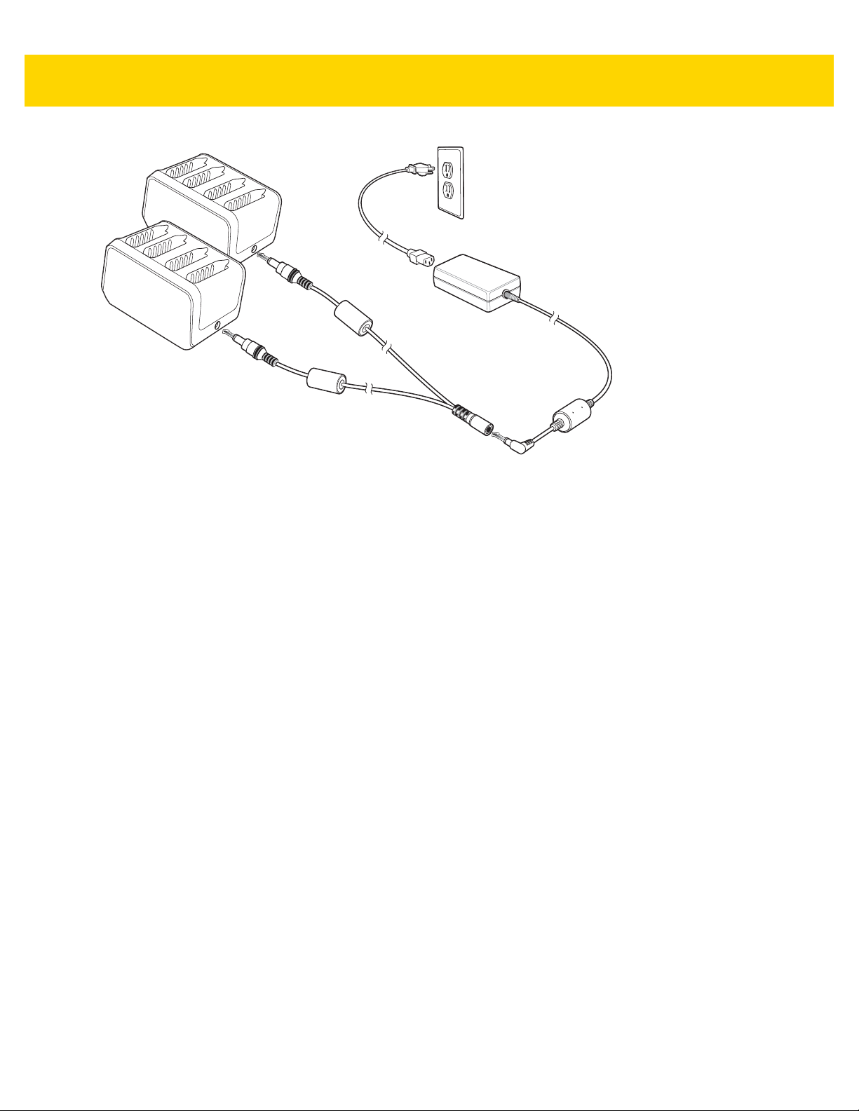
The Four Slot Battery Charger charges up to four MC40 spare batteries.
Single Charger Setup
1. Plug the power supply plug into the power port on the back of the charger.
2. Plug the AC line cord into the power supply.
3. Plug the AC line cord into an AC outlet.
Accessories 2 - 7
Figure 2-6 Four Slot Battery Charger
Two Charger Setup
1. Plug the 2-way DC Cable plugs into the power port on the back of the each charger.
2. Plug the power supply plug into the jack of the 2-way DC Cable.
3. Plug the AC line cord into the power supply.
4. Plug the AC line cord into an AC outlet.
Page 32
2 - 8 MC40 Mobile Computer Integrator Guide for AOSP Version 5.1.1
Figure 2-7 Setup with 2–way DC Cable
Four Charger Setup
1. Plug the 4-way DC Cable plugs into the power port on the back of the each charger.
2. Plug the 4-way DC Cable connector into the power output of the power supply.
3. Plug the AC line cord into the power supply.
4. Plug the AC line cord into an AC outlet.
Page 33

Accessories 2 - 9
Figure 2-8 Setup with 4–way DC Cable
Charging with the Four Slot Battery Charger
To charge the spare batteries insert the spare battery into a spare battery charging well.
A Charge LED is provided for each battery charging well. See Table 2-2 on page 2-10 for charging status
indications. The 2680 mAh battery charges in approximately four hours.
Page 34

2 - 10 MC40 Mobile Computer Integrator Guide for AOSP Version 5.1.1
Figure 2-9 Charging Batteries
Charge batteries in temperatures from 0 °C to 40 °C (32 °F to 104 °F). Charging is intelligently controlled by the
charger in order to ensure safe operation and op tim i ze long- ter m bat ter y life. To accomplish this, for small per iod s
of time, the charger alternately enables and disables battery charging to keep the battery at acceptable
temperatures. The charger indicates when charging is disable d due to abnormal te mperature s via the Charge LED.
Table 2-2 Spare Battery Charge LED Status
Status Indications
Off No battery a slot.
Battery is not charging.
Battery is not inserted correctly in the charger.
Charger is not powered.
Slow Blinking Amber Battery is charging.
Solid Green Charging complete.
Fast Blinking Amber Charging error, e.g.:
• Temperature is too low or too high.
• Charging has gone on too long without completion.
Page 35
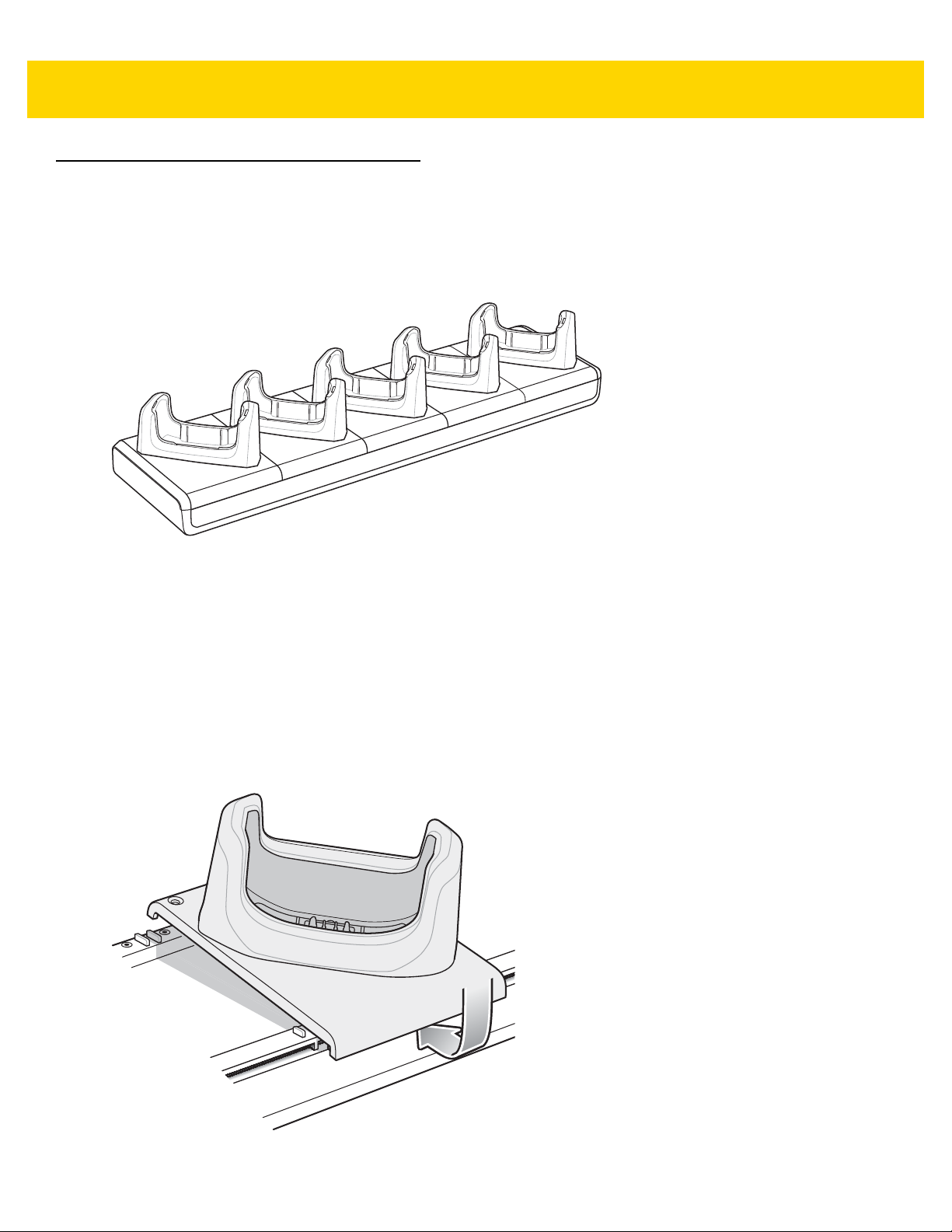
Five Slot Charge Only Cradle
The Five Slot Charge Only cradle:
• Provides power for operating and charging the MC40.
• Simultaneously charges up to five MC40s.
Accessories 2 - 11
Figure 2-10 Five Slot Charge Only Cradle
Installing a Cup
The Five Slot Charge Only Cradle ships without any cradle cups installed. To base accepts the MC40 Charging
Cup, Battery Charger Cup and Blank Slot Cover. To install the cradle cups:
1. Remove power from the cradle base before installing cups.
2. Align the lip of the cup with the slot on the front of the cradle. Ensure that the cup is positioned within the Slot
Alignment Tabs.
Figure 2-11 Five Slot Charge Only Cradle Cup Installation
Page 36

2 - 12 MC40 Mobile Computer Integrator Guide for AOSP Version 5.1.1
3. Slide the lip into the slot and rotate the cup until it is flat on the cradle base.
4. Using a Phillips screwdriver, secure the cup to the charger base using the two screws provided with the cup.
Figure 2-12 Securing Cup to Base
5. Each slot on the Cradle Base must have a cup installed.
6. Repeat for each additional cup.
Installing a Four Slot Battery Charger
To install a Four Slot Battery Charger:
1. Install a Battery Charger Cup. See Installing a Cup on page 2-11.
2. Align the mounting slots on the bottom of the Four Slot Battery Charger with the screws on the cup.
3. Slide the Four Slot Battery Charger down until it snaps into place.
Page 37

Accessories 2 - 13
Figure 2-13 Multi Slot Charge Only Cradle Four Slot Battery Charger Installation
Power to Five Slot Charge Only Cradle
Use one power supply to provide power to the Charging Base to power the Charging Cups. A separate power
supply is required for each Four Slot Battery Charger installed. The power supply is connected directly to the Four
Slot Battery Charger.
Page 38

2 - 14 MC40 Mobile Computer Integrator Guide for AOSP Version 5.1.1
Figure 2-14 Five Slot Charge Only Cradle Power Connections
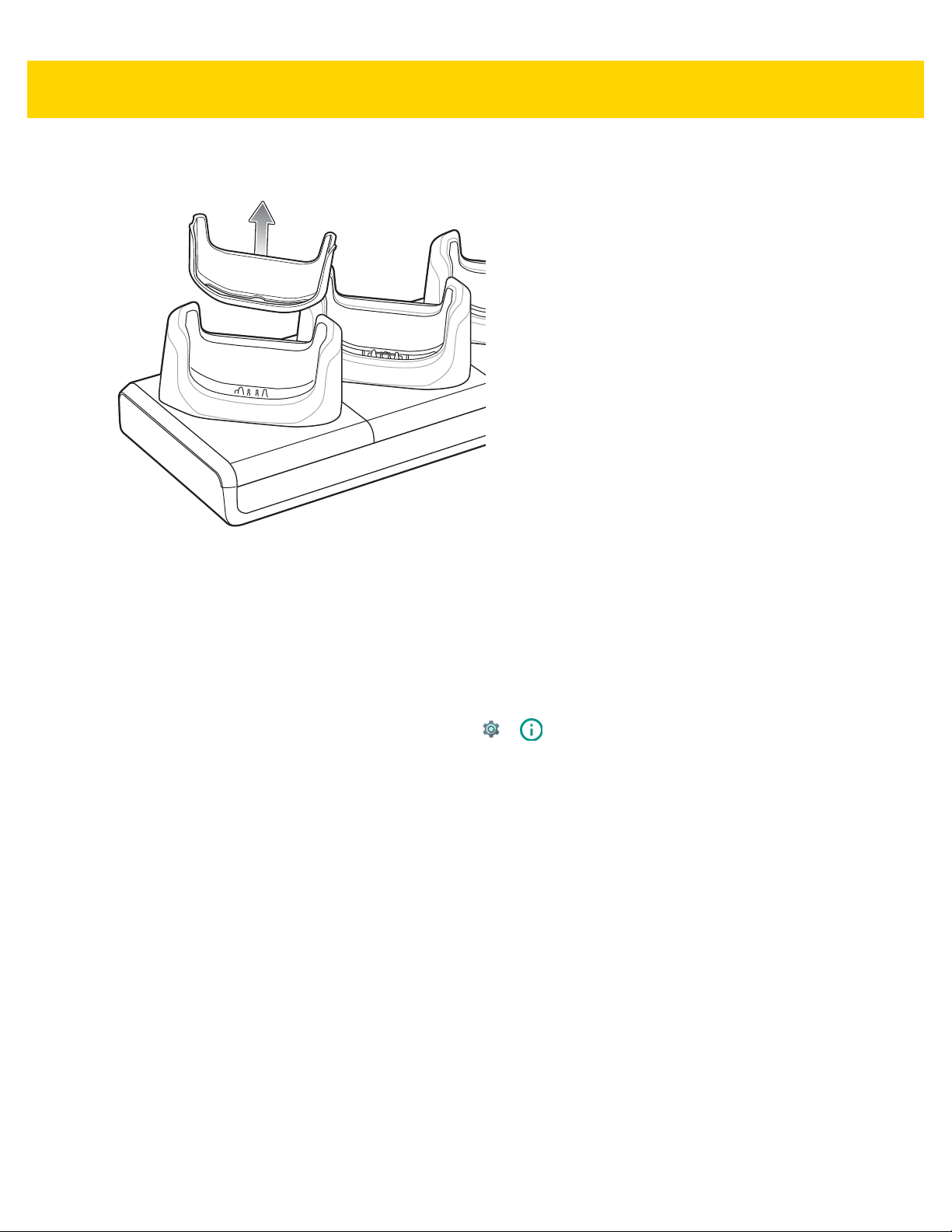
Removing Cradle Insert
1. With finger nail, grasp insert notch.
Figure 2-15 Grasp Insert Notch
2. Pull insert out of cradle.
Page 39
Accessories 2 - 15
Figure 2-16 Remove Insert
Charing Using the Five Slot Charge Only Cradle
Insert the MC40 into a slot to begin charging.
The Right LED indicates the status of the battery charging in the MC40. See Table 1-1 on page 1-3 for charging
status indications. The 2680 mAh battery charges in approximately four hours.
Charge batteries in ambient temperatures from 0 °C to 40 °C (32 °F to 104 °F) or up to 45 °C (113 °F) as reported
by the battery. To view the battery temperature, touch > About device > Battery Information. Charging is
intelligently controlled by the MC40. To accomplish this, for small periods of time, the charger alternately enables
and disables battery charging to keep the battery at acceptable temperatures. The charger indicates when
charging is disabled due to abnormal temperatures via its LED.
Page 40

2 - 16 MC40 Mobile Computer Integrator Guide for AOSP Version 5.1.1
Figure 2-17 Charging MC40 and Spare Battery
Installing the Finger Strap
Use the optional finger strap to securely hold the MC40 while working.
1. Press the Power button until the Device options menu appears.
2. Touch Power off.
3. Remove the battery.
Page 41
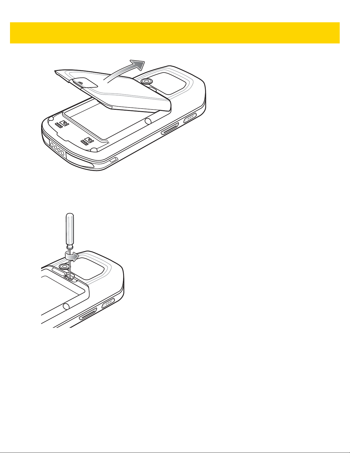
Figure 2-18 Remove Battery
4. Using a Phillips screwdriver, remove the two screws securing the plug to the MC40.
Accessories 2 - 17
Figure 2-19 Remove Plug
5. Align the screws in the bracket of the finger strap with the mounting holes on the MC40.
Page 42
2 - 18 MC40 Mobile Computer Integrator Guide for AOSP Version 5.1.1
Figure 2-20 Align Finger Strap
6. Secure the finger strap to the MC40 using a Phillips screwdriver.
Figure 2-21 Secure Finger Strap to MC40
7. Replace the battery.
Page 43

Accessories 2 - 19
Figure 2-22 Install Battery
Installing the Rubber Boot
Use the rubber boot to add additional protection to the MC40.
Figure 2-23 Rubber Boot
1. Insert the bottom of the MC40 into the bottom of the rubber boot.
Page 44

2 - 20 MC40 Mobile Computer Integrator Guide for AOSP Version 5.1.1
Figure 2-24 Insert MC40 into Boot
2. Pull the top of the rubber boot over the top of the MC40.
Figure 2-25 Pull Boot Over MC40
3. Ensure that the rubber boot is sitting flat against the MC40.
Page 45
Ethernet Settings
The following settings can be configured when using Ethernet communication:
• Proxy Settings
• Static IP.
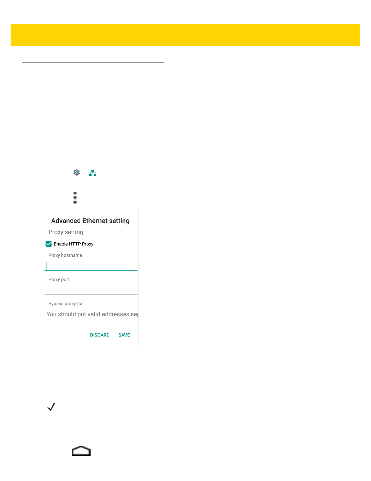
Configuring Ethernet Proxy Settings
The MC40 includes Ethernet cradle drivers. The MC40 can conn ect to an Ethernet network using a third-party
Ethernet dongle. After connecting the MC40, configure the Ethernet connection:
1. Place the MC40 into the Ethernet cradle slot.
2. Touch > Ethernet.
3. Slide the switch to the ON position.
4. Touch > Advanced.
Accessories 2 - 21
Figure 2-26 Ethernet Proxy Settings
5. Touch Enable HTTP Proxy.
6. In the Proxy hostname field, enter the proxy server address.
7. In the Proxy port field, enter the proxy server port number.
NOTE When entering proxy addresses in the Bypass proxy for field, do not use spaces or carriage returns
between addresses.
8. In the Bypass proxy for text box, enter addresses for web sites that do not require to go through the proxy
server. Use the separator “|” between addresses.
9. Touch Save.
10. Touch .
Page 46
2 - 22 MC40 Mobile Computer Integrator Guide for AOSP Version 5.1.1
Configuring Ethernet Static IP Address
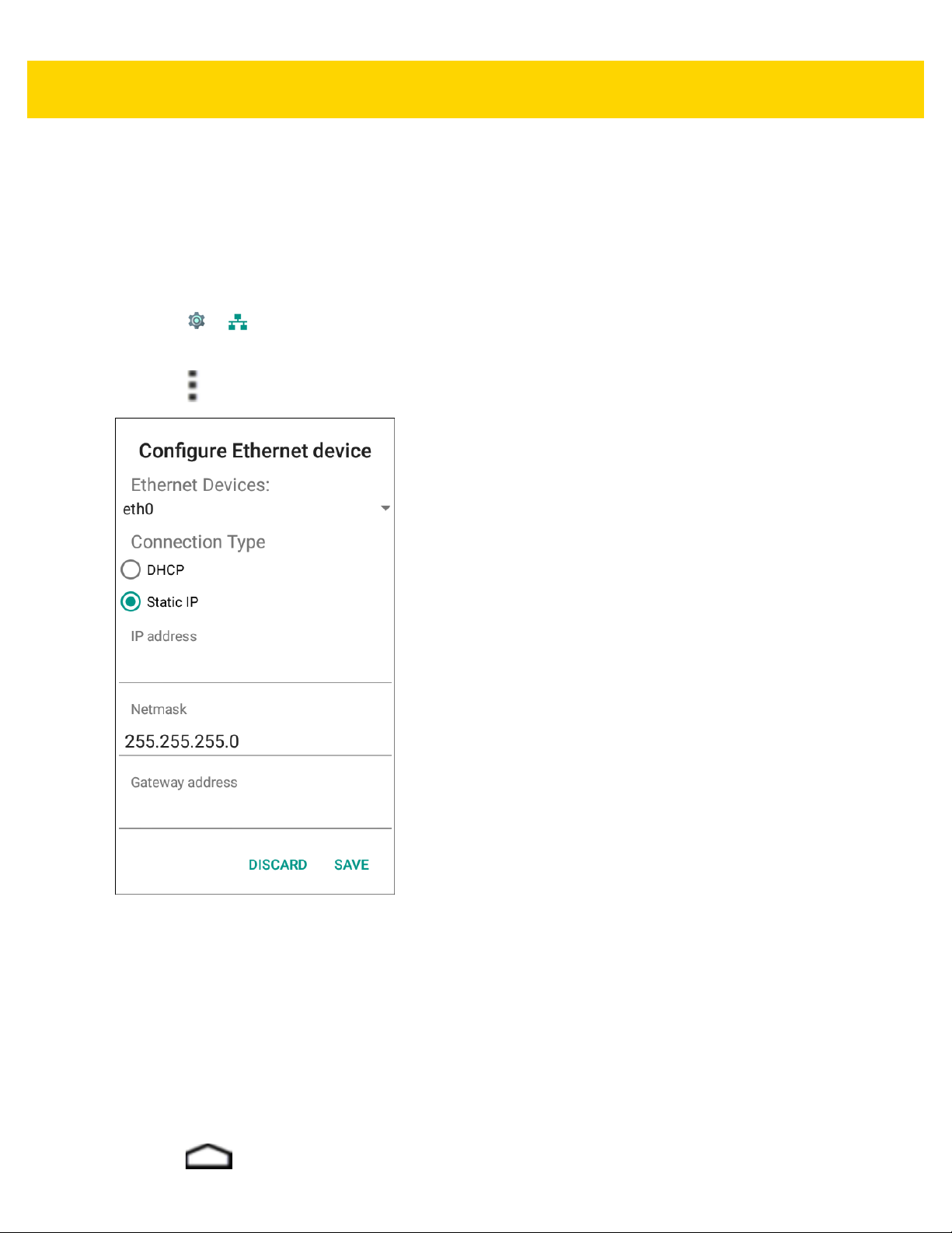
The MC40 includes Ethernet cradle drivers. The MC40 can conn ect to an Ethernet network using a third-party
Ethernet dongle. After connecting the MC40, configure the Ethernet connection. By default, the device is
configured to use Dynamic Host Configuration Protocol (DHCP) to assign an Internet Protocol (IP) address when
connecting to an Ethernet network. To configure the device to connect to a network using a static IP address:
1. Place the MC40 into the Ethernet cradle slot.
2. Touch > Ethernet.
3. Slide the switch to the ON position.
4. Touch > Config.
Figure 2-27 Configure Ethernet Device Settings
5. Under Connection Type, touch the Static IP radio button.
DHCP is the default Connection Type.
6. In the IP address field, enter the proxy server address.
7. If required, in the Netmask text box, enter the network mask address.
8. If required, in the Gateway address text bo x, en te r a ga te wa y addr es s for the de vic e.
9. If required, in the DNS 1 address text box, enter a Domain Name System (DNS) address.
10. If required, in the DNS 2 address text box, enter a DNS address.
11. Touch Save.
12. Touch .
Page 47

CHAPTER 3 USB COMMUNICATION
This chapter provides information for transferring files between the device and a host computer.
Connecting to a Host Computer via USB
Connect the device to a host computer using the micro USB cabl e to tran sfer files between the MC40 and the host
computer. ADB connectivity on Android Lollipop requires the latest ADB driver (1.0.32 or later) to be installed on
the computer.
CAUTION When connecting the MC40 to a host computer , follow the host computer’s instructions for connecting
and disconnecting USB devices, to avoid damaging or corrupting files.
1. Connect the micro USB connector to the USB port on the device. See Chapter 2, Accessories for setup
information.
2. Connect the USB A connector to the host computer USB port.
Connected as a media device or Connected as camera appears on the Status bar.
3. If Connected as a camera appears, pull down the Notification shade and touch Connected as a camera and
then touch Media device (MTP).
CAUTION Ensure that all applications are not running. Loss of data may occur.
4. On the host computer, open a file explorer application.
NOTE While USB storage is in use, access to the On Device Storage is disabled.
5. Locate the device as a portable device and open to view contents.
6. Copy or delete files as required.
Page 48

3 - 2 MC40 Mobile Computer Integrator Guide for AOSP Version 5.1.1
Disconnect from the Host Computer
CAUTION Carefully follow the host computer’s instructions to unmount the microSD card and disconnect USB
devices correctly to avoid losing information.
1. On the host computer, unmount the device.
2. Remove the micro USB cable from the device.
Page 49

CHAPTER 4 DATAWEDGE
CONFIGURATION
DataWedge Configuration
This chapter applies to DataWedge on Android devices. DataWedge is an application that reads data, processes
the data and sends the data to an application.
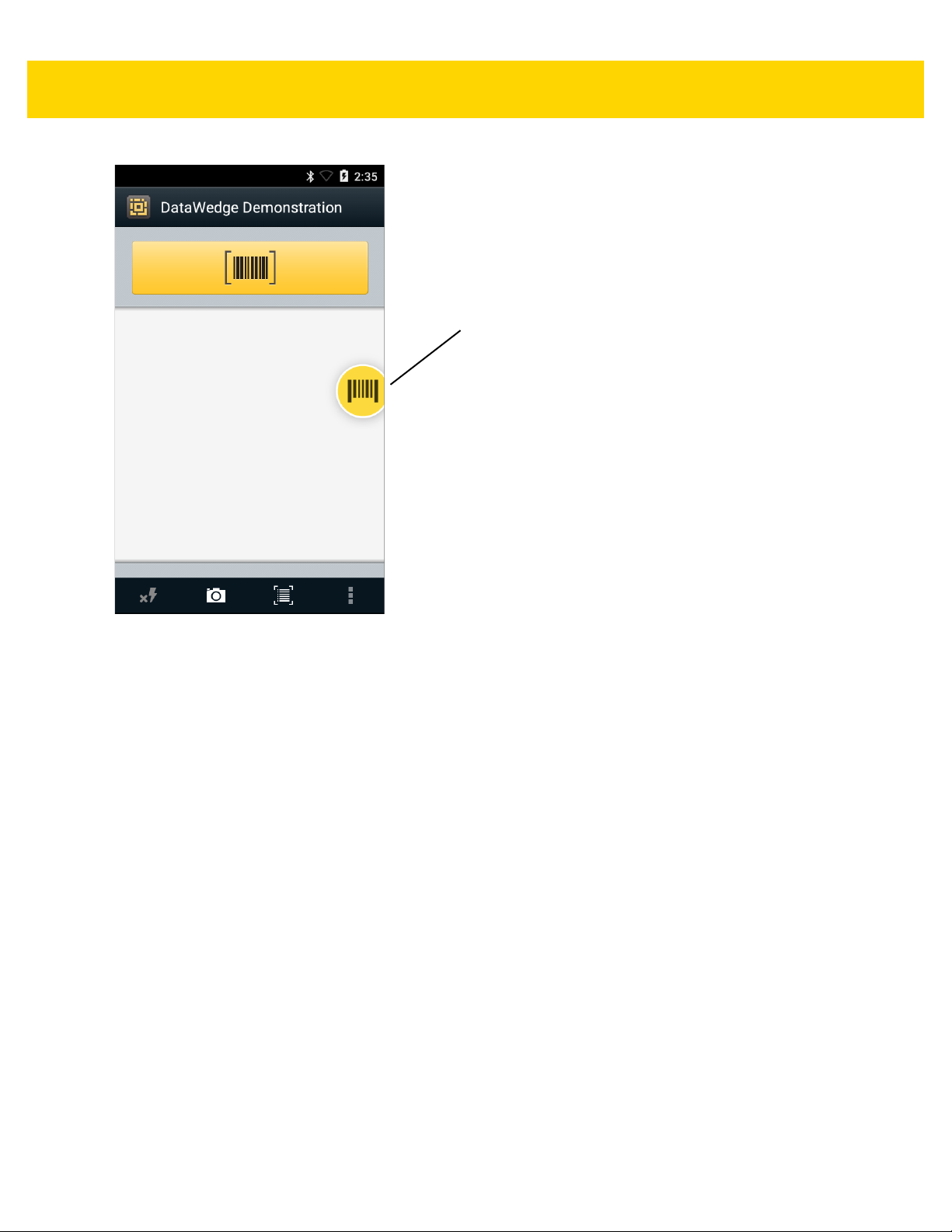
Basic Scanning
Scanning can be performed using either the imager or the rear-facing camera.
Using the Imager
To capture bar code data:
1. Ensure that an application is open on the MC40 and a text field is in focus (text cursor in text field).
2. Aim the exit window at a bar code.
3. Press and hold the Right Scan/Action button. The r ed lase r aim ing p attern turns on to assist in a iming . En sure
that the bar code is within the area formed by the aiming pattern. The Left and Right LEDs light red to indicate
that data capture is in process.
Figure 4-1 Data Capture
4. The Left and Right LEDs light green, a beep sounds and the MC40 vibrates, by default, to indicate the bar code
was decoded successfully. The captured data appears in the text field.
Page 50

4 - 2 MC40 Mobile Computer Integrator Guide for AOSP Version 5.1.1
Using the Camera
To capture bar code data:
1. Ensure that an application is open on the MC40 and a text field is in focus (text cursor in text field).
2. Aim the rear-facing camera at a bar code.
3. Press and hold the Right Scan/Action button. By default, a preview window appears on the screen. The Left
and Right LEDs light red to indicate that data capture is in process.
Figure 4-2 Data Capture with Camera
4. Move the MC40 until the bar code is centered under the red target.
5. The Left and Right LEDs light green, a beep sounds and the MC40 vibrates, by default, to indicate the bar code
Profiles
DataWedge is based on profiles and plug-ins. A profile contains information on how DataWedge should behave
with different applications.
Profile information consists of:
• Associated application
• Input plug-in configurations
• Output plug-in configurations
• Process plug-in configurations.
was decoded successfully. The captured data appears in the text field.
Page 51

DataWedge Communication 4 - 3
Using profiles, each application can have a specific DataWedge configuration. Fo r ex amp le, ea ch user ap plication
can have a profile which outputs scanned data in the required format when that application comes to the
foreground. DataWedge can be configured to process the same set of captured data differently based on the
requirements of each application.
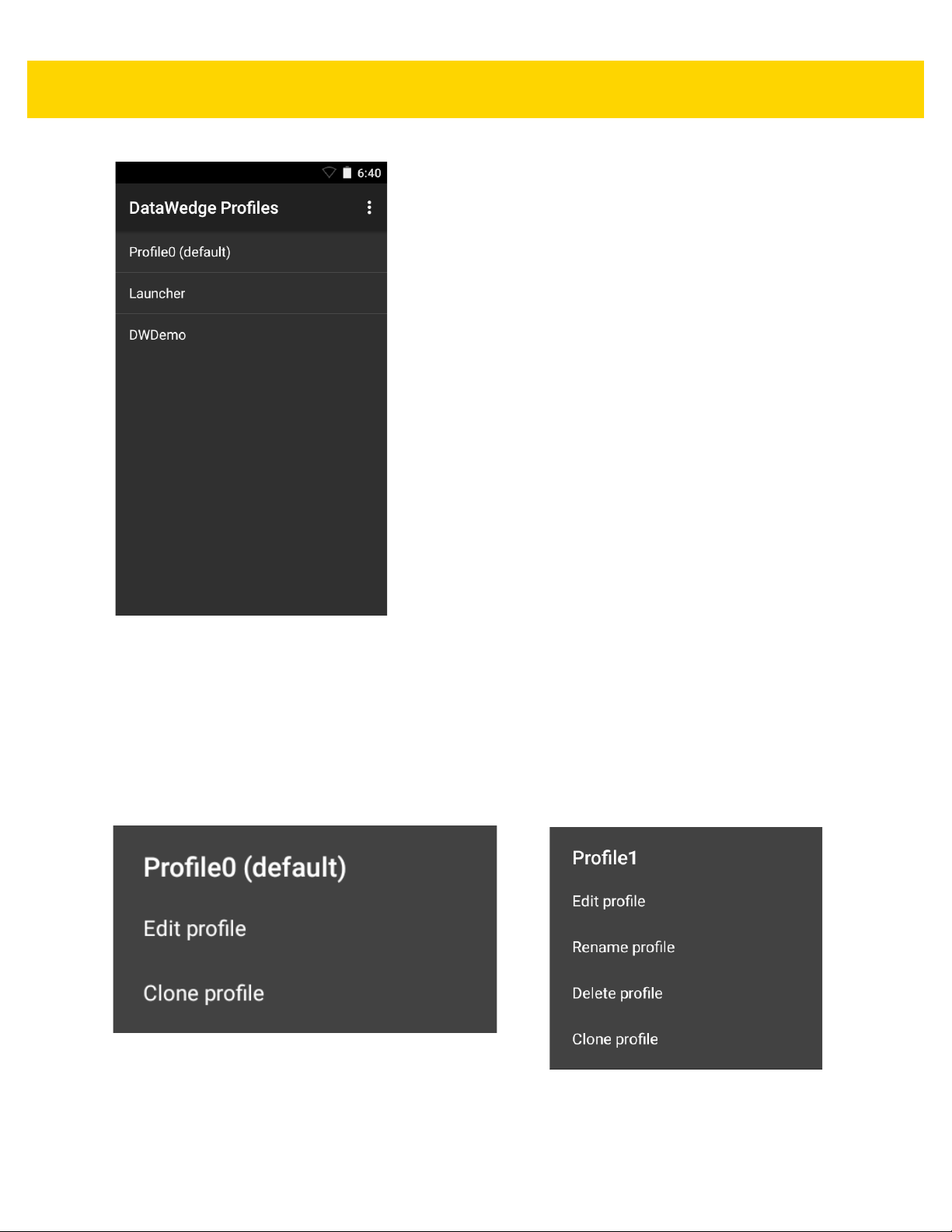
DataWedge includes the following visible and hidden pre-configured profiles which support specific built-in
applications:
• Visible profiles:
•Profile0 - created automatically the first time DataWedge runs. Generic profile used when there are no
user created profiles associated with an application.
• Launcher - disables scanning when the Launcher is in foreground . Note: to save battery power, disable
this profile when not required.
•DWDemo - provides support for the DWDemo application.
• DataWedge has built-in configurations for RD Client, MSP Agent, MspUserAttributes, and RhoElements.
• DataWedge disables scanning when the default camera application is i the foreground.
Profile0
Profile0 can be edited but cannot be associated with an application. That is, DataWedge allows manipulation of
plug-in settings for Profile0 but it does not allow assignment of a foreground application. This configuration allows
DataWedge to send output data to any foreground application ot her than applications associated with user-defined
profiles when Profile0 is enabled.
Profile0 can be disabled to allow DataWedge to only send output data to those applications which are associated
in user-defined profiles. For example, create a profile associating a specific application, disable Profile0 and then
scan. DataWedge only sends data to the application specified in the user-created profile. This adds additional
security to DataWedge enabling the sending of data only to specified applications.
Plug-ins
A plug-in is a software module utilized in DataWedge to extend its functionality to encompass technologies such as
bar code scanning. The plug-ins can be categorized into three types based on their operations:
• Input Plug-ins
• Output Plug-ins
• Process Plug-ins.
Input Plug-ins
An Input Plug-in supports an input device, such as a bar code scanner contained in, or attached to the device.
DataWedge contains base plug-ins for these input devices.
• Bar Code Scanner Input Plug-in – The Bar Code Scanner Inpu t Plug-in is responsible for reading data from
the integrated bar code scanner and supports diff erent types of bar code reade rs including laser, imager and
internal camera. Raw data read from the bar code scanner can be processed or formatted using Process
Plug-ins as required. DataWedge has built-in feedback functionality for the bar code scanner to issue user
alerts. The feedback settings can be configured according to user requirement.
• MSR Input Plug-in – The Magnetic Stripe Reader (MSR) Input Plug-in is responsible for reading data from
an MSR. Raw data read from the MSR can be processed or formatted using Process Plug-ins as required.
Page 52

4 - 4 MC40 Mobile Computer Integrator Guide for AOSP Version 5.1.1
DataWedge has built-in feedback functionality for the MSR to issue user alerts. The feedback settings can
be configured according to user requirement.
Output Plug-ins
Output Plug-ins are responsible for sending the data from Input Plug-ins to a foreground application on the device.
• Keystroke Output Plug-in – The Keystroke Output Plug-in collects and sends data received from the Input
Plug-in to the foreground applications by emulating keystrokes.
• Intent Output Plug-in – The Intent Ou tput Plug-in collects and sends data received from the Input Plug-ins
to foreground applications using the Android Intent mechanism.
• IP Output Plug-in – The IP Output Plug-in collects and sends d ata received from the Inp ut Plug-ins to a host
computer via a network connection. Captured data can be sent over an IP network to a specified IP address
and port using either TCP or UDP transport protocols.
Process Plug-ins
Process Plug-ins are used in DataWedge to manipulate the received data according to the requirement, befo r e
sending to the foreground application via the Output Plug-in.
• Basic Data Formatting Process Plug-in– The Basic Data Formatting Plug-in allows DataWedge to add a
prefix and/or a suffix to the captured data before passing it to an Output Plug-in.
• Advanced Data Formatting Process Plug-in– The Advanced Data Formatting Plug-in allows DataWedge
to apply rules (actions to be performed based on defined criteria) to the data received via an input plug-in
before passing it to an Output Plug-in.
Profiles Screen
To launch DataWedge, touch > DataWedge. By default, three profiles appear:
•Profile0
• Launcher
•DWDemo.
Profile0 is the default profile and is used when no other profile can be applied.
Page 53
DataWedge Communication 4 - 5
Figure 4-3 DataWedge Profiles Screen
Profile names are color coded. Enabled profiles are white and disabled profiles are gray.
To configure a profile touch the profile name.
Profile Context Menu
Touch and hold a profile to open a context menu that allows additional actions to be performed on the selected
profile.
Figure 4-4 Profile Context Menu
The profile context menu allows the profile to be edited (same as just tapping on a profile), renamed, deleted or
cloned.
Page 54

4 - 6 MC40 Mobile Computer Integrator Guide for AOSP Version 5.1.1
Options Menu
Touch to open the options menu.
Figure 4-5 DataWedge Options Menu
The menu provides options to create a new profile, acce ss to general DataW edge settings and DataW edge version
information.
Disabling DataWedge
1. Touch > .
2. Touch > Settings.
3. Touch DataWedge enabled.
The blue check disappears from the checkbox indicating that DataWedge is disabled.
Creating a New Profile
To create a profile:
1. Touch > .
2. Touch > New profile.
3. In the New profile dialog box, enter a name for the new profile. It is recommended that profile names be
unique and made up of only alpha-numeric characters (A-Z, a-z, 0-9) .
Figure 4-6 New Profile Name Dialog Box
4. Touch OK.
The new profile name appears in the DataWedge profile screen.
Page 55

Profile Configuration
To configure the Profile0 or a user-crea ted profile, touch the profile name.
DataWedge Communication 4 - 7
Figure 4-7 Profile Configuration Screen
The configuration screen lists the following sections:
• Profile enabled
• Applications
• Data Capture Plus (DCP)
• Barcode input
• MSR input
• Keystroke output
• Intent output
• IP output.
Associating Applications
Use Applications option to associate applications with this profile. User created profiles should be associated with
one or more applications and its activities.
1. Touch Associated apps. A list of applications/activities associated with the profile displays. Initially the list
does not contain any applications/activities.
Page 56

4 - 8 MC40 Mobile Computer Integrator Guide for AOSP Version 5.1.1
Figure 4-8 Associated Apps Screen
2. Touch > New app/activity.
3. In the Select application screen, select the desired application from the list.
Page 57

DataWedge Communication 4 - 9
Figure 4-9 Select Application Menu
4. In the Select activity menu, selecting the activity adds that application/activity combination to the associated
application list for that profile. Selecting * as the activity results in all activities within that application being
associated to the profile. During opera tion , Da ta Wedge tries to match the specific application/activity
combinations with the foreground application/activity before trying to match the general application/*
combinations.
Page 58

4 - 10 MC40 Mobile Computer Integrator Guide for AOSP Version 5.1.1
Figure 4-10 Select Activity Menu
5. The selected applications/activites display for the profile.
Page 59

DataWedge Communication 4 - 11
Figure 4-11 Selected Application/Activity
6. Touch .
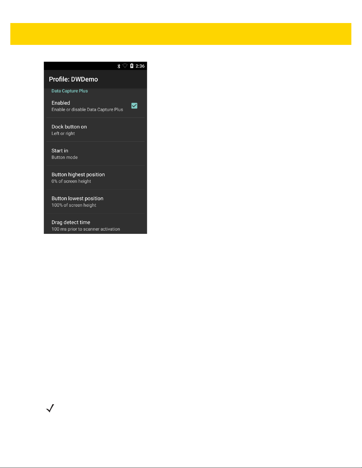
Data Capture Plus
The Data Capture Plus (DCP) is a DataWedge feature that enab les the user to initiate data capture by touching an
area on the screen. A button or screen overlay acts like a scan button.
Page 60
4 - 12 MC40 Mobile Computer Integrator Guide for AOSP Version 5.1.1
DCP Button
Figure 4-12 Data Capture Plus Dock Button
The DataWedge profile configuration screen allows the user to configure how the DCP appears on the screen once
the particular profile is enabled. The DCP is hidden by default. Enabling DCP option displays additional
configuration parameters.
Page 61
DataWedge Communication 4 - 13
Figure 4-13 Data Capture Plus Settings
• Enable - Select to enable Data Capture Plus (default - disabled).
• Dock button on - Select position of the button.
• Left or right - Allo ws user to place the button on either the right or left edge of the screen.
• Left only - Places the button on left edge of the screen.
• Right only - Places the button on the right edge of the screen.
•Start in - Select the initial DCP state.
• Fullscreen mode - DCP covers the whole screen.
• Button mode - DCP displays as a circular button on the screen and can be switched to fullscreen mode.
• Button only mode - DCP displays a s a circular button on the screen and cannot be switched to fu llscreen
mode.
• Button highest position - Select the top of the range the user is allowed to move the DCP, given as a
percent of the screen height (default - 0).
• Button lowest position - Select the bottom of the range the user is allowed to move the DCP, given as a
percent of the screen height (default - 100).
• Drag detect time - Select the time in milliseconds that the scanner waits before activating scanner. This
allows the user to drag the button without initiating scanner (default - 100 ms, maximum 1000 ms).
NOTE The DCP does not appear if the scanner is disabled in the profile even though the Enabled option is set.
In Button mode, the user can place DCP in full screen mode by dragging the button over Fullscreen mode. The
overlay covers the screen.
Page 62

4 - 14 MC40 Mobile Computer Integrator Guide for AOSP Version 5.1.1
Figure 4-14 Fullscreen Mode
Swipe down to return to button mode.
Bar Code Input
Use the Bar Code Input options to configure the Bar Code Scanner Input Plug-in for the profile.
Enabled
Enables or disables this plug-in. A check in the checkbox indicates that the plug-in is enabled.
Scanner Selection
Configures which scanning device to use for bar code data capture when the profile is active.
•Auto - The software automatically selects the 2D Barcode Imager.
• Camera Scanner - Scanning is performed with the rear-facing camera.
• 2D Barcode Imager - Scanning is performed using the 2D Imager.
• Bluetooth Scanner - Scanning is performed using an optional RS507 Hands-free Bluetooth scanner.
Decoders
Use the Bar Code Input options to configure the Bar Code Scanner Input Plug-in for the profile.
Configures which bar code decoders are en ab le d or disa ble d. For bes t perfo rm a nc e dis ab l e all un ne cessary
decoders.
Page 63

DataWedge Communication 4 - 15
Touch Decoders. The Barcode input screen appears. A check in the checkbox indicates that the decoder is
enabled. By default the most commonly used decoders are enabled. The supported decoders are:
NOTE DataWedge supports the decoders listed below but not all are validated on this device.
Touch to return to the prev iou s s cre e n.
Table 4-1 Supported Decoders
Symbology Bar Code Imager Camera RS507
Australian Postal Disabled Disabled Disabled
Aztec Enabled Enabled Enabled
Canadian Postal Disabled Disabled N/A
Chinese 2 of 5 Disabled Disabled Disabled
Codabar Enabled Enabled Enabled
Code 11 Disabled Disabled Disabled
Code 128 Enabled Enabled Enabled
Code 39 Enabled Enabled Enabled
Code 93 Disabled Disabled Disabled
Composite AB Disabled Disabled Disabled
Composite C Disabled Disabled D isabled
Discrete 2 of 5 Disabled Disabled Disabled
Datamatrix Enabled Enabled Enabled
Dutch Postal Disabled Disabled Disabled
EAN13 Enabled Enabled Enabled
EAN8 Enabled Enabled Enabled
GS1 DataBar Enabled Enabled Enabled
GS1 DataBar Expanded Enabled Enabled Enabled
GS1 DataBar Limited Disabled Disabled Disabled
HAN XIN Disabled Disabled N/A
Interleaved 2 of 5 Disabled D isabled Disabled
Japanese Postal Disabled Disabled Disabled
Korean 3of 5 Disabled Disabled Disabled
MAIL MARK Enabled Enabled N/A
Matrix 2 of 5 Disabled Disabled Disabled
Page 64

4 - 16 MC40 Mobile Computer Integrator Guide for AOSP Version 5.1.1
Table 4-1 Supported Decoders (Continue d )
Symbology Bar Code Imager Camera RS507
Maxicode Enabled Enabled Enabled
MicroPDF Disabled Disabled Disabled
MicroQR Disabled Disabled Disabled
MSI Disabled Disabled Disabled
PDF417 Enabled Enabled Enabled
QRCode Enabled Enabled Enabled
Decoder Signature Disabled Disabled Disabled
TLC39 Disabled D isabled Disabled
Trioptic 39 Disabled Disabled Disabled
UK Postal Disabled Disabled Disabled
UPCA Enabled Enabled Enabled
UPCE0 Enabled Enabled Enabled
UPCE1 Disabled Disabled Disabled
US4state Disabled Disabled Disabled
US4state FICS Disabled Disabled Disabled
US Planet Disabled Disabled Disabled
US Postnet Disabled Disabled Disabled
Decoder Params
Use Decode Params to configure individual decoder parameters.
Codabar
• CLSI Editing - Enable this parameter to strip the start and stop characters and insert a space after the first,
fifth, and tenth characters of a 14-character Codabar symbol. Enable this feature if the host system requires
this data format (default - disabled).
• Length1 - Use to set decode lengths (default - 6). See Decode Lengths on page 4-22 for more information.
• Length2 - Use to set decode lengths (default - 55). See Decode Lengths on page 4-22 for more information.
• NOTIS Editing - Enable this parameter to strip the start and stop characters from a decoded Codabar
symbol. Enable this feature if the host system requires this data format (default - disabled).
• Redundancy - Sets the reader to read the bar code twice before accepting data. A check in the checkbox
indicates that redundancy is enabled (default - enabled).
Code 11
• Length1 - Use to set decode lengths (default - 4). See Decode Lengths on page 4-22 for more information.
• Length2 - Use to set decode lengths (default - 55). See Decode Lengths on page 4-22 for more information.
Page 65

DataWedge Communication 4 - 17
• Redundancy - Sets the reader to read the bar code twice before accepting data. A check in the checkbox
indicates that redundancy is enabled (default - enabled).
• Report Check Digit - Transmit Code 11 data with or without the check digit. A check in the checkbox
indicates to send Code 11 data with check digit (default - disabled).
• Verify Check Digit - Check the integrity of all Code 11 symbols to verify that the data complies with the
specified check digit algorithm. This selects the check digit mechanism for the decoded Code 11 bar code.
• No Check Digit - Do not verify check digit.
• 1 Check Digit - Bar code contains one check digit (default).
• 2 Check Digits - Bar code contains two check digits.
Code128
• Code128 Reduced Quiet Zone - Enables decoding of margin-less Code 128 bar codes. (Available on Bar
Code Imager and Camera Scanner)
• Ignore Code128 FCN4 - When enabled, and a Code 128 bar code has an embedded FNC4 character , it will
be removed from the data and the following characters will not be changed. When the feature is disabled, the
FNC4 character will not be transmitted but the following character will have 128 added to it. (Available on Bar
Code Imager and Camera Scanner)
• Check ISBT Table - The ISBT specification includes a table that lists several types of ISBT bar codes that
are commonly used in pairs. If ISBT128 Concat Mode is set, enable Check ISBT Table to concatenate only
those pairs found in this table. Other types of ISBT codes are not concatenated. A check in the checkbox
indicates that redundancy is enabled (default - disabled).
• Enable GS1-128 - Set the GS1 128 subtype. A check in the checkbox indica tes that the option is enabled
(default - enabled).
• Enable ISBT128 - Set the ISBT128 subtype. A check in the checkbox indicates that the option is enabled
(default - enabled).
• ISBT128 Concatenation Mode - Select an option for concatenating pairs of ISBT code types:
• Concat Mode Never - Do not concatenate pairs of ISBT codes encountered (default).
• Concat Mode Always - There must be two ISBT codes in order to decode and perform concatenation.
Does not decode single ISBT symbols.
• Concat Mode Auto - Decodes and concatenates pairs of ISBT codes immediately. If only a single ISBT
symbol is present, the device must decode the symbol the number of times set via DataWedge
Configuration 4 - 11 Redundancy - Code128 before transmitting its data to confirm that there is no
additional ISBT symbol.
• Length1 - Use to set decode lengths (default - 0). See Decode Lengths on page 4-22 for more information.
• Length2- Use to set decode lengths (default - 55). See Decode Lengths on page 4-22 for more information.
• Redundancy - Sets the reader to read the bar code twice before accepting data. A check in the checkbox
indicates that redundancy is enabled (default - disabled).
• Security Level - The scanner of fers four levels of decode security for Cod e 128 bar codes. Select increasin g
levels of security for decreasing levels of bar code quality. There is an inverse relationship between security
and scanner aggressiveness, so choose only that level of security necessary for any given application.
• Security Level 0 - This setting allo ws the scan ner to ope ra te in its most aggressive state, while providing
sufficient security in decoding most “in-spec” bar codes.
• Security Level 1 - This setting eliminates most misdecodes (default).
• Security Level 2 - Select this option if Security level 1 fails to eliminate misdecodes.
• Security Level 3 - If Security Level 2 is selected and misdecodes still occur, select this security level. Be
advised, selecting this option is an extreme measure against mis-decoding severely out of spec bar
Page 66

4 - 18 MC40 Mobile Computer Integrator Guide for AOSP Version 5.1.1
codes. Selecting this level of security significantly impairs the decoding ability of the scanner. If this level
of security is needed, try to improve the quality of the bar codes.
Code39
• Code39 Reduced Quiet Zone - Enables decoding of margin-less Code 39 bar codes. (Available on Bar
Code Imager and Camera Scanner)
• Convert Code39 To Code32 - Code 32 is a variant of Code 39 used by the Italian pharmaceutical industry.
Scan the appropriate bar code below to enable or disable conver ting Code 39 to Code 32 (defau lt - disabled).
• Full ASCII- Code 39 Full ASCII is a variant of Code 39 that pairs characters to encode the full ASCII
character set. To enable or disable Code 39 Full ASCII (default - disabled),
• Length1 - Use to set decode lengths (default - 0). See Decode Lengths on page 4-22 for more information.
• Length2 - Use to set decode lengths 4 (default - 55). See Decode Lengths on page 4-22 for more
information.
• Redundancy - Sets the reader to read the bar code twice before accepting data. A check in the checkbox
indicates that redundancy is enabled (default - disabled).
• Report Check Digit - Transmit Code 39 data with or without the check digit. A check in the checkbox
indicates to send Code 39 data with check digit (default - disabled).
• Report Code32 Prefix - Scan the appropriate bar code to enable or disable adding the prefix character “A”
to all Code 32 bar codes (default - disabled).
• Security Level - Options: Security level 0, Security Level 1, Security Level 2 and Security Level 3
(default - Security level 1).
• Security Level 0 - This setting allo ws the scan ner to ope ra te in its most aggressive state, while providing
sufficient security in decoding most “in-spec” bar codes.
• Security Level 1 - This setting eliminates most misdecodes (default).
• Security Level 2 - Select this option if Security level 1 fails to eliminate misdecodes.
• Security Level 3 - If Security Level 2 is selected and misdecodes still occur, select this security level. Be
advised, selecting this option is an extreme measure against mis-decoding severely out of spec bar
codes. Selecting this level of security significantly impairs the decoding ability of the scanner. If this level
of security is needed, try to improve the quality of the bar codes.
• Verify Check Digit - Enable this feature to check the integrity of all Code 39 symbols to verify that the data
complies with a specified check digit algorithm. The digital scanne r de co d es only th ose C ode 39 sym bo ls
that include a modulo 43 check digit. Enable this feature only if the Code 39 symbols contain a modulo 43
check digit (default - disabled).
Code93
• Length1 - Use to set decode lengths (default - 0). See Decode Lengths on page 4-22 for more information.
• Length2 - Use to set decode lengths (default - 55). See Decode Lengths on page 4-22 for more information.
• Redundancy - Sets the reader to read the bar code twice before accepting data. A check in the checkbox
indicates that redundancy is enabled (default - disabled).
Page 67

DataWedge Communication 4 - 19
Composite AB
• UCC Link Mode
• Link Flag ignored - 1D component is transm i tted re ga r dle ss of whet he r a 2D component is detected.
• Always Linked - 1D and the 2D components are transmitted. If 2D is not present, the 1D component is
not transmitted.
• Auto Discriminate - the digital scanner determines if there is a 2D portion , then transmits the 1D
component, as well as the 2D portion if present. (default).
Discrete 2 of 5
• Length1 - Use to set decode lengths (default - 0). See Decode Lengths on page 4-22 for more information.
• Length2 - Use to set decode lengths (default - 14). See Decode Lengths on page 4-22 for more information.
• Redundancy - Sets the reader to read the bar code twice before accepting data. A check in the checkbox
indicates that redundancy is enabled (default - enabled).
GS1 DataBar Limited
• GS1 Limited Security Level -
• GS1 Security Level 1- This setting allows the scanner to operate in its most aggressive state, while
providing sufficient security in decoding most “in-spec” bar codes.
• GS1 Security Level 2- This setting eliminates most misdecodes (default).
• GS1 Security Level 3- Select this option if Security level 2 fails to eliminate misdecodes.
• GS1 Security Level 4- If Security Level 3 is selected and misdecodes still occur, select this security level.
Be advised, selecting this option is an extreme measure against mis-decoding severely out of spec bar
codes. Selecting this level of security significantly impairs the decoding ability of the scanner. If this level
of security is needed, try to improve the quality of the bar codes.
HAN XIN (Available on Bar Code Imager and Camera Scanner)
• HAN XIN Inverse
• Disable - Disables decoding of HAN XIN inverse bar codes (default).
• Enable - Enables decoding of HAN XIN inverse bar codes.
•Auto - Decodes both HAN XIN regular and inverse bar codes.
Interleaved 2 of 5
• Check Digit
• No Check Digit - A check digit is not used. (default)
• USS Check Digit - Select to check the integrity of all Interleaved 2 of 5 symbols to verify the data
complies with either the Uniform Symbology Specification (USS) check digit algorithm.
• OPCC Check Digit - Select to check the integrity of all Interleaved 2 of 5 symbols to verify the data
complies with either the Optical Product Code Council (OPCC) check digit algorithm.
• Length1 - Use to set decode lengths (default - 14). See Decode Lengths on page 4-22 for more information.
• Length2 - Use to set decode lengths (default - 10). See Decode Lengths on page 4-22 for more information.
• Redundancy - Sets the reader to read the bar code twice before accepting data. A check in the checkbox
indicates that redundancy is enabled (default - enabled).
• Report Check Digit - Transmit Interleaved 2 of 5 data with or without the check digit. A check in the
checkbox indicates to send Interleaved 2 of 5 data with check digit (default - disabled).
Page 68

4 - 20 MC40 Mobile Computer Integrator Guide for AOSP Version 5.1.1
• I2of5 Security Level - Options: I2of5 Security level 0, I2of5 Sec urity Level 1, I2of5 Security Level 2 and
I2of5 Security Level 3 (default - I2of5 Security level 1). (Available on Bar Code Imager and Camera
Scanner)
• Convert ITF-14 To EAN13 - Convert 14-character Interleaved 2 of 5 bar codes to EAN-13, and transmit as
EAN-13. The Interleaved 2 of 5 bar code must be en abled an d must have a leading zer o and a valid EAN-13
check digit. A check in the checkbox indicates that the option is enabled (default - disabled).
• I2of5 Reduced Quiet Zone - Enables decoding of margin-l ess I2of5 bar codes. (Available on Bar Code
Imager and Camera Scanner)
Matrix 2 of 5
• Length1 - Use to set decode lengths (default - 10). See Decode Lengths on page 4-22 for more information.
• Length2 - Use to set decode lengths (default - 0). See Decode Lengths on page 4-22 for more information.
• Redundancy - Sets the reader to read the bar code twice before accepting data. A check in the checkbox
indicates that redundancy is enabled (default - disabled).
• Report Check Digit - Transmit Matrix 2 of 5 data with or without the check digit. A check in the checkbox
indicates to send Matrix 2 of 5 data with check digit (default - enabled).
• Verify Check Digit - Enable this feature to check the integrity of all Matrix 2 of 5 symbols to verify that the
data complies with a specified check digit algorithm (default - enabled).
MSI
• Check Digit - With MSI symbols, one check digit is mandatory and always verified by the reader. The second
check digit is optional.
• One Check Digit - Verify one check digit (default) .
• Two Check Digits - Verify two check digits.
• Check Digit Scheme - Two algorithms are possible for the verification of the se cond MSI check d igit. Se lect
the algorithm used to encode the check digit.
• Mod-11-10 - First check digit is MOD 11 and second check digit is MOD 10 (default).
• Mod-10-10 - Both check digits are MOD 10.
• Length 1 - Use to set decode lengths (default - 4). See Decode Lengths on page 4-22 for more information.
• Length 2 - Use to set decode lengths (default - 55). See De code Lengths on p age 4-2 2 for more informatio n.
• Redundancy - Sets the reader to read the bar code twice before accepting data. A check in the checkbox
indicates that redundancy is enabled (default - enabled).
• Report Check Digit - Transmit MSI data with or without the check digit. A check in the ch eckbox indicate s to
send MSI data with check digit (default - disabled).
Trioptic39
• Redundancy - Sets the reader to read the bar code twice before accepting data. A check in the checkbox
indicates that redundancy is enabled (default - enabled). (Available on Bluetooth Scanner)
UK Postal
• Report Check Digit - Transmit UK Postal data with or without the check digit. A check in the checkbox
indicates to send UK Postal data with check digit (default - disabled).
Page 69

DataWedge Communication 4 - 21
UPCA
•Preamble- Preamble characters are part of the UPC symbol consisting of Country Code and System
Character. Select the appropriate option to match the host system.
There are three options for transmitting a UPCA preamble:
• Preamble None - Transmit no preamble.
• Preamble Sys Char - Transmit System Character only (default).
• Preamble Country and Sys Char - Transmit System Character and Country Code (“0” for USA). Select
the appropriate option to match the host system.
• Report Check Digit - The check digit is the last character of the symbol used to verify the integrity of the
data. Enables or disables this option. A check in the checkbox indicates that the option is enabled (default enabled).
UPCE0
• Convert UPCE0 To UPCA - Enable to convert UPCE0 (zero suppressed) decoded data to UPC-A format
before transmission. After conversion, the data follows UPC-A format and is affected by UPC-A programming
selections. Disable to transmit UPCE0 decoded data as UPCE0 data , without conver sion (default - disab led).
•Preamble- Preamble characters are part of the UPC symbol consisting of Country Code and System
Character. Select the appropriate option to match the host system.
There are three options for transmitting a UPCE0 prea mble:
• Preamble None - Transmit no preamble (default).
• Preamble Sys Char - Transmit System Character only.
• Preamble Country and Sys Char - Transmit System Character and Country Code (“0” for USA).
• Report Check Digit - The check digit is the last character of the symbol used to verify the integrity of the
data. Enables or disables this option. A check in the checkbox indicates that the option is enabled (default disabled).
UPCE1
• Convert UPCE1 To UPCA - Enable this to convert UPCE1 decoded data to UPC-A format before
transmission. After conversion, the data follows UPC-A format and is affected by UPC-A programming
selections. Disable this to transmit UPCE1 decoded data as UPCE1 data, without conversion (default disabled).
•Preamble- Preamble characters are part of the UPC symbol consisting of Country Code and System
Character. Select the appropriate option to match the host system.
There are three options for transmitting a UPCE1 preamble:
• Preamble None - Transmit no preamble (default).
• Preamble Sys Char - Transmit System Character only.
• Preamble Country and Sys Char - Transmit System Character and Country Code (“0” for USA).
• Report Check Digit - The check digit is the last character of the symbol used to verify the integrity of the
data. Enables or disables this option. A check in the checkbox indicates that the option is enabled (default disabled).
US Planet
• Report Check Digit - The check digit is the last character of the symbol used to verify the integrity of the
data. Enables or disables this option. A check in the checkbox indicates that the option is enabled (default disabled).
Page 70

4 - 22 MC40 Mobile Computer Integrator Guide for AOSP Version 5.1.1
Decode Lengths
The allowable decode lengths are specified by options Length1 and Length2 as follows:
• Variable length: Decode symbols containing any number of characters.
• Set both Length1 and Length2 to 0.
• Range: Decode a symbol with a specific length range (from a to b, including a and b).
• Set Length1 to a and set Length2 to b.
• Two Discrete Lengths: Decode only symbols containing either of two selected lengths.
• Set both Length1 or Length2 to the specific lengths. Length1 must be greater than Length2.
• One Discrete Length: Decode only symbols containing a specific length.
• Set both Length1 and Length2 to the specific length.
UPC EAN Params
Allows the configuration of the parameters that apply to more than one UPC or EAN decoder.
• Convert DataBar To UPC EAN - If this is set it converts DataBar bar codes to UPC/EAN format. For this
setting to work UPC/EAN symbologies must be enabled. A check in th e checkb ox in dicates th at the op tio n is
enabled.
• UPC Reduced Quiet Zone - Enables decoding of margin-less UPC bar codes. (Available on Bar Code
Imager and Camera Scanner)
• Bookland - Enable Bookland decoding. A check in the checkbox indicates that the option is enabled.
• Bookland Format - If Bookland EAN is enabled, select one of the following formats for Bookland data:
(Available for Bluetooth Scanner)
• Format ISBN-10 - The decoder reports Bookland data starting with 978 in traditional 10-digit format with
the special Bookland check digit for backward-compatibility. Data starting with 979 is not considered
Bookland in this mode. (default)
• Format ISBN-13 - The decoder reports Bookland data (starting with either 978 or 979) as EAN-13 in
13-digit format to meet the 2007 ISBN-13 protocol.
• Coupon - Enables Coupon code decoding. Note that in order to successfully decode Coupon codes, all of
the correct decoders must be enabled. A check in the checkbox indicates that the option is enabled.
• Coupon Report Mode - Traditional coupon symbols are composed of two bar code: UPC/EAN and Code
128. A new coupon symbol is composed of a single Data Expanded bar code. The new format offers more
options for purchase values (up to $999.999) and supports complex discount offers as a second purchase
requirement. An interim coupon symbol also exists that contain both types of bar codes: UPC/EAN and
Databar Expanded. This format accommodates both retailers that do not recognize or use the additional
information included in the new coupon symbol, as well as those who can process new coupon symbols.
• Old Coupon Report Mode - Scanning an old coupon symbol reports both UPC and Code 128, scanning
is interim coupon symbol reports UPC, and scanning a new coupon symbol reports nothing (no decode).
• New Coupon Report Mode - Scanning an old coupon symbol reports either UPC or Code 128, and
scanning an interim coupon symbol or a new coupon symbol reports Databar Expanded.
• Both Coupon Report Modes - Scanning an old coupon symbol reports both UPC and Code 128, and
scanning an interim coupon symbol or a new coupon symbol reports Databar Expanded. (default)
•Ean Zero Extend – Enable this parameter to add five leading zeros to decoded EAN-8 symbols to make
them compatible in format to EAN-13 symbols. Disable this to transmit EAN-8 symbols as is. Default –
disabled.
• Linear Decode - (Available for Bluetooth Scanner) - This option applies to code types containing two
adjacent blocks (e.g., UPC-A, EAN-8, EAN-13). Enable this parame ter to transmit a b ar code only wh en both
Page 71

DataWedge Communication 4 - 23
the left and right blocks are successfully decoded within one laser scan. Enable this option when bar codes
are in proximity to each other.
• Retry Count - Retry count for auto-discriminating for supplementals. Possible values are 2 to 20 inclusiv e.
Note that this flag is only considered if Supplemental Mode - UPC EAN is set to one of the following values:
Supplementals Auto, Supplementals Smart, Supplementals 378-379, Supplementals 978-979,
Supplementals 977 or Supplementals 414-419-434-439 (2 to 20, default 10).
• Security Level - The scanner offers four levels of decode security for UPC/EAN bar codes. Select higher
security levels for lower quality bar codes. There is an inverse relationship between security and decode
speed, so be sure to choose only that level of security necessary for the application.
• Level 0 - This default setting allows the scanner to operate fastest, while providing sufficient security in
decoding “in-spec” UPC/EAN bar codes (default).
• Level 1 - As bar code quality levels diminish, certain characters beco me prone to misdecodes before
others (i.e., 1, 2, 7, 8). If the scanner is misdecoding poorly printed bar codes, and the misdecodes are
limited to these characters, select this security level.
• Level 2 - If the scanner is misdecoding poorly printed bar codes, and the misdecodes are not limited to
characters 1, 2, 7, and 8, select this security level.
• Level 3 - If the scanner is still misdecoding, select this security level. Be advised, selecting this option is
an extreme measure against misdecoding severely out of spec bar codes. Selecting this level of security
can significantly impair the decoding ability of the scanner. If this level of security is necessary, try to
improve the quality of the bar codes.
• Supplemental2 - Enables or disables this option. A check in the checkbox indicates that the option is
enabled.
• Supplemental5 - Enables or disables this option. A check in the checkbox indicates that the option is
enabled.
• Supplemental Mode
• No Supplementals - the scanner is presented with a UPC/EAN plus supplemental symbol, the scanner
decodes UPC/EAN and ignores the supplemental characters (default).
• Supplemental Always - the scanner only decodes UPC/EAN symbols with supplemental characters, an d
ignores symbols without supplementals.
• Supplements Auto - the scanner decodes UPC/EAN symbols with supplemental charac ters immediately.
If the symbol does not have a supplemental, the scanner must decode the bar code the number of times
set via UPC/EAN Supplemental Redundancy before transmitting its data to confirm that there is no
supplemental.
• Supplemental Smart - Enables smart supplementals. In this mode the decoder returns the decoded
value of the main block right away if it does not belong to one of the following supplemental types: 378,
379, 977, 978, 979, 414, 419, 434 or 439. If the bar code starts with one of the prefixes it searches the
image more aggressively for a supplemental. Tries to scan the supplemental if it is present. If the
supplemental scanning failed, then the main bar code is returned.
• Supplemental 378-379 - Enables (auto-discriminate) supplemental for UPC/EAN codes starting with 378
or 379. Disables reading of supplementals for any ot he r UPC/ EAN ba r cod e not sta rt ing with 37 8 or 379.
Tries to scan the supplemental if it is present. If th e suppleme ntal scannin g failed, then the main bar code
is returned.
• Supplemental 978-979 - Enables (auto-discriminate) supplemental for UPC/EAN codes starting with 978
or 979. Disables reading of supplementals for another UPC/EAN bar code not starting with 978 or 979.
Tries to scan the supplemental if it is present. If th e suppleme ntal scannin g failed, then the main bar code
is returned.
• Supplemental 414-419-434-439 - Enables (auto- discriminate) supplemental for UPC/EAN codes starting
with 414, 419, 434 or 439. Disables reading of supplementals for another UPC/EAN bar code 4 - 16 not
Page 72

4 - 24 MC40 Mobile Computer Integrator Guide for AOSP Version 5.1.1
starting with 414, 419, 434 or 439. Tries to scan the supplemental if it is present. If the supplemental
scanning failed, then the main bar code is returned.
• Supplemental 977 - Enables (auto-discriminate) supplemental for UPC/EAN codes starting with 977.
Disables reading of supplementals for another UPC/EAN bar code not starting with 977. Tries to scan the
supplemental if it is present. If the supplement al scann in g faile d , the n the ma in bar code is return e d.
Reader Params
Allows the configuration of parameters specific to the selected bar code reader.
• 1D Quiet Zone Level - Sets the level of aggressiveness in decoding bar codes with a reduced quiet zone
(the area in front of and at the end of a bar code), and applies to symbologies enabled by a Reduced Quiet
Zone parameter. Because higher levels increase the decoding time and risk of misdecodes, Zebra strongly
recommends enabling only the symbologies whic h re qu ir e higher quiet zone levels, and leaving Reduced
Quiet Zone disabled for all other symbologies. (Available on Bar Code Imager and Camera Scanner).
Options are:
•0 - The scanner performs normally in terms of quiet zone.
•1 - The scanner performs more aggressively in terms of quiet zone (default).
•2 - The scanner only requires one side EB (end of bar code) for decoding.
•3 - The scanner decodes anything in terms of quiet zone or end of bar code.
•Aim mode - Turns the scanner cross-hairs on or off. (available on Bar code Imager and Bluetooth Scanner)
•On - Cross-hair is on (default).
•Off - Cross-hair is off.
• Character Set Selection -
• ISO-88959-1 - part of the ISO/IEC 8859 series of ASCII-based standard character encodings. It is
generally intended for Western European languages.
• Shift_JIS - Shift Japanese Industrial Standards (JIS) is a character encoding for the Japanese language.
• UTF-8 - A character encoding capable of encoding all possible characters, or code points, defined by
Unicode (default).
• Time Delay to Low Power - Sets the time the decoder remains active after decoding. After a scan session,
the decoder waits this amount of time before entering Low Power Mode. Options: 1 Second (default), 30
Seconds, 1 Minute or 5 Minutes. (Available on Bluetooth Scanner)
• Illumination Brightness - Sets the brightness of the illumination by altering LED power. The default is 10,
which is maximum LED brightness. For values from 1 to 10, LED brightness varies from lowest to highest
level of brightness (Available on Bluetooth Scanner).
• Illumination mode - Turns imager illumination on and off. (Available on Bar Code Imager)
•Off - Illumination is off.
•On - Illumination is on (default).
• Image Capture Mode - Sets the bar code scanner to image captrure mode. (Available on Bar Code Imager)
• None - (default). No image capturing.
• Single Image Capture on Decode - Captures an image with decoded data.
• Image Capture only - Only captures an image and no bar code data is dispatched. Note that Zebr a does
not recommend changing this parameter when bar code scanning is used with DataWedge. No image
data is processed by DataWedge.
Page 73

DataWedge Communication 4 - 25
• Inverse 1D Mode - This parameter allows the user to select decoding on inverse 1D bar codes.
• Disable - Disables decoding of inverse 1D bar codes (default).
• Enable - Enables decoding of only inverse 1D bar codes.
•Auto - Allows decoding of both twice positive and inverse 1D bar codes.
• LCD Mode - Enables or disables LCD mode. LCD mode enhances the ability of the imager to read bar codes
from LCD displays such as cellphones. (Available on Bar Code Imager)
• Disabled - Disables the LCD mode (default).
• Enabled - Enables LCD mode.
• Linear Security Level - Sets the number of times a bar code is read to confirm an accurate decode.
(Available on Bar Code Imager)
• Security Short or Codabar - Two times read redundancy if short bar code or Codabar.
• Security All Twice - Two times read redundancy for all bar codes (default).
• Security Long and Short - Tw o time s re ad red und an cy for long bar codes, three times for short bar
codes.
• Security All Thrice - Three times read redundancy for all bar codes.
• HW Engine Low Power Timeout - T ime (in ms) of inactivity before scanner enters low-power mode. (0 -
1000 in increments of 50; default 250). (Available on Bar Code Imager).
• Inverse 1D Mode - Permits option selection for inverse 1D bar code decoding.
• Disabled - Disables decoding of inverse 1D symbologies.
• Enabled - Enables decoding of inverse 1D symbologies only.
• Auto - Automatically detects and decod es positive and inverse 1D symbologies.
• Picklist - Allows th e imager to decode o nly the bar code that is dire ctly under the cr oss-hair/reticle (+) part of
the pattern. This feature is useful in applications where multiple bar codes may appear in the field of view
during a decode session and only one of them is targeted for decode.
• Disabled – Disables Picklist mode. Any bar code within the field of view can be decoded (default).
• Enabled - Enables Picklist mode so that only the bar code under the projected reticle can be decoded.
(Available on Bluetooth Scanner).
• Hardware Picklist – Enables Picklist mode so that only the bar code under the projected reticle can be
decoded. (Available on Bar Code Imager).
• Software Picklist – Enables Picklist mode so that only the bar code in the center of the image is decoded.
(Available on Bar Code Imager and Camera Scanner)
• Poor Quality Decode Effort - Permits selection of enhancement modes for decoding bar codes of poor or
degraded quality. (Available on Bar Code Imager and Camera Scanner)
• Effort Level 0 - (default). Decoding performance on regular 1D and 2D bar codes is not affected.
• Effort Level 1 - The scanner performance on regular 2D bar codes is impacted while decoding
performance on Tesco Thailand bar code and Suppository bar code is improved.
• Effort Level 2 - Same as Level 1.
• Effort Level 3 - Same as Level 1.
Note the same performance from Effort Level 1 to Effort Level 3.
• Viewfinder Mode - Configures the Viewfinde r modes suppor ted for ca mera scanning . (Available on Camera
Scanner).
• Viewfinder Enabled - Enables only the viewfinder.
• Static Reticle - Enables the viewfinder and a red reticle in the center of the screen which helps selecting
the bar code (default).
Page 74

4 - 26 MC40 Mobile Computer Integrator Guide for AOSP Version 5.1.1
• Viewfinder X Offset - (Available on Camera Scanner). Of fset the viewfinde r along the X axis from 0 (default)
to 100.
• Viewfinder Y Offset - (Available on Cam era Scanner). Of fset the viewfinder al ong the Y ax is from 0 (default)
to 100.
• Viewfinder Size - (Available on Camera Scanner). Set the size of the viewfinder from 0 to 100 (default).
•Aim Timer - Sets the maximum amount of time that aiming remain s on (0 - 60,000 ms in increments of 100
ms). A value of 0 sets the aim to stay on indefinitely (default - 500).
•Aim Type - Set the aiming usage.
•Trigger - A trigger event activates decode processing, which continues until the trigger event ends or a
valid decode occurs (default).
• Timed Hold (Available on Bar Code Imager) - A trigger pull and hold activates the laser for aiming,
which continues until the trigger is released, a valid decode, or the decode session time-out is expired.
• Timed Release (Available on Bar Code Imager) - A trigger pull activates the laser for aiming, which
continues until a valid decode or the remaining decode session time has expired.
• Press and Release (Available on Bar Code Imager) - A trigger pull and release activates the laser for
aiming, which continues until a trigger is pressed again, a valid decode, or the decode session time- out is
expired.
• Continuous Read - When the imager detects an object in its field of view, it triggers an attempt to decode.
• Beam Timer - Sets the maximum amount of time that the read er remains on (0 - 60 ,000 ms in increments of
100 ms). A value of 0 sets the reader to stay on indefinitely (default -15000).
• Different Symbol Timeout - Controls the time the scanner is inactive between decoding different symbols.
Programmable in 500 msec increments from 0 to 5 seconds. The default is 500 msec.
Use to prevent the device from decoding another bar code within a specific interval (applicable only when
aim type is set to Continuous Read). The user may want to prevent decoding too quickly and set an interval
that the user can aim before scanning the next bar code. A value of 0 indicates no interval is required
between two successful reads.
• Same Symbol Timeout - Controls the time the scanner is inactive between decoding same symbols.
Programmable in 500 msec increments from 0 to 5 seconds. The default is 500 msec.
Use to prevent the device from decoding the same bar code within a specific time interval (applicable only
when Aim Type is set to Continuous Read). The user can perform rapid sca nn i ng an d pr ev en ts th e user
from decoding the same bar code twice. A value of 0 indicates no interval is required between two
successive reads.
Scan Params
Allows the configuration of Code ID and decode feedback options.
• Code ID Type - A Code ID character identifies the code type of a scanned bar code. This is useful when the
reader is decoding more than one code type. Select a code ID character to insert betwe en the prefix an d the
decoded symbol.
• Code ID Type None - No prefix.
• Code ID Type AIM - Insert AIM Character prefix.
• Code ID Type Symbol - Insert Symbol character prefix.
• Code ID Type None (Auto) - No prefix. (default).
• Code ID Type Symbol (Auto) - Insert Symbol character prefix.
• Engine Decode LED - Use to turn on scanner red LED when the scan beam is emitting either by scanner
trigger or using soft scan button (Available on Bluetooth Scanner).
Page 75

DataWedge Communication 4 - 27
• BT Disconnect On Exit - Bluetooth connection is disconnected when data capture a pplication is closed.
(Available on Bluetooth Scanner).
• Connection Idle Time - Set connection idle time. The Bluetooth connection disconnects after being idle for
set time (Available on Bluetooth Scanner).
• Decode Haptic Feedback - Enable the device to vibrate upon a good decode (default - enabled).
• Display BT Address Barcode - Enable or disable displaying Bluetooth Address bar code if there is no
Bluetooth scanner being paired when application tries to enable the Bluetooth scanner (Available on
Bluetooth Scanner).
• Establish Connection Time - The timeout which the MC40 will try to enable or reconnect to the Bluetooth
scanner when the Bluetooth scanner is not in the vicinity or not paired (Available on Bluetooth Scanner).
• Audio Feedback Mode - Select good decode audio indication. (Available on Bluetooth Scanner)
• Local Audio Feedback - Good decode audio indication on MC40 only.
• Remote Audio Feedback - Good decode audio indication on scanner only.
•Both - Good decode audio indication on MC40 and scanner.
• Disable - No good decode audio indication on either MC40 or scanner (default).
• LED Feedback Mode - Select good decode LED indication. (A vailable on Bluetooth Scanner)
• Local LED Feedback - Good decode LED indication on MC40 only.
• Remote LED Feedback - Good decode LED indication on scanner only.
•Both Good decode LED indication on MC40 and scanner (default).
• Disable - No good decode LED indication on either MC40 or scanner.
• Decode Audio Feedback - Select an audio tone to sound upon a good decode.
• Decoding LED Notification - Enable the device to light the red Data Capture LED when data capture is in
progress. (default - disabled).
• Decode Feedback LED Timer - Set the amount of time (in milliseconds) that the green Data Capture LED
stays lit after a good decode. (default - 75 msec.)
• Beep V olume Channel - Set th e good decode b eep to a system or other sound. This allows for independent
control of the good beep volume.
NOTE Not all ringtones are fully supported as decode tones and those of longer length may be truncated when
used as a decode tone. The recommendation is to test the selected tone for operation before deployment
to a customer site.
•Media - Set the good decode beep to the media sound.
• Ringer - Set the good decode beep to the ringer sound.
• Notifications - Set the good decode beep to the notification sound (default).
• Alarms - Set the good decode beep to the alarm sound.
Keep enabled on suspend
When this setting is enabled, suspending the device does not disable the scanner. Therefore, pressing the trigger
on the RS507 will resume the device from suspend mode. (Available only on Bluetooth Scanner).
MSR Input
Use MSR Input options to configure the MSR Input Plug-in for the profile.
• Enabled — Enables or disables this plug-in. A check in the checkbox indicates tha t the plug-in is enabled.
Page 76

4 - 28 MC40 Mobile Computer Integrator Guide for AOSP Version 5.1.1
Keystroke Output
Use to configure the Keystroke Output Plug-in for the profile.
• Enabled — Enables or disables this plug-in. A check in the checkbox indicates tha t the plug-in is enabled
(default - enabled).
• Action key character - Enables decoding of a special character embedded within a bar code or MSR data
for use in native Androi d applications. This feature is helpful when populating or executing a form.
• None - Action key character feature is disabled (default).
•Tab - Tab character code in a bar code is processed. When DataWedge detects this character code in a
bar code, move the focus to the next field.
•Line feed - Line feed character code in a bar code is processed. When DataW edge detects this character
code in a bar code, move the focus to the next field.
• Carriage return - Carriage return character code in a bar code is processed. When DataWedge det ec ts
this character code in a bar code, move the focus to the next field.
• Multi byte character delay - Set the inter-character delay for multi-byte characters (in milliseconds).
(Available on Bar Code Imager and Camera Scanner)
• Advanced data formatting - is a way to customizing data before transmission. Use advanced data
formatting (ADF) to edit scan data to suit requirements.
• Enable - Enables or disables ADF. A check in the checkbox indicates that ADF is enabled (default -
disabled).
•Rules - ADF uses rules to customize data. These rules perform detailed actions when the data meets
certain criteria. One rule may consist of single or multiple criteria applied to single or multiple actions. See
Generating Advanced Data Formatting Rules on page 4-35 for more information.
• Basic data formatting - Allows the configuration of any data formatting for the related Ou tput Plug-i n. When
the plug-in is disabled, any data is passed on without modification.
• Enabled - Enables or disables Basic Data Formatting. A check in the checkbox indicates that it is enabled
(default - enabled).
• Prefix to data - Add characters to the beginning of the data when sent.
• Suffix to data - Add characters to the end of the data when sent.
• Send data - Set to transfer the captured data to the foregr ound application. Disabli ng this option preven ts
the actual data from being transmitted. However, the prefix and suff ix strings, if present, are still
transmitted even when this option is disabled (default - enabled).
• Send as hex - Set to send the data in hexadecimal format. A check in the checkbox indicates that the
plug-in is enabled (default - disabled).
• Send TAB key - Set to append a tab character to the end of the pr ocessed data. A check in the checkbox
indicates that the plug-in is enabled (default - disabled).
• Send ENTER key - Set to append an Enter character to the end of the processed data. A check in the
checkbox indicates that the plug-in is enabled (default - disabled).
Intent Output
Allows configuration of the Intent Output Plug-in for the profile. The Intent Output Plug-in allows the captured data
to be sent to an application in the form of an implicit Intent. Refer to the Android Developer web site for more
information, http://developer.android.com
• Enabled - Enables or disables this plug-in. A check in the checkbox indicates that the plug-in is enabled
(default - disabled).
.
Page 77

DataWedge Communication 4 - 29
• Intent action - Enter the Intent Action name (required).
• Intent category - Enter the Intent Category name (required).
•Intent delivery - Select the method by which the intent is delivered:
• Send via StartActivity
• Send via startService (default)
• Broadcast intent
• Receiver foreground flag - Set flag in broadcast event.
• Advanced data formatting - is a way to customizing data before transmission. Use advanced data
formatting (ADF) to edit scan data to suit requirements.
• Enable - Enables or disables ADF. A check in the checkbox indicates that ADF is enabled (default -
disabled).
•Rules - ADF uses rules to customize data. These rules perform detailed actions when the data meets
certain criteria. One rule may consist of single or multiple criteria applied to single or multiple actions. See
Generating Advanced Data Formatting Rules on page 4-35 for more information.
• Basic data formatting - Allows configuration of any data formatting for the related Output Plu g-in. Whe n th e
plug-in is disabled any data is passed on without modification.
• Enabled - Enables or disables Basic Data Formatting. A check in the checkbox indicates that it is enabled
(default - enabled).
• Prefix to data - Add characters to the beginning of the data when sent.
• Suffix to data - Add characters to the end of the data when sent.
• Send data - Set to transfer the captured data to the foregr ound application. Disabli ng this option preven ts
the actual data from being transmitted. However, the prefix and suff ix strings, if present, are still
transmitted even when this option is disabled (default - enabled).
• Send as hex - Set to send the data in hexadecimal format. A check in the checkbox indicates that the
plug-in is enabled (default - disabled).
• Send TAB key - Set to append a tab character to the end of the pr ocessed data. A check in the checkbox
indicates that the plug-in is enabled (default - disabled).
• Send ENTER key - Set to append an Enter character to the end of the processed data. A check in the
checkbox indicates that the plug-in is enabled (default - disabled).
Intent Overview
The core components of an Android application (its activities, services, and broadcast receivers) are activated by
intents. An inten t is a bundle of information (an Intent object) describing a desired action - including the data to be
acted upon, the category of componen t tha t sho u l d pe rf or m th e act i on , an d ot he r pe rt ine n t instr u ctio ns . Android
locates an appropriate component to respond to the intent, launches a new instance of the component if one is
needed, and passes it the Intent object.
Components advertise their capabilities, the kinds of intents they can respond to, through intent filters. Since the
system must learn which intents a component can handle before it launches the component, intent filters are
specified in the manifest as <intent-filter>elements. A component may have any number of filters, each one
describing a different capability. For example, if the manifest contains the following:
<intent-filter . . . >
<action android:name=”android.intent.action.DEFAULT” />
<category android:name=”android.intent.category.MAIN” />
</intent-filter>
Page 78

4 - 30 MC40 Mobile Computer Integrator Guide for AOSP Version 5.1.1
In the Intent output plug-in configuration, the Intent action would be:
android.intent.category.DEFAULT
and the Intent category would be:
android.intent.category.MAIN.
The Intent delivery option allows the method by which the intent is delivered to be specified. The delivery
mechanisms are Send via startActivity, Send via startService or Broadcast intent.
The decode related data added to the Intent’s bundle can be retrieved using the
Intent.getStringExtra() and Intent.getSerializableExtra() calls, using the following
String tags:
• String LABEL_TYPE_TAG = “com.symbol.emdk.datawedge.label_type”;
• String contains the label type of the bar code.
• String DATA_STRING_TAG = “com.symbol.emdk.datawedge.data_string”;
• String contains the output data as a String. In th e case of concatenated bar codes, the decode data is
concatenated and sent out as a single string.
• String DECODE_DATA_TAG = “com.symbol.emdk.datawedge.decode_data”;
• Decode data is returned as a list of byte arrays. In most cases there will be one byte array per decode. For
bar code symbologies that support concatenation e.g. Codabar, Code128, MicroPDF, etc., the decoded
data is stored in multiple byte arrays (one byte array per bar code). Clients can get data in each byte array
by passing an index.
The MSR related data added to the Intent's bundle can be retrieved using the Intent.getStringExtra() and
Intent.getSerializableExtra() calls, using the following String tags:
• String MSR_DATA_TAG = “com.symbol.emdk.datawedge.msr_data”;
• String contains the output data as a String. The data fr om the MSR tracks is concatenated and sent o ut as
a single string.
• String MSR_TRACK1_TAG = “com.symbol.emdk.datawedge.msr_track1”;
• MSR track 1 data is returned as a byte array.
• String MSR_TRACK2_TAG = “com.symbol.emdk.datawedge.msr_track2”;
• MSR track 2 data is returned as a byte array.
• String MSR_TRACK3_TAG = “com.symbol.emdk.datawedge.msr_track3”;
• MSR track 3 data is returned as a byte array.
• String MSR_TRACK1_STATUS_TAG = “com.symbol.emdk.datawedge.msr_track1_status”;
• MSR track 1 decode status as an Integer where 0 indicates a successful decode.
• String MSR_TRACK2_STATUS_TAG = “com.symbol.emdk.datawedge.msr_track2_status”;
• MSR track 2 decode status as an Integer where 0 indicates a successful decode.
• String MSR_TRACK3_STATUS_TAG = “com.symbol.emdk.datawedge.msr_track3_status”;
• MSR track 3 decode status as an Integer where 0 indicates a successful decode.
Most scanning applications might want the user to be able to decode data and for that decode data to be sent to
the *current* activity but not necessarily displayed. If this is the case, then the activity needs to be marked as
‘singleTop’ in its AndroidManifest.xml file. If your activity is not defined as singleTop, then on every decode, the
system will create another copy of your Activity and send the decode data to this second copy.
Page 79

DataWedge Communication 4 - 31
Finally there will be a configuration option for each process plug-in so that the process plug-in can be configured
specifically for the intent output, which in this case is the basic data formatting process plug-in.
IP Output
NOTE IPWedge application is required on a host computer. Download the IPWedge application from the Support
Central web site: http://www.zebra.com/support.
IP Output allows DataWedge to send captured data to a host computer via a network connection. Captured data
can be sent over an IP network to a specified IP address and port using either TCP or UDP transport protocols.
• Enabled - Enables or disables this plug-in. A check in the checkbox indicates that the plug-in is enabled
(default - disabled).
• Remote Wedge - Enable or disable the Remote Wedge option (default - enabled). Remote Wedge is used
with the IPWedge application.
•Protocol - Select the protocol used by the remote applicat ion . Op tio ns : TCP (d ef au lt) or UDP.
• IP address - Enter the IP address used by the remote application (default - 0.0.0.0).
•Port - Enter the port number used by the remote application (default - 58627).
• Advanced data formatting - is a way of customizing data before transmission. Use advanced data
formatting (ADF) to edit scan data to suit requirements.
• Enable - Enables or disables ADF. A check in the checkbox indicates that ADF is enabled (default -
disabled).
•Rules - ADF uses rules to customize data. These rules perform detailed actions when the data meets
certain criteria. One rule may consist of single or multiple criteria applied to single or multiple actions. See
Generating Advanced Data Formatting Rules on page 4-35 for more information.
• Basic data formatting - Allows configuration of any data formatting for the related Output Plu g-in. Whe n th e
plug-in is disabled any data is passed on without modification.
• Enabled - Enables or disables Basic Data Formatting. A check in the checkbox indicates that it is enabled
(default - enabled).
• Prefix to data - Add characters to the beginning of the data when sent.
• Suffix to data - Add characters to the end of the data when sent.
• Send data - Set to transfer the captured data to the foregr ound application. Disabli ng this option preven ts
the actual data from being transmitted. However, the prefix and suff ix strings, if present, are still
transmitted even when this option is disabled (default - enabled).
• Send as hex - Set to send the data in hexadecimal format. A check in the checkbox indicates that the
plug-in is enabled (default - disabled).
• Send TAB key - Set to append a tab character to the end of the pr ocessed data. A check in the checkbox
indicates that the plug-in is enabled (default - disabled).
• Send ENTER key - Set to append an Enter character to the end of the processed data. A check in the
checkbox indicates that the plug-in is enabled (default - disabled).
Usage
This section provides information on how to configur e IP Output using the DataWedg e configuration user interface.
To use IP Output in a particular DataWedge profile (for example: Profile0), scroll downward on IP Output.
Page 80

4 - 32 MC40 Mobile Computer Integrator Guide for AOSP Version 5.1.1
Figure 4-15 IP Output Screen
Using IP Output with IPWedge
IPWedge is a computer application that can be easily configured to retrieve data sent over network by DataWedge
IP Output. Refer to the IPWedge User Manual on how to install and configure in a host computer. To enable IP
Output to send captured data to a remote computer that is installed with IPWedge:
1. In IP Output, touch Enabled.
A check appears in the checkbox.
2. Ensure Remote Wedge option is enabled.
3. Touch Protocol.
4. In the Choose protocol dialog box, touch the same protocol selected for the IPWedge computer application.
(TCP is the default).
Page 81

DataWedge Communication 4 - 33
Figure 4-16 Protocol Selection
5. Touch IP Address.
6. In the Enter IP Address dialog box, enter the IP address of host computer to send data to.
Figure 4-17 IP Address Entry
7. Touch Port.
8. In the Enter port number dialog box, enter same port number selected for IPWedge computer application.
Figure 4-18 Port Number Entry
9. Configure Advanced data formatting and Basic data formatting Plug-in if any required modification to be
done to captured data before sending to remote computer.
Using IP Output without IPWedge
IP Output Plug-in can be used to send captured data fro m DataW edge to a remote device or host computer without
using IPWedge. At the data receiving end, the host computer or mobile device should have an application, that
Page 82
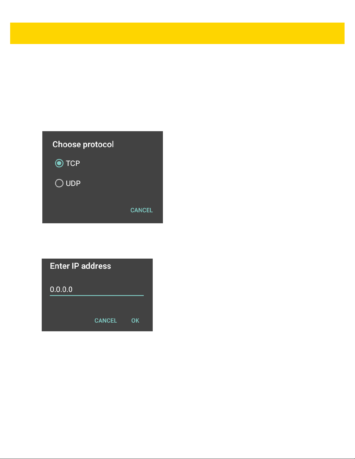
4 - 34 MC40 Mobile Computer Integrator Guide for AOSP Version 5.1.1
listens to TCP or UDP data coming fro m a configured port and IP address in the IP Output plug-in. To enable IP
Output to send captured data to a remote computer:
1. In IP Output, touch Enabled.
A check appears in the checkbox.
2. Ensure Remote Wedge option is disabled.
3. Touch Protocol.
4. In the Choose protocol dialog box, touch the same protocol selected in the client application. (TCP is the
default).
Figure 4-19 Protocol Selection
5. Touch IP Address.
6. In the Enter IP address dialog box, enter the IP address of host computer to send data to.
Figure 4-20 IP Address Entry
7. Touch Port.
8. In the Enter port number dialog box, enter the port number that the host computer application is listening on.
Page 83

Figure 4-21 Port Number Entry
9. Configure Advanced Data Formatting and Basic Data Formatting Plug-in if any required modification to be
done to captured data before sending to remote computer.
Generating Advanced Data Formatting Rules
The ADF plug-in applies rules (actions to be performed based o n defined criteria) to the data received via an input
plug-in before sending it to the output plug-in.
DataWedge Communication 4 - 35
• Rules - The ADF process plug-in consists of one or more rules. DataWedge formats the output data
according to the first matching rule. A rule is a combination of criteria and a set of actions to be performed,
upon fulfillment of the criteria set in the rule.
• Criteria - Criteria can be set according to Input plug-in, symbology, matching string within the data (at the
specified position) and/or data length. Received data must match the defined criteria in order for the data to
be processed.
• Actions - A set of procedures defined to format data. There are four types of actions which are for formatting
cursor movement, data modification, data sending and dela y specifications. An action can be defined to send
the first number of characters to the Output plug-in, pad the ou tput data with spaces or zeros, remove spaces
in data, etc.
Configuring ADF Plug-in
Configuring the ADF plug-in consists of creating a rule, defining the criteria and defining the actions.
1. Touch > DataWedge.
2. Touch a DataWedge profile.
3. In Keystroke Output, touch Advanced data formatting.
Page 84

4 - 36 MC40 Mobile Computer Integrator Guide for AOSP Version 5.1.1
Figure 4-22 Advanced Data Formatting Screen
4. Touch the Enable checkbox to enable ADF.
Creating a Rule
NOTE By default, Rule0, is the only rule in the Rules list.
1. Touch > New rule.
2. Touch the Enter rule name text box.
3. In the text box, enter a name for the new rule.
4. Touch OK.
Defining a Rule
1. Touch the newly created rule in the Rules list.
Page 85

DataWedge Communication 4 - 37
Figure 4-23 Rule List Screen
2. Touch the Rule enabled checkbox to enable the current rule.
Defining Criteria
1. Touch Criteria.
Page 86

4 - 38 MC40 Mobile Computer Integrator Guide for AOSP Version 5.1.1
Figure 4-24 Criteria Screen
2. Touch String to check for option to specify the string that must be present in the data.
3. In the Enter the string to check for dialog box, enter the string.
4. Touch OK.
5. Touch String position option to specify the position of the string specified in the String to check for option.
The ADF rule is only applied if the specific string in String to check for is found at the specified String
position location (zero for the start of the string).
6. Touch the + or - to change the value.
7. Touch OK.
8. Touch String length option to specify a length for th e received data . The ADF rule only applies to the bar code
data with that specified length.
9. Touch the + or - to change the value.
10. Touch OK.
11. Touch Source criteria option to associate an input device to an ADF rule. The ADF rule only applies to data
received from associated input devices.
12. Touch Barcode input or MSR input. Options vary depending upon the device configuration.
13. Touch the Source enabled checkbox to accept data from this source.
Page 87

DataWedge Communication 4 - 39
Figure 4-25 Barcode Input Screen
14. For Barcode inputs, touch the All decoders enabled checkbox to select all bar code symbologies. Deselect
the All decoders enabled checkbox to individually select the symbologies.
15. Touch until the Rule screen appears.
16. If required, repeat steps to create another rule.
17. Touch until the Rule screen appears.
Defining an Action
NOTE By default the Send remaining action is in the Actions list.
1. Touch > New action.
2. In the New action menu, select an action to add to the Actions list. See Table 4-2 on page 4-40 for a list of
supported ADF actions.
3. Some Actions require additional information. Touch the Action to display additional information fields.
4. Repeat steps to create more actions.
5. Touch .
6. Touch .
Deleting a Rule
1. Touch and hold on a rule until the context menu appears.
2. Touch Delete rule to delete the rule from the Rules list.
Page 88

4 - 40 MC40 Mobile Computer Integrator Guide for AOSP Version 5.1.1
NOTE When there is no rule available for ADF plug-in or all rules are disabled, DataWedge passes decoded data
to the output plug-in without processing the data.
Order Rules List
NOTE When there are no rules defined, ADF passes the captured data through as is. In contrast, when rules are
defined but all are disabled, ADF does not pass any captured data through.
Rules are processed in top-down order. The rules that are on top of the list are processed first. Use the icon next to
the rule to move it to another position in the list.
Table 4-2 ADF Supported Actions
Type Actions Description
Cursor
Movement
Skip ahead Moves the cursor forward by a specified number of characters. Enter
the number of characters to move the cur so r ah ea d .
Skip back Moves the cursor back by a specified number of characters. Enter the
number of characters to move the cursor back.
Skip to start Moves the cursor to the beginning of the data.
Move to Moves the cursor forward until the specified string is found. Enter the
string in the data field.
Move past a Moves the cursor forward past the specified string. Enter the string in
the data field.
Page 89

DataWedge Communication 4 - 41
Table 4-2 ADF Supported Actions (Continued)
Type Actions Description
Data
Modification
Crunch spaces Remove spaces between words to one and remove all spaces at the
beginning and end of the data.
Stop space crunch Stops space crunching. This disables the last Crunch spaces action.
Remove all spaces Remove all spaces in the data.
Stop space removal Stop removing spaces. This disables the last Remove all sp aces
action.
Remove leading zeros Remove all zeros at the beginning of data.
Stop zero removal Stop removing zeros at the beginning of da ta . This disables the
previous Remove leading zeros action.
Pad with zeros Left pad data with zeros to meet the specified length. Enter the
number zeros to pad.
Stop pad zeros Stop padding with zeros. This disables the previous Pad with zeros
action.
Pad with spaces Left pad data with spaces to meet the specified length. Enter the
number spaces to pad.
Stop pad spaces Stop padding with spaces. This disables the previous Pad with
spaces action.
Replace string Replaces a specified string with a new string. Enter the string to
replace and the string to replace it with.
Stop all replace string Stop all Replace string actions.
Data
Sending
Send next Sends the specified number of characters from the current cursor
position. Enter the number of characters to send.
Send remaining Sends all data that remains from the current cursor position.
Send up to Sends all data up to a specified string. Enter the string.
Send pause Pauses the specified number of milliseconds before continuing the
next action. Enter the amount of time in milliseconds.
Send string Sends a specified string. Enter the string to send.
Send char Sends a specified ASCII/ Unicode character . Ente r a character value.
The maximum Unicode character value can be entered is U-10FFFF
(= 1114111 in decimal).
Deleting an Action
1. Touch and hold the action name.
2. Select Delete action from the context menu.
ADF Example
The following illustrates an example of creating Advanced Data Formatting:
Page 90

4 - 42 MC40 Mobile Computer Integrator Guide for AOSP Version 5.1.1
When a user scans a bar code with the following criteria:
• Code 39 bar code.
• length of 12 characters.
• contains 129 at the start position.
Modify the data as follows:
• Pad all sends with zeros to length 8.
• send all data up to character X.
• send a space character.
To create an ADF rule for the above example:
1. Touch > DataWedge > Profile0.
2. Under Keystroke Output, touch Advanced data formatting.
3. Touch Enable.
4. Touch Rule0.
5. Touch Criteria.
6. Touch String to check for.
7. In the Enter the string to check for text box, enter 129 and then touch OK.
8. Touch String position.
9. Change the value to 0.
10. Touch OK.
11. Touch String length.
12. Change value to 12.
13. Touch OK.
14. Touch Source criteria.
15. Touch Barcode input.
16. Touch All decoders enabled to disable all decoders.
17. Touch Code 39.
18. Touch three times.
19. Touch Actions.
20. Touch and hold on the Send remaining rule until a menu appears.
21. Touch Delete action.
22. Touch > New action.
23. Select Pad with zeros.
24. Touch the Pad with zeros rule.
25. Touch How many.
26. Change value to 8 and then touch OK.
27. Touch .
28. Touch > New action.
Page 91

29. Select Send up to.
30. Touch Send up to rule.
31. Touch String.
32. In the Enter a string text box, enter X.
33. Touch OK.
34. Touch .
35. Touch > New action.
36. Select Send char.
37. Touch Send char rule.
38. Touch Character code.
39. In the Enter character code text box, enter 32.
40. Touch OK.
41. Touch .
DataWedge Communication 4 - 43
Figure 4-26 ADF Sample Screens
42. Ensure that an application is open on the device and a text field is in focus (text cursor in text field).
43. Aim the exit window at the bar code.
Page 92
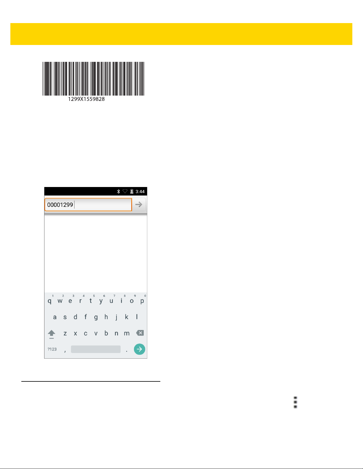
4 - 44 MC40 Mobile Computer Integrator Guide for AOSP Version 5.1.1
Figure 4-27 Sample Bar Code
44. Press and hold the scan button.
The red laser aiming pattern turns on to assist in aimi ng. Ensure that the bar code is within the area forme d by
the aiming pattern. The LED light red to indicate that data capture is in process.
45. The LED lights green and a beep sounds, by default, to indicate the bar code was decoded successfully.
Haptic Feedback is not enabled by default, so vibration will not work by default. The formatted data
000129X<space>appears in the text field.
Scanning a Code 39 bar code of 1299X15598 does not transmit data (rule is ignored) because the bar code
data did not meet the length criteria.
Figure 4-28 Formatted Data
DataWedge Settings
The DataWedge Settings screen provides access to general, non-profile related options. Touch > Settings.
Page 93

DataWedge Communication 4 - 45
Figure 4-29 DataWedge Settings Window
• DataWedge enabled - Enables or disables DataW edge. To disable DataWedge uncheck this option.
• Enable logging - Enables or disables debug output file to logcat. To enable logging check this option.
• Import - allows import of a DataWedge configuratio n file. The imported configuration replaces the current
configuration.
•Export - allows export of the current DataWedge configuration to the microSD card.
• Import Profile - allows import of a DataWedge profile file.
• Export Profile - allows export of a DataWedge profile.
•Restore - return the current configuration back to factory defaults.
Importing a Configuration File
1. Copy the configuration file to a location on the device (Internal Storage or microSD card
/Android/data/com.symbol.datawedge/files folder).
2. Touch > DataWedge.
3. Touch > Settings.
4. Touch Import.
5. In the Import datawedge.db from dialog box, select the location to import the configuration file from. Use .
.. and folder entries to browse to the configuration file. The configuration file (datawedge.db) is
and
imported and replaces the current configuration.
Page 94

4 - 46 MC40 Mobile Computer Integrator Guide for AOSP Version 5.1.1
Exporting a Configuration File
1. Touch > DataWedge.
2. Touch > Settings.
3. Touch Export.
4. In the Export to dialog box, select the location to store the file.
5. Touch Export. The configuration file (datawedge.db) is saved to the selected location.
Importing a Profile File
NOTE Do not change the filename of the of the profile file. If the filename is changed, the file will not be imported.
1. Copy the profile file to the root of the On Device Storage.
2. Touch > DataWedge.
3. Touch > Settings.
4. Touch Import Profile.
5. In the Import profile from dialog box, select the location to import the profile file from. Use .,and .., and folder
entries to locate the profile file. The profile file (dwprofile_x.db, where x = the name of the profile) is imported
and appears in the profile list.
Exporting a Profile
1. Touch > DataWedge.
2. Touch > Change to change the location to save the file.
3. Select Internal Storage or External Storage.
4. Touch OK.
5. Select a profile from the profile list.
6. Touch Export. The profile file (dwprofile_x.db, where x = name of the profile) is saved to the selected location.
Restoring DataWedge
To restore DataWedge to the factory de fault configuration:
1. Touch > DataWedge.
2. Touch > Settings.
3. Touch Restore.
4. Touch Yes.
Page 95

Configuration and Profile File Management
The configuration or profile settings for DataWe dge can be saved to a file for distribution to other devices.
After making configuration or profile changes, export the new configuration or profile to the root of the microSD
card. The configuration file created is automatically named datawedge.db. The profile file created is automatically
named dwprofile_x.db, where x is the profile name. The files can then the copied to the microSD card of other
devices and imported into DataWedge on those devices. Importing a configuration or profile replaces the existing
settings.
After making configuration or profile changes, export the new configuration or profile to the root of the On Device
Storage. The configuration file created is automatically named datawedge.db. The profile file created is
automatically named dwprofile_x.db, where x is the profile name. The files can then the copied to the On—device
Storage of other devices and imported into DataWedge on those devices. Importing a configuration or profile
replaces the existing settings.
Enterprise Folder
Internal storage contains the Enterprise folder (/enterprise). The Enterprise folder is persistent and maintains data
after an Enterprise reset. After an Enterprise Reset, DataWedge checks folder
/enterprise/device/settings/datawedge/enterprisereset/for a configuration file, datawedge.db or a profile file,
dwprofile_x.db. If the file is found, it imports the file to replace any existing configuration or profile.
DataWedge Communication 4 - 47
NOTE A Factory Reset deletes all files in the Enterprise folder.
Auto Import
DataWedge supports remote deployment of a configuration to a device, using tools such as MSP. DataWedge
monitors the /enterprise/device/settings/datawedge/autoimport folder for the DataWedge configuration file
(datawedge.db) or a profile file (dwprofile_x.db). When DataWedge launches it checks the folder. If a configuration
or profile file is found, it imports the file to replace any existing configuration or profile. Once the file has been
imported it is deleted from the folder.
While DataWedge is running it receives a notification from the system that a file has been placed into the
/enterprise/device/settings/datawedge/autoimport folder. When this occurs, DataWedge imports this new
configuration or profile, replacing the existing one and delete the file. DataWedge begins using the imported
configuration immediately.
NOTE A Factory Reset deletes all files in the Enterprise folder.
It is strongly recommended that the user exits DataWedge before remotely deploying any configuration or
profile. It is required that the file permissions are set to 666.
Programming Notes
The following paragraphs provide specific programming information when using DataWedge.
Page 96

4 - 48 MC40 Mobile Computer Integrator Guide for AOSP Version 5.1.1
Capture Data and Taking a Photo in the Same Application
To be able to capture bar code data and take a photo in the same applica tion:
• Create a Datawedge profile pertaining to the picture taking Activity in your application that disables scanning
and use standard Android SDK APIs to control the Camera.
• The default Datawedge profile takes care of the scanning in the application. You might want to create another
DataWedge profile that caters to any specific scanning needs, as so cia ted to yo ur Application's Activity
pertaining to scanning.
• DataWedge has an intent to enable or disable the bar code scanner if the user needs to control this
programatically. More details can be found at: http://techdocs.zebra.com/datawedge/5-0/guide/api/.
Disable DataWedge on MC40 and Mass Deploy
To disable DataWedge and deploy onto multiple MC40 devices:
1. Touch > DataWedge.
2. Touch > Settings.
3. Unselect the DataWedge enabled check box.
4. Export the DataWedge configuration. See Exporting a Configuration File on page 4-46 for instructions. See
Configuration and Profile File Management on page 4-47 for instructions for using the auto import feature.
Soft Scan Feature
DataWedge allows a native Android a pplication to progra mmatically start, stop, or toggle th e scan trigger state. The
application can issue an Android Broadcast Intent, to control the scanner, without requiring the scan button to be
pressed. The active DataWedge profile is required to control all the parameters during a scan operation.
The structure of the broadcast intent that resolves to the soft scan is:
action: “com.symbol.emdk.datawedge.api.ACTION_SOFTSCANTRIGGER”
extras: This is a String name/value pair that contains trigger state details.
name: “com.symbol.emdk.datawedge.api.EXTRA_PARAMETER”
value: “START_SCANNING” or “STOP_SCANNING” or “TOGGLE_SCANNING”
Sample
Intent sendIntent = new Intent();
sendIntent.setAction(“com.symbol.emdk.datawedge.api.ACTION_SOFTSCANTRIGGER”);
sendIntent.putExtra(“com.symbol.emdk.datawedge.api.EXTRA_PARAMETER”, “TOGGLE_SCANNING”);
sendBroadcast(sendIntent);
Page 97

CHAPTER 5 WLAN CONFIGURATION
The MC40 supports the following WLAN security options:
• Open
• Wireless Equivalent Privacy (WEP)
• Wi-Fi Protected Access (WPA)/WPA2 Personal (PSK)
• Extensible Authentication Protocol (EAP)
• Lightweight Extensible Authentication Protocol (LEAP)
• Protected Extensible Authentication Protocol (PEAP) - with Microsoft Challenge-Handshake
Authentication Protocol version 2 (MSCHAPv2) and Generic Token Card (GTC) authentication.
• EAP-Flexible Authentication via Secure Tunneling (FAST) - with MSCHAPv2 and GTC authentication.
• EAP-Transport Layer Security (TLS)
• EAP-TTLS - with Password Authentication Protocol (PAP), MSCHAP and MSCHAPv2 authentication.
Connecting to a Wi-Fi Network
NOTE By default, the network Proxy is set to None and the IP settings is set to DHCP. See Configuri ng for a
Proxy Server for setting connection to a proxy server and see Configuring the Device to Use a Static IP
Address for setting the device to use a static IP address.
1. Touch > Wi-Fi.
2. Slide the Wi-Fi switch to the On position. The device searches for WLANs in the area and di splays them in the
list. Open networks are indicated with and secur e networks are indicated with a lock .
3. Scroll through the list and touch the desired WLAN network.
Page 98

5 - 2 MC40 Mobile Computer Integrator Guide for AOSP Version 5.1.1
Figure 5-1 WLAN Network Security Dialog Boxes
Touch Show password checkbox to display password as it is entered.
4. For open networks, touch Connect or for secure networks enter the required password or other credentials
then touch Connect. See the system administrator for more information.
5. The MC40 obtains a network address and other required information from the ne twor k using the d ynamic host
configuration protocol (DHCP) protocol. To configure the MC40 with a fixed internet protocol (IP) address, see
Configuring Ethernet Static IP Address on page 5-5.
6. When the device connects to the network, the network name appears at the top of the list and Connected
appears below the network name.
Manually Adding a Wi-Fi Network
Manually add a Wi-Fi network if the network does not broadcast its name (SSID) or to add a Wi-Fi network when
out of range.
1. Touch > Wi-Fi.
2. Slide the Wi-Fi switch to the On position.
3. Touch > Add network.
Page 99

WLAN Communication 5 - 3
4. In the Network SSID text box, enter the name of the Wi-Fi network.
5. In the Security drop-down list, select the type of security. Options:
• None
•WEP
• WPA/WPA2 PSK
• 802.1x EAP.
6. If the network security is None, touch Save.
7. If the network security is WEP or WPA/WPA2 PSK, enter the required password and then touch Save.
8. If the network security is 802.1x EAP:
• Touch the EAP method drop-down list and select PEAP, TLS, TTLS, LEAP or FAST.
• Touch the Phase 2 authentication drop-down list and select an authentication method.
• If required, touch CA certificate and select a Certification Authority (CA) certificate. Note: Certificates are
installed using the Security settings.
• If required, touch User certificate and select a user certificate. Note: User certificates are installed using
the Security settings.
• If required, in the Identity text box, enter the username credentia ls.
• If desired, in the Anonymous identity text box, enter an anonymous identity username.
• If required, in the Password text box, enter the password for then given identity.
NOTE By default, the network Proxy is set to None and the IP settings is set to DHCP. See Configuring for a
Proxy Server on page 5-3 for setting connection to a proxy server and see Configuring Ethernet Static IP
Address on page 5-5 for setting the device to use a static IP address.
9. Touch Save. To connect to the saved network, touch and hold on the saved network and select Connect to
network.
10. Touch .
Configuring for a Proxy Server
A proxy server is a server that acts as an intermediary for requests from clients seeking resources from other
servers. A client connects to the proxy server, requesting some service, such as a file, connection, web page, or
other resource, available from a different server. The proxy server evaluates the request according to its filtering
rules. For example, it may filter traffic by IP address or protocol. If the request is validated by the filter, the proxy
provides the resource by connecting to the relevant server and requesting the service on behalf of the client.
It is important for enterprise customers to be ab le to set up secu re computing environm ents within their companies,
and proxy configuration is an essential part of doing that. Proxy configuration acts as a security barrier ensuring
that the proxy server monitors all traffic between the Internet and the intranet. This is normally an integral part of
security enforcement in corporate firewalls within intranets.
Page 100

5 - 4 MC40 Mobile Computer Integrator Guide for AOSP Version 5.1.1
Ethernet Settings
The following settings can be configured when using Ethernet communication:
• Proxy Settings
• Static IP.
Configuring Ethernet Proxy Settings
The MC40 includes Ethernet cradle drivers. The MC40 can conn ect to an Ethernet network using a third-party
Ethernet dongle. After connecting the MC40, configure the Ethernet connection:
1. Place the MC40 into the Ethernet cradle slot.
2. Touch > Ethernet.
3. Slide the switch to the ON position.
4. Touch > Advanced.
Figure 5-2 Ethernet Proxy Settings
5. Touch Enable HTTP Proxy.
6. In the Proxy hostname field, enter the proxy server address.
7. In the Proxy port field, enter the proxy server port number.
NOTE When entering proxy addresses in the Bypass proxy for field, do not use spaces or carriage returns
between addresses.
8. In the Bypass proxy for text box, enter addresses for web sites that do not require to go through the proxy
server. Use the separator “|” between addresses.
9. Touch Save.
10. Touch .
 Loading...