


MC3300XR SERIES
RFID Mobile Computers
Integrator Guide
Supplement
MN-003889-02EN Rev. A

Copyright
ZEBRA and the stylized Zebra head are trademarks of Zebra Technologies Corporation, registered in many
jurisdictions worldwide. All other trademarks are the property of their respective owners. ©2020 Zebra
Technologies Corporation and/or its affiliates. All rights reserved.
COPYRIGHTS & TRADEMARKS: For complete copyright and trademark information, go to
www.zebra.com/copyright
.
WARRANTY: For complete warranty information, go to www.zebra.com/warranty
END USER LICENSE AGREEMENT: For complete EULA information, go to www.zebra.com/eula.
For Australia Only
For Australia Only. This warranty is given by Zebra Technologies Asia Pacific Pte. Ltd., 71 Robinson Road, #0502/03, Singapore 068895, Singapore. Our goods come with guarantees that cannot be excluded under the
Australia Consumer Law. You are entitled to a replacement or refund for a major failure and compensation for any
other reasonably foreseeable loss or damage. You are also entitled to have the goods repaired or replaced if the
goods fail to be of acceptable quality and the failure does not amount to a major failure.
Zebra Technologies Corporation Australia’s limited warranty above is in addition to any rights and remedies you
may have under the Australian Consumer Law. If you have any queries, please call Zebra Technologies
Corporation at +65 6858 0722. You may also visit our website: www.zebra.com
terms.
Terms of Use
•
Proprietary Statement
This manual contains proprietary information of Zebra Technologies Corporation and its subsidiaries
(“Zebra Technologies”). It is intended solely for the information and use of parties operating and
maintaining the equipment described herein. Such proprietary information may not be used, reproduced,
or disclosed to any other parties for any other purpose without the express, written permission of Zebra
Technologies.
•
Product Improvements
Continuous improvement of products is a policy of Zebra Technologies. All specifications and designs are
subject to change without notice.
•
Liability Disclaimer
Zebra Technologies takes steps to ensure that its published Engineering specifications and manuals are
correct; however, errors do occur. Zebra Technologies reserves the right to correct any such errors and
disclaims liability resulting therefrom.
•
Limitation of Liability
.
for the most updated warranty
In no event shall Zebra Technologies or anyone else involved in the creation, production, or delivery of the
accompanying product (including hardware and software) be liable for any damages whatsoever
(including, without limitation, consequential damages including loss of business profits, business
interruption, or loss of business information) arising out of the use of, the results of use of, or inability to
use such product, even if Zebra Technologies has been advised of the possibility of such damages. Some
jurisdictions do not allow the exclusion or limitation of incidental or consequential damages, so the above
limitation or exclusion may not apply to you.
2

Revision History
Changes to the original manual are listed below:
Change Date Description
-01 Rev A 06/2020 Initial release.
-02 Rev A 10/2020 Updates:
•
Table 4 - MC32N0 PP Battery
•
Battery information
•
Added device features
•
Deleted feedback email (no longer applicable)
3

Table of Contents
Copyright ........................................................................................................................................... 2
For Australia Only ....................................................................................................................... 2
Terms of Use .................................................................................................................................... 2
Revision History ................................................................................................................................ 3
About This Guide
Introduction ....................................................................................................................................... 7
Configurations ................................................................................................................................... 7
Chapter Descriptions ...................................................................................................................... 10
Notational Conventions ................................................................................................................... 11
Related Documents ........................................................................................................................ 11
Service Information ......................................................................................................................... 12
Getting Started
Introduction ..................................................................................................................................... 13
RFID Technology Overview ............................................................................................................ 13
RFID Components .................................................................................................................... 14
Tags .......................................................................................................................................... 14
Antenna ..................................................................................................................................... 14
Radio Module ............................................................................................................................ 14
Features .......................................................................................................................................... 15
LED Indications ............................................................................................................................... 17
Setting Up the MC3300xR .............................................................................................................. 17
Accessories
Introduction ..................................................................................................................................... 18
MC3300xR Accessories .................................................................................................................. 18
Compatibility ................................................................................................................................... 21
Battery Comparison .................................................................................................................. 21
Battery Compatibility ................................................................................................................. 22
1-Slot USB Charge Cradle .............................................................................................................. 22
Charging the MC3300xR Battery .............................................................................................. 23
Charging an MC3300xR Spare Battery ..................................................................................... 24
Battery Charging in 1-Slot USB Charge Cradle ........................................................................ 24
Charging Temperature ........................................................................................................ 25
4

Table of Contents
5-Slot Charge Only ShareCradle .................................................................................................... 25
Charging the MC3300xR Battery .............................................................................................. 26
Battery Charging in the 5-Slot Charge Only ShareCradle ......................................................... 26
Charging Temperature ........................................................................................................ 26
5-Slot Ethernet ShareCradle ........................................................................................................... 27
Charging the MC3300xR Battery .............................................................................................. 27
Battery Charging in the 5-Slot Ethernet ShareCradle ............................................................... 28
Charging Temperature ........................................................................................................ 28
Daisy-chaining Ethernet ShareCradles ..................................................................................... 28
Ethernet Settings ................................................................................................................. 29
Configuring Ethernet Proxy Settings ................................................................................... 29
Configuring Ethernet Static IP Address ............................................................................... 30
Establishing Ethernet Connection ............................................................................................. 31
LED Indicators ........................................................................................................................... 32
4-Slot ShareCradle with 4-Slot Battery Charger ............................................................................. 32
Charging the MC3300xR Battery .............................................................................................. 33
Charging Spare Batteries .......................................................................................................... 33
Battery Charging in the 4-Slot ShareCradle with 4-Slot Battery Charger .................................. 33
Charging Temperature ........................................................................................................ 33
4-Slot Ethernet ShareCradle with 4-Slot Battery Charger ............................................................... 34
Charging the MC3300xR Battery .............................................................................................. 34
Charging Spare Batteries .......................................................................................................... 35
Battery Charging in the 4-Slot Ethernet ShareCradle with 4-Slot Battery Charger ................... 35
Charging Temperature ........................................................................................................ 35
Daisy-chaining Ethernet Cradles ............................................................................................... 35
Ethernet Settings ................................................................................................................. 36
Configuring Ethernet Proxy Settings ................................................................................... 36
Configuring Ethernet Static IP Address ............................................................................... 37
Establishing Ethernet Connection ............................................................................................. 38
LED Indicators ........................................................................................................................... 39
4-Slot Spare Battery Charger .......................................................................................................... 39
Charging Spare Batteries .......................................................................................................... 39
Battery Charging ....................................................................................................................... 40
Spare Battery Charging ....................................................................................................... 40
Charging Temperature ........................................................................................................ 40
20-Slot Spare Battery Charger ........................................................................................................ 40
Charging Spare Batteries .......................................................................................................... 41
Battery Charging ....................................................................................................................... 41
Spare Battery Charging ....................................................................................................... 41
Charging Temperature ........................................................................................................ 42
USB Charge Cable ......................................................................................................................... 43
Connecting the USB Charge Cable to Device .......................................................................... 43
Connecting the USB Charge Cable to Host Computer ............................................................. 44
Main Battery Charging ........................................................................................................ 45
Charging the Device .................................................................................................................. 45
Main Battery Charging ........................................................................................................ 45
Disconnecting the USB Charge Cable ...................................................................................... 46
MC33XX Charge Only Adapter ....................................................................................................... 47
Adapter Installation ................................................................................................................... 47
Charging Temperature ........................................................................................................ 49
MC3300xR Rubber Boot ................................................................................................................. 49
5

Table of Contents
Fabric Holster .................................................................................................................................. 50
Belt Strap .................................................................................................................................. 50
Shoulder Strap .......................................................................................................................... 51
Using the Belt Strap .................................................................................................................. 52
Using the Shoulder Strap .......................................................................................................... 53
Hand Strap ...................................................................................................................................... 55
Zebra RFID Mobile Application for Android
RFID Manager
Introduction ..................................................................................................................................... 58
Using the RFID Manager for Android .............................................................................................. 58
Connection Status ..................................................................................................................... 59
Reader Status ..................................................................................................................... 59
Client Application Status ..................................................................................................... 60
RFID Regulatory ....................................................................................................................... 61
Settings ..................................................................................................................................... 62
Firmware Update ....................................................................................................................... 65
Recovery Mode ......................................................................................................................... 67
RFID Manager Log .................................................................................................................... 68
Exporting Log Files ............................................................................................................. 68
StageNow
Introduction ..................................................................................................................................... 69
Creating Firmware Update Profile using StageNow ....................................................................... 69
Import RFID Manager into StageNow
Introduction ..................................................................................................................................... 74
Creating Firmware Update Profile using StageNow ....................................................................... 74
Troubleshooting
Introduction ..................................................................................................................................... 81
Troubleshooting the MC3300xR ..................................................................................................... 81
Technical Specifications
Introduction ..................................................................................................................................... 82
MC3300xR Technical Specifications .............................................................................................. 82
6

About This Guide
Introduction
The MC3300xR Integrator Guide Supplement provides the unique set up and operating procedures for MC3300xR.
This guide is intended as a supplement to the MC33XX Integrator Guide, p/n MN-003136-xx. Procedures common
to MC3300 products are addressed in the MC33XX Integrator Guide.
NOTE: Screens and windows pictured in this guide are samples and can differ from actual screens.
Configurations
Table 1 MC3300xR Configurations
Configuration Description
MC333U-GJ2EG4EU MC3330XR UHF RFID GUN, CIRCULAR ANTENNA, 802.11 A/B/G/N/AC,
SE4770 2D IMAGER, 29 KEY, EXTENDED CAPACITY BATTERY, GMS, 4GB
RAM / 32GB ROM, ETSI BANDS
MC333U-GJ2EG4IL MC3330XR UHF RFID GUN, CIRCULAR ANTENNA, 802.11 A/B/G/N/AC,
SE4770 2D IMAGER, 29 KEY, EXTENDED CAPACITY BATTERY, GMS, 4GB
RAM / 32GB ROM, ISRAEL ONLY
MC333U-GJ2EG4US MC3330XR UHF RFID GUN, CIRCULAR ANTENNA, 802.11 A/B/G/N/AC,
SE4770 2D IMAGER, 29 KEY, EXTENDED CAPACITY BATTERY, GMS, 4GB
RAM / 32GB ROM, FCC BANDS
MC333U-GJ3EG4EU MC3330XR UHF RFID GUN, CIRCULAR ANTENNA, 802.11 A/B/G/N/AC,
SE4770 2D IMAGER, 38 KEY, EXTENDED CAPACITY BATTERY, GMS, 4GB
RAM / 32GB ROM, ETSI BANDS
MC333U-GJ3EG4US MC3330XR UHF RFID GUN, CIRCULAR ANTENNA, 802.11 A/B/G/N/AC,
SE4770 2D IMAGER, 38 KEY, EXTENDED CAPACITY BATTERY, GMS, 4GB
RAM / 32GB ROM, FCC BANDS
MC333U-GJ4EA4CN MC3330XR UHF RFID GUN, CIRCULAR ANTENNA, 802.11 A/B/G/N/AC,
SE4770 2D IMAGER, 47 KEY, EXTENDED CAPACITY BATTERY, AOSP,
4GB RAM / 32GB ROM, CHINA ONLY
7

About This Guide
Table 1 MC3300xR Configurations
Configuration Description
MC333U-GJ4EG4EU MC3330XR UHF RFID GUN, CIRCULAR ANTENNA, 802.11 A/B/G/N/AC,
SE4770 2D IMAGER, 47 KEY, EXTENDED CAPACITY BATTERY, GMS, 4GB
RAM / 32GB ROM, ETSI BANDS
MC333U-GJ4EG4IN MC3330XR UHF RFID GUN, CIRCULAR ANTENNA, 802.11 A/B/G/N/AC,
SE4770 2D IMAGER, 47 KEY, EXTENDED CAPACITY BATTERY, GMS, 4GB
RAM / 32GB ROM, INDIA ONLY
MC333U-GJ4EG4JP MC3330XR UHF RFID GUN, CIRCULAR ANTENNA, 802.11 A/B/G/N/AC,
SE4770 2D IMAGER, 47 KEY, EXTENDED CAPACITY BATTERY, GMS, 4GB
RAM / 32GB ROM, JAPAN ONLY
MC333U-GJ4EG4US MC3330XR UHF RFID GUN, CIRCULAR ANTENNA, 802.11 A/B/G/N/AC,
SE4770 2D IMAGER, 47 KEY, EXTENDED CAPACITY BATTERY, GMS, 4GB
RAM / 32GB ROM, FCC BANDS
MC333U-GJ4EG4WR MC3330XR UHF RFID GUN, CIRCULAR ANTENNA, 802.11 A/B/G/N/AC,
SE4770 2D IMAGER, 47 KEY, EXTENDED CAPACITY BATTERY, GMS, 4GB
RAM / 32GB ROM, WORLDWIDE (902-928 MHZ EXCL. NA)
MC339U-GE2EG4EU MC3390XR UHF RFID GUN, LINEAR ANTENNA, 802.11 A/B/G/N/AC,
SE4850 EXTENDED RANGE 2D IMAGER, 29 KEY, EXTENDED CAPACITY
BATTERY, GMS, 4GB RAM / 32GB ROM, ETSI BANDS
MC339U-GE2EG4US MC3390XR UHF RFID GUN, LINEAR ANTENNA, 802.11 A/B/G/N/AC,
SE4850 EXTENDED RANGE 2D IMAGER, 29 KEY, EXTENDED CAPACITY
BATTERY, GMS, 4GB RAM / 32GB ROM, FCC BANDS
MC339U-GE3EG4EU MC3390XR UHF RFID GUN, LINEAR ANTENNA, 802.11 A/B/G/N/AC,
SE4850 EXTENDED RANGE 2D IMAGER, 38 KEY, EXTENDED CAPACITY
BATTERY, GMS, 4GB RAM / 32GB ROM, ETSI BANDS
MC339U-GE3EG4US MC3390XR UHF RFID GUN, LINEAR ANTENNA, 802.11 A/B/G/N/AC,
SE4850 EXTENDED RANGE 2D IMAGER, 38 KEY, EXTENDED CAPACITY
BATTERY, GMS, 4GB RAM / 32GB ROM, FCC BANDS
MC339U-GE4EA4CN MC3390XR UHF RFID GUN, LINEAR ANTENNA, 802.11 A/B/G/N/AC,
SE4850 EXTENDED RANGE 2D IMAGER, 47 KEY, EXTENDED CAPACITY
BATTERY, AOSP, 4GB RAM / 32GB ROM, CHINA ONLY
MC339U-GE4EG4EU MC3390XR UHF RFID GUN, LINEAR ANTENNA, 802.11 A/B/G/N/AC,
SE4850 EXTENDED RANGE 2D IMAGER, 47 KEY, EXTENDED CAPACITY
BATTERY, GMS, 4GB RAM / 32GB ROM, ETSI BANDS
MC339U-GE4EG4IN MC3390XR UHF RFID GUN, LINEAR ANTENNA, 802.11 A/B/G/N/AC,
SE4850 EXTENDED RANGE 2D IMAGER, 47 KEY, EXTENDED CAPACITY
BATTERY, GMS, 4GB RAM / 32GB ROM, INDIA ONLY
MC339U-GE4EG4JP MC3390XR UHF RFID GUN, LINEAR ANTENNA, 802.11 A/B/G/N/AC,
SE4850 EXTENDED RANGE 2D IMAGER, 47 KEY, EXTENDED CAPACITY
BATTERY, GMS, 4GB RAM / 32GB ROM, JAPAN ONLY
MC339U-GE4EG4US MC3390XR UHF RFID GUN, LINEAR ANTENNA, 802.11 A/B/G/N/AC,
SE4850 EXTENDED RANGE 2D IMAGER, 47 KEY, EXTENDED CAPACITY
BATTERY, GMS, 4GB RAM / 32GB ROM, FCC BANDS
8

About This Guide
Table 1 MC3300xR Configurations
Configuration Description
MC339U-GE4EG4WR MC3390XR UHF RFID GUN, LINEAR ANTENNA, 802.11 A/B/G/N/AC,
SE4850 EXTENDED RANGE 2D IMAGER, 47 KEY, EXTENDED CAPACITY
BATTERY, GMS, 4GB RAM / 32GB ROM, WORLDWIDE (902-928 MHZ
EXCL. NA)
MC339U-GF2EG4EU MC3390XR UHF RFID GUN, LINEAR ANTENNA, 802.11 A/B/G/N/AC,
SE4750MR 2D IMAGER, 29 KEY, EXTENDED CAPACITY BATTERY, GMS,
4GB RAM / 32GB ROM, ETSI BANDS
MC339U-GF2EG4US MC3390XR UHF RFID GUN, LINEAR ANTENNA, 802.11 A/B/G/N/AC,
SE4750MR 2D IMAGER, 29 KEY, EXTENDED CAPACITY BATTERY, GMS,
4GB RAM / 32GB ROM, FCC BANDS
MC339U-GF3EG4EU MC3390XR UHF RFID GUN, LINEAR ANTENNA, 802.11 A/B/G/N/AC,
SE4750MR 2D IMAGER, 38 KEY, EXTENDED CAPACITY BATTERY, GMS,
4GB RAM / 32GB ROM, ETSI BANDS
MC339U-GF3EG4US MC3390XR UHF RFID GUN, LINEAR ANTENNA, 802.11 A/B/G/N/AC,
SE4750MR 2D IMAGER, 38 KEY, EXTENDED CAPACITY BATTERY, GMS,
4GB RAM / 32GB ROM, FCC BANDS
MC339U-GF4EA4CN MC3390XR UHF RFID GUN, LINEAR ANTENNA, 802.11 A/B/G/N/AC,
SE4750MR 2D IMAGER, 47 KEY, EXTENDED CAPACITY BATTERY, AOSP,
4GB RAM / 32GB ROM, CHINA ONLY
MC339U-GF4EG4EU MC3390XR UHF RFID GUN, LINEAR ANTENNA, 802.11 A/B/G/N/AC,
SE4750MR 2D IMAGER, 47 KEY, EXTENDED CAPACITY BATTERY, GMS,
4GB RAM / 32GB ROM, ETSI BANDS
MC339U-GF4EG4US MC3390XR UHF RFID GUN, LINEAR ANTENNA, 802.11 A/B/G/N/AC,
SE4750MR 2D IMAGER, 47 KEY, EXTENDED CAPACITY BATTERY, GMS,
4GB RAM / 32GB ROM, FCC BANDS
MC339U-GF4EG4WR MC3390XR UHF RFID GUN, LINEAR ANTENNA, 802.11 A/B/G/N/AC,
SE4750MR 2D IMAGER, 47 KEY, EXTENDED CAPACITY BATTERY, GMS,
4GB RAM / 32GB ROM, WORLDWIDE (902-928 MHZ EXCL. NA)
MC339U-GF4EG4TH MC3390xR UHF RFID GUN, LINEAR ANTENNA, 802.11 A/B/G/N/AC,
SE4750MR 2D IMAGER, 47 KEY, Extended Capacity Battery, GMS, 4GB
RAM / 32GB ROM, THAILAND ONLY
MC339U-GF3EG4TH MC3390xR UHF RFID GUN, LINEAR ANTENNA, 802.11 A/B/G/N/AC,
SE4750MR 2D IMAGER, 38 KEY, Extended Capacity Battery, GMS, 4GB
RAM / 32GB ROM, THAILAND ONLY
MC339U-GE4EG4TH MC3390xR UHF RFID GUN, LINEAR ANTENNA, 802.11 A/B/G/N/AC,
SE4850 EXTENDED RANGE 2D IMAGER, 47 KEY, Extended Capacity
Battery, GMS, 4GB RAM / 32GB ROM, THAILAND ONLY
MC333U-GJ4EG4TH MC3330xR UHF RFID GUN, CIRCULAR ANTENNA, 802.11 A/B/G/N/AC,
SE4770 2D IMAGER, 47 KEY, Extended Capacity Battery, GMS, 4GB RAM /
32GB ROM, THAILAND ONLY
9

Table 1 MC3300xR Configurations
Configuration Description
MC333U-GJ4EG4SL MC3330xR UHF RFID GUN, CIRCULAR ANTENNA, 802.11 A/B/G/N/AC,
MC339U-GF4EG4SL MC3390xR UHF RFID GUN, LINEAR ANTENNA, 802.11 A/B/G/N/AC,
Chapter Descriptions
Topics covered in this guide are as follows:
• Getting Started provides information on RFID technology and MC3300xR LED indications.
• Zebra RFID Mobile Application for Android for Android refers to the new 123RFID Mobile Application.
• Accessories describes the available accessories and how to use them with MC3300xR.
• RFID Manager describes how to configure the Zebra RFID Manager Application for MC3300xR.
About This Guide
SE4770 2D IMAGER, 47 KEY, Extended Capacity Battery, GMS, 4GB RAM /
32GB ROM, SRI LANKA
SE4750MR 2D IMAGER, 47 KEY, Extended Capacity Battery, GMS, 4GB
RAM / 32GB ROM, SRI LANKA
• Troubleshooting describes cleaning, maintenance, and troubleshooting procedures.
• StageNow provides a reference to access this easy Wizard-based tool that allows even complex Staging
profiles to become simple to create.
• Import RFID Manager into StageNow provides instructions necessary to generate an RFID Firmware
update profile and import RFID CSP plug-in into the StageNow application.
• Troubleshooting provides troubleshooting solutions for potential problems during MC3300xR operation.
• Technical Specifications provides the technical specifications for MC3300xR.
10

Notational Conventions
The following conventions are used in this document:
• “RFID mobile computer” refers to MC3300xR.
• Bold text is used to highlight the following:
• Dialog box, window and screen names
• Drop-down list and list box names
• Check box and radio button names
• Icons on a screen
• Key names on a keypad
• Button names on a screen.
• Bullets (•) indicate:
• Action items
• Lists of alternatives
• Lists of required steps that are not necessarily sequential
• Sequential lists (e.g., those that describe step-by-step procedures) appear as numbered lists.
About This Guide
Related Documents
The following documents provide more information about the reader.
• MC3330xR Quick Reference Guide, p/n MN-003890-xx.
• MC3390xR Quick Reference Guide, p/n MN-003891-xx.
• Zebra RFID SDK for Android Developer Guide, p/n MN-003158-xx.
• 123RFID Mobile Application User Guide, p/n MN-003765-xx.
For the latest version of this guide and all guides, go to: zebra.com/support
.
11

Service Information
Manufacturing Label
MC3330xR
MC3390xR
If you have a problem with your equipment, contact Zebra Support Center for your region. Contact information is
available at: www.zebra.com/support
When contacting the Zebra Support Center, please have the following information available:
• Serial number of the unit (found on manufacturing label)
• Model number or product name (found on manufacturing label)
• Software type and version number.
Figure 1 Manufacturing Label
About This Guide
.
Zebra responds to calls by email or telephone within the time limits set forth in support agreements.
If the problem cannot be solved by the Zebra Support Center, the user may need to return the equipment for
servicing and will be given specific directions. Zebra is not responsible for any damages incurred during shipment if
the approved shipping container is not used. Shipping the units improperly can possibly void the warranty.
Remove the microSD card from the device before shipping for service.
If you purchased your product from a Zebra business partner, contact that business partner for support.
12

Getting Started
Host Computer
Tags
Mobile Computer
RF Wave and
Response
Wireless LAN/
BT/ActiveSync
Introduction
This chapter provides an overview of RFID technology and components, and describes the MC3300xR LED
indications.
RFID Technology Overview
RFID (Radio Frequency Identification) is an advanced automatic identification (Auto ID) technology that uses radio
frequency signals to identify tagged items. An RFID tag contains a circuit that can store data. This data may be
pre-encoded or can be encoded in the field. The tags come in a variety of shapes and sizes.
To read a tag, the mobile computer sends out radio frequency waves using its integrated antenna. This RF field
powers and charges the tags, which are tuned to receive radio waves. The tags use this power to modulate the
carrier signal. The reader interprets the modulated signal and converts the data to a format for computer storage.
The computer application translates the data into an understandable format.
Figure 2 RFID System Elements
13

Getting Started
RFID Components
Zebra RFID solutions offer low cost, long read range, and a high read rate. These features provide real time
end-to-end visibility of products and assets in the factory, distribution center, retail outlet, or other facility. The
MC3300xR’s RFID system consists of the following components:
Silicon-based RFID tags that attach to retail products, vehicles, trailers, containers, pallets, boxes, etc.
An integrated antenna that supports applications such as item level tracking and asset tracking.
An embedded radio module that powers and communicates with tags for data capture and provides host
connectivity for data migration.
Tags
Tags contain embedded chips that store unique information. Available in various shapes and sizes, tags, often
called transponders, receive and respond to data requests. Tags require power to send data.
There are several categories of tags based on the protocol they support, read/write memory, and power options:
Active RFID tags are powered by internal light-weight batteries, and also use these batteries to broadcast radio
waves to the reader.
Semi-passive RFID tags are also powered by internal light-weight batteries, but draw broadcasting power from the
reader.
Passive RFID tags are powered by a reader-generated RF field. These tags are much lighter and less expensive
than active tags, and are typically applied to less expensive goods.
Antenna
Antennas transmit and receive radio frequency signals.
Radio Module
The radio module communicates with the tags and transfers the data to a host computer. It also provides features
such as filtering, CRC check, and tag writing. The MC3300xR supports standard RFID tags as described by
EPCGlobalTM Class 1 Gen2 protocol.
14

Features
1
87
10
6
3
4
5
2
9
MC3330xR
1
87
10
6
34
5
2
9
11
MC3390xR
MC33X0xR
Figure 3 Parts on the Device - Side Views
Getting Started
Item Description
1 Display - Displays all information needed to operate the MC3330xR.
2 Scan Button - Initiates data capture when a scan application is enabled.
3 Keypad - Use to enter data and navigate on screen functions.
4 Power Button - Press and hold to turn on the MC3330xR. Press to turn on or off the screen. Press and
hold to select one of these options:
Power off - Turn off the device.
Reboot - Reboot the device when software stops responding.
Airplane mode - Disable all wireless connections.
Silent mode - All notifications are disabled except for alarms.
5 Microphone - Use for communications in Handset mode.
15

Getting Started
1
4
2
3
1
4
2
3
MC3330xR
MC3390xR
Item Description
6 Hand Strap - Use for securely holding the device.
7 Battery Release Latch - Release the battery from the device.
8 Trigger - Initiates data capture when a scan application is enabled.
9 RFID Module.
10 Charge LED Scan/Decode Status - Indicates the battery charge state while charging or the scan/decode
status.
11
NFC logo ( ) - Indicates Near Field Communication (NFC) support.
Figure 4 Parts on the Device - Bottom Views
Item Description
1 Battery - Provides power for operating the device.
2 Battery Release Latch - Release the battery from the device.
3 Speaker - Provides audio output for video and music playback.
4 Scanner Exit Window - Provides data capture using the scanner.
16

LED Indications
The Charge LED Indicator indicates the charge status.
Table 2 LED Charge Indicators
Status Indications
Off The battery is not charging.
Green Fast (20 ms) Tag read and/or write.
Green Slow (200 ms) Firmware update in progress.
Red (5 s); Green Slow (200 ms) Firmware recovery mode followed by firmware update.
Getting Started
The battery is not inserted correctly in the cradle or connected to a power
source.
Cradle is not powered.
Setting Up the MC3300xR
To start using the MC3300xR for the first time:
• Ensure the battery is installed
• Charge the MC3300xR
• Power on the MC3300xR
• Remove MC3300xR from charger
• Set the region and power level (using the RFID Manager Application, Demo Application, or the partner
application).
17

Accessories
Introduction
This chapter provides information on using the accessories for the device.
MC3300xR Accessories
The table below lists the accessories available for the MC3300xR.
Table 3 MC3300xR Accessories
Accessory Part Number Description
Cradles
1-Slot USB Charge Cradle with
Spare Battery Charger
5-Slot Charge Only ShareCradle CRD-MC33-5SCHG-01 Charge only. Charges up to five MC3300xR.
5-Slot Ethernet ShareCradle CRD-MC33-5SETH-01 Charges up to five MC3300xR and provides
4-Slot Charge ShareCradle with
4-Slot Battery Charger
CRD-MC33-2SUCHG-01 Charges the MC3300xR main battery and a
spare battery, and synchronizes the
MC3300xR with a host computer through a
USB connection. Requires power supply
(PWR-BGA12V50W0WW), DC line cord
(CBL-DC-388A1-01) and a country specific
grounded AC line cord.
Requires power supply
(PWR-BGA12V108W0WW), DC line cord
(CBL-DC-381A1-01) and a country specific
grounded AC line cord.
Ethernet communication for up to five devices.
Requires power supply
(PWR-BGA12V108W0WW), DC line cord
(CBL-DC-381A1-01) and a country specific
grounded AC line cord.
CRD-MC33-4SC4BC-01 Charge only. Charges up to four MC3300xR
and up to four spare batteries. Requires power
supply (PWR-BGA12V108W0WW), DC line
cord (CBL-DC-381A1-01) and a country
specific grounded AC line cord.
18

Accessories
Table 3 MC3300xR Accessories (Continued)
Accessory Part Number Description
4-Slot Ethernet ShareCradle with
4-Slot Battery Charger
Chargers
4-Slot Spare Battery Charger SAC-MC33-4SCHG-01 Charges up to four MC3300xR spare
20-Slot Spare Battery Charger SAC-MC33-20SCHG-01 Charges up to 20 MC3300xR spare batteries.
Power Supply PWR-BGA12V50W0WW Level VI power supply. Provides 12 VDC, 2.5A
CRD-MC33-4SE4BC-01 Charges up to four MC3300xR and up to four
spare batteries and provides Ethernet
communication for up to four MC3300xR.
Requires power supply
(PWR-BGA12V108W0WW), DC line cord
(CBL-DC-381A1-01) and a country specific
grounded AC line cord.
batteries. Requires power supply
(PWR-BGA12V50W0WW), DC line cord
(CBL-DC-388A1-01) and a country specific
grounded AC line cord.
Requires power supply
(PWR-BGA12V108W0WW), DC line cord
(CBL-DC-381A1-01) and a country specific
grounded AC line cord.
power to the 1-Slot USB Charge Cradle and
the 4-Slot Spare Battery Charger. Requires a
DC line cord (CBL-DC-388A1-01) and a
country specific grounded AC line cord.
Power Supply
Power Supply
Power Supply PWR-WUA5V12W0GB Provides 12 VDC, 2.5A power to the USB
Power Supply PWR-WUA5V12W0EU Provides 12 VDC, 2.5A power to the USB
Power Supply PWR-WUA5V12W0AU Provides 12 VDC, 2.5A power to the USB
PWR-BGA12V108W0WW
PWR-WUA5V12W0US
Level VI power supply. Provides 12 VDC, 2.5A
power to the 5-Slot Charge Only Cradle, 5-Slot
Ethernet Cradle, 5-Slot Charge Cradle with
4-Slot Battery Charger, 5-Slot Ethernet Cradle
with 4-Slot Battery Charger and 20-Slot
Battery Charger. Requires a DC line cord
(CBL-DC-381A1-01) and a country specific
grounded AC line cord.
Wall adapter; Provides 12 VDC, 2.5A power to
the USB Charge Cable. Includes plug adapter
for use in the United States.
Charge Cable. Includes plug adapter for use in
the European Union.
Charge Cable. Includes plug adapter for use in
the United Kingdom.
Charge Cable. Includes plug adapter for use in
Australia.
19

Accessories
Table 3 MC3300xR Accessories (Continued)
Accessory Part Number Description
Power Supply PWR-WUA5V12W0CN Provides 12 VDC, 2.5A power to the USB
Charge Cable. Includes plug adapter for use in
China.
Power Supply PWR-WUA5V12W0IN Provides 12 VDC, 2.5A power to the USB
Charge Cable. Includes plug adapter for use in
India.
US AC Line Cord 23844-00-00R Provides power to 3–wire power supplies
PWR-BGA12V50W0WW and
PWR-BGA12V108W0WW.
DC Line Cord CBL-DC-381A1-01 Provides power from the power supply
(PWR-BGA12V108W0WW) to the 5-Slot
Charge Only Cradle, 5-Slot Ethernet Cradle,
5-Slot Charge Cradle with 4-Slot Battery
Charger, 5-Slot Ethernet Cradle with 4-Slot
Battery Charger and 20-Slot Battery Charger.
DC Line Cord CBL-DC-388A1-01 Provides power from the power supply
(PWR-BGA12V150W0WW) to the 1-Slot USB
Charge Cradle and 4-Slot Battery Charger.
Cables
USB Charge Cable CBL-MC33-USBCHG-01 Provides power and/or communication over
USB to the device. Requires wall
adapter/power supply PWR-WUA5V12W0xx.
1-Slot Cradle USB Cable 25-124330-01R Provides USB communication through the
1-Slot USB cradle to the host computer.
Miscellaneous
Cradle Adapter ADP-MC33-CRDCUP-01 MC3300xR Charge Only Adapter for
backwards compatibility with MC32 cradles.
Works with MC32N0 1-Slot USB Cradle,
4-Slot Charge Only Cradle, and 4-Slot
Ethernet Cradles.
5200 mAh Battery (Extended
PowerPrecision+)
Hand Strap SG-MC33-HDSTPG-01 Replacement hand strap for the MC3300xR.
BTRY-MC33-52MA-01
BTRY-MC33-52MA-10
BTRY-MC33-52MA-IN
Replacement extended capacity battery.
Replacement extended capacity battery (10–
pack).
Replacement extended capacity battery
(India).
Hand strap loop holds an optional stylus
(SG-TC7X-STYLUS-03).
Fabric Holster SG-MC3021212–01R Provides a soft, clip on holster and a shoulder
strap for the MC3300xR.
Shoulder Strap 58-40000-007R Universal shoulder strap.
20

Accessories
Table 3 MC3300xR Accessories (Continued)
Accessory Part Number Description
Belt 11-08062-02R Belt for fabric holster.
Rubber Boot SG-MC33-RBTG-02
Tempered Glass Screen
Protector
Stylus and Tether SG-TC7X-STYLUS-03 Conductive carbon-filled stylus for capacitive
Compatibility
The table below displays compatibility between MC3300xR and MC32N0 and accessories.
Table 4 Compatibility
MC3300xR Yes No Yes Yes
MC32N0 No Yes No Yes N/A N/A
MC3300xR PP+ Battery N/A N/A Yes No Yes No
SG-MC33-RBTG-03
MISC-MC33-SCRN-01 Provides additional protection for display
MC3300xR
PP+
Batteries
MC32N0
PP
Batteries
Provides additional protection for wear and
tear of the MC3300xR.
(5-pack).
touch panel; includes coiled tether (3-pack).
MC3300xR
Cradles
MC32N0
Cradles
w/adapter
MC3300xR
Battery
Charger
N/A N/A
MC32N0
Battery
Charger
MC32N0 PP Battery N/A N/A Yes Yes Yes Yes
• MC3300xR is compatible with the MC3300xR PowerPrecision+ battery.
• MC3300xR is compatible with all cradles.
An additional adapter is needed to use any MC32N0 cradle slot, which provides charge only, no
communication.
• MC3300xR battery charger slots are compatible with all batteries (MC3300xR PowerPrecision+ and
MC32N0 PowerPrecision).
• MC32N0 are not compatible with MC3300xR cradles.
Battery Comparison
The table below displays a comparison of the MC3300xR batteries with the MC32N0 batteries.
Table 5 Battery Comparison
Feature MC32N0 MC3300xR
Battery Type PowerPrecision PowerPrecision+
Includes Zebra and PowerPrecision+ recessed logos No Yes
Back Label Grey Blue
21

Battery Compatibility
AC Line Cord
Power Supply
DC Line Cord
USB Cable
• MC3300xR PowerPrecision+ batteries are compatible with all MC3300xR and accessories.
• MC3300xR PowerPrecision+ batteries are not compatible with MC32N0 and accessories.
• MC32N0 PowerPrecision batteries are compatible with all MC32N0 and accessories.
• MC32N0 PowerPrecision batteries are compatible with MC3300xR charges and cradles.
1-Slot USB Charge Cradle
The 1-Slot USB Charge Cradle:
• Provides 9 VDC power for charging the mobile computer and charging the battery.
• Provides 4.2 VDC power to charge the spare battery.
• Provides a USB port for data communication between the mobile computer and a host computer or other
USB devices (e.g., a printer).
• Synchronizes information between the mobile computer and a host computer. With customized or third
party software, it can also synchronize the mobile computer with corporate databases.
• Compatible with the following batteries:
• MC3300xR 5200 mAh and 7000 mAh PowerPrecision+ extended batteries (only in spare battery slot).
Accessories
• MC32N0 5200 mAh PowerPrecision extended battery.
Figure 5 1-Slot USB Charge Cradle Setup
22

Accessories
Charging the MC3300xR Battery
NOTE: To function properly, remove the lower part of the rubber boot or the entire rubber boot before placing in
a charging cradle.
1. Ensure that the cradle is connected to power.
2. Slide the mobile computer into the slot in the cradle. The mobile computer Charge LED Indicator, indicates the
mobile computer battery charging status. For charging status, see Table 6 on page 24
Figure 6 MC3300xR Battery Charging
3. Gently press down on the device to ensure proper contact.
4. When charging is complete, remove the mobile computer from the cradle slot.
23

Accessories
Charging an MC3300xR Spare Battery
1. Ensure that the cradle is connected to power.
2. Insert the spare battery into the cradle, bottom first, and pivot the top of the battery down onto the contact pins.
Figure 7 MC3300xR Spare Battery Charging
3. Gently press down on the battery to ensure proper contact.
The Spare Battery Charging LED on the front of the cradle indicates the spare battery charging status.
4. When charging is complete, lift the battery out of the slot.
Battery Charging in 1-Slot USB Charge Cradle
The 1-Slot USB charge cradle charges the MC3300xR’s main battery and a spare battery simultaneously.
The MC3300xR’s Charge LED indicates the status of the battery charging in the MC3300xR. See Table 6 for
charging status indications.
The spare battery charging LED on the cradle indicates the status of the spare battery charging in the cradle. See
below for charging status indications.
Table 6 Spare Battery LED Charging Indicators
Spare Battery LED (on cradle) Indication
Off • The battery is not charging.
• The battery is not inserted correctly in the cradle or
connected to a power source.
• Cradle is not powered.
Solid Amber • Battery is charging.
Solid Green • Battery charging is complete.
24

Accessories
Table 6 Spare Battery LED Charging Indicators (Continued)
Spare Battery LED (on cradle) Indication
Fast Blinking Red
2 blinks/second
Solid Red • Spare battery is charging and battery is at the end
The MC3300xR 5200 mAh and 7000 mAh PowerPrecision+ extended batteries charge from 0% to 90% in less
than 3.8 hours at room temperature.
The MC32N0 5200 mAh PowerPrecision extended battery charges from 0% to 90% in less than 5.5 hours at room
temperature.
Charging error, e.g.:
• Temperature is too low or too high.
• Charging has gone on too long without completion
(typically eight hours).
of useful life.
• Charging complete and battery is at the end of
useful life.
Charging Temperature
Charge batteries in temperatures from 0 °C to 40 °C (32 °F to 104 °F). Charging is intelligently controlled by the
MC3300xR.
To accomplish this, for small periods of time, the MC3300xR or cradle alternately enables and disables battery
charging to keep the battery at acceptable temperatures. The MC3300xR or cradle indicates when charging is
disabled due to abnormal temperatures via its LED.
5-Slot Charge Only ShareCradle
The 5-Slot Charge Only ShareCradle:
• Provides 9 VDC power for operating the mobile computer and charging the battery.
• Simultaneously charges up to five mobile computers.
• Compatible with devices using the following batteries:
• MC3300xR 5200 mAh and 7000 mAh PowerPrecision+ extended batteries.
25

Accessories
AC Line Cord
DC Line Cord
Power Supply
Figure 8 5-Slot Charge Only ShareCradle Setup
Charging the MC3300xR Battery
NOTE: To function properly, remove the lower part of the rubber boot or the entire rubber boot before placing in
a charging cradle.
1. Ensure that the cradle is connected to power.
2. Slide the mobile computer into the slot in the cradle. The mobile computer Charge LED Indicator, indicates the
mobile computer battery charging status.
3. Gently press down on the device to ensure proper contact.
4. When charging is complete, remove the mobile computer from the cradle slot.
Battery Charging in the 5-Slot Charge Only ShareCradle
The MC3300xR’s Charge LED indicates the status of the battery charging in the MC3300xR. See Table 10 on
page 41 for charging status indications.
The MC3300xR 5200 mAh and 7000 mAh PowerPrecision+ extended batteries charges from 0% to 90% in less
than 3.8 hours at room temperature.
The MC32N0 5200 mAh PowerPrecision extended battery charges from 0% to 90% in less than 5.5 hours at room
temperature.
Charging Temperature
Charge batteries in temperatures from 0 °C to 40 °C (32 °F to 104 °F). Charging is intelligently controlled by the
MC3300xR.
To accomplish this, for small periods of time, the MC3300xR or cradle alternately enables and disables battery
charging to keep the battery at acceptable temperatures. The MC3300xR or cradle indicates when charging is
disabled due to abnormal temperatures via its LED.
26

5-Slot Ethernet ShareCradle
AC Line Cord
DC Line Cord
Power Supply
Primary PortEthernet Cable
Router
The 5-Slot Ethernet ShareCradle:
• Provides 9 VDC power for operating the mobile computer and charging the battery.
• Simultaneously charges up to five mobile computers.
• Compatible with devices using the following batteries:
• MC3300xR 5200 mAh and 7000 mAh PowerPrecision+ extended batteries.
• MC32N0 5200 mAh PowerPrecision extended battery.
Figure 9 5-Slot Ethernet ShareCradle Setup
Accessories
Charging the MC3300xR Battery
NOTE: To function properly, remove the lower part of the rubber boot or the entire rubber boot before placing in
a charging cradle.
1. Ensure that the cradle is connected to power.
2. Slide the mobile computer into the slot in the cradle. The mobile computer amber Charge LED Indicator,
indicates the mobile computer battery charging status.
3. Gently press down on the device to ensure proper contact.
4. When charging is complete, remove the mobile computer from the cradle slot.
27

Accessories
Battery Charging in the 5-Slot Ethernet ShareCradle
The MC3300xR’s Charge LED indicates the status of the battery charging in the MC3300xR. See Table 10 on
page 41 for charging status indications.
The MC3300xR 5200 mAh and 7000 mAh PowerPrecision+ extended batteries charges from 0% to 90% in less
than 3.8 hours at room temperature.
The MC32N0 5200 mAh PowerPrecision extended battery charges from 0% to 90% in less than 5.5 hours at room
temperature.
Charging Temperature
Charge batteries in temperatures from 0 °C to 40 °C (32 °F to 104 °F). Charging is intelligently controlled by the
MC3300xR.
To accomplish this, for small periods of time, the MC3300xR or cradle alternately enables and disables battery
charging to keep the battery at acceptable temperatures. The MC3300xR or cradle indicates when charging is
disabled due to abnormal temperatures via its LED.
Daisy-chaining Ethernet ShareCradles
Daisy-chain up to ten 5-Slot Ethernet ShareCradles to connect several cradles to an Ethernet network. Use either
a straight or crossover cable. Daisy-chaining should not be attempted when the main Ethernet connection to the
first cradle is 10 Mbps or throughput issues are likely to occur.
To daisy-chain 5-Slot Ethernet ShareCradles:
1. Connect power to each 5-Slot Ethernet ShareCradle.
2. Connect an Ethernet cable to one of the ports on the switch and the other end to the Primary Port of the first
cradle.
3. Connect an Ethernet cable to the Secondary port of the first cradle.
4. Connect the other end of the Ethernet cable to the Primary port of the next 5-Slot Ethernet ShareCradle.
28

Accessories
To Power Supply
To Next Cradle
To Power Supply
To Switch
Secondary Port
Primary Port
Figure 10 Daisy-chaining 5-Slot Ethernet ShareCradles
5. Connect additional cradles as described in step 3 and 4.
Ethernet Settings
The following settings can be configured when using Ethernet communication:
• Proxy Settings
• Static IP.
Configuring Ethernet Proxy Settings
The MC3300xR includes Ethernet cradle drivers. After inserting the MC3300xR, configure the Ethernet connection:
1. Swipe down from the status bar to open the quick access panel and then touch .
2. Touch Ethernet.
3. Slide the switch to the ON position.
4. Place the MC3300xR into the Ethernet cradle slot.
5. Touch and hold eth0 until the menu appears.
6. Touch Modify Proxy.
7. Touch the Proxy drop-down list and select Manual.
29

Accessories
Figure 11 Ethernet Proxy Settings
8. In the Proxy hostname field, enter the proxy server address.
9. In the Proxy port field, enter the proxy server port number.
NOTE: When entering proxy addresses in the Bypass proxy for field, do not use spaces or carriage returns
between addresses.
10. In the Bypass proxy for text box, enter addresses for web sites that do not require to go through the proxy
server. Use the separator “|” between addresses.
11. Touch MODIFY.
12. Touch .
Configuring Ethernet Static IP Address
The MC3300xR includes Ethernet cradle drivers. After inserting the MC3300xR, configure the Ethernet connection:
1. Swipe down from the status bar to open the quick access panel and then touch .
2. Touch Ethernet.
3. Slide the switch to the ON position.
4. Place the MC3300xR into the Ethernet cradle slot.
5. Touch eth0.
6. Touch Disconnect.
7. Touch eth0.
8. Touch the IP settings drop-down list and select Static.
30

Figure 12 Static IP Settings
Accessories
9. In the IP address field, enter the proxy server address.
10. If required, in the Gateway field, enter a gateway address for the device.
11. If required, in the Netmask field, enter the network mask address
12. If required, in the DNS address fields, enter a Domain Name System (DNS) addresses.
13. Touch CONNECT.
14. Touch .
Establishing Ethernet Connection
1. Swipe down from the status bar to open the quick access panel and then touch .
2. Touch Ethernet.
3. Slide the Ethernet switch to the ON position.
4. Insert the device into a slot.
The icon appears in the Status bar.
5. Touch eth0 to view Ethernet connection details.
31

Accessories
AC Line Cord
DC Line Cord
Power Supply
LED Indicators
There are two green LEDs on the side of the cradle. These green LEDs light and blink to indicate the data transfer
rate.
Table 7 LED Data Rate Indicators
Data Rate 1000 LED 100/10 LED
1 Gbps On/Blink Off
100 Mbps Off On/Blink
10 Mbps Off On/Blink
4-Slot ShareCradle with 4-Slot Battery Charger
The 4-Slot ShareCradle with 4-Slot Battery Charger:
• Provides 9 VDC power for operating the mobile computer and charging the battery.
• Provides 4.2 VDC power for charging spare batteries.
• Simultaneously charges up to four mobile computers and four spare batteries.
• Compatible with the following batteries:
• MC3300xR 5200 mAh and 7000 mAh PowerPrecision+ extended batteries.
• MC32N0 5200 mAh PowerPrecision extended battery.
Figure 13 4-Slot ShareCradle with 4-Slot Battery Charger Setup
32

Accessories
Charging the MC3300xR Battery
NOTE: To function properly, remove the lower part of the rubber boot or the entire rubber boot before placing in
a charging cradle.
1. Ensure that the cradle is connected to power.
2. Slide the mobile computer into the slot in the cradle. The mobile computer amber Charge LED Indicator,
indicates the mobile computer battery charging status.
3. Gently press down on the device to ensure proper contact.
4. When charging is complete, remove the mobile computer from the cradle slot.
Charging Spare Batteries
Insert the battery into the charger and gently press down on the battery to ensure proper contact.
Battery Charging in the 4-Slot ShareCradle with 4-Slot Battery Charger
The MC3300xR’s Charge LED or the spare battery LED indicates the status of the battery charging in the
MC3300xR. See Table 9 on page 40 for charging status indications.
The MC3300xR 5200 mAh and 7000 mAh PowerPrecision+ extended batteries charges from 0% to 90% in less
than 3.8 hours at room temperature.
The MC32N0 5200 mAh PowerPrecision extended battery charges from 0% to 90% in less than 5.5 hours at room
temperature.
Charging Temperature
Charge batteries in temperatures from 0 °C to 40 °C (32 °F to 104 °F). Charging is intelligently controlled by the
MC3300xR.
To accomplish this, for small periods of time, the MC3300xR or cradle alternately enables and disables battery
charging to keep the battery at acceptable temperatures. The MC3300xR or cradle indicates when charging is
disabled due to abnormal temperatures via its LED.
33

Accessories
AC Line Cord
DC Line Cord
Power Supply
Primary Port
Ethernet Cable
Router
4-Slot Ethernet ShareCradle with 4-Slot Battery Charger
The 4-Slot Ethernet ShareCradle with 4-Slot Battery Charger:
• Provides 9 VDC power for operating the mobile computer and charging the battery.
• Provides 4.2 VDC power for charging spare batteries.
• Simultaneously charges up to four mobile computers and four spare batteries.
• Compatible with the following batteries:
• MC3300xR 5200 mAh and 7000 mAh PowerPrecision+ extended batteries.
• MC32N0 5200 mAh PowerPrecision extended battery.
Figure 14 4-Slot Ethernet ShareCradle with 4-Slot Battery Charger Setup
Charging the MC3300xR Battery
NOTE: To function properly, remove the lower part of the rubber boot or the entire rubber boot before placing in
a charging cradle.
1. Ensure that the cradle is connected to power.
2. Slide the mobile computer into the slot in the cradle. The mobile computer amber Charge LED Indicator,
indicates the mobile computer battery charging status.
3. Gently press down on the device to ensure proper contact.
4. When charging is complete, remove the mobile computer from the cradle slot.
34

Accessories
Charging Spare Batteries
Insert the battery into the charger and gently press down on the battery to ensure proper contact.
Battery Charging in the 4-Slot Ethernet ShareCradle with 4-Slot Battery Charger
The MC3300xR’s Charge LED or the spare battery LED indicates the status of the battery charging in the
MC3300xR. See Table 9 on page 40 for charging status indications.
The MC3300xR 5200 mAh and 7000 mAh PowerPrecision+ extended batteries charges from 0% to 90% in less
than 3.8 hours at room temperature.
The MC32N0 5200 mAh PowerPrecision extended battery charges from 0% to 90% in less than 5.5 hours at room
temperature.
Charging Temperature
Charge batteries in temperatures from 0 °C to 40 °C (32 °F to 104 °F). Charging is intelligently controlled by the
MC3300xR.
To accomplish this, for small periods of time, the MC3300xR or cradle alternately enables and disables battery
charging to keep the battery at acceptable temperatures. The MC3300xR or cradle indicates when charging is
disabled due to abnormal temperatures via its LED.
Daisy-chaining Ethernet Cradles
Daisy-chain up to ten 5-Slot Ethernet ShareCradle with 4-Slot Battery Chargers to connect several cradles to an
Ethernet network. Use either a straight or crossover cable. Daisy-chaining should not be attempted when the main
Ethernet connection to the first cradle is 10 Mbps as throughput issues are likely to occur.
To daisy-chain 5-Slot Ethernet ShareCradle with 4-Slot Battery Chargers:
1. Connect power to each 5-Slot Ethernet ShareCradle with 4-Slot Battery Charger.
2. Connect an Ethernet cable to one of the ports on the switch and the other end to the Primary Port of the first
cradle.
3. Connect an Ethernet cable to the Secondary port of the first cradle.
4. Connect the other end of the Ethernet cable to the Primary port of the next 5-Slot Ethernet ShareCradle with
4-Slot Battery Charger.
35

Accessories
To Power Supply
To Next Cradle
To Power Supply
To Switch
Secondary Port
Primary Port
Figure 15 Daisy-chaining 5-Slot Ethernet ShareCradle with 4-Slot Battery Chargers
5. Connect additional cradles as described in step 3 and 4.
Ethernet Settings
The following settings can be configured when using Ethernet communication:
• Proxy Settings
• Static IP.
Configuring Ethernet Proxy Settings
The MC3300xR includes Ethernet cradle drivers. After inserting the MC3300xR, configure the Ethernet connection:
1. Swipe down from the status bar to open the quick access panel and then touch .
2. Touch Ethernet.
3. Slide the switch to the ON position.
4. Place the MC3300xR into the Ethernet cradle slot.
5. Touch and hold eth0 until the menu appears.
6. Touch Modify Proxy.
7. Touch the Proxy drop-down list and select Manual.
36

Accessories
Figure 16 Ethernet Proxy Settings
8. In the Proxy hostname field, enter the proxy server address.
9. In the Proxy port field, enter the proxy server port number.
NOTE: When entering proxy addresses in the Bypass proxy for field, do not use spaces or carriage returns
between addresses.
10. In the Bypass proxy for text box, enter addresses for web sites that do not require to go through the proxy
server. Use the separator “|” between addresses.
11. Touch MODIFY.
12. Touch .
Configuring Ethernet Static IP Address
The MC3300xR includes Ethernet cradle drivers. After inserting the MC3300xR, configure the Ethernet connection:
1. Swipe down from the status bar to open the quick access panel and then touch .
2. Touch Ethernet.
3. Slide the switch to the ON position.
4. Place the MC3300xR into the Ethernet cradle slot.
5. Touch eth0.
6. Touch Disconnect.
7. Touch eth0.
8. Touch the IP settings drop-down list and select Static.
37

Figure 17 Static IP Settings
Accessories
9. In the IP address field, enter the proxy server address.
10. If required, in the Gateway field, enter a gateway address for the device.
11. If required, in the Netmask field, enter the network mask address
12. If required, in the DNS address fields, enter a Domain Name System (DNS) addresses.
13. Touch CONNECT.
14. Touch .
Establishing Ethernet Connection
1. Swipe down from the status bar to open the quick access panel and then touch .
2. Touch Ethernet.
3. Slide the Ethernet switch to the ON position.
4. Insert the device into a slot.
The icon appears in the Status bar.
5. Touch eth0 to view Ethernet connection details.
38

LED Indicators
AC Line Cord
DC Line Cord
Power Supply
There are two green LEDs on the side of the cradle. These green LEDs light and blink to indicate the data transfer
rate.
Table 8 LED Data Rate Indicators
Data Rate 1000 LED 100/10 LED
1 Gbps On/Blink Off
100 Mbps Off On/Blink
10 Mbps Off On/Blink
4-Slot Spare Battery Charger
The 4-Slot Battery Charger:
• Charges up to four MC3300xR spare batteries.
• Provides 4.2 VDC power to charge the spare battery.
• Compatible with the following batteries:
Accessories
• MC3300xR 5200 mAh and 7000 mAh PowerPrecision+ extended batteries.
• MC32N0 5200 mAh PowerPrecision extended battery.
Charging Spare Batteries
1. Connect the charger to a power source.
2. Insert the battery into the charger and gently press down on the battery to ensure proper contact.
Figure 18 4-Slot Battery Charger Setup
39

Accessories
Battery Charging
Spare Battery Charging
Each Battery Charging LED indicates the status of the battery charging in each slot. The table below describes the
Battery Charging LED status.
Table 9 Battery LED Charging Indicators
LED Indication
Off • The battery is not charging.
• The battery is not inserted correctly in the cradle or
connected to a power source.
• Cradle is not powered.
Solid Amber • Battery is charging.
Solid Green • Battery charging is complete.
Fast Blinking Red
2 blinks/second
Solid Red • Spare battery is charging and battery is at the end
The MC3300xR 5200 mAh and 7000 mAh PowerPrecision+ extended batteries charges from 0% to 90% in less
than 3.8 hours at room temperature.
The MC32N0 5200 mAh PowerPrecision extended battery charges from 0% to 90% in less than 5.5 hours at room
temperature.
Charging error, e.g.:
• Temperature is too low or too high.
• Charging has gone on too long without completion
(typically eight hours).
of useful life.
• Charging complete and battery is at the end of
useful life.
Charging Temperature
Charge batteries in temperatures from 0 °C to 40 °C (32 °F to 104 °F). Charging is intelligently controlled by the
MC3300xR.
To accomplish this, for small periods of time, the changer alternately enables and disables battery charging to keep
the battery at acceptable temperatures. The charger indicates when charging is disabled due to abnormal
temperatures via its LED.
20-Slot Spare Battery Charger
The 20-Slot Battery Charger:
• Charges up to twenty MC3300xR spare batteries.
• Provides 4.2 VDC power to charge the spare battery.
40

Accessories
AC Line Cord
DC Line Cord
Power Supply
• Compatible with the following batteries:
• MC3300xR 5200 mAh and 7000 mAh PowerPrecision+ extended batteries.
• MC32N0 5200 mAh PowerPrecision extended battery.
Charging Spare Batteries
1. Connect the charger to a power source.
2. Insert the battery into the charger and gently press down on the battery to ensure proper contact.
Figure 19 20-Slot Battery Charger Setup
Battery Charging
Spare Battery Charging
Each Battery Charging LED indicates the status of the battery charging in each slot. The table below describes the
Battery Charging LED status.
Table 10 20-Slot Battery LED Charging Indicators
LED Indication
Off • The battery is not charging.
Solid Amber • Battery is charging.
Solid Green • Battery charging is complete.
• The battery is not inserted correctly in the cradle or
connected to a power source.
• Cradle is not powered.
41

Accessories
Table 10 20-Slot Battery LED Charging Indicators (Continued)
LED Indication
Fast Blinking Red
2 blinks/second
Solid Red • Spare battery is charging and battery is at the end
The MC3300xR 5200 mAh and 7000 mAh PowerPrecision+ extended batteries charges from 0% to 90% in less
than 5.5 hours at room temperature.
The MC32N0 5200 mAh PowerPrecision extended battery charges from 0% to 90% in less than 5.5 hours at room
temperature.
Charging error, e.g.:
• Temperature is too low or too high.
• Charging has gone on too long without completion
(typically eight hours).
of useful life.
• Charging complete and battery is at the end of
useful life.
Charging Temperature
Charge batteries in temperatures from 0 °C to 40 °C (32 °F to 104 °F). Charging is intelligently controlled by the
MC3300xR.
To accomplish this, for small periods of time, the changer alternately enables and disables battery charging to keep
the battery at acceptable temperatures. The charger indicates when charging is disabled due to abnormal
temperatures via its LED.
42

USB Charge Cable
The USB Charge Cable:
• Provides 5 VDC power to charge the battery.
• Provides power and/or communication with the host computer over USB to the device.
• Compatible with devices using the following batteries:
• MC3300xR 5200 mAh and 7000 mAh PowerPrecision+ extended batteries.
• MC32N0 5200 mAh PowerPrecision extended battery.
The USB Charge Cable snaps onto the bottom of the MC3300xR and removes e asily when not in use. When
attached to the MC3300xR allows charging only.
Figure 20 USB Charge Cable
Accessories
Connecting the USB Charge Cable to Device
NOTE: To function properly, remove the lower part of the rubber boot or the entire rubber boot before placing in
a charging cradle.
To connect the USB Charge Cable to the device, insert the USB Charge Cable straight onto the device until the
device touches the bottom of the cable cup.
43

Accessories
Figure 21 Connecting the USB Charge Cable
Connecting the USB Charge Cable to Host Computer
To connect the USB Charge Cable to a host computer:
1. Connect the USB Charge Cable to the MC3300xR.
2. Connect the USB connector of the cable to a host computer.
Figure 22 Connecting USB Charge Cable to Host Computer
44

Accessories
Main Battery Charging
The device’s Charging/Notification LED indicates the status of the battery charging in the device.
NOTE: Charging using a host computer USB port could take longer.
To achieve the best charging results, use only Zebra charging accessories and batteries. Charge
batteries at room temperature with the in sleep mode.
Charging the Device
To charge the device using the USB Charge Cable:
1. Connect the USB Charge Cable to the MC3300xR.
2. Connect the USB connector of the power supply.
3. Plug the power supply into a power outlet.
Figure 23 Charging the Device
Main Battery Charging
The device’s Charging/Notification LED indicates the status of the battery charging in the device.
NOTE: In many cases, the 90% charge provides plenty of charge for daily use.
To achieve the best charging results, use only Zebra charging accessories and batteries. Charge
batteries at room temperature with the MC3300xR
in sleep mode.
The MC3300xR 5200 mAh and 7000mAh PowerPrecision+ extended battery charges from 0% to 90% in less than
6 hours at room temperature.
The MC32N0 5200 mAh PowerPrecision extended battery charges from 0% to 90% in less than 6 hours at room
temperature.
45

Accessories
Disconnecting the USB Charge Cable
To disconnect the USB Charge Cable from the MC3300xR:
1. Grasp the cable cup in one hand (by pinching the front and back) and the device in the other hand.
2. Remove the device by pulling straight up.
Figure 24 Disconnecting the USB Charge Cable
46

MC33XX Charge Only Adapter
Use the MC33XX Charge Only Adapter for backwards compatibility with the MC32N0 cradles and the MC3300xR.
• MC33XX Charge Only Adapter supports the MC32N0 1-Slot USB Cradle, MC32N0 4-Slot Charge Only
Cradle, and MC32N0 4-Slot Ethernet Cradle.
• MC33XX Charge Only Adapter provides charge only; no communication when used with the MC32N0
cradles.
• MC32N0 1-Slot USB Cradle provides 5.4V DC to charge the device.
• MC32N0 1-Slot USB Cradle (with the MC33XX Charge Only Adapter) is compatible with an MC3300xR
Mobile Computer charging either an MC3300xR PowerPrecision+ extended battery or an MC32N0
PowerPrecision extended battery, but the MC32N0 1-Slot USB Cradle spare battery slot is only compatible
with the MC32N0 PowerPrecision batteries.
Adapter Installation
To install the MC33XX Charge Only Adapter into the MC32N0 Cradle:
1. Clean the MC32N0 cradle and contacts with an alcohol wipe, using a back and forth motion with your finger.
For more information about cleaning, see Troubleshooting.
Accessories
Figure 25 Clean MC32N0 Cradle
2. Peel and remove the adhesive from the back of the adapter.
Figure 26 Peel and Remove Adhesive
47

Accessories
3. Insert the adapter into the MC32N0 cradle and adhere to the bottom of the cradle.
Figure 27 Insert Adapter into Cradle and Adhere
4. Insert the MC3300xR device into the MC32N0 cradle.
Figure 28 Insert MC3300xR device into MC32N0 Cradle
The MC3300xR 5200 mAh and 7000mAh PowerPrecision+ extended battery charges from 0% to 90% in less than
5.5 hours at room temperature.
The MC32N0 5200 mAh PowerPrecision extended battery charges from 0% to 90% in less than 5.5 hours at room
temperature.
48

Charging Temperature
Charge batteries in temperatures from 0 °C to 40 °C (32 °F to 104 °F). Charging is intelligently controlled by the
MC3300xR.
To accomplish this, for small periods of time, the MC3300xR or cradle alternately enables and disables battery
charging to keep the battery at acceptable temperatures. The MC3300xR or cradle indicates when charging is
disabled due to abnormal temperatures via its LED.
MC3300xR Rubber Boot
The rubber boot provides additional protection for the MC3300xR.
NOTE: To function properly, remove the lower part of the rubber boot or the entire rubber boot before placing in
a charging cradle.
If the hand strap is attached, release the hand strap to install the rubber boot. After the rubber boot is
installed, reattach the hand strap.
To attach the rubber boot:
Accessories
1. If the hand strap is attached, remove the hand strap.
2. Slide the battery end of the MC3300xR into the bottom of the rubber boot.
Figure 29 Slide MC3300xR into Bottom of Rubber Boot
3. Grasp the top of the rubber boot and place over the top of the MC3300xR.
4. Re-attach the hand strap (see Hand Strap on page 55).
Figure 30 Place Rubber Boot Over Top of MC3300xR
49

Fabric Holster
The Fabric Holster provides a soft holder for the mobile computer. It consists of a fabric mobile computer holder, a
detachable shoulder strap and a belt strap See figures below to attach the Fabric Holster to a belt and shoulder
strap.
Belt Strap
Attach the Fabric Holster to a belt or waist band.
Figure 31 Attach the Fabric Holster to a Belt
Accessories
50

Shoulder Strap
Attach the fabric holster to a shoulder strap.
Figure 32 Attach Fabric Holster and Shoulder Strap
Accessories
o
51

Accessories
Using the Belt Strap
The Fabric Holster holds the MC3300xR on a belt or waist band.
1. Secure the Belt Strap over the belt or waistband and snap into place.
Figure 33 Secure Belt Strap On Belt
2. To insert the MC3300xR, slide the mobile computer (battery end first) into the Fabric Holster with the screen
facing the user.
Figure 34 Insert MC3300xR
3. Secure the MC3300xR with the restraining strap and place over the MC3300xR to secure in place.
52

Figure 35 Secure with Strap
Accessories
4. To remove the MC3300xR, unsnap the restraining strap to release. Lift the MC3300xR out of Fabric Holster.
Using the Shoulder Strap
1. Connect the clips on the shoulder strap to the rings on the fabric holster.
2. Place the shoulder strap over your head and rest on your shoulder.
53

Figure 36 Shoulder Strap
Accessories
3. Lift the strap and insert the MC3300xR into the holster.
4. Secure the strap to hold the MC3300xR in place.
54

Hand Strap
To install the hand strap:
1. Thread the lanyard loop through the opening near the base of the trigger handle.
Figure 37 Insert Loop Through Handle Slot
Accessories
2. Insert the top end of the hand strap through the loop.
Figure 38 Thread Hand Strap Through Loop
3. Thread the hand strap through the lanyard.
4. Pull the hand strap through the loop.
5. Thread the end of the hand strap with the tab through the slot on the bottom of the MC3300xR.
55

Figure 39 Thread Tab Through Slot
Accessories
6. Slide the tab through the slit in the hand strap so that the tip of the tab is facing away from the MC3300xR.
56

Zebra RFID Mobile Application for Android
The upgraded Zebra RFID Mobile Application is now called the 123RFID Mobile Application. For detailed
information about this app refer to the 123RFID Mobile Application User Guide, p/n MN-003765-xx. This guide
describes the app for Android and demonstrates the device’s capability and tag operation functionality.
The guide is available at: zebra.com/support
.
57

RFID Manager
Introduction
The Zebra RFID Manager application allows the user the perform various management functions on the RFID
reader module in the MC3300xR including firmware update, power control for the RFID Radio, resetting the RFID
module to factory defaults, and various other functions.
NOTE: Some screens shown in this guide may differ from the actual screens shown on the device. Screens are
subject to change with future releases.
Using the RFID Manager for Android
To use this application for RFID operations:
1. Launch the RFID Manager application for Android on the mobile device.
2. During initial use, set the region in which the device is operating. To set the region, open the application and
select Settings > Regulatory.
NOTE: If the RFID Demo application or partner application is connected to the MC3300xR, the RFID Manager
can still perform all management functions, however care should be used as to not interfere with any
ongoing operational behavior of the device (e.g., inventory, setting parameters, etc.).
58

RFID Manager
Connection Status
Reader Status
By default, the RFID Reader is powered on and in the Ready. If the MC3300xR’s RFID Radio is not powered on,
the Reader Status displays Off.
Figure 40 Reader Connection Status Screens
59

RFID Manager
Client Application Status
If the MC3300xR’s RFID Reader Status is Ready:
1. Launch the application manually.
2. On the Home Screen under Connection Status > Client Application, it indicates if the client application is
Connected or Disconnected to the MC3300xR’s RFID Reader.
Figure 41 Client Application Status Screens
The Battery Status contains the battery Charging Level percentage and the Charging Status (Charging or
Discharging).
60

RFID Manager
RFID Regulatory
To set the region, select the Regulatory arrow button to open the Regulatory screen. Select the Region and
Channel Selection settings and tap the Apply button. The Region drop-down displays the current region to which
the device is set. Choose the correct region before using the device.
NOTE: The Region and Channel Selection requires setup before the initial use only. However, if a Reset to
Factory Defaults operation is conducted on the MC3300xR’s RFID Reader, the operation removes the
Region and Channel and needs to be set again.
NOTE: Select only the country in which you are using the device.
• Channel Selection is allowed only for the regions that allow channel setting.
• Supported regions are those reported by the specific MC3300xR.
• If the region is not configured on the MC3300xR, the Regulatory status shows as NA.
• A customer application can also set the region and configuration programmatically.
Figure 42 Regulatory Screens
61

RFID Manager
Settings
To display Settings, select the Settings icon located on the bottom tool bar.
Turn on the Settings slider switch control to enable control of setting options.
Setting options are as follows:
• Temperature Notification – If enabled, a temperature high and critical notification appears with
temperature level indications.
• Reader Power Off/On - If enabled, the MC3300xR’s RFID Radio is powered on. When the MC3300xR’s
RFID radio is powered off, no RFID operations are supported.
Figure 43 Settings Screen
62
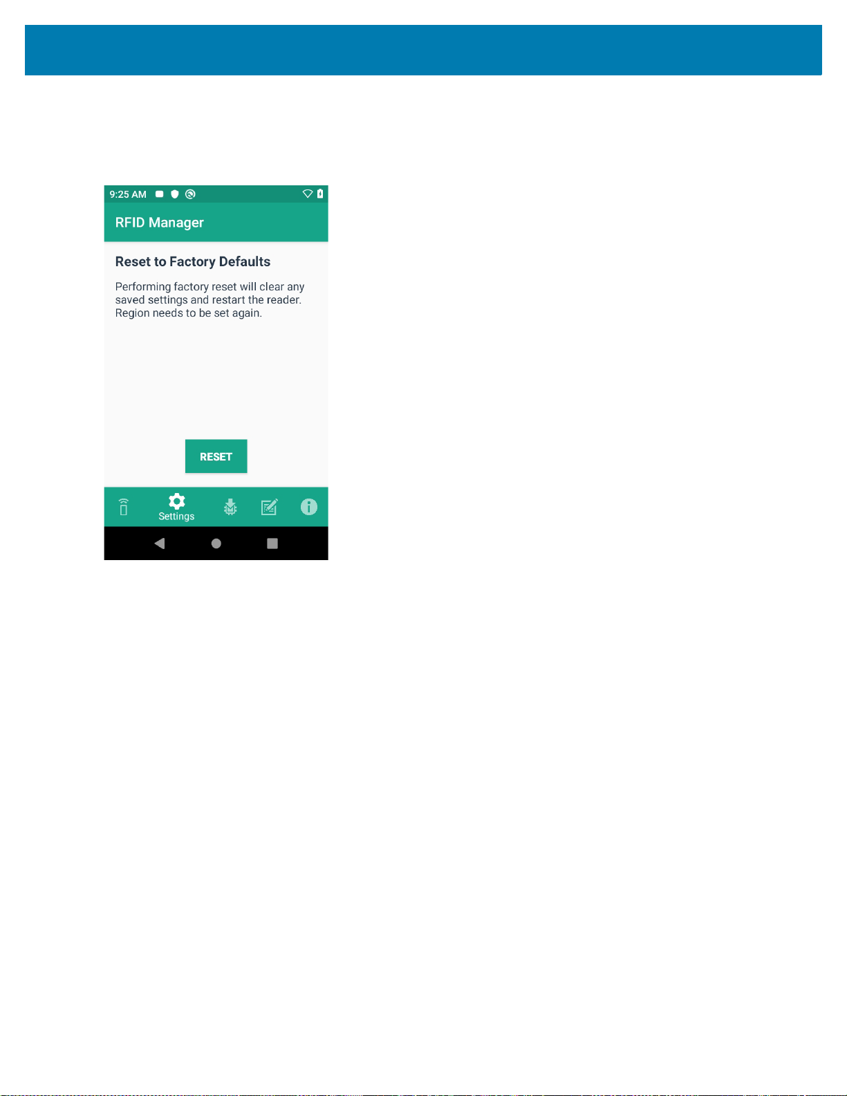
RFID Manager
• Reset to Factory Defaults - Select Reset to Factory Defaults to reset all configuration and region
settings to factory default settings. When selected, the RFID reader internally reboots and a window
message displays after successful operation.
Figure 44 Reset to Factory Defaults Screen
63

RFID Manager
• Reset Reader - Select Reset Reader to perform a reader restart. When selected, the reader reboots and
a window message displays after successful operation. Reader status confirmation is located under
Home > Status.
Figure 45 Reader Reset Screen
64

RFID Manager
Firmware Update
A product code update, bootloader, and radio update may be performed using the firmware update screen.
NOTE: More than 15% battery level is required to perform a Firmware Update.
To perform a firmware update:
1. Copy the RFD file into the MC3300xR’s SD card. One method is through the abd command (abd push
<firmware>/sdcard).
NOTE: The MC3300xR must have USB Debugging enabled in Developer Options for adb commands to work
properly.
2. Browse for the firmware RFD file, by clicking on the folder icon.
3. Select the required RFD file, from File View menu. When the file is selected, the application returns to update
screen.
Figure 46 Transferring Files for Firmware Update
65

RFID Manager
4. Click on the Update button.
Figure 47 RFID Manage Firmware Update Screen
5. Once Update is initiated, a status box displays that the firmware updates is in progress. For more information
on the current status of the Firmware update (including a progress bar), refer to the Android Notification bar.
6. After a successful update, a window displays a MC3300xR’s Firmware Installation Complete message.
Figure 48 Firmware Update Progress Window
66

RFID Manager
The updated firmware information is displayed on the Information screen.
Figure 49 Information Screen
Recovery Mode
Only select the Recovery Mode check box (see Figure 47 on page 66) if the MC3300xR’s firmware is suspected to
be corrupted. Contact the Zebra support team to use the Recovery Mode option.
67

RFID Manager
RFID Manager Log
The following options may be enabled to capture reader logs.
• Real-time Logs - Captures real time logs from the MC3300xR’s RFID radio.
• Retrieve Buffered Logs - Captures the buffered logs from the MC3300xR’s RFID radio.
• Debug Logs - Captures RFID System Service debug logs.
NOTE: All three logs can be enabled. If all three logs are disabled, default logs from the application is captured
which does not include MC3300xR’s RFID System Service logs.
Figure 50 RFID Manager Logger Screen
To capture real time logs:
1. Enable Real-time logs.
2. Connect and use the RFID application to create logs.
3. Tap on Export to retrieve the real time logs. It is not required to disconnect or exit the RFID application.
The Retrieve Buffered Logs option can only be used if the RFID application is not actively reading or writing RFID
tags.
The standard RX Logger application can also be used to get RFIDAPI3 and RFIDSERVICE activity.
Exporting Log Files
To export captured log files, select the Export button. The log file is saved as RfidLog.txt at a root of the
MC3300xR’s SD card file system. Retrieve the log file after connecting with PC through adb. RfidLog.txt file is
located in the internal storage of the root folder.
68

StageNow
Introduction
This chapter provides instruction necessary to generate a RFID Firmware update profile and import RFID CSP
plug-in into the StageNow application.
Creating Firmware Update Profile using StageNow
The following provides an example for creating a profile to copy SAADXS00-001-N13.rfd from the staging server to
the device and then subsequently updating the firmware.
To create a new update firmware profile:
1. Ensure both the device to be staged and the staging server are connected and accessible through the network.
2. Select Create New Profile from the side menu.
Figure 51 Create Firmware Update - CSP Library Screen
69

StageNow
3. Select XpertModeand tap on Create from the Select a Wizard window.
Figure 52 Wizard Window Selection
4. Enter a new profile name (For example, Rfid-N13-update as shown in Figure 90) and tap on Start.
Figure 53 Create Firmware Update - Profile Name
70

StageNow
5. Click on Addto add the FileMgr CSPand rfidmanager CSP.
Figure 54 Create Firmware Update - Add Applications
6. Enter the Target Path(target path in the device) and the Source File URL(select the file path in the
stagingserver) as shown in Figure 92 and tap Continue.
Figure 55 Create Firmware Update - FileMgr Configurations
71

StageNow
7. Select the UpdateFirmware action under RFID action list and enter the Target Path and File Nameentered
previously (/data/tmp/public/SAADXS00-001-N13D0.rfd) and tap Continue.
Figure 56 Create Firmware Update - RfidManager Configuration
8. Review your input and tap on CompleteProfile.
9. Select the Barcode Typecheck box required and click on Test.
Figure 57 Create Firmware Update - Barcode selection
72

StageNow
10. The test generates a barcode which can be scanned using the StageNow client on the device to stage the
firmware.
Figure 58 Stage Firmware Barcode
73

Import RFID Manager into StageNow
Introduction
This chapter provides instruction necessary to generate a RFID Firmware update profile and import RFID CSP
plug-in into the StageNow application.
Creating Firmware Update Profile using StageNow
In the following provides an example for creating a profile to copy SAADXS00-001-N10D0.DAT from the staging
server to the device and then subsequently updating the firmware.
To create a new update firmware profile:
1. Ensure both the device to be staged and the staging server are connected and accessible through the network.
Figure 59 Create Firmware Update-CSP Library Screen
2. Select Create New Profile from the side menu.
3. Select XpertMode and tap on Create from the Select a Wizard window.
74

Import RFID Manager into StageNow
Figure 60 Wizard Window Selection
4. Enter a new profile name (For example, Rfid-N10-update as shown in Figure 61) and tap on Start.
Figure 61 Create Firmware Update-Profile Name
75

Import RFID Manager into StageNow
5. Click on Add to add the FileMgr CSP and rfidmanager CSP.
Figure 62 Create Firmware Update-Add Applications
76

Import RFID Manager into StageNow
6. Enter the Target Path (target path in the device) and the Source file URL (select file path in the staging
server) as shown in Figure 63 and click Continue.
Figure 63 Create Firmware Update-FileMgr Configuration
77

Import RFID Manager into StageNow
7. Select the Firmware Update check-box and enter the Target Path and File Name entered previously
(/data/tmp/public/SAADXS00-001-N10D0.DAT) and tap Continue.
Figure 64 Create Firmware Update-RfidManager Configuration
78

Import RFID Manager into StageNow
8. Review your input and tap on Complete Profile.
9. Select the Barcode Type check box required and click on Test.
Figure 65 Create Firmware Update-Barcode selection
79

Import RFID Manager into StageNow
10. Test generates a barcode which can be scanned using the StageNow client on the device to stage the
firmware.
Figure 66 Stage Firmware Barcode
80

Troubleshooting
Introduction
This chapter provides troubleshooting solutions for potential problems. For more detailed device and accessory
troubleshooting, refer to the MC33XX Mobile Computer Integrator Guide at: www.zebra.com/support.
Troubleshooting the MC3300xR
Table 11 Troubleshooting the MC3300xR
Symptom Possible Cause Action
RFID Reader does not
read tags.
RFID Reader version is
not displayed in RFID
Manager.
RFID Reader is
responsive but cannot
read tags.
The RF region
configuration is not set.
Recovery mode is
enabled.
Battery is critically low.
Reader does not
function if battery level
is less than or equal to
5%.
Use the RFID Manager application to set the regulatory
region or country operation per the application
instructions.
Reboot device.
Place the RFID reader in the charging cradle until the
battery is charged.
81

Technical Specifications
Introduction
The following sections provide technical specification for the device.
MC3300xR Technical Specifications
The following table summarizes the MC3300xR’s intended operating environment and technical hardware
specifications.
Table 12 MC3300xR Technical Specifications
Item Description
Physical Characteristics
Dimensions MC3390xR:
6.45 in. L x 3.78 in. W x 10.67 in. D
164 mm L x 96 mm W x 271 mm D
MC3330xR:
6.45 in. L x 2.95 in. W x 8.31 in. D
164 mm L x 75 mm W x 211 mm D
Weight (with extended battery) MC3390xR with SE4750: 743g
MC3390xR with SE4850: 768 g
MC3330xR with SE4770: 676 g
Display 4.0 inch capacitive; WVGA; color
Imager Window Corning® Gorilla® Glass
Touch Panel Corning® Gorilla® Glass touch panel w/air gap
Backlight LED backlight
Battery Standard: Rechargeable Lithium-Ion 7000 mAh minimum (3.7V)
Expansion Slot User accessible microSD slot. Supports up to 32 GB microSDHC.
82

Specifications
Table 12 MC3300xR Technical Specifications (Continued)
Item Description
Network Connections USB 2.0 High Speed (host and client), WLAN and Bluetooth
Notification Side LEDs and audible tone.
Keypad Options 29-key Numeric
38-key Function Numeric (calculator-style integrated numeric
keypad)
47-key Alpha-Numeric (calculator-style integrated numeric
keypad)
Voice PTT Voice Support (Internal Speaker)
Audio Speaker
Performance Characteristics
CPU Qualcomm SD660
Operating System Android Q
Memory 4 GB RAM/32 GB Flash.
Output Power (USB) USB: 5 VDC @ 500 mA max.
User Environment
Operating Temperature -20°C to 50°C (-4°F to 122°F)
Storage Temperature -40°C to 70°C (-40°F to 158°F) without battery
Charging Temperature 0°C to 40°C (32°F to 104°F)
Humidity 5% to 95% RH non-condensing
Drop Specification Multiple 1.5 m (5 ft.) drops to concrete over the entire operating
temperature range.
Tumble Specification 1,000 1.6 ft./0.5 m tumbles (hits)
Sealing IP54
Vibration 5 Hz to 2 KHz
Thermal Shock -40°C to 70°C (-40°F to 158°F)
Electrostatic Discharge (ESD) ±20 kVdc air discharge, ± 10 kVdc contact discharge
Wireless LAN Data Communications
Wireless Local Area Network (WLAN) radio
Data Rates Supported 2.4 GHz: 144 Mbps
Operating Channels Chan 36 - 165 (5 GHz), Chan 1 - 13 (2.4 GHz); actual operating
®
IEEE
802.11a/b/g/n/ac/d/h/i/k/r/w
5 GHz: 867 Mbps
channels/frequencies depend on regulatory rules and certification
agency.
83

Specifications
Table 12 MC3300xR Technical Specifications (Continued)
Item Description
Security and Encryption Security Modes: WPA and WPA2 (Personal or Enterprise)
Encryption: WEP40/WEP104, TKIP and AES
Authentication: EAP-TLS; EAP-TTLS (MSCHAP, MSCHAPv2,
PAP); PEAP (MSCHAPv2, EAP-GTC); LEAP
Other: Wi-Fi certified, and supports IPv6
Certifications 802.11n/ac, WMM-PS, WMM-AC, PMF, Voice Enterprise, Wi-Fi
Direct, WPS
Fast Roam PMKID/OKC/CCKM/802.11r
Wireless PAN Data
Bluetooth V4.1, V2.1 + EDR w/ Bluetooth Low Energy (BLE). Class 2
Data Capture
Scanning MC3390xR: SE4750-MR 2D, SE4850-ER
MC3330xR: SE-4770
RFID
Standards Supported EPC Class 1Gen2; EPC Gen2 V2;;ISO-18000-63
RFID Engine Zebra Proprietary Radio Technology
Fastest Read Rate 900+ tags/sec
Nominal Read Range MC3390xR: ~60+ ft/~18.2+ m
MC3330xR: ~19.7+ ft/~6+ m
RFID Power Output 0 dBm to +30 dBm
RFID Antenna Type MC3390xR: Integrated Linear Polarized
MC3330xR: Integrated Circular Polarized
Frequency Range 865-928 MHz
*Specific regional and country settings supported upon country
selection
2D Imager Engine (SE4770) Specifications
Field of View Horizontal - 48°
Vertical - 30°
Image Resolution 1280 horizontal X 800 vertical pixels
Roll 360°
Pitch Angle +/- 60° from normal
Skew Tolerance +/- 60° from normal
Ambient Light Sunlight: 10,000 ft. candles (107,639 lux)
Focal Distance From front of engine: 17.7 cm (7.0 in.)
84

Specifications
Table 12 MC3300xR Technical Specifications (Continued)
Item Description
Laser Aiming Element Visible Laser Diode (VLD): 655 nm +/- 10 nm
Central Dot Optical Power: 0.6 mW (typical)
Pattern Angle: 48.0º horizontal, 38.0º vertical
2D Imager Engine (SE4750MR) Specifications
Field of View Horizontal - 31.0°
Vertical - 23°
Image Resolution 1280 horizontal X 960 vertical pixels
Roll 360°
Pitch Angle +/- 60° from normal
Skew Tolerance +/- 60° from normal
Ambient Light 96,900 lux
Focal Distance From front of engine: 36.0 cm (14.2 in.)
Laser Aiming Element Visible Laser Diode (VLD): 655 nm +/- 10 nm
Central Dot Optical Power: 0.6 mW (typical)
Pattern Angle: 48.0º horizontal, 38.0º vertical
Illumination System LEDs: Warm white LED
Pattern Angle: 80° at 505 intensity
2D Extended Range Imager Engine (SE4850) Specifications
Field of View Near camera: Horizontal - 32.0°, Vertical 20°
Far camera: Horizontal - 12°, Vertical - 7.6°
Image Resolution 1280 horizontal X 800 vertical pixels
Roll 360°
Pitch Angle +/- 60° from normal
Skew Tolerance +/- 60° from normal
Ambient Light Sunlight: 10,000 ft. candles (107,639 lux)
Laser Aiming Element Laser Wavelength: 655 nm
Central Dot Optical Power: 0.6 mW (Class 2 IEC60825:2014)
Illumination System LEDs: Hyper Red 660nm
85

Specifications
Table 12 MC3300xR Technical Specifications (Continued)
Item Description
Supported Symbologies
1D Chinese 2 of 5, Codabar, Code 11, Code 128, Code 39, Code 93,
Discrete 2 of 5, EAN-8, EAN-13, GS1 DataBar, GS1 DataBar
Expanded, GS1 DataBar Limited, Interleaved 2 of 5, Korean 2 of
5, MSI, TLC 39, Matrix 2 of 5, Trioptic, UPCA, UPCE, UPCE1,
Web Code.
2D Australian Postal, Aztec, Canadian Postal, Composite AB,
Composite C, Data Matrix, Dutch Postal, Japan Postal,
Maxicode, Micro PDF, Micro QR, PDF, QR Code, UK Postal, US
Planet, US Postnet, US4State, US4State FICS.
86

Index
Numerics
123RFID mobile application . . . . . . . . . . . . . . . . . . . . 57
1-slot USB charge cradle . . . . . . . . . . . . . . . . . . . . . . . 22
20-slot spare battery charger . . . . . . . . . . . . . . . . . . . . 40
4-slot spare battery charger . . . . . . . . . . . . . . . . . . . . . 39
5-slot charge only cradle . . . . . . . . . . . . . . . . . . . . . . . 25
5-slot cradle with 4-slot battery charger . . . . . . . . . . . . 32
5-slot ethernet cradle . . . . . . . . . . . . . . . . . . . . . . . . . . 27
5-slot ethernet cradle with 4-slot battery charger . . . . 34
A
accessories . . . . . . . . . . . . . . . . . . . . . . . . . . . . . . . . . 18
belt strap . . . . . . . . . . . . . . . . . . . . . . . . . . . . . . . . 50
fabric holster . . . . . . . . . . . . . . . . . . . . . . . . . . . . . 50
shoulder strap . . . . . . . . . . . . . . . . . . . . . . . . . . . . 51
adapter
installation . . . . . . . . . . . . . . . . . . . . . . . . . . . . . . . 47
B
battery
4-slot battery charging . . . . . . . . . . . . . . . . . . . . . 33
5-slot battery charging . . . . . . . . . . . . . . . . . . . . . 26
battery comparison . . . . . . . . . . . . . . . . . . . . . . . . 21
battery compatibility . . . . . . . . . . . . . . . . . . . . . . . 22
charging . . . . . . . . . . . . . . . . . . . . . . . . . . . . . . . . 23
charging 1-slot . . . . . . . . . . . . . . . . . . . . . . . . . . . 24
spare battery charging . . . . . . . . . . . . . . . . . . . . . 24
C
charge only adapter . . . . . . . . . . . . . . . . . . . . . . . . . . . 47
charging
5-slot sharecradle . . . . . . . . . . . . . . . . . . . . . . . . . 25
compatibility . . . . . . . . . . . . . . . . . . . . . . . . . . . . . . . . . 21
configurations . . . . . . . . . . . . . . . . . . . . . . . . . . . . . . . . 7
cradles
daisy-chaining ethernet cradles . . . . . . . . . . . . . . 35
D
documents . . . . . . . . . . . . . . . . . . . . . . . . . . . . . . . . . . 11
E
ethernet
configure static IP address . . . . . . . . . . . . . . . . . . 30
configuring ethernet . . . . . . . . . . . . . . . . . . . . . . . 29
establish connection . . . . . . . . . . . . . . . . . . . . . . . 31
F
features . . . . . . . . . . . . . . . . . . . . . . . . . . . . . . . . . 15, 16
L
label . . . . . . . . . . . . . . . . . . . . . . . . . . . . . . . . . . . . . . . 12
led
indicators . . . . . . . . . . . . . . . . . . . . . . . . . . . . . . . 32
M
manufacturing Label . . . . . . . . . . . . . . . . . . . . . . . . . . 12
mc3300r
initial setup . . . . . . . . . . . . . . . . . . . . . . . . . . . . . . 17
technical specifications . . . . . . . . . . . . . . . . . . . . . 82
R
revision history . . . . . . . . . . . . . . . . . . . . . . . . . . . . . . . 3
rfid
antenna . . . . . . . . . . . . . . . . . . . . . . . . . . . . . . . . . 14
components . . . . . . . . . . . . . . . . . . . . . . . . . . . . . 14
radio module . . . . . . . . . . . . . . . . . . . . . . . . . . . . . 14
tags . . . . . . . . . . . . . . . . . . . . . . . . . . . . . . . . . . . . 14
technology overview . . . . . . . . . . . . . . . . . . . . . . . 13
rfid manager . . . . . . . . . . . . . . . . . . . . . . . . . . . . . . . . 58
client application status . . . . . . . . . . . . . . . . . . . . 60
connection status . . . . . . . . . . . . . . . . . . . . . . . . . 59
exporting log files . . . . . . . . . . . . . . . . . . . . . . . . . 68
firmware update . . . . . . . . . . . . . . . . . . . . . . . . . . 65
87

recovery mode . . . . . . . . . . . . . . . . . . . . . . . . . . . 67
rfid manager log . . . . . . . . . . . . . . . . . . . . . . . . . . 68
rfid regulatory . . . . . . . . . . . . . . . . . . . . . . . . . . . . 61
settings . . . . . . . . . . . . . . . . . . . . . . . . . . . . . . . . . 62
using rfid manager . . . . . . . . . . . . . . . . . . . . . . . . 58
rfid sled
troubleshooting . . . . . . . . . . . . . . . . . . . . . . . . . . . 81
rubber boot - MC33XX-G . . . . . . . . . . . . . . . . . . . . . . . 49
S
sharecradles
daisy-chaining cradles . . . . . . . . . . . . . . . . . . . . . 28
software . . . . . . . . . . . . . . . . . . . . . . . . . . . . . . . . . . . . 11
stagenow . . . . . . . . . . . . . . . . . . . . . . . . . . . . . . . . . . . 69
firmware update profile . . . . . . . . . . . . . . . . . . . . . 74
T
troubleshooting . . . . . . . . . . . . . . . . . . . . . . . . . . . . . . 81
Index
U
USB charge cable . . . . . . . . . . . . . . . . . . . . . . . . . . . . 43
Z
Zebra RFID mobile application . . . . . . . . . . . . . . . . . . 57
88

www.zebra.com
 Loading...