

Page 1
MC3300R
RFID Mobile Computer
Integrator Guide
Supplement
MN-003180-02
Page 2

Copyright
© 2018-2019 ZIH Corp. and/or its affiliates. All rights reserved. ZEBRA and the stylized Zebra head are
trademarks of ZIH Corp., registered in many jurisdictions worldwide. All other trademarks are the property of their
respective owners.
COPYRIGHTS & TRADEMARKS: For complete copyright and trademark information, go to
www.zebra.com/copyright.
WARRANTY: For complete warranty information, go to www.zebra.com/warranty
END USER LICENSE AGREEMENT: For complete EULA information, go to www.zebra.com/eula.
For Australia Only
For Australia Only. This warranty is given by Zebra Technologies Asia Pacific Pte. Ltd., 71 Robinson Road, #0502/03, Singapore 068895, Singapore. Our goods come with guarantees that cannot be excluded under the
Australia Consumer Law. You are entitled to a replacement or refund for a major failure and compensation for any
other reasonably foreseeable loss or damage. You are also entitled to have the goods repaired or replaced if the
goods fail to be of acceptable quality and the failure does not amount to a major failure.
Zebra Technologies Corporation Australia’s limited warranty above is in addition to any rights and remedies you
may have under the Australian Consumer Law. If you have any queries, please call Zebra Technologies
Corporation at +65 6858 0722. You may also visit our website: www.zebra.com
terms.
Terms of Use
•
Proprietary Statement
This manual contains proprietary information of Zebra Technologies Corporation and its subsidiaries
(“Zebra Technologies”). It is intended solely for the information and use of parties operating and
maintaining the equipment described herein. Such proprietary information may not be used, reproduced,
or disclosed to any other parties for any other purpose without the express, written permission of Zebra
Technologies.
•
Product Improvements
Continuous improvement of products is a policy of Zebra Technologies. All specifications and designs are
subject to change without notice.
•
Liability Disclaimer
Zebra Technologies takes steps to ensure that its published Engineering specifications and manuals are
correct; however, errors do occur. Zebra Technologies reserves the right to correct any such errors and
disclaims liability resulting therefrom.
•
Limitation of Liability
.
for the most updated warranty
In no event shall Zebra Technologies or anyone else involved in the creation, production, or delivery of the
accompanying product (including hardware and software) be liable for any damages whatsoever
(including, without limitation, consequential damages including loss of business profits, business
interruption, or loss of business information) arising out of the use of, the results of use of, or inability to
use such product, even if Zebra Technologies has been advised of the possibility of such damages. Some
jurisdictions do not allow the exclusion or limitation of incidental or consequential damages, so the above
limitation or exclusion may not apply to you.
2
Page 3
Revision History
Changes to the original manual are listed below:
Change Date Description
-01 Rev A 11/2018 Initial release.
-02 Rev A 04/2019 Removed Scan-Scan-Write; OS updated to Android 8.1 Oreo.
3
Page 4

Table of Contents
Copyright ........................................................................................................................................... 2
For Australia Only ....................................................................................................................... 2
Terms of Use .................................................................................................................................... 2
Revision History ................................................................................................................................ 3
About This Guide
Introduction ....................................................................................................................................... 8
Configurations ................................................................................................................................... 8
Chapter Descriptions ...................................................................................................................... 11
Notational Conventions ................................................................................................................... 11
Icon Conventions ............................................................................................................................ 11
Related Documents ........................................................................................................................ 12
Service Information ......................................................................................................................... 12
Provide Documentation Feedback .................................................................................................. 13
Getting Started
Introduction ..................................................................................................................................... 14
RFID Technology Overview ............................................................................................................ 14
RFID Components .................................................................................................................... 15
Tags .......................................................................................................................................... 15
Antenna ..................................................................................................................................... 15
Radio Module ............................................................................................................................ 15
LED Indications ............................................................................................................................... 15
Setting Up the MC3300R ................................................................................................................ 16
Accessories
Introduction ..................................................................................................................................... 17
MC3300R Accessories ................................................................................................................... 17
Compatibility ................................................................................................................................... 21
Battery Comparison .................................................................................................................. 21
Battery Compatibility ................................................................................................................. 21
1-Slot USB Charge Cradle .............................................................................................................. 22
Charging the MC3300R Battery ................................................................................................ 22
Charging an MC3300R Spare Battery ...................................................................................... 23
Battery Charging in 1- Slot USB Charge Cradle ....................................................................... 24
4
Page 5

Table of Contents
Charging Temperature ........................................................................................................ 24
5-Slot Charge Only ShareCradle .................................................................................................... 25
Charging the MC3300R Battery ................................................................................................ 25
Battery Charging in the 5-Slot Charge Only ShareCradle ......................................................... 25
Charging Temperature ........................................................................................................ 26
5-Slot Ethernet ShareCradle ........................................................................................................... 27
Charging the MC3300R Battery ................................................................................................ 27
Battery Charging in the 5-Slot Ethernet ShareCradle ............................................................... 28
Charging Temperature ........................................................................................................ 28
Daisy-chaining Ethernet ShareCradles ..................................................................................... 28
Ethernet Settings ................................................................................................................. 29
Configuring Ethernet Proxy Settings ................................................................................... 29
Configuring Ethernet Static IP Address ............................................................................... 30
Establishing Ethernet Connection ............................................................................................. 31
LED Indicators ........................................................................................................................... 32
4-Slot ShareCradle with 4-Slot Battery Charger ............................................................................. 33
Charging the MC3300R Battery ................................................................................................ 33
Charging Spare Batteries .......................................................................................................... 34
Battery Charging in the 4-Slot ShareCradle with 4-Slot Battery Charger .................................. 34
Charging Temperature ........................................................................................................ 34
4-Slot Ethernet ShareCradle with 4-Slot Battery Charger ............................................................... 35
Charging the MC3300R Battery ................................................................................................ 35
Charging Spare Batteries .......................................................................................................... 36
Battery Charging in the 4-Slot Ethernet ShareCradle with 4-Slot Battery Charger ................... 36
Charging Temperature ........................................................................................................ 36
Daisy-chaining Ethernet Cradles ............................................................................................... 36
Ethernet Settings ................................................................................................................. 37
Configuring Ethernet Proxy Settings ................................................................................... 37
Configuring Ethernet Static IP Address ............................................................................... 38
Establishing Ethernet Connection ............................................................................................. 39
LED Indicators ........................................................................................................................... 40
4-Slot Spare Battery Charger .......................................................................................................... 40
Charging Spare Batteries .......................................................................................................... 40
Battery Charging ....................................................................................................................... 41
Spare Battery Charging ....................................................................................................... 41
Charging Temperature ........................................................................................................ 42
20-Slot Spare Battery Charger ........................................................................................................ 42
Charging Spare Batteries .......................................................................................................... 42
Battery Charging ....................................................................................................................... 43
Spare Battery Charging ....................................................................................................... 43
Charging Temperature ........................................................................................................ 43
USB Charge Cable ......................................................................................................................... 44
Connecting the USB Charge Cable to Device .......................................................................... 44
Connecting the USB Charge Cable to Host Computer ............................................................. 45
Main Battery Charging ........................................................................................................ 46
Charging the Device .................................................................................................................. 46
Main Battery Charging ........................................................................................................ 46
Disconnecting the USB Charge Cable ...................................................................................... 47
MC33XX Charge Only Adapter ....................................................................................................... 48
Adapter Installation ................................................................................................................... 48
Charging Temperature ........................................................................................................ 50
5
Page 6

Table of Contents
MC3300R Rubber Boot ................................................................................................................... 51
Fabric Holster .................................................................................................................................. 52
Belt Strap .................................................................................................................................. 52
Shoulder Strap .......................................................................................................................... 52
Using the Belt Strap .................................................................................................................. 53
Using the Shoulder Strap .......................................................................................................... 54
Hand Strap ...................................................................................................................................... 56
Zebra RFID Mobile Application for Android
Introduction ..................................................................................................................................... 58
Requirements .................................................................................................................................. 58
Zebra RFID Mobile Application for Android .................................................................................... 58
Using the Zebra RFID Mobile Application for Android .............................................................. 58
Demo Application Screens ........................................................................................................ 59
Home Screen ...................................................................................................................... 59
Rapid Read ............................................................................................................................... 60
Inventory ................................................................................................................................... 61
Inventory Screen Features .................................................................................................. 62
Tag List Match Mode Operation .......................................................................................... 63
Locate Tag ................................................................................................................................ 73
Settings ..................................................................................................................................... 74
Readers List ........................................................................................................................ 75
Application ........................................................................................................................... 76
Profiles 77
Regulatory ........................................................................................................................... 80
Battery ................................................................................................................................. 81
Beeper ................................................................................................................................. 82
LED ..................................................................................................................................... 83
Antenna ............................................................................................................................... 83
Singulation Control .............................................................................................................. 85
Start\Stop Triggers .............................................................................................................. 86
Tag Reporting ..................................................................................................................... 87
Power Management 88
Save Configuration .............................................................................................................. 89
Access Control .......................................................................................................................... 90
Read/Write .......................................................................................................................... 91
Lock ..................................................................................................................................... 91
Kill ....................................................................................................................................... 91
Pre Filters .................................................................................................................................. 92
About ......................................................................................................................................... 92
RFID Manager
Introduction ..................................................................................................................................... 94
Using the RFID Manager for Android .............................................................................................. 94
Connection Status ..................................................................................................................... 94
Reader Status ..................................................................................................................... 94
Client Application Status ..................................................................................................... 96
RFID Regulatory ....................................................................................................................... 97
Settings ..................................................................................................................................... 98
6
Page 7

Table of Contents
Firmware Update ..................................................................................................................... 100
.......................................................................................................................Recovery Mode 102
RFID Manager Log .................................................................................................................. 103
Exporting Log Files ........................................................................................................... 103
StageNow
Introduction ................................................................................................................................... 104
Creating Firmware Update Profile using StageNow ..................................................................... 104
Import RFID Manager Into StageNow
Introduction ................................................................................................................................... 109
Creating Firmware Update Profile using StageNow ..................................................................... 109
Troubleshooting
Introduction ................................................................................................................................... 116
Troubleshooting the MC3300R ..................................................................................................... 116
Technical Specifications
Introduction ................................................................................................................................... 117
MC3300R Technical Specifications .............................................................................................. 117
7
Page 8
About This Guide
Introduction
The MC3300R RFID Mobile Computer Integrator Guide Supplement provides the unique set up and operating
procedures for MC3300R RFID mobile computers. This guide is intended as a supplement to the MC33XX
Integrator Guide, p/n MN-003136-xx. Procedures common to MC3300 products are addressed in the MC33XX
Integrator Guide.
NOTE: Screens and windows pictured in this guide are samples and can differ from actual screens.
Configurations
Table 1 MC3300R Configurations
Configuration Description
MC333R-GI2HG4US MC3330R UHF RFID GUN, CIRCULAR ANTENNA, 802.11 A/B/G/N/AC,
SE4750SR 2D IMAGER W/ LED AIMER, 29 KEY, 2X BATTERY, GMS, 4GB
RAM / 32GB ROM, FCC BANDS
MC339R-GE2HG4US MC3390R UHF RFID GUN, LINEAR ANTENNA, 802.11 A/B/G/N/AC, SE4850
EXTENDED RANGE 2D IMAGER, 29 KEY, 2X BATTERY, GMS, 4GB RAM /
32GB ROM, FCC BANDS
MC339R-GF2HG4US MC3390R UHF RFID GUN, LINEAR ANTENNA, 802.11 A/B/G/N/AC,
SE4750MR 2D IMAGER, 29 KEY, 2X BATTERY, GMS, 4GB RAM / 32GB
ROM, FCC BANDS
MC333R-GI2HG4EU MC3330R UHF RFID GUN, CIRCULAR ANTENNA, 802.11 A/B/G/N/AC,
SE4750SR 2D IMAGER W/ LED AIMER, 29 KEY, 2X BATTERY, GMS, 4GB
RAM / 32GB ROM, ETSI BANDS
MC339R-GE2HG4EU MC3390R UHF RFID GUN, LINEAR ANTENNA, 802.11 A/B/G/N/AC, SE4850
EXTENDED RANGE 2D IMAGER, 29 KEY, 2X BATTERY, GMS, 4GB RAM /
32GB ROM, ETSI BANDS
MC339R-GF2HG4EU MC3390R UHF RFID GUN, LINEAR ANTENNA, 802.11 A/B/G/N/AC,
SE4750MR 2D IMAGER, 29 KEY, 2X BATTERY, GMS, 4GB RAM / 32GB
ROM, ETSI BANDS
8
Page 9

About This Guide
Table 1 MC3300R Configurations
Configuration Description
MC333R-GI2HA4IL MC3330R UHF RFID GUN, CIRCULAR ANTENNA, 802.11 A/B/G/N/AC,
SE4750SR 2D IMAGER W/ LED AIMER, 29 KEY, 2X BATTERY, AOSP, 4GB
RAM / 32GB ROM, ISRAEL ONLY
MC333R-GI4HG4IN MC3330R UHF RFID GUN, CIRCULAR ANTENNA, 802.11 A/B/G/N/AC,
SE4750SR 2D IMAGER W/ LED AIMER, 47 KEY, 2X BATTERY, GMS, 4GB
RAM / 32GB ROM, INDIA ONLY
MC339R-GF4HG4IN MC3390R UHF RFID GUN, LINEAR ANTENNA, 802.11 A/B/G/N/AC,
SE4750MR 2D IMAGER, 47 KEY, 2X BATTERY, GMS, 4GB RAM / 32GB
ROM, INDIA ONLY
MC333R-GI4HG4JP MC3330R UHF RFID GUN, CIRCULAR ANTENNA, 802.11 A/B/G/N/AC,
SE4750SR 2D IMAGER W/ LED AIMER, 47 KEY, 2X BATTERY, GMS, 4GB
RAM / 32GB ROM, JAPAN ONLY
MC333R-GI4HG4WR MC3330R UHF RFID GUN, CIRCULAR ANTENNA, 802.11 A/B/G/N/AC,
SE4750SR 2D IMAGER W/ LED AIMER, 47 KEY, 2X BATTERY, GMS, 4GB
RAM / 32GB ROM, WORLDWIDE (902-928 MHZ EXCL. NA)
MC339R-GE4HG4WR MC3390R UHF RFID GUN, LINEAR ANTENNA, 802.11 A/B/G/N/AC, SE4850
EXTENDED RANGE 2D IMAGER, 47 KEY, 2X BATTERY, GMS, 4GB RAM /
32GB ROM, WORLDWIDE (902-928 MHZ EXCL. NA)
MC339R-GF4HG4WR MC3390R UHF RFID GUN, LINEAR ANTENNA, 802.11 A/B/G/N/AC,
SE4750MR 2D IMAGER, 47 KEY, 2X BATTERY, GMS, 4GB RAM / 32GB
ROM, WORLDWIDE (902-928 MHZ EXCL. NA)
MC333R-GI3HG4US MC3330R UHF RFID GUN, CIRCULAR ANTENNA, 802.11 A/B/G/N/AC,
SE4750SR 2D IMAGER W/ LED AIMER, 38 KEY, 2X BATTERY, GMS, 4GB
RAM / 32GB ROM, FCC BANDS
MC339R-GE3HG4US MC3390R UHF RFID GUN, LINEAR ANTENNA, 802.11 A/B/G/N/AC, SE4850
EXTENDED RANGE 2D IMAGER, 38 KEY, 2X BATTERY, GMS, 4GB RAM /
32GB ROM, FCC BANDS
MC339R-GF3HG4US MC3390R UHF RFID GUN, LINEAR ANTENNA, 802.11 A/B/G/N/AC,
SE4750MR 2D IMAGER, 38 KEY, 2X BATTERY, GMS, 4GB RAM / 32GB
ROM, FCC BANDS
MC333R-GI4HG4US MC3330R UHF RFID GUN, CIRCULAR ANTENNA, 802.11 A/B/G/N/AC,
SE4750SR 2D IMAGER W/ LED AIMER, 47 KEY, 2X BATTERY, GMS, 4GB
RAM / 32GB ROM, FCC BANDS
MC339R-GE4HG4US MC3390R UHF RFID GUN, LINEAR ANTENNA, 802.11 A/B/G/N/AC, SE4850
EXTENDED RANGE 2D IMAGER, 47 KEY, 2X BATTERY, GMS, 4GB RAM /
32GB ROM, FCC BANDS
MC339R-GF4HG4US MC3390R UHF RFID GUN, LINEAR ANTENNA, 802.11 A/B/G/N/AC,
SE4750MR 2D IMAGER, 47 KEY, 2X BATTERY, GMS, 4GB RAM / 32GB
ROM, FCC BANDS
MC333R-GI4HA4CN MC3330R UHF RFID GUN, CIRCULAR ANTENNA, 802.11 A/B/G/N/AC,
SE4750SR 2D IMAGER W/ LED AIMER, 47 KEY, 2X BATTERY, AOSP, 4GB
RAM / 32GB ROM, CHINA ONLY
9
Page 10

About This Guide
Table 1 MC3300R Configurations
Configuration Description
MC339R-GE4HA4CN MC3390R UHF RFID GUN, LINEAR ANTENNA, 802.11 A/B/G/N/AC, SE4850
EXTENDED RANGE 2D IMAGER, 47 KEY, 2X BATTERY, AOSP, 4GB RAM /
32GB ROM, CHINA ONLY
MC339R-GF4HA4CN MC3390R UHF RFID GUN, LINEAR ANTENNA, 802.11 A/B/G/N/AC,
SE4750MR 2D IMAGER, 47 KEY, 2X BATTERY, AOSP, 4GB RAM / 32GB
ROM, CHINA ONLY
MC333R-GI3HG4EU MC3330R UHF RFID GUN, CIRCULAR ANTENNA, 802.11 A/B/G/N/AC,
SE4750SR 2D IMAGER W/ LED AIMER, 38 KEY, 2X BATTERY, GMS, 4GB
RAM / 32GB ROM, ETSI BANDS
MC339R-GE3HG4EU MC3390R UHF RFID GUN, LINEAR ANTENNA, 802.11 A/B/G/N/AC, SE4850
EXTENDED RANGE 2D IMAGER, 38 KEY, 2X BATTERY, GMS, 4GB RAM /
32GB ROM, ETSI BANDS
MC339R-GF3HG4EU MC3390R UHF RFID GUN, LINEAR ANTENNA, 802.11 A/B/G/N/AC,
SE4750MR 2D IMAGER, 38 KEY, 2X BATTERY, GMS, 4GB RAM / 32GB
ROM, ETSI BANDS
MC333R-GI4HG4EU MC3330R UHF RFID GUN, CIRCULAR ANTENNA, 802.11 A/B/G/N/AC,
SE4750SR 2D IMAGER W/ LED AIMER, 47 KEY, 2X BATTERY, GMS, 4GB
RAM / 32GB ROM, ETSI BANDS
MC339R-GE4HG4EU MC3390R UHF RFID GUN, LINEAR ANTENNA, 802.11 A/B/G/N/AC, SE4850
EXTENDED RANGE 2D IMAGER, 47 KEY, 2X BATTERY, GMS, 4GB RAM /
32GB ROM, ETSI BANDS
MC339R-GF4HG4EU MC3390R UHF RFID GUN, LINEAR ANTENNA, 802.11 A/B/G/N/AC,
SE4750MR 2D IMAGER, 47 KEY, 2X BATTERY, GMS, 4GB RAM / 32GB
ROM, ETSI BANDS
10
Page 11

Chapter Descriptions
Topics covered in this guide are as follows:
• Getting Started provides information on RFID technology and MC3300R LED indications.
• Accessories describes the available accessories and how to use them with MC3300R devices.
• Zebra RFID Mobile Application for Android describes the Zebra RFID Mobile Application for Android which
demonstrates MC3300R capability and tag operation functionality.
• RFID Manager describes how to configure the Zebra RFID Manager Application for MC3300R devices.
• Troubleshooting describes cleaning, maintenance, and troubleshooting procedures.
• StageNow provides a reference to access this easy Wizard-based tool that allows even complex Staging
profiles to become simple to create.
• Import RFID Manager Into StageNow provides instructions necessary to generate an RFID Firmware
update profile and import RFID CSP plug-in into the StageNow application.
• Troubleshooting provides troubleshooting solutions for potential problems during MC3300R operation.
• Technical Specifications provides the technical specifications for MC3300R devices.
About This Guide
Notational Conventions
The following conventions are used in this document:
• “RFID mobile computer” refers to MC3300R RFID Mobile Computers.
• Bold text is used to highlight the following:
• Dialog box, window and screen names
• Drop-down list and list box names
• Check box and radio button names
• Icons on a screen
• Key names on a keypad
• Button names on a screen.
• Bullets (•) indicate:
• Action items
• Lists of alternatives
• Lists of required steps that are not necessarily sequential
• Sequential lists (e.g., those that describe step-by-step procedures) appear as numbered lists.
Icon Conventions
The documentation set is designed to give the reader more visual clues. The following graphic icons are used
throughout the documentation set. These icons and their associated meanings are described below.
11
Page 12

NOTE: NOTE contains information more important than the surrounding text, such as exceptions or
preconditions. They also refer the reader elsewhere for additional information, remind the reader how to
complete an action (when it is not part of the current procedure, for instance), or tell the reader where
something is located on the screen. There is no warning level associated with a note.
CAUTION:The word CAUTION with the associated safety icon implies information that, if disregarded, may
WARNING: The word WARNING with the associated safety icon implies information that, if disregarded,
Related Documents
The following documents provide more information about the reader.
• MC3330R Quick Reference Guide, p/n MN-003182-xx.
• MC3390R Quick Reference Guide, p/n MN-003207-xx.
• Zebra RFID SDK for Android Developer Guide, p/n MN-003158-xx.
About This Guide
result in minor or moderate injury, or serious product damage.
could result in death or serious injury, or serious product damage.
For the latest version of this guide and all guides, go to: www.zebra.com/support
Service Information
If you have a problem with your equipment, contact Zebra Support Center for your region. Contact information is
available at: www.zebra.com/support
When contacting the Zebra Support Center, please have the following information available:
• Serial number of the unit (found on manufacturing label)
• Model number or product name (found on manufacturing label)
• Software type and version number.
.
.
12
Page 13

Figure 1 Manufacturing Label
Manufacturing Label
MC3330R
MC3390R
About This Guide
Zebra responds to calls by email or telephone within the time limits set forth in support agreements.
If the problem cannot be solved by the Zebra Support Center, the user may need to return the equipment for
servicing and will be given specific directions. Zebra is not responsible for any damages incurred during shipment if
the approved shipping container is not used. Shipping the units improperly can possibly void the warranty.
Remove the microSD card from the device before shipping for service.
If you purchased your product from a Zebra business partner, contact that business partner for support.
Provide Documentation Feedback
If you have comments, questions, or suggestions about this guide, send an email to EVM-Techdocs@zebra.com.
13
Page 14
Getting Started
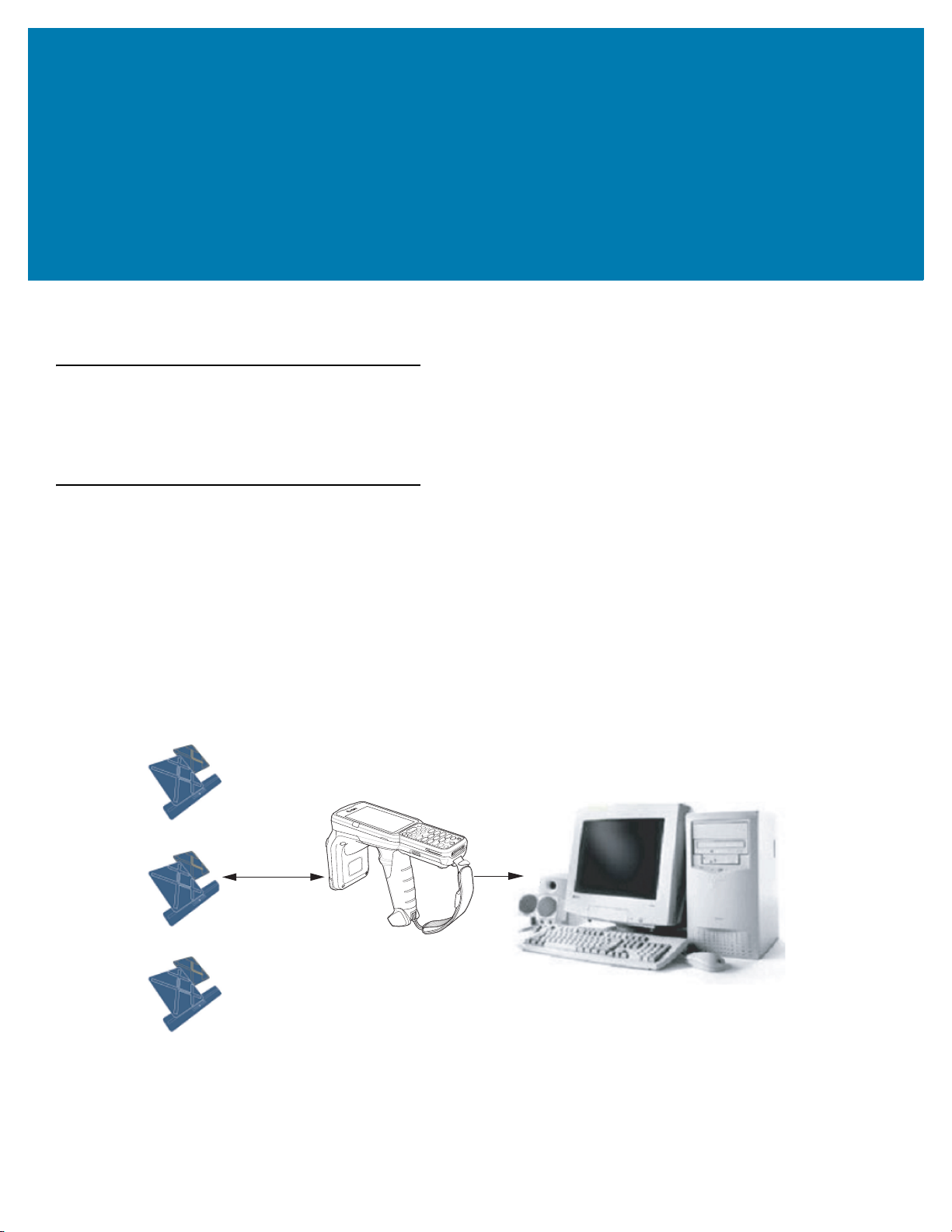
Host Computer
Tags
Mobile Computer
RF Wave and
Response
Wireless LAN/
BT/ActiveSync
Introduction
This chapter provides an overview of RFID technology and components, and describes the MC3300R RFID mobile
computer LED indications.
RFID Technology Overview
RFID (Radio Frequency Identification) is an advanced automatic identification (Auto ID) technology that uses radio
frequency signals to identify tagged items. An RFID tag contains a circuit that can store data. This data may be
pre-encoded or can be encoded in the field. The tags come in a variety of shapes and sizes.
To read a tag, the mobile computer sends out radio frequency waves using its integrated antenna. This RF field
powers and charges the tags, which are tuned to receive radio waves. The tags use this power to modulate the
carrier signal. The reader interprets the modulated signal and converts the data to a format for computer storage.
The computer application translates the data into an understandable format.
Figure 2 RFID System Elements
14
Page 15

Getting Started
RFID Components
Zebra RFID solutions offer low cost, long read range, and a high read rate. These features provide real time
end-to-end visibility of products and assets in the factory, distribution center, retail outlet, or other facility. The
MC3300R RFID system consists of the following components:
Silicon-based RFID tags that attach to retail products, vehicles, trailers, containers, pallets, boxes, etc.
An integrated antenna that supports applications such as item level tracking and asset tracking.
An embedded radio module that powers and communicates with tags for data capture and provides host
connectivity for data migration.
Tags
Tags contain embedded chips that store unique information. Available in various shapes and sizes, tags, often
called transponders, receive and respond to data requests. Tags require power to send data.
There are several categories of tags based on the protocol they support, read/write memory, and power options:
Active RFID tags are powered by internal light-weight batteries, and also use these batteries to broadcast radio
waves to the reader.
Semi-passive RFID tags are also powered by internal light-weight batteries, but draw broadcasting power from the
reader.
Passive RFID tags are powered by a reader-generated RF field. These tags are much lighter and less expensive
than active tags, and are typically applied to less expensive goods.
Antenna
Antennas transmit and receive radio frequency signals.
Radio Module
The radio module communicates with the tags and transfers the data to a host computer. It also provides features
such as filtering, CRC check, and tag writing. The MC3300R RFID mobile computer supports standard RFID tags
as described by EPCGlobalTM Class 1 Gen2 protocol.
LED Indications
The Charge LED Indicator indicates the charge status.
Table 2 LED Charge Indicators
Status Indications
Off The battery is not charging.
The battery is not inserted correctly in the cradle or connected to a power
source.
Cradle is not powered.
Green Fast (20 ms) Tag read and/or write.
15
Page 16

Status Indications
Green Slow (200 ms) Firmware update in progress.
Red (5 s); Green Slow (200 ms) Firmware recovery mode followed by firmware update.
Setting Up the MC3300R
To start using the MC3300R for the first time:
• Ensure the battery is installed
• Charge the MC3300R
• Power on the MC3300R
• Remove MC3300R from charger
• Set the region and power level (using the RFID Manager Application, Demo Application, or the partner
application).
Getting Started
16
Page 17
Accessories
Introduction
This chapter provides information on using the accessories for the device.
MC3300R Accessories
The table below lists the accessories available for the MC3300R.
Table 3 MC3300R Accessories
Accessory Part Number Description
Cradles
1-Slot USB Charge Cradle with Spare Battery
Charger
5-Slot Charge Only ShareCradle CRD-MC33-5SCHG-01 Charge only. Charges up to five
5-Slot Ethernet ShareCradle CRD-MC33-5SETH-01 Charges up to five MC3300Rs and
CRD-MC33-2SUCHG-01 Charges the MC3300R main battery
and a spare battery, and
synchronizes the MC3300R with a
host computer through a USB
connection. Requires power supply
(PWR-BGA12V50W0WW), DC line
cord (CBL-DC-388A1-01) and a
country specific grounded AC line
cord.
MC3300Rs. Requires power supply
(PWR-BGA12V108W0WW), DC line
cord (CBL-DC-381A1-01) and a
country specific grounded AC line
cord.
provides Ethernet communication for
up to five devices. Requires power
supply (PWR-BGA12V108W0WW),
DC line cord (CBL-DC-381A1-01)
and a country specific grounded AC
line cord.
17
Page 18

Table 3 MC3300R Accessories (Continued)
Accessory Part Number Description
Accessories
4-Slot Charge ShareCradle with 4-Slot Battery
Charger
4-Slot Ethernet ShareCradle with 4-Slot
Battery Charger
Chargers
4-Slot Spare Battery Charger SAC-MC33-4SCHG-01 Charges up to four MC3300R spare
CRD-MC33-4SC4BC-01 Charge only. Charges up to four
MC3300Rs and up to four spare
batteries. Requires power supply
(PWR-BGA12V108W0WW), DC line
cord (CBL-DC-381A1-01) and a
country specific grounded AC line
cord.
CRD-MC33-4SE4BC-01 Charges up to four MC3300Rs and
up to four spare batteries and
provides Ethernet communication for
up to four MC3300Rs. Requires
power supply
(PWR-BGA12V108W0WW), DC line
cord (CBL-DC-381A1-01) and a
country specific grounded AC line
cord.
batteries. Requires power supply
(PWR-BGA12V50W0WW), DC line
cord (CBL-DC-388A1-01) and a
country specific grounded AC line
cord.
20-Slot Spare Battery Charger SAC-MC33-20SCHG-01 Charges up to 20 MC3300R spare
batteries. Requires power supply
(PWR-BGA12V108W0WW), DC line
cord (CBL-DC-381A1-01) and a
country specific grounded AC line
cord.
Power Supply PWR-BGA12V50W0WW
Power Supply
PWR-BGA12V108W0W
W
Level VI power supply. Provides 12
VDC, 2.5A power to the 1-Slot USB
Charge Cradle and the 4-Slot Spare
Battery Charger. Requires a DC line
cord (CBL-DC-388A1-01) and a
country specific grounded AC line
cord.
Level VI power supply. Provides 12
VDC, 2.5A power to the 5-Slot
Charge Only Cradle, 5-Slot Ethernet
Cradle, 5-Slot Charge Cradle with
4-Slot Battery Charger, 5-Slot
Ethernet Cradle with 4-Slot Battery
Charger and 20-Slot Battery
Charger. Requires a DC line cord
(CBL-DC-381A1-01) and a country
specific grounded AC line cord.
18
Page 19

Table 3 MC3300R Accessories (Continued)
Accessory Part Number Description
Accessories
Power Supply
Power Supply PWR-WUA5V12W0GB Provides 12 VDC, 2.5A power to the
Power Supply PWR-WUA5V12W0EU Provides 12 VDC, 2.5A power to the
Power Supply PWR-WUA5V12W0AU Provides 12 VDC, 2.5A power to the
Power Supply PWR-WUA5V12W0CN Provides 12 VDC, 2.5A power to the
Power Supply PWR-WUA5V12W0IN Provides 12 VDC, 2.5A power to the
PWR-WUA5V12W0US
Wall adapter; Provides 12 VDC, 2.5A
power to the USB Charge Cable.
Includes plug adapter for use in the
United States.
USB Charge Cable. Includes plug
adapter for use in the European
Union.
USB Charge Cable. Includes plug
adapter for use in the United
Kingdom.
USB Charge Cable. Includes plug
adapter for use in Australia.
USB Charge Cable. Includes plug
adapter for use in China.
USB Charge Cable. Includes plug
adapter for use in India.
US AC Line Cord 23844-00-00R Provides power to 3–wire power
supplies PWR-BGA12V50W0WW
and PWR-BGA12V108W0WW.
DC Line Cord CBL-DC-381A1-01 Provides power from the power
supply (PWR-BGA12V108W0WW)
to the 5-Slot Charge Only Cradle,
5-Slot Ethernet Cradle, 5-Slot
Charge Cradle with 4-Slot Battery
Charger, 5-Slot Ethernet Cradle with
4-Slot Battery Charger and 20-Slot
Battery Charger.
DC Line Cord CBL-DC-388A1-01 Provides power from the power
supply (PWR-BGA12V150W0WW)
to the 1-Slot USB Charge Cradle and
4-Slot Battery Charger.
Cables
USB Charge Cable CBL-MC33-USBCHG-01 Provides power and/or
communication over USB to the
device. Requires wall adapter/power
supply PWR-WUA5V12W0xx.
1-Slot Cradle USB Cable 25-124330-01R Provides USB communication
through the 1-Slot USB cradle to the
host computer.
19
Page 20
Accessories
Table 3 MC3300R Accessories (Continued)
Accessory Part Number Description
Miscellaneous
Cradle Adapter ADP-MC33-CRDCUP-01 MC3300R Charge Only Adapter for
backwards compatibility with MC32
cradles. Works with MC32N0 1-Slot
USB Cradle, 4-Slot Charge Only
Cradle, and 4-Slot Ethernet Cradles.
5200 mAh Battery (Extended
PowerPrecision+)
Hand Strap SG-MC33-HDSTPG-01 Replacement hand strap for the
Fabric Holster SG-MC3021212–01R Provides a soft, clip on holster and a
Shoulder Strap 58-40000-007R Universal shoulder strap.
Belt 11-08062-02R Belt for fabric holster.
Rubber Boot SG-MC33-RBTG-02
Tempered Glass Screen Protector MISC-MC33-SCRN-01 Provides additional protection for
Stylus and Tether SG-TC7X-STYLUS-03 Conductive carbon-filled stylus for
BTRY-MC33-52MA-01
BTRY-MC33-52MA-10
BTRY-MC33-52MA-IN
SG-MC33-RBTG-03
Replacement extended capacity
battery.
Replacement extended capacity
battery (10–pack).
Replacement extended capacity
battery (India).
MC3300R. Hand strap loop holds an
optional stylus
(SG-TC7X-STYLUS-03).
shoulder strap for the MC3300R.
Provides additional protection for
wear and tear of the MC3300R.
display (5-pack).
capacitive touch panel; includes
coiled tether (3-pack).
20
Page 21
Compatibility
The table below displays compatibility between MC3300R devices and MC32N0 mobile computers and
accessories.
Table 4 Compatibility
Accessories
MC3300R
PP+
Batteries
MC3300R mobile computer Yes Yes Yes Yes
MC32N0 mobile computer No Yes No Yes N/A N/A
MC3300R PP+ Battery N/A N/A Yes No Yes No
MC32N0 PP Battery N/A N/A Yes Yes Yes Yes
MC32N0
PP
Batteries
MC3300R
Cradles
MC32N0
Cradles
w/adapter
MC3300R
Battery
Charger
N/A N/A
• MC3300R mobile computers are compatible with all batteries (MC3300R PowerPrecision+ and MC32N0
PowerPrecision).
• MC3300R mobile computer is compatible with all cradles.
An additional adapter is needed to use any MC32N0 cradle slot, which provides charge only, no
communication.
• MC3300R battery charger slots are compatible with all batteries (MC3300R PowerPrecision+ and
MC32N0 PowerPrecision).
• MC32N0 mobile computers are not compatible with MC3300R cradles.
Battery Comparison
MC32N0
Battery
Charger
The table below displays a comparison of the MC3300R batteries with the MC32N0 batteries.
Table 5 Battery Comparison
Feature MC32N0 MC3300R
Battery Type PowerPrecision PowerPrecision+
Includes Zebra and PowerPrecision+ recessed logos No Yes
Back Label Grey Blue
Battery Compatibility
• MC3300R PowerPrecision+ batteries are compatible with all MC3300R mobile computers and
accessories.
• MC3300R PowerPrecision+ batteries are not compatible with MC32N0 mobile computers and
accessories.
• MC32N0 PowerPrecision batteries are compatible with all MC32N0 mobile computers and accessories.
• MC32N0 PowerPrecision batteries are compatible with all MC3300R mobile computers and accessories.
21
Page 22
1-Slot USB Charge Cradle
AC Line Cord
Power Supply
DC Line Cord
USB Cable
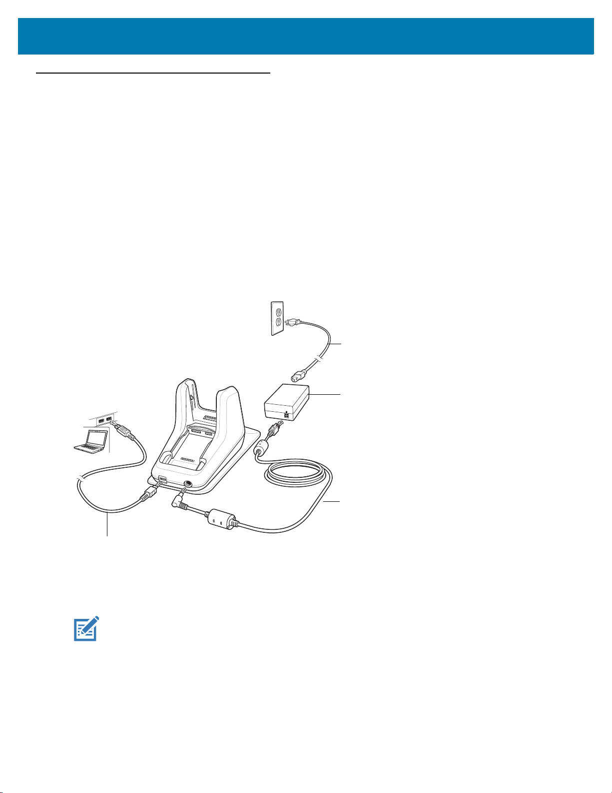
The 1-Slot USB Charge Cradle:
• Provides 9 VDC power for charging the mobile computer and charging the battery.
• Provides 4.2 VDC power to charge the spare battery.
• Provides a USB port for data communication between the mobile computer and a host computer or other
USB devices (e.g., a printer).
• Synchronizes information between the mobile computer and a host computer. With customized or third
party software, it can also synchronize the mobile computer with corporate databases.
• Compatible with the following batteries:
• MC3300R 5200 mAh PowerPrecision+ extended battery.
• MC32N0 5200 mAh PowerPrecision extended battery.
Figure 3 1-Slot USB Charge Cradle Setup
Accessories
Charging the MC3300R Battery
NOTE: To function properly, remove the lower part of the rubber boot or the entire rubber boot before placing in
a charging cradle.
1. Ensure that the cradle is connected to power.
2. Slide the mobile computer into the slot in the cradle. The mobile computer Charge LED Indicator, indicates the
mobile computer battery charging status. For charging status, see Table 6 on page 24
22
Page 23
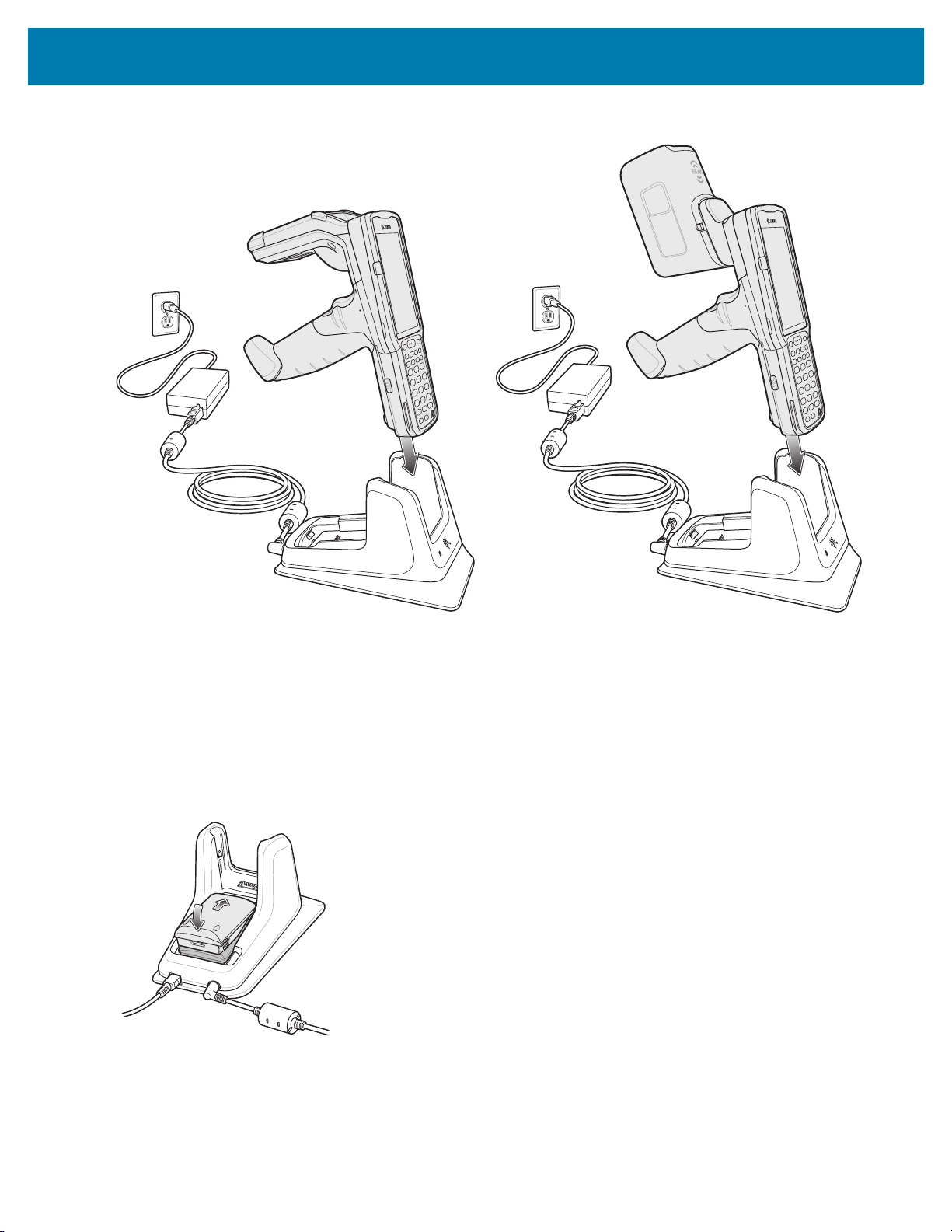
Figure 4 MC3300R Battery Charging
Accessories
3. Gently press down on the device to ensure proper contact.
4. When charging is complete, remove the mobile computer from the cradle slot.
Charging an MC3300R Spare Battery
1. Ensure that the cradle is connected to power.
2. Insert the spare battery into the cradle, bottom first, and pivot the top of the battery down onto the contact pins.
Figure 5 MC3300R Spare Battery Charging
3. Gently press down on the battery to ensure proper contact.
The Spare Battery Charging LED on the front of the cradle indicates the spare battery charging status.
4. When charging is complete, lift the battery out of the slot.
23
Page 24
Accessories
Battery Charging in 1- Slot USB Charge Cradle
The 1-Slot USB charge cradle charges the MC3300R’s main battery and a spare battery simultaneously.
The MC3300R’s Charge LED indicates the status of the battery charging in the MC3300R. See Table 6 for
charging status indications.
The spare battery charging LED on the cradle indicates the status of the spare battery charging in the cradle. See
below for charging status indications.
Table 6 Spare Battery LED Charging Indicators
Spare Battery LED (on cradle) Indication
Off • The battery is not charging.
• The battery is not inserted correctly in the cradle or
connected to a power source.
• Cradle is not powered.
Solid Amber • Battery is charging.
Solid Green • Battery charging is complete.
Fast Blinking Red
2 blinks/second
Solid Red • Spare battery is charging and battery is at the end
The MC3300R 5200 mAh PowerPrecision+ extended battery charges from 0% to 90% in less than 3.8 hours at
room temperature.
The MC32N0 5200 mAh PowerPrecision extended battery charges from 0% to 90% in less than 5.5 hours at room
temperature.
Charging error, e.g.:
• Temperature is too low or too high.
• Charging has gone on too long without completion
(typically eight hours).
of useful life.
• Charging complete and battery is at the end of
useful life.
Charging Temperature
Charge batteries in temperatures from 0 °C to 40 °C (32 °F to 104 °F). Charging is intelligently controlled by the
MC3300R.
To accomplish this, for small periods of time, the MC3300R or cradle alternately enables and disables battery
charging to keep the battery at acceptable temperatures. The MC3300R or cradle indicates when charging is
disabled due to abnormal temperatures via its LED.
24
Page 25
5-Slot Charge Only ShareCradle
AC Line Cord
DC Line Cord
Power Supply
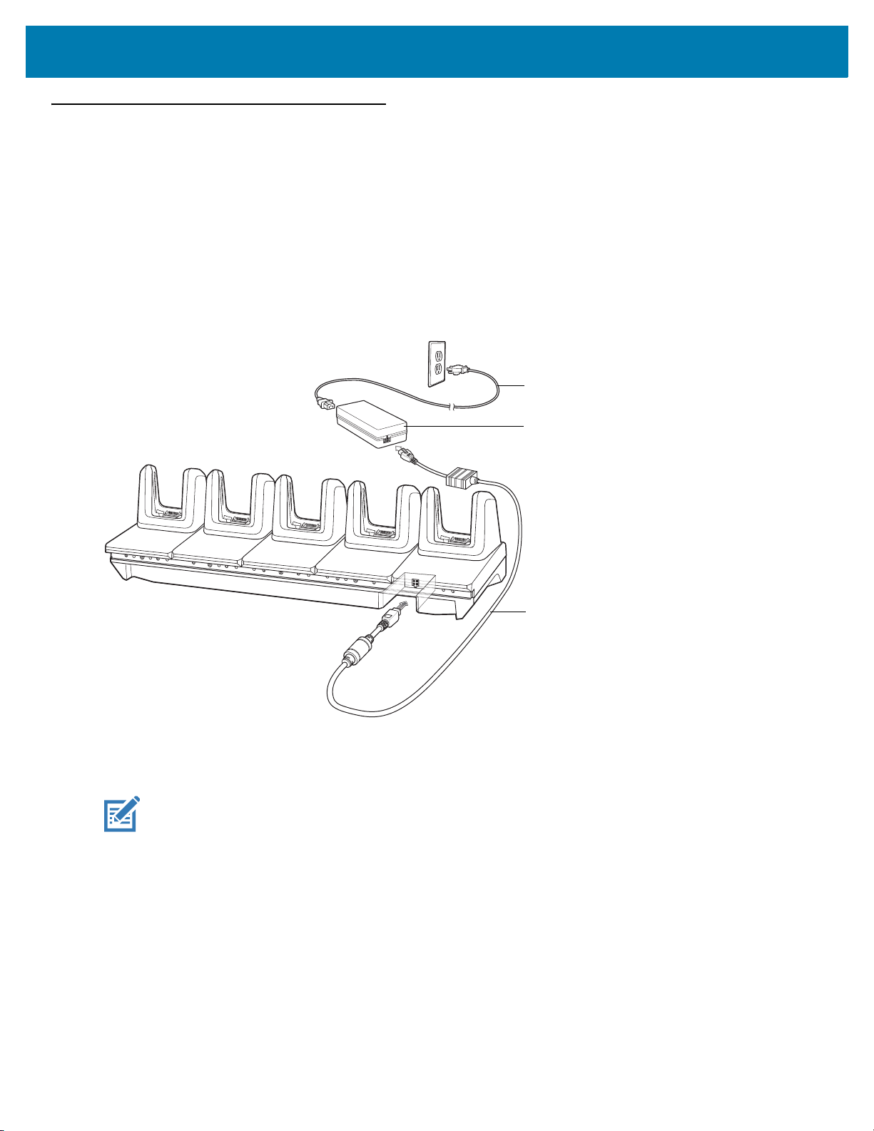
The 5-Slot Charge Only ShareCradle:
• Provides 9 VDC power for operating the mobile computer and charging the battery.
• Simultaneously charges up to five mobile computers.
• Compatible with devices using the following batteries:
• MC3300R 5200 mAh PowerPrecision+ extended battery.
• MC32N0 5200 mAh PowerPrecision extended battery.
Figure 6 5-Slot Charge Only ShareCradle Setup
Accessories
Charging the MC3300R Battery
NOTE: To function properly, remove the lower part of the rubber boot or the entire rubber boot before placing in
a charging cradle.
1. Ensure that the cradle is connected to power.
2. Slide the mobile computer into the slot in the cradle. The mobile computer Charge LED Indicator, indicates the
mobile computer battery charging status.
3. Gently press down on the device to ensure proper contact.
4. When charging is complete, remove the mobile computer from the cradle slot.
Battery Charging in the 5-Slot Charge Only ShareCradle
The MC3300R’s Charge LED indicates the status of the battery charging in the MC3300R. See Table 10 on page
43 for charging status indications.
25
Page 26

Accessories
The MC3300R 5200 mAh PowerPrecision+ extended battery charges from 0% to 90% in less than 3.8 hours at
room temperature.
The MC32N0 5200 mAh PowerPrecision extended battery charges from 0% to 90% in less than 5.5 hours at room
temperature.
Charging Temperature
Charge batteries in temperatures from 0 °C to 40 °C (32 °F to 104 °F). Charging is intelligently controlled by the
MC3300R.
To accomplish this, for small periods of time, the MC3300R or cradle alternately enables and disables battery
charging to keep the battery at acceptable temperatures. The MC3300R or cradle indicates when charging is
disabled due to abnormal temperatures via its LED.
26
Page 27
5-Slot Ethernet ShareCradle
AC Line Cord
DC Line Cord
Power Supply
Primary PortEthernet Cable
Router
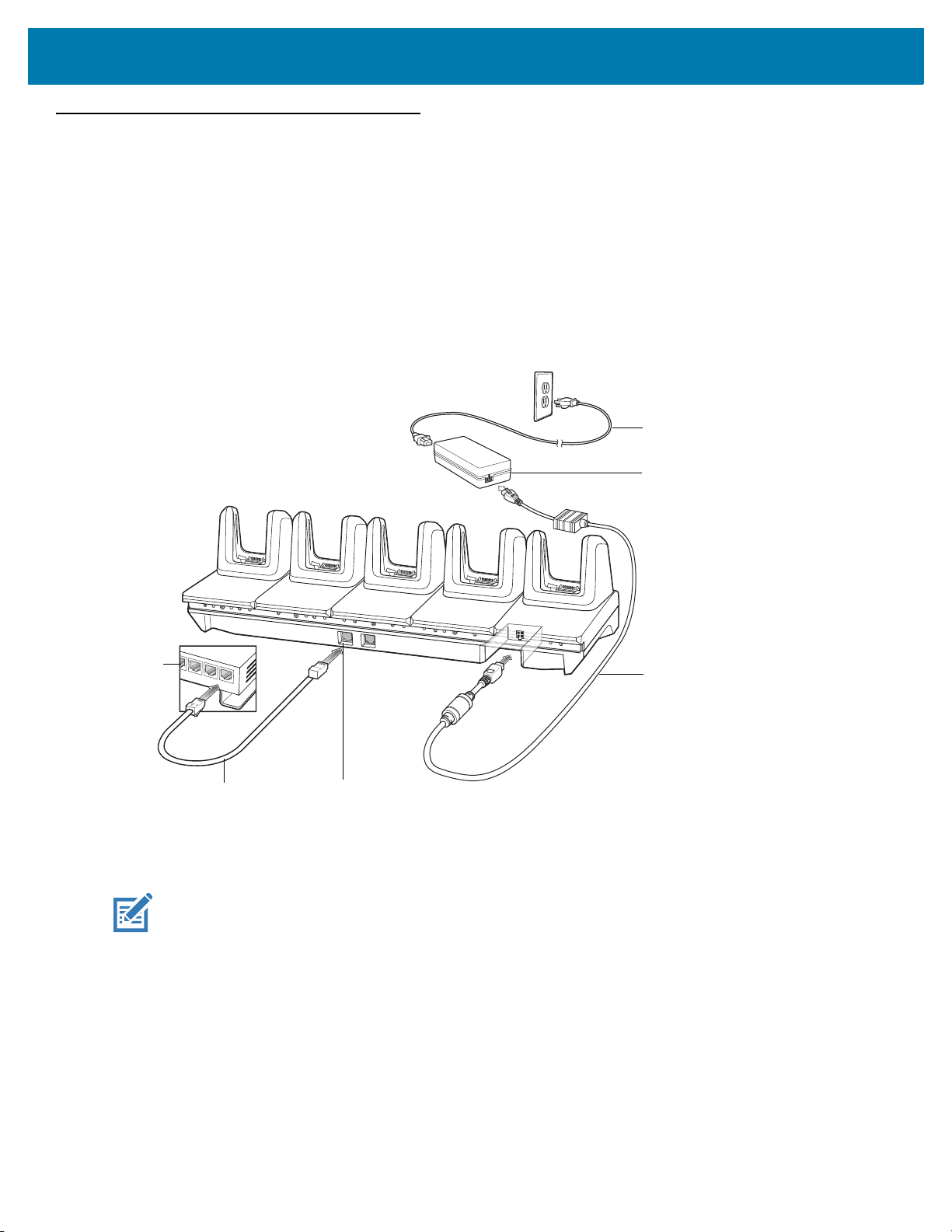
The 5-Slot Ethernet ShareCradle:
• Provides 9 VDC power for operating the mobile computer and charging the battery.
• Simultaneously charges up to five mobile computers.
• Compatible with devices using the following batteries:
• MC3300R 5200 mAh PowerPrecision+ extended battery.
• MC32N0 5200 mAh PowerPrecision extended battery.
Figure 7 5-Slot Ethernet ShareCradle Setup
Accessories
Charging the MC3300R Battery
NOTE: To function properly, remove the lower part of the rubber boot or the entire rubber boot before placing in
a charging cradle.
1. Ensure that the cradle is connected to power.
2. Slide the mobile computer into the slot in the cradle. The mobile computer amber Charge LED Indicator,
indicates the mobile computer battery charging status.
3. Gently press down on the device to ensure proper contact.
4. When charging is complete, remove the mobile computer from the cradle slot.
27
Page 28

Accessories
Battery Charging in the 5-Slot Ethernet ShareCradle
The MC3300R’s Charge LED indicates the status of the battery charging in the MC3300R. See Table 10 on page
43 for charging status indications.
The MC3300R 5200 mAh PowerPrecision+ extended battery charges from 0% to 90% in less than 3.8 hours at
room temperature.
The MC32N0 5200 mAh PowerPrecision extended battery charges from 0% to 90% in less than 5.5 hours at room
temperature.
Charging Temperature
Charge batteries in temperatures from 0 °C to 40 °C (32 °F to 104 °F). Charging is intelligently controlled by the
MC3300R.
To accomplish this, for small periods of time, the MC3300R or cradle alternately enables and disables battery
charging to keep the battery at acceptable temperatures. The MC3300R or cradle indicates when charging is
disabled due to abnormal temperatures via its LED.
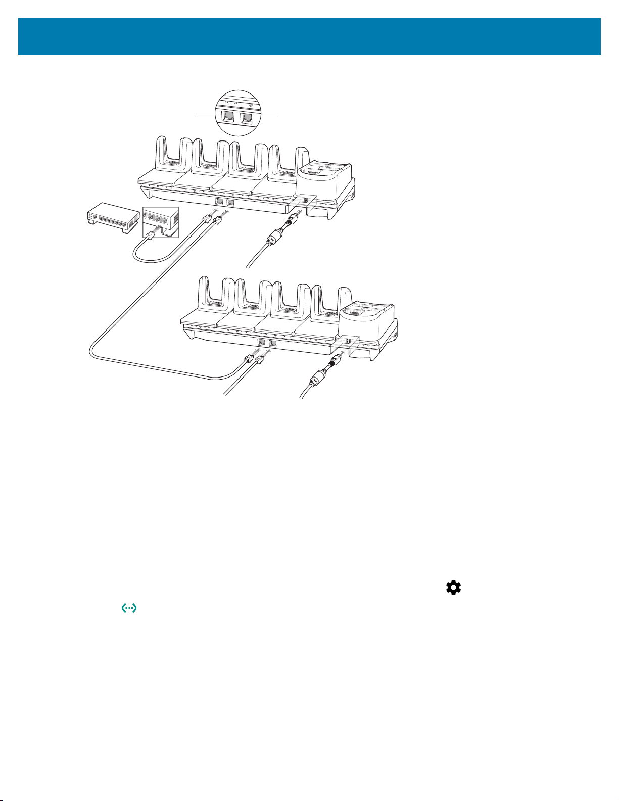
Daisy-chaining Ethernet ShareCradles
Daisy-chain up to ten 5-Slot Ethernet ShareCradles to connect several cradles to an Ethernet network. Use either
a straight or crossover cable. Daisy-chaining should not be attempted when the main Ethernet connection to the
first cradle is 10 Mbps or throughput issues are likely to occur.
To daisy-chain 5-Slot Ethernet ShareCradles:
1. Connect power to each 5-Slot Ethernet ShareCradle.
2. Connect an Ethernet cable to one of the ports on the switch and the other end to the Primary Port of the first
cradle.
3. Connect an Ethernet cable to the Secondary port of the first cradle.
4. Connect the other end of the Ethernet cable to the Primary port of the next 5-Slot Ethernet ShareCradle.
28
Page 29

Accessories
To Power Supply
To Next Cradle
To Power Supply
To Switch
Secondary Port
Primary Port
Figure 8 Daisy-chaining 5-Slot Ethernet ShareCradles
5. Connect additional cradles as described in step 3 and 4.
Ethernet Settings
The following settings can be configured when using Ethernet communication:
• Proxy Settings
• Static IP.
Configuring Ethernet Proxy Settings
The MC3300R includes Ethernet cradle drivers. After inserting the MC3300R, configure the Ethernet connection:
1. Swipe down from the status bar to open the quick access panel and then touch .
2. Touch Ethernet.
3. Slide the switch to the ON position.
4. Place the MC3300R into the Ethernet cradle slot.
5. Touch and hold eth0 until the menu appears.
6. Touch Modify Proxy.
7. Touch the Proxy drop-down list and select Manual.
29
Page 30

Accessories
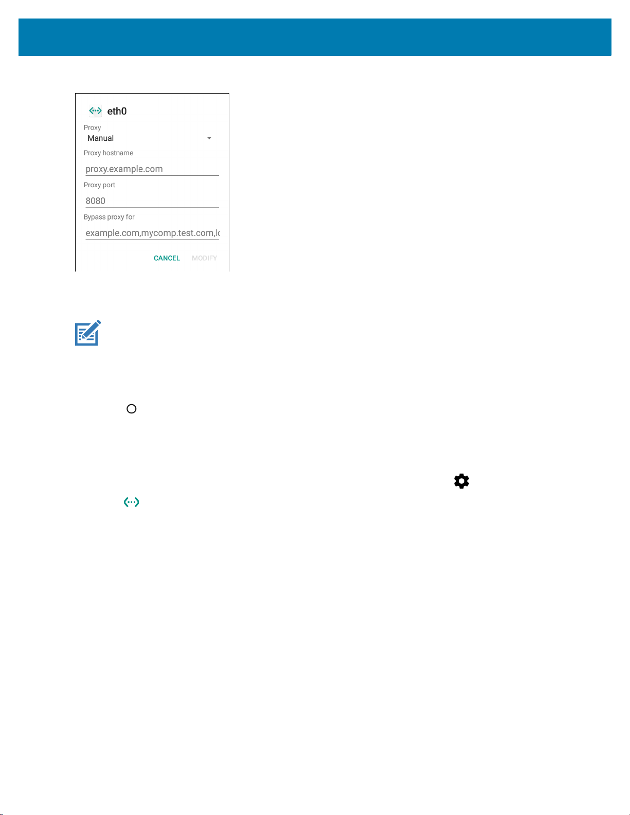
Figure 9 Ethernet Proxy Settings
8. In the Proxy hostname field, enter the proxy server address.
9. In the Proxy port field, enter the proxy server port number.
NOTE: When entering proxy addresses in the Bypass proxy for field, do not use spaces or carriage returns
between addresses.
10. In the Bypass proxy for text box, enter addresses for web sites that do not require to go through the proxy
server. Use the separator “|” between addresses.
11. Touch MODIFY.
12. Touch .
Configuring Ethernet Static IP Address
The MC3300R includes Ethernet cradle drivers. After inserting the MC3300R, configure the Ethernet connection:
1. Swipe down from the status bar to open the quick access panel and then touch .
2. Touch Ethernet.
3. Slide the switch to the ON position.
4. Place the MC3300R into the Ethernet cradle slot.
5. Touch eth0.
6. Touch Disconnect.
7. Touch eth0.
8. Touch the IP settings drop-down list and select Static.
30
Page 31

Figure 10 Static IP Settings
Accessories
9. In the IP address field, enter the proxy server address.
10. If required, in the Gateway field, enter a gateway address for the device.
11. If required, in the Netmask field, enter the network mask address
12. If required, in the DNS address fields, enter a Domain Name System (DNS) addresses.
13. Touch CONNECT.
14. Touch .
Establishing Ethernet Connection
1. Swipe down from the status bar to open the quick access panel and then touch .
2. Touch Ethernet.
3. Slide the Ethernet switch to the ON position.
4. Insert the device into a slot.
The icon appears in the Status bar.
5. Touch eth0 to view Ethernet connection details.
31
Page 32

Accessories
LED Indicators
There are two green LEDs on the side of the cradle. These green LEDs light and blink to indicate the data transfer
rate.
Table 7 LED Data Rate Indicators
Data Rate 1000 LED 100/10 LED
1 Gbps On/Blink Off
100 Mbps Off On/Blink
10 Mbps Off On/Blink
32
Page 33

Accessories
AC Line Cord
DC Line Cord
Power Supply
4-Slot ShareCradle with 4-Slot Battery Charger
The 4-Slot ShareCradle with 4-Slot Battery Charger:
• Provides 9 VDC power for operating the mobile computer and charging the battery.
• Provides 4.2 VDC power for charging spare batteries.
• Simultaneously charges up to four mobile computers and four spare batteries.
• Compatible with the following batteries:
• MC3300R 5200 mAh PowerPrecision+ extended battery.
• MC32N0 5200 mAh PowerPrecision extended battery.
Figure 11 4-Slot ShareCradle with 4-Slot Battery Charger Setup
Charging the MC3300R Battery
NOTE: To function properly, remove the lower part of the rubber boot or the entire rubber boot before placing in
a charging cradle.
1. Ensure that the cradle is connected to power.
2. Slide the mobile computer into the slot in the cradle. The mobile computer amber Charge LED Indicator,
indicates the mobile computer battery charging status.
3. Gently press down on the device to ensure proper contact.
4. When charging is complete, remove the mobile computer from the cradle slot.
33
Page 34

Accessories
Charging Spare Batteries
Insert the battery into the charger and gently press down on the battery to ensure proper contact.
Battery Charging in the 4-Slot ShareCradle with 4-Slot Battery Charger
The MC3300R’s Charge LED or the spare battery LED indicates the status of the battery charging in the
MC3300R. See Table 9 on page 41 for charging status indications.
The MC3300R 5200 mAh PowerPrecision+ extended battery charges from 0% to 90% in less than 3.8 hours at
room temperature.
The MC32N0 5200 mAh PowerPrecision extended battery charges from 0% to 90% in less than 5.5 hours at room
temperature.
Charging Temperature
Charge batteries in temperatures from 0 °C to 40 °C (32 °F to 104 °F). Charging is intelligently controlled by the
MC3300R.
To accomplish this, for small periods of time, the MC3300R or cradle alternately enables and disables battery
charging to keep the battery at acceptable temperatures. The MC3300R or cradle indicates when charging is
disabled due to abnormal temperatures via its LED.
34
Page 35

Accessories
AC Line Cord
DC Line Cord
Power Supply
Primary Port
Ethernet Cable
Router
4-Slot Ethernet ShareCradle with 4-Slot Battery Charger
The 4-Slot Ethernet ShareCradle with 4-Slot Battery Charger:
• Provides 9 VDC power for operating the mobile computer and charging the battery.
• Provides 4.2 VDC power for charging spare batteries.
• Simultaneously charges up to four mobile computers and four spare batteries.
• Compatible with the following batteries:
• MC3300R 5200 mAh PowerPrecision+ extended battery.
• MC32N0 5200 mAh PowerPrecision extended battery.
Figure 12 4-Slot Ethernet ShareCradle with 4-Slot Battery Charger Setup
Charging the MC3300R Battery
NOTE: To function properly, remove the lower part of the rubber boot or the entire rubber boot before placing in
a charging cradle.
1. Ensure that the cradle is connected to power.
2. Slide the mobile computer into the slot in the cradle. The mobile computer amber Charge LED Indicator,
indicates the mobile computer battery charging status.
3. Gently press down on the device to ensure proper contact.
4. When charging is complete, remove the mobile computer from the cradle slot.
35
Page 36

Accessories
Charging Spare Batteries
Insert the battery into the charger and gently press down on the battery to ensure proper contact.
Battery Charging in the 4-Slot Ethernet ShareCradle with 4-Slot Battery Charger
The MC3300R’s Charge LED or the spare battery LED indicates the status of the battery charging in the
MC3300R. See Table 9 on page 41 for charging status indications.
The MC3300R 5200 mAh PowerPrecision+ extended battery charges from 0% to 90% in less than 3.8 hours at
room temperature.
The MC32N0 5200 mAh PowerPrecision extended battery charges from 0% to 90% in less than 5.5 hours at room
temperature.
Charging Temperature
Charge batteries in temperatures from 0 °C to 40 °C (32 °F to 104 °F). Charging is intelligently controlled by the
MC3300R.
To accomplish this, for small periods of time, the MC3300R or cradle alternately enables and disables battery
charging to keep the battery at acceptable temperatures. The MC3300R or cradle indicates when charging is
disabled due to abnormal temperatures via its LED.
Daisy-chaining Ethernet Cradles
Daisy-chain up to ten 5-Slot Ethernet ShareCradle with 4-Slot Battery Chargers to connect several cradles to an
Ethernet network. Use either a straight or crossover cable. Daisy-chaining should not be attempted when the main
Ethernet connection to the first cradle is 10 Mbps as throughput issues are likely to occur.
To daisy-chain 5-Slot Ethernet ShareCradle with 4-Slot Battery Chargers:
1. Connect power to each 5-Slot Ethernet ShareCradle with 4-Slot Battery Charger.
2. Connect an Ethernet cable to one of the ports on the switch and the other end to the Primary Port of the first
cradle.
3. Connect an Ethernet cable to the Secondary port of the first cradle.
4. Connect the other end of the Ethernet cable to the Primary port of the next 5-Slot Ethernet ShareCradle with
4-Slot Battery Charger.
36
Page 37
Accessories
To Power Supply
To Next Cradle
To Power Supply
To Switch
Secondary Port
Primary Port
Figure 13 Daisy-chaining 5-Slot Ethernet ShareCradle with 4-Slot Battery Chargers
5. Connect additional cradles as described in step 3 and 4.
Ethernet Settings
The following settings can be configured when using Ethernet communication:
• Proxy Settings
• Static IP.
Configuring Ethernet Proxy Settings
The MC3300R includes Ethernet cradle drivers. After inserting the MC3300R, configure the Ethernet connection:
1. Swipe down from the status bar to open the quick access panel and then touch .
2. Touch Ethernet.
3. Slide the switch to the ON position.
4. Place the MC3300R into the Ethernet cradle slot.
5. Touch and hold eth0 until the menu appears.
6. Touch Modify Proxy.
7. Touch the Proxy drop-down list and select Manual.
37
Page 38
Accessories
Figure 14 Ethernet Proxy Settings
8. In the Proxy hostname field, enter the proxy server address.
9. In the Proxy port field, enter the proxy server port number.
NOTE: When entering proxy addresses in the Bypass proxy for field, do not use spaces or carriage returns
between addresses.
10. In the Bypass proxy for text box, enter addresses for web sites that do not require to go through the proxy
server. Use the separator “|” between addresses.
11. Touch MODIFY.
12. Touch .
Configuring Ethernet Static IP Address
The MC3300R includes Ethernet cradle drivers. After inserting the MC3300R, configure the Ethernet connection:
1. Swipe down from the status bar to open the quick access panel and then touch .
2. Touch Ethernet.
3. Slide the switch to the ON position.
4. Place the MC3300R into the Ethernet cradle slot.
5. Touch eth0.
6. Touch Disconnect.
7. Touch eth0.
8. Touch the IP settings drop-down list and select Static.
38
Page 39

Figure 15 Static IP Settings
Accessories
9. In the IP address field, enter the proxy server address.
10. If required, in the Gateway field, enter a gateway address for the device.
11. If required, in the Netmask field, enter the network mask address
12. If required, in the DNS address fields, enter a Domain Name System (DNS) addresses.
13. Touch CONNECT.
14. Touch .
Establishing Ethernet Connection
1. Swipe down from the status bar to open the quick access panel and then touch .
2. Touch Ethernet.
3. Slide the Ethernet switch to the ON position.
4. Insert the device into a slot.
The icon appears in the Status bar.
5. Touch eth0 to view Ethernet connection details.
39
Page 40

LED Indicators
There are two green LEDs on the side of the cradle. These green LEDs light and blink to indicate the data transfer
rate.
Table 8 LED Data Rate Indicators
Data Rate 1000 LED 100/10 LED
1 Gbps On/Blink Off
100 Mbps Off On/Blink
10 Mbps Off On/Blink
4-Slot Spare Battery Charger
The 4-Slot Battery Charger:
• Charges up to four MC3300R spare batteries.
• Provides 4.2 VDC power to charge the spare battery.
• Compatible with the following batteries:
Accessories
• MC3300R 5200 mAh PowerPrecision+ extended battery.
• MC32N0 5200 mAh PowerPrecision extended battery.
Charging Spare Batteries
1. Connect the charger to a power source.
2. Insert the battery into the charger and gently press down on the battery to ensure proper contact.
40
Page 41

Figure 16 4-Slot Battery Charger Setup
AC Line Cord
DC Line Cord
Power Supply
Accessories
Battery Charging
Spare Battery Charging
Each Battery Charging LED indicates the status of the battery charging in each slot. The table below describes the
Battery Charging LED status.
Table 9 Battery LED Charging Indicators
LED Indication
Off • The battery is not charging.
• The battery is not inserted correctly in the cradle or
connected to a power source.
• Cradle is not powered.
Solid Amber • Battery is charging.
Solid Green • Battery charging is complete.
Fast Blinking Red
2 blinks/second
Charging error, e.g.:
• Temperature is too low or too high.
• Charging has gone on too long without completion
(typically eight hours).
Solid Red • Spare battery is charging and battery is at the end
of useful life.
• Charging complete and battery is at the end of
useful life.
41
Page 42

The MC3300R 5200 mAh PowerPrecision+ extended battery charges from 0% to 90% in less than 3.8 hours at
AC Line Cord
DC Line Cord
Power Supply
room temperature.
The MC32N0 5200 mAh PowerPrecision extended battery charges from 0% to 90% in less than 5.5 hours at room
temperature.
Charging Temperature
Charge batteries in temperatures from 0 °C to 40 °C (32 °F to 104 °F). Charging is intelligently controlled by the
MC3300R.
To accomplish this, for small periods of time, the changer alternately enables and disables battery charging to keep
the battery at acceptable temperatures. The charger indicates when charging is disabled due to abnormal
temperatures via its LED.
20-Slot Spare Battery Charger
The 20-Slot Battery Charger:
• Charges up to twenty MC3300R spare batteries.
• Provides 4.2 VDC power to charge the spare battery.
• Compatible with the following batteries:
• MC3300R 5200 mAh PowerPrecision+ extended battery.
• MC32N0 5200 mAh PowerPrecision extended battery.
Accessories
Charging Spare Batteries
1. Connect the charger to a power source.
2. Insert the battery into the charger and gently press down on the battery to ensure proper contact.
Figure 17 20-Slot Battery Charger Setup
42
Page 43

Accessories
Battery Charging
Spare Battery Charging
Each Battery Charging LED indicates the status of the battery charging in each slot. The table below describes the
Battery Charging LED status.
Table 10 20-Slot Battery LED Charging Indicators
LED Indication
Off • The battery is not charging.
• The battery is not inserted correctly in the cradle or
connected to a power source.
• Cradle is not powered.
Solid Amber • Battery is charging.
Solid Green • Battery charging is complete.
Fast Blinking Red
2 blinks/second
Solid Red • Spare battery is charging and battery is at the end
The MC3300R 5200 mAh PowerPrecision+ extended battery charges from 0% to 90% in less than 5.5 hours at
room temperature.
The MC32N0 5200 mAh PowerPrecision extended battery charges from 0% to 90% in less than 5.5 hours at room
temperature.
Charging error, e.g.:
• Temperature is too low or too high.
• Charging has gone on too long without completion
(typically eight hours).
of useful life.
• Charging complete and battery is at the end of
useful life.
Charging Temperature
Charge batteries in temperatures from 0 °C to 40 °C (32 °F to 104 °F). Charging is intelligently controlled by the
MC3300R.
To accomplish this, for small periods of time, the changer alternately enables and disables battery charging to keep
the battery at acceptable temperatures. The charger indicates when charging is disabled due to abnormal
temperatures via its LED.
43
Page 44

USB Charge Cable
The USB Charge Cable:
• Provides 5 VDC power to charge the battery.
• Provides power and/or communication with the host computer over USB to the device.
• Compatible with devices using the following batteries:
• MC3300R 5200 mAh PowerPrecision+ extended battery.
• MC32N0 5200 mAh PowerPrecision extended battery.
The USB Charge Cable snaps onto the bottom of the MC3300R and removes easily when not in use. When
attached to the MC3300R allows charging only.
Figure 18 USB Charge Cable
Accessories
Connecting the USB Charge Cable to Device
NOTE: To function properly, remove the lower part of the rubber boot or the entire rubber boot before placing in
a charging cradle.
To connect the USB Charge Cable to the device, insert the USB Charge Cable straight onto the device until the
device touches the bottom of the cable cup.
44
Page 45

Accessories
Figure 19 Connecting the USB Charge Cable
Connecting the USB Charge Cable to Host Computer
To connect the USB Charge Cable to a host computer:
1. Connect the USB Charge Cable to the MC3300R.
2. Connect the USB connector of the cable to a host computer.
Figure 20 Connecting USB Charge Cable to Host Computer
45
Page 46

Accessories
Main Battery Charging
The device’s Charging/Notification LED indicates the status of the battery charging in the device.
NOTE: Charging using a host computer USB port could take longer.
To achieve the best charging results use only Zebra charging accessories and batteries. Charge
batteries at room temperature with the in sleep mode.
Charging the Device
To charge the device using the USB Charge Cable:
1. Connect the USB Charge Cable to the MC3300R.
2. Connect the USB connector of the power supply.
3. Plug the power supply into a power outlet.
Figure 21 Charging the Device
Main Battery Charging
The device’s Charging/Notification LED indicates the status of the battery charging in the device.
NOTE: In many cases the 90% charge provides plenty of charge for daily use.
To achieve the best charging results use only Zebra charging accessories and batteries. Charge
batteries at room temperature with the MC3300R in sleep mode.
The MC3300R 5200 mAh PowerPrecision+ extended battery charges from 0% to 90% in less than 6 hours at room
temperature.
The MC32N0 5200 mAh PowerPrecision extended battery charges from 0% to 90% in less than 6 hours at room
temperature.
46
Page 47

Accessories
Disconnecting the USB Charge Cable
To disconnect the USB Charge Cable from the MC3300R:
1. Grasp the cable cup in one hand (by pinching the front and back) and the device in the other hand.
2. Remove the device by pulling straight up.
Figure 22 Disconnecting the USB Charge Cable
47
Page 48

MC33XX Charge Only Adapter
Use the MC33XX Charge Only Adapter for backwards compatibility with the MC32N0 cradles and the MC3300R
mobile computer.
• MC33XX Charge Only Adapter supports the MC32N0 1-Slot USB Cradle, MC32N0 4-Slot Charge Only
Cradle, and MC32N0 4-Slot Ethernet Cradle.
• MC33XX Charge Only Adapter provides charge only; no communication when used with the MC32N0
cradles.
• MC32N0 1-Slot USB Cradle provides 5.4V DC to charge the device.
• MC32N0 1-Slot USB Cradle (with the MC33XX Charge Only Adapter) is compatible with an MC3300R
mobile computer charging either an MC3300R PowerPrecision+ extended battery or an MC32N0
PowerPrecision extended battery, but the MC32N0 1-Slot USB Cradle spare battery slot is only compatible
with the MC32N0 PowerPrecision batteries.
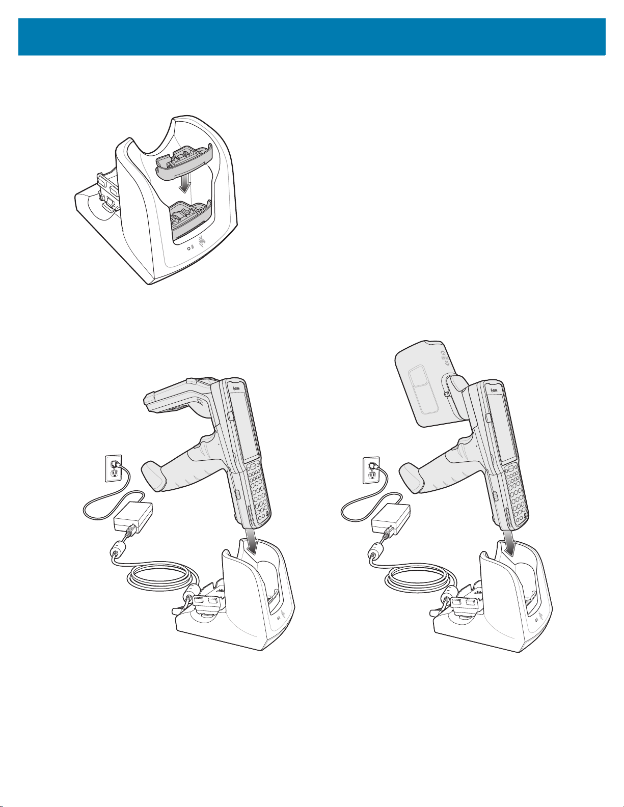
Adapter Installation
To install the MC33XX Charge Only Adapter into the MC32N0 Cradle:
1. Clean the MC32N0 cradle and contacts with an alcohol wipe, using a back and forth motion with your finger.
For more information about cleaning, see Troubleshooting.
Accessories
Figure 23 Clean MC32N0 Cradle
2. Peel and remove the adhesive from the back of the adapter.
Figure 24 Peel and Remove Adhesive
48
Page 49
Accessories
3. Insert the adapter into the MC32N0 cradle and adhere to the bottom of the cradle.
Figure 25 Insert Adapter into Cradle and Adhere
4. Insert the MC3300R device into the MC32N0 cradle.
Figure 26 Insert MC3300R device into MC32N0 Cradle
The MC3300R 5200 mAh PowerPrecision+ extended battery charges from 0% to 90% in less than 5.5 hours at
room temperature.
The MC32N0 5200 mAh PowerPrecision extended battery charges from 0% to 90% in less than 5.5 hours at room
temperature.
49
Page 50

Accessories
Charging Temperature
Charge batteries in temperatures from 0 °C to 40 °C (32 °F to 104 °F). Charging is intelligently controlled by the
MC3300R.
To accomplish this, for small periods of time, the MC3300R or cradle alternately enables and disables battery
charging to keep the battery at acceptable temperatures. The MC3300R or cradle indicates when charging is
disabled due to abnormal temperatures via its LED.
50
Page 51

MC3300R Rubber Boot
The rubber boot provides additional protection for the MC3300R.
NOTE: To function properly, remove the lower part of the rubber boot or the entire rubber boot before placing in
a charging cradle.
If the hand strap is attached, release the hand strap to install the rubber boot. After the rubber boot is
installed, reattach the hand strap.
To attach the rubber boot:
1. If the hand strap is attached, remove the hand strap.
2. Slide the battery end of the MC3300R into the bottom of the rubber boot.
Figure 27 Slide MC3300R into Bottom of Rubber Boot
Accessories
3. Grasp the top of the rubber boot and place over the top of the MC3300R.
4. Re-attach the hand strap (see Hand Strap on page 56).
Figure 28 Place Rubber Boot Over Top of MC3300R
51
Page 52

Fabric Holster
The Fabric Holster provides a soft holder for the mobile computer. It consists of a fabric mobile computer holder, a
detachable shoulder strap and a belt strap See figures below to attach the Fabric Holster to a belt and shoulder
strap.
Belt Strap
Attach the Fabric Holster to a belt or waist band.
Figure 29 Attach the Fabric Holster to a Belt
Accessories
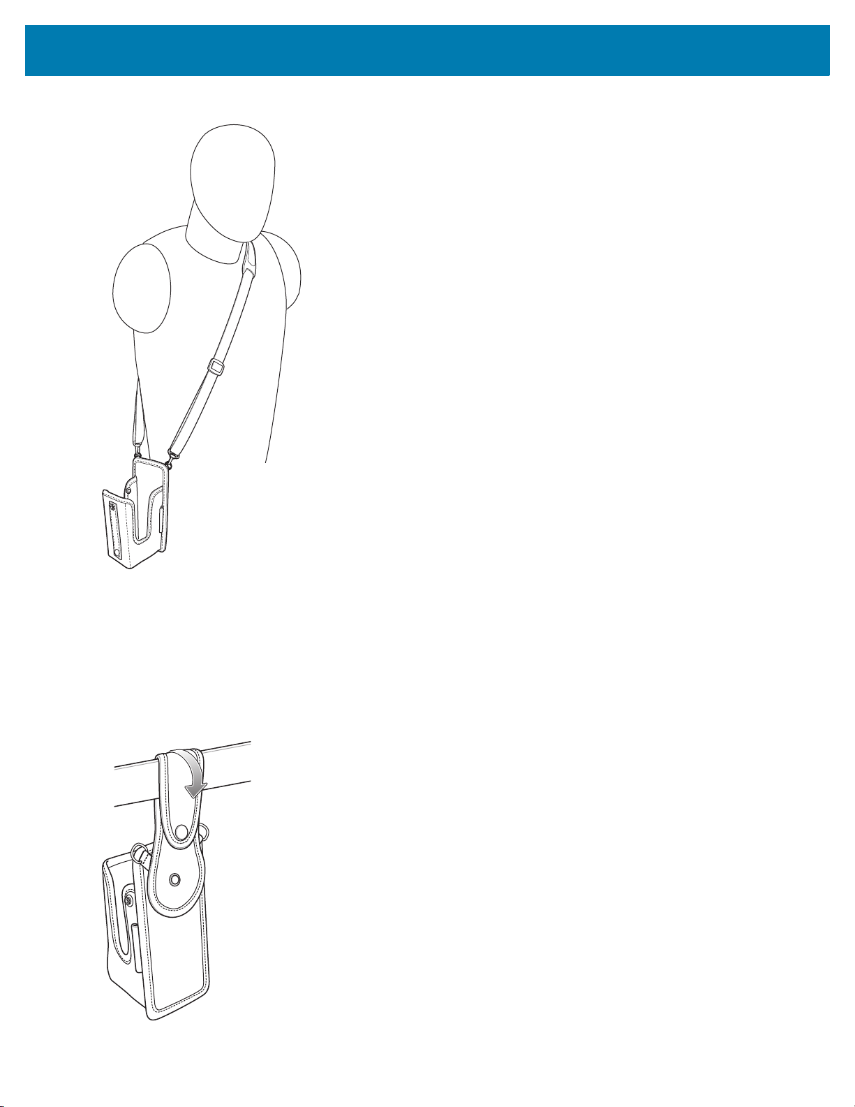
Shoulder Strap
Attach the fabric holster to a shoulder strap.
52
Page 53
Accessories
Figure 30 Attach Fabric Holster and Shoulder Strap
o
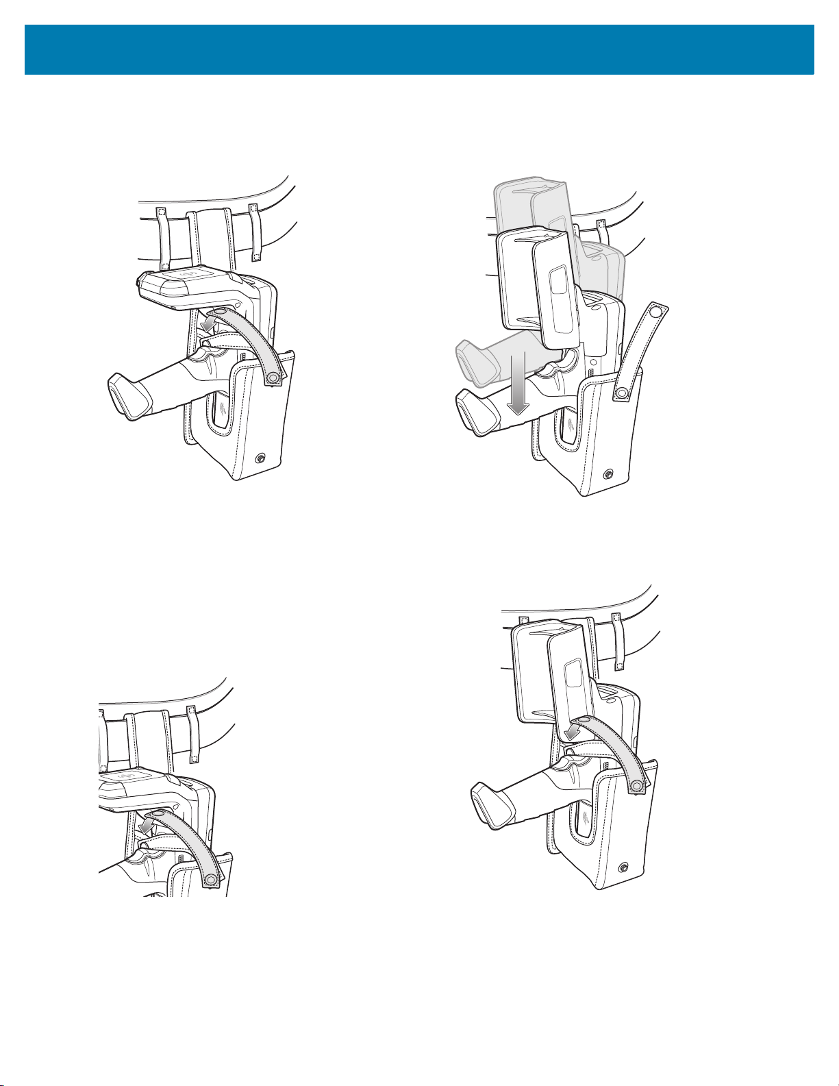
Using the Belt Strap
The Fabric Holster holds the MC3300R on a belt or waist band.
1. Secure the Belt Strap over the belt or waistband and snap into place.
Figure 31 Secure Belt Strap On Belt
53
Page 54
Accessories
2. To insert the MC3300R, slide the mobile computer (battery end first) into the Fabric Holster with the screen
facing the user.
Figure 32 Insert MC3300R
3. Secure the MC3300R with the restraining strap and place over the MC3300R to secure in place.
Figure 33 Secure with Strap
4. To remove the MC3300R, unsnap the restraining strap to release. Lift the MC3300R out of Fabric Holster.
Using the Shoulder Strap
1. Connect the clips on the shoulder strap to the rings on the fabric holster.
2. Place the shoulder strap over your head and rest on your shoulder.
54
Page 55

Figure 34 Shoulder Strap
Accessories
3. Lift the strap and insert the MC3300R into the holster.
4. Secure the strap to hold the MC3300R in place.
55
Page 56

Hand Strap
To install the hand strap:
1. Thread the lanyard loop through the opening near the base of the trigger handle.
Figure 35 Insert Loop Through Handle Slot
Accessories
2. Insert the top end of the hand strap through the loop.
Figure 36 Thread Hand Strap Through Loop
3. Thread the hand strap through the lanyard.
4. Pull the hand strap through the loop.
5. Thread the end of the hand strap with the tab through the slot on the bottom of the MC3300R.
56
Page 57
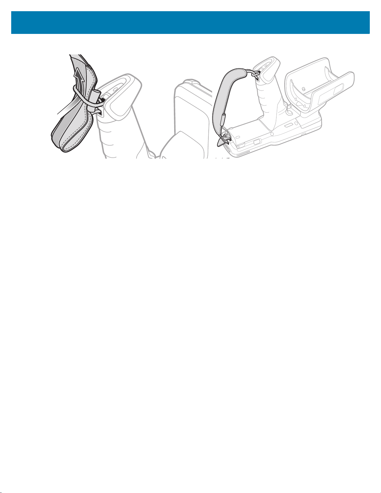
Accessories
Figure 37 Thread Tab Through Slot
6. Slide the tab through the slit in the hand strap so that the tip of the tab is facing away from the MC3300R.
57
Page 58

Zebra RFID Mobile Application for Android
Introduction
This chapter describes the enhanced version of the Zebra RFID Mobile Application for Android which
demonstrates MC3300R capability and tag operation functionality.
Requirements
Requirements for the Zebra RFID Mobile Application for Android are as follows:
• The recommended Android version on the mobile computer is Nougat version 7.1.x
• Zebra Enterprise RFID mobile computer - MC3300R
• Zebra RFID Manager APK
• Zebra RFID Mobile Application APK.
Zebra RFID Mobile Application for Android
This application runs on Android mobile devices and demonstrates MC3300R capability and tag operation
functionality.
The application allows for navigating to all screens at any time, however, some actions are not permitted while the
device is charging. These actions include any operation that involves Tag reading or writing (for example: Rapid
Read, Inventory, Locate Tag, etc.).
Navigate to all screens when the inventory/locate operation is in progress. When the operation is in progress, the
device displays Operation in Progress if additional operations are initiated.
Using the Zebra RFID Mobile Application for Android
To use this application for RFID operations:
1. Launch the Zebra RFID Mobile Application for Android on the mobile device.
2. Select Settings > Advanced Reader Options > Antenna. Power Level is set to 27.0 dBm by default.
However, it is shown as 270 dbm because the value used is in units of tens of dBm. Japan units are set to a
different default power level depending on the SKU type.
3. Before using the device and if the region is not set, set the region in which the device is operating. To set the
region, open the application and select Settings > Regulatory (see Power Management on page 88).
58
Page 59

Zebra RFID Mobile Application for Android
Demo Application Screens
Home Screen
To access the Zebra RFID Mobile Application for Android, touch the Zebra RFID Reader icon on the mobile device
to display the Home screen. Swipe right from the left side of the screen to display the RFID Reader Menu. Tap any
menu item to access its screen.
Figure 38 Home and Menu Screens
59
Page 60

Zebra RFID Mobile Application for Android
Rapid Read
Tap Rapid Read from the Home or Menu screen.
Figure 39 Rapid Read Screen
The Rapid Read and Inventory screens display the following data (see Inventory on page 61).
• Total tag count
• Unique tag count
• Read time (mm:ss)
• Tag read rate (tags/sec).
Rapid Read and Inventory screens are two different views of the inventory operation on the reader. The Start/Stop
functionality can be used interchangeably on both screens. For example, when operation starts on the Rapid Read
screen and you navigate to the Inventory screen, the button available on the Inventory screen is Stop. The same
is true when the operation starts on the Inventory screen. During the rapid read process, you can navigate to the
Inventory screen to view tag details along with tag counts for each tag. The statistics displayed are maintained on
the Rapid Read and Inventory screens regardless of the screen used to start the process.
Select Start to start the rapid read inventory operation. Select Stop to stop inventory operation.
NOTE: The scan trigger on the MC3300R can also start and stop the inventory operation. Press the trigger to
start, continue to hold and release to stop.
Moving to another screen does not halt the operation. However, attempting to make changes or perform another
operation while rapid read is in process results in an error.
60
Page 61

Zebra RFID Mobile Application for Android
Memory
Bank
Search
Icon
Locate
Icon
Inventory
Select Inventory from the Home or Menu screen.
Figure 40 Inventory Screen
Tag reading is started and stopped on this screen as well as on the Rapid Read screen (see Rapid Read on page
60). When the process starts, tag information displays on the screen.
Select Start to start the rapid read inventory operation. The Start button changes to Stop. Tap Stop to stop the
read inventory operation.
NOTE: The scan trigger on the MC3300R can also start and stop the inventory operation. Press the trigger to
start, continue to hold and release to stop.
The tag ID selected displays on the Access, Locate Tag, and Pre Filters screen when navigating to that screen.
After selecting tag, tap on the action bar Locate icon to go to the Locate screen. The second screen displays the
tag which is fully convertible to ASCII format. ASCII mode may be enabled by selecting Settings > Application.
61
Page 62

Zebra RFID Mobile Application for Android
Inventory Screen Features
Table 11 Inventory Screen Features
Item Description
Action Bar
Tags Tap Memory Bank to select one of the following memory bank options from the
drop-down menu:
• None - Defaults to EPC.
• User - Allows reading user memory bank data when the tag is inventoried.
• Reserved - Allows reading reserved memory bank data when the tag is inventoried.
• TID - Allows reading TID memory bank data when the tag is inventoried.
• EPC - Allows reading EPC memory bank data when the tag is inventoried.
When the next inventory operation starts, the details from the selected memory bank
displays. This menu is inactive if there is an ongoing operation on the connected
reader.
• Default Display - None.
Search Tap the Search icon and enter a tag ID. Tags that match the entry display in the content
area.
62
Page 63

Zebra RFID Mobile Application for Android
Table 11 Inventory Screen Features (Continued)
Item Description
Power Management Icon indicates if Dynamic Power is on. See Power Management on page 88.
Tap the Power Management icon to open the Battery Status screen.
Content Area
(select a tag)
Content Area
(select a tag)
Tapping a Tag ID highlights the tag. The highlighted Tag ID is populated on the Tag
Location text area as well as the Tag Pattern area in the Access Control screen. Tap
Start to start searching for the tag. See Tag List Match Mode Operation on page 63 for
more details. From this screen, return to the Menu or go to the Home screen and select
Locate Tag.
The tags displayed in this area are based on the option selected from the memory bank.
Tap the tag ID to expand details about the tag. Tap the tag ID again to collapse details.
Example Default Tag Display:
Tag IDTag Count
AD99 15404190725965400404
Example Expanded Tag Display:
Note: Expanded tag detail can only display when the inventory operation is stopped.
Memory bank data is shown only when inventory is complete.
Tag IDTag Count
AD99 15404190725965400404
EPC MEMORY3000
RSSI
-50
Phase
1800
USER
1122334455667788AABBCCDDEEFF
1122334455667788AABBCCDDEEFF
1122334455667788AABBCCDDEEFF
Tag List Match Mode Operation
When Tag List Match Mode is checked on the Application screen (Application on page 76), the application
identifies tags from a given set of tags in csv tag list format (comma separated values file). The contents of the csv
file displays on the Inventory screen. By default, the application shows friendly names from csv files.
Before the inventory starts, the count is zero. Figure 41 displays drop-down menu choices. Select an option to
display the type of tags to show when the inventory starts.
All: Sample 4 Inventory List: Tag List Enabled; All Tag Option Selected on page 68
Matching: See Sample 1 Inventory List: Tag List Enabled; Matching Tag Option Selected on page 65.
Missing: See Sample 2 Inventory List: Tag List Enabled; Missed Tag Option Selected on page 66.
Unknown: Sample 3 Inventory List: Tag List Enabled; Unknown Tag Option Selected on page 67
63
Page 64

Figure 41 Tag List Menu
Zebra RFID Mobile Application for Android
Sample Contents of Taglist.csv File
The csv file should contain only alphanumeric characters in the tag column. If there are any special characters, the
row is discarded.
The Taglist.csv file must be located inside the rfid folder which must be manually created at the Android device root
directory.
NOTE: The folder name must be all lower case (for example, rfid and not RFID).
Figure 42 Taglist.csv File Contents
64
Page 65
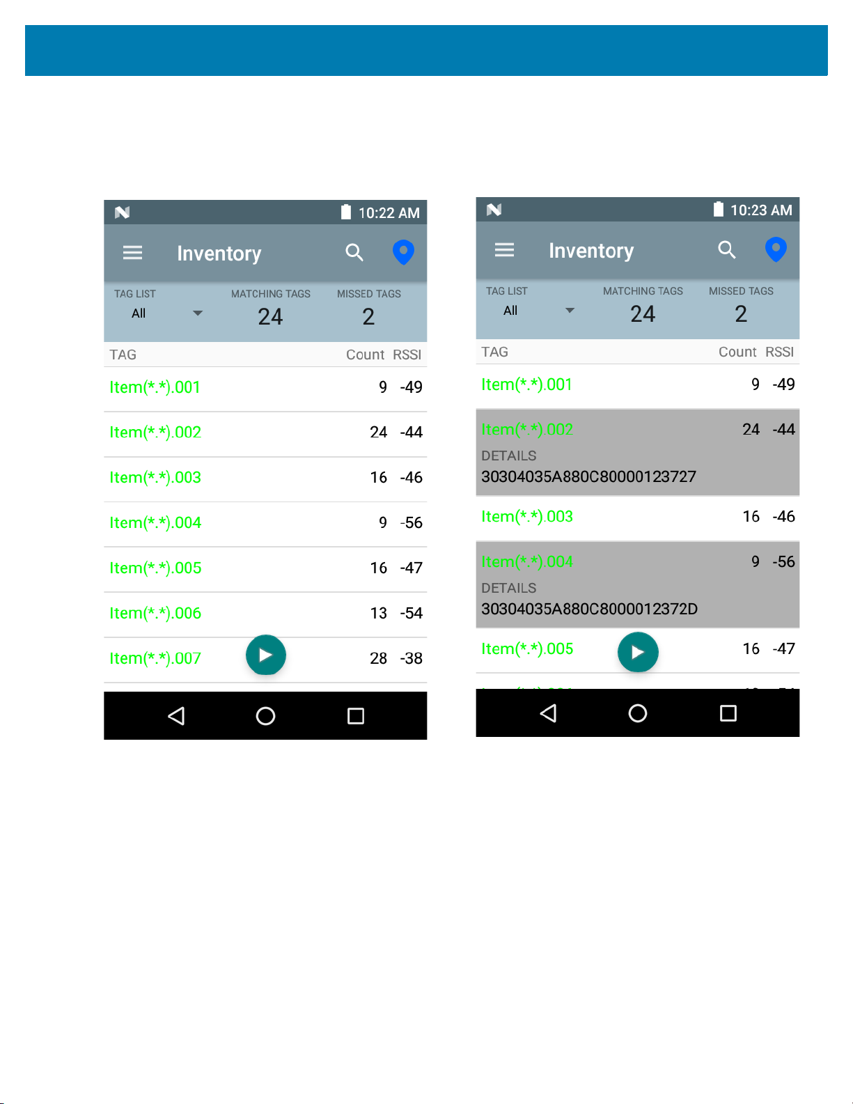
Zebra RFID Mobile Application for Android
Sample 1 Inventory List: Tag List Enabled; Matching Tag Option Selected
When inventory starts, the application only displays the tag reads that match the tags in the taglist.csv file.
Matching tags display in green. Select any tag read to show the matching tag details in the csv file.
Figure 43 Matching Taglist.csv File Contents
65
Page 66

Zebra RFID Mobile Application for Android
Sample 2 Inventory List: Tag List Enabled; Missed Tag Option Selected
When inventory starts, the application only displays the tag reads that are missed and included in the taglist.csv
file. Missed tags display in red. Select any tag to show the missed tag details in the csv file.
Figure 44 Missed Taglist.csv File Contents
66
Page 67

Zebra RFID Mobile Application for Android
Sample 3 Inventory List: Tag List Enabled; Unknown Tag Option Selected
When inventory starts, the application only displays tags that were read but not included in the taglist.csv file.
Unknown tags display in gray. Select any tag to show the unknown tag details.
Figure 45 Unknown Tags
67
Page 68

Zebra RFID Mobile Application for Android
Sample 4 Inventory List: Tag List Enabled; All Tag Option Selected
When inventory starts, the application displays the tags for all of the options:
• Tag reads that match the tags in the taglist.csv file. Matching tags display in green. Select any tag read to
show the matching tag details in the csv file.
• Tag reads that are missed and included in the taglist.csv file. Missed tags display in red. Select any tag to
show the missed tag details in the csv file.
• Tags that were read but not included in the taglist.csv file. Unknown tags display in gray. Select any tag to
show the unknown tag details.
Figure 46 All Tags
68
Page 69

Zebra RFID Mobile Application for Android
Sample 5 Tag List Matching Selected; Show Friendly Not Names Selected
When inventory starts, the application displays the tags for selected options from All, Matching, Missing, or
Unknown. Application shows friendly names (i.e., Tag details instead of EPC) on screen.
Figure 47 Show Friendly Names Enabled
69
Page 70

Zebra RFID Mobile Application for Android
Sample 6 Exporting Data - Tag List Matching Selected
The Application screen on page 76 has the option to Export Data. If the option is checked, data is exported when
the inventory stops. The tag content area is exportable to a file. For example, when Matching is selected from the
menu to display only matching tags in the tag content area, the matching data can be exported to a file. The
exported csv file includes the matching, missing, and unknown tag count shown in Figure 48.
Figure 48 Exported File Content
70
Page 71

Zebra RFID Mobile Application for Android
Unique Tag Reporting
When Unique Tag Reporting is enabled on the Tag Reporting screen on page 87, the reader reports only unique
tags based on the options below.
• When the Matching option is selected (see Sample 1 Inventory List: Tag List Enabled; Matching Tag
Option Selected on page 65) the tag count cannot be greater than one because the unique tags are only
reported one time.
• When the Matching option is not selected, the list displays unique and total reads. The tag count cannot
be greater than one because the unique tags are only reported one time.
71
Page 72

Zebra RFID Mobile Application for Android
Figure 49 Tag List Mode Enabled
Figure 50 Tag List Mode - Disabled
72
Page 73
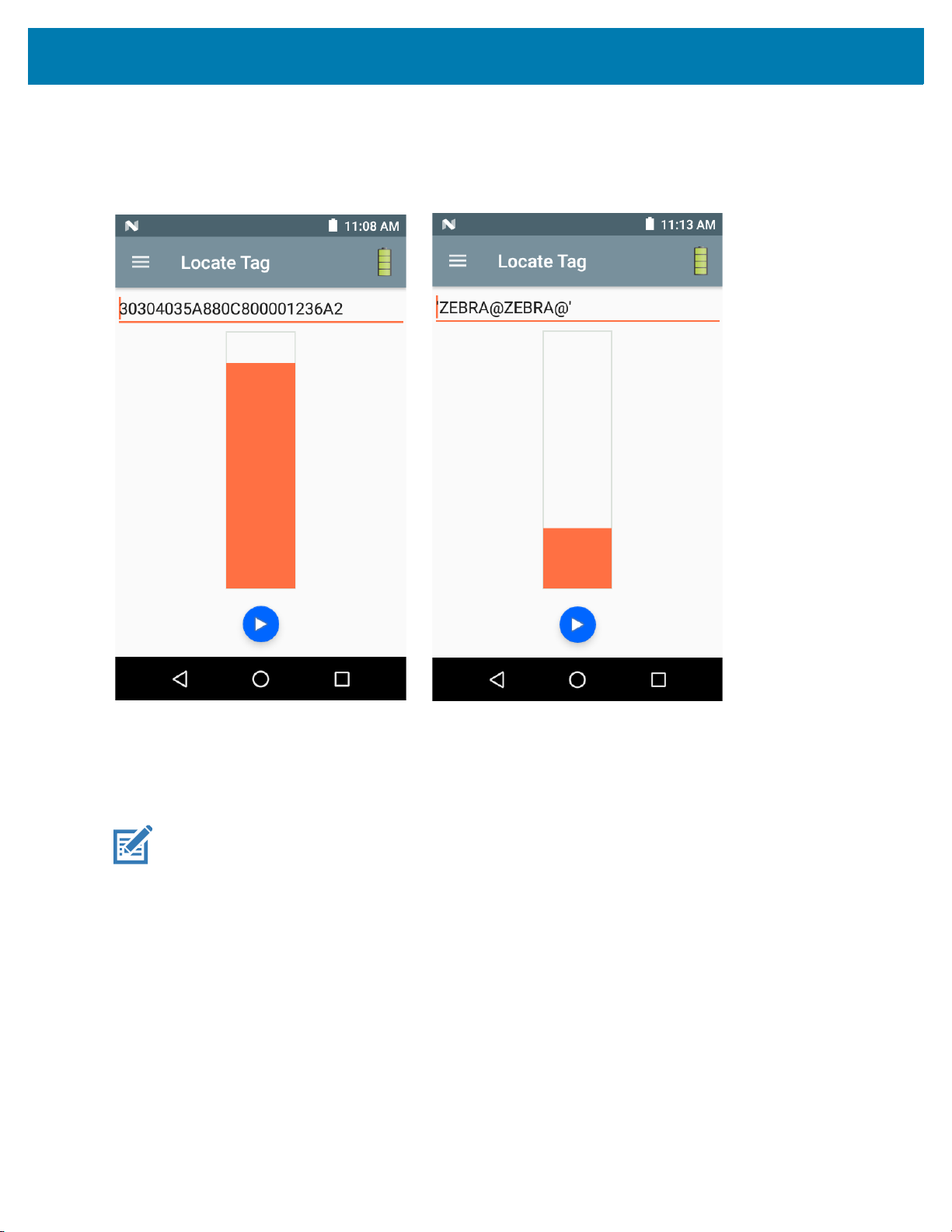
Zebra RFID Mobile Application for Android
Locate Tag
Tap Locate Tag from the Home or Menu screen.
Figure 51 Locate Tag Screen
On this screen, enter the Tag ID in the text area or select a tag from the Inventory screen to pre-populate the Tag
ID to search.
Tap Start to start the locate tag operation. Tap STOP to stop. The MC3300R trigger can also be used to start and
stop the operation.
NOTE: The scan trigger on the MC3300R can also start and stop the inventory operation. Press the trigger to
start, continue to hold and release to stop.
The color bar on the display shows the relative distance of the tag.
When the locate tag operation starts, moving to another screen does not stop the operation until Stop is selected.
73
Page 74

Settings
Figure 52 Settings Screen
Zebra RFID Mobile Application for Android
Table 12 Settings Screen Options
Settings Option Description Page
Readers List Displays connected MC3300R.
Application Displays reader connection, notification, and data export settings.
Profiles
Displays Fastest Read, Cycle Count, Dense Readers, Optimal
6-75
6-76
6-77
Battery, Balanced Performance, User Defined and Reader Defined
profiles.
Regulatory Allows region and channel selections.
Battery Displays the MC3300R battery status.
Beeper Use to turn the beeper on/off, and set volume.
LED Enables/Disables MC3300R tag read LED indicator.
Advanced Reader Options
Antenna Displays antenna power lever and link profile.
Singulation Control Displays Session, Tag Population, Inventory State and SL Flag.
Start\Stop Triggers Allows Start and Stop button control.
6-80
6-81
6-82
6-83
6-83
6-85
6-86
74
Page 75

Zebra RFID Mobile Application for Android
Table 12 Settings Screen Options (Continued)
Settings Option Description Page
Tag Reporting Support for reporting unique tags as part of tag reporting options.
Power Management Turns Dynamic Power Optimization on and off.
Save Configuration Ability to save all settings: Antenna, Singulation, Tag Reporting,
Start/Stop trigger, Beeper Volume, and Regulatory.
Note: The settings are also automatically saved when changes are
made.
Readers List
From the Settings screen, select Readers List.
Figure 53 Settings - Readers List Screen
6-87
6-88
6-89
Tap a reader name from the Readers List to establish a session with the selected reader. Tap again to terminate
the session.
75
Page 76

Application
Zebra RFID Mobile Application for Android
From the Settings screen, select Application
Figure 54 Settings - Application Screen
.
The application always detects the MC3300R Mobile Computer.
• Auto Reconnect Reader - When checked, the device connects to the RFID service which manages the
connection to the reader.
• Export Data - When checked, the application writes the inventoried RFID data to a file when the inventory
operation stops. On Android platforms the file is saved in a fixed directory. Check the files in file browsing
in the Inventory directory (Sdcard/inventory/<files>). The files may be copied to a PC.
• Tag List Match Mode - Check to enable matching mode.
• Show friendly names - Check to show the tag's friendly names instead of EPC ID. Show friendly names
is only available when Tag List Match Mode is enabled.
• ASCII Mode - Displays tag ID in ASCII format. If the full tag ID or memory bank data is convertible to ASCII
format, then the application only shows the same. Inventory, Locate, Access, and Pre Filters show ASCII
mode represented data in respective sections.
76
Page 77

Zebra RFID Mobile Application for Android
Profiles
To display the list of profiles, tap on Settings > Profile.
• The currently selected profile is highlighted in orange.
• Tap profile item to expand the profile and view applicable configurations.
• Profiles can be selected or disabled by using the slider switch to the right of the profile name.
NOTE: If Power Level, Link Profile, Session, or Dynamic Power are modified from each respective screen, then
the currently selected profile changes to User Defined profile and profile item values are modified with same
values.
Profile setting options are as follows:
Fastest Read - Read as many tags as fast as possible.
•
• Cycle Count - Read as many unique tags as possible.
• Dense Readers - Use when there are multiple readers within close proximity.
• Optimal Battery - Provides best battery life.
• Balanced Performance - Maintains balance between performance and battery life.
• User Defined - Custom profile used for custom requirements.
• Reader Defined - Maintains reader configurations.
77
Page 78

Figure 55 Profiles Settings
Zebra RFID Mobile Application for Android
78
Page 79

Zebra RFID Mobile Application for Android
79
Page 80

Zebra RFID Mobile Application for Android
Regulatory
The region drop-down displays the current region to which the device is set. Choose the correct region before
using the device.
• Channel Selection is allowed only for the regions that allow channel setting.
• Supported regions are reported by the MC3300R.
• If the region is not configured on the MC3300R, the Regulatory screen is the first screen displayed after
connecting to the MC3300R.
NOTE: Select only the country in which the device is used.
Figure 56 Settings - Regulatory
80
Page 81

Zebra RFID Mobile Application for Android
Battery
This screen displays the status of the battery. The battery levels are as follows:
• Level is high (green) Status - Battery is mostly charged
• Critical (red) Status - Battery Level is Critical
• Low (orange) Status - Battery Level Low
• Reader is not connected (grey) - No Active Connection.
The battery percentage is provided as text above the battery indicator and the status field below the battery
indicator provides charging/discharging information.
Figure 57 Settings - Battery
81
Page 82
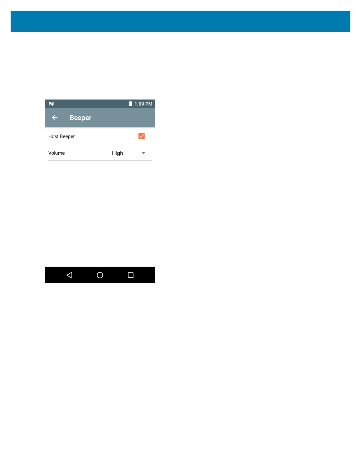
Zebra RFID Mobile Application for Android
Beeper
The Beeper screen displays the current beeper settings. To turn the beeper Off, un-check the Host Beeper check
box. To set the beeper volume, select the Volume drop-down menu and select High, Medium or Low.
The mobile computer provides a beep indication for inventory and access operations.
Figure 58 Settings - Host Beeper
82
Page 83
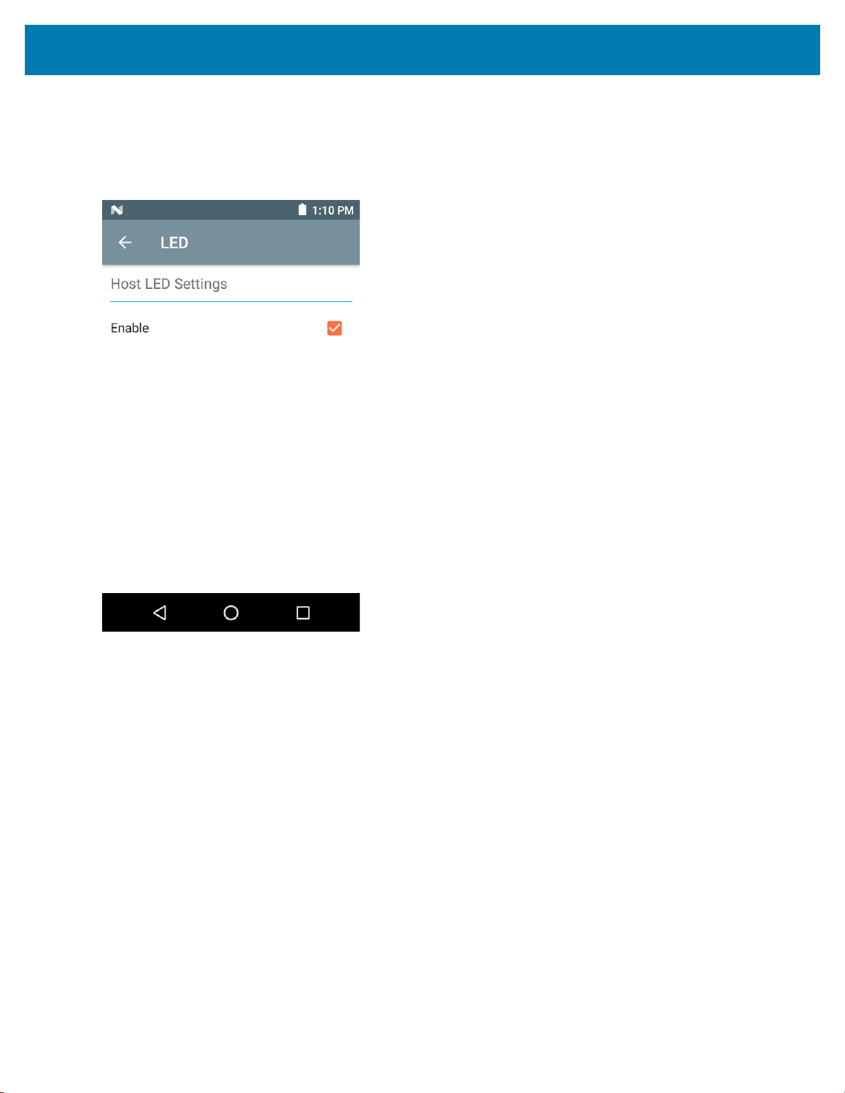
Zebra RFID Mobile Application for Android
LED
The LED screen displays the current host LED settings. To enable the mobile computer LED, select the Enable
check box. During inventory and access related operations, the LED blinks green for a successful read.
Figure 59 Settings - Host LED
Antenna
To access the Antenna screen, go to: Settings > Advanced Reader Options > Antenna. The Antenna screen
displays the following:
• Power Level - Displays the current selection and a text box for available power levels (as reported by the
MC3300R). The default setting is 27.0 dBm (shown as 270; the value displayed is in units of tens of dBm).
Japan units are set to a different default power level depending on the SKU type.
The minimum power level when DPO is enabled is 3.1 dBm. When DPO is disabled, the minimum power
level is 0 dBm.
• Link Profile - Displays the current selection and includes a drop-down list of available link profiles
(reported by MC3300R).
Link Profile display format is as follows: Return link bit data rate in bis per second (e.g., 60000 -> 60 Kbs);
Miller Value (e.g., MV_4 -> Miller 4); thus profile name M4 240K (240K becomes BLF) modulation type (PR
ASK is the only one supported).
• PIE value has no units and is either 1500 and 2000 minimum.
• Tari applicable Tari value in thousands of micro seconds (e.g., 6250 -> 6.25 microseconds).
• The Power Level and Link Profile are blank when there is no connection to the reader.
83
Page 84
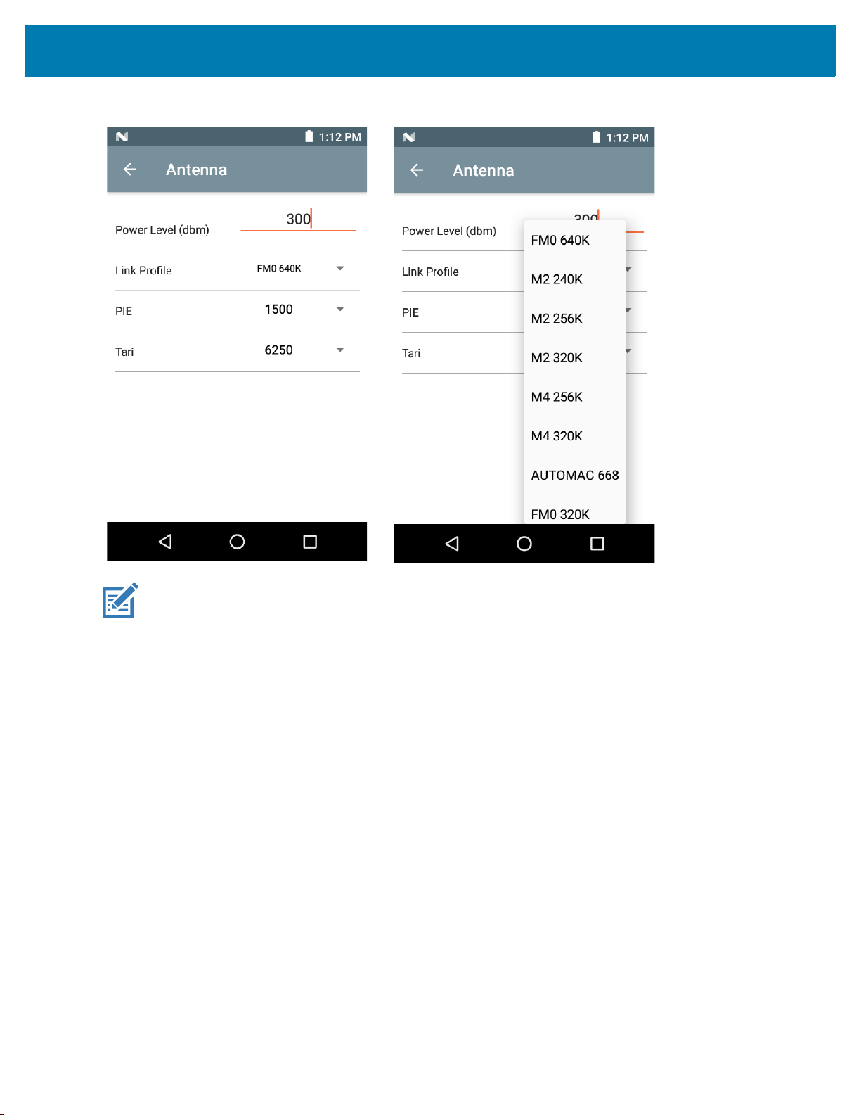
Figure 60 Antenna Screen
Zebra RFID Mobile Application for Android
NOTE: The Power Level and Link Profile are blank when there is no connection to the reader.
84
Page 85

Zebra RFID Mobile Application for Android
Singulation Control
To access Singulation Control, go to: Settings > Advanced Reader Options > Singulation Control. View or
configure the singulation control settings for each antenna.
• Session - The drop-down list includes the available session options (S0, S1, S2, S3).
• Tag Population - A numeric value of the estimated number of tags in the Field of View (FOV). Values
shown are 30, 100, 200, 300, 400, 500, 600.
• Inventory State - State A, State B, AB Flip.
• SL flag - ALL, DEASSERTED, ASSERTED.
Figure 61 Singulation Control Screen
85
Page 86

Zebra RFID Mobile Application for Android
Start\Stop Triggers
To access the Start\Stop Triggers screen, go to: Settings > Advanced Reader Options > Start\Stop Triggers.
The Start Trigger Periodic displays the Period input box (in milliseconds).
The Stop Trigger Duration, Tag Observation and N attempts display numeric value input boxes. All time entries
are in milliseconds.
All the required details for saving triggers to the reader must be entered or the application does not save the trigger
settings to the reader.
Figure 62 Start/Stop Triggers Screen
Required input for Start/Stop Trigger settings are as follows:
• Start Trigger
• Immediate (default)
• Hand-held - Select either the Trigger Pressed or Trigger Released check box.
• Periodic - Enter the period of time in milliseconds.
• Stop Trigger
• Immediate (default)
• Hand-held - Select either the Trigger Pressed or Trigger Released check box along with Timeout in
milliseconds.
• Duration - Enter duration in milliseconds.
• Tag Observation - Enter the tag count along with timeout in milliseconds.
• N Attempts - Enter the number of attempts along with timeout in milliseconds.
If the start trigger type is Hand-held trigger (pressed or released), the application sets the repeat for the operation
to ensure the use case if repeated operations can be demonstrated.
if any trigger is defined as Hand-held, then the application does not act on immediate trigger type for a Hand-held
trigger action.
86
Page 87
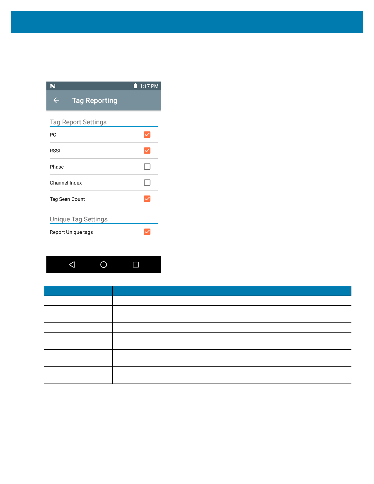
Zebra RFID Mobile Application for Android
Tag Reporting
To access Tag Reporting, go to: Settings > Advanced Reader Options > Tag Reporting.
Figure 63 Tag Reporting Screen
Table 13 Tag Reporting Screen Options
Option Description
PC Select to allow reporting the PC as part of the Tag Data.
RSSI Selection indicates whether or not the RSSI (Received Signal Strength Indication) is
reported as part of the Tag Data.
Phase Select to indicate whether or not the Phase is reported as part of the Tag Data.
Channel Index Select to indicate whether or not the Regulatory Channel Index is reported as part of
the Tag Data.
Tag Seen Count Select to indicate whether or not the Tag Seen Count is reported as part of the Tag
Data.
Report Unique Tags When this option is enabled, the reader reports only unique tag reads.The Unique Tag
reporting feature can be enabled when using Tag List Match mode.
87
Page 88
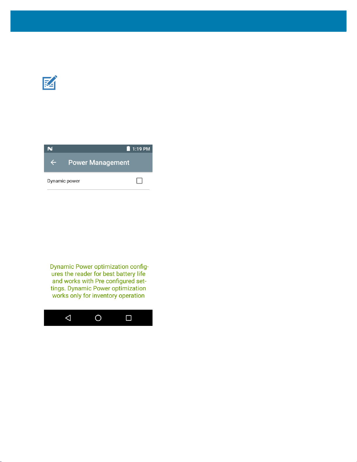
Zebra RFID Mobile Application for Android
Power Management
This screen provides an option to enable Dynamic Power Optimization (DPO) in the reader. Enabling DPO
enhances battery life during inventory operations.
NOTE: DPO is enabled by default. It is not necessary to disable DPO when executing access operations or
using filters because DPO is automatically disabled and when the operation is complete, it is automatically
enabled.
If Dynamic Power is On, a green battery icon appears in the title bar of the application. Tapping on this opens the
Battery Status screen.
To access Power Management, go to: Settings > Advanced Reader Options > Power Management.
Figure 64 Power Management Screen
88
Page 89

Zebra RFID Mobile Application for Android
Save Configuration
To access Save Configuration, go to: Settings > Advanced Reader Options > Save Configuration. This screen
is used to save the settings and displays the current settings on the MC3300R.
The settings are saved on MC3300R until a reset to factory defaults is performed on the unit (see Settings on page
74).
The Tag Pattern area is automatically filled in when a tag is selected in the Inventory screen.
Figure 65 Save Configuration Screen
89
Page 90

Zebra RFID Mobile Application for Android
Advanced Option Icon
Access Control
Figure 66 Access Control Screens - Read/Write, Lock, Kill
90
Page 91

Zebra RFID Mobile Application for Android
The Tag Pattern area is automatically filled in when a tag is selected in the Inventory screen.
Read/Write
The Read/Write access operation is simplified with offset and length fields are hidden, the user can tap the
more/advanced options icon to see offset and length fields. Tap the icon again to hide the advanced options.
Memory Bank options now have extended menu options to choose directly interested area of memory bank. This
avoids typing of offset and length etc.
Read/Write options are:
• Tag ID & Password values are in hex. Tag ID is edited
• Memory Bank options - EPC, TID, USER, PC and CRC, Access Password, Kill Password
• Offset and Length values are in 16-bit words. This is only available after tapping the Advance Options
icon. To toggle visibility, tap Advanced Options again.
• Access operation screen maintains edited tag ID.
Lock
Lock privilege options are as follows:
• Read and Write
• Permanent Lock
• Permanent Unlock
• Unlock.
Kill
Permanently renders the tag unusable. A Kill Password must be provided.
91
Page 92

Pre Filters
Figure 67 Pre Filters Screen
Zebra RFID Mobile Application for Android
The Pre Filters screen is simplified with Tag pattern (EPC ID) and enable filter option. Tap the more/advanced
icon to get full control of various fields related to pre filters. Tap the icon again to hide the advanced options.
Up to two of the following Pre Filters may be enabled.
• Memory Bank - EPC, TID and USER.
• Offset - The offset in the memory bank is specified in words.
• Select non matching TAGs - Inventory shows tags which are not matching with Tag pattern entered.
• Action:
• INV A NOT INV B or ASRT_SL_NOT_DSRT_SL
• INV A or ASRT SL
• NOT INV B or NOT DSRT SL
• INV A2BB2A NOT INV A or NEG SL NOT ASRT SL
• INV B NOT INV A or DSRT SL NOT ASRT SL
• INV B or DSRT SL
• NOT INV A or NOT ASRT SL
• NOT INV A2BB2A or NOT NEG SL
• Target - SESSION S0, SESSION S1, SESSION S2, SESSION S3 & SL FLAG.
About
This screen displays version information as reported by the MC3300R.
92
Page 93

Figure 68 About Screen
Zebra RFID Mobile Application for Android
93
Page 94

RFID Manager
Introduction
The Zebra RFID Manager application allows the user the perform various management functions on the RFID
reader module in the MC3300R device including firmware update, power control for the RFID Radio, resetting the
RFID module to factory defaults, and various other functions.
NOTE: Some screens shown in this guide may differ from the actual screens shown on the device. Screens are
subject to change with future releases.
Using the RFID Manager for Android
To use this application for RFID operations:
1. Launch the RFID Manager application for Android on the mobile device.
2. During initial use, set the region in which the device is operating. To set the region, open the application and
select Settings > Regulatory.
NOTE: If the RFID Demo application or partner application is connected to the MC3300R, the RFID Manager
can still perform all management functions, however care should be used as to not interfere with any ongoing
operational behavior of the device (e.g., inventory, setting parameters, etc.).
Connection Status
Reader Status
By default, the RFID Reader is powered on and in the Ready. If the MC3300R RFID Radio is not powered on, the
Reader Status displays Off.
94
Page 95

RFID Manager
Figure 69 Reader Connection Status Screens
95
Page 96
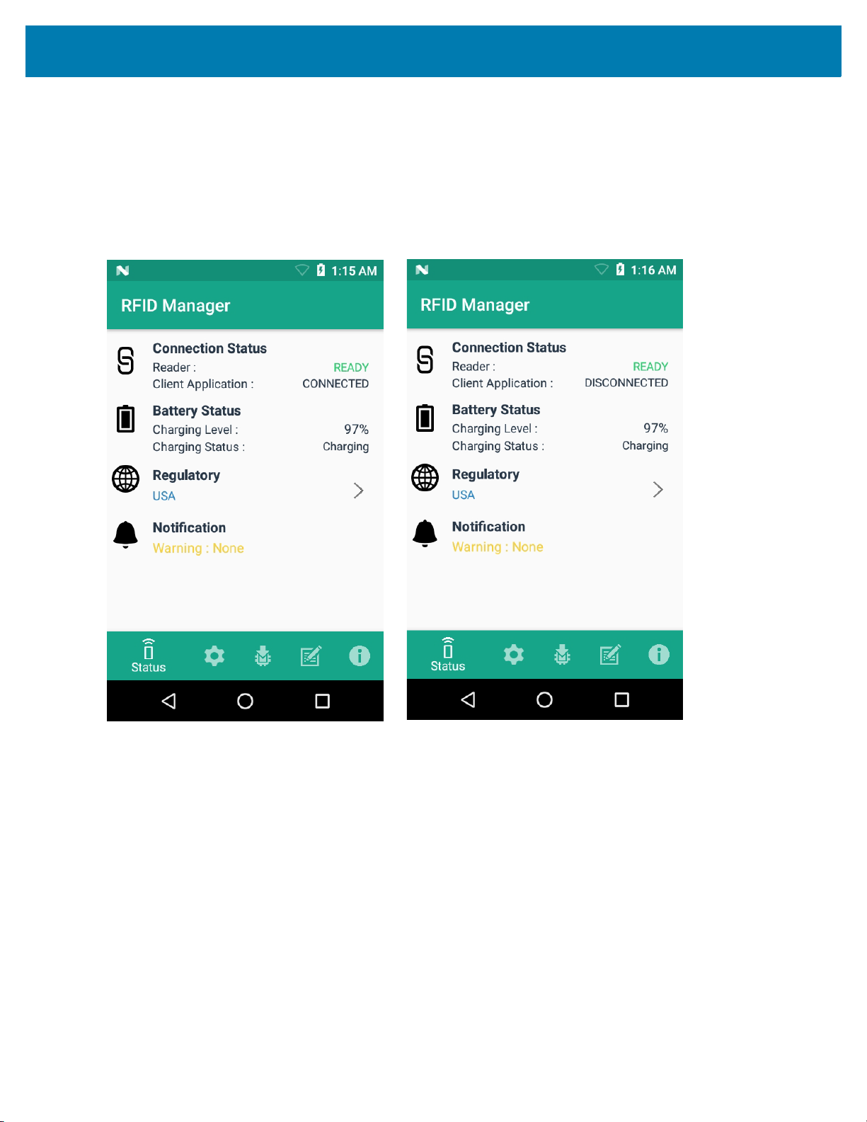
RFID Manager
Client Application Status
If the MC3300R RFID Reader Status is Ready:
1. Launch the application manually.
2. On the Home Screen under Connection Status > Client Application, it indicates if the client application is
Connected or Disconnected to the MC3300R RFID Reader.
Figure 70 Client Application Status Screens
The Battery Status contains the battery Charging Level percentage and the Charging Status (Charging or
Discharging).
96
Page 97

RFID Manager
RFID Regulatory
To set the region, select the Regulatory arrow button to open the Regulatory screen. Select the Region and
Channel Selection settings and tap the Apply button. The Region drop-down displays the current region to which
the device is set. Choose the correct region before using the device.
NOTE: The Region and Channel Selection requires setup before the initial use only. However, if a
Reset to Factory Defaults operation is conducted on the MC3300R RFID Reader, the operation
removes the Region and Channel and needs to be set again.
NOTE: Select only the country in which you are using the device.
• Channel Selection is allowed only for the regions that allow channel setting.
• Supported regions are those reported by the specific MC3300R Model.
• If the region is not configured on the MC3300R, the Regulatory status shows as NA.
• A customer application can also set the region and configuration programmatically.
Figure 71 Regulatory Screens
97
Page 98
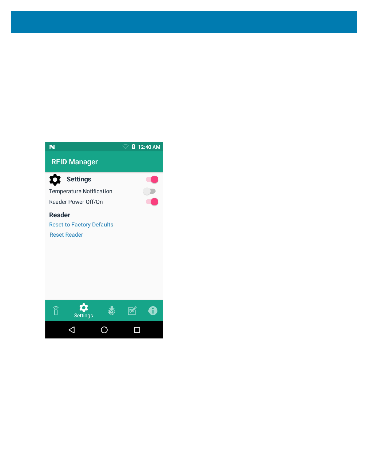
RFID Manager
Settings
To display Settings, select the Settings icon located on the bottom tool bar.
Turn on the Settings slider switch control to enable control of setting options.
Setting options are as follows:
• Temperature Notification – If enabled, a temperature high and critical notification appears with
temperature level indications.
• Reader Power Off/On - If enabled, the MC3300R RFID Radio is powered on. When the MC3300R RFID
radio is powered off, no RFID operations are supported.
Figure 72 Settings Screen
98
Page 99

RFID Manager
• Reset to Factory Defaults - Select Reset to Factory Defaults to reset all configuration and region
settings to factory default settings. When selected, the RFID reader internally reboots and a window
message displays after successful operation.
Figure 73 Reset to Factory Defaults Screen
• Reset Reader - Select Reset Reader to perform a reader restart. When selected, the reader reboots and
a window message displays after successful operation. Reader status confirmation is located under
Home > Status.
Figure 74 Reader Reset Screen
99
Page 100

RFID Manager
Firmware Update
A product code update, bootloader, and radio update may be performed using the firmware update screen.
NOTE: More than 15% battery level is required to perform a Firmware Update.
To perform a firmware update:
1. Copy the RFD file into the MC3300R SD card. One method is through the abd command (abd push
<firmware>/sdcard).
NOTE: The MC3300R must have USB Debugging enabled in Developer Options for adb commands to work
properly.
2. Browse for the firmware RFD file, by clicking on the folder icon.
NOTE:
3. Select the required RFD file, from File View menu. When the file is selected, the application returns to update
screen.
Figure 75 Transferring Files for Firmware Update
100
 Loading...