


SMARTMU
for Version 3.0.1
Administrator Guide
for
Android ™
MN-003325-01

Copyright
© 2018 ZIH Corp. and/or its affiliates. All rights reserved. ZEBRA and the stylized Zebra head are trademarks of
ZIH Corp., registered in many jurisdictions worldwide. All other trademarks are the property of their respective
owners.
COPYRIGHTS & TRADEMARKS: For complete copyright and trademark information, go to www.zebra.com/
copyright.
WARRANTY: For complete warranty information, go to www.zebra.com/warranty.
END USER LICENSE AGREEMENT: For complete EULA information, go to www.zebra.com/eula.
Terms of Use
• Proprietary Statement
This manual contains proprietary information of Zebra Technologies Corporation and its subsidiaries
(“Zebra Technologies”). It is intended solely for the information and use of parties operating and
maintaining the equipment described herein. Such proprietary information may not be used, reproduced,
or disclosed to any other parties for any other purpose without the express, written permission of Zebra
Technologies.
• Product Improvements
Continuous improvement of products is a policy of Zebra Technologies. All specifications and designs are
subject to change without notice.
• Liability Disclaimer
Zebra Technologies takes steps to ensure that its published Engineering specifications and manuals are
correct; however, errors do occur. Zebra Technologies reserves the right to correct any such errors and
disclaims liability resulting therefrom.
• Limitation of Liability
In no event shall Zebra Technologies or anyone else involved in the creation, production, or delivery of the
accompanying product (including hardware and software) be liable for any damages whatsoever
(including, without limitation, consequential damages including loss of business profits, business
interruption, or loss of business information) arising out of the use of, the results of use of, or inability to
use such product, even if Zebra Technologies has been advised of the possibility of such damages. Some
jurisdictions do not allow the exclusion or limitation of incidental or consequential damages, so the above
limitation or exclusion may not apply to you.
Revision History
Changes to the original guide are listed below:
Change Date Description
-01 Rev A 5/2018 Initial release.
2

Table of Contents
Copyright ........................................................................................................................................... 2
Terms of Use .................................................................................................................................... 2
Revision History ................................................................................................................................ 2
About This Guide
Introduction ....................................................................................................................................... 5
Product Support ................................................................................................................................ 5
Chapter Descriptions ........................................................................................................................ 5
SmartMU Use Cases ........................................................................................................................ 6
Notational Conventions ..................................................................................................................... 8
Provide Documentation Feedback .................................................................................................... 8
Using SmartMU
Introduction ....................................................................................................................................... 9
Opening SmartMU .......................................................................................................................... 10
Home Screen .................................................................................................................................. 11
Status ........................................................................................................................................ 11
Connected IP Network .............................................................................................................. 12
Device Information .................................................................................................................... 13
Scan List ......................................................................................................................................... 14
Scan Interval ............................................................................................................................. 15
Filter Options ............................................................................................................................. 16
Detailed Capabilities for BSSID ................................................................................................ 17
Display Refresh Options ..................................................................................................... 18
Connection Analysis ....................................................................................................................... 19
Module Selections ..................................................................................................................... 20
Results ...................................................................................................................................... 20
Setting Network Parameters ..................................................................................................... 22
Roaming Analysis ........................................................................................................................... 23
Roaming Analysis Settings ....................................................................................................... 23
Save Data Options .................................................................................................................... 25
Clear Sessions .................................................................................................................... 25
Export Saved Data .............................................................................................................. 25
Advance Reports ....................................................................................................................... 26
Monitor and Reports ............................................................................................................ 26
Ping Refresh Settings ......................................................................................................... 30
3

Table of Contents
Voice Analysis ................................................................................................................................. 32
Voice Analysis Settings ............................................................................................................. 32
Save Data Options .................................................................................................................... 34
Clear Sessions .................................................................................................................... 34
Export Saved Data .............................................................................................................. 34
Advance Reports ....................................................................................................................... 35
Monitor and Reports ............................................................................................................ 35
Networking Tools ............................................................................................................................ 41
Ping ........................................................................................................................................... 41
Ping Settings ....................................................................................................................... 42
Device’s Coverage View ................................................................................................................. 43
Auto Reachability Test .............................................................................................................. 44
Logging ........................................................................................................................................... 45
Fusion Advanced Configuration ...................................................................................................... 46
About ............................................................................................................................................... 47
Camera Preview ............................................................................................................................. 48
SmartMU Mode Selection ............................................................................................................... 49
Report Logger Content
Introduction ..................................................................................................................................... 50
Content Structure ............................................................................................................................ 50
Header ............................................................................................................................................ 50
Roaming and Voice Analysis Headers ...................................................................................... 50
INFO Severity Class Headers ............................................................................................. 50
WARNING or ERROR Severity Class Headers .................................................................. 51
Voice Analysis Only Headers .................................................................................................... 51
INFO or WARNING Severity Class Headers ...................................................................... 51
Parameters ..................................................................................................................................... 51
Reasons .......................................................................................................................................... 52
Roaming and Voice Analysis Reasons ..................................................................................... 52
Analyzed Reason Strings .................................................................................................... 52
Standard IEEE Codes for De-Authentication Packets ........................................................ 54
Voice Analysis Only Reasons ................................................................................................... 54
WARNING Severity Class Headers .................................................................................... 54
4

About This Guide
Introduction
This guide provides information for the SmartMU application, which analyses WLAN network connectivity in
real-time. View reports of performance and errors in real-time, off-line, or as log files.
Product Support
SmartMU version 3.0.1 is available on the following devices running Android Nougat with LifeGuard update 09.
• MC33
• TC51
• TC51-HC
• TC56
• TC70x
• TC75x
Chapter Descriptions
Topics covered in this guide are:
• Using SmartMU describes how to use the SmartMU application.
• Report Logger Content
provides a list of report headers and analyzed reasons.
5

SmartMU Use Cases
Analysis data provided by SmartMU saves time and cost by allowing administrators to quickly improve or mitigate
performance issues. Actions may include reconfiguring the RF or WLAN system, reconfiguring the device, or
locating an issue that requires further investigation.
The following table describes some of the common SmartMU use cases.
Table 1 Use Cases
Summary Detailed Description SmartMU Feature
About This Guide
Basic connectivity information. View the status of the connected device,
including the connected AP, RSSI, channel,
and IP/DHCP/DNS.
WiFi surveys and coverage from the
mobile device view.
Live Wi-Fi Roaming Analysis while
using a mobile device in motion
Live voice quality analysis while using
a mobile device in motion.
View multiple networks and access points
(APs) from locations within radio frequency
(RF) range of the device.
View connectivity and roam events.
Perform an auto reachability test from
connected APs to the gateway.
Verify the APs over-the-air advertised data,
retrieved directly from the information
elements of the AP packets.
While roaming, view real-time data about the
performance and health of the WLAN,
AP-handoffs, and network traffic.
View real-time detection of issues, causes,
and RF environmental parameters.
View real-time data about the performance
of simulated voice traffic, combined with
Roaming Analysis data.
View real-time detection of voice traffic
issues, reasons quality measures exceeded
thresholds, and RF environmental
parameters.
Home screen
Scan List
Device Coverage View
Roaming Analysis
Voice Analysis
WiFi connection analysis. On demand troubleshooting of initial and full
associations to the SSID and IP network,
including reasons and sub-protocols
triggering a connection failure.
6
Connection Analysis

Table 1 Use Cases
Summary Detailed Description SmartMU Feature
About This Guide
Troubleshoot and compare Fusion
configuration parameters.
Network reachability and performance
testing.
Change the band preference or power save
parameters to compare configurations.
Test configurations on-site without waiting
for a configuration update from a software
patch or central staging.
Run one or two independent pings at the
same time, each with a separate
configuration of the packets and destination.
Validate performance and simulate an
application's required concurrency of
network destinations.
Fusion Advanced
Config
Network Tools > Ping
7

Notational Conventions
This document uses the following conventions:
• Bold text is used to highlight the following:
• Dialog box, window and screen names
• Drop-down list and list box names
• Check box and radio button names
• Icons on a screen
• Key names on a keypad
• Button names on a screen.
• Bullets (•) indicate:
• Action items
• Lists of alternatives
• Lists of required steps that are not necessarily sequential.
• Sequential lists (e.g., those that describe step-by-step procedures) appear as numbered lists.
About This Guide
Provide Documentation Feedback
If you have comments, questions, or suggestions about this guide, send an email to EVM-Techdocs@zebra.com.
8

Using SmartMU
Introduction
This chapter describes the following SmartMU features:
• Opening SmartMU on page 10
• Home Screen on page 11
• Scan List on page 14
• Connection Analysis on page 19
• Roaming Analysis on page 23
• Voice Analysis on page 32
• Networking Tools on page 41
• Device’s Coverage View on page 43
• Logging on page 45
• Fusion Advanced Configuration on page 46
• About on page 47
• Camera Preview on page 48
• SmartMU Mode Selection on page 49
9

Opening SmartMU
To open the SmartMU application on the device, swipe up from the bottom of the Home screen and touch .
Figure 1 SmartMU Screen
Using SmartMU
10

Home Screen
The Home screen displays:
• Status
• Connected IP Network
• Device Information.
Figure 2 Home Screen
Using SmartMU
Status
Displays the current device status.
• Status - Current connection status
• SSID - Name of the connected WLAN network
• IP Address - IP address of the device
• AP/BSSID - Basic Service Set ID (BSSID) of the connected access point
• RSSI - RSSI of the connected access point
• Channel (Band) - Displays the channel.
11

Using SmartMU
Connected IP Network
To view the following details of the connected IP network, touch the down arrow next to Connected IP Network.
Figure 3 Connected IP Network
• Gateway - IP address of the network gateway
• DHCP Server - IP address of the DHCP server
• Lease Duration - Amount of time the IP address of the device is leased. The device renews the lease
before the lease duration expires.
• Netmask - Server subnet mask address
• DNS1 - Domain Name System 1 (DNS1) address
• DNS2 - DNS2 address.
12

Using SmartMU
Device Information
To view the following device information, touch the down arrow next to Device Info.
Figure 4 Device Info
• Device Product Name
• Device MAC
• Operating System.
13

Scan List
The Scan List main screen displays a list of BSSIDs and their corresponding SSIDs, RSSI, and channels. The first
row displays the currently connected BSSID, unless the connected SSID is filtered out using Select Filter
Options, or the device is not connected at all. All other rows are sorted and filtered according to the filter options.
See Filter Options on page 16.
Using SmartMU
To view the Scan List, touch >
Figure 5 Scan List
Scan List.
For each BSSID, the following displays:
• BSSID - MAC address of the access point BSSID
• RSSI - Received signal strength in dBm. The closer the dBm number is to zero, the stronger the signal.
• SSID - Name of an 802.11 wireless local area network (WLAN)
• Channel/Band - Channel and frequency band.
14

Using SmartMU
Scan Interval
Use Scan Interval to change the time interval between scans (range: 5 - 15 seconds, default: 5 seconds).
Figure 6 Monitor and Reports
To change the time interval between scans:
1. Touch > Scan List > > Scan Interval.
2. Use the slider to set the interval.
3. Touch OK.
15

Using SmartMU
Filter Options
From the Scan List screen, touch Select Filter Options to filter networks.
Figure 7 Filter Options
• Modify Filtering Options - Select to filter the Scan List using one of the following options:
• All SSID - Display BSSIDs of all SSIDs (default)
• Connected SSID - Display BSSIDs of only the connected SSID
• Filter by SSIDs - Touch to display a list of SSIDs. Select an SSID to enable or disable view of its
corresponding BSSIDs in the Scan List.
• Sort By - Select to sort the Scan List by Received Signal Strength (RSSI) (default), or Channel.
• Group by SSID - Select to group SSIDs with the same name together. SSIDs are listed in alphabetical
order.
16

Using SmartMU
Detailed Capabilities for BSSID
From the Scan List screen, touch a BSSID to display detailed capabilities.
Figure 8 Detailed Capabilities for BSSID
• AP/BSSID - Displays the MAC address of the access point BSSID.
• SSID - Displays the WLAN network name corresponding to the BSSID.
• AP MAC OUI - Displays the Organizationally Unique Identifier (OUI).
• Supported Bands - Displays the notation of the supported 802.11 standard for the associated 2.4 GHz or
5 GHz band.
A physical AP is typically dual-band, where each band of the AP has a unique BSSID identifier, so each
BSSID of the AP is listed as a unique item on the Scan List main screen.
• Beacon Params - Touch the down arrow next to Beacon Params to view the beacon interval.
• 11d Country, Power, Channels - Touch the down arrow to view details.
• QoS and Power Save - Touch the down arrow next to QoS and Power Save to view QoS and Power
Save information.
• Security - Touch the down arrow next to Security to view security WLAN information.
17

Using SmartMU
Display Refresh Options
Use Display Refresh Options to enable or disable the automatic refresh of the detailed capabilities information.
Touch Display Refresh Options and use the toggle switch, then select OK.
Figure 9 Display Refresh Options
IMPORTANT When Roaming Analysis is running with default settings, the Scan List displays only ROAM events.
To change the type of scans displayed, see Roaming Analysis Settings on page 23.
18

Connection Analysis
Use Connection Analysis to perform a one-time connection analysis on the selected SSID network. Selecting a
network layer in the Module Selections tab automatically selects all of the dependent layers below it. The order
that the connection analysis runs is based on standard WLAN networking dependency, from the bottom (MAC) to
the top (Connectivity). If any of the dependent layers fail, all layers above it also fail.
By default, the analysis is run on the connected WLAN network, unless configured in settings. See Setting Network
Parameters on page 22.
Figure 10 Connection Analysis
Using SmartMU
• Connectivity - This test is initiated by the SmartMU application, and analyzes the ICMP (ping) reachability
test using the selected SSID network.
To run a full connection analysis on all layers, select the Connectivity layer.
• Address Resolution Protocol (ARP) - This test is initiated by the SmartMU application, and analyzes the
ARP process using resolved parameters from the DHCP layer.
• Dynamic Host Configuration Protocol (DHCP) - The DHCP is initiated automatically by Android, and
analyzes the native Android DHCP process.
• Extensible Authentication Protocol over LAN (EAPOL) - This analyzes the EAPOL process of the
WLAN network stack. If the EAPOL is not required, for example, with an open network, the analysis is
skipped.
• Media Access Control (MAC) - This analyzes the MAC-based communications used for 802.11
authentication and association with an access point.
19

Using SmartMU
Module Selections
Use the Module Selections tab to choose a network layer to analyze.
1. Touch > Connection Analysis > Module Selections.
2. Touch a network layer to select it. The box next to the selected layer is checked and turns blue.
The network layers below it are automatically checked and turn gray. To clear all selections, touch the blue
check box.
3. Select Run Selections. The Results tab displays.
Results
When an analysis is complete, the results display in the Results tab.
NOTE: Results only display for the first connection attempt to the SSID. If the first connection attempt fails,
subsequent attempts are not analyzed. This may cause the Connection Analysis screen to show a connection
failure even if the device is connected.
Figure 11 Connection Analysis Results
Select to rerun connection analysis for a selected layer, or all layers.
20

Using SmartMU
Touch Show Result Details to display detailed analysis reports for each network layer.
Figure 12 Connection Analysis Results
The Results Details screen displays the network layers in the same order as they appear on the Results tab.
21

Using SmartMU
Setting Network Parameters
By default, the analysis is run on the connected WLAN network.
Figure 13 Set Network Parameters
To select a different network:
1. Touch > Connection Analysis > Module Selections > Set Network Params for Analysis.
2. Touch . A list of previously saved networks displays.
3. Touch a network to select it.
4. Select OK.
5. Select .
To set the server IP/URL for the connectivity reachability test:
1. Touch > Connection Analysis > Module Selections > Set Network Params for Analysis > .
2. Touch the switch next to Use Gateway IP of SSID Network.
3. Enter the server IP/URL.
4. Select .
22

Roaming Analysis
Use Roaming Analysis to troubleshoot or monitor real-time WLAN performance, and get analysis reasons in
real-time for WLAN connectivity and link quality issues. The analysis data includes reports, packets, traffic
statistics, and performance indicators. Analysis is available for open, PSK, and 11r/FT networks.
Roaming Analysis runs continuously during a live session. It is not recommended to run a live session for more
than several hours. If a session of an hour or more is required, create multiple sessions by stopping and restarting
the analysis at planned intervals.
When actively using a voice application while running Roaming Analysis with Settings > Advance Methods >
Generate Constant Ping-Data, all traffic is run in parallel. However, the load of any combined parallel traffic does
not impact the device processing itself.
In some cases, the additional SmartMU traffic creates desirable network stress, which assists in analyzing the
impact on the voice application call.
In cases where isolating the voice application stream is critical, use Roaming Analysis and select > Roaming
Analysis > Settings > Advance Methods > Do not generate ping traffic.
To start a Roaming Analysis session, touch > Roaming Analysis > . To stop a Roaming Analysis session,
touch .
Using SmartMU
Figure 14 Roaming Analysis
Roaming Analysis Settings
The main screen displays the current settings:
23

Using SmartMU
• SSID - Connected WLAN network
• Analysis Traffic generator - Method used to generate traffic (default: Ping-Data)
• Packet Capture Status - Packet capture status (default: Disabled).
To change the Roaming Analysis settings, touch > Roaming Analysis > > Settings.
Figure 15 Roam Analysis Settings
• Profile Settings
• Current Status - Displays the current SSID status.
• Current Selection - Touch to select from a list of available SSIDs. When not connected to a
WLAN network, this selection is required.
• Session Name - Touch to enter a session name. For information on how to clear or save sessions, see
Save Data Options on page 25.
• Advance Settings
• Advance Methods - Select whether or not to generate traffic (default: Generate Constant Ping-Data
traffic). To manually set the IP or URL for the remote server, slide the switch for Use Gateway IP of
SSID Network to the OFF position.
• Packets Viewer - Select a packet category (default: WLAN Mgmt + Selective Data Packets).
• Analysis Report Level - Not supported.
Enable/Disable pcap capture - Not supported.
• Low Storage Options - Select an option for managing data when available storage is less than 15%.
• Scan data for ‘Scan List’ and ‘Coverage View’ features, based on - Select the scan data type to use for
Scan List and Coverage View features while Roaming Analysis is running (default: Only Roam Scans).
24

Using SmartMU
Save Data Options
Use Save Data Options to clear or export Roaming Analysis data.
Figure 16 Saved Data Options
Clear Sessions
To clear all Roaming Analysis session data:
1. Touch > Roaming Analysis > > Save Data Options.
2. Select individual sessions to clear, or touch Select All to clear all sessions.
3. Touch OK.
Export Saved Data
Export session data to text files containing JSON objects. The SmartMU application saves the files to the smu
folder.
To export all saved Roaming Analysis session data:
1. Touch > Roaming Analysis > > Save Data Options.
2. Select individual sessions to export, or touch Select All to export all sessions.
3. Touch OK. Text files containing JSON objects are created for each tab in Roaming Analysis > Monitor &
Reports.
To view exported files, ensure Roaming Analysis and logging are not running, connect the device to a host
computer using a USB cable, and copy the files from the device to the host computer.
25

Using SmartMU
Advance Reports
While Roaming Analysis is running, session data displays in real-time. When Roaming Analysis is not running, the
most recent report displays. To load a previous session while the live session runs in the background or when
Roaming Analysis is not running. See View Options on page 30.
Monitor and Reports
To view Roaming Analysis reports, touch > Roaming Analysis > Monitor & Reports.
NOTE: Each time Roaming Analysis starts, SmartMU intentionally causes the device to disconnect and then
reconnect to the network. For this reason, the first Disconnected error in the Report Logger tab can be ignored.
Figure 17 Monitor and Reports
• Ping Accumulated Stats - Displays ping data indicators, accumulated in real-time during a live session,
or a final summary of a loaded session.
• Report Logger - Displays connectivity and Roaming Analysis results. Touch a row to display detailed
parameters and reasons of performance thresholds and issues. For more information, see Report Logger
Content on page 50.
26

Using SmartMU
• Packet Viewer - Displays the time, direction, and type of select packets in a session. Touch a packet to
view certain fields from its header content. Packet details include 802.11 authentication and association,
DHCP, and ARP.
The Packet Viewer does not display all of the packets that are actively analyzed by SmartMU. Analyzed
packets are available after an analysis session, with packet capture enabled, ends. See Roaming Analysis
Settings on page 23.
Figure 18 Packet Viewer
27

Using SmartMU
• Ping Monitor - Displays detailed ping statistics. To change the ping refresh interval, see Ping Refresh
Settings on page 30.
When specific ping errors are detected, such as 100 percent packet loss, or when three or more
consecutive packets are lost during ping, touch the information row to view the error report.
Figure 19 Ping Monitor
28
Using SmartMU
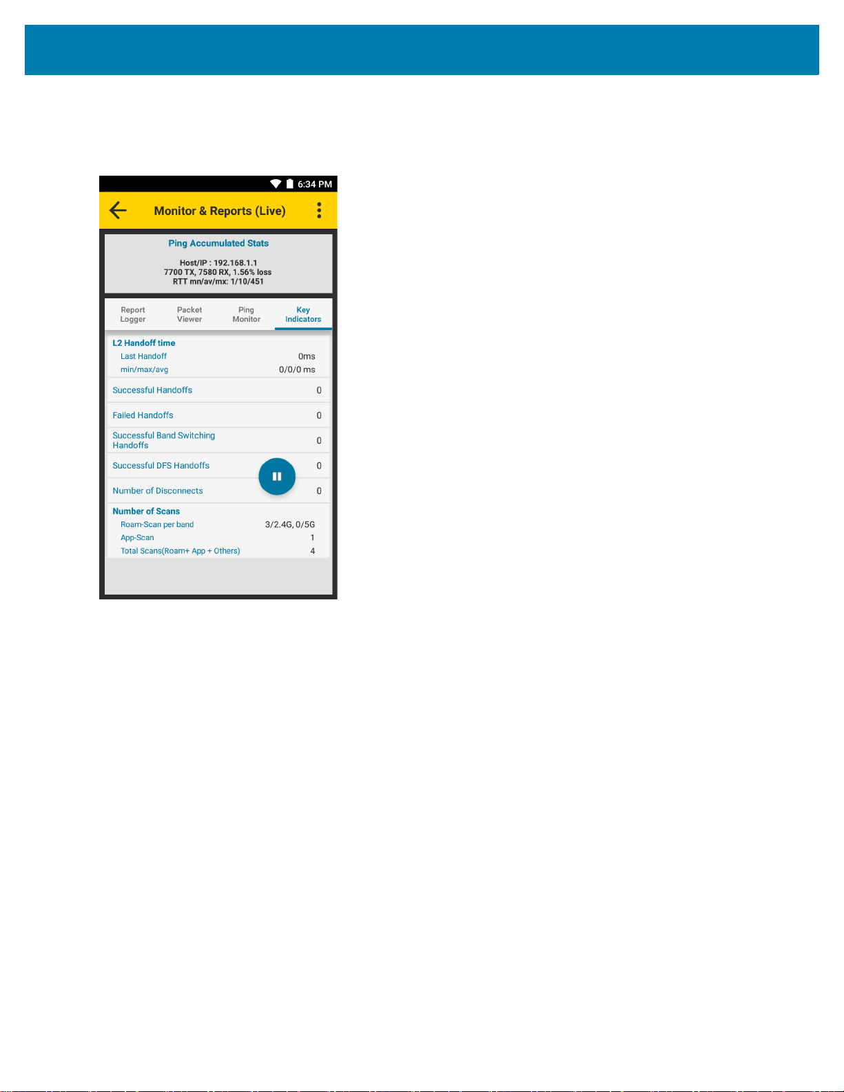
• Key Indicators - Displays a summary of handoffs, disconnects, and the number of scans accumulated
during a live session. When a live session is not running, a final summary displays.
Figure 20 Key Indicators
29

Using SmartMU
View Options
If Roaming Analysis is running, touch to pause live monitoring. Touch to display view options.
Figure 21 View Options
• Resume Live Events - Touch to resume live monitoring.
• Load session - Touch to load a previous session.
• Goto position - Use slider and buttons to quickly navigate through long lists of data. Not available in the
Key Indicators tab.
Ping Refresh Settings
Use Ping Refresh Settings to change the time interval between pings (range: 2 - 20 seconds, default: 5 seconds).
Figure 22 Ping Refresh Settings
30

Using SmartMU
To change the time interval between pings:
1. Touch > Roaming Analysis > Monitor & Reports > > Ping Refresh Settings.
2. Use the slider to set the interval.
3. Touch OK.
31
Voice Analysis
Use Voice Analysis to troubleshoot or monitor simulated voice traffic performance, and get analysis reasons in
real-time for connectivity and link quality issues. The analysis data includes reports, packets, traffic statistics, and
performance indicators. Analysis is available for open, PSK, and 11r/FT networks.
Voice Analysis runs continuously during a live session, with active voice stream traffic simulated using specialized
ping packets with specific spacing, formatting, and payload. It is not recommended to run a live session for more
than several hours. If a session of an hour or more is required, create multiple sessions by stopping and restarting
the analysis at planned intervals.
When actively using a voice application while running Voice Analysis, all voice traffic is run in parallel. SmartMU
does not provide an option to disable the simulated traffic of the Voice Analysis feature. However, the load of any
combined parallel traffic does not impact the device processing itself.
In some cases the additional SmartMU traffic creates desirable network stress, which assists in analyzing the
impact on the voice application call.
In cases where isolating the voice application stream is critical, use Roaming Analysis and select > Roaming
Analysis > Settings > Advance Methods > Do not generate ping traffic.
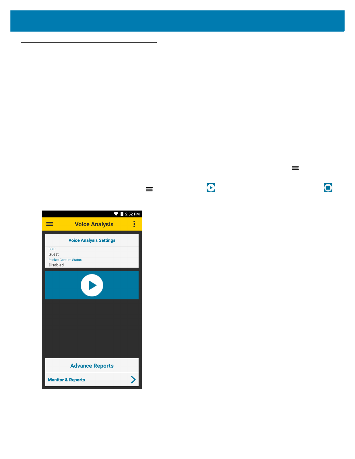
To start a Voice Analysis session, touch > Voice Analysis > . To stop a Voice Analysis sessions, touch .
Using SmartMU
Figure 23 Voice Analysis
Voice Analysis Settings
The main screen displays the current settings:
32

Using SmartMU
• SSID - VoIP network the device is connected to
• Packet Capture Status - Packet capture status (default - Disabled).
To change the Voice Analysis settings, touch > Voice Analysis > > Settings.
To ensure that the changes to the Voice Analysis settings take effect, touch .
Figure 24 Voice Analysis Settings
• Profile Settings
• Current Status - Dsplays the current SSID status.
• Current Selection - Touch to select from a list of available SSIDs. When not connected to a VoIP
network, this selection is required.
• Session Name - Touch to enter a session name. For information on how to clear or save sessions, see
Save Data Options on page 34.
• Advance Settings
• Set Remote Server - To manually set the IP or URL for the remote server, slide the switch for Use
Gateway IP of SSID Network to the OFF position.
• Packets Viewer - Select a packet category (default: WLAN Mgmt + Selective Data Packets).
• Analysis Report Level - Not supported.
Enable/Disable pcap capture - Not supported.
• Low Storage Options - Select an option for managing data when available storage is less than 15%.
• Scan data for ‘Scan List’ and ‘Coverage View’ features, based on - Select the scan data type to use for
Scan List and Coverage View features while Roaming Analysis is running (default: Only Roam Scans).
33

Using SmartMU
Save Data Options
Use Save Data Options to clear or export Voice Analysis data.
Figure 25 Saved Data Options
Clear Sessions
To clear all Voice Analysis session data:
1. Touch > Voice Analysis > > Save Data Options.
2. Select individual sessions to clear, or touch Select All to clear all sessions.
3. Touch OK.
Export Saved Data
Export session data to text files containing JSON objects. The SmartMU application saves the files to the smu
folder.
To export all saved Voice Analysis session data:
1. Touch > Voice Analysis > > Save Data Options.
2. Select individual sessions to export, or touch Select All to export all sessions.
3. Touch OK. Text files containing JSON objects are created for each tab in Voice Analysis > Monitor &
Reports.
To view exported files, ensure Voice Analysis and logging are not running, connect the device to a host
computer using a USB cable, and copy the files from the device to the host computer.
34

Using SmartMU
Advance Reports
While Voice Analysis is running, session data displays in real time. When Voice Analysis is not running, the most
recent report displays. To load a previous session while the live session runs in the background or when Voice
Analysis is not running. See View Options on page 40.
Monitor and Reports
To view Voice Analysis reports, touch > Voice Analysis > Monitor & Reports.
NOTE: Each time Voice Analysis starts, SmartMU intentionally causes the device to disconnect and then
reconnect to the network. For this reason, the first Disconnected error in the Report Logger tab can be ignored.
Figure 26 Monitor and Reports
• Ping Accumulated Stats - Displays ping data indicators, accumulated in real-time during a live session,
or a final summary of a loaded session.
35

Using SmartMU
• Report Logger - Displays connectivity and Voice Analysis results. Touch a row to display detailed
parameters and reasons of performance thresholds and issues. See Report Logger Content on page 50.
Rows containing a warning message display the Warning Details button. Touch Warning Details to
display one or more sub-reports.
Figure 27 Sub-Reports
36

Using SmartMU
• Packet Viewer - Displays the time, direction, and type of select packets in a session. Touch a packet to
view certain fields from its header content. Packet details include 802.11 authentication and association,
DHCP, and ARP.
Raw analyzed packets are available after an analysis session, with packet capture enabled, ends. See
Voice Analysis Settings on page 32.
Figure 28 Packet Viewer
37

Using SmartMU
• Ping Monitor - Displays detailed ping statistics.
When specific ping errors are detected, such as 100 percent packet loss, or when three or more
consecutive packets are lost during ping, touch the information row to view an error report.
Figure 29 Ping Monitor
38

Using SmartMU
• Key Indicators - Displays a summary of handoffs, disconnects, the number of scans, and additional voice
traffic events accumulated during a live session. When a live session is not running, a final summary
displays.
Figure 30 Key Indicators
39

Using SmartMU
View Options
If Voice Analysis is running, touch to pause live monitoring. Touch to display view options.
Figure 31 View Options
• Resume Live Events - Touch to resume live monitoring.
• Load session - Touch to load a previous session.
• Goto position - Use slider and buttons to quickly navigate through long lists of data. Not available in the
Key Indicators tab.
40

Networking Tools
To view available networking tools, touch > Networking Tools.
Ping
Ping is a self-contained utility that sends an ICMP ping with configurable input settings. Configure and run up to
two separate pings at the same time, each with a different IP or URL address.
Use Ping to determine reachability and to perform a self-contained test of end to end traffic performance.
It is not recommended to use Ping while Voice Analysis is running. To use Ping while Roaming Analysis is running,
select > Roaming Analysis > > Settings > Advance Settings > Advance Methods > Do not generate
ping traffic.
To use Ping, touch > Networking Tools > Ping.
Figure 32 Ping Screen
Using SmartMU
41

Using SmartMU
Ping Settings
Ping Settings provides options for configuring ping input settings. To configure ping input settings, touch .
Figure 33 Ping Settings
• Continuous ping - Enable or disable continuous ping (default: disabled)
• Count - Number of ping requests to send (default: 10). This option is not available when using continuous
ping.
• Interval (ms) - Amount of time in ms between ping requests (default: 1000)
• Timeout (ms) - Amount of time in ms before a ping times out (default: 500)
• Max TTL - Maximum time to live for a packet (default: 64)
• Packet Size - Size of each ping packet in bytes (default: 64)
• TOS (Hex Value) - Type of service as a hexadecimal value (default: 00 Best Effort).
42
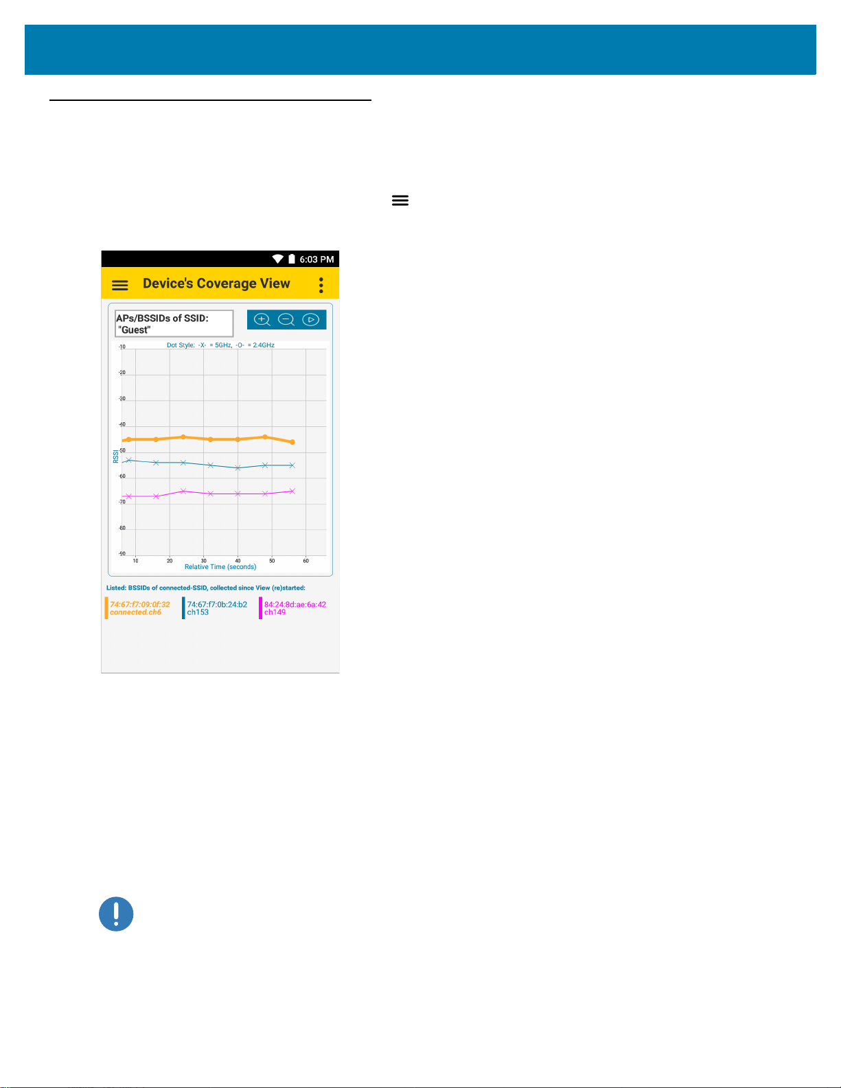
Device’s Coverage View
Device’s Coverage View displays the live RSSI values of BSSIDs of the connected SSID versus relative time (in
seconds), with connectivity events
To display the Device’s Coverage View, touch > Device’s Coverage View.
Figure 34 Device’s Coverage View
Using SmartMU
Each line is a connected BSSID with dots marking the RSSI values from scan samples.
The legend at the bottom of the screen matches each BSSID to a color and specifies the currently connected
BSSID. The BSSID colors also display as vertical bars on the Scan List screen.
Vertical dotted lines designate events which can happen outside of regular scan intervals:
• VIEW (RE)STARTED – View started without a Connectivity or Roam event involved
• ROAMED – AP hand-off event
• DISCONN – Disconnection from SSID
• NEW CONN – Connection to SSID.
IMPORTANT By default, when the Roaming Analysis or Voice Analysis feature is running in the background, the
Device’s Coverage View only displays
scanning and roaming logics. RSSI values do not display in fixed scan interval spacing. To change the
default setting, see
Roaming Analysis Settings on page 23 or Voice Analysis Settings on page 32.
RSSI values when available from the device's internal
43

Figure 35 Device’s Coverage View Events
Using SmartMU
To zoom in and out, place two fingers on the screen and pinch them together (to zoom out) or spread them apart
(to zoom in), or touch the and icons. Pan in any direction inside the graph by moving a finger on the screen.
Using Zoom or Pan pauses auto-scroll. Touch the icon to enable auto-scroll. Values continue to update even if
not in viewing area.
Auto Reachability Test
Use the Auto Reachability Test to automatically send a batch of four ICMP packets to the Gateway IP address a
couple of seconds after each CONN or ROAMED event. The result displays on the Device’s Coverage View
screen next to the CONN or ROAMED event.
Touch > Auto Reachability Test and use the toggle button to enable or disable this test.
44

Logging
Using SmartMU
NOTE: Not Supported.
45

Using SmartMU
Fusion Advanced Configuration
NOTE: Only available in SmartMU Lite. See SmartMU Mode Selection on page 49.
Use the Fusion Advanced Configuration screen to view or edit the parameters for power save mode or band
preference. A password is required to edit the parameters.
• In SmartMU Lite, use the default password ?gUpD!8(.
Figure 36 Fusion Advanced Config Screen
After entering the password, the following options are available:
• Power Save Mode
• Active (CAM)
• WMM-PS
• Null Data PS (NDP) (default)
• PS Poll.
• Band Preference
• Disable (default)
• Prefer 2.4 GHz
• Prefer 5 GHz.
46

About
Use About to view the application version number for each layer of the SmartMU application.
Figure 37 About Screen
Using SmartMU
47

Camera Preview
When Camera Preview is enabled, a live camera view appears on the screen and remains active while SmartMU is
open.
Figure 38 Camera Preview
Using SmartMU
To enable the Camera Preview feature from any screen in SmartMU, touch > Camera Preview. To disable,
touch > Camera Preview or touch the X on the top right of the camera view. To move the camera view box,
touch and drag anywhere on the screen.
Use Camera Preview to document the location of APs or diagnose issues, such as physical obstructions with low
RSSI or poor coverage, by capturing a screenshot. To capture a screenshot, simultaneously press and hold the
power key and the volume down key. This saves the entire screen, including the SmartMU application and camera
preview to the device storage as a PNG file.
48

SmartMU Mode Selection
Use SmartMU Mode Selection to toggle between the full version of SmartMU and SmartMU Lite. SmartMU Lite
uses the standard Android API and is useful for diagnosing devices that do not support the full version of SmartMU.
The following features are limited or not available in SmartMU Lite:
• Scan List - limited content
• Connection Analysis - not available
• Roaming Analysis - not available
• Voice Analysis - not available
• Logging - not available.
To enable or disable SmartMU Lite mode from any screen in SmartMU:
1. Touch > SmartMU Lite on/off.
2. Touch the switch to enable or disable SmartMU Lite.
3. Touch OK.
Using SmartMU
49

Report Logger Content
Introduction
This chapter provides detailed information about the Report Logger tab of the Roaming Analysis and Voice
Analysis features.
To view Roaming Analysis reports, touch > Roaming Analysis > Monitor & Reports > Report Logger.
To view Voice Analysis reports, touch > Voice Analysis > Monitor & Reports > Report Logger.
Content Structure
Events found in the Report Logger tab are structured in the following order:
• Header
• Parameters
• Reasons
Header
The header contains the severity class (INFO, WARNING, ERROR), the time the event occurred, and a short
description. In the default view, only the header is visible. Touch a header for an expanded view that lists
parameters and reasons, when applicable.
Roaming and Voice Analysis Headers
INFO Severity Class Headers
• Roam Analysis Started
• Roam Analysis Stopped
• AUTH Started (802.11 Auth)
• AUTH Completed (802.11 Auth)
• ASSOC Started (802.11 Assoc)
• ASSOC Completed (802.11 Assoc)
• EAPOL STARTED
50

Report Logger Content
• EAPOL Completed
• DHCP Started
• DHCP Completed
• ARP Started
• ARP Completed
• Connection Completed (Full connection attempt completed)
• Roam Started
• Reassoc Completed (802.11 Reassoc)
• Roam Completed
• Scan Started
• Scan Completed
• Device storage space reached 60%
• Disconnect Suppression Triggered
• Disconnect Suppression Completed.
WARNING or ERROR Severity Class Headers
• Connection Failed (Full connection attempt failed)
• Roam Failed (Roam attempt failed)
• Authentication Failed (802.11 Auth attempt failed)
• Association Failed (802.11 Assoc attempt failed)
• EAPOL Failed (EAPOL handshake attempt failed)
• DHCP Failed (DHCP attempt failed)
• ARP Failed (ARP attempt failed)
• Disconnected (Fully Disconnected from Wifi)
• Device storage space reached 70%
• Device storage space reached 80%
• Device storage space reached 90%
• Roam Retry
• Frequent Roams Seen.
Voice Analysis Only Headers
INFO or WARNING Severity Class Headers
• Voice Analysis Started
• Voice Analysis Stopped
• Voice Consolidated Report.
Parameters
Standard Wi-Fi parameters are located directly under the header when applicable.
51

Report Logger Content
Reasons
Analyzed reasons are provided for the WARNING and ERROR severity classes when applicable.
Roaming and Voice Analysis Reasons
Analyzed Reason Strings
• Timeout happened between substate machines
For example: Auth response came, but Assoc request was not sent
• Packet State machine Succeeded but Framework did not notify the state change
• Packet State machine Success but Framework notified wrong state change
• Analysis could not start due to MAC Analysis Failed
• Analysis could not start due to EAPOL Analysis Failed
• Analysis could not start due to DHCP Analysis Failed
• Analysis could not start due to ARP Analysis Failed
• Keynonce of eapol1 and eapol3 not equal
• ReplayCounter of eapol1 not equal to eapol2 or eapol3 is not equal to (eapol1 + 1)
• DHCP_INVALID
• DHCP_DECLINE
• DHCP_NAK
• DHCP_RELEASE
• NO DHCP server(s) found
• DHCP server didn't respond to the request
• Device failed to start discover after NAK
• AP of selected SSID to analyse is not in vicinity
• EAPOL four way handshake timeout
• Analysis is been done on an Open/WEP Profile Hence EAPOL is not applicable
• Authentication has Timedout
• Association has Timedout
• WiFi is turn off
• Unable to reach the destination address
• Destination address was reachable But Reachability is poor
• Destination address was reachable But Reachability is only 50%
• Destination address was reachable But Reachability is 75%
• Destination address was reachable Reachability is 100%
• Success
• Unable to reach gateway through arp
• Gateway IP is not available to test arp reachability
• Association not started
• EAPOL Key 1 not started
52

Report Logger Content
• DHCP not started
• ARP not started
• EAPOL Key 2 not sent
• EAPOL Key 3 not received
• EAPOL Key 4 not sent
• DHCP Request not started
• Ping test not started
• Undefined Error
• Device Roamed from Non Preferred Band to Preferred Band AP
• Device Roamed to Non Preferred Band
• Device failed to Roam to Good Signal Strength Access Points are seen in Preferred Band
• Device failed to Roam to Preferred Band after Roam Scan
• Roam Candidate AP's RSSI is greater than Previous AP's RSSI
• Delta RSSI of Candidate AP's and Previous AP is not greater than 5 dbms
• Candidate AP is not the Best AP in the Scan List
• Candidate AP is also not the Second Best AP in the Scan List
• Gradual Roam. Current and previous RSSI average difference is 0-5 dbm
• Sporadic Roam. Current and previous RSSI average difference is greater than 5 dbm
• Roam due to connected SSID packet not found in scan cache
• Extreme Roam. Instant RSSI and current RSSI average difference is greater than 6 dbm
• Roam due to Very Weak AP Signal. Less than -85 dbm
• No Access Points are seen in Preferred Band
• Low Signal Strength Access Points are seen in Preferred Band
• Unknown Scenario
• Disconnect Reason Unknown
• Disconnect Reason - Screen OFF
• Disconnect Reason - WiFi Disabling
• Disconnect Reason - WiFi Disabled
• Disconnect Reason - New Profile Added in UI
• Disconnect Reason - Profile Updated in UI
• Disconnect Reason - Profile Deleted in UI
• Disconnect Reason - Deauth Packet from AP
• Disconnect Reason - Profile Roam from UI
• Disconnect Reason - Deauth packet from Driver
• Low Signal Strength.(condition: formula made of RSSI, TX Loss , RX Loss)
• High Interference.(condition: formula made of SNR, TX Loss , RX Loss)
• High Channel Load.(condition: formula made of AP's IE load, TX Loss , RX Loss)
• Poor Coverage Area.(condition: scan yields weaker than -65 dBm 'best' coverage)
• Tx Power and Data Rate Mismatch.
53

Report Logger Content
Standard IEEE Codes for De-Authentication Packets
When the device receives a de-authentication packet from the AP, the analyzed reason strings may include an
IEEE 802.11 standard reason code. The reason code is retrieved directly from the 802.11 packet. The reason code
value, located in the expanded view, is prefixed with
To view the meanings of de-authentication code values, refer to the reason codes table, found in the IEEE 802.11
standard.
DEAUTH CODE.
Voice Analysis Only Reasons
WARNING Severity Class Headers
Rows containing a warning message display the Warning Details button. Touch Warning Details to display one
or more sub-reports.
Each sub-report contains one of the following parameters:
• CONSECUTIVE PACKET LOSS type - More than 3 packets lost consecutively within a sub-window
• PACKET LOSS EXCEEDED type - More than 20% packets lost within a sub-window
• LATENCY EXCEEDED type - Latency yielded value larger than 200ms
• JITTER EXCEEDED type - Jitter yielded value larger than 100ms.
The CONSECUTIVE PACKET LOSS and PACKET LOSS EXCEEDED parameters may also provide one of the
follow analyzed reasons:
• Packet Loss during Power Save
• Packet Loss during Roam Scan
• Packet Loss during Low Signal Strength
• Packet Loss during High Interference
• Packet Loss during High Channel Load
• Packet Loss in Poor Coverage Area
• Packet Loss - Loss condition happened with none of the above situations.
54

www.zebra.com
 Loading...