


MC33XX
Mobile Computer
Integrator Guide
for Android ™ 8.1 Oreo
MN-003229-06EN Rev A

Copyright
ZEBRA and the stylized Zebra head are trademarks of Zebra Technologies Corporation, registered in many
jurisdictions worldwide. Google, Android, Google Play and other marks are trademarks of Google LLC; Oreo is a
trademark of Mondelez International, Inc. group. All other trademarks are the property of their respective owners.
©2020 Zebra Technologies Corporation and/or its affiliates. All rights reserved.
COPYRIGHTS & TRADEMARKS: For complete copyright and trademark information, go to www.zebra.com/
copyright.
WARRANTY: For complete warranty information, go to www.zebra.com/warranty
END USER LICENSE AGREEMENT: For complete EULA information, go to www.zebra.com/eula
Terms of Use
• Proprietary Statement
This manual contains proprietary information of Zebra Technologies Corporation and its subsidiaries (“Zebra
Technologies”). It is intended solely for the information and use of parties operating and maintaining the
equipment described herein. Such proprietary information may not be used, reproduced, or disclosed to any
other parties for any other purpose without the express, written permission of Zebra Technologies.
• Product Improvements
Continuous improvement of products is a policy of Zebra Technologies. All specifications and designs are
subject to change without notice.
• Liability Disclaimer
Zebra Technologies takes steps to ensure that its published Engineering specifications and manuals are
correct; however, errors do occur. Zebra Technologies reserves the right to correct any such errors and
disclaims liability resulting therefrom.
• Limitation of Liability
In no event shall Zebra Technologies or anyone else involved in the creation, production, or delivery of the
accompanying product (including hardware and software) be liable for any damages whatsoever (including,
without limitation, consequential damages including loss of business profits, business interruption, or loss of
business information) arising out of the use of, the results of use of, or inability to use such product, even if
Zebra Technologies has been advised of the possibility of such damages. Some jurisdictions do not allow the
exclusion or limitation of incidental or consequential damages, so the above limitation or exclusion may not
apply to you.
.
.
Revision History
Changes to the original guide are listed below:
Change Date Description
-01 Rev A 12/2018 Initial release.
-02 Rev A 04/2019 Updated the DataWedge chapter to remove Imager as Camera and updated the
-03 Rev A 09/2019 Updated to indicate the lanyard is compatible only with the MC33XX-R and
Accessories chapter note to indicate that to function properly, remove the entire
rubber boot from the device before placing the device in a charging cradle.
MC33XX-S configurations, remove screws on the forklift mount, and remove
reference to vibration.
2

Change Date Description
-04 Rev A 04/2020 Updated to include the SE4770 2D Imager.
-05 Rev A 09/2020 Correct
-06 Rev A 03/2022 Updated the weight of 5-Slot Charge Only Cradle and 5-Slot Charge Only Cradle.
Updated to include pressing and holding the Right Scan key (MC33XX-S/R) or the
trigger (MC33XX-G) to enter system recovery mode.
100 mil Code 39 (paper) in the
SE4850-ER Decode Zone table.
3

Table of Contents
Copyright ......................................................................................................................... 2
Terms of Use ..................................................................................................................2
Revision History ..............................................................................................................2
About This Guide........................................................................................................ 12
Introduction ................................................................................................................... 12
Configurations ............................................................................................................... 12
Software Versions ......................................................................................................... 15
Chapter Descriptions .................................................................................................... 15
Notational Conventions ................................................................................................. 16
Related Documents and Software ................................................................................ 16
Service Information ....................................................................................................... 16
Provide Documentation Feedback ................................................................................ 17
Getting Started............................................................................................................ 18
Introduction ................................................................................................................... 18
Setup ............................................................................................................................. 18
Installing a microSD Card ...................................................................................... 18
Installing the MC33XX-G Battery .......................................................................... 20
Installing the MC33XX–R/S Battery ....................................................................... 21
Charging the Battery ............................................................................................. 22
Google Account Setup .......................................................................................... 24
Zebra Visibility Services ........................................................................................ 25
Resetting the Device ..................................................................................................... 25
Performing a Soft Reset ........................................................................................ 25
Performing a Hard Reset ....................................................................................... 25
Accessories................................................................................................................. 27
Introduction ................................................................................................................... 27
4

Table of Contents
MC33XX Accessories ................................................................................................... 27
Compatibility .................................................................................................................31
Battery Comparison ............................................................................................... 32
Battery Compatibility ............................................................................................. 32
1-Slot USB Charge Cradle ............................................................................................ 32
Charging the MC33XX Battery .............................................................................. 33
Charging an MC33XX Spare Battery .................................................................... 34
Battery Charging in 1- Slot USB Charge Cradle ................................................... 35
5-Slot Charge Only ShareCradle .................................................................................. 36
Charging the MC33XX Battery .............................................................................. 37
Battery Charging in the 5-Slot Charge Only ShareCradle ..................................... 37
5-Slot Ethernet ShareCradle ......................................................................................... 38
Charging the MC33XX Battery .............................................................................. 39
Battery Charging in the 5-Slot Ethernet ShareCradle ........................................... 39
Daisy-chaining Ethernet ShareCradles ................................................................. 39
Establishing Ethernet Connection ......................................................................... 42
LED Indicators ....................................................................................................... 42
5-Slot ShareCradle with 4-Slot Battery Charger ........................................................... 43
Charging the MC33XX Battery .............................................................................. 44
Charging Spare Batteries ...................................................................................... 44
Battery Charging in the 5-Slot ShareCradle with 4-Slot Battery Charger .............. 44
5-Slot Ethernet ShareCradle with 4-Slot Battery Charger ............................................. 44
Charging the MC33XX Battery .............................................................................. 45
Charging Spare Batteries ...................................................................................... 46
Battery Charging in the 5-Slot Ethernet ShareCradle with 4-Slot Battery Charger 46
Daisy-chaining Ethernet Cradles ........................................................................... 46
Establishing Ethernet Connection ......................................................................... 49
LED Indicators ....................................................................................................... 49
4-Slot Spare Battery Charger ........................................................................................ 50
Charging Spare Batteries ...................................................................................... 50
Battery Charging ................................................................................................... 51
20-Slot Spare Battery Charger ...................................................................................... 52
Charging Spare Batteries ...................................................................................... 52
Battery Charging ................................................................................................... 53
USB Charge Cable ....................................................................................................... 54
Connecting the USB Charge Cable to Device ....................................................... 55
Connecting the USB Charge Cable to Host Computer ......................................... 55
Charging the Device .............................................................................................. 56
Disconnecting the USB Charge Cable .................................................................. 57
MC33XX Charge Only Adapter ..................................................................................... 58
Adapter Installation ................................................................................................ 58
5

Table of Contents
MC33XX-G Rubber Boot .............................................................................................. 60
MC33XX-R Rubber Boot ............................................................................................... 61
MC33XX-S Rubber Boot ............................................................................................... 63
Rigid Holster .................................................................................................................63
MC33XX-G Fabric Holster ............................................................................................ 65
Belt Strap ............................................................................................................... 65
Shoulder Strap ...................................................................................................... 66
Using the Belt Strap .............................................................................................. 67
Using the Shoulder Strap ...................................................................................... 68
MC33XX-R/S Fabric Holster ......................................................................................... 69
Belt Clip ................................................................................................................. 69
Shoulder Strap ...................................................................................................... 70
Using the Belt Clip ................................................................................................. 70
Using the Shoulder Strap ...................................................................................... 72
Un-powered Forklift Mount ............................................................................................ 73
Installation ............................................................................................................. 74
Replacement Hand Strap for MC33XX-G ..................................................................... 75
Replacement Hand Strap for MC33XX-R/S .................................................................. 76
Lanyard ......................................................................................................................... 78
Install Lanyard on MC33XX ................................................................................... 79
Using the Cross-body Strap .................................................................................. 80
Using the Belt Clip ................................................................................................. 81
Charging the MC33XX with the Lanyard ............................................................... 82
USB Communication .................................................................................................. 83
Introduction ................................................................................................................... 83
Transferring Files with a Host Computer via USB ........................................................ 83
Transferring Files .......................................................................................................... 83
Transferring Photos ...................................................................................................... 84
Disconnect from the Host Computer ............................................................................. 84
DataWedge .................................................................................................................. 85
Introduction ................................................................................................................... 85
Accessing DataWedge .................................................................................................. 85
Basic Scanning ............................................................................................................. 85
Barcode Capture with Imager ................................................................................ 85
Barcode Capture with Laser Scanner ................................................................... 86
Profiles .......................................................................................................................... 86
Profile0 .......................................................................................................................... 87
Plug-ins ......................................................................................................................... 87
6

Table of Contents
Input Plug-ins ........................................................................................................ 87
Process Plug-ins ................................................................................................... 87
Output Plug-ins ...................................................................................................... 88
Profiles Screen .............................................................................................................. 88
Profile Context Menu .................................................................................................... 89
Options Menu ........................................................................................................ 89
Disabling DataWedge ............................................................................................ 89
Creating a New Profile .................................................................................................. 89
Profile Configuration ..................................................................................................... 90
Associating Applications ........................................................................................ 91
Data Capture Plus ................................................................................................. 93
Barcode Input ................................................................................................................ 94
Voice Input .......................................................................................................... 110
Keystroke Output ................................................................................................. 111
Intent Output ........................................................................................................ 112
IP Output ............................................................................................................. 114
Using IP Output with IPWedge ............................................................................ 115
Configuring ADF Plug-in ...................................................................................... 118
Creating a Rule ................................................................................................... 118
DataWedge Settings ................................................................................................... 126
Importing a Configuration File ............................................................................. 127
Importing a Profile File ........................................................................................ 127
Exporting a Profile ............................................................................................... 128
Restoring DataWedge ......................................................................................... 128
Configuration and Profile File Management ................................................................ 128
Auto Import .......................................................................................................... 129
Reporting ............................................................................................................. 129
Programming Notes ............................................................................................ 129
Overriding Trigger Key in an Application ............................................................. 129
Capture Data and Taking a Photo in the Same Application ................................ 129
Disable DataWedge on Device and Mass Deploy ............................................... 130
DataWedge APIs ................................................................................................. 130
Soft Scan Trigger ................................................................................................ 130
Function Prototype .............................................................................................. 130
Scanner Input Plugin ........................................................................................... 131
Enumerate Scanners ........................................................................................... 132
Set Default Profile ............................................................................................... 135
Reset Default Profile ........................................................................................... 136
Switch To Profile ................................................................................................. 138
Settings...................................................................................................................... 141
7

Table of Contents
Introduction ................................................................................................................. 141
WLAN Configuration ................................................................................................... 141
Configuring a Secure Wi-Fi Network ................................................................... 141
Manually Adding a Wi-Fi Network ....................................................................... 142
Configuring for a Proxy Server ............................................................................ 143
Configuring the Device to Use a Static IP Address ............................................. 144
Advanced Wi-Fi Settings ..................................................................................... 145
Additional Wi-Fi Settings ..................................................................................... 146
Setting Screen Lock .................................................................................................... 147
Setting Screen Lock Using PIN ........................................................................... 148
Setting Screen Unlock Using Password .............................................................. 148
Setting Screen Unlock Using Pattern .................................................................. 149
Showing Passwords ............................................................................................ 150
Remapping a Button ................................................................................................... 150
Remappable Keys ....................................................................................................... 151
UI Listed Keys ..................................................................................................... 151
Other Remappable Keys ..................................................................................... 151
Non-Remappable Keys ....................................................................................... 152
Accounts ..................................................................................................................... 152
Language Usage ......................................................................................................... 152
Changing the Language Setting .......................................................................... 152
Adding Words to the Dictionary ........................................................................... 153
Keyboard Settings ............................................................................................... 153
PTT Express Configuration ......................................................................................... 153
RxLogger .................................................................................................................... 153
RxLogger Settings ............................................................................................... 154
RxLogger Configuration ...................................................................................... 154
Logcat Module ..................................................................................................... 156
Configuration File ................................................................................................ 159
Enabling Logging ................................................................................................. 159
Disabling Logging ................................................................................................ 159
Extracting Log Files ............................................................................................. 160
RxLogger Utility .......................................................................................................... 161
App View ............................................................................................................. 161
Backup ................................................................................................................ 163
About Phone ............................................................................................................... 166
Application Deployment........................................................................................... 167
Introduction ................................................................................................................. 167
Security ....................................................................................................................... 167
Secure Certificates ...................................................................................................... 167
8

Table of Contents
Installing a Secure Certificate ..................................................................................... 167
Configuring Credential Storage Settings ............................................................. 168
License Manager ........................................................................................................ 168
Android Versions Supported ............................................................................... 169
Requirements ...................................................................................................... 169
Start Application .................................................................................................. 169
Activate License .................................................................................................. 170
Add License Source ............................................................................................ 173
Refresh a License ............................................................................................... 174
Settings ............................................................................................................... 174
Development Tools ..................................................................................................... 178
Android ................................................................................................................ 178
EMDK for Android ............................................................................................... 179
StageNow ............................................................................................................ 179
ADB USB Setup .......................................................................................................... 179
Enabling USB Debugging ........................................................................................... 179
Application Installation ................................................................................................ 180
Installing Applications Using the USB Connection .............................................. 180
Installing Applications Using the Android Debug Bridge ..................................... 182
Installing Applications Using a microSD Card ..................................................... 183
Uninstalling an Application .................................................................................. 184
Performing a System Update ...................................................................................... 185
Downloading the System Update Package ......................................................... 185
Using microSD Card ............................................................................................ 185
Using ADB ........................................................................................................... 186
Verify System Update Installation ....................................................................... 187
Performing an Enterprise Reset .................................................................................. 187
Downloading the Enterprise Reset Package ....................................................... 187
Using microSD Card ............................................................................................ 187
Using ADB ........................................................................................................... 188
Performing a Factory Reset ........................................................................................ 189
Downloading the Factory Reset Package ........................................................... 189
Using microSD Card ............................................................................................ 189
Using ADB ........................................................................................................... 189
Storage .......................................................................................................................190
Random Access Memory .................................................................................... 190
Internal Storage ................................................................................................... 191
External Storage .................................................................................................. 192
Enterprise Folder ................................................................................................. 196
App Management ........................................................................................................ 196
Viewing App Details ............................................................................................ 197
9

Table of Contents
Managing Downloads ................................................................................................. 197
Maintenance and Troubleshooting ......................................................................... 199
Introduction ................................................................................................................. 199
Maintaining the Device ................................................................................................ 199
Battery Safety Guidelines ........................................................................................... 200
Cleaning Instructions .................................................................................................. 200
Approved Cleanser Active Ingredients ............................................................... 200
Harmful Ingredients ............................................................................................. 201
Device Cleaning Instructions ............................................................................... 201
Special Cleaning Notes ....................................................................................... 201
Cleaning Materials Required ............................................................................... 201
Cleaning Frequency ............................................................................................ 202
Cleaning the Device ............................................................................................ 202
Cleaning Battery Connectors .............................................................................. 202
Cleaning Cradle Connectors ............................................................................... 202
Troubleshooting SmartMU .......................................................................................... 203
Troubleshooting .......................................................................................................... 203
Troubleshooting the MC33XX ............................................................................. 203
1-Slot USB Charge Cradle Troubleshooting ....................................................... 205
5-Slot Charge Only ShareCradle Troubleshooting .............................................. 206
5-Slot Ethernet ShareCradle Troubleshooting .................................................... 207
5-Slot ShareCradle with 4-Slot Battery Charger Troubleshooting ....................... 207
5-Slot Ethernet ShareCradle with 4-Slot Battery Charger Troubleshooting ........ 208
4-Slot Spare Battery Charger Troubleshooting ................................................... 209
20-Slot Spare Battery Charger Troubleshooting ................................................. 209
USB Charge Cable .............................................................................................. 210
Specifications............................................................................................................ 211
Introduction ................................................................................................................. 211
MC33XX Technical Specifications .............................................................................. 211
SE965 Decode Zone ........................................................................................... 215
SE4750-SR Decode Zone ................................................................................... 216
SE4770-SR Decode Zones ................................................................................. 217
SE4850-ER Decode Zone ................................................................................... 217
MC33XX Accessory Specifications ............................................................................. 219
1-Slot USB Charge Cradle with Spare Battery Charger Technical Specifications 219
5-Slot Charge Only ShareCradle Technical Specifications ................................. 219
5-Slot Ethernet ShareCradle Technical Specifications ........................................ 220
5-Slot Charge ShareCradle with 4-Slot Battery Charger Technical Specifications 220
10

Table of Contents
5-Slot Ethernet ShareCradle with 4-Slot Battery Charger Technical Specifications 221
4-Slot Spare Battery Charger Technical Specifications ...................................... 222
20-Slot Spare Battery Charger Technical Specifications .................................... 222
USB Charge Cable Technical Specifications ...................................................... 223
Keypad Remap Strings............................................................................................. 224
Keypad Remap Strings ............................................................................................... 224
Index
11

About This Guide
Introduction
This guide provides information about using the MC33XX mobile computers and accessories.
NOTE: Screens and windows pictured in this guide are samples and can differ from actual screens.
Configurations
MC33XX used in this guide refers to all configurations, except where noted. MC33XX-G refers to the
Trigger configuration. MC33XX-R refers to the Rotate configuration. MC33XX-S refers to the Straight
configuration. MC33XX-S45 refers to the 45 degree angle Straight configuration.
12

This guide covers the following configurations:
Table 1 Configurations
About This Guide
Configuration Radios Display Memory
MC33XX–G
Standard
WLAN: IEEE
®
802.11a/b/g/n/ac/d
4.0” color 2 GB RAM /
16 GB Flash
/h/i/k/r/w
WPAN: Bluetooth
V4.1, V2.1 + EDR
w/ Bluetooth Low
Energy (BLE)
MC33XX–G
Premium
WLAN: IEEE
802.11a/b/g/n/ac/d
®
4.0” color 4 GB RAM /
16 GB Flash
/h/i/k/r/w
WPAN: Bluetooth
V4.1, V2.1 + EDR
w/ Bluetooth Low
Energy (BLE)
NFC
MC33XX–G
Premium +
WLAN: IEEE
802.11a/b/g/n/ac/d
®
4.0” color 4 GB RAM /
32 GB Flash
/h/i/k/r/w
WPAN: Bluetooth
V4.1, V2.1 + EDR
w/ Bluetooth Low
Energy (BLE)
NFC
MC33XX–R
Standard
WLAN: IEEE
802.11a/b/g/n/ac/d
®
4.0” color 2 GB RAM /
16 GB Flash
/h/i/k/r/w
WPAN: Bluetooth
V4.1, V2.1 + EDR
w/ Bluetooth Low
Energy (BLE)
MC33XX–R
Premium
WLAN: IEEE
802.11a/b/g/n/ac/d
®
4.0” color 4 GB RAM /
16 GB Flash
/h/i/k/r/w
WPAN: Bluetooth
V4.1, V2.1 + EDR
w/ Bluetooth Low
Energy (BLE)
NFC
Data Capture
Options
SE965 1D,
SE4750-SR 2D,
Operating
System
Android-based
AOSP/GMS 8.1
SE4770 2D
SE965 1D,
SE4750-SR 2D,
Android-based
AOSP/GMS 8.1
SE4770 2D,
SE4850-ER 2D
SE965 1D,
SE4750-SR 2D,
Android-based
AOSP/GMS 8.1
SE4770 2D,
SE4850-ER 2D
SE965 1D Android-based
AOSP/GMS 8.1
SE965 1D Android-based
AOSP/GMS 8.1
13

Table 1 Configurations (Continued)
About This Guide
Configuration Radios Display Memory
MC33XX–R
Premium +
®
WLAN: IEEE
802.11a/b/g/n/ac/d
4.0” color 4 GB RAM /
32 GB Flash
/h/i/k/r/w
WPAN: Bluetooth
V4.1, V2.1 + EDR
w/ Bluetooth Low
Energy (BLE)
NFC
MC33XX–S
Standard
WLAN: IEEE
802.11a/b/g/n/ac/d
®
4.0” color 2 GB RAM /
16 GB Flash
/h/i/k/r/w
WPAN: Bluetooth
V4.1, V2.1 + EDR
w/ Bluetooth Low
Energy (BLE)
MC33XX–S
Premium
WLAN: IEEE
802.11a/b/g/n/ac/d
®
4.0” color 4 GB RAM /
16 GB Flash
/h/i/k/r/w
WPAN: Bluetooth
V4.1, V2.1 + EDR
w/ Bluetooth Low
Energy (BLE)
NFC
MC33XX–S
Premium +
WLAN: IEEE
802.11a/b/g/n/ac/d
®
4.0” color 4 GB RAM /
32 GB Flash
/h/i/k/r/w
WPAN: Bluetooth
V4.1, V2.1 + EDR
w/ Bluetooth Low
Energy (BLE)
NFC
Data Capture
Options
SE965 1D
Color Camera
SE965 1D,
SE4750-SR 2D,
SE4770 2D,
SE4850-ER 2D
SE965 1D,
SE4750-SR 2D,
SE4770 2D,
SE4850-ER 2D
SE4750-SR 2D,
SE4770 2D,
SE4850-ER 2D
Color Camera
Operating
System
Android-based
AOSP/GMS 8.1
Android-based
AOSP/GMS 8.1
Android-based
AOSP/GMS 8.1
Android-based
AOSP/GMS 8.1
14

Table 1 Configurations (Continued)
About This Guide
Configuration Radios Display Memory
MC33XX–S45
Standard
MC33XX–S45
Premium
MC33XX–S45
Premium +
®
WLAN: IEEE
802.11a/b/g/n/ac/d
/h/i/k/r/w
WPAN: Bluetooth
V4.1, V2.1 + EDR
w/ Bluetooth Low
Energy (BLE)
WLAN: IEEE
802.11a/b/g/n/ac/d
/h/i/k/r/w
WPAN: Bluetooth
V4.1, V2.1 + EDR
w/ Bluetooth Low
Energy (BLE)
NFC
WLAN: IEEE
802.11a/b/g/n/ac/d
/h/i/k/r/w
WPAN: Bluetooth
V4.1, V2.1 + EDR
w/ Bluetooth Low
Energy (BLE)
NFC
®
®
4.0” color 2 GB RAM /
16 GB Flash
4.0” color 4 GB RAM /
16 GB Flash
4.0” color 4 GB RAM /
32 GB Flash
Data Capture
Options
SE4750-SR 2D,
SE4770 2D
SE4750-SR 2D,
SE4770 2D
SE4750-SR 2D,
SE4770 2D
Color Camera
Operating
System
Android-based
AOSP/GMS 8.1
Android-based
AOSP/GMS 8.1
Android-based
AOSP/GMS 8.1
Software Versions
To determine the current software versions:
1. Swipe down from the Status bar to open the Quick Settings bar.
2. Touch > System.
3. Touch About phone.
4. Scroll to view the following information:
•Model
• Android version
•Kernel version
• Build number.
To determine the device serial number, touch About phone > Status.
• Serial number
Chapter Descriptions
Topics covered in this guide are as follows:
15

• Getting Started provides information on getting the device up and running for the first time.
• Accessories describes the available accessories and how to use them with the device.
• USB Communication describes how to connect the device to a host computer using USB.
• DataWedge describes how to use and configure the DataWedge application.
• Settings provides the settings for configuring the device.
• Application Deployment provides information for developing and managing applications.
• Maintenance and Troubleshooting includes instructions on cleaning and storing the device, and provides
troubleshooting solutions for potential problems during operation.
• Specifications provides the technical specifications for the device.
• Keypad Remap Strings provides keypad remap strings.
Notational Conventions
The following conventions are used in this document:
• Bold text is used to highlight the following:
• Dialog box, window and screen names
• Drop-down list and list box names
• Check box and radio button names
• Icons on a screen
• Key names on a keypad
• Button names on a screen.
• Bullets (•) indicate:
• Action items
• Lists of alternatives
• Lists of required steps that are not necessarily sequential.
• Sequential lists (for example, those that describe step-by-step procedures) appear as numbered lists.
About This Guide
Related Documents and Software
The following documents provide more information about the device.
• MC33XX Mobile Computer Quick Start Guide, p/n MN-003143-XX
• MC33XX Regulatory Guide, p/n MN-003144-XX
• MC33XX Mobile Computer User Guide for Android 8.1 Oreo, p/n MN-003228-XX
For the latest version of this guide and all guides, go to: www.zebra.com/support
Service Information
If you have a problem with your equipment, contact Customer Support for your region. Contact information is
available at: www.zebra.com/support
When contacting support, please have the following information available:
• Serial number of the unit (found on manufacturing label)
• Model number or product name (found on manufacturing label)
.
.
16

About This Guide
Manufacturing Label
MC33XX-G
MC33XX-R/S
• Software type and version number
Customer Support responds to calls by email or telephone within the time limits set forth in support
agreements.
If the problem cannot be solved by Customer Support, you may need to return the equipment for servicing and
will be given specific directions. We are not responsible for any damages incurred during shipment if the
approved shipping container is not used. Shipping the units improperly can possibly void the warranty.
Remove the microSD card from the device before shipping for service.
If the device was purchased from a business partner, contact that business partner for support.
Figure 1 Manufacturing Label
Provide Documentation Feedback
If you have comments, questions, or suggestions about this guide, send an email to
EVM-Techdocs@zebra.com
.
17

Getting Started
Introduction
This chapter provides information for getting the device up and running for the first time.
Setup
To start using the MC33XX for the first time:
• Install a microSD card (optional)
• Install the battery
• Charge the MC33XX
• Power on the MC33XX.
Installing a microSD Card
The microSD card slot provides secondary non-volatile storage. The slot is located under the battery pack.
Refer to the documentation provided with the card for more information, and follow the manufacturer’s
recommendations for use.
CAUTION: Follow proper electrostatic discharge (ESD) precautions to avoid damaging the microSD card.
Proper ESD precautions include, but are not limited to, working on an ESD mat and ensuring that the operator
is properly grounded.
1. Using a coin or finger, remove the microSD card cover.
Figure 2 Remove microSD Card Cover
2. Slide the microSD card holder to the Open position.
18

Figure 3 Unlock microSD Card Holder
3. Lift the microSD card holder.
Figure 4 Lift microSD Card Holder
Getting Started
4. Place the microSD card into the contact area with the contacts facing down.
Figure 5 Install microSD Card
5. Close the microSD card holder and slide the microSD card holder to the Lock position.
Figure 6 Lock microSD Card Holder
6. Replace the microSD card cover and ensure that it is installed properly.
19

Figure 7 Replace Cover
Installing the MC33XX-G Battery
The MC33XX-G is compatible with the following batteries:
• MC33XX 5200 mAh PowerPrecision+ extended battery.
• MC32N0 5200 mAh PowerPrecision extended battery.
To install the battery:
1. Loosen the hand strap, if needed.
Getting Started
2. Align the battery into the battery compartment.
Figure 8 Inserting the Battery
3. Rotate the bottom of the battery into the battery compartment.
4. Press battery down firmly. Ensure that both battery release buttons on the sides of the MC33XX-G return to
the home position.
20

Getting Started
Figure 9 Press Battery Down
5. Tighten the hand strap, if needed.
6. Press the Power button to turn on the device.
Installing the MC33XX–R/S Battery
The MC33XX-R/S is compatible with the following batteries:
• MC33XX 2740 mAh PowerPrecision+ standard battery.
• MC33XX 5200 mAh PowerPrecision+ extended battery.
• MC32N0 2740 mAh PowerPrecision standard battery.
• MC32N0 5200 mAh PowerPrecision extended battery.
1. Loosen the hand strap, if needed.
2. Align the top of the battery into the battery compartment.
Figure 10 Insert Battery
3. Rotate the bottom of the battery into the battery compartment.
21

Getting Started
4. Press battery down firmly. Ensure that both battery release buttons on the sides of the MC33XX-R/S return
to the home position.
Figure 11 Press Battery Down
5. Tighten the hand strap, if needed.
6. Press the Power button to turn on the device.
Charging the Battery
CAUTION: Ensure that you follow the guidelines for battery safety described in Battery Safety Guidelines on
page 200.
Use the mobile computer cradles, cables and spare battery chargers to charge the mobile computer main
battery.
The main battery can be charged before insertion into the mobile computer or after it is installed. There are two
main batteries for the MC33XX, the 2740 mAh PowerPrecision+ standard battery (1X) and the 5200 mAh
PowerPrecision+ extended battery (2X). The MC33XX-G is compatible with the 5200 mAh PowerPrecision+
extended battery. The MC33XX-R/S are compatible with both the 2740 mAh PowerPrecision+ standard battery
and the 5200 mAh PowerPrecision+ extended battery. Use one of the spare battery chargers to charge the
main battery (out of the mobile computer) or one of the cradles to charge the main battery while it is installed in
the mobile computer.
Before using the mobile computer for the first time, fully charge the main battery until the green Charge LED
indicator remains lit and charge the battery using a cable or a cradle with the appropriate power supply. For
information about the accessories available for the MC33XX, see Accessories. The 2740 mAh
PowerPrecision+ standard battery fully charges (0% to 90% capacity) in less than 2.2 hours and the 5200 mAh
PowerPrecision+ extended battery fully charges (0% to 90% capacity) in less than 3.8 hours.
The MC33XX retains data in memory for at least five minutes when the mobile computer’s main battery is
removed.
When the main battery reaches a very low battery state, the battery retains data in memory for at least 15
hours.
Batteries must be charged within the 0° to +40° C (32° to 104° F) ambient temperature range.
The following accessories can be used to charge batteries:
22

Getting Started
• Cradles (and a power supply):
• 1-Slot USB Charge Cradle
• 5-Slot Charge Only ShareCradle
• 5-Slot Ethernet ShareCradle
• 5-Slot Charge ShareCradle + 4-Slot Spare Battery Charger
• 5-Slot Ethernet ShareCradle + 4-Slot Spare Battery Charger.
• Cables (and a power supply):
• USB Charge Cable.
• Spare Battery Chargers (and a power supply):
• 4-Slot Spare Battery Charger
• 20-Slot Spare Battery Charger.
NOTE: It is safe to leave the mobile computer and/or batteries on the charger for prolong durations. Both the spare and
terminal-based chargers stop charging when they detect that the battery is fully charged. Upon stopping, the batteries will
slowly self-discharge, and if left on the charger long enough, will eventually fall to a point where the charger re-initiates a
charge until the batteries are fully charged again.
To charge the mobile computer using the cradles:
1. Insert the mobile computer into a cradle. See Accessories for accessory setup.
2. The mobile computer starts to charge automatically. The Charge LED Indicator indicates the charge status.
See the table below for charging indications.
To charge the mobile computer using the cables:
1. Connect the MC33XX Communication/Charge Cable to the appropriate power source and connect to the
mobile computer. See Accessories for accessory setup.
2. The mobile computer starts to charge automatically. The Charge LED Indicator indicates the charge status.
Table 2 LED Charge Indicators
Status Indications
Off • The battery is not charging.
• The battery is not inserted correctly in the cradle or connected to a
power source.
• Cradle is not powered.
Slow Blinking Amber
Every 3 seconds
• Battery is charging, but the battery is fully depleted and does not yet
have sufficient charge to power the device.
Solid Amber • Battery is charging.
Solid Green • Battery charging is complete.
Fast Blinking Red
2 blinks/second
Charging error, e.g.:
• Temperature is too low or too high.
• Charging has gone on too long without completion (typically eight
hours).
Solid Red • Spare battery is charging and battery is at the end of useful life.
• Charging complete and battery is at the end of useful life.
23

Getting Started
The MC33XX 2740 mAh PowerPrecision+ standard battery charges from 0% to 90% in less than 2.2 hours at
room temperature.
The MC33XX 5200 mAh PowerPrecision+ extended battery charges from 0% to 90% in less than 3.8 hours at
room temperature.
The MC32N0 2740 mAh PowerPrecision standard battery charges from 0% to 90% in less than 3 hours at
room temperature.
The MC32N0 5200 mAh PowerPrecision extended battery charges from 0% to 90% in less than 5.5 hours at
room temperature.
Backup Power
The device is equipped with a supercapcitator (supercap) to provide backup power to the device when the
main battery is removed. The supercap will retain random access memory (RAM) data in memory for
approximately five minutes after the main battery is removed during Hot Swap.
IMPORTANT: The supercap is automatically charged from the main battery and requires approximately
ten minutes to fully charge.
Charging Temperature
Charge batteries in ambient temperatures from 0°C to 40°C (32°F to 104°F) or up to 45°C (113°F) as reported
by the battery. To view battery temperature, swipe up from the bottom of the Home screen and touch Settings
> System > About phone > Battery information.
The device or cradle always performs battery charging in a safe and intelligent manner. At higher temperatures
(for example, approximately +37°C (+98°F)) the device or cradle may for small periods of time alternately
enable and disable battery charging to keep the battery at acceptable temperatures. The device and cradle
indicates when charging is disabled due to abnormal temperatures via its LED.
Charging Spare Batteries
See the Accessories section for information on using accessories to charge spare batteries.
Hot Swap Mode
The device provides a Hot Swap mode where the user can replace the battery without powering off the device.
When the user removes the battery, the display turns off and the device enters a low power state while in Hot
Swap mode. In Hot Swap mode, the device retains RAM data for approximately 5 minutes. Replace the battery
within 5 minutes to preserve memory persistence. If the user does not install a charged battery within 5
minutes, data in RAM will be lost. During Hot Swap mode, Wi-Fi and Bluetooth remain connected for 30
seconds. If the battery is not inserted within 30 seconds, Wi-Fi is disabled and then re-enabled when the
device comes out of Hot Swap mode and Bluetooth is reset when the device comes out of Hot Swap mode.
IMPORTANT: The supercap requires time to recharge after performing a Hot Swap or after the main
battery is fully depleted. Hot Swap mode will not retain data unless the supercap is fully charged.
Google Account Setup
NOTE: The device has to be connected to the internet in order to set up a Google™ account.
24

A Google account is only required on devices with GMS software.
The first time the device starts, the Setup Wizard displays. Follow the on-screen instructions to set up a Google
account, configure Google Pay
information, and enable backup/restore features.
Zebra Visibility Services
The device captures and provides device analytics to a system administrator. The first time the device boots
(or after a Factory reset), the Zebra Services agreement screen displays.
Figure 12 Zebra Services
Getting Started
™ for purchasing items from the Google Play ™ store, to enter your personal
Touch the Device Data switch to disable the device from sending analytics data.
Resetting the Device
The reset functions include the following:
• Soft reset
• Hard reset
• Enterprise reset
Performing a Soft Reset
Perform a soft reset if applications stop working.
1. Press and hold the Power button until the menu appears.
2. Touch Restart.
The device reboots.
Performing a Hard Reset
CAUTION: Performing a hard reset with a microSD card installed in the device may cause damage or data corruption to the
microSD card. All un-saved data is lost after performing a hard reset.
Perform a hard reset if the device stops responding.
25

Getting Started
1. Simultaneously press and hold the Power button, 1 and 9 keys for five seconds.
2. When the screen turns off, release the buttons.
The device reboots.
26

Accessories
Introduction
This chapter provides information for using the accessories for the device.
MC33XX Accessories
The table below lists the accessories available for the MC33XX.
Table 3 MC33XX Accessories
Accessory Part Number Description
Cradles
1-Slot USB Charge Cradle with Spare Battery
Charger
5-Slot Charge Only ShareCradle CRD-MC33-5SCHG-01 Charge only. Charges up to five
5-Slot Ethernet ShareCradle CRD-MC33-5SETH-01 Charges up to five MC33XXs and
CRD-MC33-2SUCHG-01 Charges the MC33XX main battery
and a spare battery, and
synchronizes the MC33XX with a
host computer through a USB
connection. Requires power supply
(PWR-BGA12V50W0WW), DC line
cord (CBL-DC-388A1-01) and a
country specific grounded AC line
cord.
MC33XXs. Requires power supply
(PWR-BGA12V108W0WW), DC line
cord (CBL-DC-381A1-01) and a
country specific grounded AC line
cord.
provides Ethernet communication for
up to five devices. Requires power
supply (PWR-BGA12V108W0WW),
DC line cord (CBL-DC-381A1-01)
and a country specific grounded AC
line cord.
27

Table 3 MC33XX Accessories (Continued)
Accessory Part Number Description
Accessories
5-Slot Charge ShareCradle with 4-Slot Battery
Charger
5-Slot Ethernet ShareCradle with 4-Slot
Battery Charger
Chargers
4-Slot Spare Battery Charger SAC-MC33-4SCHG-01 Charges up to four MC33XX spare
CRD-MC33-4SC4BC-01 Charge only. Charges up to four
MC33XXs and up to four spare
batteries. Requires power supply
(PWR-BGA12V108W0WW), DC line
cord (CBL-DC-381A1-01) and a
country specific grounded AC line
cord.
CRD-MC33-4SE4BC-01 Charges up to four MC33XXs and up
to four spare batteries and provides
Ethernet communication for up to
four MC33XXs. Requires power
supply (PWR-BGA12V108W0WW),
DC line cord (CBL-DC-381A1-01)
and a country specific grounded AC
line cord.
batteries. Requires power supply
(PWR-BGA12V50W0WW), DC line
cord (CBL-DC-388A1-01) and a
country specific grounded AC line
cord.
20-Slot Spare Battery Charger SAC-MC33-20SCHG-01 Charges up to 20 MC33XX spare
batteries. Requires power supply
(PWR-BGA12V108W0WW), DC line
cord (CBL-DC-381A1-01) and a
country specific grounded AC line
cord.
Power Supply PWR-BGA12V50W0WW Level VI power supply. Provides 12
VDC, 2.5A power to the 1-Slot USB
Charge Cradle and the 4-Slot Spare
Battery Charger. Requires a DC line
cord (CBL-DC-388A1-01) and a
country specific grounded AC line
cord.
Power Supply PWR-BGA12V108W0WW Level VI power supply. Provides 12
VDC, 2.5A power to the 5-Slot
Charge Only Cradle, 5-Slot Ethernet
Cradle, 5-Slot Charge Cradle with
4-Slot Battery Charger, 5-Slot
Ethernet Cradle with 4-Slot Battery
Charger and 20-Slot Battery
Charger. Requires a DC line cord
(CBL-DC-381A1-01) and a country
specific grounded AC line cord.
28

Accessories
Table 3 MC33XX Accessories (Continued)
Accessory Part Number Description
Power Supply PWR-WUA5V12W0US Wall adapter; Provides 12 VDC, 2.5A
power to the USB Charge Cable.
Includes plug adapter for use in the
United States.
Power Supply PWR-WUA5V12W0GB Provides 12 VDC, 2.5A power to the
USB Charge Cable. Includes plug
adapter for use in the European
Union.
Power Supply PWR-WUA5V12W0EU Provides 12 VDC, 2.5A power to the
USB Charge Cable. Includes plug
adapter for use in the United
Kingdom.
Power Supply PWR-WUA5V12W0AU Provides 12 VDC, 2.5A power to the
USB Charge Cable. Includes plug
adapter for use in Australia.
Power Supply PWR-WUA5V12W0CN Provides 12 VDC, 2.5A power to the
USB Charge Cable. Includes plug
adapter for use in China.
Power Supply PWR-WUA5V12W0IN Provides 12 VDC, 2.5A power to the
USB Charge Cable. Includes plug
adapter for use in India.
US AC Line Cord 23844-00-00R Provides power to 3–wire power
supplies PWR-BGA12V50W0WW
and PWR-BGA12V108W0WW.
DC Line Cord CBL-DC-381A1-01 Provides power from the power
supply (PWR-BGA12V108W0WW)
to the 5-Slot Charge Only Cradle,
5-Slot Ethernet Cradle, 5-Slot
Charge Cradle with 4-Slot Battery
Charger, 5-Slot Ethernet Cradle with
4-Slot Battery Charger and 20-Slot
Battery Charger.
DC Line Cord CBL-DC-388A1-01 Provides power from the power
supply (PWR-BGA12V150W0WW)
to the 1-Slot USB Charge Cradle and
4-Slot Battery Charger.
Cables
USB Charge Cable CBL-MC33-USBCHG-01 Provides power and/or
communication over USB to the
device. Requires wall adapter/power
supply PWR-WUA5V12W0xx.
1-Slot Cradle USB Cable 25-124330-01R Provides USB communication
through the 1-Slot USB cradle to the
host computer.
29

Table 3 MC33XX Accessories (Continued)
Accessory Part Number Description
Accessories
Headset Quick Disconnect Adapter Cable
(2.5 mm)
Miscellaneous
Cradle Adapter ADP-MC33-CRDCUP-01 MC33XX Charge Only Adapter for
2740 mAh Battery (Standard
PowerPrecision+)
5200 mAh Battery (Extended
PowerPrecision+)
25-124411-03R Connects an RCH51, HS2100, or
third party quick disconnect headset
to the MC33XX-R/S.
backwards compatibility with MC32
cradles. Works with MC32N0 1-Slot
USB Cradle, 4-Slot Charge Only
Cradle, and 4-Slot Ethernet Cradles.
BTRY-MC33-27MA-01
BTRY-MC33-27MA-10
BTRY-MC33-27MA-IN
BTRY-MC33-52MA-01
BTRY-MC33-52MA-10
BTRY-MC33-52MA-IN
Replacement standard capacity
battery.
Replacement standard capacity
battery (10–pack).
Replacement standard capacity
battery (India).
Replacement extended capacity
battery.
Replacement extended capacity
battery (10–pack).
Replacement extended capacity
battery (India).
MC33XX-G Hand Strap SG-MC33-HDSTPG-01 Replacement hand strap for the
MC33XX-G. Hand strap loop holds
an optional stylus
(SG-TC7X-STYLUS-03).
MC33XX-R/S Hand Strap SG-MC33-HDSTPB-01 Replacement hand strap for the
MC33XX-R and MC33XX-S.
Lanyard SG-MC33-LNYDB-01 Optional lanyard for MC33XX-R and
MC33XX-S, for securing the device
to the user with the cross-body strap
or the belt clip (both options
included).
Rigid Holster SG-MC33-RDHLST-01 Provides a clip on holder for the
MC33XX-R and MC33XX-S.
MC33XX-G Fabric Holster SG-MC3021212–01R Provides a soft, clip on holster and a
shoulder strap for the MC33XX–G.
MC33XX-R/S Fabric Holster SG-MC3X-SHLSTB-01 Provides a soft, clip on holder and a
shoulder strap for the MC33XX-R
and MC33XX-S.
Shoulder Strap 58-40000-007R Universal shoulder strap.
Belt 11-08062-02R Belt for fabric holster.
30

Accessories
Table 3 MC33XX Accessories (Continued)
Accessory Part Number Description
MC33XX-G Rubber Boot SG-MC33-RBTG-01 Provides additional protection for
wear and tear of the MC33XX-G.
MC33XX-S Rubber Boot SG-MC33-RBTS-01 Provides additional protection for the
MC33XX-S.
MC33XX–R Rubber Boot for Terminal SG-MC33-RBTRD-01 Provides additional protection for the
MC33XX–R (terminal).
MC33XX-R Rubber Boot for Turret Cup SG-MC33-RBTRT-01 Provides additional protection for the
MC33XX-R (turret cup).
Tempered Glass Screen Protector MISC-MC33-SCRN-01 Provides additional protection for
display (5-pack).
Stylus and Tether SG-TC7X-STYLUS-03 Conductive carbon-filled stylus for
capacitive touch panel; includes
coiled tether (3-pack).
Un-powered Forklift Mount MNT-MC33-FLCHKT-01 Un-powered forklift mount. Allows
installing the device on a roll bar or
square surface of a forklift. Includes:
Forklift holder
(MNT-MC33-FLCH-01), RAM double
socket arm for 1” ball
(MNT-RAM-B201U) and
RAM forklift clamp 2.5” max width
square rail base with 1” ball
(MNT-RAM-B247U25).
Compatibility
The table below displays compatibility between MC33XX and MC32N0 mobile computers and accessories.
Table 4 Compatibility
MC33XX
PP+
Batteries
MC33XX mobile computer Yes Yes Yes Yes
MC32N0 mobile computer No Yes No Yes N/A N/A
MC33XX PP+ Battery N/A N/A Yes No Yes No
MC32N0 PP Battery N/A N/A Yes Yes Yes Yes
• MC33XX mobile computers are compatible with all batteries (MC33XX PowerPrecision+ and MC32N0
PowerPrecision).
• MC33XX mobile computers are compatible with all cradles.
An additional adapter is needed to use any MC32N0 cradle slot, which provides charge only, no
communication.
MC32N0
PP
Batteries
MC33XX
Cradles
MC32N0
Cradles
w/adapter N/A N/A
MC33XX
Battery
Charger
MC32N0
Battery
Charger
31
• MC33XX battery charger slots are compatible with all batteries (MC33XX PowerPrecision+ and MC32N0
PowerPrecision).
• MC32N0 mobile computers are not compatible with MC33XX cradles.
Battery Comparison
The table below displays a comparison of the MC33XX batteries with the MC32N0 batteries.
Table 5 Battery Comparison
Battery Type PowerPrecision PowerPrecision+
Includes Zebra and PowerPrecision+ recessed logos No Yes
Back Label Grey Blue
Battery Compatibility
Accessories
Feature MC32N0 MC33XX
• MC33XX PowerPrecision+ batteries are compatible with all MC33XX mobile computers and accessories.
• MC33XX PowerPrecision+ batteries are not compatible with MC32N0 mobile computers and accessories.
• MC32N0 PowerPrecision batteries are compatible with all MC32N0 mobile computers and accessories.
• MC32N0 PowerPrecision batteries are compatible with all MC33XX mobile computers and accessories.
• The MC33XX-G is compatible with MC33XX 5200 mAh PowerPrecision+ extended batteries and MC32N0
5200 mAh PowerPrecision extended batteries.
• The MC33XX-R/S are compatible with MC33XX 2740 mAh PowerPrecision+ standard batteries, MC33XX
5200 mAh PowerPrecision+ extended batteries, MC32N0 2740 mAh PowerPrecision standard batteries,
and MC32N0 5200 mAh PowerPrecision extended batteries.
1-Slot USB Charge Cradle
CAUTION: Ensure that you follow the guidelines for battery safety described in Battery Safety Guidelines on page
200
.
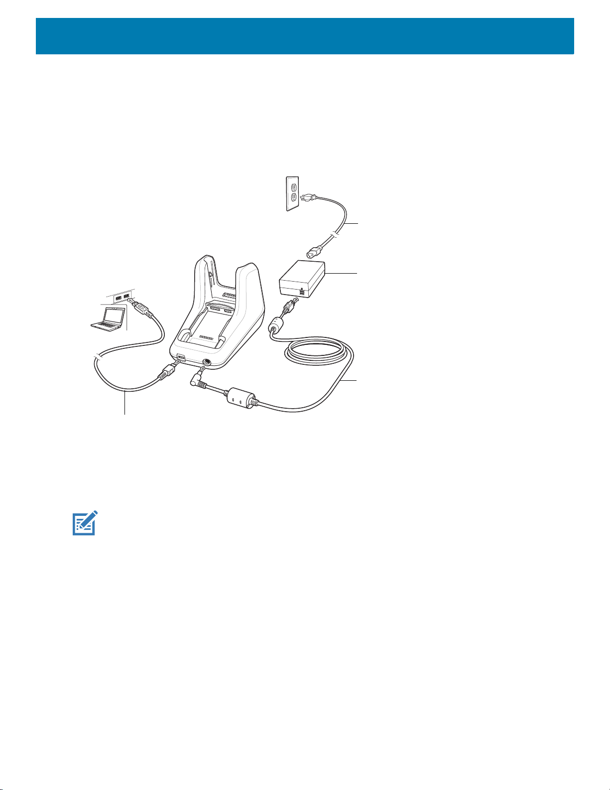
The 1-Slot USB Charge Cradle:
• Provides 9 VDC power for charging the mobile computer and charging the battery.
• Provides 4.2 VDC power to charge the spare battery.
• Provides a USB port for data communication between the mobile computer and a host computer or other
USB devices (e.g., a printer).
• Synchronizes information between the mobile computer and a host computer. With customized or third
party software, it can also synchronize the mobile computer with corporate databases.
32
Accessories
AC Line Cord
Power Supply
DC Line Cord
USB Cable
• Compatible with the following batteries:
• MC33XX 2740 mAh PowerPrecision+ standard battery.
• MC33XX 5200 mAh PowerPrecision+ extended battery.
• MC32N0 2740 mAh PowerPrecision standard battery.
• MC32N0 5200 mAh PowerPrecision extended battery.
Figure 13 1-Slot USB Charge Cradle Setup
Charging the MC33XX Battery
NOTE: To function properly, remove the entire rubber boot from the device before placing the device in a charging
cradle.
1. Ensure that the cradle is connected to power.
2. Slide the mobile computer into the slot in the cradle. The mobile computer Charge LED Indicator, indicates
the mobile computer battery charging status. For charging status, see Table 6 on page 35.
33

Figure 14 MC33XX Battery Charging
Accessories
3. Gently press down on the device to ensure proper contact.
4. When charging is complete, remove the mobile computer from the cradle slot.
Charging an MC33XX Spare Battery
1. Ensure that the cradle is connected to power.
2. Insert the spare battery into the cradle, bottom first, and pivot the top of the battery down onto the contact
pins.
34

Accessories
Figure 15 MC33XX Spare Battery Charging
3. Gently press down on the battery to ensure proper contact.
The Spare Battery Charging LED on the front of the cradle indicates the spare battery charging status.
4. When charging is complete, lift the battery out of the slot.
Battery Charging in 1- Slot USB Charge Cradle
The 1-Slot USB charge cradle charges the MC33XX’s main battery and a spare battery simultaneously.
The MC33XX’s Charge LED indicates the status of the battery charging in the MC33XX. See Table 6 on page
35 for charging status indications.
The spare battery charging LED on the cradle indicates the status of the spare battery charging in the cradle.
See below for charging status indications.
Table 6 Spare Battery LED Charging Indicators
Spare Battery LED (on cradle) Indication
Off • The battery is not charging.
• The battery is not inserted correctly in the cradle or
connected to a power source.
• Cradle is not powered.
Solid Amber • Battery is charging.
Solid Green • Battery charging is complete.
35

Accessories
Table 6 Spare Battery LED Charging Indicators (Continued)
Spare Battery LED (on cradle) Indication
Fast Blinking Red
2 blinks/second
Solid Red • Spare battery is charging and battery is at the end
The MC33XX 2740 mAh PowerPrecision+ standard battery charges from 0% to 90% in less than 2.2 hours at
room temperature.
The MC33XX 5200 mAh PowerPrecision+ extended battery charges from 0% to 90% in less than 3.8 hours at
room temperature.
The MC32N0 2740 mAh PowerPrecision standard battery charges from 0% to 90% in less than 3 hours at
room temperature.
The MC32N0 5200 mAh PowerPrecision extended battery charges from 0% to 90% in less than 5.5 hours at
room temperature.
Charging error, e.g.:
• Temperature is too low or too high.
• Charging has gone on too long without completion
(typically eight hours).
of useful life.
• Charging complete and battery is at the end of
useful life.
Charging Temperature
Charge batteries in temperatures from 0 °C to 40 °C (32 °F to 104 °F). Charging is intelligently controlled by the
MC33XX.
To accomplish this, for small periods of time, the MC33XX or cradle alternately enables and disables battery
charging to keep the battery at acceptable temperatures. The MC33XX or cradle indicates when charging is
disabled due to abnormal temperatures via its LED.
5-Slot Charge Only ShareCradle
CAUTION: Ensure that you follow the guidelines for battery safety described in Battery Safety Guidelines on page
200
.
The 5-Slot Charge Only ShareCradle:
• Provides 9 VDC power for operating the mobile computer and charging the battery.
• Simultaneously charges up to five mobile computers.
• Compatible with devices using the following batteries:
• MC33XX 2740 mAh PowerPrecision+ standard battery.
• MC33XX 5200 mAh PowerPrecision+ extended battery.
• MC32N0 2740 mAh PowerPrecision standard battery.
• MC32N0 5200 mAh PowerPrecision extended battery.
36

Accessories
AC Line Cord
DC Line Cord
Power Supply
Figure 16 5-Slot Charge Only ShareCradle Setup
Charging the MC33XX Battery
NOTE: To function properly, remove the entire rubber boot from the device before placing the device in a charging
cradle.
1. Ensure that the cradle is connected to power.
2. Slide the mobile computer into the slot in the cradle. The mobile computer Charge LED Indicator, indicates
the mobile computer battery charging status.
3. Gently press down on the device to ensure proper contact.
4. When charging is complete, remove the mobile computer from the cradle slot.
Battery Charging in the 5-Slot Charge Only ShareCradle
The MC33XX’s Charge LED indicates the status of the battery charging in the MC33XX. See Table 2 on page
23 for charging status indications.
The MC33XX 2740 mAh PowerPrecision+ standard battery charges from 0% to 90% in less than 2.2 hours at
room temperature.
The MC33XX 5200 mAh PowerPrecision+ extended battery charges from 0% to 90% in less than 3.8 hours at
room temperature.
The MC32N0 2740 mAh PowerPrecision standard battery charges from 0% to 90% in less than 3 hours at
room temperature.
37

The MC32N0 5200 mAh PowerPrecision extended battery charges from 0% to 90% in less than 5.5 hours at
AC Line Cord
DC Line Cord
Power Supply
Primary PortEthernet Cable
Router
room temperature.
Charging Temperature
Charge batteries in temperatures from 0 °C to 40 °C (32 °F to 104 °F). Charging is intelligently controlled by the
MC33XX.
To accomplish this, for small periods of time, the MC33XX or cradle alternately enables and disables battery
charging to keep the battery at acceptable temperatures. The MC33XX or cradle indicates when charging is
disabled due to abnormal temperatures via its LED.
5-Slot Ethernet ShareCradle
CAUTION: Ensure that you follow the guidelines for battery safety described in Battery Safety Guidelines on page
200
.
The 5-Slot Ethernet ShareCradle:
• Provides 9 VDC power for operating the mobile computer and charging the battery.
• Simultaneously charges up to five mobile computers.
• Compatible with devices using the following batteries:
• MC33XX 2740 mAh PowerPrecision+ standard battery.
• MC33XX 5200 mAh PowerPrecision+ extended battery.
• MC32N0 2740 mAh PowerPrecision standard battery.
• MC32N0 5200 mAh PowerPrecision extended battery.
Accessories
Figure 17 5-Slot Ethernet ShareCradle Setup
38

Accessories
Charging the MC33XX Battery
NOTE: To function properly, remove the entire rubber boot from the device before placing the device in a charging
cradle.
1. Ensure that the cradle is connected to power.
2. Slide the mobile computer into the slot in the cradle. The mobile computer amber Charge LED Indicator,
indicates the mobile computer battery charging status.
3. Gently press down on the device to ensure proper contact.
4. When charging is complete, remove the mobile computer from the cradle slot.
Battery Charging in the 5-Slot Ethernet ShareCradle
The MC33XX’s Charge LED indicates the status of the battery charging in the MC33XX. See Table 2 on page
23 for charging status indications.
The MC33XX 2740 mAh PowerPrecision+ standard battery charges from 0% to 90% in less than 2.2 hours at
room temperature.
The MC33XX 5200 mAh PowerPrecision+ extended battery charges from 0% to 90% in less than 3.8 hours at
room temperature.
The MC32N0 2740 mAh PowerPrecision standard battery charges from 0% to 90% in less than 3 hours at
room temperature.
The MC32N0 5200 mAh PowerPrecision extended battery charges from 0% to 90% in less than 5.5 hours at
room temperature.
Charging Temperature
Charge batteries in temperatures from 0 °C to 40 °C (32 °F to 104 °F). Charging is intelligently controlled by the
MC33XX.
To accomplish this, for small periods of time, the MC33XX or cradle alternately enables and disables battery
charging to keep the battery at acceptable temperatures. The MC33XX or cradle indicates when charging is
disabled due to abnormal temperatures via its LED.
Daisy-chaining Ethernet ShareCradles
Daisy-chain up to ten 5-Slot Ethernet ShareCradles to connect several cradles to an Ethernet network. Use
either a straight or crossover cable. Daisy-chaining should not be attempted when the main Ethernet
connection to the first cradle is 10 Mbps as throughput issues will almost certainly result.
To daisy-chain 5-Slot Ethernet ShareCradles:
1. Connect power to each 5-Slot Ethernet ShareCradle.
2. Connect an Ethernet cable to one of the ports on the switch and the other end to the Primary Port of the first
cradle.
3. Connect an Ethernet cable to the Secondary port of the first cradle.
39

Accessories
To Power Supply
To Next Cradle
To Power Supply
To Switch
Secondary Port
Primary Port
4. Connect the other end of the Ethernet cable to the Primary port of the next 5-Slot Ethernet ShareCradle.
Figure 18 Daisy-chaining 5-Slot Ethernet ShareCradles
5. Connect additional cradles as described in step 3 and 4.
Ethernet Settings
The following settings can be configured when using Ethernet communication:
• Proxy Settings
• Static IP.
Configuring Ethernet Proxy Settings
The MC33XX includes Ethernet cradle drivers. After inserting the MC33XX, configure the Ethernet connection:
1. Swipe down from the status bar to open the quick access panel and then touch .
2. Touch Ethernet.
3. Slide the switch to the ON position.
4. Place the MC33XX into the Ethernet cradle slot.
5. Touch and hold eth0 until the menu appears.
6. Touch Modify Proxy.
40

Accessories
7. Touch the Proxy drop-down list and select Manual.
Figure 19 Ethernet Proxy Settings
8. In the Proxy hostname field, enter the proxy server address.
9. In the Proxy port field, enter the proxy server port number.
NOTE: When entering proxy addresses in the Bypass proxy for field, do not use spaces or carriage returns be-
tween addresses.
10.In the Bypass proxy for text box, enter addresses for web sites that do not require to go through the proxy
server. Use the separator “|” between addresses.
11.Touch MODIFY.
12.Touch .
Configuring Ethernet Static IP Address
The MC33XX includes Ethernet cradle drivers. After inserting the MC33XX, configure the Ethernet connection:
1. Swipe down from the status bar to open the quick access panel and then touch .
2. Touch Ethernet.
3. Slide the switch to the ON position.
4. Place the MC33XX into the Ethernet cradle slot.
5. Touch eth0.
6. Touch Disconnect.
7. Touch eth0.
8. Touch the IP settings drop-down list and select Static.
41
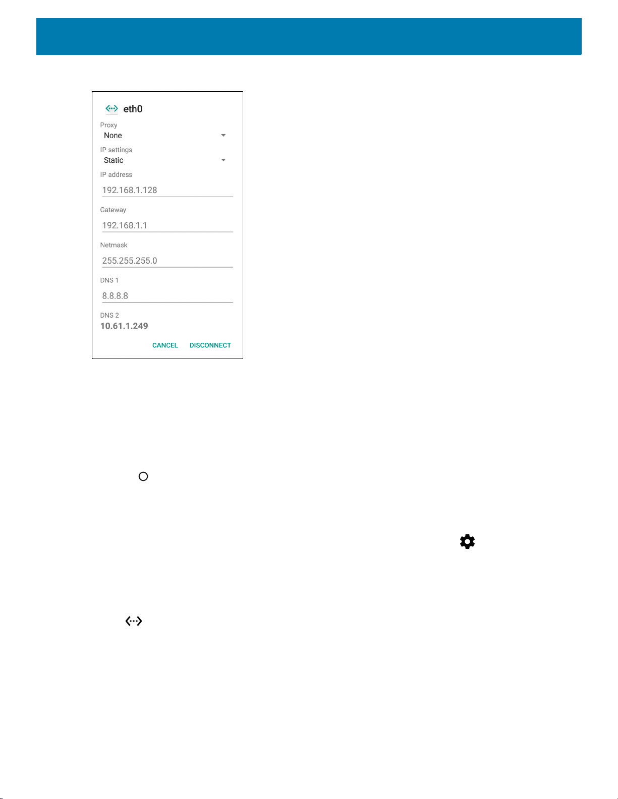
Figure 20 Static IP Settings
Accessories
9. In the IP address field, enter the proxy server address.
10.If required, in the Gateway field, enter a gateway address for the device.
11.If required, in the Netmask field, enter the network mask address
12.If required, in the DNS address fields, enter a Domain Name System (DNS) addresses.
13.Touch CONNECT.
14.Touch .
Establishing Ethernet Connection
1. Swipe down from the status bar to open the quick access panel and then touch .
2. Touch Ethernet.
3. Slide the Ethernet switch to the ON position.
4. Insert the device into a slot.
The icon appears in the Status bar.
5. Touch eth0 to view Ethernet connection details.
LED Indicators
There are two green LEDs on the side of the cradle. These green LEDs light and blink to indicate the data
transfer rate.
42

Accessories
AC Line Cord
DC Line Cord
Power Supply
Table 7 LED Data Rate Indicators
Data Rate 1000 LED 100/10 LED
1 Gbps On/Blink Off
100 Mbps Off On/Blink
10 Mbps Off On/Blink
5-Slot ShareCradle with 4-Slot Battery Charger
CAUTION: Ensure that you follow the guidelines for battery safety described in Battery Safety Guidelines on page
200
.
The 5-Slot ShareCradle with 4-Slot Battery Charger:
• Provides 9 VDC power for operating the mobile computer and charging the battery.
• Provides 4.2 VDC power for charging spare batteries.
• Simultaneously charges up to four mobile computers and four spare batteries.
• Compatible with the following batteries:
• MC33XX 2740 mAh PowerPrecision+ standard battery.
• MC33XX 5200 mAh PowerPrecision+ extended battery.
• MC32N0 2740 mAh PowerPrecision standard battery.
• MC32N0 5200 mAh PowerPrecision extended battery.
Figure 21 5-Slot ShareCradle with 4-Slot Battery Charger Setup
43

Charging the MC33XX Battery
NOTE: To function properly, remove the entire rubber boot from the device before placing the device in a charging
cradle.
1. Ensure that the cradle is connected to power.
2. Slide the mobile computer into the slot in the cradle. The mobile computer amber Charge LED Indicator,
indicates the mobile computer battery charging status.
3. Gently press down on the device to ensure proper contact.
4. When charging is complete, remove the mobile computer from the cradle slot.
Charging Spare Batteries
Insert the battery into the charger and gently press down on the battery to ensure proper contact.
Accessories
Battery Charging in the 5-Slot ShareCradle with 4-Slot Battery Charger
The MC33XX’s Charge LED or the spare battery LED indicates the status of the battery charging in the
MC33XX. See Table 2 on page 23 for charging status indications.
The MC33XX 2740 mAh PowerPrecision+ standard battery charges from 0% to 90% in less than 2.2 hours at
room temperature.
The MC33XX 5200 mAh PowerPrecision+ extended battery charges from 0% to 90% in less than 3.8 hours at
room temperature.
The MC32N0 2740 mAh PowerPrecision standard battery charges from 0% to 90% in less than 3 hours at
room temperature.
The MC32N0 5200 mAh PowerPrecision extended battery charges from 0% to 90% in less than 5.5 hours at
room temperature.
Charging Temperature
Charge batteries in temperatures from 0 °C to 40 °C (32 °F to 104 °F). Charging is intelligently controlled by the
MC33XX.
To accomplish this, for small periods of time, the MC33XX or cradle alternately enables and disables battery
charging to keep the battery at acceptable temperatures. The MC33XX or cradle indicates when charging is
disabled due to abnormal temperatures via its LED.
5-Slot Ethernet ShareCradle with 4-Slot Battery Charger
CAUTION: Ensure that you follow the guidelines for battery safety described in Battery Safety Guidelines on page
200
.
The 5-Slot Ethernet ShareCradle with 4-Slot Battery Charger:
44

Accessories
AC Line Cord
DC Line Cord
Power Supply
Primary Port
Ethernet Cable
Router
• Provides 9 VDC power for operating the mobile computer and charging the battery.
• Provides 4.2 VDC power for charging spare batteries.
• Simultaneously charges up to four mobile computers and four spare batteries.
• Compatible with the following batteries:
• MC33XX 2740 mAh PowerPrecision+ standard battery.
• MC33XX 5200 mAh PowerPrecision+ extended battery.
• MC32N0 2740 mAh PowerPrecision standard battery.
• MC32N0 5200 mAh PowerPrecision extended battery.
Figure 22 5-Slot Ethernet ShareCradle with 4-Slot Battery Charger Setup
Charging the MC33XX Battery
NOTE: To function properly, remove the entire rubber boot from the device before placing the device in a charging
cradle.
1. Ensure that the cradle is connected to power.
2. Slide the mobile computer into the slot in the cradle. The mobile computer amber Charge LED Indicator,
indicates the mobile computer battery charging status.
3. Gently press down on the device to ensure proper contact.
4. When charging is complete, remove the mobile computer from the cradle slot.
45

Accessories
Charging Spare Batteries
Insert the battery into the charger and gently press down on the battery to ensure proper contact.
Battery Charging in the 5-Slot Ethernet ShareCradle with 4-Slot Battery Charger
The MC33XX’s Charge LED or the spare battery LED indicates the status of the battery charging in the
MC33XX. See Table 2 on page 23 for charging status indications.
The MC33XX 2740 mAh PowerPrecision+ standard battery charges from 0% to 90% in less than 2.2 hours at
room temperature.
The MC33XX 5200 mAh PowerPrecision+ extended battery charges from 0% to 90% in less than 3.8 hours at
room temperature.
The MC32N0 2740 mAh PowerPrecision standard battery charges from 0% to 90% in less than 3 hours at
room temperature.
The MC32N0 5200 mAh PowerPrecision extended battery charges from 0% to 90% in less than 5.5 hours at
room temperature.
Charging Temperature
Charge batteries in temperatures from 0 °C to 40 °C (32 °F to 104 °F). Charging is intelligently controlled by the
MC33XX.
To accomplish this, for small periods of time, the MC33XX or cradle alternately enables and disables battery
charging to keep the battery at acceptable temperatures. The MC33XX or cradle indicates when charging is
disabled due to abnormal temperatures via its LED.
Daisy-chaining Ethernet Cradles
Daisy-chain up to ten 5-Slot Ethernet ShareCradle with 4-Slot Battery Chargers to connect several cradles to
an Ethernet network. Use either a straight or crossover cable. Daisy-chaining should not be attempted when
the main Ethernet connection to the first cradle is 10 Mbps as throughput issues will almost certainly result.
To daisy-chain 5-Slot Ethernet ShareCradle with 4-Slot Battery Chargers:
1. Connect power to each 5-Slot Ethernet ShareCradle with 4-Slot Battery Charger.
2. Connect an Ethernet cable to one of the ports on the switch and the other end to the Primary Port of the first
cradle.
3. Connect an Ethernet cable to the Secondary port of the first cradle.
4. Connect the other end of the Ethernet cable to the Primary port of the next 5-Slot Ethernet ShareCradle
with 4-Slot Battery Charger.
46
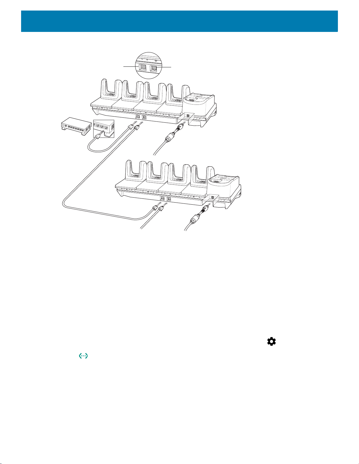
Accessories
To Power Supply
To Next Cradle
To Power Supply
To Switch
Secondary Port
Primary Port
Figure 23 Daisy-chaining 5-Slot Ethernet ShareCradle with 4-Slot Battery Chargers
5. Connect additional cradles as described in step 3 and 4.
Ethernet Settings
The following settings can be configured when using Ethernet communication:
• Proxy Settings
• Static IP.
Configuring Ethernet Proxy Settings
The MC33XX includes Ethernet cradle drivers. After inserting the MC33XX, configure the Ethernet connection:
1. Swipe down from the status bar to open the quick access panel and then touch .
2. Touch Ethernet.
3. Slide the switch to the ON position.
4. Place the MC33XX into the Ethernet cradle slot.
5. Touch and hold eth0 until the menu appears.
6. Touch Modify Proxy.
7. Touch the Proxy drop-down list and select Manual.
47

Accessories
Figure 24 Ethernet Proxy Settings
8. In the Proxy hostname field, enter the proxy server address.
9. In the Proxy port field, enter the proxy server port number.
NOTE: When entering proxy addresses in the Bypass proxy for field, do not use spaces or carriage returns be-
tween addresses.
10.In the Bypass proxy for text box, enter addresses for web sites that do not require to go through the proxy
server. Use the separator “|” between addresses.
11.Touch MODIFY.
12.Touch .
Configuring Ethernet Static IP Address
The MC33XX includes Ethernet cradle drivers. After inserting the MC33XX, configure the Ethernet connection:
1. Swipe down from the status bar to open the quick access panel and then touch .
2. Touch Ethernet.
3. Slide the switch to the ON position.
4. Place the MC33XX into the Ethernet cradle slot.
5. Touch eth0.
6. Touch Disconnect.
7. Touch eth0.
8. Touch the IP settings drop-down list and select Static.
48

Figure 25 Static IP Settings
Accessories
9. In the IP address field, enter the proxy server address.
10.If required, in the Gateway field, enter a gateway address for the device.
11.If required, in the Netmask field, enter the network mask address
12.If required, in the DNS address fields, enter a Domain Name System (DNS) addresses.
13.Touch CONNECT.
14.Touch .
Establishing Ethernet Connection
1. Swipe down from the status bar to open the quick access panel and then touch .
2. Touch Ethernet.
3. Slide the Ethernet switch to the ON position.
4. Insert the device into a slot.
The icon appears in the Status bar.
5. Touch eth0 to view Ethernet connection details.
LED Indicators
There are two green LEDs on the side of the cradle. These green LEDs light and blink to indicate the data
transfer rate.
49

Accessories
Table 8 LED Data Rate Indicators
Data Rate 1000 LED 100/10 LED
1 Gbps On/Blink Off
100 Mbps Off On/Blink
10 Mbps Off On/Blink
4-Slot Spare Battery Charger
CAUTION: Ensure that you follow the guidelines for battery safety described in Battery Safety Guidelines on page
200
.
The 4-Slot Battery Charger:
• Charges up to four MC33XX spare batteries.
• Provides 4.2 VDC power to charge the spare battery.
• Compatible with the following batteries:
• MC33XX 2740 mAh PowerPrecision+ standard battery.
• MC33XX 5200 mAh PowerPrecision+ extended battery.
• MC32N0 2740 mAh PowerPrecision standard battery.
• MC32N0 5200 mAh PowerPrecision extended battery.
Charging Spare Batteries
1. Connect the charger to a power source.
2. Insert the battery into the charger and gently press down on the battery to ensure proper contact.
50

Figure 26 4-Slot Battery Charger Setup
AC Line Cord
DC Line Cord
Power Supply
Accessories
Battery Charging
Spare Battery Charging
Each Battery Charging LED indicates the status of the battery charging in each slot. The table below describes
the Battery Charging LED status.
Table 9 Battery LED Charging Indicators
LED Indication
Off • The battery is not charging.
• The battery is not inserted correctly in the cradle or
connected to a power source.
• Cradle is not powered.
Solid Amber • Battery is charging.
Solid Green • Battery charging is complete.
Fast Blinking Red
2 blinks/second
Charging error, e.g.:
• Temperature is too low or too high.
• Charging has gone on too long without completion
(typically eight hours).
Solid Red • Spare battery is charging and battery is at the end
of useful life.
• Charging complete and battery is at the end of
useful life.
51

Accessories
The MC33XX 2740 mAh PowerPrecision+ standard battery charges from 0% to 90% in less than 2.2 hours at
room temperature.
The MC33XX 5200 mAh PowerPrecision+ extended battery charges from 0% to 90% in less than 3.8 hours at
room temperature.
The MC32N0 2740 mAh PowerPrecision standard battery charges from 0% to 90% in less than 3 hours at
room temperature.
The MC32N0 5200 mAh PowerPrecision extended battery charges from 0% to 90% in less than 5.5 hours at
room temperature.
Charging Temperature
Charge batteries in temperatures from 0 °C to 40 °C (32 °F to 104 °F). Charging is intelligently controlled by the
MC33XX.
To accomplish this, for small periods of time, the changer alternately enables and disables battery charging to
keep the battery at acceptable temperatures. The charger indicates when charging is disabled due to abnormal
temperatures via its LED.
20-Slot Spare Battery Charger
CAUTION: Ensure that you follow the guidelines for battery safety described in Battery Safety Guidelines on page
200
.
The 20-Slot Battery Charger:
• Charges up to twenty MC33XX spare batteries.
• Provides 4.2 VDC power to charge the spare battery.
• Compatible with the following batteries:
• MC33XX 2740 mAh PowerPrecision+ standard battery.
• MC33XX 5200 mAh PowerPrecision+ extended battery.
• MC32N0 2740 mAh PowerPrecision standard battery.
• MC32N0 5200 mAh PowerPrecision extended battery.
Charging Spare Batteries
1. Connect the charger to a power source.
2. Insert the battery into the charger and gently press down on the battery to ensure proper contact.
52

Figure 27 20-Slot Battery Charger Setup
AC Line Cord
DC Line Cord
Power Supply
Accessories
Battery Charging
Spare Battery Charging
Each Battery Charging LED indicates the status of the battery charging in each slot. The table below describes
the Battery Charging LED status.
Table 10 Battery LED Charging Indicators
LED Indication
Off • The battery is not charging.
• The battery is not inserted correctly in the cradle or
connected to a power source.
• Cradle is not powered.
Solid Amber • Battery is charging.
Solid Green • Battery charging is complete.
Fast Blinking Red
2 blinks/second
Charging error, e.g.:
• Temperature is too low or too high.
• Charging has gone on too long without completion
(typically eight hours).
Solid Red • Spare battery is charging and battery is at the end
of useful life.
• Charging complete and battery is at the end of
useful life.
53
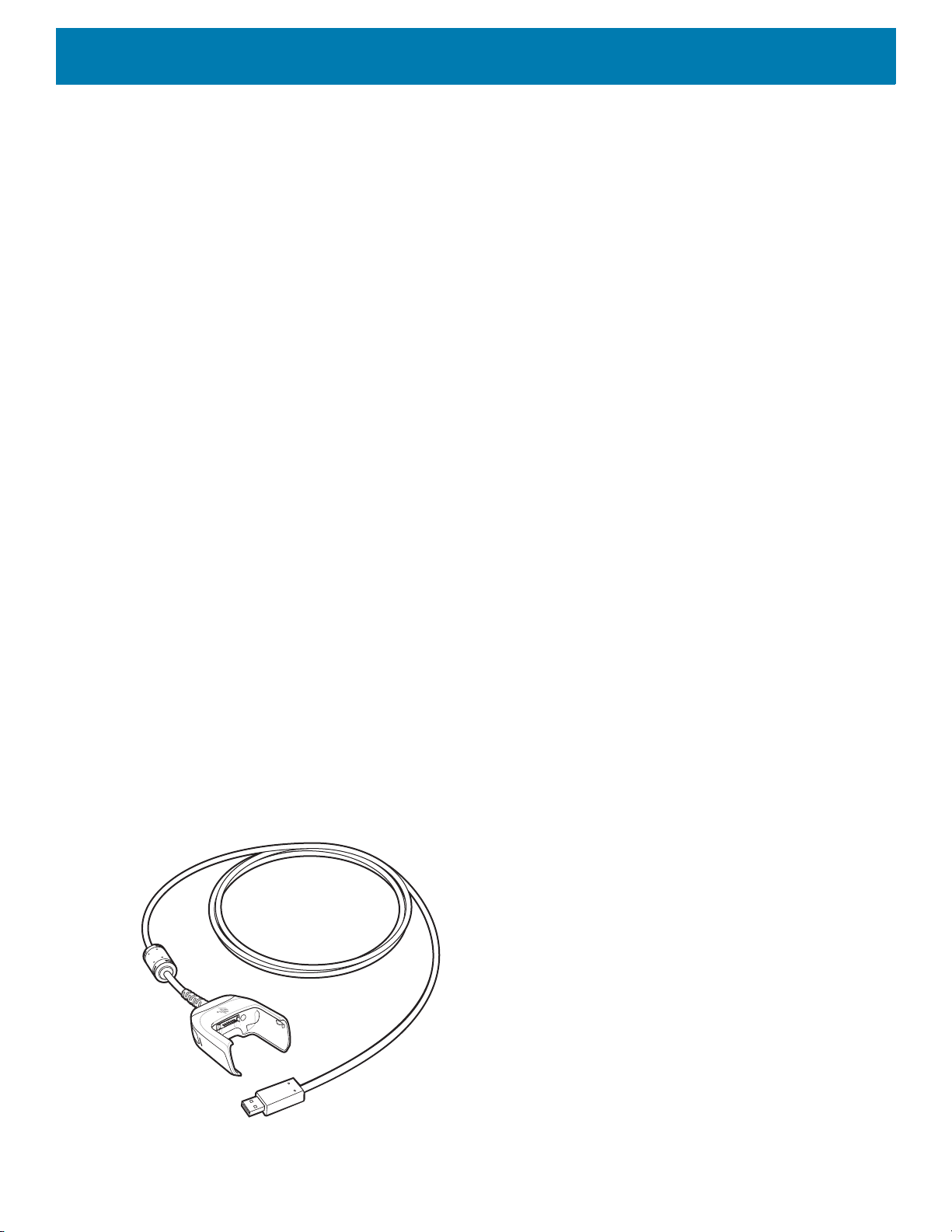
Accessories
The MC33XX 2740 mAh PowerPrecision+ standard battery charges from 0% to 90% in less than 3 hours at
room temperature.
The MC33XX 5200 mAh PowerPrecision+ extended battery charges from 0% to 90% in less than 5.5 hours at
room temperature.
The MC32N0 2740 mAh PowerPrecision standard battery charges from 0% to 90% in less than 3 hours at
room temperature.
The MC32N0 5200 mAh PowerPrecision extended battery charges from 0% to 90% in less than 5.5 hours at
room temperature.
Charging Temperature
Charge batteries in temperatures from 0 °C to 40 °C (32 °F to 104 °F). Charging is intelligently controlled by the
MC33XX.
To accomplish this, for small periods of time, the changer alternately enables and disables battery charging to
keep the battery at acceptable temperatures. The charger indicates when charging is disabled due to abnormal
temperatures via its LED.
USB Charge Cable
The USB Charge Cable:
• Provides 5 VDC power to charge the battery.
• Provides power and/or communication with the host computer over USB to the device.
• Compatible with devices using the following batteries:
• MC33XX 2740 mAh PowerPrecision+ standard battery.
• MC33XX 5200 mAh PowerPrecision+ extended battery.
• MC32N0 2740 mAh PowerPrecision standard battery.
• MC32N0 5200 mAh PowerPrecision extended battery.
The USB Charge Cable snaps onto the bottom of the MC33XX and removes easily when not in use. When
attached to the MC33XX allows charging only.
Figure 28 USB Charge Cable
54

Accessories
Connecting the USB Charge Cable to Device
NOTE: To function properly, remove the entire rubber boot from the device before placing the device in a charging
cradle.
To connect the USB Charge Cable to the device, insert the USB Charge Cable straight onto the device until
the device touches the bottom of the cable cup.
Figure 29 Connecting the USB Charge Cable
Connecting the USB Charge Cable to Host Computer
To connect the USB Charge Cable to a host computer:
1. Connect the USB Charge Cable to the MC33XX.
2. Connect the USB connector of the cable to a host computer.
55

Accessories
Figure 30 Connecting USB Charge Cable to Host Computer
Main Battery Charging
The device’s Charging/Notification LED indicates the status of the battery charging in the device.
NOTE: Charging using a host computer USB port could take longer.
To achieve the best charging results use only Zebra charging accessories and batteries. Charge batteries at
room temperature with the MC33XX in sleep mode.
Charging the Device
To charge the device using the USB Charge Cable:
1. Connect the USB Charge Cable to the MC33XX.
2. Connect the USB connector of the power supply.
3. Plug the power supply into a power outlet.
56

Figure 31 Charging the Device
Accessories
Main Battery Charging
The device’s Charging/Notification LED indicates the status of the battery charging in the device.
NOTE: In many cases the 90% charge provides plenty of charge for daily use.
To achieve the best charging results use only Zebra charging accessories and batteries. Charge batteries at
room temperature with the MC33XX in sleep mode.
The MC33XX 2740 mAh PowerPrecision+ standard battery charges from 0% to 90% in less than 2.2 hours at
room temperature.
The MC33XX 5200 mAh PowerPrecision+ extended battery charges from 0% to 90% in less than 6 hours at
room temperature.
The MC32N0 2740 mAh PowerPrecision standard battery charges from 0% to 90% in less than 3 hours at
room temperature.
The MC32N0 5200 mAh PowerPrecision extended battery charges from 0% to 90% in less than 6 hours at
room temperature.
Disconnecting the USB Charge Cable
To disconnect the USB Charge Cable from the MC33XX:
1. Grasp the cable cup in one hand (by pinching the front and back) and the device in the other hand.
2. Remove the device by pulling straight up.
57

Accessories
Figure 32 Disconnecting the USB Charge Cable
MC33XX Charge Only Adapter
Use the MC33XX Charge Only Adapter for backwards compatibility with the MC32N0 cradles and the MC33XX
mobile computer.
• MC33XX Charge Only Adapter supports the MC32N0 1-Slot USB Cradle, MC32N0 4-Slot Charge Only
Cradle, and MC32N0 4-Slot Ethernet Cradle.
• MC33XX Charge Only Adapter provides charge only; no communication when used with the MC32N0
cradles.
• MC32N0 1-Slot USB Cradle provides 5.4V DC to charge the device.
• MC32N0 1-Slot USB Cradle (with the MC33XX Charge Only Adapter) is compatible with an MC33XX
mobile computer charging either MC33XX PowerPrecision+ batteries or MC32N0 PowerPrecision
batteries, but the MC32N0 1-Slot USB Cradle spare battery slot is only compatible with MC32N0
PowerPrecision batteries.
Adapter Installation
To install the MC33XX Charge Only Adapter into the MC32N0 Cradle:
1. Clean the MC32N0 cradle and contacts with an alcohol wipe, using a back and forth motion with your
finger. For more information about cleaning, see Maintenance and Troubleshooting.
58

Accessories
Figure 33 Clean MC32N0 Cradle
2. Peel and remove the adhesive from the back of the adapter.
Figure 34 Peel and Remove Adhesive
3. Insert the adapter into the MC32N0 cradle and adhere to the bottom of the cradle.
Figure 35 Insert Adapter into Cradle and Adhere
4. Insert the MC33XX device into the MC32N0 cradle.
59
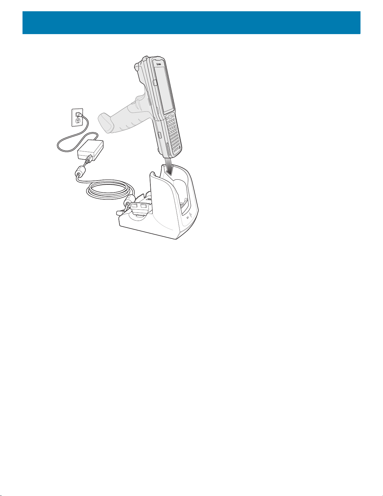
Accessories
Figure 36 Insert MC33XX device into MC32N0 Cradle
The MC33XX 2740 mAh PowerPrecision+ standard battery charges from 0% to 90% in less than 3 hours at
room temperature.
The MC33XX 5200 mAh PowerPrecision+ extended battery charges from 0% to 90% in less than 5.5 hours at
room temperature.
The MC32N0 2740 mAh PowerPrecision standard battery charges from 0% to 90% in less than 3 hours at
room temperature.
The MC32N0 5200 mAh PowerPrecision extended battery charges from 0% to 90% in less than 5.5 hours at
room temperature.
Charging Temperature
Charge batteries in temperatures from 0 °C to 40 °C (32 °F to 104 °F). Charging is intelligently controlled by the
MC33XX.
To accomplish this, for small periods of time, the MC33XX or cradle alternately enables and disables battery
charging to keep the battery at acceptable temperatures. The MC33XX or cradle indicates when charging is
disabled due to abnormal temperatures via its LED.
MC33XX-G Rubber Boot
The rubber boot provides additional protection to the MC33XX-G.
To attach the rubber boot:
1. Slide the top of the MC33XX-G into the top of the rubber boot.
60

Accessories
Figure 37 Attach Top of Rubber Boot
2. Grasp the bottom of the rubber boot and place over the bottom of the MC33XX-G.
Figure 38 Attach Bottom of Rubber Boot
NOTE: To function properly, remove the entire rubber boot from the device before placing the device in a charging
cradle or rigid holster.
MC33XX-R Rubber Boot
The rubber boot provides additional protection to the MC33XX-R. The rubber boot is comprised of two pieces;
one for the mobile computer and one for the turret cup.
To attach the rubber boot:
1. Insert the rubber boot for the turret cup into the rubber boot for the mobile computer, to form a single piece,
if it is not already attached.
61

Accessories
Figure 39 Two Piece Rubber Boot
2. Slide the top of the MC33XX-R into the top of the rubber boot.
Figure 40 Attach Top of Rubber Boot
3. Grasp the bottom of the rubber boot and place over the bottom of the MC33XX-R.
Figure 41 Attach Bottom of Rubber Boot
NOTE: To function properly, remove the entire rubber boot from the device before placing the device in a charging
cradle or rigid holster.
62
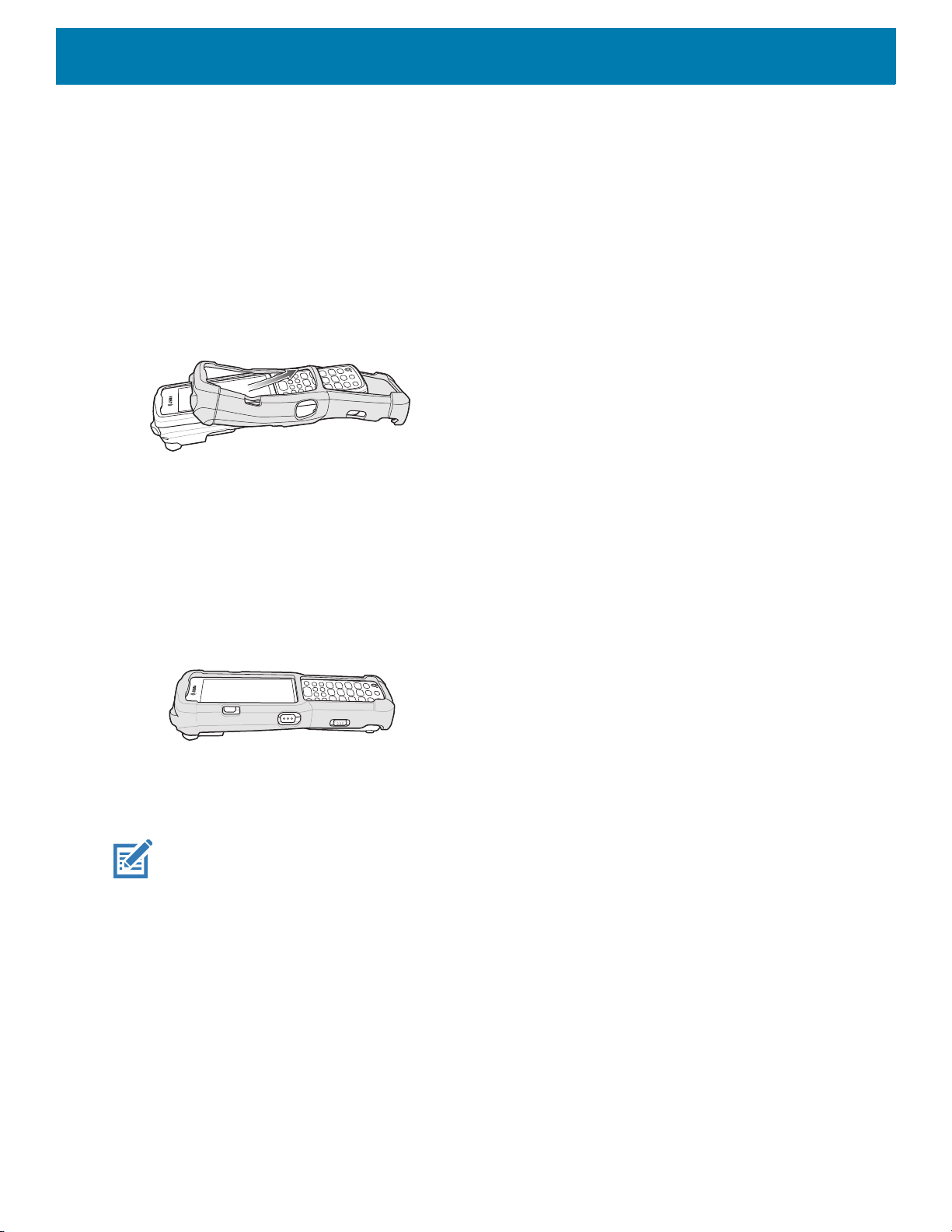
MC33XX-S Rubber Boot
The rubber boot provides additional protection to the MC33XX-S.
To attach the rubber boot:
1. Slide the bottom of the MC33XX-S into the bottom of the rubber boot.
Figure 42 Attach Bottom of Rubber Boot
Accessories
2. Grasp the top of the rubber boot and place over the top of the MC33XX-S.
Figure 43 Attach Top of Rubber Boot
NOTE: To function properly, remove the entire rubber boot from the device before placing the device in a charging
cradle or rigid holster.
Rigid Holster
The Rigid Holster provides a holder for the MC33XX-R/S. It consists of a mobile computer holder and a
detachable belt clip. Press the release button to remove the detachable belt clip.
63

Figure 44 Plastic Holster
Detachable Belt Clip
Release Button
Mobile Computer Holder
Mobile Computer Holder
Clip Release
Figure 45 Attaching the Rigid Holster
Accessories
The Rigid Holster holds the mobile computer on a belt or waist band.
To insert the mobile computer, slide the mobile computer into the Rigid Holster with the screen facing the user.
To remove the mobile computer, press and lift to remove the mobile computer.
64

Accessories
Figure 46 Insert and Remove the Mobile Computer
NOTE: To function properly, remove the entire rubber boot from the device before placing the device in a rigid
holster.
MC33XX-G Fabric Holster
The fabric holster provides a soft holder for the mobile computer. It consists of a fabric mobile computer holder,
a detachable shoulder strap and a belt strap. See figures below to attach the fabric holster to a belt and
shoulder strap.
Belt Strap
Attach the fabric holster to a belt or waist band.
65

Accessories
Figure 47 Attach the Fabric Holster to a Belt
Shoulder Strap
Attach the fabric holster to a shoulder strap.
Figure 48 Attach the Fabric Holster to a Shoulder Strap
66
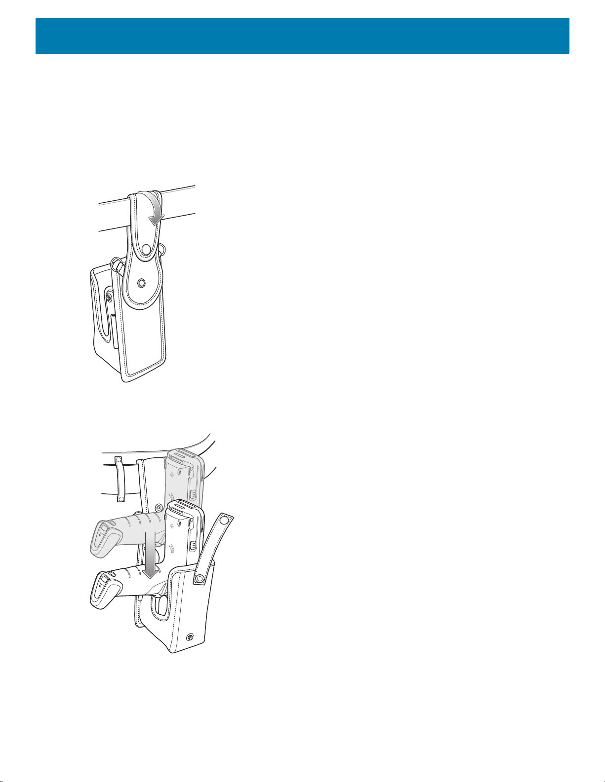
Using the Belt Strap
The fabric holster holds the MC33XX-G on a belt or waist band.
1. Secure the belt strap over the belt or waistband and snap into place.
Figure 49 Secure Belt Strap On Belt
Accessories
2. To insert the MC33XX-G, slide the mobile computer into the fabric holster with the screen facing the user.
Figure 50 Insert MC33XX-G
3. Secure the MC33XX-G with the restraining strap and place over the MC33XX-G to secure in place.
67

Figure 51 Secure with Strap
Accessories
4. To remove the MC33XX-G, unsnap the restraining strap to release. Lift the MC33XX-G out of the fabric
holster.
Using the Shoulder Strap
1. Connect the clips on the shoulder strap to the rings on the fabric holster.
2. Place the shoulder strap over your head and rest on your shoulder.
68

Figure 52 Shoulder Strap
Accessories
3. Lift the strap and insert the MC33XX-G into the holster.
4. Secure the strap to hold the MC33XX-G in place.
MC33XX-R/S Fabric Holster
The fabric holster provides a soft holder for the mobile computer. It consists of a fabric mobile computer holder,
a detachable shoulder strap and a belt clip. See figures below to attach the fabric holster to a belt and shoulder
strap.
Belt Clip
Attach the fabric holster to a belt or waist band.
69
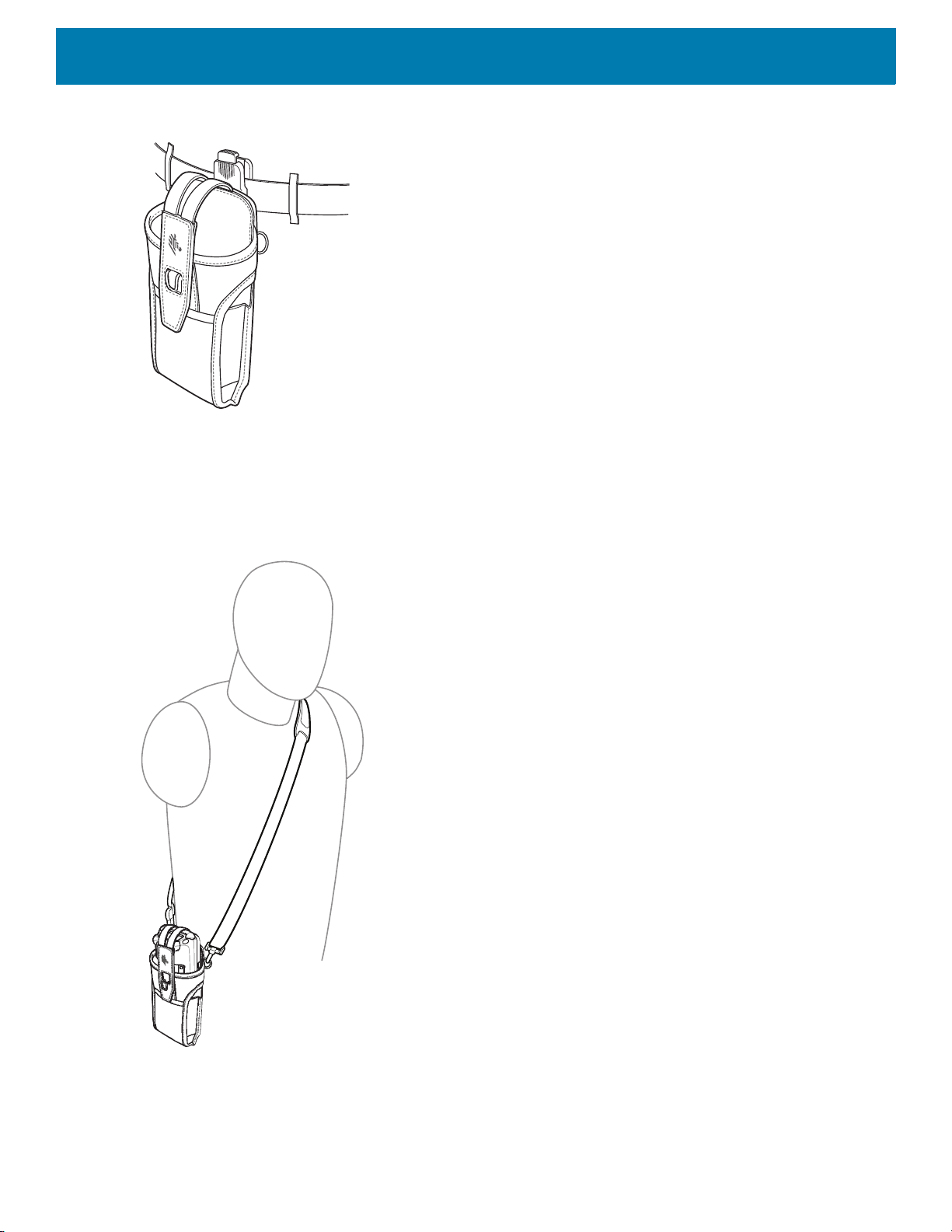
Figure 53 Attach the Fabric Holster to a Belt
Shoulder Strap
Attach the fabric holster to a shoulder strap.
Accessories
Figure 54 Attach the Fabric Holster to a Shoulder Strap
Using the Belt Clip
The fabric holster holds the MC33XX-R/S on a belt or waist band.
70

Accessories
1. Secure the belt clip on the fabric holster, if it is not already attached.
Figure 55 Secure Belt Clip On Fabric Holster
2. Secure the belt clip on the belt or waistband.
Figure 56 Secure Belt Clip On Belt
3. To insert the MC33XX-R/S, slide the mobile computer into the fabric holster with the screen facing the user.
Figure 57 Insert MC33XX-R/S
4. Secure the MC33XX-R/S with the restraining strap and place over the MC33XX-R/S to secure in place.
71

Accessories
Figure 58 Secure with Strap
5. To remove the MC33XX-R/S, lift the restraining strap to release. Lift the MC33XX-R/S out of the fabric
holster.
Using the Shoulder Strap
1. Connect the clips on the shoulder strap to the rings on the fabric holster.
2. Place the shoulder strap over your head and rest on your shoulder.
72

Figure 59 Shoulder Strap
Accessories
3. Lift the strap and insert the MC33XX-R/S into the holster.
4. Secure the strap to hold the MC33XX-R/S in place.
Un-powered Forklift Mount
The Un-powered Forklift Mount allows the user to place the MC33XX in a holder while installed on a forklift.
However, it does not provide charging or communication to the terminal. The Forklift Mount can be installed on
a square surface or roll bar of a forklift and supports portrait (vertical) orientation.
73

Figure 60 Forklift Mount
Installation
Accessories
To assemble the Forklift Mount:
1. Secure the RAM Clamp Base to the Forklift Mounting Surface.
2. Attach the RAM Socket Arm to the RAM Clamp Base and Forklift Mount Holder.
3. Turn the Socket Arm hand-screw clockwise until tight.
4. Insert the device in the Forklift Mount Holder.
5. Secure the device with the rubber strap and snap into place.
74

Figure 61 Forklift Mount Assembly
4
Accessories
5
2
3
2
RAM Clamp Base Forklift Mounting SurfaceRAM Socket ArmForklift Mount Holder
1
Replacement Hand Strap for MC33XX-G
To install the hand strap:
1. Thread the lanyard loop through the opening near the base of the trigger handle.
Figure 62 Insert Loop Through Handle Slot
2. Insert the top end of the hand strap through the loop.
75
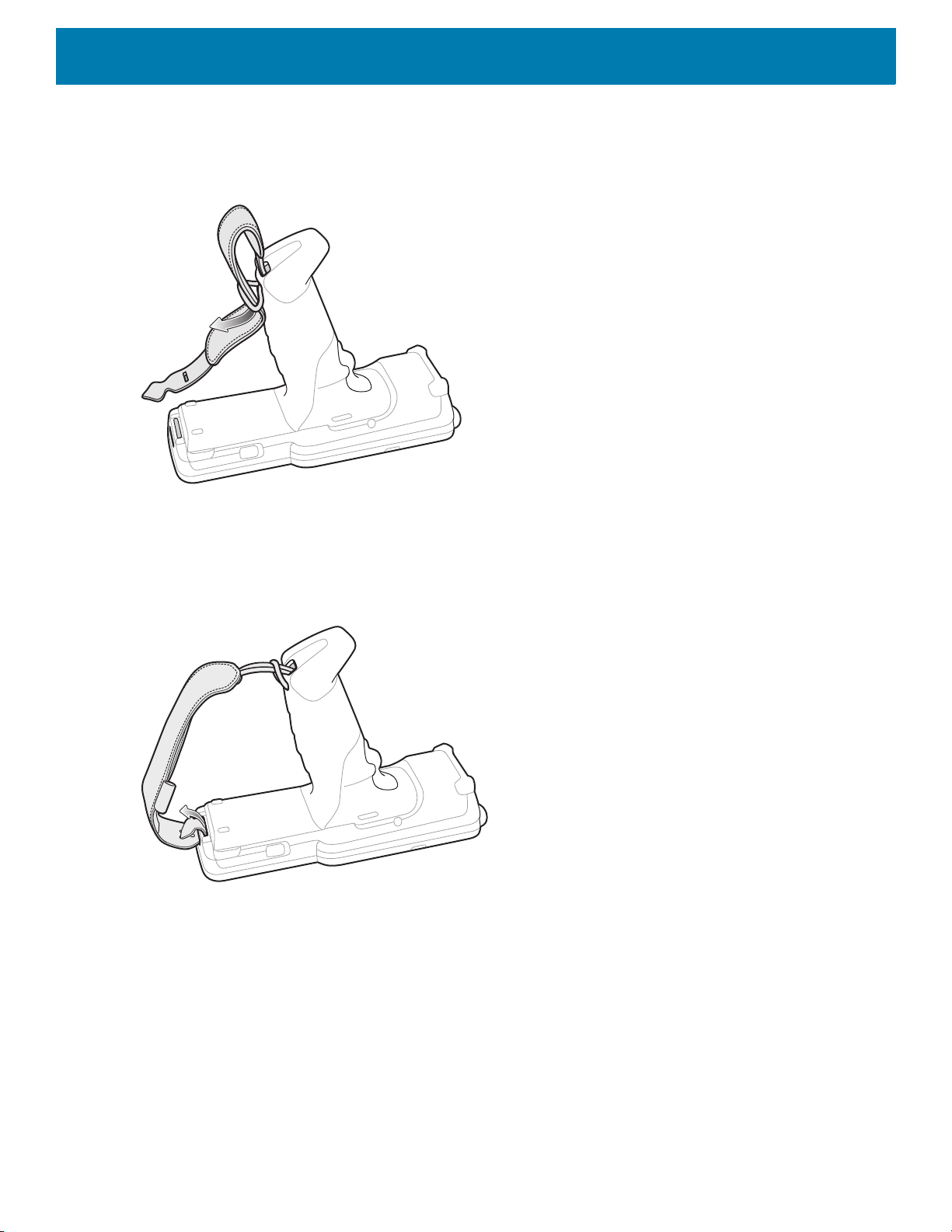
Accessories
Figure 63 Thread Hand Strap Through Loop
3. Thread the hand strap through the lanyard.
4. Pull the hand strap through the loop.
5. Thread the end of the hand strap with the tab through the slot on the bottom of the MC33XX-G.
Figure 64 Thread Tab Through Slot
6. Slide the tab through the slit in the hand strap so that the tip of the tab is facing away from the MC33XX-G.
Replacement Hand Strap for MC33XX-R/S
To install the hand strap:
1. Thread the end of the hand strap with the tab through the slot toward the top of the MC33XX-R/S.
76

Accessories
Figure 65 Thread Tab Through Top Slot
2. Slide the tab through the slit in the hand strap so that the tip of the tab is facing away from the
MC33XX-R/S.
Figure 66 Slide Tab Through Slit
3. Thread the end of the hand strap with the velcro through the slot at the bottom of the MC33XX-R/S.
77
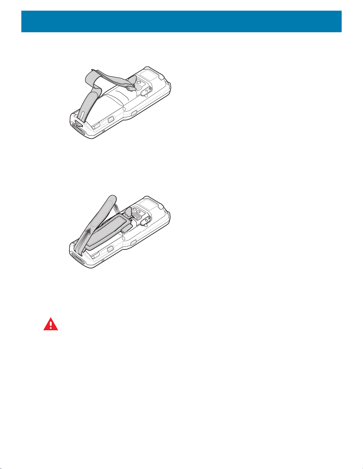
Accessories
Figure 67 Thread Velcro Through Bottom Slot
4. Pull the strap to the desired length and secure using the velcro.
Figure 68 Pull Strap and Secure Velcro
Lanyard
The lanyard is an optional accessory for securing the MC33XX-R or MC33XX-S device to the user, which is
comprised of multiple pieces. The lanyard can be worn using the cross-body strap, or it can be worn on the
belt, after removing the cross-body strap.
WARNING: This accessory is not intended to be used with the MC33XX-G device.
78
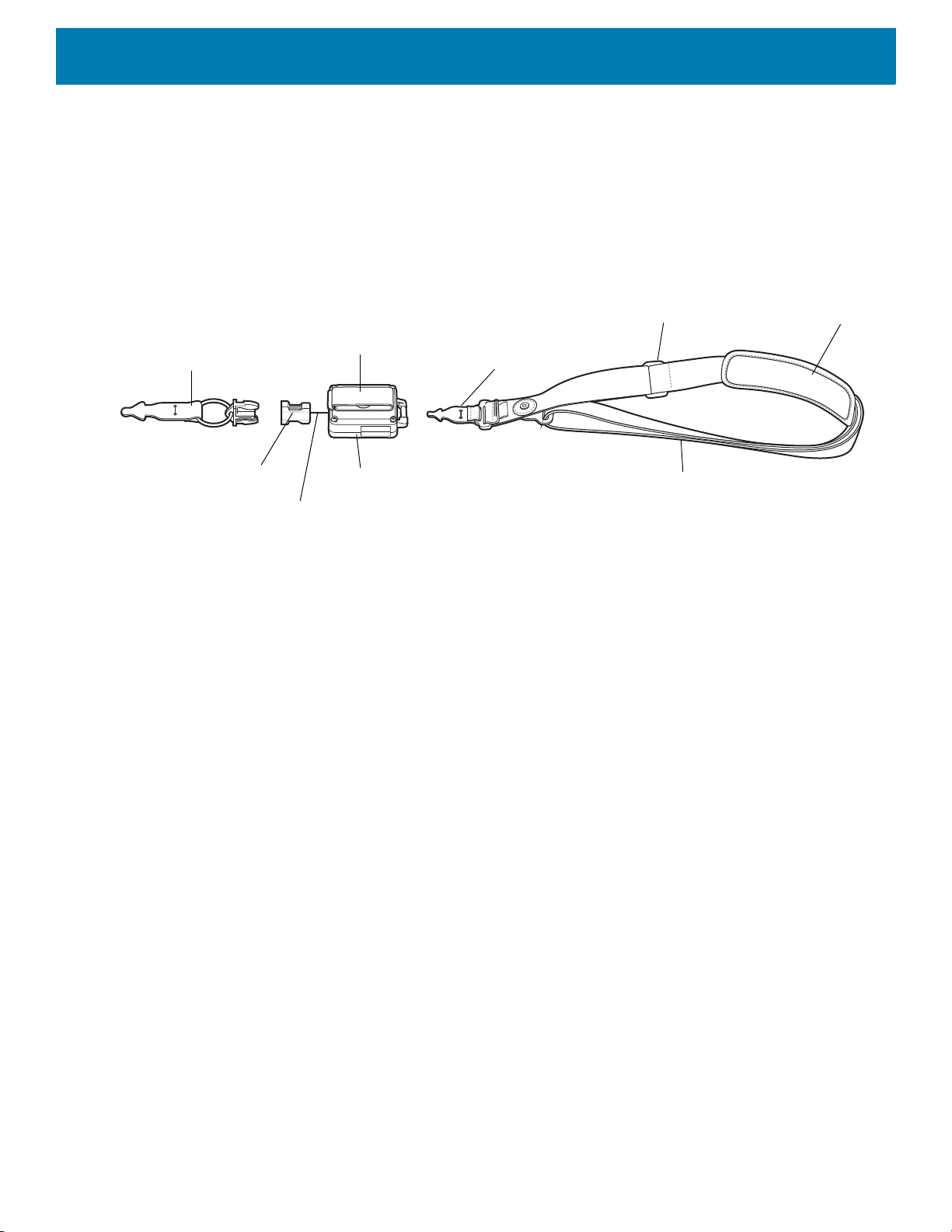
Figure 69 Lanyard
Cross-body Strap
Strap Extender
Shoulder Pad
Retractor
Device to Retractor
Interface
Quick Release Button
Retractor to Strap
Interface
Belt Clip
Lanyard Cord
Accessories
Install Lanyard on MC33XX
To install the lanyard on the MC33XX:
1. Thread the tab of the Device to Retractor Interface through the slot at the bottom of the MC33XX.
79

Accessories
Figure 70 Thread Tab Through Slot
2. Slide the tab through the slit in the Device to Retractor Interface.
Figure 71 Slide Tab Through Slit
Using the Cross-body Strap
1. Place arm through strap and over the head to wear cross-body.
80

Figure 72 Cross-body Lanyard
Accessories
2. If needed, slide the Strap Extender to adjust the length of the Cross-body Strap to the desired length.
3. If needed, slide the Shoulder Pad along the Cross-body Strap to adjust the position of the Shoulder Pad for
comfort.
Using the Belt Clip
To use the lanyard on a belt:
1. Detach the Cross-body Strap from the Retractor. To do this, unthread the tab of the Retractor to Strap
Interface from the slot in the Retractor.
81

Accessories
Figure 73 Remove Cross-body Strap
2. Place the Belt Clip on a belt or waistband.
Figure 74 Belt Clip Lanyard
Charging the MC33XX with the Lanyard
To charge the MC33XX when using the lanyard:
1. Press the Quick Release Button on the Retractor.
2. Place the MC33XX in the charging cradle.
The Device to Retractor Interface remains attached to the MC33XX, while charging.
82

USB Communication
Introduction
This chapter provides information for transferring files between the device and a host computer.
Transferring Files with a Host Computer via USB
Connect the device to a host computer using a USB cable or a USB cradle to transfer files between the
device and the host computer.
When connecting the device to a host computer, follow the host computer’s instructions for connecting
and disconnecting USB devices, to avoid damaging or corrupting files.
Transferring Files
NOTE: Use Transfer files to copy files between the device (internal memory or microSD card) and the host com-
puter.
1. Connect a USB cable to the device or place the device into a USB cradle.
2. Pull down the Notification panel and touch USB charging this device.
By default, Charge this device is selected.
Figure 75 Use USB to Dialog Box
3. Touch Transfer files.
4. On the host computer, open a file explorer application.
5. Locate the device as a portable device.
83

6. Open the SD card or the Internal storage folder.
7. Copy files to and from the device or delete files as required.
Transferring Photos
To transfer photos using Photo Transfer Protocol:
NOTE: Use Photo Transfer Protocol (PTP) to copy photos from either the microSD card or internal memory to the host com-
puter.
1. Connect USB cable to the device or place the device into a USB cradle. See Accessories for setup
information.
2. Pull down the Notification panel and touch USB charging this device.
3. Touch Transfer photos (PTP).
4. On the host computer, open a file explorer application.
5. Open the SD card or the Internal storage folder.
USB Communication
6. Copy or delete photos as required.
Disconnect from the Host Computer
To disconnect the device from the host computer:
CAUTION: Carefully follow the host computer’s instructions to unmount the microSD card and disconnect USB devices cor-
rectly to avoid losing information.
1. On the host computer, unmount the device.
2. Remove the USB from the device or remove the device from the cradle.
84

DataWedge
Introduction
This chapter applies to DataWedge on Android devices. DataWedge is an application that reads data,
processes the data and sends the data to an application.
Accessing DataWedge
To access DataWedge:
1. Swipe up from the bottom of the Home screen and touch .
Basic Scanning
Scanning can be performed using the following:
•Imager
• Laser scanner
Barcode Capture with Imager
To capture barcode data:
1. Ensure that an application is open on the device and a text field is in focus (text cursor in text field).
2. Point the top of the device at a barcode.
3. Press and hold the Scan button or Trigger.
The red laser aiming pattern turns on to assist in aiming.
4. Ensure the barcode is within the area formed by the cross-hairs in the aiming pattern. The aiming
dot is used for increased visibility in bright lighting conditions.
The Scan LEDs light green and a beep sounds, by default, to indicate the barcode was decoded
successfully. Note that when the device is in Pick List Mode, the device does not decode the barcode
until the center of the crosshair touches the barcode.
5. Release the scan button or Trigger.
6. The barcode content data appears in the text field.
85

DataWedge
Barcode Capture with Laser Scanner
To capture barcode data:
1. Ensure that an application is open on the device and a text field is in focus (text cursor in text field).
2. Point the top of the device at a barcode.
3. Point the scan exit window at a bar code.
4. Press and hold the Scan button.
The red scan line turns on to assist in aiming. Ensure that the scan line crosses every bar and space of the
barcode.
The Scan LEDs light green and a beep sounds, by default, to indicate the barcode was decoded
successfully.
Figure 76 Data Capture
Profiles
5. Release the scan button.
6. The captured data appears in the text field.
DataWedge is based on profiles and plug-ins. A profile contains information on how DataWedge should
behave with different applications.
Profile information consists of:
• Associated application
• Input plug-in configurations
• Output plug-in configurations
• Process plug-in configurations.
Using profiles, each application can have a specific DataWedge configuration. For example, each user
application can have a profile which outputs scanned data in the required format when that application comes
to the foreground. DataWedge can be configured to process the same set of captured data differently based on
the requirements of each application.
86

Profile0
DataWedge
DataWedge includes the following pre-configured profiles which support specific built-in applications:
• Visible profiles:
• Profile0 - created automatically the first time DataWedge runs. Generic profile used when there are no
user created profiles associated with an application.
• Launcher - enables scanning when the Launcher is in foreground.
• DWDemo - provides support for the DWDemo application.
Some Zebra applications are capable of capturing data by scanning. DataWedge is pre-loaded with private
and hidden profiles for this purpose. There is no option to modify the private profiles.
Profile0 can be edited but cannot be associated with an application. That is, DataWedge allows manipulation
of plug-in settings for Profile0 but it does not allow assignment of a foreground application. This configuration
allows DataWedge to send output data to any foreground application other than applications associated with
user-defined profiles when Profile0 is enabled.
Profile0 can be disabled to allow DataWedge to only send output data to those applications which are
associated in user-defined profiles. For example, create a profile associating a specific application, disable
Profile0 and then scan. DataWedge only sends data to the application specified in the user-created profile.
This adds additional security to DataWedge enabling the sending of data only to specified applications.
Plug-ins
A plug-in is a software module utilized in DataWedge to extend its functionality to encompass technologies
such as barcode scanning. The plug-ins can be categorized into three types based on their operations:
• Input Plug-ins
• Output Plug-ins
• Process Plug-ins.
Input Plug-ins
An Input Plug-in supports an input device, such as a barcode scanner contained in, or attached to the device.
DataWedge contains base plug-ins for these input devices.
Barcode Scanner Input Plug-in – The Barcode Scanner Input Plug-in is responsible for reading data from the
integrated barcode scanner and supports different types of barcode readers including laser, imager and
internal camera. Raw data read from the barcode scanner can be processed or formatted using Process
Plug-ins as required. DataWedge has built-in feedback functionality for the barcode scanner to issue user
alerts. The feedback settings can be configured according to user requirement.
Process Plug-ins
Process Plug-ins are used in DataWedge to manipulate the received data according to the requirement,
before sending to the foreground application via the Output Plug-in.
• Basic Data Formatting Process Plug-in – The Basic Data Formatting Plug-in allows DataWedge to add a
prefix and/or a suffix to the captured data before passing it to an Output Plug-in.
87

• Advanced Data Formatting Process Plug-in – The Advanced Data Formatting Plug-in allows
DataWedge to apply rules (actions to be performed based on defined criteria) to the data received via an
input plug-in before passing it to an Output Plug-in.
Output Plug-ins
Output Plug-ins are responsible for sending the data from Input Plug-ins to a foreground application on the
device.
• Keystroke Output Plug-in – The Keystroke Output Plug-in collects and sends data received from the Input
Plug-in to the foreground applications by emulating keystrokes.
• Intent Output Plug-in – The Intent Output Plug-in collects and sends data received from the Input Plug-ins
to foreground applications using the Android Intent mechanism.
• IP Output Plug-in – The IP Output Plug-in collects and sends data received from the Input Plug-ins to a
host computer via a network connection. Captured data can be sent over an IP network to a specified IP
address and port using either TCP or UDP transport protocols.
Profiles Screen
DataWedge
To launch DataWedge, swipe up from the bottom of the screen and touch . By default, three profiles appear:
•Profile0
• Launcher
•DWDemo
Profile0 is the default profile and is used when no other profile can be applied.
Figure 77 DataWedge Profiles Screen
Profile names are color coded. Enabled profiles are white and disabled profiles are gray.
To configure a profile touch the profile name.
88
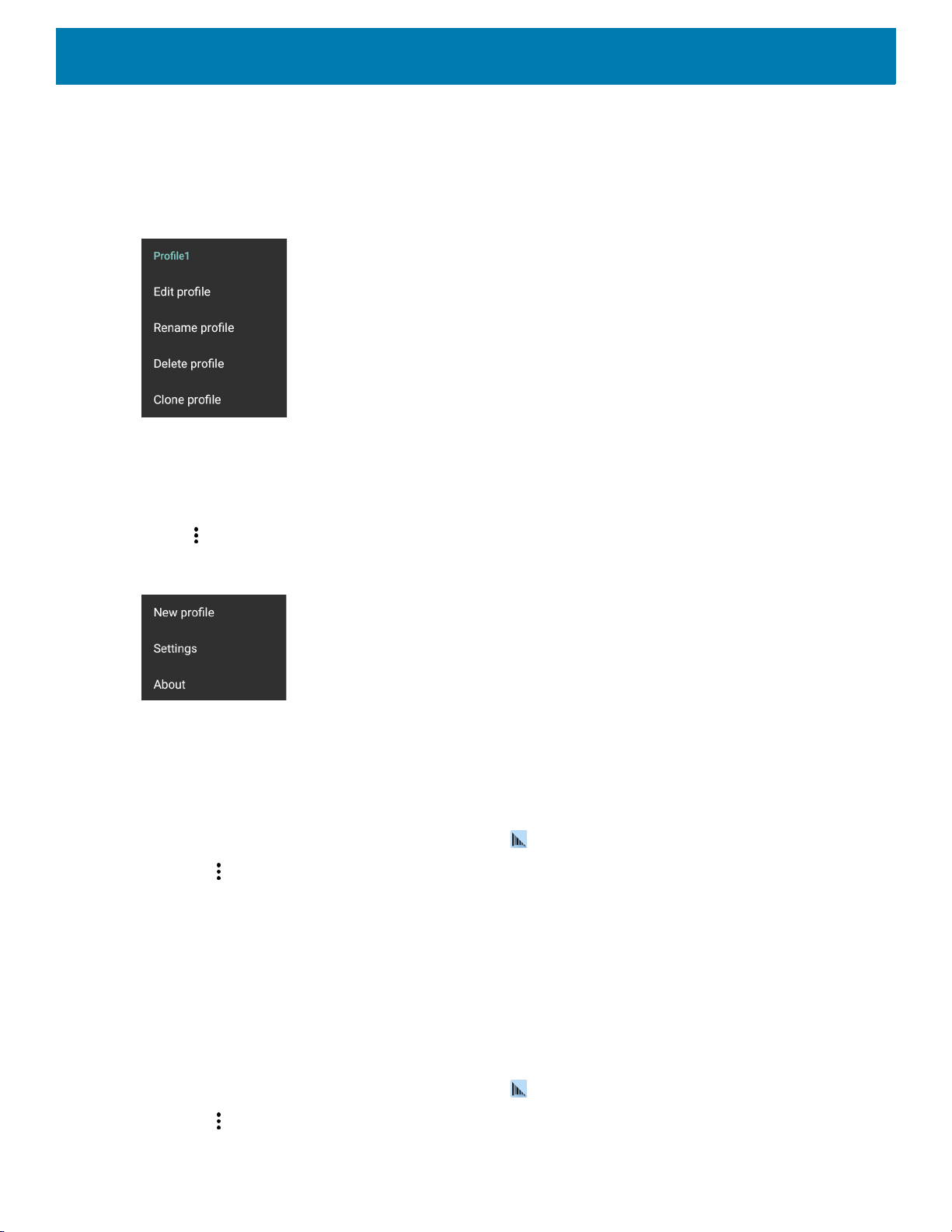
Profile Context Menu
Touch and hold a profile to open a context menu that allows additional actions to be performed on the selected
profile.
Figure 78 Profile Context Menu
The profile context menu allows the profile to be edited (same as just tapping on a profile), renamed or deleted.
Options Menu
DataWedge
Touch to open the options menu.
Figure 79 DataWedge Options Menu
The menu provides options to create a new profile, access to general DataWedge settings and DataWedge
version information.
Disabling DataWedge
1. Swipe up from the bottom of the screen and touch .
2. Touch .
3. Touch Settings.
4. Touch DataWedge enabled.
The blue check disappears from the checkbox indicating that DataWedge is disabled.
Creating a New Profile
To create a new profile:
1. Swipe up from the bottom of the screen and touch .
2. Touch .
89

3. Touch New profile.
4. In the New profile dialog box, enter a name for the new profile. It is recommended that profile names be
unique and made up of only alpha-numeric characters (A-Z, a-z, 0-9).
Figure 80 New Profile Name Dialog Box
5. Touch OK.
The new profile name appears in the DataWedge profile screen.
Profile Configuration
DataWedge
To configure the Profile0 or a user-created profile, touch the profile name.
Figure 81 Profile Configuration Screen
The configuration screen lists the following sections:
• Profile enabled
• Applications
• Data Capture Plus (DCP)
• Barcode Input
• SimulScan Input
• Keystroke output
• Intent Output
90

• IP Output.
Associating Applications
Use Applications option to associate applications with this profile. User created profiles should be associated
with one or more applications and its activities.
1. Touch Associated apps. A list of applications/activities associated with the profile displays. Initially the list
does not contain any applications/activities.
Figure 82 Associated Apps Screen
DataWedge
2. Touch .
3. Touch New app/activity.
91
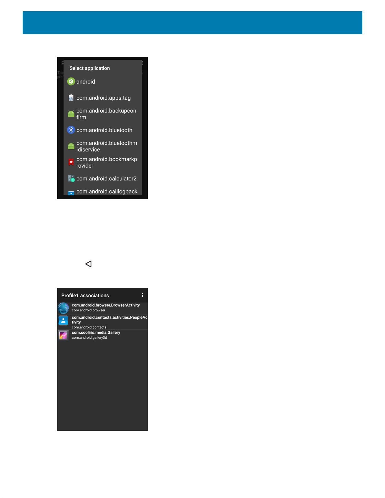
Figure 83 Select Application Menu
DataWedge
4. In the Select application screen, select the desired application from the list.
5. In the Select activity menu, selecting the activity adds that application/activity combination to the
associated application list for that profile. Selecting * as the activity results in all activities within that
application being associated to the profile. During operation, DataWedge tries to match the specific
application/activity combinations with the foreground application/activity before trying to match the general
application/* combinations.
6. Touch .
Figure 84 Selected Application/Activity
92

Data Capture Plus
DCP Button
Data Capture Plus (DCP) is a DataWedge feature that enables the user to initiate data capture by touching a
designated part of the screen. A variable screen overlay acts like a scan button.
Figure 85 Minimized Data Capture Panel
DataWedge
The DataWedge profile configuration screen allows the user to configure how the DCP appears on the screen
once the particular profile is enabled. The DCP is hidden by default. Enabling DCP option displays seven
additional configuration parameters.
Figure 86 Data Capture Panel Settings
• Enable - Select to enable Data Capture Plus (default - disabled).
93

DataWedge
• Dock button on - Select position of the button.
• Left or right - Allows user to place the button on either the right or left edge of the screen.
• Left only - Places the button on left edge of the screen.
• Right only - Places the button on the right edge of the screen.
• Start in - Select the initial DCP state.
• Fullscreen mode - DCP covers the whole screen.
• Button mode - DCP displays as a circular button on the screen and can be switched to fullscreen mode.
• Button only mode - DCP displays as a circular button on the screen and cannot be switched to
fullscreen mode.
• Button highest position - Select the top of the range the user is allowed to move the DCP, given as a
percent of the screen height (default - 0).
• Button lowest position - Select the bottom of the range the user is allowed to move the DCP, given as a
percent of the screen height (default - 100).
• Drag detect time - Select the time in milliseconds that the scanner waits before activating scanner. This
allows the user to drag the button without initiating scanner (default - 100 ms, maximum 1000 ms).
NOTE: The DCP does not appear if the scanner is disabled in the profile even though the Enabled option is set.
In Button mode, the user can place DCP in full screen mode by dragging the button over Fullscreen mode.
The overlay covers the screen.
Figure 87 Maximized DCP
Swipe down to return to button mode.
Barcode Input
Use the Barcode Input options to configure the Barcode Scanner Input Plug-in for the profile.
94

DataWedge
Enabled
Enables or disables this plug-in. A check in the checkbox indicates that the plug-in is enabled.
Scanner Selection
Configures which scanning device to use for barcode data capture when the profile is active.
• Auto - The software automatically determines the best scanning device.
• Serial SSI Scanner - Scanning is performed using the 1D imager.
• 2D Barcode Imager - Scanning is performed using the 2D Imager.
• Bluetooth Scanner - Scanning is performed using the optional Bluetooth scanner.
• RS6000 Bluetooth Scanner - Scanning is performed using the RS6000 Bluetooth scanner.
• DS3678 Bluetooth Scanner - Scanning is performed using the DS3678 Bluetooth scanner.
Auto Switch to Default on Event
This feature configures DataWedge to select an external scanner as the default scanning device immediately
upon connection and revert to a built-in scanner when the external scanner is disconnected. External scanners
include those connecting by Bluetooth, serial cable or snap-on module. Disabled by default. This is only
available when Scanner Selection is set to Auto.
This helps reduce scanning workflow interruptions when a Bluetooth scanner is introduced and/or it becomes
disconnected due to losing power or moving out of range.
For Bluetooth scanners, if the device was not previously paired, a pairing barcode displays prior to automatic
connection.
• Disabled - No scanner switching occurs when an external scanner is connected or disconnected (default).
• On connect - Selects the external scanner as the default scanning device immediately upon connection.
• On disconnect - Reverts to a built-in scanner based on its position in an internally managed scanner list
(which varies by host device). This is usually the scanner most recently used prior to the external
connection (see notes below).
• On connect/disconnect - Selects an external scanner as the default scanning device immediately upon
connection. Upon disconnection, reverts to the scanner set as the default prior to the external connection.
NOTE: The system selects the default scanner based on the connection state and the scanner's position in an internally
managed scanner list. If the newly connected scanner is lower in the scanner list than the one currently selected as the default scanner, the newly connected scanner becomes the default scanner.
On devices with only one built-in scanner or imager, On disconnect reverts to that built-in scanner or imager.
Configure Scanner Settings
Select Configure Scanner Settings to set the following:
• Select scanner to set parameters
• Decoders
• Decoder params
• UPC/EAN params
• Reader params
• Scan params
• UDI params
95

DataWedge
• Multibarcode params
• Keep enabled on suspend
Select Scanner to Set Parameters
Select a scanner from the available options to set the parameters for or select All Scanners.
Decoders
Configures which barcode decoders are enabled or disabled. For best performance disable all unnecessary
decoders.
Touch Decoders. The Barcode input screen appears. A check in the checkbox indicates that the decoder is
enabled. By default the most commonly used decoders are enabled (shown below with an asterisk). The
supported decoders are:
NOTE: DataWedge supports the decoders listed below but not all are validated on this device.
Table 11 Supported Decoders
Decoders
SE965
Internal 1D Laser
Australian
Postal
Aztec --XXXXX--
Canadian
Postal
Chinese 2 of 5OOOOOOO
Codabar XXXXXXX
Code 11 OOOOOOO
Code 128 XXXXXXX
Code 39 XXXXXXX
Code 93 OOOOOOO
Composite AB--OOOOO--
Composite C--OOOOO--
Discrete 2 of 5OOOOOOO
Datamatrix --XXXXX--
--OOOOO--
-- O -- O -- -- --
Internal Imager
SE4750-SR, SE4770 & SE4850-ER
RS507/RS507X
RS6000
DS2278
DS3678
LI3678
96

DataWedge
Table 11 Supported Decoders (Continued)
Decoders
SE965
RS6000
DS2278
DS3678
LI3678
Internal 1D Laser
Dutch Postal --OOOOO--
DotCode OXOOOOO
EAN13 XXXXXXX
EAN8 XXXXXXX
GS1 DataBarXXXXXXX
GS1 DataBar
Expanded
GS1 DataBar
Limited
GS1
Datamatrix
GS1 QRCode -- O -- O O O --
HAN XIN -- O -- O O O --
Interleaved 2
of 5
XXXXXXX
OOOOOOO
-- O -- O O O --
OOOOOOO
Internal Imager
SE4750-SR, SE4770 & SE4850-ER
RS507/RS507X
Japanese
Postal
Korean 3 of 5OOOOOOO
MAIL MARK --X--XXX--
Matrix 2 of 5 OOOOOOO
Maxicode --XXXXX--
MicroPDF --OOOOO--
MicroQR --OOOOO--
MSI OOOOOOO
PDF417 --XXXXX--
QR Code --XXXXX--
Decoder
Signature
TLC 39 OOOOOOO
--OOOOO--
-- O O O O -- --
97
DataWedge
Table 11 Supported Decoders (Continued)
Decoders
SE965
RS6000
DS2278
DS3678
LI3678
Internal 1D Laser
Trioptic 39 OOOOOOO
UK Postal --OOOOO--
UPCA XXXXXXX
UPCE0 XXXXXXX
UPCE1 DOOOOOO
US4state --OOOOO--
US4state FICS--OOOOO--
US Planet --OOOOO--
US Postnet --OOOOO--
Touch to return to the previous screen.
Internal Imager
SE4750-SR, SE4770 & SE4850-ER
RS507/RS507X
Decoder Params
Use Decode Params to configure individual decoder parameters.
NOTE: Not all parameter options are available with all scanners. See the DataWedge app on each device for the available
scanners and parameter options.
Codabar
• CLSI Editing - Enable this parameter to strip the start and stop characters and insert a space after the first,
fifth, and tenth characters of a 14-character Codabar symbol. Enable this feature if the host system requires
this data format (default - disabled).
• Length1 - Use to set decode lengths (default - 6). See Decode Lengths for more information.
• Length2 - Use to set decode lengths (default - 55). See Decode Lengths for more information.
• NOTIS Editing - Enable this parameter to strip the start and stop characters from a decoded Codabar
symbol. Enable this feature if the host system requires this data format (default - disabled).
• Redundancy - Sets the reader to read the barcode twice before accepting data. A check in the checkbox
indicates that redundancy is enabled (default - enabled).
Code 11
• Length1 - Use to set decode lengths (default - 4). See Decode Lengths for more information.
• Length2 - Use to set decode lengths (default - 55). See Decode Lengths for more information.
98

DataWedge
• Redundancy - Sets the reader to read the barcode twice before accepting data. A check in the checkbox
indicates that redundancy is enabled (default - enabled).
• Report Check Digit - Transmit Code 11 data with or without the check digit. A check in the checkbox
indicates to send Code 11 data with check digit (default - disabled).
• Verify Check Digit - Check the integrity of all Code 11 symbols to verify that the data complies with the
specified check digit algorithm. This selects the check digit mechanism for the decoded Code 11 barcode.
• No Check Digit - Do not verify check digit.
• 1 Check Digit - Barcode contains one check digit (default).
• 2 Check Digits - Barcode contains two check digits.
Code128
• Code128 Reduced Quiet Zone - Enables decoding of margin-less Code 128 barcodes (default - disabled).
• Ignore Code128 FCN4 - When enabled, and a Code 128 barcode has an embedded FNC4 character, it will
be removed from the data and the following characters will not be changed. When the feature is disabled,
the FNC4 character will not be transmitted but the following character will have 128 added to it (default disabled).
• Check ISBT Table - The ISBT specification includes a table that lists several types of ISBT barcodes that
are commonly used in pairs. If ISBT128 Concat Mode is set, enable Check ISBT Table to concatenate only
those pairs found in this table. Other types of ISBT codes are not concatenated. A check in the checkbox
indicates that redundancy is enabled (default - disabled).
• Enable GS1-128 - Set the GS1 128 subtype. A check in the checkbox indicates that the option is enabled
(default - enabled).
• Enable ISBT128 - Set the ISBT128 subtype. A check in the checkbox indicates that the option is enabled
(default - enabled).
• Enable Plain Code128 - Set the Plain Code128 subtype. Enables other (non-EAN or ISBT) Code 128
subtypes. A check in the checkbox indicates that the option is enabled (default - enabled).
• ISBT128 Concatenation Mode - Select an option for concatenating pairs of ISBT code types:
• Concat Mode Never - Do not concatenate pairs of ISBT codes encountered (default).
• Concat Mode Always - There must be two ISBT codes in order to decode and perform concatenation.
Does not decode single ISBT symbols.
• Concat Mode Auto - Decodes and concatenates pairs of ISBT codes immediately. If only a single ISBT
symbol is present, the device must decode the symbol the number of times set via DataWedge
Configuration 4 - 11 Redundancy - Code128 before transmitting its data to confirm that there is no
additional ISBT symbol.
• Length1 - Use to set decode lengths (default - 0). See Decode Lengths for more information.
• Length2 - Use to set decode lengths (default - 55). See Decode Lengths for more information.
• Redundancy - Sets the reader to read the barcode twice before accepting data. A check in the checkbox
indicates that redundancy is enabled (default - disabled).
• Security Level - The scanner offers four levels of decode security for Code 128 barcodes. Select
increasing levels of security for decreasing levels of barcode quality. There is an inverse relationship
99

DataWedge
between security and scanner aggressiveness, so choose only that level of security necessary for any
given application.
• Security Level 0 - This setting allows the scanner to operate in its most aggressive state, while
providing sufficient security in decoding most “in-spec” barcodes.
• Security Level 1 - This setting eliminates most misdecodes (default).
• Security Level 2 - Select this option if Security level 1 fails to eliminate misdecodes.
• Security Level 3 - If Security Level 2 is selected and misdecodes still occur, select this security level.
Be advised, selecting this option is an extreme measure against mis-decoding severely out of spec
barcodes. Selecting this level of security significantly impairs the decoding ability of the scanner. If this
level of security is needed, try to improve the quality of the barcodes.
Code39
• Code39 Reduced Quiet Zone - Enables decoding of margin-less Code 39 barcodes (default - disabled).
• Convert Code39 To Code32 - Code 32 is a variant of Code 39 used by the Italian pharmaceutical industry.
Scan the appropriate barcode below to enable or disable converting Code 39 to Code 32 (default disabled).
• Full ASCII- Code 39 Full ASCII is a variant of Code 39 that pairs characters to encode the full ASCII
character set. To enable or disable Code 39 Full ASCII (default - disabled),
• Length1 - Use to set decode lengths (default - 0). See Decode Lengths for more information.
• Length2 - Use to set decode lengths 4 (default - 55). See Decode Lengths for more information.
• Redundancy - Sets the reader to read the barcode twice before accepting data. A check in the checkbox
indicates that redundancy is enabled (default - disabled).
• Report Check Digit - Transmit Code 39 data with or without the check digit. A check in the checkbox
indicates to send Code 39 data with check digit (default - disabled).
• Report Code32 Prefix - Scan the appropriate barcode to enable or disable adding the prefix character “A”
to all Code 32 barcodes (default - disabled).
• Security Level - Options: Security level 0, Security Level 1, Security Level 2
(default - Security level 1).
• Security Level 0 - This setting allows the scanner to operate in its most aggressive state, while
providing sufficient security in decoding most “in-spec” barcodes.
• Security Level 1 - This setting eliminates most misdecodes (default).
• Security Level 2 - Select this option if Security level 1 fails to eliminate misdecodes.
• Security Level 3 - If Security Level 2 is selected and misdecodes still occur, select this security level.
Be advised, selecting this option is an extreme measure against mis-decoding severely out of spec
barcodes. Selecting this level of security significantly impairs the decoding ability of the scanner. If this
level of security is needed, try to improve the quality of the barcodes.
• Verify Check Digit - Enable this feature to check the integrity of all Code 39 symbols to verify that the data
complies with a specified check digit algorithm. The digital scanner decodes only those Code 39 symbols
that include a modulo 43 check digit. Enable this feature only if the Code 39 symbols contain a modulo 43
check digit (default - disabled).
and Security Level 3
Code93
• Length1 - Use to set decode lengths (default - 0). See Decode Lengths for more information.
• Length2 - Use to set decode lengths (default - 55). See Decode Lengths for more information.
• Redundancy - Sets the reader to read the barcode twice before accepting data. A check in the checkbox
indicates that redundancy is enabled (default - disabled).
100
 Loading...