

Page 1
Ht-146
H Series
Thermal Printer
User’s Manual
User’s Manual No. 980342-001 Rev. A
©2001 Zebra Technologies Corporation
Page 2
COPYRIGHT NOTICE
This document contains information proprietary to Zebra Technologies Corporation. This docu
ment and the information contained within is copyrighted by Zebra Technologies Corporation and
may not be duplicated in full or in part by any person without written approvalfromZebraTechnol
ogies Corporation. While every effort has been made to keep the information contained within cur
rent and accurate as of the date of publication, no guarantee is given or implied that the document
is error-free or that it is accurate with regard to any specification. Zebra Technologies Corporation
reserves the right to make changes, for the purpose of product improvement, at any time.
TRADEMARKS
Ht-146 is a service mark and Zebra is a trademark of Zebra Technologies Corporation. Windows
and MS-DOS are registered trademarks of Microsoft Corp. All other marks are trademarks or regis
tered trademarks of their respective holders.
Ht-146 Thermal Printer
European Council
Directive
89/336/EEC EMC Directive EN55022-B, 1998 RF Emissions control
92/31/EE EMC Directive EN55024, 1998
Compliance to Standards
Immunity to Electromag-
netic Disturbances
-
-
-
-
73/23/EEC
Low Voltage
Directive
EMC Directive EN61000-3-2 Harmonic Emissions
EMC Directive EN61000-3-3 Voltage Variation
EN60950 IEC950 Product Safety
FCC - Declaration Of Conformity:
Model: Ht-146 conforms to the following specification:
FCC Part 15, Subpart B, Section 15.107(a) and Section
15.109(a) Class B digital device
Supplemental Information:
This device complies with Part 15 of the FCC Rules. Operation is subject to the following Two Con
ditions: (1) This device may not cause harmful interference , and (2) this device must accept any
interference received, including interference that may cause undesired operation.
Industry Canada Notice:
This device complies with Industry Canada ICS-003 class B requirements.
Cet equipement est conforme a l’ICS-003 classe B de la norm Industrielle Canadian
-
ii 980342-001 Rev.A
Page 3

Table of Contents
Installation & Operation . . . . . . . . . . . . . . . . . . . . . . . 1
Unpacking Your Printer. . . . . . . . . . . . . . . . . . . . . . . . . . 1
Getting To Know Your Printer . . . . . . . . . . . . . . . . . . . . . . 2
Controls & Indicators . . . . . . . . . . . . . . . . . . . . . . . . . . . 4
Installation . . . . . . . . . . . . . . . . . . . . . . . . . . . . . . . . 6
Media Loading . . . . . . . . . . . . . . . . . . . . . . . . . . . . . . 8
Before You Load Media in the Printer . . . . . . . . . . . . . . . . . . 9
Using AutoSense . . . . . . . . . . . . . . . . . . . . . . . . . . . . 16
Thermal Transfer Printer Features . . . . . . . . . . . . . . . . . . . . 19
Loading Transfer Ribbon . . . . . . . . . . . . . . . . . . . . . . . . 19
Configuring Thermal Transfer Printing . . . . . . . . . . . . . . . . . 21
Operator Maintenance . . . . . . . . . . . . . . . . . . . . . . . . 23
Cleaning Your Printer . . . . . . . . . . . . . . . . . . . . . . . . . . 23
Extending Print Head Life . . . . . . . . . . . . . . . . . . . . . . . . 24
Print Head Care . . . . . . . . . . . . . . . . . . . . . . . . . . . . . 25
Cleaning the Print Head. . . . . . . . . . . . . . . . . . . . . . . . . 26
Platen Cleaning . . . . . . . . . . . . . . . . . . . . . . . . . . . . . 27
Front Bezel Access. . . . . . . . . . . . . . . . . . . . . . . . . . . . 28
Using the Label Dispense Option . . . . . . . . . . . . . . . . . . 31
Label Dispense Features. . . . . . . . . . . . . . . . . . . . . . . . . 31
Label Dispenser Mounting. . . . . . . . . . . . . . . . . . . . . . . . 32
Using Label Dispense . . . . . . . . . . . . . . . . . . . . . . . . . . 36
Label Dispenser Removal. . . . . . . . . . . . . . . . . . . . . . . . 40
Peel Bar Removal . . . . . . . . . . . . . . . . . . . . . . . . . . . . 41
Printing with the Label Dispenser . . . . . . . . . . . . . . . . . . . . 42
Using the Liner Take-Up Option . . . . . . . . . . . . . . . . . . . 43
Liner Take-Up Features . . . . . . . . . . . . . . . . . . . . . . . . . 43
Liner Take-Up with Automatic Label Dispense . . . . . . . . . . . . . 44
Manual Label Dispense with Liner Take-up . . . . . . . . . . . . . . . 48
Using the Media Cutter . . . . . . . . . . . . . . . . . . . . . . . 49
Media Cutter Features . . . . . . . . . . . . . . . . . . . . . . . . . . 49
Cutter Guidelines . . . . . . . . . . . . . . . . . . . . . . . . . . . . 50
Specifications . . . . . . . . . . . . . . . . . . . . . . . . . . . . . . 50
Cutter Removal . . . . . . . . . . . . . . . . . . . . . . . . . . . . . 52
Cleaning and Clearing the Media Cutter. . . . . . . . . . . . . . . . . 52
Clearing Cutter Jams . . . . . . . . . . . . . . . . . . . . . . . . . . 53
Miscellaneous Printer Options . . . . . . . . . . . . . . . . . . . . 55
Factory Installed Printer Options . . . . . . . . . . . . . . . . . . . . 55
Add-On Options. . . . . . . . . . . . . . . . . . . . . . . . . . . . . 55
Liner-free Media Printing . . . . . . . . . . . . . . . . . . . . . . . . 56
Programming with the Real Time Clock Option . . . . . . . . . . . . . 57
980342-001 Rev.A iii
Page 4

Asian Language Printers . . . . . . . . . . . . . . . . . . . . . . . . . . . . 57
High Resolution 300 dpi Printers . . . . . . . . . . . . . . . . . . . . . . . . 58
Keyboard Display Unit (KDU) . . . . . . . . . . . . . . . . . . . . . . . . . 58
The PrintServer. . . . . . . . . . . . . . . . . . . . . . . . . . . . . . . . . 59
Narrow Media Adapters . . . . . . . . . . . . . . . . . . . . . . . . . . . . 60
Troubleshooting . . . . . . . . . . . . . . . . . . . . . . . . . . . 61
Where to Start . . . . . . . . . . . . . . . . . . . . . . . . . . . . . . . . . 61
Printer Configuration Settings. . . . . . . . . . . . . . . . . . . . . . . . . . 64
Media. . . . . . . . . . . . . . . . . . . . . . . . . . . . . . . . . . . . . . 65
Media Sensing . . . . . . . . . . . . . . . . . . . . . . . . . . . . . . . . . 65
Reflective Sensor Positioning . . . . . . . . . . . . . . . . . . . . . . . . . . 66
Top Of Form Sensing. . . . . . . . . . . . . . . . . . . . . . . . . . . . . . 66
Black Mark and Index Hole Sensing Range . . . . . . . . . . . . . . . . . . . 67
Print Head Life . . . . . . . . . . . . . . . . . . . . . . . . . . . . . . . . . 67
Serial Interface Communication Configuration . . . . . . . . . . . . . . . . . 68
RS-232 Serial Interface Cable Wiring . . . . . . . . . . . . . . . . . . . . . . 68
Parallel Interface Cable Wiring . . . . . . . . . . . . . . . . . . . . . . . . . 69
USB Interface Cable Wiring. . . . . . . . . . . . . . . . . . . . . . . . . . . 70
Printer Option: RS-422 Serial Interface Cable Wiring . . . . . . . . . . . . . . 70
Print Head Replacement Procedures. . . . . . . . . . . . . . . . . 71
Identifying Print Head Problems . . . . . . . . . . . . . . . . . . . . . . . . 72
Print Head Replacement . . . . . . . . . . . . . . . . . . . . . . . . . . . . 74
Cover Removal . . . . . . . . . . . . . . . . . . . . . . . . . . . 79
Cover Removal Procedure . . . . . . . . . . . . . . . . . . . . . . . . . . . 79
iv 980342-001 Rev.A
Page 5
General Cautions and Warnings
This page describes general safety and maintenance warnings and cautions for the printer and
are referenced throughout the manual.
Warning - Shock Hazard
The printer should never be operated in a location where it can
get wet. Personal injury could result.
Warning - Static Discharge
The discharge of electrostatic energy that accumulates on the
surface of the human body or other surfaces can damage or
destroy the print head or electronic components used in this
device. DO NOT TOUCH the print head or the electronic
components under the print head assembly.
Caution - Printer Setup & Handling
1)When installing or modifying the printer setup or
configuration, ALWAYS TURN POWER OFF Before
A) Connecting any cables.
B) Performing any cleaning or maintenance operations.
C) Moving the printer.
2) Damage to the printer interface connector, accessories or
door may result from placing the printer on it’s front bezel or
backside during unpacking or handling.
:
Media Warning
Media Reload Hint
Print Quality Tip
Always use high quality approved labels and tags. If adhesive
backed labels are used that DO NOT lay flat on the backing
liner, the exposed edges may stick to the label guides and
rollers inside the printer, causing the label to peel off from the
liner and jam the printer.
If you should run out of labels while printing, DO NOT turn the
power switch OFF (0) while reloading or data loss may occur.
The printer will automatically resume printing when a new label
or ribbon roll is loaded.
Print density (darkness) is affected by the heat energy (density
setting) applied and by the print speed. Changing both Print
Speed and Density may be required to achieve the desired
results.
980342-001 Rev.A
v
Page 6

vi 980342-001 Rev.A
Page 7
Installation & Operation
1
Installation & Operation
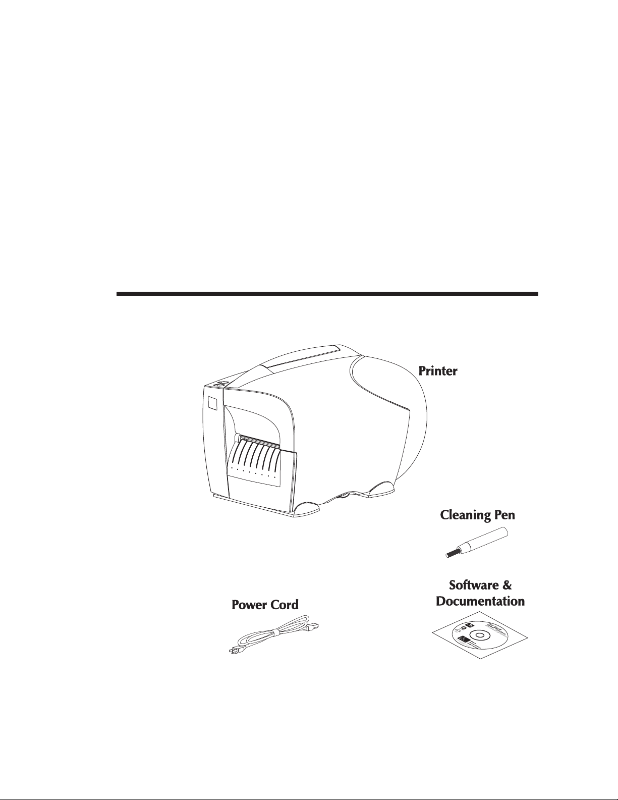
Unpacking Your
Printer
Open the shipping carton and remove the
printer and its accessories.
B
L
a
S
a
r
o
b
f
C
t
w
e
o
a
l
r
e
d
P
a
e
n
r
d
i
n
D
o
t
c
e
u
m
r
s
e
n
t
a
t
i
o
©2001 Zebra Technologies Corporation
105551-006
n
980342-001 Rev.A 1
Page 8
Installation & Operation
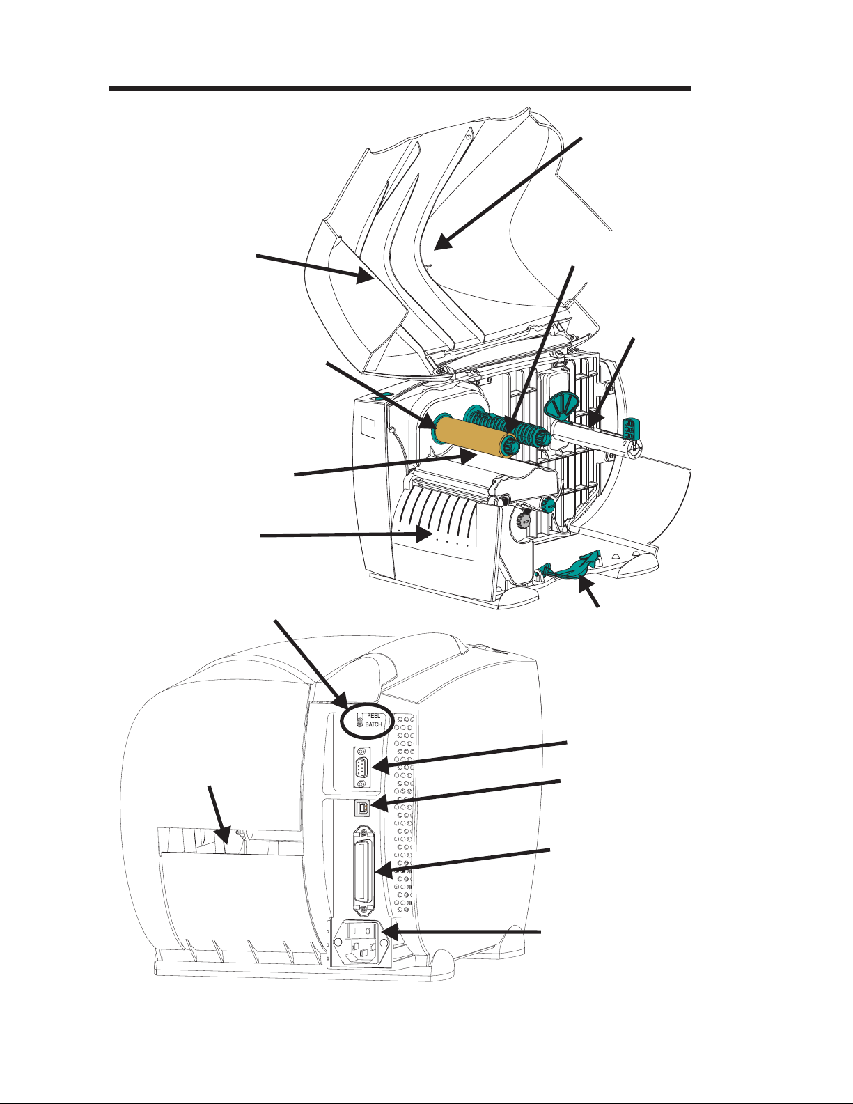
Getting To Know
Your Printer
Tear Edge
Ribbon Take-Up
Tube
Ribbon Core
(Shipped mounted on
Ribbon Tube)
Cover
(Open)
Ribbon Supply
Tube
Media Roll
Holder
Front Bezel
Label Mode
Switch
Auxiliary Media Access
(Opening for Fan Fold &
External Media)
Cover Latch
(Lift to Open)
Serial Interface
Connector
USB Interface
Connector
Parallel Interface
Connector
Power Switch and
Power Cord
Module
2 980342-001 Rev.A
Page 9
Installation & Operation
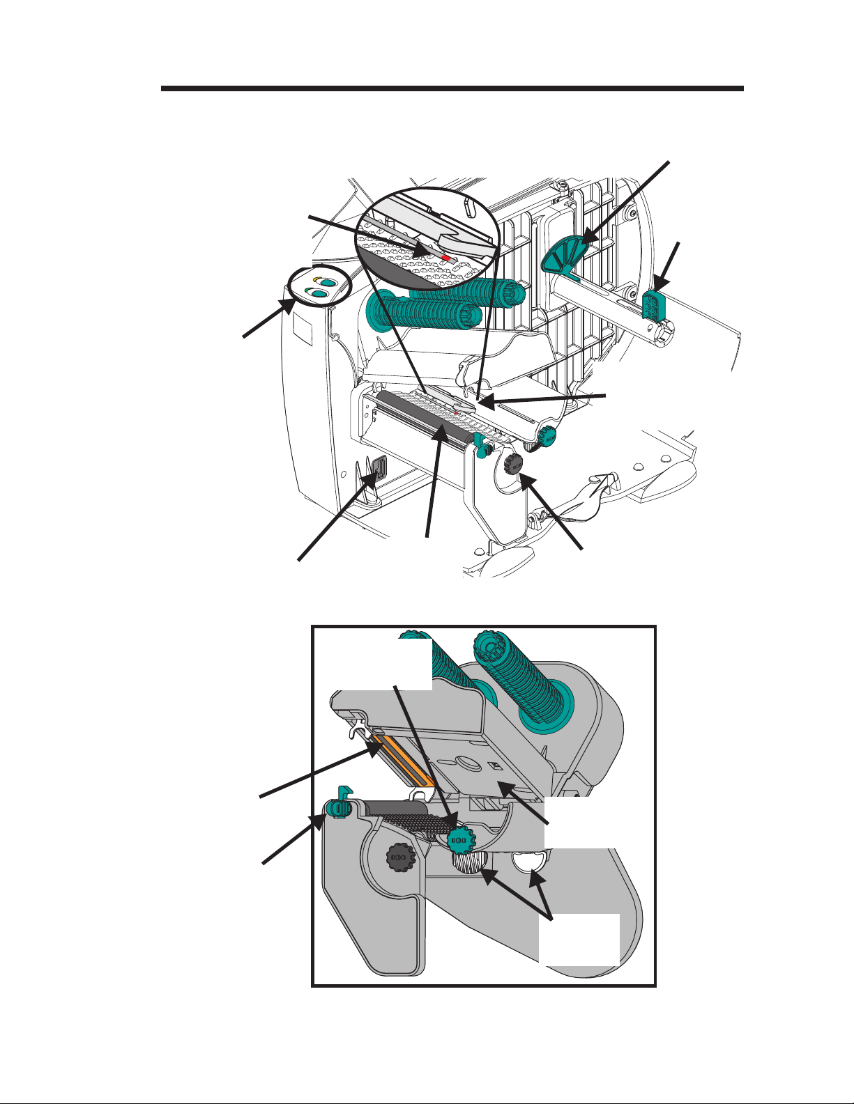
Getting To Know
Your Printer
Red Light
Position Indicator
(Position for Gap
Sensing Shown)
Controls
&
Indicators
Roll
Guide
Roll
Keeper
Transmissive
(Gap) Sensor
(Fixed Position)
Modular
Accessory Plug
Print
Head
Print Head
Release Lever
Platen
Roller
Media Guide
Adjustment
Reflective
(Blackline & Hole)
Sensor Adjustment
Ribbon Out
Sensor
Media
Guides
Print Mechanism
980342-001 Rev.A 3
Page 10

Installation & Operation
Controls &
Indicators
Button Function
Press Once - Halt batch printing.
PAUSE
Press Second Time - Resume batch
printing operation.
Press Once - Feed one label or “form”.
Feed
Button
Power
Indicator
Pause
Button
Error
Indicator
FEED
PAUSE &
FEED
Indicator LEDs
POWER
(Green)
On Solid OFF
Flashing OFF
OFF
OFF On Solid Hardware Error
OFF Flashing
On Solid On Solid
Press & Hold - Feed a single label, stop,
feed a single label, stop, and so on until the
FEED button is released.
Press & Hold a minimum of 3 seconds
to reset the printer.
ERROR
(Amber)
On Solid
Condition Report
Power On
Pause
Media/Ribbon Out
Head Open or Rewind Full
Data/Command Syntax Error
4 980342-001 Rev.A
Page 11
Controls &
Indicators
Installation & Operation
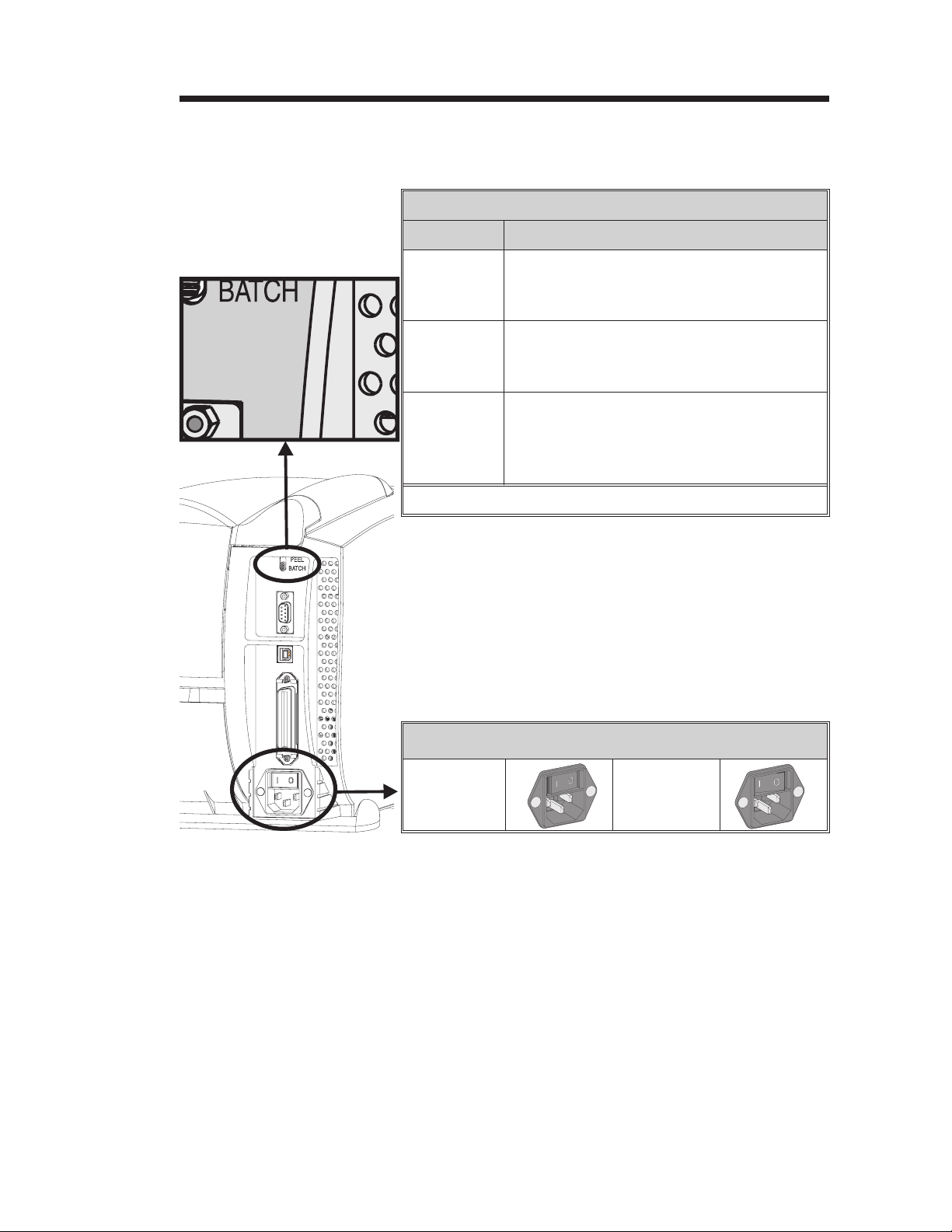
Label Mode Switch
Mode Description
Standard operation - Prints one or more
Batch
labels until the batch form (label) print op
eration is complete.
-
Peel with
Label Taken
Sensor
Peel with
out a Label
Taken
Sensor
Note: Reset the printer to initialize the mode change.
Print one label and pause. Remove label.
Prints next label. Repeats until print opera
tion is completed.
Print one label and pause. Remove label.
Press Feed to print next label. Repeat until
print operation is completed. (See EPL2 O
command with L parameter).
Power Switch
0 = OFF
(8 seconds
to power off)
1 = ON
-
980342-001 Rev.A 5
Page 12
Installation & Operation
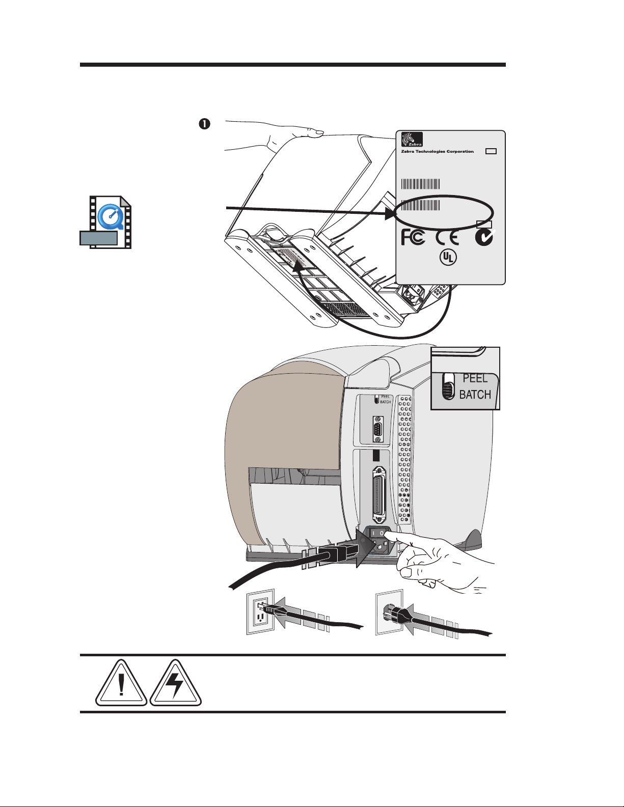
Installation The following steps will guide you through the
installation of the printer.
MOVIE
Step
Attach Power
Check
Printer
Voltage
Set Batch Mode
Pat. No.
5.813,343
6,068,415
EPL
TLP 2746
Model:
02/01/01
Mfg. Date:
Part Number:
Serial No.:
Input Power:
For home or office use
I
S
Part N
Hd-146
np
e
r
ut P
i
al
No
o
o
.:12
we
.:
r
XX
:1
0
XXX
15
X
XXX
V
A
X
C
XX
X
6.3
X
A
50
/6
0H
z
I.T.E.
8T34
2746-120XXX-001
12345678912
115-230 VAC,2-1 Amps, 50/60 Hz
C
®
US
MADE IN USA
with foreign and domestic parts
N2557
Batch Mode
Set Printer
Power OFF
(OFF = 0)
Attach the
Power Cord
See Warnings - Page v
6 980342-001 Rev.A
Page 13
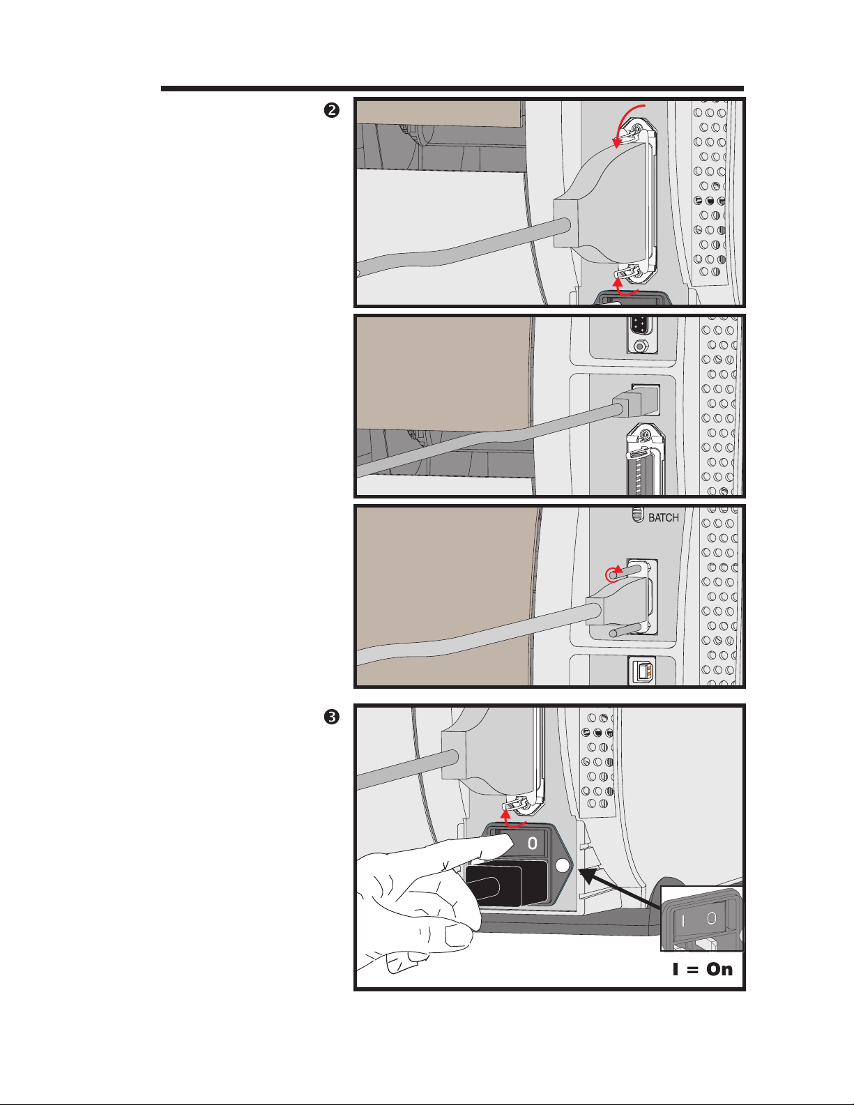
Step
Attach Interface
Cable
Parallel
Interface
Installation & Operation
USB
Interface
Serial
Interface
Step
Apply Power
980342-001 Rev.A 7
Page 14
Installation & Operation
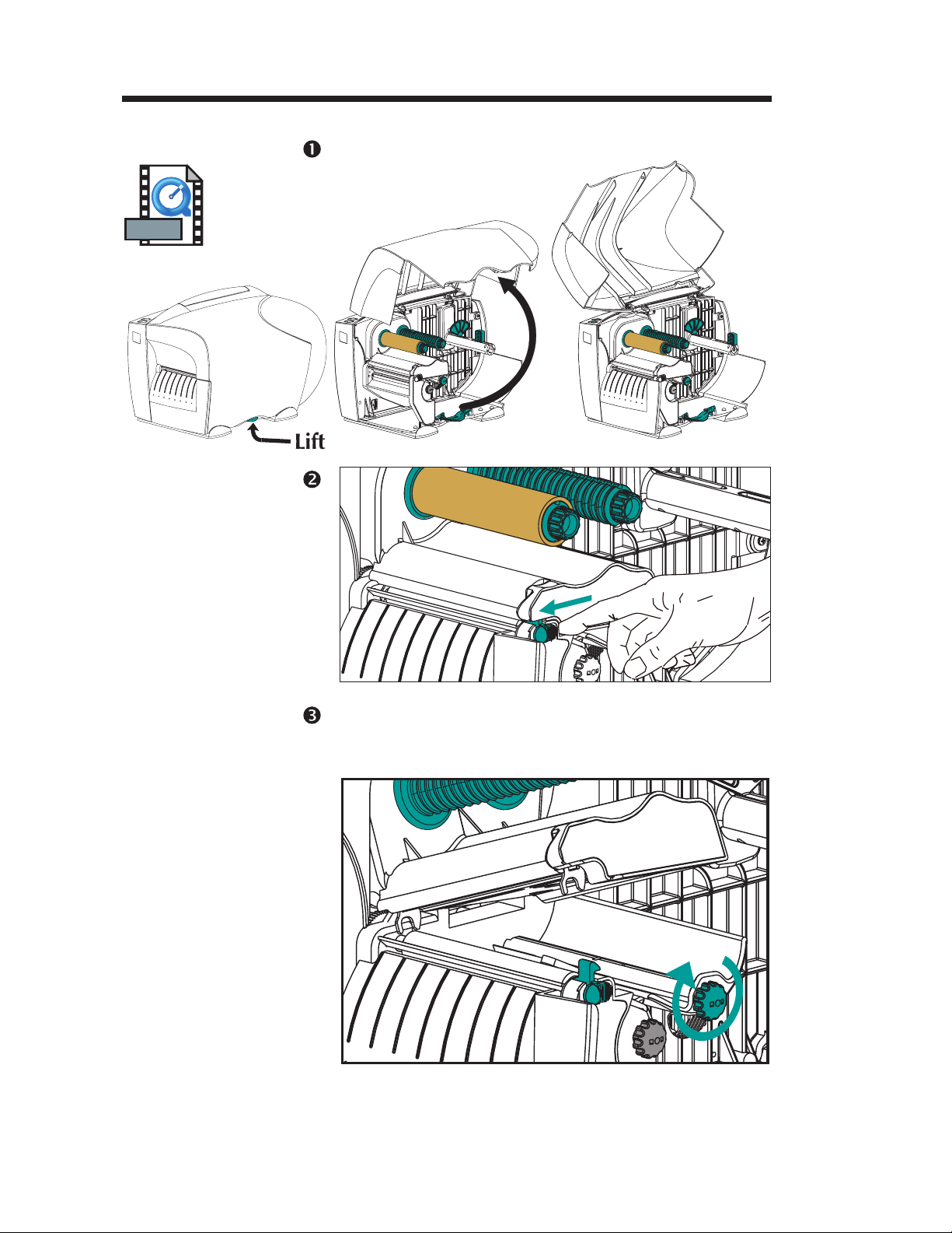
Media Loading
MOVIE
Print Head
Step
Step
Open the
Open the cover. Lift the green latch to unlock
the cover.
Step Turn the green adjustment knob clockwise to
Open the
Media Guides
open. Verify the media sensor indicator light is
directly under the transmissive sensor.
8 980342-001 Rev.A
Page 15
Installation & Operation
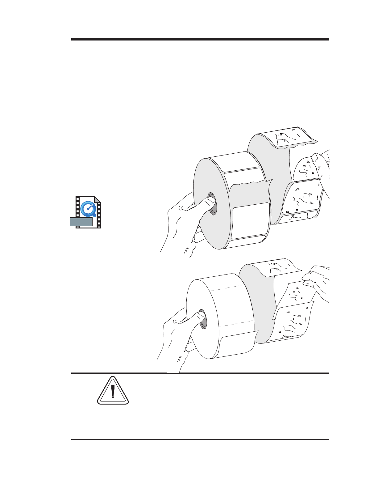
Before You Load
Media in the
Printer
Remove all labels
that are held by
adhesives or tape
MOVIE
Labels
You must remove the outside length of media
(that is, one, full revolution of labels and any
liner). When you remove this part of the me
dia, you remove the oils, dust, and adhesives
that contaminate it. Tape or adhesive holds the
loose end and the outside length of media
becomes contaminated when handled or
stored.
-
Tag Stock
Detach both ends of
the bottom tag
You must avoid dragging adhesive or dirty
media between the print head and platen. Such
an occurrence damages the print head and is
not covered under your warranty. Using clean
media prevents damage and reduces wear on
the print head and platen.
980342-001 Rev.A 9
Page 16
Installation & Operation
Media Loading
Open
Roll
Guide
Open
Keeper
Insert Roll
Load the media roll - 1 inch inner diameter.
Step
Close
Keeper
Hold the
Printer
and
Push the
Keeper
Tight
Against
the Roll
10 980342-001 Rev.A
Page 17
Open
Roll Guide
Insert Roll
Lift Roll
Over
Keeper
Installation & Operation
Step Load the media roll - 3 inch inner diameter.
Set Roll On
Holder
Between
Roll Guide
and Keeper
Hold the
Printer
and
Push the
Keeper
Tight
Against
the Roll
980342-001 Rev.A 11
Page 18
Installation & Operation
Media Loading
Step
Thread Media
Thread the media between the media guide
and platen assembly. Center media over the
platen roller and under the media sensor.
Center Media
12 980342-001 Rev.A
Page 19
Step Note the media orientation for the different
Outside Wound
Installation & Operation
media delivery methods.
Inside Wound
Fan Fold
980342-001 Rev.A 13
Page 20
Installation & Operation
Media Loading
Step
Pull Media Taut
Adjust
Media Guides to
Media Width
Step Close the print head.
Adjust media guides to match the media width.
Turn the adjustment knob clockwise to narrow
the guides.
Close
Print Head
Step Press the Feed button once (with the power ap
Power ON
Labels Loaded
Press FEED
-
plied and the power switch “ON”).
14 980342-001 Rev.A
Page 21
Installation & Operation
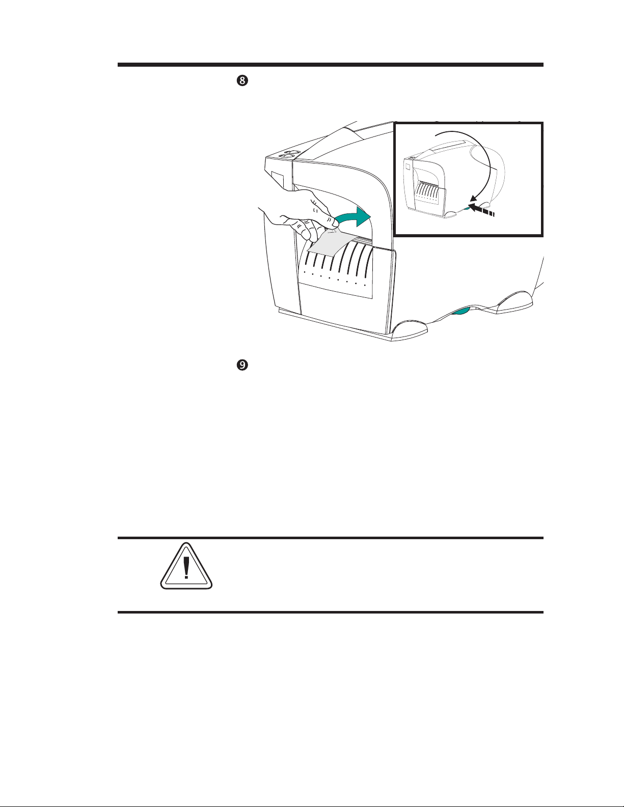
Step Close the cover. Remove excess media. Use the
tear edge in the cover, directly above the me
dia.
Close
Cover
-
Remove
Push
Excess
Media
Step Set label detection parameters for media:
· Use the AutoSense procedure (page 16) for
first time use of new media to set transmissive
(gap) sensor.
· Use the AutoSense procedure for detection
of label and gap lengths.
· Use programming to set continuous media
mode. See the Q command in the EPL2 pro
grammer's manual for details.
-
DO NOT turn the power switch OFF (0) while
reloading media or data loss may result. Load
new media and press the FEED button to
automatically resume printing.
980342-001 Rev.A 15
Page 22
Installation & Operation
Using AutoSense AutoSense sets the sensitivity of the
transmissive (gap) sensor, measures and stores
the form (label) and gap lengths. For more
details on media sensing and sensors see page
65. To activate the AutoSense feature:
MOVIE
Load Labels
Visually Verify
Reflective Sensor
Step Load labels into the printer. Verify that the re
flective sensor’s location (red light) is under the
transmissive sensor for label mode operations.
Position
Step Turn OFF printer power. Set Batch mode.
Do not use the peel mode.
-
Batch Mode
0
Power OFF
0
16 980342-001 Rev.A
Page 23
Installation & Operation
Step Press and hold the FEED button while turning
ON printer power.
Press and
Hold the
FEED Button
Power ON
Step Release the FEED button when the power
indicator begins to flash and the label will begin
to advance.
Release the
FEED Button
980342-001 Rev.A 17
Page 24
Installation & Operation
Step The printer will advance 3-4 labels while per
forming the sensor adjustment. When the
adjustment is complete, a status summary label
will be printed and the printer will be placed in
Diagnostic Dump mode.
P
M
U
D
n
i
w
3
o
1
n
2
6
N
1
3
U
0
1
D
,
T
:
1
5
Z
n
3
o
0
i
2
t
0
1
p
0
Q
,
O
2
2
3
3
l
0
8
v
R
0
a
q
2
K
1
Y
3
l
r
D
9
v
5
8
a
1
0
S
0
,
l
K
0
v
K
3
,
a
0
9
0
,
0
5
K
8
0
0
4
I
:
,
.
K
1
m
0
6
e
K
0
0
5
,
m
0
4
:
K
E
2
0
:
m
,
e
e
0
z
0
i
m
s
0
G
:
r
e
m
f
f
e
u
m
1
b
,
F
8
e
,
g
N
a
,
6
m
I
9
:
1
0
t
.
r
4
o
0
p
.
l
4
a
i
r
7
e
3
S
2
s
I
"
4
Sample: DUMP Mode
Printout
4" Is-237 4.04.01
Serial port : 96,N,8,1
Image buffer size:245K
Fmem:000,0K,061.4K avl
Gmem:000K,0593K avl
E
mem:000K,0593K avl
I8,0,001 rY
S8 D12 R032,000 ZT UN
q0832 Q1235,036
Option:D
11 12 13
now in DUMP
-
Step Press the FEED button to exit the Dump mode.
Remove excess labels.
Press FEED
Prints:
out of DUMP
outof DUMP
18 980342-001 Rev.A
Page 25
Installation & Operation
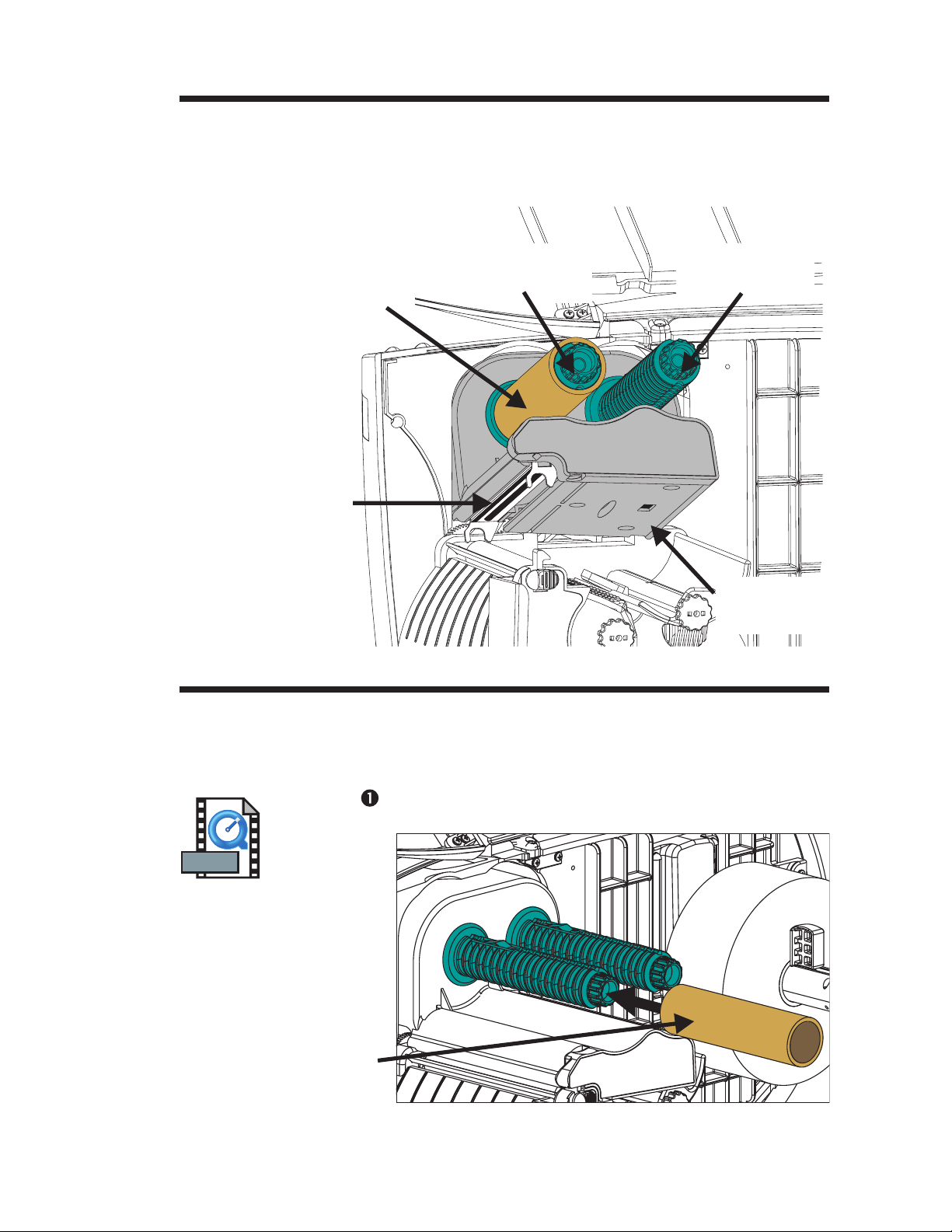
Thermal Transfer
Printer Features
Ribbon Core
(Shipped mounted on
Ribbon Tube)
Print Head
The thermal transfer printer supports wax,
resin, and wax resin ribbons in 1 inch
(24.5mm) inner (nominal) and 2.53 inch
(64mm) maximum outer diameters.
Ribbon Take-Up
Tube
Ribbon Supply
Tube
Loading Transfer
Ribbon
Step Insert an empty ribbon core on the ribbon
MOVIE
Insert Ribbon Core
Ribbon Out
Sensor
Refer to the following instructions for installation of the ribbon.
take-up tube.
Ribbon
Core
980342-001 Rev.A 19
Page 26
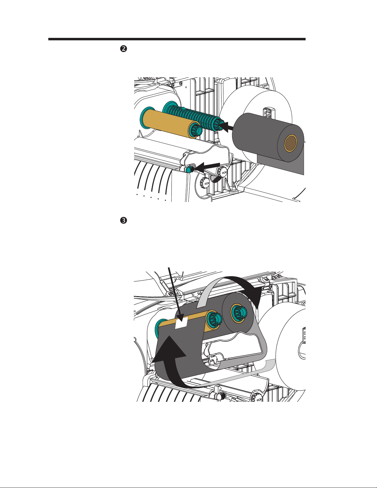
Installation & Operation
Step Insert a transfer ribbon roll on the ribbon supply
Insert Ribbon Roll
Open Print Head
tube. The transfer ribbon unwinds clockwise.
Open the print head.
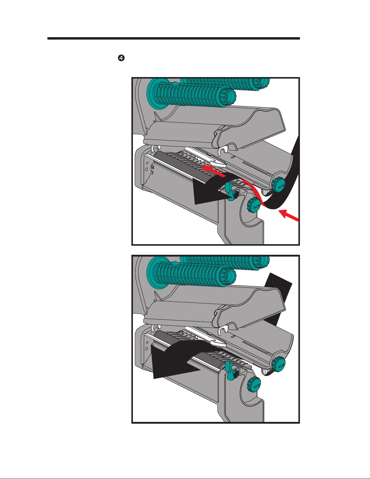
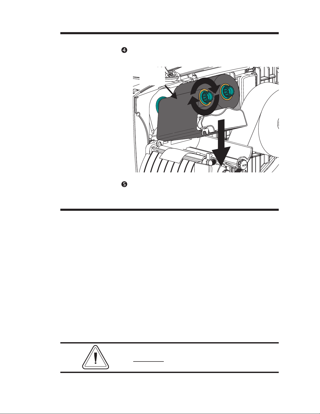
Step Thread the transfer ribbon under the print head
Thread Ribbon
Attach Ribbon to
Ribbon Core
assembly and clockwise around the ribbon
core and take-up tube. Attach the ribbon to the
core.
Tape
20 980342-001 Rev.A
Page 27
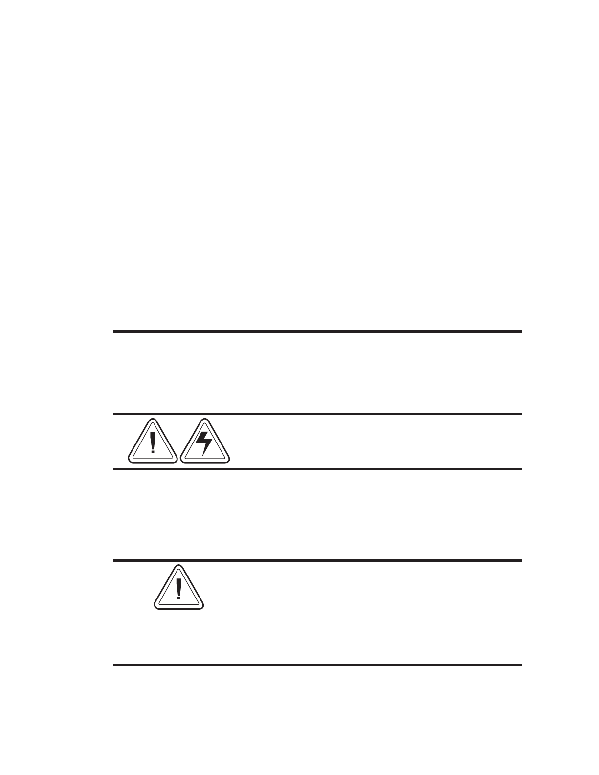
Installation & Operation
Loading Transfer
Ribbon - Step
Turn Ribbon
Take-Up Tube
Close Print Head
Close the Printer
Step With printer power ON and media loaded,
Turn the ribbon take-up tube clockwise a mini
mum of two (2) times to lock the ribbon on the
core.
Ribbon
Core
press the FEED button until approximately 6
inches or 150 mm of media has advanced.
-
Configuring
Thermal Transfer
Printing
By default, the thermal transfer printer is set to
the direct thermal print mode as configured
"Out of the Box". The printer will print thermal
transfer media in direct thermal mode, but it
will not sense a ribbon out media condition.
The most common method of changing the
print mode is to use the Windows printer driver.
Select the Ht-146 printer and print a label.
To configure thermal transfer printing with pro
gramming, use the O (thermal transfer) and
OD (direct thermal) commands. The print
mode will be set until changed by program
ming.
See the EPL2 programmer's manual for
important
details on printer programming and
printing using the Option (O) command.
-
-
980342-001 Rev.A 21
Page 28

Installation & Operation
22 980342-001 Rev.A
Page 29
Operator Maintenance
2
Operator Maintenance
This section provides information on operator
maintenance procedures for your printer.
Cleaning Your
Printer
The printer’s media path allows for cleaning
and clearing of media jams. The user can clean
the print head, platen roller and areas adjacent
to the media path surfaces.
Warning -Shock Hazard - See page v.
Always turn the printer off before cleaning.
The media path surfaces (except the print
head) can be cleaned with a lint free, clean,
damp cloth very lightly moistened with medical
grade alcohol. Alcohol may be used to help re
move any adhesive or label material buildup.
If a label has become jammed in the printer,
remove the label and any adhesive residue,
immediately. Adhesive may spread through out
the printer’s media path if not completely
removed. Many adhesives are permanent and
have short “set” times.
-
980342-001 Rev.A 23
Page 30
Operator Maintenance
Extending Print
Head Life
The print head is the most critical component in
your printer, and possibly the most delicate. It
is a consumable item just like the brakes on
your car, which will eventually wear over time.
However, with ongoing careful attention and
maintenance, you can extend the life of the
print head!
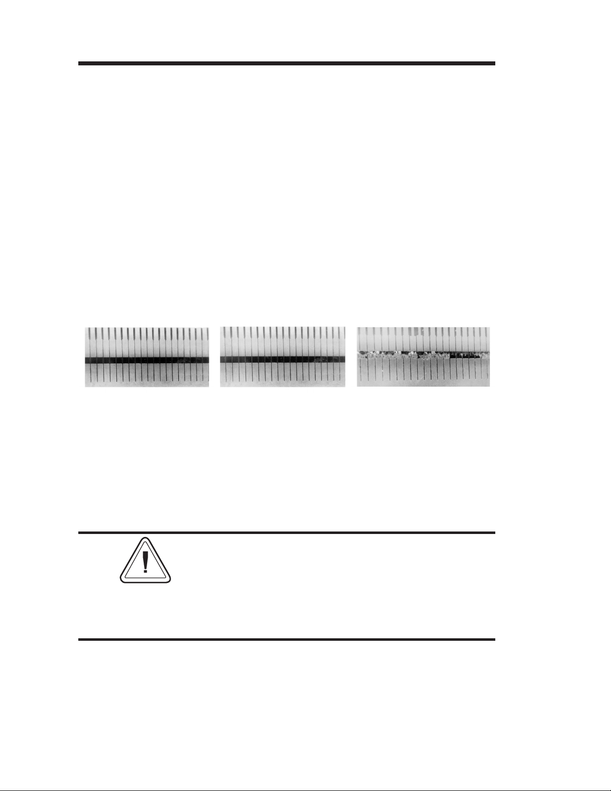
Below are photographs of three print heads.
The first print head is brand new. The second
has printed over 1 million linear inches of ther
mal transfer labels and has been properly main
tained. The third print head has printed far
fewer labels, but without proper care and main
tenance, signs of abrasion and contamination
build-up are evident.
-
-
-
New Over 1 Million Less Than 1 Million
Inches Inches
(Properly Maintained) (Without Proper Care)
Contaminant buildup occurs gradually and results in poor print quality that may look like
faded print or failed print element(s). This build
up is very resistant to cleaning with the
pre-soaked swabs and is difficult to remove.
Note - The one million inches of print head
usage shown in the illustration above is used for
reference only. The actual print head life will
vary due to enviromental conditions, printer
setup and the properties of the media used. See
Print Head Care for more details.
24 980342-001 Rev.A
Page 31

Operator Maintenance
Print Head Care The main factors that contribute to reduced
head life are:
Touching the print head! Static electricity
·
can discharge and damage the print head.
The body's oils and acids also damage the
print head.
Cleaning - For optimum performance,
·
clean the print head regularly after every roll
of thermal transfer ribbon or after every roll of
direct thermal labels.
Abrasion - Over time, the movement of me
·
dia/ribbon across the print head will wear
through the protective ceramic coating, ex
posing and eventually damaging the print el
ements (dots).
-
-
-
· Use of proper media - Use only approved
Zebra Technologies Corportation media.
Non-approved media may contain
chemicals that can destroy or dramatically
reduce the print head's life. Approved
thermal transfer ribbons have a special
anti-stick back coating that helps to dissipate
static and provide lubrication.
· Ribbon Width - Ensure that the thermal
transfer ribbon is as wide or wider than the la
bel media to prevent exposing the elements
to the more abrasive label material.
·
Temperature - Print head density (heat) set
ting. Set the density to the lowest possible set
ting that prints a good image.
·
Print Speed - Fast print speeds have higher
friction levels on the print head's surface.
-
-
-
·
Regular Print Head Conditioning - Use
our Save-a-Print head cleaning film to re
move print head contamination buildup
quickly and easily. (Part No.105950-047)
980342-001 Rev.A 25
-
Page 32

Operator Maintenance
MOVIE
Cleaning the
Print Head
Step Open the printer and the print head carriage.
As you use your printer, the print head may be
come contaminated resulting in poor print
quality. Whenever new labels are loaded into
the printer, the print head should be cleaned
with a cleaning pen.
Warning - Static Discharge - See page v.
Never touch the print head. Always clean the
print head with a cleaning pen (to protect the
print head from static discharge and fibers).
-
Print
Head
Cleaning
Pen
Don’t use the cleaning
pen for cleaning other
printer surfaces
Step Gently rub the cleaning pen across the surface
of the print head. Clean the black surface to
wards the front edge of the print head.
Allow the print head to dry for 1 minute before
loading labels.
Do Not Clean the Print Head with sharp
objects! Only used approved cleaning
materials.
-
26 980342-001 Rev.A
Page 33

Operator Maintenance
Platen Cleaning Liner-free platen printers require periodic
cleaning. Adhesive and particles can build up
and cause the media to stick.
The standard printer platen does not normally
require cleaning. Normal operation leaves label
liner particles which is normal. Clean the platen
only to remove adhesive (or other contami
nates).
Step Open the print head and remove the media.
Step Place a cleaning card on the platen (and all of
lower print mechanism).
-
Cleaning
Card
Step Press the FEED button and the media will feed.
Repeat until the cleaning card has ejected from
the front. If the card stops feeding with a media
out error, press the PAUSE and then the FEED
button to clear the error. Press the FEED but
ton. Repeat button sequence as necessary.
Step Repeat steps 2 and 3 until the platen is clean.
Do not re-use cleaning cards.
-
980342-001 Rev.A 27
Page 34

Operator Maintenance
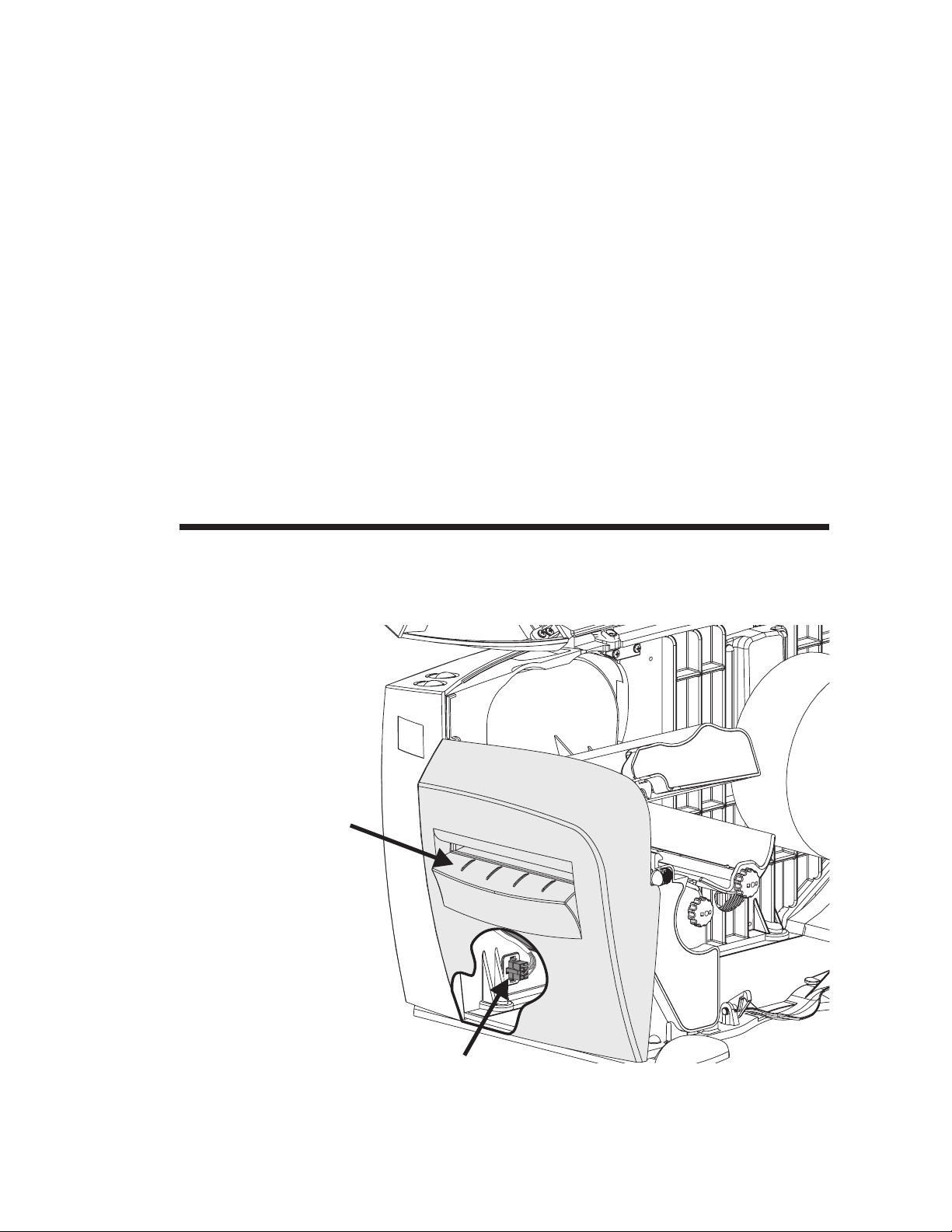
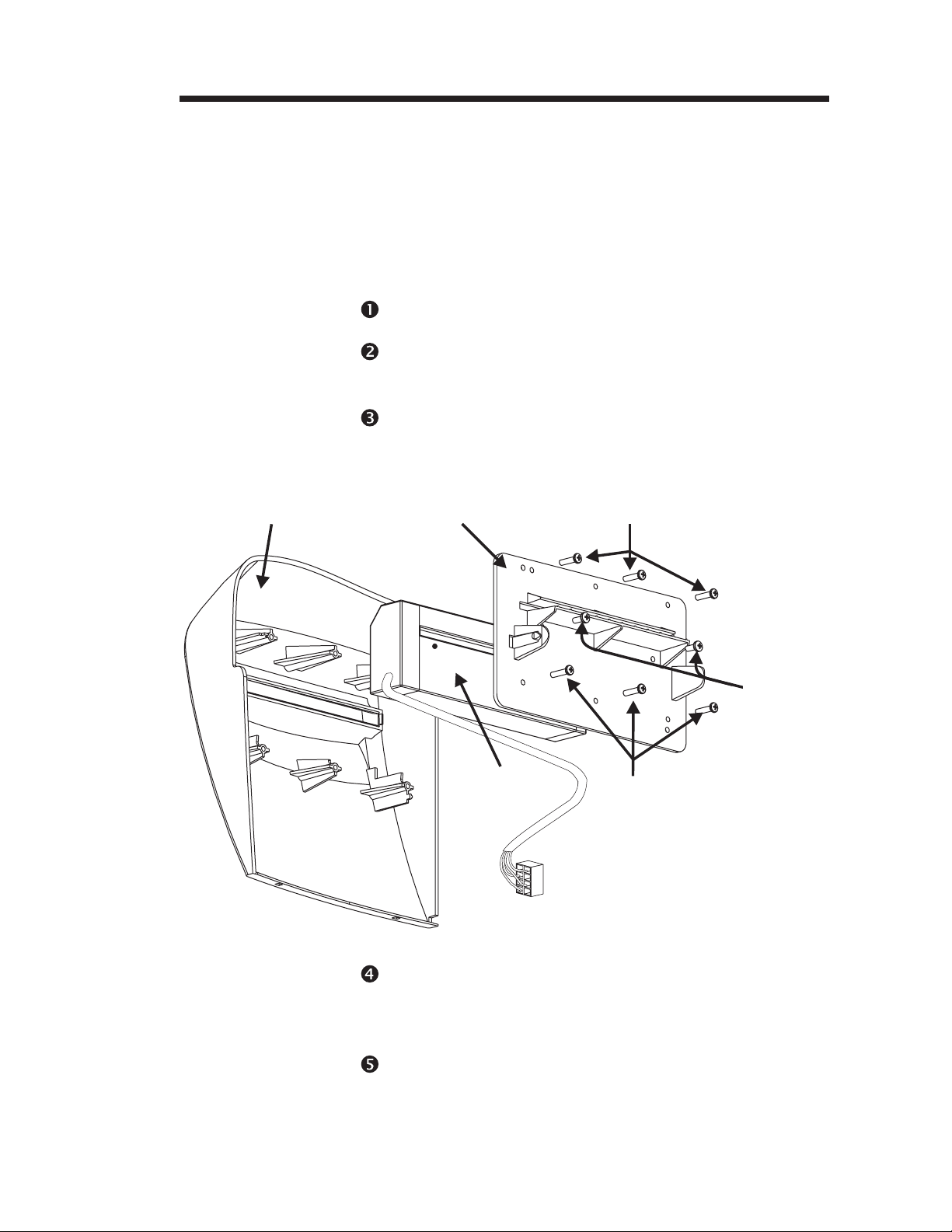
Front Bezel Access The printer’s front bezel is designed for easy re
moval and replacement. Some printer mainte
nance operations are facilitated by the removal
of the front bezel.
Standard
Front Bezel
-
-
Inside of
Front Bezel
Bezel Guide Tabs in Slots
The front bezel should be installed for normal
print operations. The front bezel helps to keep
the printer clean. Some printer options
supercede the use of the standard front bezel.
Bezel
Retaining Tabs
Bezel Guide Slots
28 980342-001 Rev.A
Page 35

Operator Maintenance
MOVIE
Front Bezel
Removal
Step Open cover.
Step Slide the blade of the screwdriver between the
Pry Bezel
Arm Open with
Screwdriver
Swing Bezel
Down and Off
The front bezel can be easily removed with a
small blade screwdriver.
front bezel’s retaining tab arm and the inside
wall of the lower print mechanism.
While gently pulling on the top right corner of
the front bezel, gently pry the tab away from
the inside wall of the print mechanism.
980342-001 Rev.A 29
Page 36

Operator Maintenance
MOVIE
Replacing the
Front Bezel
Bezel
Retaining Slots
Step Align the bezel guide slots to the bezel guide
To replace the bezel, simply snap it onto the
printer.
Bezel
Guide Tabs
tabs on the bottom of the printer.
Insert Bezel Guide
Slot onto Tabs
Snap Retainer Tabs
into Retainer Slots
Step 2 Swing the bezel up while pivoting on the guide
tabs and into the print mechanism. The bezel
will snap in place with a gentle push. The re
tainer tabs will lock the bezel in place at the
print mechanism’s retainer slots.
-
30 980342-001 Rev.A
Page 37

Using the Label Dispense Option
3
Using the Label Dispense Option
This section provides information on the
printer’s Automatic Label Peel and Print option.
Label Dispense
Features
Peel Bar
Pinch
Roller
The printer can dispense a single peeled label
in the Label Dispense (Peel) mode. Removing
the presented label will prompt the printer to
print the next label.
Label Dispense
Bezel
980342-001 Rev.A 31
Modular Accessory
Socket and Plug
Label Taken
Sensor
Page 38

Using the Label Dispense Option
Label Dispenser
Mounting
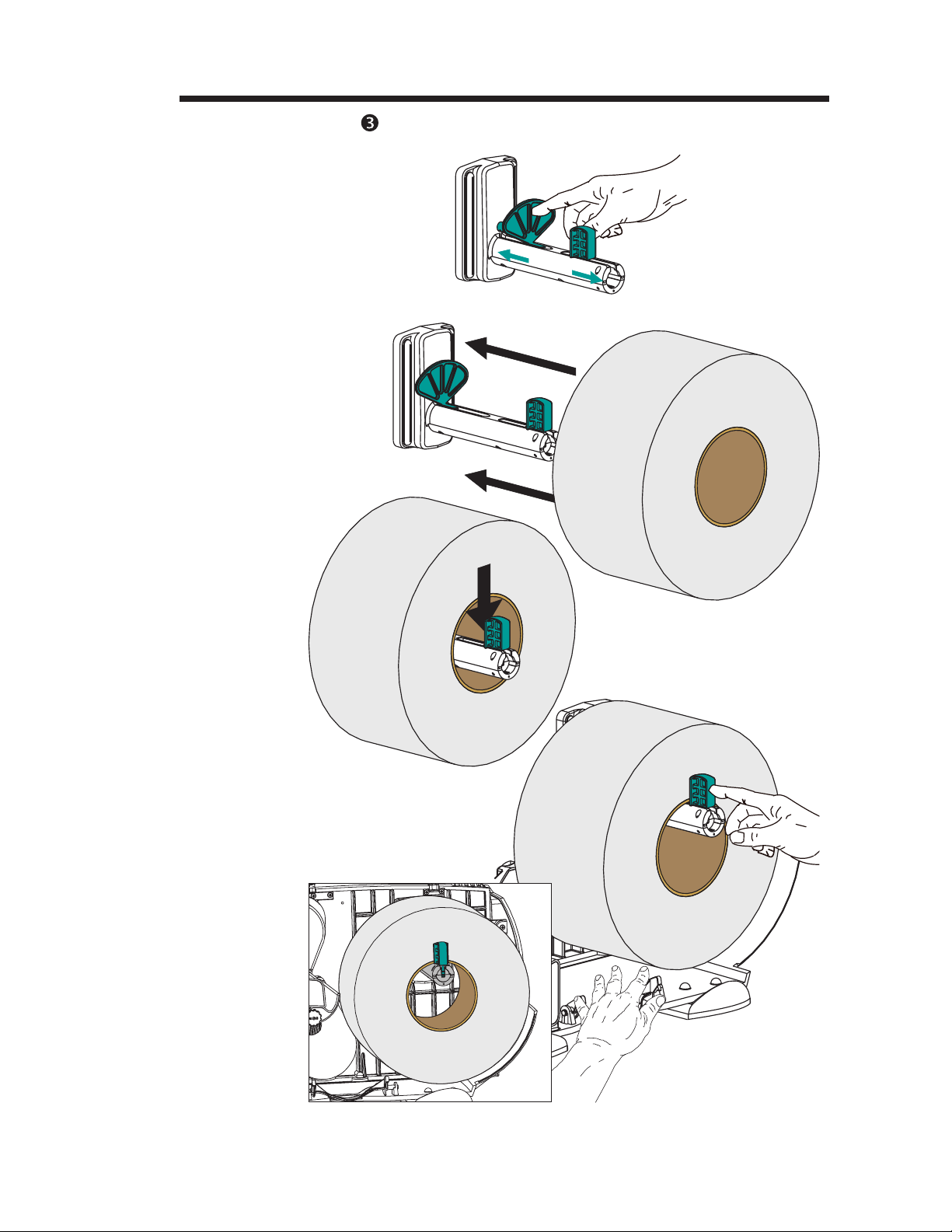
Step Turn the power off. Open the cover. Remove
MOVIE
Step Open the print head. Insert the right side of the
Print Head
Right Side of
Peel Bar
The label dispenser is mounted in place of the
front bezel.
the bezel, see “Front Bezel Removal”, page 29.
peel bar into the print mechanism’s right peel
bar mounting slot. Note that the left side has the
beveled tab.
Open
Insert
Peel Bar
Mounting
Slot
Insert
Left Side of
Peel Bar
Swing the left side of the peel bar’s tab into the
peel bar guide channel and down into the left
mounting slot.
32 980342-001 Rev.A
Page 39
Using the Label Dispense Option
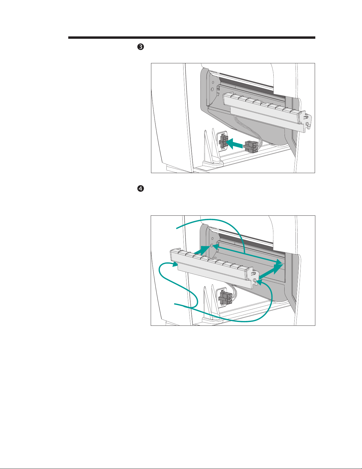
Step Connect the label dispenser’s (accessory) cable
plug into the accessory socket.
Plug-in Label
Dispenser
Step Slide the left tab of the label dispenser into the
left slot on the print mechanism. Swing the right
tab into the right slot.
Insert Label
Dispenser
Slots
Tabs
980342-001 Rev.A 33
Page 40

Using the Label Dispense Option
Label Dispenser
Mounting
Step
Open
Label
Dispenser
Pull the label dispenser door open.
Slide the label dispenser’s cable into the slot immediately under the left end of the label dispenser.
Insert Cable
in the Slot
Pull Cable
Taut
Pull the cable gently down to remove slack
from the under side of the open label dispenser.
34 980342-001 Rev.A
Page 41
Using the Label Dispense Option
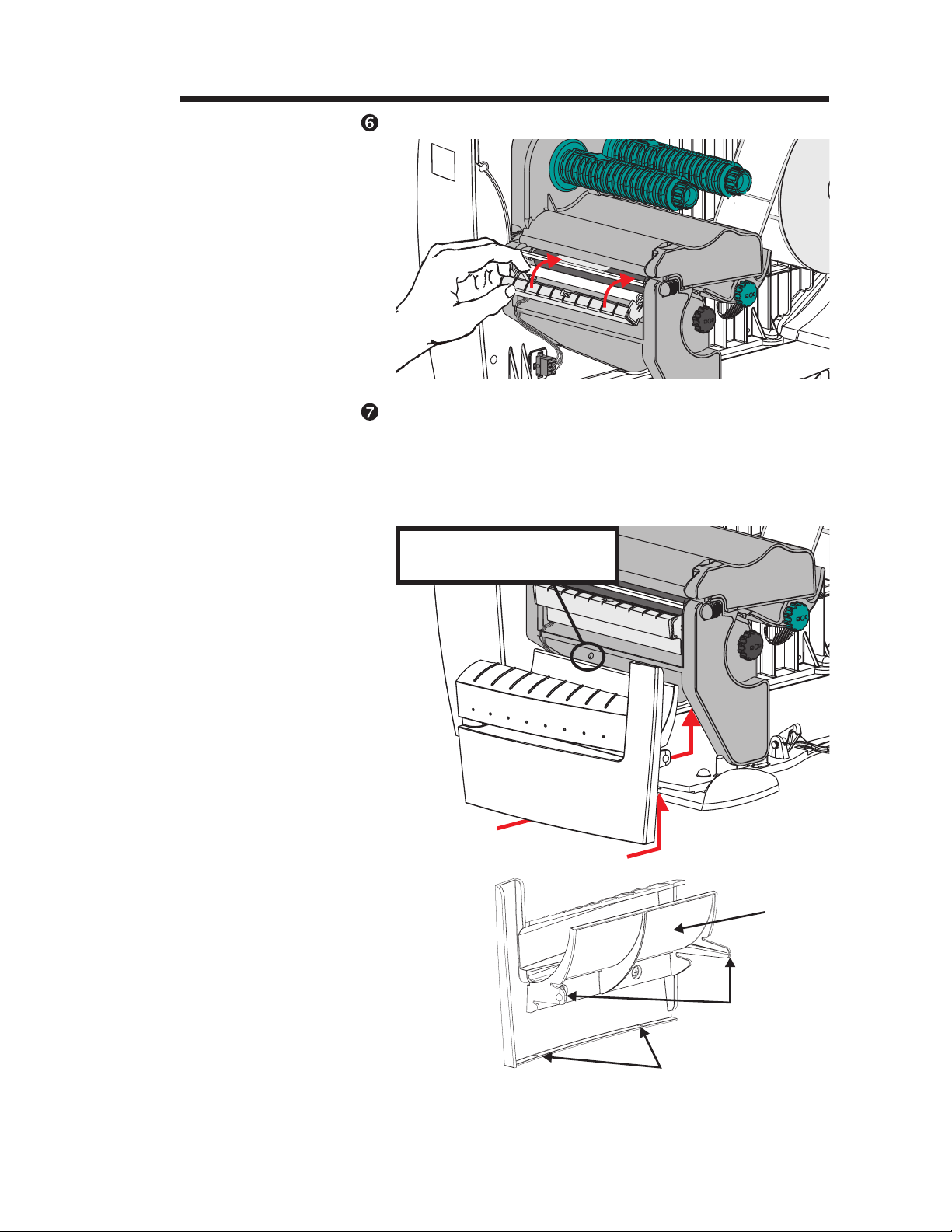
Step Close the label dispenser.
Step Insert the liner guide (on the inside of the label
dispenser bezel) into the area below the print
mechanism. Insert the bezel guide slots onto
the guide tabs on the bottom of the printer, see
page 29. Slide the bezel up to snap it in place.
Insert Bezel Guide
Slot onto Tabs
Snap Retainer Tabs
into Retainer Slots
Label Dispenser Bezel
Retainer Slot
(both sides)
Liner
Guide
Retaining
Tabs
Guide Slots
980342-001 Rev.A 35
Page 42

Using the Label Dispense Option
Using Label
Dispense
Step Open the cover.
Power ON
Labels Loaded
The printer can dispense a single peeled label
without the liner in the “Automatic” Label Dis
pense (Peel) mode. Removing the presented la
bel will prompt the printer to print the next
label.
Load and set label parameters (via AutoSense
or programmed with the Q command).
-
-
Press FEED
Step Press the FEED button until approximately 8
inches (20 cm) of media has exited the printer.
Step Remove the exposed labels from the media
liner (backing).
Peel
Exposed
Labels
36 980342-001 Rev.A
Page 43
Using the Label Dispense Option
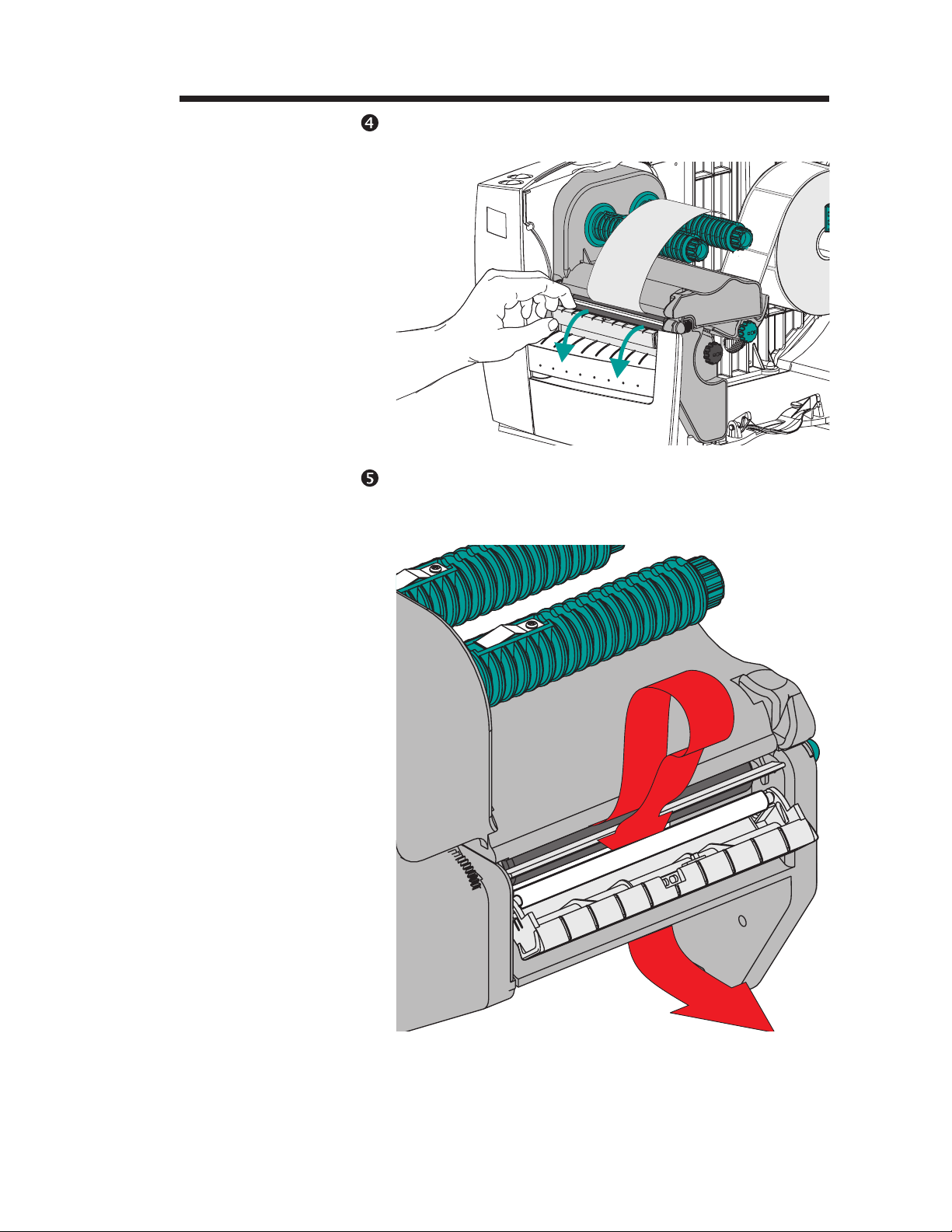
Step Swing the label dispenser down to open.
Open the
Label
Dispenser
Step Thread the media liner (backing) below the
platen roller and above the pinch roller into the
liner slot.
Thread Media Liner
(Label Dispenser Bezel
Not shown)
980342-001 Rev.A 37
Page 44

Using the Label Dispense Option
Using Label
Dispense - Step
Thread the
Pull the
Liner Taut
Liner
Pull the liner taut and close the label dispenser.
The label dispenser will snap
into place.
Close Label
Dispenser
38 980342-001 Rev.A
Page 45

Step Change the printer mode switch to the “Peel”
MOVIE
Switch to Peel Mode
Remove Liner Slack
(Press FEED)
Using the Label Dispense Option
position at the rear of the printer. Reset the
printer or cycle the power.
Remove Label
Step Press the FEED button to remove liner slack
Step Close and latch the printer's cover.
Close Printer
Printer is Ready to
Dispense Labels
and peel a label from the liner backing. Remove the peeled label.
980342-001 Rev.A 39
Page 46

Using the Label Dispense Option
Label Dispenser
Removal
Step Disconnect the label dispenser plug. Press the
Step Open the label dispenser.
Step While holding the label dispenser in the open
Pinch, Hold
and
Lift Up to
Remove
Label
Dispenser
The label dispenser is designed for easy re
moval for cleaning and reconfiguration.
release and pull it out of the socket.
position on the right side, push the dispenser
from the bottom with a gentle steady pressure
to pop it off.
-
40 980342-001 Rev.A
Page 47

Using the Label Dispense Option
Peel Bar Removal The peel bar is easily removed without tools.
Using tools is not recommended. Personnel in
jury or damage to the printer could result from
using screwdrivers or other sharp objects to
wedge the bar out.
Step Open the print head.
-
Step Remove the bezel (see page 29) or label dis
Step Push the peel bar into the right side of print
Push the Peel Bar
to the Right
Swing the Peel Bar
Up and Out
penser (32), if present, to allow easier access to
the bottom of the peel bar.
mechanism and swing the bar up and out of the
bar’s guide slot. Hold the printer down with the
other hand. The peel bar may need some gentle downward pressure to slightly bend bar up
to slip the left end past the lip.
980342-001 Rev.A 41
Page 48

Using the Label Dispense Option
Printing with the
Label Dispenser
The printer can be programmed to print single
or multiples of a single label (form). Parameter
fields in the printer’s Print (P and PA) com
mands control the print quantity of a single
form (or job).
The P command can interact with the Counter
(C) command to make sequencing data fields
for serialization of labels. The printer also sup
ports printing multiples of a single number and
then sequencing the number. See the Page
Mode (EPL2) programmer’s for details.
The software controlling the printer may finish
printing with the printer storing the last label in
buffer memory. The printer will print the first
label and wait for it to be removed before allowing the second label to print.
-
-
42 980342-001 Rev.A
Page 49

Using the Liner Take-Up Option
4
Using the Liner Take-Up Option
This section provides information on the
printer’s liner take-up option.
Liner Take-Up
Features
Label Dispenser &
Sensor Assembly
The liner take-up option supports liner take-up
in Label Dispense (Peel) mode. The printer can
wind the label liner and present peeled labels
with or without the label dispenser option. Label dispensing without the label dispenser option must programmed into the printer with the
O,L command. This configuration uses the
FEED button to initiate printing.
Liner Take-Up
Tube
Media
Clip
Media Full
Sensor
980342-001 Rev.A 43
Page 50

Using the Liner Take-Up Option
Liner Take-Up
with Automatic
Label Dispense
MOVIE
The printer with the liner take-up mechanism
and the label dispenser option can dispense a
single peeled label and wind the backing in the
Dispense (Peel) mode. Removing the pre
sented label will prompt the printer to print the
next label.
Liner Take-Up Capacity - The quantity of
media liner wound will vary due to
environmental conditions and liner properties.
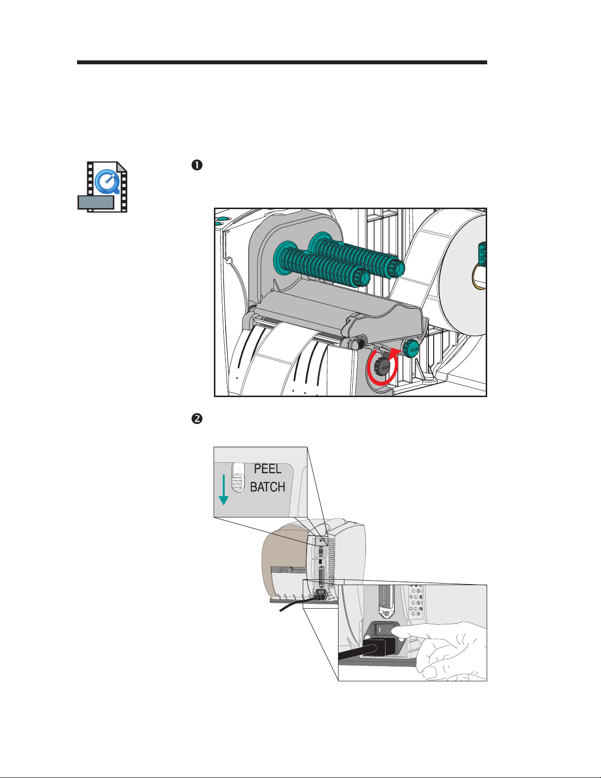
Step Open the printer cover. Remove front bezel, if
present. See Front Bezel Removal, page 29.
Step Load media and set media parameters (via
AutoSense, see page 16, or programming with
the Q command) in the printer.
StepStep Press the FEED button until approximately 16
inches (40 cm) of media has exited the printer.
-
Remove
Front Bezel
Load Media
FEED Labels
44 980342-001 Rev.A
Page 51

Using the Liner Take-Up Option
Liner Take-Up
Step
Peel Exposed Labels
Step Open the label dispenser door. Thread the me-
Remove the exposed labels from the media
liner (backing).
dia liner (backing) below the platen roller into
the liner slot.
Open the
Label Dispenser
Thread the Liner
980342-001 Rev.A 45
Page 52

Using the Liner Take-Up Option
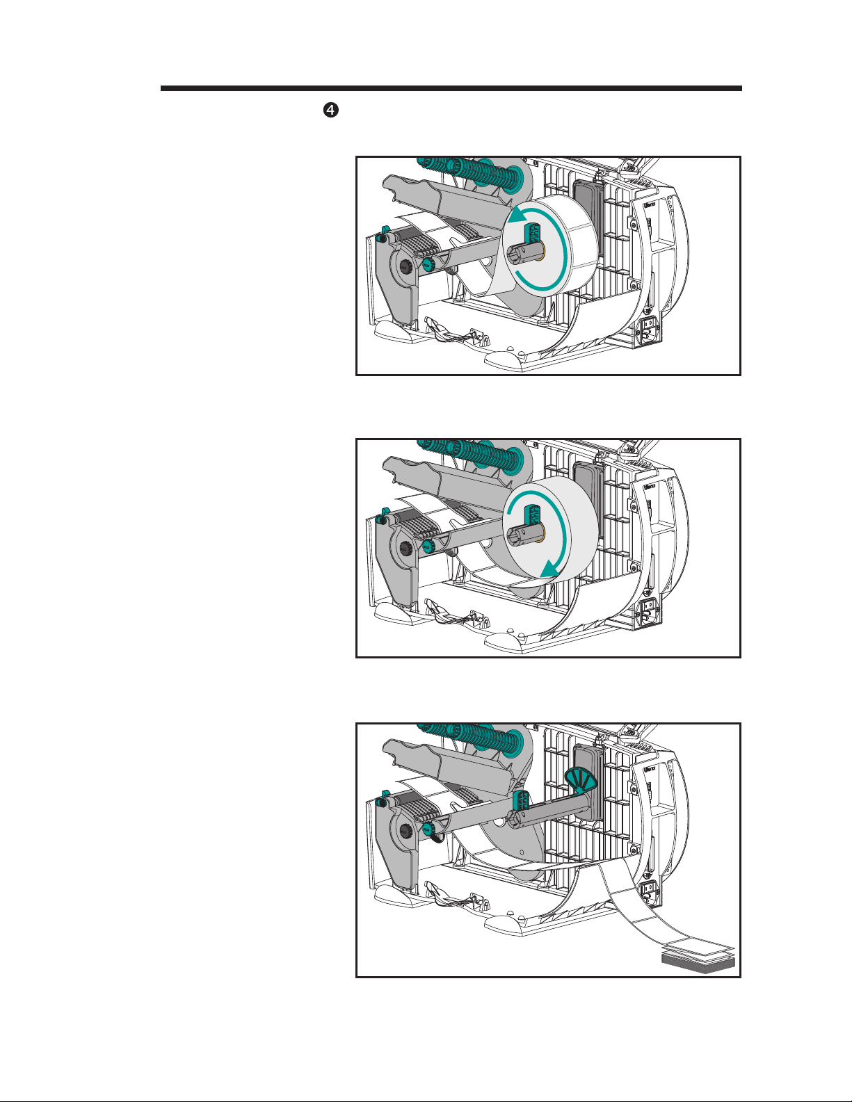
Step Remove the media clip and thread the liner un
Remove
Media Clip
Thread Liner
Around the
Liner Take-Up Tube
-
der the liner take-up tube.
Media
Clip
Step Attach the liner to the liner take-up tube with
Attach Liner to
Liner Take-Up Tube
Remove
Liner Slack
the clip. Turn the liner take-up tube counter-clockwise to remove liner slack.
46 980342-001 Rev.A
Page 53

Using the Liner Take-Up Option
MOVIE
Liner Rewind
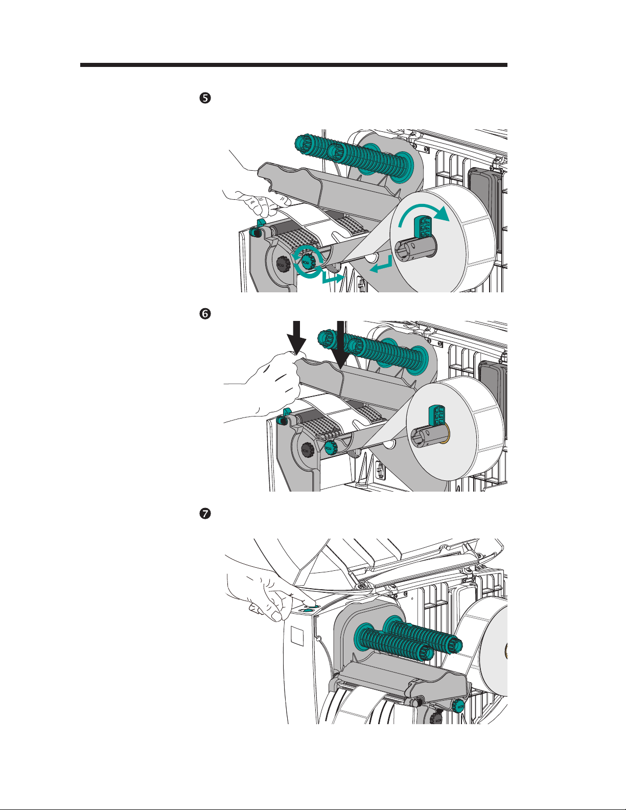
Step
Set Peel
Mode
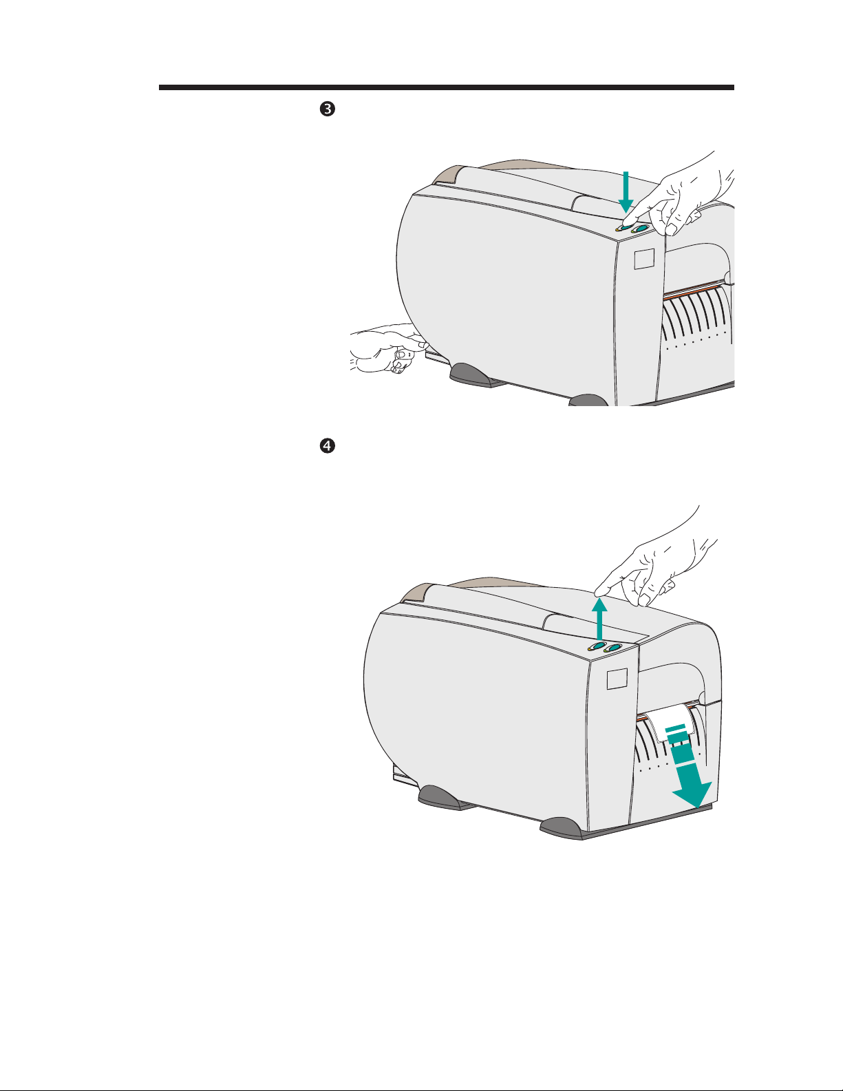
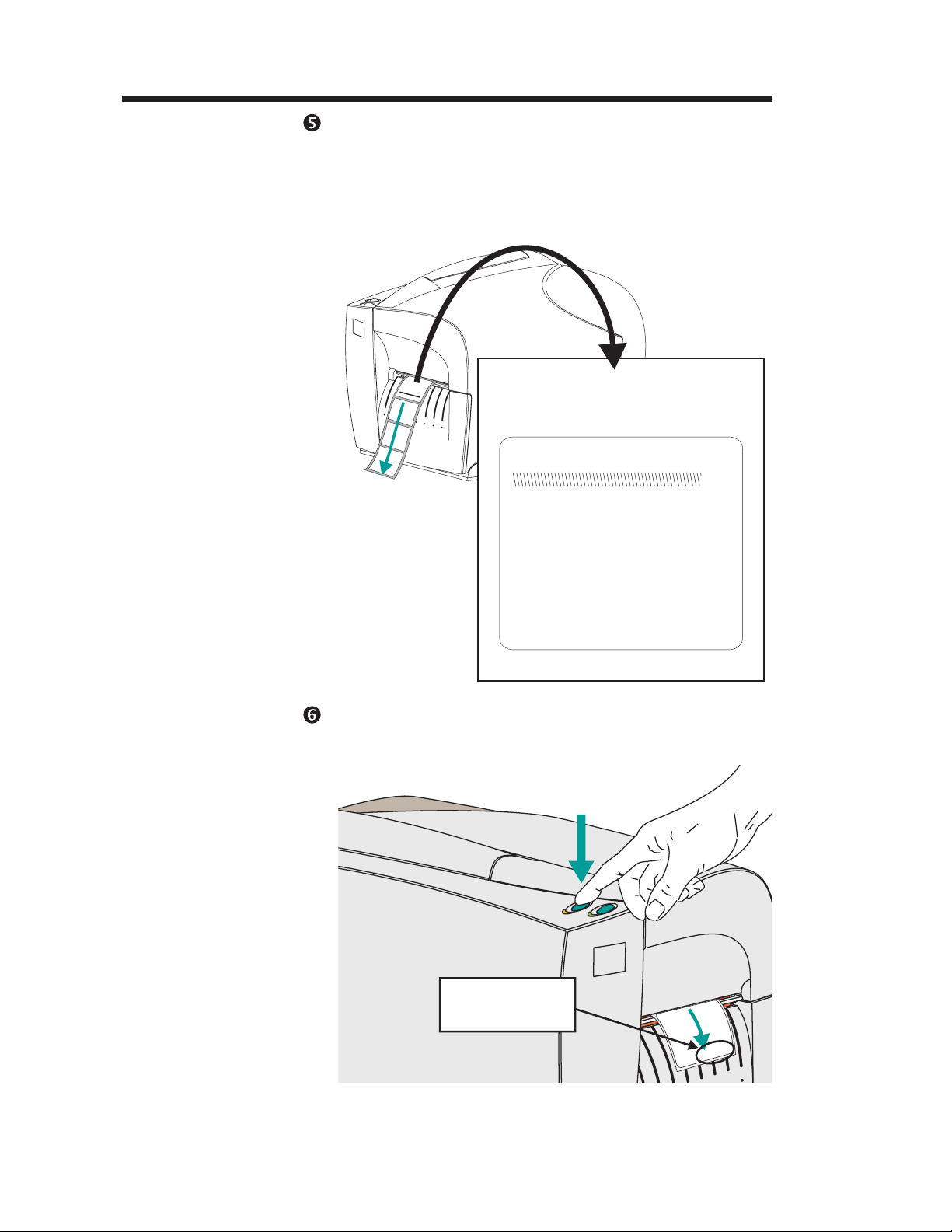
Step If necessary, press the FEED button to remove
Change the printer mode switch to “Peel”
mode. Reset the printer or cycle the power.
slack and to wind minimum of one full revolution of liner around the liner take-up tube.
Press FEED
Step Close the printer.
Close Printer
Ready for
Press and
Print Label
Dispense
980342-001 Rev.A 47
Page 54

Using the Liner Take-Up Option
Manual Label
Dispense with
Liner Take-up
Step Load and thread the labels, see page 8.
Step Press FEED and remove labels until approxi
The printer with the liner take-up mechanism
can dispense a single peeled label and wind the
backing without the Label Dispenser Assembly
in the Dispense (Peel) mode. Remove the
presented label and press the FEED button to
print the next label. This configuration must
programmed into the printer with the O,L
command.
mately 16 inches (40 mm) of liner has been ex
posed.
-
-
Step Pull the liner under the print mechanism and
liner take-up tube. Attach the liner to the liner
take-up tube with the clip. Turn the liner
take-up tube counter-clockwise to remove liner
slack. See page 46 for more details and
illustration.
Step Close the printer and press FEED to present a
blank label. Remove the label.
Step Change the printer mode switch to “Peel”
mode. Reset the printer or cycle the power.
Step Send the EPL2 O,L command to finish config
uring the printer.
48 980342-001 Rev.A
-
Page 55
Using the Media Cutter
5
Using the Media Cutter
This section provides information on the
printer’s Media Cutter option.
Media Cutter
Features
Cutter & Bezel
Assembly
Printers with the cutter option have a detachable cutter with a motorized blade. The cutter is
a self cleaning tag and label liner cutter.
Modular Accessory
Socket and Plug
980342-001 Rev.A 49
Page 56

Using the Media Cutter
Cutter Guidelines Use the media cutter to cut through continuous
paper or the label liner in the gaps between la
bels. Never cut the portion of media that has
adhesive or adhesive backing.
You can switch cutting on and off by using the
OC command. You can set form length and
gap distances by using the Q command. A sin
gle cut can be made anytime the printer is not
printing with the C (Cut Immediate) command.
Refer to the Page Mode (EPL2) programmer’s
manual for complete programming informa
tion.
Keep the cutter dry. Never use any solutions or
solvents to clean the blade. If there is a jam, follow the steps for Clearing Cutter Jams.
-
-
-
Specifications
Warranty 90 Days
Mean Time To
Failure (MTBF)
Cutting Method Rotating, double edged blade
Media
Media Type Paper, Thermal Paper, Paper Tags, Paper Label Liners
Max. Density 200 grams/meter
Min. Width 1.0 inch (25 mm)
Max. Width 4.13 inches (105 mm)
500,000 cut cycles
2
(approximately 0.010 inches (0.254 mm) thick)
50 980342-001 Rev.A
Page 57

Using the Media Cutter
MOVIE
Mounting the
Cutter
Step Turn the power off. Remove the front bezel
Step Insert the cutter plug into the accessory socket.
Bezel
Retainer
Tabs
Use this procedure to attach cutter onto the
printer.
(and peel bar if present). See Front Bezel Re
moval, page 29.
Bezel
Retainer
Slots
-
Bezel Guide
Slots
Accessory
Socket
980342-001 Rev.A 51
Bezel Guide
Tabs
Cutter Plug
Page 58

Using the Media Cutter
Step Align and insert the bezel guide tabs to the bezel
Step Load media as required. Configure the printer
guide slots and insert. Swing the cutter bezel re
taining tabs into the print mechanism’s retain
ing slots. The cutter bezel will snap and lock into
place. See “Replacing the Front Bezel”, page
30, for more details.
for the selected media with the AutoSense rou
tine or programming. Continuous media and
black line or mark media required program
ming for proper configuration.
-
-
-
-
Step Configure the printer for cutting with program
ming or software. See the programmer’s man
ual for details on setting or canceling cutter
printer command settings.
Close the cover, if open.
Cutter Removal The cutter bezel is removed like the standard
front bezel, see page 29 for the “Front Bezel Removal” procedure.
Cleaning and
Clearing the
Media Cutter
The media cutter is designed to be self cleaning
and sharpening. Occasionally, the cutter needs
to have a cleaning cycle of 5 cuts to clean and
sharpen the blade. This cleaning should be af
ter use and prior to new periods of use. This is
the only approved method for cleaning the cut
ter blade. Do not use solutions or solvents to
clean the blade.
-
-
-
-
A single cut can be made anytime the printer is
not printing with the C (Cut Immediate) com
mand. Refer to the EPL2 programmer’s man
ual for complete programming information.
52 980342-001 Rev.A
-
-
Page 59
Using the Media Cutter
Clearing Cutter
Jams
Step Remove the media cutter assembly.
Step Remove the six (6) cutter bezel retaining screws
Step Remove the two (2) screws holding the cutter
Cutter Bezel
Always turn the printer power off. The only
tool required to clear a jam is a pair of small
tweezers. Never use your fingers or sharp ob
jects to clear jams.
If you cannot remove the jammed media with
tweezers, the media cutter may be opened.
on the back of the media cutter assembly.
mechanism to the cutter mounting bracket.
Cutter Mounting
Bracket
Bezel Retaining
Screws
-
Cutter
Mounting
Screws
Cutter
Mechanism
Bezel
Retaining
Screws
Step Clean the cutter bezel and mounting bracket as
required. Do not clean the cutter mechanism
with any liquid or moistened material!
Step Reassemble the cutter assembly and then re
mount the media cutter.
-
980342-001 Rev.A 53
Page 60

Using the Media Cutter
54 980342-001 Rev.A
Page 61

Miscellaneous Printer Options
6
Miscellaneous Printer Options
This section provides information on the printer
options that do not require physical interaction
by the operator to configure or use.
Factory Installed
Printer Options
The following options are factory installed options. They can not be added in the field.
· Liner-free Label Printing
(Non Stick Platen Roller)
· Real Time Clock (RTC)
· Asian Language Printing
·
300 dot per inch print resolution
·
RS-422 Serial Port Interface
(See Appendix A)
Add-On Options The following options can easily be added to
provide added features to your printer.
·
Keyboard Display Unit (KDU) - Used for
stand alone printer operation.
·
PrintServer - Ethernet/LAN adapter
·
Narrow Roll Media Adapters
980342-001 Rev.A 55
Page 62

Miscellaneous Printer Options
Liner-free Media
Printing
Real Time Clock
Features
Liner-free printing utilizes a special platen roller
and media path design for tear and print label
ing applications. The unique liner-free media is
normally a roll of continuous media. Liner-free
printing allows the programmer to provide vari
able lengths of labels without changing the me
dia roll.
Liner-free printer’s require more frequent
cleaning of the media path, platen roller and
print head due to accumulation of small
amounts of adhesive. See Section 2 for more
details on printer maintenance procedures.
The printer’s Real Time Clock has a ten (10)
year, self contained battery power source. The
time and data are adjustable, including the displayed format. The use, access and configuration of the Real Time Clock is done through
software or programming. See the EPL2 Programmer’s manual for more details.
-
-
-
Checking for
Time & Date
Use the printer’s AutoSense procedure to generate a Dump Mode (status) printout. A printer
U command will also print a Dump Mode status
printout.
RTC Dump Mode Status Information:
·
Use it to check for the RTC option in printer.
When time and date are displayed, it shows
the presently set Time & Date and that the
RTC is installed in the printer.
·
Display presently set Time & Date.
56 980342-001 Rev.A
Page 63

Miscellaneous Printer Options
Programming with
the Real Time
Clock Option
The list below is for quick reference when pro
gramming the RTC option features:
TS - Set Time & Date
·
TT - Define Time Layout as a command or
·
Insert Time Function as a variable in a
“DATA” field.
TD - Define Date Layout as a command or
·
Insert a Date Function as a variable in a
“DATA” field.
A - ASCII or Asian (double byte ASCII text)
·
as a variable function within the “DATA”
string.
· B - Bar Code as a variable function within the
“DATA” string.
· Simple Math Functions as part of the A
(text) or B (bar code) commands.
-
Asian Language
Printers
See the EPL2 Programmer’s manual for more
details.
The Asian language capable printer supports
one of the three (3) available Asian languages:
Chinese, Korean or Japanese. The Ht-146
Asian printer, offered as a factory option only,
requires a special PCBA with additional mem
ory to support the large pictographic Asian
character sets. The standard character sets are
also supported by these printers. See the Page
mode (EPL2) Programmer’s manual for more
details.
-
980342-001 Rev.A 57
Page 64
Miscellaneous Printer Options
High Resolution
300 dpi Printers
Keyboard Display
Unit (KDU)
The high resolution 300 dots per inch printing
is available as a factory option only.
When programming, be aware that the 300 dpi
printer has 11.8 dots per millimeter verses the 8
dots per millimeter of the standard 203 dpi
printer. Multiply all 203 dpi dot measurements
(command parameters) by 1.5 to recreate ex
isting label formats. External graphics or logos
(PCX files) must be recreated or scaled to 1.5
times the original dot size to remain the same
size.
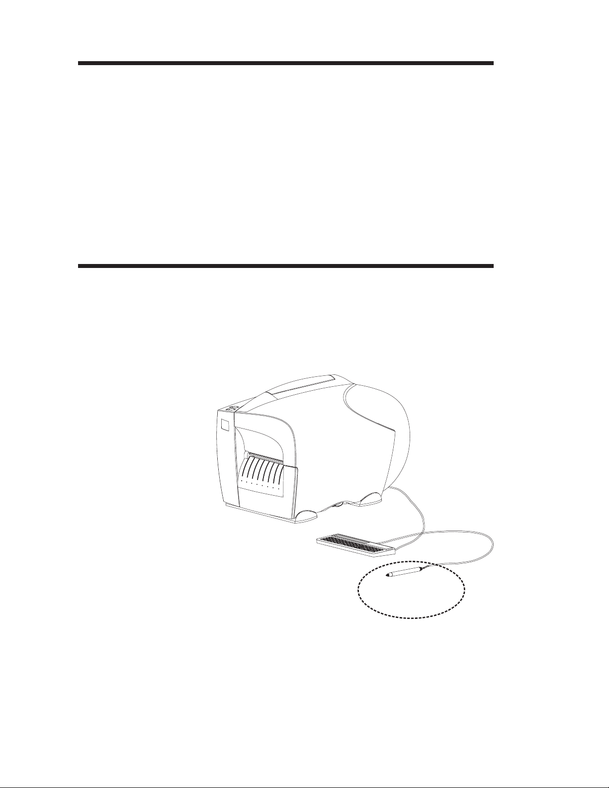
The Keyboard Display Unit allows the operator
to print label formats previously stored into the
printer’s flash memory. The operator can call
forms to print to type or scan data. The KDU
has a scanner serial port for including a third
party scanning device.
-
KDU
Setup
Printer
KDU
Scanner
(3rd Party)
See the KDU manual and the EPL2 Program
mer’s manual for details.
The KDU supports multiple languages.
-
58 980342-001 Rev.A
Page 65

Miscellaneous Printer Options
The PrintServer The PrintServer is a 10Base-T Ethernet adapter
that includes a suite of IT management and in
stallation tools. The PrintServer will work on
networks that utilize TCP/IP and/or IPX proto
cols.
The PrintServer Supports:
TCP/IP and IPX protocols
·
Windows™ 95/98
·
Windows™ NT
·
Netware
·
Peer to Peer Networking
·
· HP JetAdmin
-
-
· SNMP
See the PrintServer data sheet and the installation and operator’s guide at the Zebra web site
(http://www.zebra.com) or on the printer’s software and documentation CDROM for this
printer.
980342-001 Rev.A 59
Page 66
Miscellaneous Printer Options
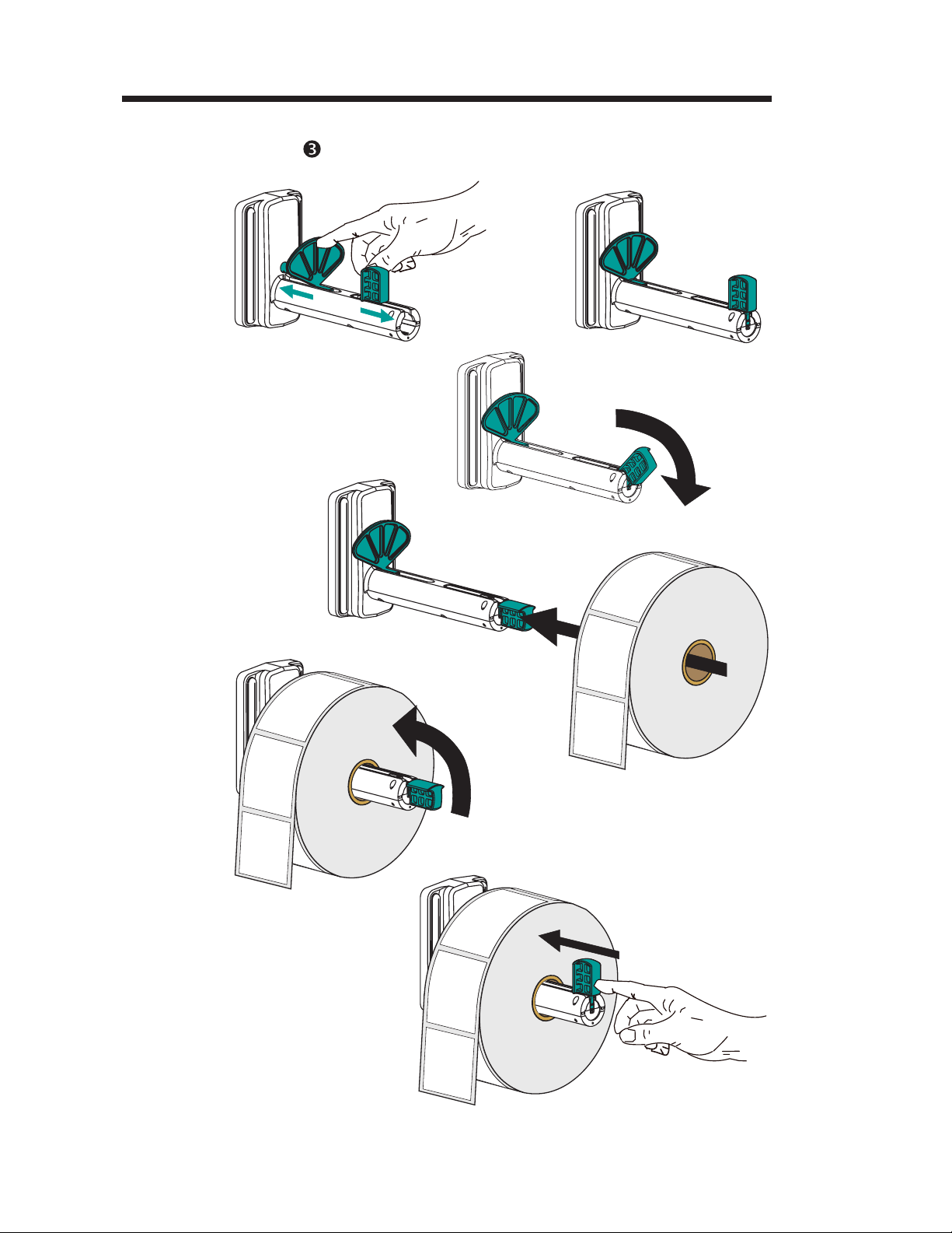
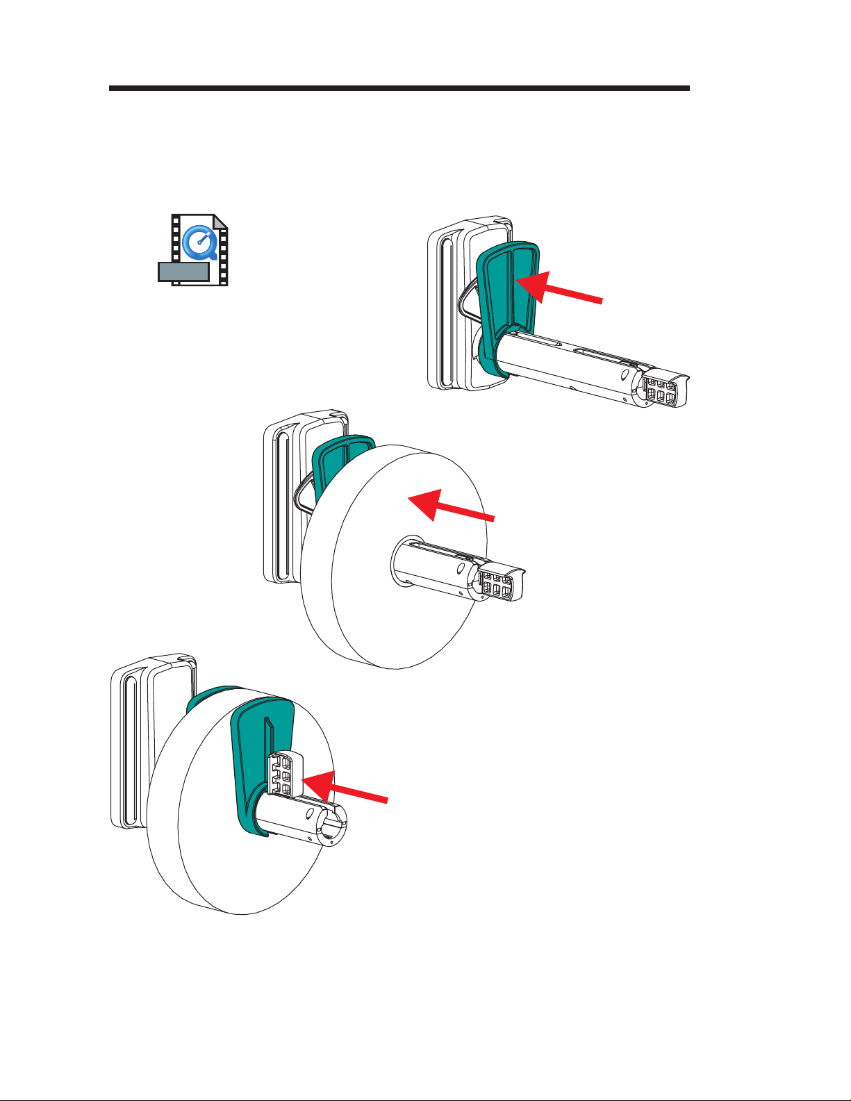
Narrow Media
Adapters
MOVIE
The printer has media roll adapters for media
that is less than 2 inches wide to a minimum
width of 1 inch. Slide the adapters on the media
roll holder and around the roll. The tall sides of
the adapters face the media roll, see below.
60 980342-001 Rev.A
Page 67

Troubleshooting
Appendix A
Troubleshooting
This section addresses the most common issues
you may face with operation, maintenance and
configuration of the printer.
Where to Start Your first troubleshooting reference source is
the Common Problems Troubleshooting table
on the following page.
980342-001 Rev.A 61
Page 68

Troubleshooting
Common Printing Problems
Troubleshooting Guide
Problem Solution or Reason
Status indicators do not
light with printer power
ON (=1).
With the POWER
indicator GREEN, the
printer appears to be
working, but nothing is
printed.
Printing stops and the
indicators are:
Power - Off
Error - Amber
1. Check power connections from the printer to
the outlet.
1. Verify that the labels are the correct type.
2. Check the roll and verify that the print surface
faces up for printing.
3. Check that the transfer ribbon is correctly
routed and has the ink side out for thermal
transfer printing, only.
1. Check for Out-of-Media or Ribbon condition,
missing labels in the middle of a roll, ribbon
damage or label jam.
2. Possible problem sensing labels.
a) For labels, verify the reflective sensor (light
source with red dot) is positioned under the
Transmissive sensor.
b) Perform AutoSense adjustment.
3. Possible problem with media.
a) Gap between the bottom of a label and the
top of the next label should be at least 1/16"
(1.6mm).
b) For tags, see Gap and Index Hole Sensing
Range, page A-70.
c) Use only Zebra approved labels and tags.
4. Possible software/programming problem.
Refer to the Page Mode (EPL2) Programming
manual for the correct data syntax.
The printer has issued
a command and the
indicators are:
Power - Off
Error - Amber
1. Media is not loaded or properly loaded.
2. When direct thermal printing, verify that the
programmed mode (or printer driver) is set for
direct thermal printing. See the programmer’s
manual for details. The printer maybe detect
ing the absence of transfer ribbon.
-
62 980342-001 Rev.A
Page 69

Problem Solution or Reason
Troubleshooting
The printer has issued
a command, media
moves and then stops.
The indicators are:
Power - Green
Error - Amber
Printing is faded or
poor quality.
Printer cuts (melts)
through the transfer
ribbon. The ribbon is
advancing normally,
i.e. at the same rate as
the media.
1. Verify that the adjustable reflective media sen
sor is correctly positioned to detect an inter la
bel gap, index holes (notches), or black marks
(stripes). See page 15 for sensor location and
setting.
2. Not detecting label gaps properly. Perform
AutoSense.
1. Clean the print head with cleaning pen.
2. Adjust print speed/darkness in software or
with programming.
3. Check the roll and verify that the media print
surface is facing up.
4. Verify that the correct combination thermal
transfer ribbon and media are in use.
5.- The print head life may have been exceeded
if quality is still poor after cleaning, see Print
Head Replacement on page 74.
1. Verify the density (heat) setting. If this is unknown reduce setting several levels the until
the transferred ink is clear and the ribbon is
not damaged.
2. Verify that the correct media is in use.
3. Verify that the ink (transfer material) side is
out on the transfer ribbon roll.
-
-
Label Dispense Mode:
Printing does not stop
between labels.
Label Dispense Mode:
Prints one label and
stops.
Cutter Option:
Cutting labels instead
of cutting between
labels.
980342-001 Rev.A 63
1. The Peel/Batch switch in the rear of the
printer is not set to peel.
2. The dispenser door is open (down position).
1. Programming - Verify the quantity has been
correctly set.
1. Programming - Verify form length setting.
2. Check that peel switch is in the "batch" posi
tion (towards outside of printer).
-
Page 70

Troubleshooting
Printer
Configuration
Settings
The printer has flash (non-volatile) memory to
store printer configuration settings. The settings
are stored in flash memory and are set by
programing, printer drivers or the AutoSense
routine. The settings are shown on the Dump
mode printout or can be reported back to the
host via the serial port.
The following are the basic settings stored in the
printer:
Print Mode - Direct (OD) or Thermal Transfer
(O)
Speed (S)
Density (D) or heat applied
Form (label) length and gap in dots (Q)
Form (label) width in dots (q)
Serial Port (Y)
Margin (R)
Buffer Mode (r)
Dump Mode
Printout
(See the U command in
the Programmer’s manual
for details)
Options: D
Print Mode is Direct Thermal (OD)
64 980342-001 Rev.A
Page 71

Troubleshooting
Media The two types of printing methods supported
by the Ht-146 printer family are direct thermal
and thermal transfer. Direct thermal media is
chemically treated to produce print without a
ribbon. Thermal transfer printing uses heat to
transfer wax, resin or a combination of both
from the transfer ribbon to the media.
The printer is set by default to direct thermal
printing. Set the printer to thermal transfer
mode to activate a ribbon out sensor.
Media Sensing The printer is equipped with a transmissive
(gap) sensor, reflective (black mark) sensor,
and a reflective ribbon out sensor. The
transmissive and ribbon out sensors are fixed
position sensors. The reflective sensor is adjustable. Printers with the label dispense option,
have a reflective (label taken) sensor.
The transmissive (gap) sensor is set by
AutoSense and it adjusts the sensitivity and detection levels for the media in use. The
transmissive sensor also detects the media out
condition. The sensor’s light source comes
from the adjustable reflective sensor when set
immediately below the gap sensor (under the
media).
The reflective (black mark) sensor senses light
(media) and dark (black marks) on the media
backing (or liner). The reflective sensor is ad
justable from a near center position to the out
side edge of the media (towards the inside
wall).
The ribbon out sensor reflects light off the rib
bon’s reflective end marker (trailer). When rib
bon is present (and unused), the light is stopped.
-
-
-
-
The label taken sensor detects light reflected
from a peeled label waiting to be removed.
980342-001 Rev.A 65
Page 72

Troubleshooting
Reflective Sensor
Positioning
Top Of Form
Sensing
Gap Sensing The gap sensing feature depends on the ability
The printer has a moveable sensor to detect
black lines (or marks) or index holes (or
notches) from the back side of the media. The
sensor includes a red targeting light for ease of
use. The sensor should be centered on the
black mark or index hole (or notch). Move the
sensor position by turning the black adjustment
knob on the lower print mechanism. Typically,
the media does not require a sensor position
adjustment.
To accommodate different media and media
dimensions, your printer is equipped with sen
sors capable of detecting the top of form for la
bels or tags. Two methods are used by the
printer for top of form sensing: gap sensing and
black mark sensing.
of the transmissive (gap) sensor to “see
through” the label liner between labels. Label
and label backing opacity vary due to manufacturing differences in label stock. The sensor
may have difficulty distinguishing the difference between labels and the liner. This may require the user to AutoSense the media. Set the
gap sensor’s sensitivity with the AutoSense fea
ture. Verify that the reflective sensor’s position
(note the red light) is immediately below the
transmissive (gap) sensor. For all gap sensing
operations, the sensor must be in this position.
-
-
-
Black Mark
Sensing
66 980342-001 Rev.A
The black mark uses a reflective (black mark)
sensor to detect a black line (mark) on the
media backing. The black mark sensor is used
with special labels that have a black mark
printed on the back of the label liner or tag
between each label or tag. When printing with
black mark media, the sensor does not need to
be aligned with the upper transmissive (gap)
sensor to work and can be moved.
Page 73

Troubleshooting
Black Mark and
Index Hole
Sensing Range
Sensor
Adjustment
Range
Inside Edge
of Tag Stock
The reflective sensor’s position is indicated by a
red light that is visible through the media with
the print head open. The sensor can be moved
by rotating the black knob on the lower portion
of the print mechanism. For proper sensing, en
sure that the sensor is aligned with the center
portion of the black mark or index hole/notch.
The following dimensions show the required
position of the index hole or notch on tag stock
.
C
min. max.
B
A
Tag Tear-away
-
.314 Nominal Sensor Location
Dimension Min. Max. Nominal
A .236" None .512"
B .079" .512" .118"
C .098" 1.520" N/A
Print Head Life The print head has a limited life and is consid
ered a consumable item. The media rubs
across the print head print elements and wears
away the surface. This process is affected by
many factors relating to the media material, op
erational settings and environment.
-
-
980342-001 Rev.A 67
Page 74
Troubleshooting
Serial Interface
Communication
Configuration
RS-232 Serial
Interface Cable
Wiring
The printer’s serial port is configured with the
Y command for the printer. The printer sup
ports interface data rates from 1200 to 38,400
baud. See the EPL2 programmer's manual for
details.
The printer’s serial port default configuration is:
9600 baud
8 bit data
1 stop bit
No parity
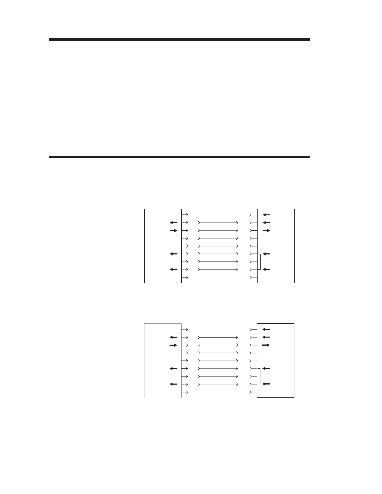
The figure below displays the cable wiring re
quired to use the printer’s serial interface.
DB-9
Pin #
N/C
RxD
TxD
DTR
GND
DSR
RTS
CTS
RI
Female DB-9 to Male DB-9
Cable P/N 300017-006 (6') or 300017-010 (10')
DB-9
Pin #
11
22
33
44
55
66
77
88
99
PrinterHost
+5 Volts*
TxD
RxD
N/C
GND
RDY
N/C
RDY
N/C
-
-
DB-25
Pin #
N/C
RxD
TxD
DTR
GND
DSR
RTS
CTS
RI
Female DB-25 to Male DB-9
Cable P/N 300018-006 (6')
*+5 volts at 150 mA for external device (e.g. KDU or scanner)
DB-9
Pin #
18
23
32
420
57
66
74
85
922
PrinterHost
+5 Volts*
TxD
RxD
N/C
GND
RDY
N/C
RDY
N/C
68 980342-001 Rev.A
Page 75

Troubleshooting
Parallel Interface
Cable Wiring
The figure below displays the cable wiring
required to use the printer's Centronics parallel
interface.
HOST
STROBE
DATA 0
DATA 1
DATA 2
DATA 3
DATA 4
DATA 5
DATA 6
DATA 7
ACK/
BUSY
PAPER ERR.
READY
INIT
ERROR/
N/A
N/A
N/A
SIG. GND
SIG. GND
SIG. GND
SIG. GND
SIG. GND
SIG. GND
SIG. GND
DB-25
Pin No.
1
2
3
4
5
6
7
8
9
10
11
12
13
14
15
16
17
18
19
20
21
22
23
24
25
Centronics
Pin No.
1
2
3
4
5
6
7
8
9
10
11
12
13
14
15
16
17
18
19
20
21
22
23
24
25
PRINTER
STROBE
DATA 0
DATA 1
DATA 2
DATA 3
DATA 4
DATA 5
DATA 6
DATA 7
ACK/
BUSY
PAPER ERR.
READY
INIT
ERROR/
N/A
N/A
+5V
SIG. GND
SIG. GND
SIG. GND
SIG. GND
SIG. GND
SIG. GND
Female DB-25 to Male Centronics
980342-001 Rev.A
(Cable)
+5 volts at 300 mA for external device (e.g. PrintServer)
69
Page 76

Troubleshooting
USB Interface
Cable Wiring
USB
Connector
The figure below displays the cable wiring
required to use the printer's USB interface.
Pin Signal
2
3
1
4
1 Vbus - N/C
2D-
3D+
4 Ground
Shell
Shield /
Drain Wire
For printer supported operating systems and
USB drivers, see the software and documenta
tion CD or visit the Zebra printer web site at:
http://www.zebra.com
For information on the USB interface go to the
USB web site, at:
http://www.usb.org
-
Printer Option:
RS-422 Serial
Interface Cable
Wiring
The figure below displays the cable wiring required to use the printer’s optional RS-422 serial interface.
DB-9
Printer
Pin #
1
2
3
4
5
6
7
8
9
+5V *
+T
+R
–R
N/C
–T
N/C
–T
N/C
*+5 volts at 150 mA for external device
70 980342-001 Rev.A
Page 77
Print Head Replacement Procedures
Appendix B
Print Head Replacement Procedures
The following section has print head evaluation
information and print head replacement procedure.
Warning - Static Discharge - The discharge
of electrostatic energy that accumulates on the
surface of the human body or other surfaces can
damage or destroy the print head or electronic
components used in this device.
DO NOT TOUCH the print head or the
electronic components under the print head
assembly accept during replacement.
Prepare a static-safe work area for repair. The
area must include a properly grounded
conductive cushioned mat to hold the printer
and a conductive wrist strap for the technician.
ESD protective devices are available from most
electronic supply stores or by contacting 3M
corporation at (800) 328-1368.
980342-001 Rev.A 71
Page 78
Print Head Replacement Procedures
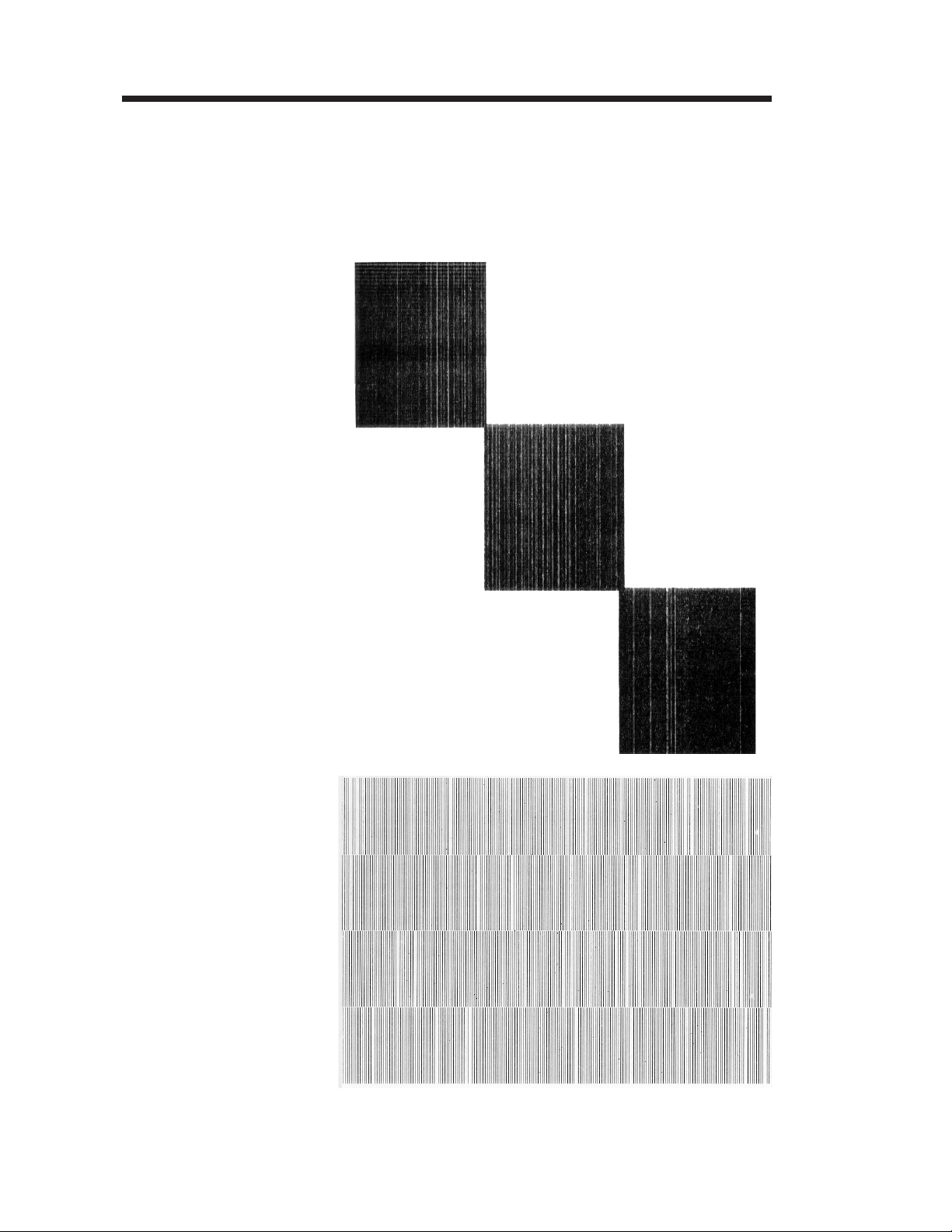
Identifying Print
Head Problems
Weak or Damaged
Print Elements
(Full-On Print
Pattern)
The print head wears with printer use. If the
print quality does not improve after cleaning,
the print head may require replacement. Print
ing with worn damaged print elements may
create unreadable bar codes. The following are
examples of print head wear or damage.
-
Weak or Damaged
Print Elements or
Print Logic
(Rotating Print
Element Pattern)
72 980342-001 Rev.A
Page 79

Print Head Replacement Procedures
Print head damage can be caused by: improper
cleaning with unapproved fluids or imple
ments, electro static discharge (ESD), and
touching the print head (contaminates, ESD
and body oil acids).
-
980342-001 Rev.A 73
Page 80

Print Head Replacement Procedures
Print Head
Replacement
MOVIE
Step 1
Turn printer power off. Open the print head.
Remove any thermal transfer ribbon, if present.
Step 2 Remove the print head shroud. Slide the
shroud forward to detach (unsnap) it from the
print head mechanism.
Slide Shroud
Forward
Push
Here
Wiggle the
Shroud
Set Shroud
Aside
74 980342-001 Rev.A
Page 81

Print Head Replacement Procedures
Step 3 Push the print head up into the print mecha
Push The Print Head
Bracket to the Back
(Cables Not Shown)
Spring Action Pops
Bracket Out
-
nism and slide it to the back of the printer.
Step 4 Disconnect the print head cables. Avoid pulling
the cables.
980342-001 Rev.A 75
Page 82

Print Head Replacement Procedures
Step 5 Disconnect the ground wire lug on the top of
the print head bracket with a Philips screw
driver. Discard old print head and bracket.
Disconnect
Ground Wire
-
Step 6 Reconnect the new print head and bracket as-
sembly to the ground wire.
Step 7 Reconnect the print head cable to the print
head. The connectors are keyed to go together
one way. Do not force the connectors. The connector with the black wires goes on the outside
and the connector with the white wires goes on
the inside toward the center panel of the
printer.
76 980342-001 Rev.A
Page 83

Print Head Replacement Procedures
Step 8 Align the center of the print head bracket with
the center (V) of the print head spring. Push the
bracket's center slot onto the shroud's center
post (and screw).
Spring
Center
Print Head
on Spring
Tabs
Retainers
(colored for reference)
Place Bracket
onto
Center Post
Centering
Guide
Center
Post
980342-001 Rev.A 77
Page 84

Print Head Replacement Procedures
Step 9 While pressing up on the print head, slide the
bracket's tabs over the upper print mechanism's
print head retainer lip. Even upward pressure
on both sides of the print head is required to
clear the front edge of the retainer lip. Slide the
bracket to the front of printer.
Press Print Head
Tabs over the
top of the
Bracket
Retainers
Step 10 Dress the print head cable away from the print
head bracket and replace the print head
shroud. Align the shroud to the three (3) posts
(and screws) and slide to the back. The shroud
will snap in place.
Step 11 Clean the print head. See page 26 for more
details.
78 980342-001 Rev.A
Page 85

Cover Removal
Appendix C
Cover Removal
The following section describes the cover removal for service.
Cover Removal
Procedure
This procedure is intended for the field service
engineer or technician.
The printer's cover is not designed to be removed repeatedly.
Prepare a static-safe work area before opening
the printer for repair. The area must include a
properly grounded conductive cushioned mat
to hold the printer and a conductive wrist strap
for the technician. ESD protective devices are
available from most electronic supply stores or
by contacting 3M corporation at (800)
328-1368.
Shock Hazard
Always turn off the printer before performing
any maintenance or repair operations. Wait for
the indicator light to be dark, then unplug the
power cord.
980342-001 Rev.A 79
Page 86

Cover Removal
MOVIE
Step 1 Remove the top cover (door). Remove the two
screws on the cover's front hinge bracket.
Swing the top cover off the back hinge bracket
and set it aside.
80 980342-001 Rev.A
Page 87

Cover Removal
Step 2 Remove the six screws retaining the left side
cover to the printer's center panel.
Step 3 Serial Port - Remove the two 3/16" hex screws.
Remove
Remove
980342-001 Rev.A 81
Page 88

Cover Removal
Step 4 Pry the cover off with your hands. Do not use
tools. Start at the front corner working around
to the top and then to the rear of the printer.
Step 5 Slip the left cover and I/O plate off the main
Replacing the
Cover
PCBA in the rear of the printer.
Set the cover down next to the left side of the
printer. Note that the cover is attached to the
main PCBA by the control panel's cable.
Reverse the cover removal process. Do not
over tighten the screws. Do not cross-thread the
pre-existing threads made during the original
assembly of the printer. Use a torque setting of
4.7 ±1 inch pounds (0,531 ± 0,113 Nm).
82 980342-001 Rev.A
 Loading...