

Page 1

Omnii HDK
User Manual
(Omnii XT10)
December 8, 2010 P/N 8100210.A
ISO 9001 Certified
Quality Management System
Page 2

© Copyright 2010 by Psion Teklogix Inc.
2100 Meadowvale Boulevard, Mississauga, Ontario, Canada L5N 7J9
http://www.psionteklogix.com
This document and the information it contains is the property of Psion Teklogix Inc., is issued in strict confidence, and is not to be reproduced or copied, in whole or in part, except for the sole purpose of promoting the
sale of Psion Teklogix manufactured goods and services. Furthermore, this document is not to be used as a
basis for design, manufacture, or sub-contract, or in any manner detrimental to the interests of
Psion Teklogix Inc.
Disclaimer
Every effort has been made to make this material complete, accurate, and up-to-date. In addition, changes
are periodically added to the information herein; these changes will be incorporated into new editions of
the publication.
Psion Teklogix Inc. reserves the right to make improvements and/or changes in the product(s) and/or the program(s) described in this document without notice, and shall not be responsible for any damages, including
but not limited to consequential damages, caused by reliance on the material presented, including but not
limited to typographical errors.
Omnii™ is a trademark of Psion Teklogix Inc.
Windows
®
and the Windows Logo are trademarks or registered trademarks of Microsoft Corporation in the
United States and/or other countries.
The Bluetooth
®
word mark and logos are owned by Bluetooth SIG, Inc. and any use of such marks by Psion
Teklogix Inc. is under license.
All trademarks and trade names are the property of their respective holders.
Page 3

Return-To-Factory Warranty
Psion Teklogix Inc. provides a return to factory warranty on this product for a period of twelve (12) months in
accordance with the Statement of Limited Warranty and Limitation of Liability provided at:
www.psionteklogix.com/warranty
The warranty on Psion Teklogix manufactured equipment does not extend to any product that has been tampered with, altered, or repaired by any person other than an employee of an authorized Psion Teklogix service
organization. See Psion Teklogix terms and conditions of sale for full details.
Important: Psion Teklogix warranties take effect on the date of shipment.
Service and Information
Psion Teklogix provides a complete range of product support services and information to its customers worldwide. Services include technical support and product repairs. To locate your local support services, please go
to
www.psionteklogix.com/service-and-support.htm
To access further information on current and discontinued products, please go to http://community.psiontek-
logix.com/login.aspx?ReturnUrl=%2fdefault.aspx and log in. A section of archived product information is available
online.
Page 4

Page 5

TABLE OF CONTENTS
Chapter 1: Introduction
1.1 About This Manual . . . . . . . . . . . . . . . . . . . . . . . . . . . . . . . . . . . . . . . . . . . . . . . . . . . . . . . . . . . . . . . . . . . . . . . . . . . . . . . . . . . . . . . . . 3
1.2 Text Conventions . . . . . . . . . . . . . . . . . . . . . . . . . . . . . . . . . . . . . . . . . . . . . . . . . . . . . . . . . . . . . . . . . . . . . . . . . . . . . . . . . . . . . . . . . . .4
1.3 About the HDK . . . . . . . . . . . . . . . . . . . . . . . . . . . . . . . . . . . . . . . . . . . . . . . . . . . . . . . . . . . . . . . . . . . . . . . . . . . . . . . . . . . . . . . . . . . . . 4
1.4 Development Platform . . . . . . . . . . . . . . . . . . . . . . . . . . . . . . . . . . . . . . . . . . . . . . . . . . . . . . . . . . . . . . . . . . . . . . . . . . . . . . . . . . . . . . 4
1.5 Contents of the HDK . . . . . . . . . . . . . . . . . . . . . . . . . . . . . . . . . . . . . . . . . . . . . . . . . . . . . . . . . . . . . . . . . . . . . . . . . . . . . . . . . . . . . . . 4
1.5.1 Files in the HDK . . . . . . . . . . . . . . . . . . . . . . . . . . . . . . . . . . . . . . . . . . . . . . . . . . . . . . . . . . . . . . . . . . . . . . . . . . . . . . . . . . . 5
1.6 Obtaining the HDK . . . . . . . . . . . . . . . . . . . . . . . . . . . . . . . . . . . . . . . . . . . . . . . . . . . . . . . . . . . . . . . . . . . . . . . . . . . . . . . . . . . . . . . . . 7
1.7 About the Omnii Hand-Held Computer . . . . . . . . . . . . . . . . . . . . . . . . . . . . . . . . . . . . . . . . . . . . . . . . . . . . . . . . . . . . . . . . . . . . . 7
Chapter 2: Getting Started
2.1 Overview . . . . . . . . . . . . . . . . . . . . . . . . . . . . . . . . . . . . . . . . . . . . . . . . . . . . . . . . . . . . . . . . . . . . . . . . . . . . . . . . . . . . . . . . . . . . . . . . . 11
2.2 What Can I Do With the Omnii HDK? . . . . . . . . . . . . . . . . . . . . . . . . . . . . . . . . . . . . . . . . . . . . . . . . . . . . . . . . . . . . . . . . . . . . 11
2.3 Expansion Areas . . . . . . . . . . . . . . . . . . . . . . . . . . . . . . . . . . . . . . . . . . . . . . . . . . . . . . . . . . . . . . . . . . . . . . . . . . . . . . . . . . . . . . . . . . 12
2.4 Expansion Device Requirements . . . . . . . . . . . . . . . . . . . . . . . . . . . . . . . . . . . . . . . . . . . . . . . . . . . . . . . . . . . . . . . . . . . . . . . . . . 13
2.4.1 Device EEPROM . . . . . . . . . . . . . . . . . . . . . . . . . . . . . . . . . . . . . . . . . . . . . . . . . . . . . . . . . . . . . . . . . . . . . . . . . . . . . . . . 13
2.4.2 Device Registry Keys . . . . . . . . . . . . . . . . . . . . . . . . . . . . . . . . . . . . . . . . . . . . . . . . . . . . . . . . . . . . . . . . . . . . . . . . . . . . 13
Chapter 3: Hardware
3.1 Overview . . . . . . . . . . . . . . . . . . . . . . . . . . . . . . . . . . . . . . . . . . . . . . . . . . . . . . . . . . . . . . . . . . . . . . . . . . . . . . . . . . . . . . . . . . . . . . . . . 17
3.2 Hardware Variants . . . . . . . . . . . . . . . . . . . . . . . . . . . . . . . . . . . . . . . . . . . . . . . . . . . . . . . . . . . . . . . . . . . . . . . . . . . . . . . . . . . . . . . . 17
3.2.1 Display Variants. . . . . . . . . . . . . . . . . . . . . . . . . . . . . . . . . . . . . . . . . . . . . . . . . . . . . . . . . . . . . . . . . . . . . . . . . . . . . . . . . . 17
3.2.2 Keyboard Variants . . . . . . . . . . . . . . . . . . . . . . . . . . . . . . . . . . . . . . . . . . . . . . . . . . . . . . . . . . . . . . . . . . . . . . . . . . . . . . . 17
3.2.3 Back Cover Variants . . . . . . . . . . . . . . . . . . . . . . . . . . . . . . . . . . . . . . . . . . . . . . . . . . . . . . . . . . . . . . . . . . . . . . . . . . . . . 18
3.2.4 Scanner/Imager Variants . . . . . . . . . . . . . . . . . . . . . . . . . . . . . . . . . . . . . . . . . . . . . . . . . . . . . . . . . . . . . . . . . . . . . . . . . 18
3.3 Processor . . . . . . . . . . . . . . . . . . . . . . . . . . . . . . . . . . . . . . . . . . . . . . . . . . . . . . . . . . . . . . . . . . . . . . . . . . . . . . . . . . . . . . . . . . . . . . . . . 19
3.4 Identifying Hardware . . . . . . . . . . . . . . . . . . . . . . . . . . . . . . . . . . . . . . . . . . . . . . . . . . . . . . . . . . . . . . . . . . . . . . . . . . . . . . . . . . . . . 20
3.5 The LEDs . . . . . . . . . . . . . . . . . . . . . . . . . . . . . . . . . . . . . . . . . . . . . . . . . . . . . . . . . . . . . . . . . . . . . . . . . . . . . . . . . . . . . . . . . . . . . . . . 20
3.6 Connectors . . . . . . . . . . . . . . . . . . . . . . . . . . . . . . . . . . . . . . . . . . . . . . . . . . . . . . . . . . . . . . . . . . . . . . . . . . . . . . . . . . . . . . . . . . . . . . . 20
3.6.1 Connector Locations . . . . . . . . . . . . . . . . . . . . . . . . . . . . . . . . . . . . . . . . . . . . . . . . . . . . . . . . . . . . . . . . . . . . . . . . . . . . . 20
3.7 Power Management. . . . . . . . . . . . . . . . . . . . . . . . . . . . . . . . . . . . . . . . . . . . . . . . . . . . . . . . . . . . . . . . . . . . . . . . . . . . . . . . . . . . . . . 21
3.7.1 Batteries. . . . . . . . . . . . . . . . . . . . . . . . . . . . . . . . . . . . . . . . . . . . . . . . . . . . . . . . . . . . . . . . . . . . . . . . . . . . . . . . . . . . . . . . . . 21
Chapter 4: Software
4.1 Overview . . . . . . . . . . . . . . . . . . . . . . . . . . . . . . . . . . . . . . . . . . . . . . . . . . . . . . . . . . . . . . . . . . . . . . . . . . . . . . . . . . . . . . . . . . . . . . . . . 25
4.2 Drivers . . . . . . . . . . . . . . . . . . . . . . . . . . . . . . . . . . . . . . . . . . . . . . . . . . . . . . . . . . . . . . . . . . . . . . . . . . . . . . . . . . . . . . . . . . . . . . . . . . . 25
4.2.1 Windows Drivers. . . . . . . . . . . . . . . . . . . . . . . . . . . . . . . . . . . . . . . . . . . . . . . . . . . . . . . . . . . . . . . . . . . . . . . . . . . . . . . . . 25
4.2.2 Non-Psion Teklogix Drivers . . . . . . . . . . . . . . . . . . . . . . . . . . . . . . . . . . . . . . . . . . . . . . . . . . . . . . . . . . . . . . . . . . . . . . 25
4.3 System Initialization . . . . . . . . . . . . . . . . . . . . . . . . . . . . . . . . . . . . . . . . . . . . . . . . . . . . . . . . . . . . . . . . . . . . . . . . . . . . . . . . . . . . . . 25
4.4 Registry Keys. . . . . . . . . . . . . . . . . . . . . . . . . . . . . . . . . . . . . . . . . . . . . . . . . . . . . . . . . . . . . . . . . . . . . . . . . . . . . . . . . . . . . . . . . . . . . 26
4.4.1 Registry Settings for Expansion Devices. . . . . . . . . . . . . . . . . . . . . . . . . . . . . . . . . . . . . . . . . . . . . . . . . . . . . . . . . . 26
4.4.1.1 Device Information Registry Keys . . . . . . . . . . . . . . . . . . . . . . . . . . . . . . . . . . . . . . . . . . . . . . . . . . . . . 28
4.4.1.2 Device Driver Registry Keys . . . . . . . . . . . . . . . . . . . . . . . . . . . . . . . . . . . . . . . . . . . . . . . . . . . . . . . . . . . 30
4.4.2 Software Registry Entries . . . . . . . . . . . . . . . . . . . . . . . . . . . . . . . . . . . . . . . . . . . . . . . . . . . . . . . . . . . . . . . . . . . . . . . . 32
Psion Teklogix Omnii HDK User Manual i
Page 6

Contents
4.5 Device Detection and Driver Loading Sequence. . . . . . . . . . . . . . . . . . . . . . . . . . . . . . . . . . . . . . . . . . . . . . . . . . . . . . . . . . . 32
4.6 Serial (COM) Port Assignments. . . . . . . . . . . . . . . . . . . . . . . . . . . . . . . . . . . . . . . . . . . . . . . . . . . . . . . . . . . . . . . . . . . . . . . . . . . 33
4.7 Omnii HDK Application Development Software . . . . . . . . . . . . . . . . . . . . . . . . . . . . . . . . . . . . . . . . . . . . . . . . . . . . . . . . . . 34
4.7.1 Windows Embedded CE 6.0 Development Platform for Visual Studio . . . . . . . . . . . . . . . . . . . . . . . . . . . . 34
4.7.2 Psion Teklogix Mobile Devices SDK . . . . . . . . . . . . . . . . . . . . . . . . . . . . . . . . . . . . . . . . . . . . . . . . . . . . . . . . . . . . . 34
4.7.3 Omnii HDK Development Files . . . . . . . . . . . . . . . . . . . . . . . . . . . . . . . . . . . . . . . . . . . . . . . . . . . . . . . . . . . . . . . . . . 34
4.7.4 Omnii HDK API Functions . . . . . . . . . . . . . . . . . . . . . . . . . . . . . . . . . . . . . . . . . . . . . . . . . . . . . . . . . . . . . . . . . . . . . . . 36
4.7.4.1 Hdk7545_ExpansionSlotFromActiveRegKey . . . . . . . . . . . . . . . . . . . . . . . . . . . . . . . . . . . . . . . . . . 36
4.7.4.2 Hdk7545_Open . . . . . . . . . . . . . . . . . . . . . . . . . . . . . . . . . . . . . . . . . . . . . . . . . . . . . . . . . . . . . . . . . . . . . . . . 36
4.7.4.3 Hdk7545_Close . . . . . . . . . . . . . . . . . . . . . . . . . . . . . . . . . . . . . . . . . . . . . . . . . . . . . . . . . . . . . . . . . . . . . . . . 37
4.7.4.4 Hdk7545_SetPower . . . . . . . . . . . . . . . . . . . . . . . . . . . . . . . . . . . . . . . . . . . . . . . . . . . . . . . . . . . . . . . . . . . . 38
4.7.4.5 Hdk7545_GetPower. . . . . . . . . . . . . . . . . . . . . . . . . . . . . . . . . . . . . . . . . . . . . . . . . . . . . . . . . . . . . . . . . . . . 38
4.7.4.6 Hdk7545_SetPowerMode . . . . . . . . . . . . . . . . . . . . . . . . . . . . . . . . . . . . . . . . . . . . . . . . . . . . . . . . . . . . . . 39
4.7.4.7 Hdk7545_GetPowerMode. . . . . . . . . . . . . . . . . . . . . . . . . . . . . . . . . . . . . . . . . . . . . . . . . . . . . . . . . . . . . . 40
4.7.4.8 Hdk7545_ExpansionSetPinDirection . . . . . . . . . . . . . . . . . . . . . . . . . . . . . . . . . . . . . . . . . . . . . . . . . . . 41
4.7.4.9 Hdk7545_ExpansionGetPinDirection . . . . . . . . . . . . . . . . . . . . . . . . . . . . . . . . . . . . . . . . . . . . . . . . . . 42
4.7.4.10 Hdk7545_ExpansionSetPinMode. . . . . . . . . . . . . . . . . . . . . . . . . . . . . . . . . . . . . . . . . . . . . . . . . . . . . . . 43
4.7.4.11 Hdk7545_ExpansionGetPinMode . . . . . . . . . . . . . . . . . . . . . . . . . . . . . . . . . . . . . . . . . . . . . . . . . . . . . . 44
4.7.4.12 Hdk7545_ExpansionSetPinFunction . . . . . . . . . . . . . . . . . . . . . . . . . . . . . . . . . . . . . . . . . . . . . . . . . . . 46
4.7.4.13 Hdk7545_ExpansionGetPinFunction . . . . . . . . . . . . . . . . . . . . . . . . . . . . . . . . . . . . . . . . . . . . . . . . . . . 47
4.7.4.14 Hdk7545_ExpansionSetPinState . . . . . . . . . . . . . . . . . . . . . . . . . . . . . . . . . . . . . . . . . . . . . . . . . . . . . . . 48
4.7.4.15 Hdk7545_ExpansionGetPinState . . . . . . . . . . . . . . . . . . . . . . . . . . . . . . . . . . . . . . . . . . . . . . . . . . . . . . . 49
4.7.4.16 Hdk7545_ExpansionSetPullUpDown . . . . . . . . . . . . . . . . . . . . . . . . . . . . . . . . . . . . . . . . . . . . . . . . . . 50
4.7.4.17 Hdk7545_ExpansionGetIrq . . . . . . . . . . . . . . . . . . . . . . . . . . . . . . . . . . . . . . . . . . . . . . . . . . . . . . . . . . . . 51
4.7.4.18 Hdk7545_ReadEepromHeader . . . . . . . . . . . . . . . . . . . . . . . . . . . . . . . . . . . . . . . . . . . . . . . . . . . . . . . . . 52
4.7.4.19 Hdk7545_WriteEepromHeader. . . . . . . . . . . . . . . . . . . . . . . . . . . . . . . . . . . . . . . . . . . . . . . . . . . . . . . . . 53
4.7.4.20 Hdk7545_ReadEepromExtendedData . . . . . . . . . . . . . . . . . . . . . . . . . . . . . . . . . . . . . . . . . . . . . . . . . . 55
4.7.4.21 Hdk7545_WriteEepromExtendedData. . . . . . . . . . . . . . . . . . . . . . . . . . . . . . . . . . . . . . . . . . . . . . . . . . 56
4.7.5 API Structures . . . . . . . . . . . . . . . . . . . . . . . . . . . . . . . . . . . . . . . . . . . . . . . . . . . . . . . . . . . . . . . . . . . . . . . . . . . . . . . . . . . . 57
4.7.5.1 Hdk7545_Eeprom . . . . . . . . . . . . . . . . . . . . . . . . . . . . . . . . . . . . . . . . . . . . . . . . . . . . . . . . . . . . . . . . . . . . . . 57
4.7.6 API Enumerations . . . . . . . . . . . . . . . . . . . . . . . . . . . . . . . . . . . . . . . . . . . . . . . . . . . . . . . . . . . . . . . . . . . . . . . . . . . . . . . . 58
4.7.6.1 Hdk7545_PowerMode . . . . . . . . . . . . . . . . . . . . . . . . . . . . . . . . . . . . . . . . . . . . . . . . . . . . . . . . . . . . . . . . . 58
4.7.6.2 Hdk7545_Connector . . . . . . . . . . . . . . . . . . . . . . . . . . . . . . . . . . . . . . . . . . . . . . . . . . . . . . . . . . . . . . . . . . . 58
4.7.6.3 Hdk7545_PinDirection . . . . . . . . . . . . . . . . . . . . . . . . . . . . . . . . . . . . . . . . . . . . . . . . . . . . . . . . . . . . . . . . . 59
4.7.6.4 Hdk7545_PinFunction . . . . . . . . . . . . . . . . . . . . . . . . . . . . . . . . . . . . . . . . . . . . . . . . . . . . . . . . . . . . . . . . . 59
4.7.6.5 Hdk7545_PinState . . . . . . . . . . . . . . . . . . . . . . . . . . . . . . . . . . . . . . . . . . . . . . . . . . . . . . . . . . . . . . . . . . . . . 59
4.7.6.6 Hdk7545_PullUpDown . . . . . . . . . . . . . . . . . . . . . . . . . . . . . . . . . . . . . . . . . . . . . . . . . . . . . . . . . . . . . . . . 59
4.7.6.7 Hdk7545_PinMode . . . . . . . . . . . . . . . . . . . . . . . . . . . . . . . . . . . . . . . . . . . . . . . . . . . . . . . . . . . . . . . . . . . . 59
4.7.7 Omnii HDK API Constants . . . . . . . . . . . . . . . . . . . . . . . . . . . . . . . . . . . . . . . . . . . . . . . . . . . . . . . . . . . . . . . . . . . . . . . 59
Chapter 5: Mechanical Considerations
5.1 Overview . . . . . . . . . . . . . . . . . . . . . . . . . . . . . . . . . . . . . . . . . . . . . . . . . . . . . . . . . . . . . . . . . . . . . . . . . . . . . . . . . . . . . . . . . . . . . . . . . 63
5.2 Materials. . . . . . . . . . . . . . . . . . . . . . . . . . . . . . . . . . . . . . . . . . . . . . . . . . . . . . . . . . . . . . . . . . . . . . . . . . . . . . . . . . . . . . . . . . . . . . . . . . 63
5.3 HDK Mechanical Files. . . . . . . . . . . . . . . . . . . . . . . . . . . . . . . . . . . . . . . . . . . . . . . . . . . . . . . . . . . . . . . . . . . . . . . . . . . . . . . . . . . . 63
5.3.1 3D Files . . . . . . . . . . . . . . . . . . . . . . . . . . . . . . . . . . . . . . . . . . . . . . . . . . . . . . . . . . . . . . . . . . . . . . . . . . . . . . . . . . . . . . . . . . 63
5.3.2 2D Files . . . . . . . . . . . . . . . . . . . . . . . . . . . . . . . . . . . . . . . . . . . . . . . . . . . . . . . . . . . . . . . . . . . . . . . . . . . . . . . . . . . . . . . . . . 64
5.4 Expansion Module and Device Design and Installation . . . . . . . . . . . . . . . . . . . . . . . . . . . . . . . . . . . . . . . . . . . . . . . . . . . . 65
5.4.1 Physical Space Considerations . . . . . . . . . . . . . . . . . . . . . . . . . . . . . . . . . . . . . . . . . . . . . . . . . . . . . . . . . . . . . . . . . . . . 65
5.4.2 End-Cap Modules and Devices . . . . . . . . . . . . . . . . . . . . . . . . . . . . . . . . . . . . . . . . . . . . . . . . . . . . . . . . . . . . . . . . . . . 66
5.4.3 Pod Expansion Modules and Devices . . . . . . . . . . . . . . . . . . . . . . . . . . . . . . . . . . . . . . . . . . . . . . . . . . . . . . . . . . . . . 68
5.4.4 Back Cover Modules and Devices . . . . . . . . . . . . . . . . . . . . . . . . . . . . . . . . . . . . . . . . . . . . . . . . . . . . . . . . . . . . . . . . 71
5.4.5 Pistol Grip Modules . . . . . . . . . . . . . . . . . . . . . . . . . . . . . . . . . . . . . . . . . . . . . . . . . . . . . . . . . . . . . . . . . . . . . . . . . . . . . . 74
ii Psion Teklogix Omnii HDK User Manual
Page 7

Contents
5.4.6 Keyboard Modules . . . . . . . . . . . . . . . . . . . . . . . . . . . . . . . . . . . . . . . . . . . . . . . . . . . . . . . . . . . . . . . . . . . . . . . . . . . . . . . 75
5.4.6.1 Keyboard Overlays. . . . . . . . . . . . . . . . . . . . . . . . . . . . . . . . . . . . . . . . . . . . . . . . . . . . . . . . . . . . . . . . . . . . . 75
5.4.6.2 Keyboard Hard Caps . . . . . . . . . . . . . . . . . . . . . . . . . . . . . . . . . . . . . . . . . . . . . . . . . . . . . . . . . . . . . . . . . . . 75
5.5 Installing Devices Inside Existing Modules . . . . . . . . . . . . . . . . . . . . . . . . . . . . . . . . . . . . . . . . . . . . . . . . . . . . . . . . . . . . . . . 76
5.5.1 Standard Scanner Pod . . . . . . . . . . . . . . . . . . . . . . . . . . . . . . . . . . . . . . . . . . . . . . . . . . . . . . . . . . . . . . . . . . . . . . . . . . . . 76
5.5.2 Large/Auto-Range Standard Back Covers . . . . . . . . . . . . . . . . . . . . . . . . . . . . . . . . . . . . . . . . . . . . . . . . . . . . . . . . 77
5.5.3 End-Cap. . . . . . . . . . . . . . . . . . . . . . . . . . . . . . . . . . . . . . . . . . . . . . . . . . . . . . . . . . . . . . . . . . . . . . . . . . . . . . . . . . . . . . . . . . 78
Chapter 6: Omnii Expansion Ports and Connectors
6.1 Overview . . . . . . . . . . . . . . . . . . . . . . . . . . . . . . . . . . . . . . . . . . . . . . . . . . . . . . . . . . . . . . . . . . . . . . . . . . . . . . . . . . . . . . . . . . . . . . . . . 83
6.2 Connector Locations . . . . . . . . . . . . . . . . . . . . . . . . . . . . . . . . . . . . . . . . . . . . . . . . . . . . . . . . . . . . . . . . . . . . . . . . . . . . . . . . . . . . . . 83
6.3 Audio Connector . . . . . . . . . . . . . . . . . . . . . . . . . . . . . . . . . . . . . . . . . . . . . . . . . . . . . . . . . . . . . . . . . . . . . . . . . . . . . . . . . . . . . . . . . 84
6.3.1 Audio Reference Designs. . . . . . . . . . . . . . . . . . . . . . . . . . . . . . . . . . . . . . . . . . . . . . . . . . . . . . . . . . . . . . . . . . . . . . . . . 86
6.3.1.1 Single-Ended Headset . . . . . . . . . . . . . . . . . . . . . . . . . . . . . . . . . . . . . . . . . . . . . . . . . . . . . . . . . . . . . . . . . . 86
6.3.1.2 Push-to-Talk Handset . . . . . . . . . . . . . . . . . . . . . . . . . . . . . . . . . . . . . . . . . . . . . . . . . . . . . . . . . . . . . . . . . . 88
6.3.1.3 External Speaker . . . . . . . . . . . . . . . . . . . . . . . . . . . . . . . . . . . . . . . . . . . . . . . . . . . . . . . . . . . . . . . . . . . . . . . 90
6.4 Expansion Ports . . . . . . . . . . . . . . . . . . . . . . . . . . . . . . . . . . . . . . . . . . . . . . . . . . . . . . . . . . . . . . . . . . . . . . . . . . . . . . . . . . . . . . . . . . 90
6.4.1 Expansion Port Power . . . . . . . . . . . . . . . . . . . . . . . . . . . . . . . . . . . . . . . . . . . . . . . . . . . . . . . . . . . . . . . . . . . . . . . . . . . . 91
6.4.2 Expansion Port 1 (End-Cap Connector). . . . . . . . . . . . . . . . . . . . . . . . . . . . . . . . . . . . . . . . . . . . . . . . . . . . . . . . . . . 94
6.4.3 Expansion Port 2 (Pod Expansion Connector) . . . . . . . . . . . . . . . . . . . . . . . . . . . . . . . . . . . . . . . . . . . . . . . . . . . . 96
6.4.4 Expansion Port 3 (100-pin Multi-Function Connector) . . . . . . . . . . . . . . . . . . . . . . . . . . . . . . . . . . . . . . . . . . . . 98
6.4.5 Expansion Port Standard Interfaces . . . . . . . . . . . . . . . . . . . . . . . . . . . . . . . . . . . . . . . . . . . . . . . . . . . . . . . . . . . . . . 100
6.4.5.1 Serial (UART) Interface. . . . . . . . . . . . . . . . . . . . . . . . . . . . . . . . . . . . . . . . . . . . . . . . . . . . . . . . . . . . . . . 100
6.4.5.2 USB Interface . . . . . . . . . . . . . . . . . . . . . . . . . . . . . . . . . . . . . . . . . . . . . . . . . . . . . . . . . . . . . . . . . . . . . . . . . 101
6.4.5.3 GPIO (General Purpose Input/Output) Interface . . . . . . . . . . . . . . . . . . . . . . . . . . . . . . . . . . . . . . . 101
6.4.5.4 SPI (Serial Peripheral Interface) . . . . . . . . . . . . . . . . . . . . . . . . . . . . . . . . . . . . . . . . . . . . . . . . . . . . . . . 102
6.5 100-Pin Multi-Function Connector . . . . . . . . . . . . . . . . . . . . . . . . . . . . . . . . . . . . . . . . . . . . . . . . . . . . . . . . . . . . . . . . . . . . . . . 102
Chapter 7: Docking Stations
7.1 Overview . . . . . . . . . . . . . . . . . . . . . . . . . . . . . . . . . . . . . . . . . . . . . . . . . . . . . . . . . . . . . . . . . . . . . . . . . . . . . . . . . . . . . . . . . . . . . . . . 107
7.2 Desktop Docking Stations . . . . . . . . . . . . . . . . . . . . . . . . . . . . . . . . . . . . . . . . . . . . . . . . . . . . . . . . . . . . . . . . . . . . . . . . . . . . . . . 107
7.2.1 Docking Station USB Connectors . . . . . . . . . . . . . . . . . . . . . . . . . . . . . . . . . . . . . . . . . . . . . . . . . . . . . . . . . . . . . . . 107
7.2.2 Docking Station RS-232 Connector . . . . . . . . . . . . . . . . . . . . . . . . . . . . . . . . . . . . . . . . . . . . . . . . . . . . . . . . . . . . . 109
7.2.3 Docking Station Ethernet RJ45 Connector . . . . . . . . . . . . . . . . . . . . . . . . . . . . . . . . . . . . . . . . . . . . . . . . . . . . . . . 109
7.2.4 Docking Station Expansion Module (X-Mod) Connector . . . . . . . . . . . . . . . . . . . . . . . . . . . . . . . . . . . . . . . . 110
Chapter 8: EEPROM Specifications
8.1 Overview . . . . . . . . . . . . . . . . . . . . . . . . . . . . . . . . . . . . . . . . . . . . . . . . . . . . . . . . . . . . . . . . . . . . . . . . . . . . . . . . . . . . . . . . . . . . . . . . 117
8.2 EEPROM Hardware . . . . . . . . . . . . . . . . . . . . . . . . . . . . . . . . . . . . . . . . . . . . . . . . . . . . . . . . . . . . . . . . . . . . . . . . . . . . . . . . . . . . . 117
8.3 EEPROM Data Specification . . . . . . . . . . . . . . . . . . . . . . . . . . . . . . . . . . . . . . . . . . . . . . . . . . . . . . . . . . . . . . . . . . . . . . . . . . . . 117
8.3.1 Common EEPROM Fields . . . . . . . . . . . . . . . . . . . . . . . . . . . . . . . . . . . . . . . . . . . . . . . . . . . . . . . . . . . . . . . . . . . . . . 117
8.4 EEPROM Reading/Writing . . . . . . . . . . . . . . . . . . . . . . . . . . . . . . . . . . . . . . . . . . . . . . . . . . . . . . . . . . . . . . . . . . . . . . . . . . . . . . 119
Chapter 9: Breakout Board
9.1 Overview . . . . . . . . . . . . . . . . . . . . . . . . . . . . . . . . . . . . . . . . . . . . . . . . . . . . . . . . . . . . . . . . . . . . . . . . . . . . . . . . . . . . . . . . . . . . . . . . 123
9.2 Contents of the Breakout Board Kit . . . . . . . . . . . . . . . . . . . . . . . . . . . . . . . . . . . . . . . . . . . . . . . . . . . . . . . . . . . . . . . . . . . . . . 123
9.3 Board Components . . . . . . . . . . . . . . . . . . . . . . . . . . . . . . . . . . . . . . . . . . . . . . . . . . . . . . . . . . . . . . . . . . . . . . . . . . . . . . . . . . . . . . 124
9.4 Connecting to Omnii. . . . . . . . . . . . . . . . . . . . . . . . . . . . . . . . . . . . . . . . . . . . . . . . . . . . . . . . . . . . . . . . . . . . . . . . . . . . . . . . . . . . . 126
9.5 Power Configuration. . . . . . . . . . . . . . . . . . . . . . . . . . . . . . . . . . . . . . . . . . . . . . . . . . . . . . . . . . . . . . . . . . . . . . . . . . . . . . . . . . . . . 129
9.6 GPIO Devices . . . . . . . . . . . . . . . . . . . . . . . . . . . . . . . . . . . . . . . . . . . . . . . . . . . . . . . . . . . . . . . . . . . . . . . . . . . . . . . . . . . . . . . . . . . 132
Psion Teklogix Omnii HDK User Manual iii
Page 8

Contents
9.6.1 GPIO Power . . . . . . . . . . . . . . . . . . . . . . . . . . . . . . . . . . . . . . . . . . . . . . . . . . . . . . . . . . . . . . . . . . . . . . . . . . . . . . . . . . . . . 132
9.6.2 GPIO Data Pins . . . . . . . . . . . . . . . . . . . . . . . . . . . . . . . . . . . . . . . . . . . . . . . . . . . . . . . . . . . . . . . . . . . . . . . . . . . . . . . . . 132
9.6.3 GPIO Inputs and Outputs . . . . . . . . . . . . . . . . . . . . . . . . . . . . . . . . . . . . . . . . . . . . . . . . . . . . . . . . . . . . . . . . . . . . . . . . 133
9.7 RS-232 / UART Devices . . . . . . . . . . . . . . . . . . . . . . . . . . . . . . . . . . . . . . . . . . . . . . . . . . . . . . . . . . . . . . . . . . . . . . . . . . . . . . . . . 134
9.7.1 RS-232 / UART Power . . . . . . . . . . . . . . . . . . . . . . . . . . . . . . . . . . . . . . . . . . . . . . . . . . . . . . . . . . . . . . . . . . . . . . . . . . 135
9.7.2 RS-232 / UART Data Pins . . . . . . . . . . . . . . . . . . . . . . . . . . . . . . . . . . . . . . . . . . . . . . . . . . . . . . . . . . . . . . . . . . . . . . . 135
9.8 USB Devices . . . . . . . . . . . . . . . . . . . . . . . . . . . . . . . . . . . . . . . . . . . . . . . . . . . . . . . . . . . . . . . . . . . . . . . . . . . . . . . . . . . . . . . . . . . . 138
9.8.1 USB Power. . . . . . . . . . . . . . . . . . . . . . . . . . . . . . . . . . . . . . . . . . . . . . . . . . . . . . . . . . . . . . . . . . . . . . . . . . . . . . . . . . . . . . 138
9.8.2 USB Data Pins . . . . . . . . . . . . . . . . . . . . . . . . . . . . . . . . . . . . . . . . . . . . . . . . . . . . . . . . . . . . . . . . . . . . . . . . . . . . . . . . . . 138
9.9 1-Wire EEPROM Programming . . . . . . . . . . . . . . . . . . . . . . . . . . . . . . . . . . . . . . . . . . . . . . . . . . . . . . . . . . . . . . . . . . . . . . . . . 139
9.9.1 1-Wire EEPROM Power . . . . . . . . . . . . . . . . . . . . . . . . . . . . . . . . . . . . . . . . . . . . . . . . . . . . . . . . . . . . . . . . . . . . . . . . 139
9.9.2 1-Wire EEPROM Details . . . . . . . . . . . . . . . . . . . . . . . . . . . . . . . . . . . . . . . . . . . . . . . . . . . . . . . . . . . . . . . . . . . . . . . . 140
9.10 Troubleshooting . . . . . . . . . . . . . . . . . . . . . . . . . . . . . . . . . . . . . . . . . . . . . . . . . . . . . . . . . . . . . . . . . . . . . . . . . . . . . . . . . . . . . . . . . 141
Chapter 10: HDK Demo Application
10.1 About The HDK Demo Application . . . . . . . . . . . . . . . . . . . . . . . . . . . . . . . . . . . . . . . . . . . . . . . . . . . . . . . . . . . . . . . . . . . . . . 145
10.2 Installing the HDK Demo Application . . . . . . . . . . . . . . . . . . . . . . . . . . . . . . . . . . . . . . . . . . . . . . . . . . . . . . . . . . . . . . . . . . . 145
10.3 Modifying and Compiling the HDK Demo Application . . . . . . . . . . . . . . . . . . . . . . . . . . . . . . . . . . . . . . . . . . . . . . . . . . 145
10.4 Creating Registry Keys . . . . . . . . . . . . . . . . . . . . . . . . . . . . . . . . . . . . . . . . . . . . . . . . . . . . . . . . . . . . . . . . . . . . . . . . . . . . . . . . . . 146
10.5 Connecting the Hardware . . . . . . . . . . . . . . . . . . . . . . . . . . . . . . . . . . . . . . . . . . . . . . . . . . . . . . . . . . . . . . . . . . . . . . . . . . . . . . . . 147
10.5.1 Remove the Omnii Back Cover . . . . . . . . . . . . . . . . . . . . . . . . . . . . . . . . . . . . . . . . . . . . . . . . . . . . . . . . . . . . . . . . . . 147
10.5.2 Attach the Omnii Back Cover. . . . . . . . . . . . . . . . . . . . . . . . . . . . . . . . . . . . . . . . . . . . . . . . . . . . . . . . . . . . . . . . . . . . 148
10.5.3 Connect the Test Module to an Expansion Port . . . . . . . . . . . . . . . . . . . . . . . . . . . . . . . . . . . . . . . . . . . . . . . . . . 148
10.6 Using the HDK Demo Application . . . . . . . . . . . . . . . . . . . . . . . . . . . . . . . . . . . . . . . . . . . . . . . . . . . . . . . . . . . . . . . . . . . . . . . 149
10.6.1 Getting Started . . . . . . . . . . . . . . . . . . . . . . . . . . . . . . . . . . . . . . . . . . . . . . . . . . . . . . . . . . . . . . . . . . . . . . . . . . . . . . . . . . 149
10.6.2 Main Tabs . . . . . . . . . . . . . . . . . . . . . . . . . . . . . . . . . . . . . . . . . . . . . . . . . . . . . . . . . . . . . . . . . . . . . . . . . . . . . . . . . . . . . . . 151
10.6.2.1 USB. . . . . . . . . . . . . . . . . . . . . . . . . . . . . . . . . . . . . . . . . . . . . . . . . . . . . . . . . . . . . . . . . . . . . . . . . . . . . . . . . . . 151
10.6.2.2 UART. . . . . . . . . . . . . . . . . . . . . . . . . . . . . . . . . . . . . . . . . . . . . . . . . . . . . . . . . . . . . . . . . . . . . . . . . . . . . . . . . 152
10.6.2.3 GPIO. . . . . . . . . . . . . . . . . . . . . . . . . . . . . . . . . . . . . . . . . . . . . . . . . . . . . . . . . . . . . . . . . . . . . . . . . . . . . . . . . . 154
10.6.2.4 EEPROM . . . . . . . . . . . . . . . . . . . . . . . . . . . . . . . . . . . . . . . . . . . . . . . . . . . . . . . . . . . . . . . . . . . . . . . . . . . . . 155
Appendix A: Resources
A.1 Psion Teklogix User Manuals . . . . . . . . . . . . . . . . . . . . . . . . . . . . . . . . . . . . . . . . . . . . . . . . . . . . . . . . . . . . . . . . . . . . . . . . . . . . A-1
A.2 Psion Teklogix Downloadable Software. . . . . . . . . . . . . . . . . . . . . . . . . . . . . . . . . . . . . . . . . . . . . . . . . . . . . . . . . . . . . . . . . . A-1
A.3 Psion Teklogix Accessory And Parts Information . . . . . . . . . . . . . . . . . . . . . . . . . . . . . . . . . . . . . . . . . . . . . . . . . . . . . . . . A-1
Appendix B: Omnii Specifications
B.1 The Omnii XT10 Hand-Held Computer (Model No. 7545XV) . . . . . . . . . . . . . . . . . . . . . . . . . . . . . . . . . . . . . . . . . . . B-3
B.1.1 Hardware . . . . . . . . . . . . . . . . . . . . . . . . . . . . . . . . . . . . . . . . . . . . . . . . . . . . . . . . . . . . . . . . . . . . . . . . . . . . . . . . . . . . . . . . B-3
B.1.2 Software . . . . . . . . . . . . . . . . . . . . . . . . . . . . . . . . . . . . . . . . . . . . . . . . . . . . . . . . . . . . . . . . . . . . . . . . . . . . . . . . . . . . . . . . . B-4
B.1.3 Approvals . . . . . . . . . . . . . . . . . . . . . . . . . . . . . . . . . . . . . . . . . . . . . . . . . . . . . . . . . . . . . . . . . . . . . . . . . . . . . . . . . . . . . . . B-5
B.2 Lithium-ion Smart Battery 5000 mAh (ST3000) . . . . . . . . . . . . . . . . . . . . . . . . . . . . . . . . . . . . . . . . . . . . . . . . . . . . . . . . . B-5
B.3 Wireless Radios . . . . . . . . . . . . . . . . . . . . . . . . . . . . . . . . . . . . . . . . . . . . . . . . . . . . . . . . . . . . . . . . . . . . . . . . . . . . . . . . . . . . . . . . . . B-6
B.4 Internal Scanners and Imagers . . . . . . . . . . . . . . . . . . . . . . . . . . . . . . . . . . . . . . . . . . . . . . . . . . . . . . . . . . . . . . . . . . . . . . . . . . . B-7
B.4.1 SE1223LR - Long Range (Decoded) Scanner . . . . . . . . . . . . . . . . . . . . . . . . . . . . . . . . . . . . . . . . . . . . . . . . . . . . B-7
B.4.2 SE1224HP - High Performance Scanner . . . . . . . . . . . . . . . . . . . . . . . . . . . . . . . . . . . . . . . . . . . . . . . . . . . . . . . . . B-8
B.4.3 SE1524ER – Extended Range Scanner . . . . . . . . . . . . . . . . . . . . . . . . . . . . . . . . . . . . . . . . . . . . . . . . . . . . . . . . . . B-9
B.4.4 EV15 Imager . . . . . . . . . . . . . . . . . . . . . . . . . . . . . . . . . . . . . . . . . . . . . . . . . . . . . . . . . . . . . . . . . . . . . . . . . . . . . . . . . . . B-10
B.4.5 5080 Imager/Decoder . . . . . . . . . . . . . . . . . . . . . . . . . . . . . . . . . . . . . . . . . . . . . . . . . . . . . . . . . . . . . . . . . . . . . . . . . . . B-11
B.5 Accessories . . . . . . . . . . . . . . . . . . . . . . . . . . . . . . . . . . . . . . . . . . . . . . . . . . . . . . . . . . . . . . . . . . . . . . . . . . . . . . . . . . . . . . . . . . . . . B-12
iv Psion Teklogix Omnii HDK User Manual
Page 9

Contents
B.6 Camera (Optional) . . . . . . . . . . . . . . . . . . . . . . . . . . . . . . . . . . . . . . . . . . . . . . . . . . . . . . . . . . . . . . . . . . . . . . . . . . . . . . . . . . . . . . B-13
B.7 GPS (Optional) . . . . . . . . . . . . . . . . . . . . . . . . . . . . . . . . . . . . . . . . . . . . . . . . . . . . . . . . . . . . . . . . . . . . . . . . . . . . . . . . . . . . . . . . . B-13
Appendix C: HDK License Agreement
C.1 HARDWARE DEVELOPER KIT LICENSE AGREEMENT . . . . . . . . . . . . . . . . . . . . . . . . . . . . . . . . . . . . . . . . . . . C-3
C.2 GRANT OF LICENSE . . . . . . . . . . . . . . . . . . . . . . . . . . . . . . . . . . . . . . . . . . . . . . . . . . . . . . . . . . . . . . . . . . . . . . . . . . . . . . . . . . C-3
C.3 REQUIREMENTS, RESTRICTIONS, RIGHTS AND LIMITATIONS . . . . . . . . . . . . . . . . . . . . . . . . . . . . . . . . . C-3
C.4 HIGH RISK ACTIVITIES. . . . . . . . . . . . . . . . . . . . . . . . . . . . . . . . . . . . . . . . . . . . . . . . . . . . . . . . . . . . . . . . . . . . . . . . . . . . . . C-4
C.5 DISCLAIMER OF WARRANTY . . . . . . . . . . . . . . . . . . . . . . . . . . . . . . . . . . . . . . . . . . . . . . . . . . . . . . . . . . . . . . . . . . . . . . . C-4
C.6 LIMITATION OF LIABILITY . . . . . . . . . . . . . . . . . . . . . . . . . . . . . . . . . . . . . . . . . . . . . . . . . . . . . . . . . . . . . . . . . . . . . . . . . . C-4
C.7 COPYRIGHTS, OWNERSHIP AND PROPRIETARY RIGHTS . . . . . . . . . . . . . . . . . . . . . . . . . . . . . . . . . . . . . . . . C-4
C.8 CONFIDENTIALITY . . . . . . . . . . . . . . . . . . . . . . . . . . . . . . . . . . . . . . . . . . . . . . . . . . . . . . . . . . . . . . . . . . . . . . . . . . . . . . . . . . . C-5
C.9 ENDING THIS AGREEMENT . . . . . . . . . . . . . . . . . . . . . . . . . . . . . . . . . . . . . . . . . . . . . . . . . . . . . . . . . . . . . . . . . . . . . . . . . . C-5
C.10 GENERAL . . . . . . . . . . . . . . . . . . . . . . . . . . . . . . . . . . . . . . . . . . . . . . . . . . . . . . . . . . . . . . . . . . . . . . . . . . . . . . . . . . . . . . . . . . . . . . C-5
Index . . . . . . . . . . . . . . . . . . . . . . . . . . . . . . . . . . . . . . . . . . . . . . . . . . . . . . . . . . . . . . . . . . . . . . . . . . . . . . . . . . . . . . . . . . . . . I
Psion Teklogix Omnii HDK User Manual v
Page 10

Page 11

INTRODUCTION 1
1.1 About This Manual . . . . . . . . . . . . . . . . . . . . . . . . . . . . . . . . . . . . . . . . . . . . . 3
1.2 Text Conventions. . . . . . . . . . . . . . . . . . . . . . . . . . . . . . . . . . . . . . . . . . . . . . 4
1.3 About the HDK. . . . . . . . . . . . . . . . . . . . . . . . . . . . . . . . . . . . . . . . . . . . . . . 4
1.4 Development Platform . . . . . . . . . . . . . . . . . . . . . . . . . . . . . . . . . . . . . . . . . . . 4
1.5 Contents of the HDK . . . . . . . . . . . . . . . . . . . . . . . . . . . . . . . . . . . . . . . . . . . . 4
1.5.1 Files in the HDK . . . . . . . . . . . . . . . . . . . . . . . . . . . . . . . . . . . . . . . . . 5
1.6 Obtaining the HDK. . . . . . . . . . . . . . . . . . . . . . . . . . . . . . . . . . . . . . . . . . . . . 7
1.7 About the Omnii Hand-Held Computer . . . . . . . . . . . . . . . . . . . . . . . . . . . . . . . . . . 7
Psion Teklogix Omnii HDK User Manual 1
Page 12

Page 13

1.1 About This Manual
This manual provides guidance on creating expansion devices for Psion Teklogix Omnii devices
using the Omnii HDK. The manual is organised into the following chapters:
Chapter 1: Introduction
provides an overview of the Omnii Hand-Held Computer and the Omnii HDK.
Chapter 2: Getting Started
provides at-a-glance information about the capabilities of the HDK.
Chapter 3: Hardware
describes, in general terms, the hardware of Omnii.
Chapter 4: Software
gives an overview of the registry entries and API for controlling expansion devices and the
installation of device drivers.
Chapter 5: Mechanical Considerations
describes the physical aspects of designing and mounting expansion modules.
Chapter 6: Omnii Expansion Ports and Connectors
describes the connectors on Omnii, including the three standard expansion ports and docking
adaptors.
Chapter 1: Introduction
About This Manual
Chapter 8: EEPROM Specifications
describes the details of programming I2C and 1-wire EEPROMs for expansion modules.
Chapter 9: Breakout Board
describes the features and functions of the Omnii HDK breakout board kit (sold separately).
Chapter 10: HDK Demo Application
describes the features and functions of the HDK Demo application program.
Appendix A: Resources
lists extra resources which may be of use in conjunction with the HDK.
Appendix B: Omnii Specifications
lists the specifications of Omnii.
Appendix C: HDK License Agreement
provides the license agreement that is assumed by using the Omnii HDK.
Psion Teklogix Omnii HDK User Manual 3
Page 14

Chapter 1: Introduction
Text Conventions
1.2 Text Conventions
The following conventions and syntax are followed throughout this document:
Note: Notes highlight additional helpful information.
Important: These statements provide important instructions or additional information that is
critical to the operation of the computer or other equipment.
Warning: These statements provide important information that may prevent injury, damage to
the equipment, or loss of data.
An arrow next to field description information (usually in tables) indicates a recommended or
suggested configuration setting.
1.3 About the HDK
The Omnii HDK (Hardware Development Kit) provides the software tools and technical
information necessary to design and integrate your own expansion modules for your Omnii
hand-held computer.
Three dedicated expansion ports provide access to USB, serial and GPIO (General Purpose
Input/Output) interfaces for connecting to standard devices (bar code scanners, imagers, RFID
readers, etc.). An audio expansion port is also available for attaching speaker and/or
microphone devices.
3D model files and schematic drawings are provided which give the precise measurements needed
for designing custom back-cover, end-cap and pod expansion modules that fit and seal perfectly
with the main housing.
Finally, the Omnii HDK API library provides the software tools necessary to access and control
the expansion ports, and the devices attached to them.
1.4 Development Platform
The Omnii API library is designed for application development using Visual Studio 9 (2008).
1.5 Contents of the HDK
The HDK (Hardware Development Kit) for Omnii includes the following items:
• This manual.
• Installer for development files, including C header files for managing expansion devices and
HDK Demo application. See Section 4.7: “Omnii HDK Application Development Software”
and Chapter 10: “HDK Demo Application” for more details on these files.
• 2D drawings and 3D models of the areas of Omnii where devices and modules can
be mounted.
4 Psion Teklogix Omnii HDK User Manual
Page 15

1.5.1 Files in the HDK
The following files are included with the Omnii Hardware Development Kit:
Table 1.1 Files in the HDK
Filename Description
OmniiHDK_Setup Installer for the Omnii HDK development files. Installs the fol-
Hdk7545.h C header file containing API functions for the Omnii HDK
Hdk7545Structs.h C header file containing API structures for the Omnii HDK
Hdk7545Consts.h C header file containing API constants for the Omnii HDK
7545HDK.dll
7545HDK.exp
7545HDK.lib
7545HDK.pdb
HDKDemo.exe Demo application for testing and demonstrating features and
Chapter 1: Introduction
Files in the HDK
lowing files on a PC:
components of the HDK
Audio_External_Speaker.pdf Reference design for an external speaker audio expansion
Audio_PTT.pdf Reference design for a push-to-talk handset audio expansion
Audio_Single-Ended_Headset.pdf Reference design for a single-ended headset audio expansion
Back_Cover_Auto_Std_2D.dwg 2D line drawing of the auto-range standard back cover with loca-
tions of mounting points for the back cover and pistol grip
Back_Cover_Auto_Std_2D.pdf 2D line drawing of the auto-range standard back cover with loca-
tions of mounting points for the back cover and pistol grip
Back_Cover_Auto_Std_3D.igs 3D CAD model of the auto-range standard back cover
Back_Cover_Auto_Std_3D.stp 3D CAD model of the auto-range standard back cover
Back_Cover_Expan_2D.dwg 2D line drawing of the expansion back cover with locations of
mounting points for the back cover, pistol grip, end-cap and
pod expansion
Back_Cover_Expan_2D.pdf 2D line drawing of the expansion back cover with locations of
mounting points for the back cover, pistol grip, end-cap and
pod expansion
Back_Cover_Expan_3D.igs 3D CAD model of the expansion back cover, showing end-cap
and pod expansion openings with sealing overmoulds, and keepaway areas for camera and speaker options
Back_Cover_Expan_3D.stp 3D CAD model of the expansion back cover, showing end-cap
and pod expansion openings with sealing overmoulds, and keepaway areas for camera and speaker options
Back_Cover_Large_Std_2D.dwg 2D line drawing of the large standard back cover with locations
of mounting points for the back cover and pistol grip
Back_Cover_Large_Std_2D.pdf 2D line drawing of the large standard back cover with locations
of mounting points for the back cover and pistol grip
Psion Teklogix Omnii HDK User Manual 5
Page 16

Chapter 1: Introduction
Files in the HDK
Table 1.1 Files in the HDK
Back_Cover_Large_Std_3D.igs 3D CAD model of the large standard back cover
Back_Cover_Large_Std_3D.stp 3D CAD model of the large standard back cover
Breakout_Sch.pdf Schematic diagrams of the HDK breakout board
DS2431.pdf Data sheet for the Maxim DS2431 1-wire EEPROM
Endcap_GPS_2D.dwg 2D line drawing of the end-cap with GPS antenna
Endcap_GPS_2D.pdf 2D line drawing of the end-cap with GPS antenna
Endcap_GPS_3D.igs 3D CAD model of the end-cap with GPS antenna
Endcap_GPS_3D.stp 3D CAD model of the end-cap with GPS antenna
Endcap_Standard_2D.dwg 2D line drawing of the standard end-cap
Endcap_Standard_2D.pdf 2D line drawing of the standard end-cap
Endcap_Standard_3D.stp 3D CAD model of the standard end-cap
KB_HardCaps_36ModNumCal12.pdf Artwork for the 36-key, alpha modified, numeric calculator,
Filename Description
12 Fn keyboard hard caps
KB_HardCaps_36NumTel12.pdf Artwork for the 36-key numeric telephony, 12 Fn keyboard
hard caps
KB_HardCaps_59ABCTel6.pdf Artwork for the 59-key, alpha ABC, numeric telephony,
6 Fn keyboard hard caps
KB_Overlay_36ModNumCal12.pdf Artwork for the 36-key, alpha modified, numeric calculator,
12 Fn keyboard overlay
KB_Overlay_36NumTel12.pdf Artwork for the 36-key numeric telephony, 12 Fn
keyboard overlay
KB_Overlay_59ABCTel6.pdf Artwork for the 59-key, alpha ABC, numeric telephony,
6 Fn keyboard overlay
Omnii_Connectors_NoRadio_2D.dwg 2D line drawing of Omnii chassis and MLB showing locations of
expansion ports with no GPS or WWAN radio installed
Omnii_Connectors_NoRadio_2D.pdf 2D line drawing of Omnii chassis and MLB showing locations of
expansion ports with no GPS or WWAN radio installed
Omnii_Connectors_NoRadio_3D.stp 3D CAD model of Omnii chassis with back cover removed
showing keep-away areas, with no GPS or WWAN
radio installed
Omnii_Connectors_Radio_2D.dwg 2D line drawing of Omnii chassis and MLB showing locations of
expansion ports with GPS and WWAN radio installed
Omnii_Connectors_Radio_2D.pdf 2D line drawing of Omnii chassis and MLB showing locations of
expansion ports with GPS and WWAN radio installed
Omnii_Connectors_Radio_3D.stp 3D CAD model of Omnii chassis with back cover removed
Scanner_Pod_Std_2D.dwg 2D line drawing of the standard scanner pod with locations of
6 Psion Teklogix Omnii HDK User Manual
showing keep-away areas, with GPS and WWAN radio installed
mounting points for the pod and for the scanner assembly
Page 17

Table 1.1 Files in the HDK
Filename Description
Scanner_Pod_Std_2D.pdf 2D line drawing of the standard scanner pod with locations of
Scanner_Pod_Std_3D.igs 3D CAD model of the standard scanner pod
Scanner_Pod_Std_3D.stp 3D CAD model of the standard scanner pod
1.6 Obtaining the HDK
The Omnii HDK is available for download on the Psion Teklogix Community website
(
http://community.psionteklogix.com). You will need an account on the website in order to down-
load files. An account can be easily created by clicking on the Join link in the upper right corner
of the home page.
To download the HDK:
1. Click on the Downloads link in the top bar of the Community home page.
2. Click on Psion Teklogix HDK in the list that appears.
3. Click on Hardware Development Kit (HDK) for Omnii.
Chapter 1: Introduction
Obtaining the HDK
mounting points for the pod and for the scanner assembly
4. Click on the link to view the license agreement and download the .zip file containing the
HDK files.
5. Open the .zip file and extract the files within to a folder on your PC hard drive.
To continue with installing the HDK files required for developing applications to work with your
expansion devices, see Section 4.7: “Omnii HDK Application Development Software”.
1.7 About the Omnii Hand-Held Computer
Omnii is an industrial hand-held computer. It has a modular design that allows for many variations
and combinations of the component modules. Currently, Omnii XT10 is the only model available;
information on future Omnii models will be added to this document as they are released.
For more information on the Omnii XT10 operation and hardware variants, refer to the Omnii
XT10 Hand-Held Computer User Manual (P/N 8100190).
Omnii XT10 uses the Microsoft® Windows® CE 6.0 operating system.
Psion Teklogix Omnii HDK User Manual 7
Page 18

Page 19

GETTING STARTED 2
2.1 Overview . . . . . . . . . . . . . . . . . . . . . . . . . . . . . . . . . . . . . . . . . . . . . . . . . 11
2.2 What Can I Do With the Omnii HDK? . . . . . . . . . . . . . . . . . . . . . . . . . . . . . . . . . 11
2.3 Expansion Areas . . . . . . . . . . . . . . . . . . . . . . . . . . . . . . . . . . . . . . . . . . . . . 12
2.4 Expansion Device Requirements. . . . . . . . . . . . . . . . . . . . . . . . . . . . . . . . . . . . . 13
2.4.1 Device EEPROM. . . . . . . . . . . . . . . . . . . . . . . . . . . . . . . . . . . . . . . . 13
2.4.2 Device Registry Keys . . . . . . . . . . . . . . . . . . . . . . . . . . . . . . . . . . . . . 13
Psion Teklogix Omnii HDK User Manual 9
Page 20

Page 21

2.1 Overview
This section gives a brief look at what the Omnii HDK can be used for, some quick links to the relevant sections of this manual for each task, as well as some basic information on what is required
to develop working devices using the HDK.
2.2 What Can I Do With the Omnii HDK?
The information provided in the Omnii HDK allows you to:
• design custom end-cap, pod and back cover expansion modules that fit and seal precisely with
your Omnii hand-held computer.
- Section 5.4: “Expansion Module and Device Design and Installation”
• install non-Psion Teklogix serial, USB or GPIO devices in existing Psion Teklogix end-cap,
pod and back cover modules.
- Section 5.5: “Installing Devices Inside Existing Modules”
- Section 6.4: “Expansion Ports”
- Section 4.4.1: “Registry Settings for Expansion Devices”
- Chapter 8: “EEPROM Specifications”
• design custom keyboard overlay and hard cap artwork.
- Section 5.4.6: “Keyboard Modules”
• design custom audio devices.
- Section 6.3: “Audio Connector”
• design custom pistol grips.
- Section 5.4.5: “Pistol Grip Modules”
• design custom devices that connect to Psion Teklogix desktop docking stations.
- Chapter 7: “Docking Stations”
Chapter 2: Getting Started
Overview
Psion Teklogix Omnii HDK User Manual 11
Page 22

Chapter 2: Getting Started
Expansion Areas
2.3 Expansion Areas
The following illustrations show the areas where custom expansion modules can be mounted on
your Omnii hand-held computer:
End-Cap Pod
Back Cover
12 Psion Teklogix Omnii HDK User Manual
Page 23

2.4 Expansion Device Requirements
2.4.1 Device EEPROM
It is highly recommended that any expansion device attached to an Omnii expansion port be
equipped with a Maxim DS2431 EEPROM. This 1-wire EEPROM is used to store specific data
that identifies the expansion device to Omnii. On boot-up, Omnii reads the EEPROM of all
devices attached to the expansion ports, and searches for corresponding entries in the registry that
specify the device driver(s) and port configuration to use for that device.
Details on this EEPROM can be found in Chapter 8: “EEPROM Specifications”, and instructions
on reading and writing the EEPROM using the HDK Demo application can be found in
Section 10.6.2.4: “EEPROM”.
2.4.2 Device Registry Keys
For each expansion device, certain registry keys and values must be added to the Omnii registry.
These registry keys provide Omnii with the information needed to load the required device
driver(s) and to configure the data pins of the expansion port appropriately.
Details on these registry keys can be found in Section 4.4: “Registry Keys”, and specific examples
are given in Section 10.4: “Creating Registry Keys”.
Chapter 2: Getting Started
Expansion Device Requirements
Psion Teklogix Omnii HDK User Manual 13
Page 24

Page 25

HARDWARE 3
3.1 Overview . . . . . . . . . . . . . . . . . . . . . . . . . . . . . . . . . . . . . . . . . . . . . . . . . 17
3.2 Hardware Variants . . . . . . . . . . . . . . . . . . . . . . . . . . . . . . . . . . . . . . . . . . . . 17
3.2.1 Display Variants . . . . . . . . . . . . . . . . . . . . . . . . . . . . . . . . . . . . . . . . 17
3.2.2 Keyboard Variants . . . . . . . . . . . . . . . . . . . . . . . . . . . . . . . . . . . . . . . 17
3.2.3 Back Cover Variants . . . . . . . . . . . . . . . . . . . . . . . . . . . . . . . . . . . . . . 18
3.2.4 Scanner/Imager Variants . . . . . . . . . . . . . . . . . . . . . . . . . . . . . . . . . . . . 18
3.3 Processor . . . . . . . . . . . . . . . . . . . . . . . . . . . . . . . . . . . . . . . . . . . . . . . . . 19
3.4 Identifying Hardware. . . . . . . . . . . . . . . . . . . . . . . . . . . . . . . . . . . . . . . . . . . 20
3.5 The LEDs. . . . . . . . . . . . . . . . . . . . . . . . . . . . . . . . . . . . . . . . . . . . . . . . . 20
3.6 Connectors . . . . . . . . . . . . . . . . . . . . . . . . . . . . . . . . . . . . . . . . . . . . . . . . 20
3.6.1 Connector Locations . . . . . . . . . . . . . . . . . . . . . . . . . . . . . . . . . . . . . . 20
3.7 Power Management . . . . . . . . . . . . . . . . . . . . . . . . . . . . . . . . . . . . . . . . . . . 21
3.7.1 Batteries . . . . . . . . . . . . . . . . . . . . . . . . . . . . . . . . . . . . . . . . . . . . 21
Psion Teklogix Omnii HDK User Manual 15
Page 26

Page 27

3.1 Overview
This chapter gives an overview of the hardware of Omnii.
3.2 Hardware Variants
Omnii has variant modules for the display, keyboard, back cover and bar code scanner or imager
pod attachment.
3.2.1 Display Variants
Omnii has two standard variants for the LCD touchscreen display:
High Impact Display
The high impact display withstands impacts up to 1.2 joules and consists of separate overlaid
panels for the LCD display and touchscreen surface.
High Visibility Display
The high visibility display withstands impacts up to 0.4 joules provides increased visibility in
sunlight and uses a single combined LCD and touchscreen panel.
3.2.2 Keyboard Variants
Chapter 3: Hardware
Overview
Omnii has three standard variants for the keyboard module: two numeric variants, and one full
alphanumeric variant.
36-Key, Numeric Telephony, 12Fn Keyboard
This numeric keyboard has the number keys arranged telephone-style, with the numbers 1,2,3
along the top row. The alphabetic characters are also arranged telephone-style, in groups of 3 or 4
[FN]-shifted characters above the number keys. It has 24 function keys (12 single-press and
12 shifted), and five macro keys available.
36-Key, Alpha Modified, Numeric Calculator, 12 Fn Keyboard
This numeric keyboard has the number keys arranged calculator-style, with the numbers 7,8,9
along the top row. The alphabetic characters are located as single [FN]-shifted characters
on individual keys across the entire keyboard. It has 24 function keys (12 single-press and
12 shifted) available.
59-Key, Alpha ABC, Numeric Telephony, 6 Fn Keyboard
This full alphanumeric keyboard has the numeric keys arranged telephone-style with the numbers
1,2,3 along the top row, and the alphabetic keys arranged in order from A to Z. It has 30 function
keys (6 single-press and 24 shifted), and 6 macro keys available.
Psion Teklogix Omnii HDK User Manual 17
Page 28

Chapter 3: Hardware
p
y
Back Cover Variants
3.2.3 Back Cover Variants
Omnii has three standard variants for the back cover module.
• Expansion Back Cover - a slim back cover with separate end-cap, and a back plate that can be
removed for an optional pod expansion module (see Section 3.2.4: “Scanner/Imager Variants”). This back cover can also have an optional built-in speaker and/or camera, which need
to be considered when designing modules.
• Large Standard Back Cover - a single-piece back cover module that also covers the end-cap
area and accommodates an integrated scanner or imager (see Section 3.2.4: “Scanner/Imager
Variants”).
• Auto-Range Standard Back Cover - similar to the Large Standard Back Cover but with
different options for the integrated scanner or imager (see Section 3.2.4: “Scanner/Imager
Variants”).
3.2.4 Scanner/Imager Variants
Omnii comes standard with no scanner or imager installed. A scanner or imager engine can be installed in a pod expansion module and mounted to the expansion back cover. Alternatively, a
scanner or imager could be mounted in the end-cap of the unit, with an appropriately designed
end-cap. The scanner or imager engine attaches to an expansion port on the Omnii main logic
board through a flex cable.
36-Key Alpha Modified36-Key Numeric Telephony 59-Key Alpha ABC
Numeric Calculator Numeric Tele
hon
Only one internal bar code scanner or imager can be installed in Omnii at a time. The internal
scanner or imager can be activated from the trigger switch on the Omnii pistol grip (if present),
from the [SCAN] buttons on the Omnii keyboard and side panels, or from another softwareassigned key on the keyboard.
The following scanner/imager options are currently available to order from the factory:
Expansion Back Cover with Scanner Pod Module
• SE1223LR long range bar code scanner
• SE1224HP high performance bar code scanner
• EV15 1D imager
• 5080 2D imager
18 Psion Teklogix Omnii HDK User Manual
Page 29

Auto-Range Standard Back Cover
• SE1223LR long range bar code scanner
• SE1524ER auto-range bar code scanner
Large Standard Back Cover
• SE1224HP high performance bar code scanner
• EV15 1D imager
• 5080 2D imager
3.3 Processor
Omnii XT10 is built around a Texas Instruments OMAP3515 600MHz ARM Cortex-A8 dualcore processor.
Chapter 3: Hardware
Processor
Psion Teklogix Omnii HDK User Manual 19
Page 30

Chapter 3: Hardware
Identifying Hardware
3.4 Identifying Hardware
An overview of the operating system and the installed hardware on Omnii can be viewed by
opening the System applet in the Windows Control Panel.
3.5 The LEDs
Omnii has four LEDs in the top left corner of the display bezel. From left to right the colors of
the LEDs are green/red/yellow, yellow, blue, and green/red/yellow. The yellow LED (second
from the left) can be controlled by applications with the Windows API; the name of this LED for
programming purposes is “Application”.
3.6 Connectors
In addition to the external docking connector on the base of the Omnii hand-held computer, the
following connectors exist on the main logic board:
• Audio Expansion Connector
• End-cap Expansion Connector (Expansion Port 1)
• Pod Expansion Connector (Expansion Port 2)
• 100-Pin Multi-Function Connector (includes Expansion Port 3)
These connectors are described in detail in Chapter 6: “Omnii Expansion Ports and Connectors”.
3.6.1 Connector Locations
The following illustration shows the positions of the electrical connectors on the Omnii XT10
main logic board. These locations are shown in more precise detail in the drawing and model files
included with the HDK. See Section 5.4.1: “Physical Space Considerations” for details.
20 Psion Teklogix Omnii HDK User Manual
Page 31

Figure 3.1 Connector Locations of the Omnii XT10 Main Logic Board
Chapter 3: Hardware
Power Management
Note: The camera and scanner/imager connectors are not intended for third-party expansion on
Omnii XT10, and are shown here for reference only.
3.7 Power Management
Omnii is powered by a lithium-ion rechargeable battery pack and can also be powered from
external power. When Omnii is powered from external power, the battery pack also charges.
Use only power sources recommended or sold by Psion Teklogix for Omnii.
3.7.1 Batteries
The battery is a custom 5000 mAh lithium-ion cylindrical multi-cell pack that fully implements
a Smart Battery Specification and is CTIA approved (Model No. ST3000). The battery is fully
sealed and designed to survive in rugged environments. For more details, refer to the Omnii
Hand-Held Computer User Manual (P/N 8000190).
Psion Teklogix Omnii HDK User Manual 21
Page 32

Page 33

SOFTWARE 4
4.1 Overview . . . . . . . . . . . . . . . . . . . . . . . . . . . . . . . . . . . . . . . . . . . . . . . . . 25
4.2 Drivers . . . . . . . . . . . . . . . . . . . . . . . . . . . . . . . . . . . . . . . . . . . . . . . . . . 25
4.2.1 Windows Drivers . . . . . . . . . . . . . . . . . . . . . . . . . . . . . . . . . . . . . . . . 25
4.2.2 Non-Psion Teklogix Drivers . . . . . . . . . . . . . . . . . . . . . . . . . . . . . . . . . . 25
4.3 System Initialization . . . . . . . . . . . . . . . . . . . . . . . . . . . . . . . . . . . . . . . . . . . 25
4.4 Registry Keys. . . . . . . . . . . . . . . . . . . . . . . . . . . . . . . . . . . . . . . . . . . . . . . 26
4.4.1 Registry Settings for Expansion Devices . . . . . . . . . . . . . . . . . . . . . . . . . . . 26
4.4.1.1 Device Information Registry Keys . . . . . . . . . . . . . . . . . . . . . . . . . . 28
4.4.1.2 Device Driver Registry Keys . . . . . . . . . . . . . . . . . . . . . . . . . . . . . 30
4.4.2 Software Registry Entries . . . . . . . . . . . . . . . . . . . . . . . . . . . . . . . . . . . 32
4.5 Device Detection and Driver Loading Sequence. . . . . . . . . . . . . . . . . . . . . . . . . . . . . 32
4.6 Serial (COM) Port Assignments . . . . . . . . . . . . . . . . . . . . . . . . . . . . . . . . . . . . . 33
4.7 Omnii HDK Application Development Software . . . . . . . . . . . . . . . . . . . . . . . . . . . . 34
4.7.1 Windows Embedded CE 6.0 Development Platform for Visual Studio . . . . . . . . . . . . 34
4.7.2 Psion Teklogix Mobile Devices SDK . . . . . . . . . . . . . . . . . . . . . . . . . . . . . 34
4.7.3 Omnii HDK Development Files . . . . . . . . . . . . . . . . . . . . . . . . . . . . . . . . 34
4.7.4 Omnii HDK API Functions . . . . . . . . . . . . . . . . . . . . . . . . . . . . . . . . . . 36
4.7.4.1 Hdk7545_ExpansionSlotFromActiveRegKey . . . . . . . . . . . . . . . . . . . . 36
4.7.4.2 Hdk7545_Open . . . . . . . . . . . . . . . . . . . . . . . . . . . . . . . . . . . . 36
4.7.4.3 Hdk7545_Close . . . . . . . . . . . . . . . . . . . . . . . . . . . . . . . . . . . . 37
4.7.4.4 Hdk7545_SetPower . . . . . . . . . . . . . . . . . . . . . . . . . . . . . . . . . . 38
4.7.4.5 Hdk7545_GetPower. . . . . . . . . . . . . . . . . . . . . . . . . . . . . . . . . . 38
4.7.4.6 Hdk7545_SetPowerMode. . . . . . . . . . . . . . . . . . . . . . . . . . . . . . . 39
4.7.4.7 Hdk7545_GetPowerMode . . . . . . . . . . . . . . . . . . . . . . . . . . . . . . 40
4.7.4.8 Hdk7545_ExpansionSetPinDirection . . . . . . . . . . . . . . . . . . . . . . . . . 41
4.7.4.9 Hdk7545_ExpansionGetPinDirection . . . . . . . . . . . . . . . . . . . . . . . . 42
4.7.4.10 Hdk7545_ExpansionSetPinMode . . . . . . . . . . . . . . . . . . . . . . . . . . 43
4.7.4.11 Hdk7545_ExpansionGetPinMode . . . . . . . . . . . . . . . . . . . . . . . . . . 44
4.7.4.12 Hdk7545_ExpansionSetPinFunction . . . . . . . . . . . . . . . . . . . . . . . . 46
4.7.4.13 Hdk7545_ExpansionGetPinFunction . . . . . . . . . . . . . . . . . . . . . . . . 47
4.7.4.14 Hdk7545_ExpansionSetPinState . . . . . . . . . . . . . . . . . . . . . . . . . . 48
4.7.4.15 Hdk7545_ExpansionGetPinState . . . . . . . . . . . . . . . . . . . . . . . . . . 49
4.7.4.16 Hdk7545_ExpansionSetPullUpDown . . . . . . . . . . . . . . . . . . . . . . . . 50
4.7.4.17 Hdk7545_ExpansionGetIrq . . . . . . . . . . . . . . . . . . . . . . . . . . . . . 51
4.7.4.18 Hdk7545_ReadEepromHeader . . . . . . . . . . . . . . . . . . . . . . . . . . . 52
4.7.4.19 Hdk7545_WriteEepromHeader . . . . . . . . . . . . . . . . . . . . . . . . . . . 53
4.7.4.20 Hdk7545_ReadEepromExtendedData. . . . . . . . . . . . . . . . . . . . . . . . 55
4.7.4.21 Hdk7545_WriteEepromExtendedData . . . . . . . . . . . . . . . . . . . . . . . 56
4.7.5 API Structures . . . . . . . . . . . . . . . . . . . . . . . . . . . . . . . . . . . . . . . . . 57
4.7.5.1 Hdk7545_Eeprom . . . . . . . . . . . . . . . . . . . . . . . . . . . . . . . . . . . 57
4.7.6 API Enumerations . . . . . . . . . . . . . . . . . . . . . . . . . . . . . . . . . . . . . . . 58
4.7.6.1 Hdk7545_PowerMode . . . . . . . . . . . . . . . . . . . . . . . . . . . . . . . . 58
4.7.6.2 Hdk7545_Connector . . . . . . . . . . . . . . . . . . . . . . . . . . . . . . . . . 58
4.7.6.3 Hdk7545_PinDirection . . . . . . . . . . . . . . . . . . . . . . . . . . . . . . . . 59
Psion Teklogix Omnii HDK User Manual 23
Page 34

4.7.6.4 Hdk7545_PinFunction . . . . . . . . . . . . . . . . . . . . . . . . . . . . . . . . 59
4.7.6.5 Hdk7545_PinState . . . . . . . . . . . . . . . . . . . . . . . . . . . . . . . . . . 59
4.7.6.6 Hdk7545_PullUpDown . . . . . . . . . . . . . . . . . . . . . . . . . . . . . . . . 59
4.7.6.7 Hdk7545_PinMode . . . . . . . . . . . . . . . . . . . . . . . . . . . . . . . . . . 59
4.7.7 Omnii HDK API Constants . . . . . . . . . . . . . . . . . . . . . . . . . . . . . . . . . . 59
24 Psion Teklogix Omnii HDK User Manual
Page 35

4.1 Overview
This chapter describes the software aspects of controlling expansion modules for Omnii.
4.2 Drivers
4.2.1 Windows Drivers
The Peripherals Driver
Psion Teklogix provides the peripherals driver for all expansion and docking peripherals. The
peripherals driver is a stream driver activated very early at boot up time.
The Serial Port Driver
The full-function UART (Universal Asynchronous Receiver/Transmitter) serial port driver is
loaded if required, as determined by the registry settings for any expansion devices detected. For
details on the registry settings, see Section 4.4.1 on page 26.
4.2.2 Non-Psion Teklogix Drivers
The Psion Teklogix platform loads some standard device drivers. If the expansion module uses
standard drivers such as serial or USB, there is no need to load custom drivers.
Chapter 4: Software
Overview
There must be a registry entry for the driver and its parameters. For details see Section 4.4:
“Registry Keys”.
4.3 System Initialization
During system startup on Omnii, the following sequence occurs:
1. The expansion module EEPROMs are initialized and read.
2. If the registry entry for a detected expansion device indicates it is a serial device, the
full-function UART (FFUART) serial port driver is loaded and activated.
3. If the USB flag is set in the registry entry for a detected expansion device, the USB hub
is activated.
4. All drivers are identified from the EEPROM data and activated. For more details see
Section 4.4.1: “Registry Settings for Expansion Devices”.
Psion Teklogix Omnii HDK User Manual 25
Page 36

Chapter 4: Software
Registry Keys
4.4 Registry Keys
4.4.1 Registry Settings for Expansion Devices
For an expansion device to be properly detected by the peripherals driver, and to have the correct
drivers loaded to support the device, registry keys must be added to the Omnii registry.
Creating Registry Entries for a Device
The basic steps for creating registry entries for a device are outlined below. The individual features
of each step are explained in more detail in the sections that follow.
1. Using a registry editor, locate the following key in the Omnii registry:
[HKLM\Drivers\BuiltIn\Peripherals\devices]
2. Create a subkey for the type of connector to which the device connects.
(0=Expansion Port, 1=WWAN (not on Omnii XT10), 2=GPS, 4=Docking)
For example:
[HKLM\Drivers\BuiltIn\Peripherals\devices\0]
3. Create the DeviceId subkey as a concatenation of the device manufacturer and model
names, separated by a space.
For example, for a device made by Psion Teklogix with the model name “Exp1_UART”
the subkey should be:
[HKLM\Drivers\BuiltIn\Peripherals\devices\0\Psion Teklogix Exp1_UART]
4. Program the expansion device EEPROM Manufacturer and Model fields to match the
DeviceID subkey (case sensitive).
For example:
Manufacturer: Psion Teklogix
Model: Exp1_UART
See Section 8.4: “EEPROM Reading/Writing” for more details.
5. Add the following registry values under the DeviceID subkey (see “Device Registry
Values” on page 28 for more details on these values):
a. Name: a descriptive name for the device.
b. ConnectorId: optional field restricting devices to a specific expansion port.
c. PinFunctions: specify the GPIO/Serial/SPI pin functions.
d. PowerMode: set power management for the device.
e. Notifications: set user notification behaviour for device.
f. LoadFlags: specifies default device driver(s).
26 Psion Teklogix Omnii HDK User Manual
Page 37

Chapter 4: Software
Registry Settings for Expansion Devices
Sample Device Registry Entries
Serial Device Registry Entry Sample
; Registry entry for a serial device
;
[HKLM\Drivers\BuiltIn\Peripherals\devices\0\Psion Teklogix Exp1_UART]
“Name”=”Exp1_UART”
“ConnectorId”=dword:0 ;ConnectorId_Expansion1: 0
;ConnectorId_Expansion2: 1
;ConnectorId_Expansion3: 2
“PinFunctions”=dword:0F ;Pin GPIO0_TXD: bit 0 [1]
;Pin GPIO1_RXD: bit 1 [1]
;Pin GPIO2_CTS: bit 2 [1]
;Pin GPIO3_RTS: bit 3 [1]
;Pin GPIO4_MOSI: bit 4 [0]
;Pin GPIO5_MISO: bit 5 [0]
;Pin GPIO6_SCLK: bit 6 [0]
;Pin GPIO7_CS_N: bit 7 [0]
“PowerMode”=dword:1 ;PowerMode_Auto: 1
;PowerMode_Manual: 2
“Notifications”=dword:0
“LoadFlags”=dword:1 ;Flags_Uart: 0x01, load default UART driver
;Flags_UsbHost: 0x02, load default USB host driver
;Flags_UsbClient: 0x04, load default USB client driver
;Flags_Spi: 0x08, load default SPI driver
;Flags_UsbOtg: 0x10, load default USB OTG driver
;Flags_None: 0x00, load vendor supplied driver
SPI Device Registry Entry Sample
(SPI not available on Omnii XT10):
; Registry entry for an SPI device
;
[HKLM\Drivers\BuiltIn\Peripherals\devices\0\Psion Teklogix Exp1_SPI]
“Name”=”Exp1_SPI”
“ConnectorId”=dword:0 ; ConnectorId_Expansion1: 0
; ConnectorId_Expansion2: 1
; ConnectorId_Expansion3: 2
“PinFunctions”=dword:F0 ; Pin GPIO0_TXD: bit 0 [0]
; Pin GPIO1_RXD: bit 1 [0]
; Pin GPIO2_CTS: bit 2 [0]
; Pin GPIO3_RTS: bit 3 [0]
; Pin GPIO4_MOSI: bit 4 [1]
; Pin GPIO5_MISO: bit 5 [1]
; Pin GPIO6_SCLK: bit 6 [1]
; Pin GPIO7_CS_N: bit 7 [1]
“PowerMode”=dword:1 ; PowerMode_Auto: 1
; PowerMode_Manual: 2
“Notifications”=dword:0
“LoadFlags”=dword:0 ; Flags_Uart: 0x01, load default UART driver
; Flags_UsbHost: 0x02, load default USB host driver
; Flags_UsbClient: 0x04, load default USB client driver
; Flags_Spi: 0x08, load default SPI driver
; Flags_UsbOtg: 0x10, load default USB OTG driver
; Flags_None: 0x00, load vendor supplied driver
Psion Teklogix Omnii HDK User Manual 27
Page 38

Chapter 4: Software
Registry Settings for Expansion Devices
4.4.1.1 Device Information Registry Keys
This section describes the registry keys required by the peripherals driver to identify and define
the behaviour of expansion devices. The parent key for all of the device-specific subkeys is:
[HKLM\Drivers\BuiltIn\Peripherals\devices]
Within that key, create a subkey (if it does not already exist) for the type of connector that the
device will attach to. The connector types are defined in the following table:
Table 4.1 Connector Type Definitions
Subkey
Number
0 Expansion Port
1WWAN
2 GPS
4 Docking
1
WWAN is not available on Omnii XT10, and is included here for development on future products.
1
Connector Type
For example, the registry keys that describe devices connecting to the expansion port would be
stored in the subkey:
[HKLM\Drivers\BuiltIn\Peripherals\devices\0]
Within the connector type subkey create a further subkey using the Device ID reported by the
device. For devices that attach to the docking connector, an integer value based on a resistor ID in
the device is used for identification. For example, the Device Name (resistor ID) for the desktop
dock device is 18, therefore the correct registry key for parameters pertaining to that device is:
[HKLM\Drivers\BuiltIn\Peripherals\devices\4\18]
For all expansion devices with EEPROMs, the Device Name is a concatenation of the
Manufacturer and Model fields in the EEPROM (see Section 8.3.1: “Common EEPROM
Fields” for more details). For example, if an end-cap expansion device manufactured by
Psion Teklogix with the model field defined as “Endcap” was connected to the end-cap expansion
port, the correct registry key for parameters pertaining to that device would be:
[HKLM\Drivers\BuiltIn\Peripherals\devices\0\Psion Teklogix Endcap]
Note: Because the model and manufacturer fields in the EEPROM are used as part of the registry
key, they cannot contain any characters that are not permitted in registry key names (null,
backslash, etc.).
Device Registry Values
Within the subkey for the specific device, add the following device registry values:
• Name (REG_SZ): A descriptive name for the device.
• ConnectorId (REG_DWORD): An optional field that restricts a device to be recognized only
on a specific expansion slot. The possible values are 0 (Expansion Port 1), 1 (Expansion Port
2) and 2 (Expansion Port 3).
If this field is not specified, the device will be recognized on all logical connectors with the
same Connector Type (e.g. if the Connector Type of the device is 0, it will be recognized on
all expansion ports).
28 Psion Teklogix Omnii HDK User Manual
Page 39

Chapter 4: Software
Registry Settings for Expansion Devices
• PinFunctions (REG_DWORD): A one-byte value that configures the communication mode
of the dual-purpose GPIO / UART and GPIO / SPI pins for the type of device attached.
Each of the three major expansion ports have eight pins that can be configured to communicate to a GPIO device (General Purpose Input/Output), or to a serial RS-232/UART or SPI
(not available on Omnii XT10) device. If no PinFunctions value is specified, the pins default
to the non-GPIO (serial / SPI) function.
• To set the communication mode of these pins, set the PinFunctions value according to the
following bit field:
Table 4.2 PinFunctions Registry Value Definitions
Bit Pin Name Description
0 (LSB) EXP1_TXD_GPIO0 0 = GPIO pin 0, 1 = Serial TXD
1 EXP1_RXD_GPIO1 0 = GPIO pin 1, 1 = Serial RXD
2 EXP1_CTS_GPIO2 0 = GPIO pin 2, 1 = Serial CTS
3 EXP1_RTS_GPIO3 0 = GPIO pin 3, 1 = Serial RTS
4 EXP1_MOSI_GPIO4 0 = GPIO pin 4, 1 = SPI MOSI
5 EXP1_MISO_GPIO5 0 = GPIO pin 5, 1 = SPI MISO
6 EXP1_SCLK_GPIO6 0 = GPIO pin 6, 1 = SPI SCLK
7 (MSB) EXP1_CS_N_GPIO7 0 = GPIO pin 7, 1 = SPI chip select
For example, to configure the pins for serial communication, set the PinFunctions value to 0F.
• PowerMode (REG_DWORD): This value determines how and when the device hardware is
powered by the peripherals driver. The possible values are 1 (Auto) and 2 (Manual). If the
power mode is set to Auto, the device power is managed by the peripherals driver; the device
is powered off when the computer enters suspend mode and powered on when the computer
resumes activity.
The default setting for this value is 2, which is the recommended setting. Under this setting,
power to the device must be controlled by a loaded device driver or application.
• Notifications (REG_DWORD): The notifications registry value determines how the user is
notified about expansion devices.
This value is a bit field as defined in the following table:
Table 4.3 Notifications Registry Value Definitions
Bit Functionality Description
0 (LSB) Show Icon This flag displays an icon in the status bar. The Icon value (see page 30)
must be set for this to occur.
1 (MSB) Show Window Setting this flag causes a “new device” window to be displayed, con-
taining the name and status of the device. The name reported is the
DeviceNameID registry value (see page 30). If that value does not
exist, the Name registry value (see page 28) is used instead. If that also
does not exist, the Device Name from the registry key itself is used.
The default setting for this value is 0, which displays an icon in the taskbar. The other setting,
which displays a “new device” window, is primarily intended for docking devices.
Psion Teklogix Omnii HDK User Manual 29
Page 40

Chapter 4: Software
Registry Settings for Expansion Devices
• LoadFlags (REG_DWORD): The load flags specify the functionality required by the
attached device, and therefore the device driver (e.g. USB, UART, etc.) that needs to be
loaded to support the device. The LoadFlags value is treated as a bit field, as defined in the
following table:
Table 4.4 LoadFlags Registry Value Definitions
Bit Functionality Description
0 (LSB) UART This flag indicates a serial device requiring a UART driver. The UART
1 USB Host This flag indicates a device that requires USB Host functionality. When
2 Reserved
3 Reserved
4 (MSB) USB OTG This flag is required for docking devices with USB On-The-Go function-
driver is loaded only for the specific expansion connector to which the
device is attached. Multiple instances of the driver are loaded for
multiple serial devices.
this bit is set, the USB hub and ports are powered and enabled for
the expansion connector. This bit must be set for any docking device
with a USB Host connector, or for any USB device connected to an
expansion port.
ality. It is not used by devices connecting to the expansion ports.
If this flag is not specified, any custom device drivers required by the expansion device must be
specified in the driver registry subkey (see Section 4.4.1.2 on page 30).
• Icon (REG_DWORD): This is the Resource ID of the icon to be displayed for this device in
the status bar. Currently, icons can only be loaded from Psion Teklogix DLLs.
• DeviceNameID (REG_DWORD): This is the Resource ID of the name string to be displayed
in the “New Device” window. Currently, the name string can only be loaded from
Psion Teklogix DLLs.
4.4.1.2 Device Driver Registry Keys
If the expansion device requires an additional driver to be loaded, registry keys need to be
created to specify the information for the driver. As a rule, docking expansion devices do not
require additional drivers, nor do many USB expansion devices. For all expansion devices
that require an additional driver to be loaded, follow these steps:
Within the device registry key, add a “driver” subkey. For example:
[HKLM\Drivers\BuiltIn\Peripherals\devices\2\Psion Teklogix GPS\driver]
Under the \driver subkey, add the following standard registry values for drivers:
• Prefix (REG_SZ)
• Dll (REG_SZ)
• Index (REG_DWORD)
• Flags (REG_DWORD)
• IClass (REG_MULTI_SZ)
For descriptions and details of these values, consult the Microsoft documentation on developing
device drivers. Note that the Order value is not used here.
30 Psion Teklogix Omnii HDK User Manual
Page 41

Chapter 4: Software
Registry Settings for Expansion Devices
The registry keys and values in the \driver subkey are not accessed directly, but are used as a
template to create a driver entry in a different registry location. The \driver subkey and all of its
entries are copied to the following registry location:
[HKLM\Drivers\BuiltIn\Peripherals\devices\active\[Conn Type]\[Dev Name]
Note: The driver entries are only copied if the driver key is present and contains a Dll
registry value.
The drivers for detected peripherals are loaded from this “active” registry location. The driver is
loaded through a call to ActiveDeviceEx() after other initialization is finished.
It may also be necessary to copy registry keys from one location to another in the registry before
loading a driver. To do this, first create a “RegCopy” subkey. For example:
[HKLM\Drivers\BuiltIn\Peripherals\devices\2\Psion Teklogix GPS\RegCopy]
Within the \RegCopy subkey, add one or more entries in the form of “source” = “dest”, where
source is the source registry key and dest is the destination registry key.
Remember that the backslash ‘\’ characters in the registry key strings will need to be ‘escaped’
with another backslash character. For example:
[HKLM\Drivers\BuiltIn\Peripherals\devices\0\Psion Teklogix Endcap\RegCopy]
“Drivers\\BuiltIn\\Peripherals\\devices\\0\\Psion Teklogix Endcap\\RegKeys”
=“Software\\PsionTeklogix\\Endcap”
This function copies the specified source key and all subkeys underneath it to the target location.
In rare cases, multiple drivers may need to be loaded to support a single piece of hardware. In
these cases, the Windows bus enumerator (see the Microsoft documentation at
http://code.msdn.microsoft.com/BusEnum2) can be used. Alternatively, the driver specified in the
driver key can load the other drivers.
Sample Driver Registry Entries
This is a sample of the registry entries for an Actel® IGLOO® SPI device driver (SPI not
available on Omnii XT10):
; Registry entry for an SPI driver
;
[HKLM\Drivers\BuiltIn\Peripherals\devices\0\Psion Teklogix Exp1_SPI\driver]
“Prefix”=”SPI”
“Dll”=”iglooSpi.dll”
“Index”=dword:5
“Order”=dword:8
“IoBase”=dword:28200000 ; Register base address
“IoLen”=dword:10 ; Register length is 16 bytes
“Irq”=dword:169 ; IRQ: PHIP42IRQ_SPI_EP1 (361)
“Priority”=dword:50 ; IST thread priority 0x50
“Mode”=dword:0 ; 0: Master, 1: Slave, IP only support Master
“Polarity”=dword:0 ; 0/1: base value of the clock is 0/1
“Phase”=dword:0 ; 0/1: sample on the leading/trailing clock edge
“BitSequence”=dword:0 ; 0/1: MSB/LSB
“BitRate”=dword:1E8480 ; Baudrate 2Mb/s
“DataWidth”=dword:8 ; Data Width 8; igloo IP only support 8 bits width
“BufferLen”=dword:400 ; Loop Buffer Length 1024 bytes
“Bubble”=dword:0 ; the Bubble char
Psion Teklogix Omnii HDK User Manual 31
Page 42

Chapter 4: Software
Software Registry Entries
4.4.2 Software Registry Entries
If the expansion device uses custom software, the version information for the software can be
added to the System Properties of the System Control Panel applet.
Using a registry editor, create the following registry key (where <name> is the name of the
software component as it will appear in the System Properties):
[HKLM\Software\PsionTeklogix\SystemProperties\Software\<name>]
Beneath that key, set the following registry values:
• @ (REG_SZ): Default value. Set to “Components” to make the software information appear
in the Components list of the System Properties.
• Value (REG_SZ): Enter the version of the software component here.
For example:
; Registry entry for a software program named Scanner Program, version 1.5.21
;
[HKLM\Software\PsionTeklogix\SystemProperties\Software\Scanner Program]
“@”=”Components”
“Value”=”1.5.21”
This example creates an entry in the Components list of the System Properties tab of the System
Control Panel applet, which reads “Scanner Program: 1.5.21”.
4.5 Device Detection and Driver Loading Sequence
With the exception of devices attached to the docking connector, device detection is only
performed at startup. After the peripherals driver finishes initializing, it performs the following
steps to detect connected hardware and load the appropriate drivers:
1. The EEPROM or other identifier is read to determine the hardware attached to each connector.
If an EEPROM is unprogrammed, blank, or is otherwise inaccessible, the detect operation for
that connector terminates.
2. The registry is searched for a matching device entry, by connector type and device ID
(manufacturer and model). If a matching entry is not found, the detect operation for that
connector terminates.
3. If a matching device entry is found, the registry entry for the driver (if any) is copied to
the active registry key.
4. If one or more RegCopy entries are found, the source keys are copied to the destination
key locations.
5. Power is enabled to the connector.
6. If USB or UART functionality is specified, the Peripherals driver enables and configures
the specified interface pins accordingly.
7. The device driver is loaded.
32 Psion Teklogix Omnii HDK User Manual
Page 43

4.6 Serial (COM) Port Assignments
The default serial port assignments for Omnii are shown in the following table. Ports not listed
are unassigned.
Table 4.5 Default Omnii Serial (COM) Port Assignment
Chapter 4: Software
Serial (COM) Port Assignments
Serial
Port
COM2: GPS This COM port is opened by applications that require GPS data.
COM5: External USB-serial dongle External USB-to-serial adaptor dongle WA4015 can be plugged
COM6: USB port replicator RS-232 port on portable docking module.
COM7: Reserved for future use.
COM8: WWAN virtual serial port WWAN not available on the Omnii XT10.
COM18 WWAN hardware (private) Reserved for internal use.
COM19 GPS hardware (private) Reserved for internal use.
COM20 Bluetooth hardware
COM24 GPS power (private) Reserved for internal use.
COM30 Expansion UART1
Default Assignment Comments
This COM port may instead be opened by the GPS
intermediate driver.
into USB-A port on desktop dock and snap module.
RS-232 port on desktop docking station.
RS-232 port on vehicle cradle.
Internal USB-to-serial converter in the desktop dock XMOD
option, snap-module, and vehicle cradle.
Reserved for internal use.
(private)
COM31 Expansion UART2
COM32 Expansion UART3
COM33 Internal scanner port
Note: 1. The proper name for COM ports above COM9 is \$device\COMxx
(no “:” following the COM port number).
2. COM ports cannot be reassigned on the Omnii.
3. Bluetooth creates and destroys many virtual ports.
Psion Teklogix Omnii HDK User Manual 33
Page 44

Chapter 4: Software
Omnii HDK Application Development Software
4.7 Omnii HDK Application Development Software
To develop software applications for Omnii and expansion devices using the Omnii HDK, you
must install the following software packages on your development system. All packages are
available on the Psion Teklogix Community website (http://community.psionteklogix.com), in the
Downloads section (free registration is required for downloading).
4.7.1 Windows Embedded CE 6.0 Development Platform for Visual Studio
This package installs a development platform in Visual Studio 2008 named PsionTeklogixCE600.
Use this platform to develop applications for Psion Teklogix devices running Windows Embedded
CE 6.0.
This package is located in the Mobile Devices SDK subfolder of the Community website
Downloads section as “Windows Embedded CE 6.0 Native (C/C++) MSI Installer for Visual
Studio”. Download and execute the setup program, and follow the onscreen instructions to install
the package.
4.7.2 Psion Teklogix Mobile Devices SDK
The Mobile Devices SDK contains many APIs designed specifically for interacting with
Psion Teklogix mobile devices and peripherals. Very simple and generic applications may not
require these APIs, so it may not be necessary to install this package, but it is recommended.
This package is located in the Mobile Devices SDK subfolder of the Community website
Downloads section as “MDSDK [version] - Installer” (the current version at the time of this
publication is 5.0). Download and execute the setup program, and follow the onscreen instructions
to install the package.
4.7.3 Omnii HDK Development Files
The Omnii HDK files provide an API library of C functions to interact with custom-built
hardware connected to the Omnii expansion ports, as well as an HDK Demo application program.
The installation program for these files is included in the Omnii HDK package. See Section 1.6:
“Obtaining the HDK” for instructions on how to download this package to your computer.
Follow these instructions to install the Omnii HDK API library and HDK Demo application files:
1. Navigate to the folder with the HDK files, and double-click on the file OmniiHDK_Setup.exe
to begin the installation.
The Installation Options dialog box appears:
34 Psion Teklogix Omnii HDK User Manual
Page 45

Chapter 4: Software
Omnii HDK Development Files
2. Select the destination platform(s) you will be developing the applications for. Omnii
XT10 only supports the CE 6.0 operating system, but future Omnii models will add
options to this menu. Ensure there is a check mark in the box next to
PsionTeklogixCE600, then click Next >.
The Installation Folder dialog box appears:
3. To change the default installation folder, type the path into the field, or click the Browse
button and navigate to the destination folder. Click Install to proceed.
The progress dialog box appears as the installer extracts and copies the files to the
destination folders.
4. If you wish to see a breakdown of the installation progress, click the Show details button.
The details window appears. Click and drag the scroll bar on the right to scroll the
information up or down.
5. Click Close to end the installation.
Psion Teklogix Omnii HDK User Manual 35
Page 46

Chapter 4: Software
Omnii HDK API Functions
4.7.4 Omnii HDK API Functions
The following sections describe the C functions declared in the file Hdk7545.h.
Note: HDK functions cannot be called from the xxx_Init method of a driver loaded by the
peripherals driver.
4.7.4.1 Hdk7545_ExpansionSlotFromActiveRegKey
Syntax
DWORD Hdk7545_ExpansionSlotFromActiveRegKey (const wchar_t *ActiveRegKey,
Hdk7545_Connector *expansionSlot );
Parameters
• ActiveRegKey – [in] pointer to a null-terminated string containing the driver active registry
key of the driver. For example (under HKEY_LOCAL MACHINE) “\Drivers\Active\31”.
The active key is passed to the XXX_Init function of the driver as the context value, cast to a
DWORD. This parameter must not be null.
• expansionSlot – [out] pointer to the expansion connector slot ID. This parameter must not
be null.
Description
This function is used to retrieve the ID of the expansion slot containing the device this driver is
going to control. The connector ID value returned can be used in a call to Hdk7545_Open.
This function can only be used by drivers loaded by the Peripherals Driver. Other drivers and
applications must determine the expansion slot with which to communicate through other means.
Returns
• ERROR_SUCCESS – if successful. The ‘expansionSlot’ parameter contains a valid ID.
• ERROR_INVALID_PARAMETER – one of the pointers was null or incorrect.
• ERROR_INVALID_DATA – an exception was generated.
• ERROR_NOT_SUPPORTED – this device is not supported by the HDK.
• Other errors are possible.
4.7.4.2 Hdk7545_Open
Syntax
DWORD Hdk7545_Open( HANDLE *hdk, Hdk7545_Connector connector );
Parameters
• hdk – [out] pointer to a HANDLE. If the open call succeeds, the handle is changed to a valid
handle value that can be used in other HDK operations.
• connector – [in] one of the values in the Hdk7545_Connector enumeration identifying the
expansion slot (or other connector) being controlled.
Description
This function is used to open a handle to the Psion Teklogix HDK. The handle opened can then be
used in other HDK functions. The handle must be closed using Hdk7545_Close(). This parameter
must not be null. Each handle is tied to a single particular expansion slot or connector.
The expansion slot or other connector being controlled is determined by the 'connector' parameter.
If this function is being called from a device driver loaded by the Peripherals driver, the value for
this parameter can be determined by calling the Hdk7545_ExpansionSlotFromActiveRegKey
36 Psion Teklogix Omnii HDK User Manual
Page 47

Chapter 4: Software
Omnii HDK API Functions
function. If this function is being called from a driver loaded by other means (installed under
Drivers\Builtin) or is being called from an application, the correct expansion slot must be known
by the caller in advance.
Returns
• ERROR_SUCCESS – if successful. The handle pointed to by 'hdk' is now valid.
• ERROR_INVALID_PARAMETER – the 'hdk' pointer is null, or the specified connector
is invalid.
• ERROR_INVALID_DATA – an exception was generated.
• ERROR_NOT_SUPPORTED – this device is not supported by the HDK.
• Other errors are possible.
Sample Code
DWORD OpenAndCloseHdk( const wchar_t *ActiveKey )
{
Hdk7545_Connector expansionSlot = Hdk7545_Connector_Invalid;
DWORD result = Hdk7545_ExpansionSlotFromActiveRegKey(ActiveKey,&expansionSlot);
if( result != ERROR_SUCCESS ) {
return ERROR_NOT_FOUND;
}
HANDLE hdkHandle = INVALID_HANDLE_VALUE;
result = Hdk7545_Open(&hdkHandle, expansionSlot);
if( result != ERROR_SUCCESS ) {
}
// ...
Hdk7545_Close(&hdkHandle);
return ERROR_SUCCESS;
}
4.7.4.3 Hdk7545_Close
Syntax
DWORD Hdk7545_Close( HANDLE *hdk );
Parameters
• hdk – [in] pointer to a valid open HDK handle.
Description
This function is used to close an open HDK handle and release all the resources it owns. The
handle cannot be used after it is closed.
Returns
• ERROR_SUCCESS – if successful. The handle is now closed.
• ERROR_INVALID_HANDLE – the specified handle is invalid or null.
• ERROR_INVALID_DATA - an exception was generated.
• Other errors are possible.
Sample Code
return ERROR_NOT_SUPPORTED;
See sample code for “Hdk7545_Open”.
Psion Teklogix Omnii HDK User Manual 37
Page 48

Chapter 4: Software
Omnii HDK API Functions
4.7.4.4 Hdk7545_SetPower
Syntax
DWORD Hdk7545_SetPower( HANDLE hdk, BOOL enable );
Parameters
• hdk – [in] an open HDK handle.
• enable – [in] the new power state of the connector being controlled (see “Hdk7545_Open”).
Description
Powers on/off the connector being controlled.
The power state is reference-counted. If this function is called multiple times with the 'enable'
parameter set to TRUE, it has to be called the same number of times with the 'enable' parameter
set to FALSE in order to power the connector off.
The default power state for connectors is off.
Returns
• ERROR_SUCCESS – if successful.
• ERROR_INVALID_HANDLE – the specified handle is invalid.
• ERROR_INVALID_DATA - an exception was generated.
• Other errors are possible.
Sample Code
DWORD SetPower()
{
Hdk7545_Connector expansionSlot = Hdk7545_Connector_Expansion1;
HANDLE hdkHandle = INVALID_HANDLE_VALUE;
DWORD result = Hdk7545_Open(&hdkHandle, expansionSlot);
if( result != ERROR_SUCCESS ) {
return ERROR_NOT_SUPPORTED;
}
result = Hdk7545_SetPower(hdkHandle, TRUE);
if( result != ERROR_SUCCESS ) {
Hdk7545_Close(&hdkHandle);
return result;
}
Hdk7545_Close(&hdkHandle);
return ERROR_SUCCESS;
}
4.7.4.5 Hdk7545_GetPower
Syntax
DWORD Hdk7545_GetPower( HANDLE hdk, BOOL *enabled );
Parameters
• hdk – [in] an open HDK handle.
• enabled – [out] pointer to a BOOL containing the current connector power state.
Description
This function is used to determine the current power state of a connector.
The default power state for connectors is off.
38 Psion Teklogix Omnii HDK User Manual
Page 49

Chapter 4: Software
Omnii HDK API Functions
Returns
• ERROR_SUCCESS – if successful.
• ERROR_INVALID_HANDLE – the specified handle is invalid.
• ERROR_INVALID_PARAMETER – one of the parameters is incorrect or invalid.
• ERROR_INVALID_DATA - an exception was generated.
• Other errors are possible.
Sample Code
DWORD GetPower()
{
Hdk7545_Connector expansionSlot = Hdk7545_Connector_Expansion1;
HANDLE hdkHandle = INVALID_HANDLE_VALUE;
DWORD result = Hdk7545_Open(&hdkHandle, expansionSlot);
if( result != ERROR_SUCCESS ) {
return ERROR_NOT_SUPPORTED;
}
BOOL powerEnabled = FALSE;
result = Hdk7545_GetPower(hdkHandle, &powerEnabled);
if( result != ERROR_SUCCESS ) {
Hdk7545_Close(&hdkHandle);
return ERROR_GEN_FAILURE;
}
Hdk7545_Close(&hdkHandle);
return ERROR_SUCCESS;
}
4.7.4.6 Hdk7545_SetPowerMode
Syntax
DWORD Hdk7545_SetPowerMode( HANDLE hdk, Hdk7545_PowerMode mode );
Parameters
• hdk – [in] an open HDK handle.
• mode – [in] the new power mode for the device.
Description
This function is used to configure the power mode for the device attached to the connector. There
are currently two modes available: Auto and Manual.
If the power mode of the device is Manual, the connector power will not be controlled by the
Peripherals Driver. A loaded device driver/application must enable and disable the power.
If the power mode of the device is Auto, the Peripherals driver will enable/disable power to the
connectors automatically. Power to the connector is:
1. Applied initially before the device driver for the connected hardware is loaded.
2. Removed when the hand-held is suspended.
3. Reapplied when the hand-held resumes from suspend.
The default power mode is Manual.
This function can only be called by a driver, not by an application. The driver that calls this
function must be loaded by the Peripherals driver at startup.
Psion Teklogix Omnii HDK User Manual 39
Page 50

Chapter 4: Software
Omnii HDK API Functions
Returns
• ERROR_SUCCESS – if successful.
• ERROR_INVALID_HANDLE – the specified handle is invalid.
• ERROR_INVALID_PARAMETER – one of the parameters is incorrect or invalid.
• ERROR_INVALID_DATA - an exception was generated.
• Other errors are possible.
Sample Code
DWORD SetPowerMode()
{
Hdk7545_Connector expansionSlot = Hdk7545_Connector_Expansion1;
HANDLE hdkHandle = INVALID_HANDLE_VALUE;
DWORD result = Hdk7545_Open(&hdkHandle, expansionSlot);
if( result != ERROR_SUCCESS ) {
return ERROR_NOT_SUPPORTED;
}
result = Hdk7545_SetPowerMode(hdkHandle, Hdk7545_PowerMode_Manual);
if( result != ERROR_SUCCESS ) {
Hdk7545_Close(&hdkHandle);
return ERROR_GEN_FAILURE;
}
Hdk7545_Close(&hdkHandle);
return ERROR_SUCCESS;
}
4.7.4.7 Hdk7545_GetPowerMode
Syntax
DWORD Hdk7545_GetPowerMode( HANDLE hdk, Hdk7545_PowerMode *mode );
Parameters
• hdk – [in] an open HDK handle.
• mode – [out] pointer to a Hdk7545_PowerMode value that will contain the current power
mode of the connector.
Description
This function is used to retrieve the current power mode of the device attached to the connector.
There are currently two modes available: Auto and Manual.
The default power mode is Manual.
This function can only be called by a driver, not by an application. The driver that calls this
function must be loaded by the Peripherals driver at startup.
Returns
• ERROR_SUCCESS – if successful.
• ERROR_INVALID_HANDLE – the specified handle is invalid.
• ERROR_INVALID_PARAMETER – one of the parameters is incorrect or invalid.
• ERROR_INVALID_DATA - an exception was generated.
• Other errors are possible.
40 Psion Teklogix Omnii HDK User Manual
Page 51

Sample Code
DWORD GetPowerMode()
{
Hdk7545_Connector expansionSlot = Hdk7545_Connector_Expansion1;
HANDLE hdkHandle = INVALID_HANDLE_VALUE;
DWORD result = Hdk7545_Open(&hdkHandle, expansionSlot);
if( result != ERROR_SUCCESS ) {
return ERROR_NOT_SUPPORTED;
}
Hdk7545_PowerMode mode = Hdk7545_PowerMode_Manual;
result = Hdk7545_GetPowerMode(hdkHandle, &mode);
if( result != ERROR_SUCCESS ) {
Hdk7545_Close(&hdkHandle);
return ERROR_GEN_FAILURE;
}
if( mode != Hdk7545_PowerMode_Manual )
{
result = Hdk7545_SetPowerMode(hdkHandle, Hdk7545_PowerMode_Manual);
if( result != ERROR_SUCCESS ) {
}
}
Chapter 4: Software
Omnii HDK API Functions
Hdk7545_Close(&hdkHandle);
return ERROR_GEN_FAILURE;
Hdk7545_Close(&hdkHandle);
return ERROR_SUCCESS;
}
4.7.4.8 Hdk7545_ExpansionSetPinDirection
Syntax
DWORD Hdk7545_ExpansionSetPinDirection( HANDLE hdk, DWORD pin,
Hdk7545_PinDirection direction );
Parameters
• hdk – [in] an open HDK handle.
• pin – [in] the ID of the expansion connector pin. The pin parameter must be set to one of the
HDK7545_GPIO_PIN_EXPANSION_xxx values.
• direction – [in] the new pin direction (input/output).
Description
Sets the specified pin on the expansion connector to be either an input or an output.
Expansion connector pins can be configured for use as a GPIO interface, or they can be reassigned
to an alternate function (serial or SPI) using the Hdk7545_ExpansionSetPinFunction function (see
page 46). The pin direction does not need to be set if the alternate (non-GPIO) function for the pin
is enabled.
Drivers and/or applications must set the pin direction to output before calling the
Hdk7545_ExpansionSetPinState function.
Psion Teklogix Omnii HDK User Manual 41
Page 52

Chapter 4: Software
Omnii HDK API Functions
Returns
• ERROR_SUCCESS – if successful.
• ERROR_INVALID_HANDLE – the specified handle is invalid.
• ERROR_INVALID_PARAMETER – the specified pin is not valid.
• ERROR_INVALID_DATA - an exception was generated.
• Other errors are possible.
Sample Code
// configure expansion 1's GPIO 0-3 pins (0, 3 as outputs, and 1, 2 as inputs).
DWORD SetDirection()
{
Hdk7545_Connector expansionSlot = Hdk7545_Connector_Expansion1;
HANDLE hdkHandle = INVALID_HANDLE_VALUE;
DWORD result = Hdk7545_Open(&hdkHandle, expansionSlot);
if( result != ERROR_SUCCESS ) {
return ERROR_NOT_SUPPORTED;
}
Hdk7545_ExpansionSetPinDirection(hdkHandle,
HDK7545_GPIO_PIN_EXPANSION_GPIO0_TXD,Hdk7545_PinDirection_Output);
Hdk7545_ExpansionSetPinDirection(hdkHandle,
HDK7545_GPIO_PIN_EXPANSION_GPIO1_RXD,Hdk7545_PinDirection_Input);
Hdk7545_ExpansionSetPinDirection(hdkHandle,
HDK7545_GPIO_PIN_EXPANSION_GPIO2_CTSN,Hdk7545_PinDirection_Input);
Hdk7545_ExpansionSetPinDirection(hdkHandle,
HDK7545_GPIO_PIN_EXPANSION_GPIO3_RTSN,Hdk7545_PinDirection_Output);
Hdk7545_Close(&hdkHandle);
return ERROR_SUCCESS;
}
4.7.4.9 Hdk7545_ExpansionGetPinDirection
Syntax
DWORD Hdk7545_ExpansionGetPinDirection( HANDLE hdk, DWORD pin,
Hdk7545_PinDirection *direction );
Parameters
• hdk – [in] an open HDK handle.
• pin – [in] the ID of the expansion connector pin. The pin parameter must be set to one of the
HDK7545_GPIO_PIN_EXPANSION_xxx values.
• direction – [out] a pointer to the current pin direction (input/output).
Description
Reports the current direction (input/output) for the specified pin.
Expansion connector pins can be configured for use as a GPIO interface, or they can be reassigned
to an alternate function (serial or SPI) using the Hdk7545_ExpansionSetPinFunction function (see
page 46). The pin direction does not need to be set if the alternate (non-GPIO) function for the pin
is enabled.
Drivers and/or applications must set the pin direction to output before calling the
Hdk7545_ExpansionSetPinState function.
42 Psion Teklogix Omnii HDK User Manual
Page 53

Chapter 4: Software
Omnii HDK API Functions
Returns
• ERROR_SUCCESS – if successful.
• ERROR_INVALID_HANDLE – the specified handle is invalid.
• ERROR_INVALID_PARAMETER – the specified pin is not valid, or the direction pointer
is null.
• ERROR_INVALID_DATA - an exception was generated.
• Other errors are possible.
Sample Code
DWORD GetDirection()
{
Hdk7545_Connector expansionSlot = Hdk7545_Connector_Expansion1;
HANDLE hdkHandle = INVALID_HANDLE_VALUE;
DWORD result = Hdk7545_Open(&hdkHandle, expansionSlot);
if( result != ERROR_SUCCESS ) {
return ERROR_NOT_SUPPORTED;
}
Hdk7545_PinDirection direction = Hdk7545_PinDirection_Output;
Hdk7545_ExpansionGetPinDirection(hdkHandle,
HDK7545_GPIO_PIN_EXPANSION_GPIO0_TXD, &direction);
RETAILMSG(1, (L"The pin direction for %u is %u\r\n",
HDK7545_GPIO_PIN_EXPANSION_GPIO0_TXD, direction));
Hdk7545_Close(&hdkHandle);
return ERROR_SUCCESS;
}
4.7.4.10 Hdk7545_ExpansionSetPinMode
Syntax
DWORD Hdk7545_ExpansionSetPinMode( HANDLE hdk, DWORD pin, DWORD mode );
Parameters
• hdk – [in] an open HDK handle.
• pin – [in] the ID of the expansion connector pin. The pin parameter must be set to one of the
HDK7545_GPIO_PIN_EXPANSION_xxx values.
• mode – [in] the new pin mode(s) to set (see description below).
Description
Changes the mode of the specified pin on the expansion connector. The mode can be set to either
'Hdk7545_PinMode_NoInterrupt' or to a combination of one or more of the following values:
Hdk7545_PinMode_InterruptLowHigh [edge-triggered interrupts]
Hdk7545_PinMode_InterruptHighLow [edge-triggered interrupts]
Hdk7545_PinMode_InterruptLow [level-triggered interrupts]
Hdk7545_PinMode_InterruptHigh [level-triggered interrupts]
Psion Teklogix Omnii HDK User Manual 43
Page 54

Chapter 4: Software
Omnii HDK API Functions
The following restrictions apply to the pin mode configuration:
1. Omnii XT10 only allows level-trigger interrupts to be configured, and only one type (low or
high, not both).
2. Future Omnii models will allow both edge- and level-triggered interrupts to be
configured, but not at the same time. If level-triggered interrupts are configured, only one
type can be enabled (low or high, not both). If edge-triggered interrupts are configured,
either one type (high-low or low-high) or both types can be configured. If a driver or
application attempts to configure both level- and edge-triggered interrupts at the same
time, the level-triggered interrupts take precedence.
The pin mode only needs to be configured if a pin is being used as a GPIO line.
A non-zero pin mode should only be set for pins configured as inputs (see
“Hdk7545_ExpansionSetPinDirection” on page 41).
Returns
• ERROR_SUCCESS – if successful.
• ERROR_INVALID_HANDLE – the specified handle is invalid.
• ERROR_INVALID_PARAMETER – the specified pin is not valid.
• ERROR_INVALID_DATA - an exception was generated.
• Other errors are possible.
Sample Code
// set the RX & CTSN pins as inputs, and configure their modes to level-triggered
// interrupts [high and low, respectively].
DWORD SetMode()
{
Hdk7545_Connector expansionSlot = Hdk7545_Connector_Expansion1;
HANDLE hdkHandle = INVALID_HANDLE_VALUE;
DWORD result = Hdk7545_Open(&hdkHandle, expansionSlot);
if( result != ERROR_SUCCESS ) {
return ERROR_NOT_SUPPORTED;
}
Hdk7545_ExpansionSetPinDirection(hdkHandle,
HDK7545_GPIO_PIN_EXPANSION_GPIO1_RXD,Hdk7545_PinDirection_Input);
Hdk7545_ExpansionSetPinDirection(hdkHandle,
HDK7545_GPIO_PIN_EXPANSION_GPIO2_CTSN,Hdk7545_PinDirection_Input);
Hdk7545_ExpansionSetPinMode(hdkHandle,
HDK7545_GPIO_PIN_EXPANSION_GPIO1_RXD,Hdk7545_PinMode_InterruptHigh);
Hdk7545_ExpansionSetPinMode(hdkHandle,
HDK7545_GPIO_PIN_EXPANSION_GPIO2_CTSN,Hdk7545_PinMode_InterruptLow);
Hdk7545_Close(&hdkHandle);
return ERROR_SUCCESS;
}
4.7.4.11 Hdk7545_ExpansionGetPinMode
Syntax
DWORD Hdk7545_ExpansionGetPinMode( HANDLE hdk, DWORD pin, DWORD *mode );
Parameters
• hdk – [in] an open HDK handle.
44 Psion Teklogix Omnii HDK User Manual
Page 55

Chapter 4: Software
Omnii HDK API Functions
• pin – [in] the ID of the expansion connector pin. The pin parameter must be set to one of the
HDK7545_GPIO_PIN_EXPANSION_xxx values.
• mode – [out] pointer to the pin mode(s) set for the specified pin.
Description
Retrieves the current mode configuration for the specified pin.
For more details see the description for “Hdk7545_ExpansionSetPinMode”.
Returns
• ERROR_SUCCESS – if successful.
• ERROR_INVALID_HANDLE – the specified handle is invalid.
• ERROR_INVALID_PARAMETER – the specified pin is not valid, or the mode pointer
is null.
• ERROR_INVALID_DATA - an exception was generated.
• Other errors are possible.
Sample Code
// retrieve and print out the mode flags for the RX and CTSN pins
DWORD GetMode()
{
Hdk7545_Connector expansionSlot = Hdk7545_Connector_Expansion1;
HANDLE hdkHandle = INVALID_HANDLE_VALUE;
DWORD result = Hdk7545_Open(&hdkHandle, expansionSlot);
if( result != ERROR_SUCCESS ) {
return ERROR_NOT_SUPPORTED;
}
DWORD mode[2] = { 0, 0 } ;
DWORD pins[2] = { HDK7545_GPIO_PIN_EXPANSION_GPIO1_RXD,
HDK7545_GPIO_PIN_EXPANSION_GPIO2_CTSN } ;
if( Hdk7545_ExpansionGetPinMode(hdkHandle, pins[0],
&mode[0]) != ERROR_SUCCESS ) {
Hdk7545_Close(&hdkHandle);
return ERROR_GEN_FAILURE;
}
if( Hdk7545_ExpansionGetPinMode(hdkHandle, pins[1],
&mode[1]) != ERROR_SUCCESS ) {
Hdk7545_Close(&hdkHandle);
return ERROR_GEN_FAILURE;
}
RETAILMSG(1, (L"GPIO1: Low:%u High:%u Low/High:%u High/Low:%u\r\n",
(mode[0] & Hdk7545_PinMode_InterruptLow) != 0,
(mode[0] & Hdk7545_PinMode_InterruptHigh) != 0,
(mode[0] & Hdk7545_PinMode_InterruptLowHigh) != 0,
(mode[0] & Hdk7545_PinMode_InterruptHighLow) != 0));
RETAILMSG(1, (L"GPIO2: Low:%u High:%u Low/High:%u High/Low:%u\r\n",
(mode[1] & Hdk7545_PinMode_InterruptLow) != 0,
(mode[1] & Hdk7545_PinMode_InterruptHigh) != 0,
(mode[1] & Hdk7545_PinMode_InterruptLowHigh) != 0,
(mode[1] & Hdk7545_PinMode_InterruptHighLow) != 0));
Hdk7545_Close(&hdkHandle);
return ERROR_SUCCESS;
}
Psion Teklogix Omnii HDK User Manual 45
Page 56

Chapter 4: Software
Omnii HDK API Functions
4.7.4.12 Hdk7545_ExpansionSetPinFunction
Syntax
DWORD Hdk7545_ExpansionSetPinFunction( HANDLE hdk, DWORD pin,
Hdk7545_PinFunction function );
Parameters
• hdk – [in] an open HDK handle.
• pin – [in] the ID of the expansion connector pin. The pin parameter must be set to one of the
HDK7545_GPIO_PIN_EXPANSION_xxx values.
• function – [in] the pin function (GPIO or alternate).
Description
Each of the three expansion ports on Omnii has eight configurable pins. These pins can be
configured for use as a GPIO interface, or they can be reassigned to an alternate function (serial or
SPI) using the Hdk7545_ExpansionSetPinFunction function. This function allows drivers and
applications to switch between the two functional modes. If a driver or application is going to use
one or more of the eight pins as GPIOs, it must first call this function for each of the pins used.
If a device driver loaded by the peripherals driver requires the UART functionality of the pin, it
should set the appropriate bit in the “LoadFlags” registry value (see Section 4.4.1.1: “Device
Information Registry Keys”).
Returns
• ERROR_SUCCESS – if successful.
• ERROR_INVALID_HANDLE – the specified handle is invalid.
• ERROR_INVALID_PARAMETER – the specified pin is not valid.
• ERROR_INVALID_DATA - an exception was generated.
• Other errors are possible.
Sample Code
// set the first four pins to UART functionality
// make the other four pins GPIOs
DWORD SetFunction()
{
Hdk7545_Connector expansionSlot = Hdk7545_Connector_Expansion1;
HANDLE hdkHandle = INVALID_HANDLE_VALUE;
DWORD result = Hdk7545_Open(&hdkHandle, expansionSlot);
if( result != ERROR_SUCCESS ) {
return ERROR_NOT_SUPPORTED;
}
Hdk7545_ExpansionSetPinFunction(hdkHandle,
HDK7545_GPIO_PIN_EXPANSION_GPIO1_RXD,Hdk7545_PinFunction_Alternate);
Hdk7545_ExpansionSetPinFunction(hdkHandle,
HDK7545_GPIO_PIN_EXPANSION_GPIO0_TXD,Hdk7545_PinFunction_Alternate);
Hdk7545_ExpansionSetPinFunction(hdkHandle,
HDK7545_GPIO_PIN_EXPANSION_GPIO2_CTSN,Hdk7545_PinFunction_Alternate);
Hdk7545_ExpansionSetPinFunction(hdkHandle,
HDK7545_GPIO_PIN_EXPANSION_GPIO3_RTSN,Hdk7545_PinFunction_Alternate);
Hdk7545_ExpansionSetPinFunction(hdkHandle,
HDK7545_GPIO_PIN_EXPANSION_GPIO4_MOSI,Hdk7545_PinFunction_Alternate);
Hdk7545_ExpansionSetPinFunction(hdkHandle,
HDK7545_GPIO_PIN_EXPANSION_GPIO5_MISO,Hdk7545_PinFunction_Alternate);
Hdk7545_ExpansionSetPinFunction(hdkHandle,
HDK7545_GPIO_PIN_EXPANSION_GPIO6_SCLK,Hdk7545_PinFunction_Alternate);
46 Psion Teklogix Omnii HDK User Manual
Page 57

Hdk7545_ExpansionSetPinFunction(hdkHandle,
HDK7545_GPIO_PIN_EXPANSION_GPIO7_CSN,Hdk7545_PinFunction_Alternate);
Hdk7545_Close(&hdkHandle);
Hdk7545_Close(&hdkHandle);
return ERROR_SUCCESS;
}
4.7.4.13 Hdk7545_ExpansionGetPinFunction
Syntax
DWORD Hdk7545_ExpansionGetPinFunction( HANDLE hdk, DWORD pin,
Hdk7545_PinFunction *function );
Parameters
• hdk – [in] an open HDK handle.
• pin – [in] the ID of the expansion connector pin. The pin parameter must be set to one of the
HDK7545_GPIO_PIN_EXPANSION_xxx values.
• function – [out] pointer to the current pin function (GPIO or alternate).
Description
Retrieves the currently configured function of the specified pin. See the description for
“Hdk7545_ExpansionSetPinFunction” above for details.
Chapter 4: Software
Omnii HDK API Functions
Returns
• ERROR_SUCCESS – if successful.
• ERROR_INVALID_HANDLE – the specified handle is invalid.
• ERROR_INVALID_PARAMETER – the specified pin is not valid, or the pin function pointer
is null.
• ERROR_INVALID_DATA - an exception was generated.
• Other errors are possible.
Sample Code
// get and print the current functions for Expansion 1's GPIO 0 - 3
DWORD GetFunction()
{
Hdk7545_Connector expansionSlot = Hdk7545_Connector_Expansion1;
HANDLE hdkHandle = INVALID_HANDLE_VALUE;
DWORD result = Hdk7545_Open(&hdkHandle, expansionSlot);
if( result != ERROR_SUCCESS ) {
return ERROR_NOT_SUPPORTED;
}
Hdk7545_PinFunction functions[4] = {
Hdk7545_PinFunction_GPIO,Hdk7545_PinFunction_GPIO,
Hdk7545_PinFunction_GPIO,Hdk7545_PinFunction_GPIO
} ;
Hdk7545_ExpansionGetPinFunction(hdkHandle,
HDK7545_GPIO_PIN_EXPANSION_GPIO0_TXD, &functions[0]);
Hdk7545_ExpansionGetPinFunction(hdkHandle,
HDK7545_GPIO_PIN_EXPANSION_GPIO1_RXD, &functions[1]);
Hdk7545_ExpansionGetPinFunction(hdkHandle,
HDK7545_GPIO_PIN_EXPANSION_GPIO2_CTSN, &functions[2]);
Hdk7545_ExpansionGetPinFunction(hdkHandle,
HDK7545_GPIO_PIN_EXPANSION_GPIO3_RTSN, &functions[3]);
Psion Teklogix Omnii HDK User Manual 47
Page 58

Chapter 4: Software
Omnii HDK API Functions
RETAILMSG(1, (L"PIN Functions:\r\nPin 0: %u Pin 1: %u Pin 2: %u Pin 3: %u\r\n",
functions[0], functions[1], functions[2], functions[3]));
Hdk7545_Close(&hdkHandle);
}
return ERROR_SUCCESS;
4.7.4.14 Hdk7545_ExpansionSetPinState
Syntax
DWORD Hdk7545_ExpansionSetPinState( HANDLE hdk, DWORD pin, Hdk7545_PinState
state);
Parameters
• hdk – [in] an open HDK handle.
• pin – [in] the ID of the expansion connector pin. The pin parameter must be set to one of the
HDK7545_GPIO_PIN_EXPANSION_xxx values.
• state – [in] the new pin state.
Description
Changes the state of the specified pin to Set or Clear.
This function may fail to change the pin state if the pin direction is not set to output (see
“Hdk7545_ExpansionSetPinDirection”).
Returns
• ERROR_SUCCESS – if successful.
• ERROR_INVALID_HANDLE – the specified handle is invalid.
• ERROR_INVALID_PARAMETER – the specified pin is not valid.
• ERROR_INVALID_DATA - an exception was generated.
• Other errors are possible.
Sample Code
DWORD SetState()
{
Hdk7545_Connector expansionSlot = Hdk7545_Connector_Expansion1;
HANDLE hdkHandle = INVALID_HANDLE_VALUE;
DWORD result = Hdk7545_Open(&hdkHandle, expansionSlot);
if( result != ERROR_SUCCESS ) {
return ERROR_NOT_SUPPORTED;
}
Hdk7545_ExpansionSetPinFunction(hdkHandle,
HDK7545_GPIO_PIN_EXPANSION_GPIO0_TXD,Hdk7545_PinFunction_GPIO);
Hdk7545_ExpansionSetPinDirection(hdkHandle,
HDK7545_GPIO_PIN_EXPANSION_GPIO0_TXD,Hdk7545_PinDirection_Output);
Hdk7545_ExpansionSetPinState(hdkHandle,
HDK7545_GPIO_PIN_EXPANSION_GPIO0_TXD, Hdk7545_PinState_Set);
Hdk7545_Close(&hdkHandle);
return ERROR_SUCCESS;
}
48 Psion Teklogix Omnii HDK User Manual
Page 59

4.7.4.15 Hdk7545_ExpansionGetPinState
Syntax
DWORD Hdk7545_ExpansionGetPinState( HANDLE hdk, DWORD pin, Hdk7545_PinState
*state );
Parameters
• hdk – [in] an open HDK handle.
• pin – [in] the ID of the expansion connector pin. The pin parameter must be set to one of the
HDK7545_GPIO_PIN_EXPANSION_xxx values.
• state – [out] pointer to the current pin state.
Description
Retrieves the state of the specified pin.
This function may fail if the pin direction is not set to output (see
“Hdk7545_ExpansionSetPinDirection” on page 41).
Returns
• ERROR_SUCCESS – if successful.
• ERROR_INVALID_HANDLE – the specified handle is invalid.
• ERROR_INVALID_PARAMETER – the specified pin is not valid, or the state pointer is null.
• ERROR_INVALID_DATA - an exception was generated.
• Other errors are possible.
Sample Code
// query the state of a pin, and change it if the state is not clear.
DWORD GetState()
{
Hdk7545_Connector expansionSlot = Hdk7545_Connector_Expansion1;
Chapter 4: Software
Omnii HDK API Functions
HANDLE hdkHandle = INVALID_HANDLE_VALUE;
DWORD result = Hdk7545_Open(&hdkHandle, expansionSlot);
if( result != ERROR_SUCCESS ) {
return ERROR_NOT_SUPPORTED;
}
Hdk7545_ExpansionSetPinFunction(hdkHandle,
HDK7545_GPIO_PIN_EXPANSION_GPIO0_TXD,
Hdk7545_PinFunction_GPIO);
Hdk7545_ExpansionSetPinDirection(hdkHandle,
HDK7545_GPIO_PIN_EXPANSION_GPIO0_TXD,
Hdk7545_PinDirection_Output);
Hdk7545_PinState state = Hdk7545_PinState_Unknown;
Hdk7545_ExpansionGetPinState(hdkHandle,
HDK7545_GPIO_PIN_EXPANSION_GPIO0_TXD, &state);
if( state != Hdk7545_PinState_Clr ) {
Hdk7545_ExpansionSetPinState(hdkHandle,
HDK7545_GPIO_PIN_EXPANSION_GPIO0_TXD,
Hdk7545_PinState_Clr);
}
Hdk7545_Close(&hdkHandle);
return ERROR_SUCCESS;
}
Psion Teklogix Omnii HDK User Manual 49
Page 60

Chapter 4: Software
Omnii HDK API Functions
4.7.4.16 Hdk7545_ExpansionSetPullUpDown
Syntax
DWORD Hdk7545_ExpansionSetPullUpDown( HANDLE hdk, DWORD pin,
Hdk7545_PullUpDown upDown, BOOL enable );
Parameters
• hdk – [in] an open HDK handle.
• pin – [in] the ID of the expansion connector pin. The pin parameter must be set to one of the
HDK7545_GPIO_PIN_EXPANSION_xxx values.
• upDown – [in] set to Hdk7545_PullUpDown_Pullup to enable/disable a pull-up, or to
Hdk7545_PullUpDown_PullDown to enable/disable a pull-down.
• enable – [in] if TRUE, the pull-up/pull-down is enabled. If FALSE it is disabled.
Description
Used to enable/disable a pull-up or pull-down on a pin.
It is not possible to enable both a pull-up and pull-down on the same pin simultaneously. If a
pull-up is enabled, an existing pull-down is disabled, and vice versa.
This function is not supported on Omnii XT10.
Returns
• ERROR_SUCCESS – if successful.
• ERROR_INVALID_HANDLE – the specified handle is invalid.
• ERROR_INVALID_PARAMETER – the specified pin is not valid.
• ERROR_INVALID_FUNCTION – the computer does not support setting a pull-up/pull-
down on this pin.
• ERROR_INVALID_DATA - an exception was generated.
• Other errors are possible.
Sample Code
// enable a pull-up on the Expansion 1
// HDK7545_GPIO_PIN_EXPANSION_GPIO0_CTSN pin.
DWORD SetPulldown()
{
Hdk7545_Connector expansionSlot = Hdk7545_Connector_Expansion1;
HANDLE hdkHandle = INVALID_HANDLE_VALUE;
DWORD result = Hdk7545_Open(&hdkHandle, expansionSlot);
if( result != ERROR_SUCCESS ) {
return ERROR_NOT_SUPPORTED;
}
Hdk7545_ExpansionSetPullUpDown(hdkHandle,
HDK7545_GPIO_PIN_EXPANSION_GPIO0_TXD,
Hdk7545_PullUpDown_Pullup, FALSE);
Hdk7545_Close(&hdkHandle);
return ERROR_SUCCESS;
}
50 Psion Teklogix Omnii HDK User Manual
Page 61

4.7.4.17 Hdk7545_ExpansionGetIrq
Syntax
DWORD Hdk7545_ExpansionGetIrq( HANDLE hdk, DWORD pin, DWORD *irq );
Parameters
• hdk – [in] an open HDK handle.
• pin – [in] the ID of the expansion connector pin. The pin parameter must be set to one of the
HDK7545_GPIO_PIN_EXPANSION_xxx values.
• irq – [out] pointer to the IRQ value.
Description
Used to retrieve the IRQ value associated with the specified pin. The value returned can then be
used to request a system interrupt.
Returns
• ERROR_SUCCESS – if successful.
• ERROR_INVALID_HANDLE – the specified handle is invalid.
• ERROR_INVALID_PARAMETER – the specified pin is not valid, or the irq pointer is null.
• ERROR_INVALID_DATA - an exception was generated.
• Other errors are possible.
Sample Code
// interrupt handling for an expansion GPIO.
DWORD GetIRQ()
{
Hdk7545_Connector expansionSlot = Hdk7545_Connector_Expansion1;
Chapter 4: Software
Omnii HDK API Functions
HANDLE hEvent = CreateEvent(0, FALSE, FALSE, 0);
if( hEvent == 0 ) {
return ERROR_OUTOFMEMORY;
}
HANDLE hdkHandle = INVALID_HANDLE_VALUE;
DWORD result = Hdk7545_Open(&hdkHandle, expansionSlot);
if( result != ERROR_SUCCESS ) {
return ERROR_NOT_SUPPORTED;
}
// assume HDK7545_GPIO_PIN_EXPANSION_GPIO1_RXD is configured as an
// input with interrupts enabled.
DWORD irq = 0;
result = Hdk7545_ExpansionGetIrq(hdkHandle,
HDK7545_GPIO_PIN_EXPANSION_GPIO1_RXD, &irq);
if( result != ERROR_SUCCESS ) {
Hdk7545_Close(&hdkHandle);
return result;
}
DWORD sysIntr = 0;
BOOL ok = KernelIoControl(IOCTL_HAL_REQUEST_SYSINTR, &irq, sizeof(irq),
&sysIntr, sizeof(sysIntr), 0);
if( !ok || sysIntr == SYSINTR_UNDEFINED || sysIntr == 0 ) {
Hdk7545_Close(&hdkHandle);
return ERROR_NO_SYSTEM_RESOURCES;
}
Psion Teklogix Omnii HDK User Manual 51
Page 62

Chapter 4: Software
Omnii HDK API Functions
ok = InterruptInitialize(sysIntr, hEvent, 0, 0) ;
if( !ok ) {
KernelIoControl(IOCTL_HAL_RELEASE_SYSINTR, &sysIntr,
sizeof(sysIntr), 0, 0, 0);
Hdk7545_Close(&hdkHandle);
return ERROR_NO_SYSTEM_RESOURCES;
}
// ...
InterruptDisable(sysIntr);
KernelIoControl(IOCTL_HAL_RELEASE_SYSINTR, &sysIntr,
sizeof(sysIntr), 0, 0, 0);
Hdk7545_Close(&hdkHandle);
return ERROR_SUCCESS;
}
4.7.4.18 Hdk7545_ReadEepromHeader
Syntax
DWORD Hdk7545_ReadEepromHeader( HANDLE hdk, Hdk7545_Eeprom *eeprom );
Parameters
• hdk – [in] an open HDK handle.
• eeprom – [out] pointer to an instance of Hdk7545_Eeprom.
Description
Reads the contents of an EEPROM into the structure supplied by the caller. This function can only
read from the EEPROM on the connector specified in the call to Hdk7545_Open().
The caller must set the correct version [HDK7545_EEPROM_VERSION] and the correct size
[sizeof(Hdk7545_Eeprom)] in the supplied Hdk7545_Eeprom structure. If the values supplied are
not correct, an error is returned.
The format of the EEPROM is described in Chapter 8: “EEPROM Specifications”. It is the
responsibility of anyone developing expansion hardware to correctly program the EEPROMs. If
an EEPROM is not programmed properly, the values reported by the
Hdk7545_ReadEepromHeader function may be invalid.
Returns
• ERROR_SUCCESS – if successful.
• ERROR_INVALID_HANDLE – the specified handle is invalid.
• ERROR_INVALID_PARAMETER – one of the parameters is incorrect/invalid.
• ERROR_INVALID_DATA - an exception was generated.
• ERROR_REVISION_MISMATCH – the EEPROM structure size/format/version supplied by
the caller does not match what was expected by the HDK and/or the hand-held device.
• Other errors are possible.
52 Psion Teklogix Omnii HDK User Manual
Page 63

Sample Code
DWORD ReadEeprom()
{
Hdk7545_Connector expansionSlot = Hdk7545_Connector_Expansion1;
HANDLE hdkHandle = INVALID_HANDLE_VALUE;
DWORD result = Hdk7545_Open(&hdkHandle, expansionSlot);
if( result != ERROR_SUCCESS ) {
return ERROR_NOT_SUPPORTED;
}
Hdk7545_Eeprom eeprom = { 0 };
eeprom.m_Size = sizeof(eeprom);
eeprom.m_Version = HDK7545_EEPROM_VERSION;
result = Hdk7545_ReadEepromHeader(hdkHandle, &eeprom);
if( result != ERROR_SUCCESS )
{
// found the EEPROM
}
else if( result == ERROR_NOT_FOUND )
{
// Expansion 1 is empty - no EEPROM found
}
else if( result == ERROR_REVISION_MISMATCH )
{
// software mismatch. the OS image or HDK expects the
// Hdk7545_Eeprom size to be different.
}
else
{
// some other error occurred.
}
Chapter 4: Software
Omnii HDK API Functions
Hdk7545_Close(&hdkHandle);
return ERROR_SUCCESS;
}
4.7.4.19 Hdk7545_WriteEepromHeader
Syntax
DWORD Hdk7545_WriteEepromHeader( HANDLE hdk, Hdk7545_Eeprom *eeprom );
Parameters
• hdk – [in] an open HDK handle.
• eeprom – [in] pointer to an instance of Hdk7545_Eeprom containing the information to be
written to the EEPROM header.
Description
This function is used to modify the contents of the EEPROM header of the EEPROM on the
connector specified in the call to Hdk7545_Open().
The caller must set the correct version [HDK7545_EEPROM_VERSION] and the correct size
[sizeof(Hdk7545_Eeprom)] in the supplied Hdk7545_Eeprom structure. If the values supplied are
not correct, an error is returned.
The caller must also set a valid EEPROM size (m_EepromSize = 128|256|etc.). The EEPROM
size must be the actual total size of the EEPROM on the connector in bytes, and a multiple of 128.
If a size that is larger than the actual size of the EEPROM is written, the behaviour of further
Psion Teklogix Omnii HDK User Manual 53
Page 64

Chapter 4: Software
Omnii HDK API Functions
reads/writes is undefined. Since an application or driver may not know the EEPROM size in
advance, it should first call the Hdk7545_ReadEepromHeader function (see page 52) to read the
EEPROM contents, modify the EEPROM structure contents as required, and write the modified
structure back to the EEPROM.
All of the EEPROM header fields can be changed. However, if the EEPROM header data is not
formatted properly, unexpected behaviour may occur. For example, the peripherals driver may
not be able to properly detect the device type and as a result will not load the driver for the
attached device.
Returns
• ERROR_SUCCESS – if successful.
• ERROR_INVALID_HANDLE – the specified handle is invalid.
• ERROR_INVALID_PARAMETER – one of the parameters is incorrect/invalid.
• ERROR_INVALID_DATA - an exception was generated.
• ERROR_REVISION_MISMATCH – the EEPROM structure size/format/version supplied by
the caller does not match what was expected by the HDK and/or the hand-held device.
• Other errors are possible.
Sample Code
DWORD WriteEeprom()
{
Hdk7545_Connector expansionSlot = Hdk7545_Connector_Expansion1;
HANDLE hdkHandle = INVALID_HANDLE_VALUE;
DWORD result = Hdk7545_Open(&hdkHandle, expansionSlot);
if( result != ERROR_SUCCESS ) {
return ERROR_NOT_SUPPORTED;
}
Hdk7545_Eeprom eeprom = { 0 };
eeprom.m_Size = sizeof(eeprom);
eeprom.m_Version = HDK7545_EEPROM_VERSION;
result = Hdk7545_ReadEepromHeader(hdkHandle, &eeprom);
if( result != ERROR_SUCCESS ) {
Hdk7545_Close(&hdkHandle);
return result;
}
// the manufacturing data region has no defined format. Assume for this
// example that the manufacturer stores the test date in the first three bytes,
// and the test result in the fourth byte, with 0 indicating no errors occurred.
eeprom.m_MfgTestRegion[0] = 0x01; // January
eeprom.m_MfgTestRegion[1] = 0x1e; // 30
eeprom.m_MfgTestRegion[2] = 0x0a; // 2010
eeprom.m_MfgTestRegion[3] = 0x00; // test result (0 = okay)
result = Hdk7545_WriteEepromHeader(hdkHandle, &eeprom);
if( result != ERROR_SUCCESS ) {
Hdk7545_Close(&hdkHandle);
return result;
}
Hdk7545_Close(&hdkHandle);
return ERROR_SUCCESS;
}
54 Psion Teklogix Omnii HDK User Manual
Page 65

4.7.4.20 Hdk7545_ReadEepromExtendedData
Syntax
DWORD Hdk7545_ReadEepromExtendedData( HANDLE hdk, DWORD offset, DWORD size,
BYTE *data );
Parameters
• hdk – [in] an open HDK handle.
• offset – [in] 0-based offset in bytes from the start of the extended data region.
• size – [in] the number of bytes of data to read from the extended data region.
• data – [out] pointer to a BYTE array to where the EEPROM data will be copied. The array
must not be null, and must be at least 'size' bytes in length.
Description
This function reads from the extended data area of an EEPROM. The extended data region starts
at the first byte past the end of the EEPROM header (see Chapter 8: “EEPROM Specifications”
for more information).
The size of the EEPROM may vary. Drivers should use the extended data region size reported in
the Hdk7545_Eeprom structure (m_ExtendedSize) to determine how much space is available for
extended data. See “Hdk7545_ReadEepromHeader” for details on reading the EEPROM header.
Chapter 4: Software
Omnii HDK API Functions
The format and contents of the extended data region are device-specific.
Returns
• ERROR_SUCCESS – if successful.
• ERROR_INVALID_HANDLE – the specified handle is invalid.
• ERROR_INVALID_PARAMETER – one of the parameters was null/invalid, or the caller
specified an invalid offset or size.
• ERROR_INVALID_DATA - an exception was generated.
• Other errors are possible.
Sample Code
DWORD ReadExtended()
{
Hdk7545_Connector expansionSlot = Hdk7545_Connector_Expansion1;
HANDLE hdkHandle = INVALID_HANDLE_VALUE;
DWORD result = Hdk7545_Open(&hdkHandle, expansionSlot);
if( result != ERROR_SUCCESS ) {
return ERROR_NOT_SUPPORTED;
}
Hdk7545_Eeprom eeprom = { 0 };
eeprom.m_Size = sizeof(eeprom);
eeprom.m_Version = HDK7545_EEPROM_VERSION;
result = Hdk7545_ReadEepromHeader(hdkHandle, &eeprom);
if( result != ERROR_SUCCESS ) {
Hdk7545_Close(&hdkHandle);
return result;
}
BYTE data[24] = { 0 } ;
DWORD dataSize = sizeof(data);
DWORD offset = 0;
Psion Teklogix Omnii HDK User Manual 55
Page 66

Chapter 4: Software
Omnii HDK API Functions
if( eeprom.m_ExtendedSize < dataSize ) {
Hdk7545_Close(&hdkHandle);
return ERROR_INVALID_DATA;
}
result = Hdk7545_ReadEepromExtendedData(hdkHandle, offset,
dataSize, data);
if( result != ERROR_SUCCESS ) {
// handle error here...
Hdk7545_Close(&hdkHandle);
return result;
}
Hdk7545_Close(&hdkHandle);
return ERROR_SUCCESS;
}
4.7.4.21 Hdk7545_WriteEepromExtendedData
Syntax
DWORD Hdk7545_WriteEepromExtendedData( HANDLE hdk, DWORD offset, DWORD size,
const BYTE *data );
Parameters
• hdk – [in] an open HDK handle.
• offset – [in] 0-based offset in bytes from the start of the extended data region.
• size – [in] the number of bytes of data to write to the extended data region.
• data – [in] pointer to a BYTE array containing the EEPROM data to write. The array must not
be null, and must be at least 'size' bytes in length.
Description
This function writes to the extended data area of an EEPROM. The extended data region starts at
the first byte past the end of the EEPROM header (see Chapter 8: “EEPROM Specifications” for
more information).
The size of the EEPROM may vary. Drivers should use the extended data region size reported in
the Hdk7545_Eeprom structure (m_ExtendedSize) to determine how much space is available for
extended data. See “Hdk7545_ReadEepromHeader” for details on reading the EEPROM header.
The format and contents of the extended data region are device-specific.
Returns
• ERROR_SUCCESS – if successful.
• ERROR_INVALID_HANDLE – the specified handle is invalid.
• ERROR_INVALID_PARAMETER – one of the parameters was null/invalid, or the caller
specified an invalid offset or size.
• ERROR_INVALID_DATA - an exception was generated.
• Other errors are possible.
56 Psion Teklogix Omnii HDK User Manual
Page 67

Sample Code
DWORD WriteExtended()
{
Hdk7545_Connector expansionSlot = Hdk7545_Connector_Expansion1;
HANDLE hdkHandle = INVALID_HANDLE_VALUE;
DWORD result = Hdk7545_Open(&hdkHandle, expansionSlot);
if( result != ERROR_SUCCESS ) {
return ERROR_NOT_SUPPORTED;
}
Hdk7545_Eeprom eeprom = { 0 };
eeprom.m_Size = sizeof(eeprom);
eeprom.m_Version = HDK7545_EEPROM_VERSION;
result = Hdk7545_ReadEepromHeader(hdkHandle, &eeprom);
if( result != ERROR_SUCCESS ) {
Hdk7545_Close(&hdkHandle);
return result;
}
const BYTE data[24] =
{0,1,2,3,4,5,6,7,8,9,10,11,12,13,14,15,16,17,18,19,20,21,22,23};
DWORD dataSize = sizeof(data);
DWORD offset = 0;
Chapter 4: Software
API Structures
if( eeprom.m_ExtendedSize < dataSize ) {
Hdk7545_Close(&hdkHandle);
return ERROR_INVALID_DATA;
}
result = Hdk7545_WriteEepromExtendedData(hdkHandle, offset, dataSize, Data);
if( result != ERROR_SUCCESS ) {
// handle error here...
Hdk7545_Close(&hdkHandle);
return result;
}
Hdk7545_Close(&hdkHandle);
return ERROR_SUCCESS;
}
4.7.5 API Structures
The following C Structures are declared in the file hdk7545Structs.h:
4.7.5.1 Hdk7545_Eeprom
The Hdk7545_Eeprom structure is defined as follows:
struct Hdk7545_Eeprom
{
DWORD m_Size;
DWORD m_Version;
DWORD m_EepromId;
BYTE m_MfgTestRegion[HDK7545_EEPROM_MFGTESTREGION_SIZE];
char m_PartNumber[HDK7545_EEPROM_PART_NUMBER_SIZE+1];
char m_SerialNumber[HDK7545_EEPROM_SERIAL_NUMBER_SIZE+1];
char m_Manufacturer[HDK7545_EEPROM_MANUFACTURER_SIZE+1];
char m_Model[HDK7545_EEPROM_MODEL_SIZE+1];
char m_HardwareRevision[HDK7545_EEPROM_HWREVISION_SIZE+1];
DWORD m_EepromSize;
DWORD m_ExtendedSize;
}
Psion Teklogix Omnii HDK User Manual 57
Page 68

Chapter 4: Software
API Enumerations
The fields of the Hdk7545_Eeprom structure are described below:
• m_Size – must be set to the size of the Hdk7545_Eeprom structure
• m_Version – must be set to the structure version [HDK7545_EEPROM_VERSION]. The
• m_EepromID – this field can be ignored. It is set by the Hdk7545_ReadEepromHeader and
• m_MfgTestRegion – this field can be ignored. It is only used by the manufacturer for manu-
• m_PartNumber – this field stores the device part number.
• m_SerialNumber – this field stores the device serial number.
• m_Manufacturer – this field stores the device manufacturer.
• m_Model – this field stores the device model.
• m_HardwareRevision – this field stores the device hardware revision.
Note: The above five null-terminated ASCII char fields have an extra character in order to
[sizeof(Hdk7545Eeprom)].
EEPROM version is defined in the Hdk7545Consts.h header file.
Hdk7545_WriteEepromHeader functions.
facturing test purposes.
allow the use of string functions. the HDK will strip the terminating null character if
the character data completely fills the EEPROM field.
• m_EepromSize – this field stores the EEPROM size in bytes (default value is 128). The field
size (if modified) is rounded down to the nearest multiple of 128 before being stored in the
EEPROM. The maximum value allowed is 32640 (255*128) bytes, or the actual size of the
EEPROM, whichever is less.
• m_ExtendedSize – this field stores the amount of extended data available to developers. This
is a read-only field, derived from the total EEPROM size less the EEPROM header size, typically 38 bytes (128 - 90). It can be accessed with the Hdk7545_ReadEepromExtendedData
and Hdk7545_WriteEepromExtendedData functions.
For more information on the use of this structure and the reading and writing of EEPROMs, see
Section 8.3: “EEPROM Data Specification”.
4.7.6 API Enumerations
The following enumerations are declared in the file Hdk7545Consts.h:
4.7.6.1 Hdk7545_PowerMode
The Hdk7545_PowerMode enumeration is defined as follows:
typedef enum {
Hdk7545_PowerMode_Auto = 1,
Hdk7545_PowerMode_Manual = 2,
Hdk7545_PowerMode_Invalid = 0xffffffff
} Hdk7545_PowerMode;
4.7.6.2 Hdk7545_Connector
The Hdk7545_Connector enumeration is defined as follows:
typedef enum {
Hdk7545_Connector_Expansion1 = 0,
Hdk7545_Connector_Expansion2 = 1,
Hdk7545_Connector_Expansion3 = 2,
Hdk7545_Connector_Invalid = 0xffffffff
} Hdk7545_Connector;
58 Psion Teklogix Omnii HDK User Manual
Page 69

4.7.6.3 Hdk7545_PinDirection
The Hdk7545_PinDirection enumeration is defined as follows:
typedef enum {
Hdk7545_PinDirection_Output = 0,
Hdk7545_PinDirection_Input
} Hdk7545_PinDirection;
4.7.6.4 Hdk7545_PinFunction
The Hdk7545_PinFunction enumeration is defined as follows:
typedef enum {
Hdk7545_PinFunction_GPIO = 0,
Hdk7545_PinFunction_Alternate
} Hdk7545_PinFunction;
4.7.6.5 Hdk7545_PinState
The Hdk7545_PinState enumeration is defined as follows:
typedef enum {
Hdk7545_PinState_Clr = 0,
Hdk7545_PinState_Set = 1,
Hdk7545_PinState_Unknown = 0xffffffff
} Hdk7545_PinState;
Chapter 4: Software
Omnii HDK API Constants
4.7.6.6 Hdk7545_PullUpDown
The Hdk7545_PullUpDown enumeration is defined as follows:
typedef enum {
Hdk7545_PullUpDown_Pullup = 1,
Hdk7545_PullUpDown_Pulldown
} Hdk7545_PullUpDown;
4.7.6.7 Hdk7545_PinMode
The Hdk7545_PinMode enumeration is defined as follows:
typedef enum {
Hdk7545_PinMode_NoInterrupt = 0x00,
Hdk7545_PinMode_InterruptLowHigh = 0x02, // edge-triggered*
Hdk7545_PinMode_InterruptHighLow = 0x04, // edge-triggered*
Hdk7545_PinMode_InterruptLow = 0x08, // level-triggered
Hdk7545_PinMode_InterruptHigh = 0x10, // level-triggered
} Hdk7545_PinMode;
// *Edge-triggered modes are not supported on Omnii XT10.
4.7.7 Omnii HDK API Constants
The following constants are defined in the file Hdk7545Consts.h:
// transmit
#define HDK7545_GPIO_PIN_EXPANSION_GPIO0_TXD 0
// receive
#define HDK7545_GPIO_PIN_EXPANSION_GPIO1_RXD 1
// clear-to-send (active low)
#define HDK7545_GPIO_PIN_EXPANSION_GPIO2_CTSN 2
// ready-to-send (active low)
#define HDK7545_GPIO_PIN_EXPANSION_GPIO3_RTSN 3
// Master Output, Slave Input (output from master)
#define HDK7545_GPIO_PIN_EXPANSION_GPIO4_MOSI 4
// Master Input, Slave Output (output from slave)
#define HDK7545_GPIO_PIN_EXPANSION_GPIO5_MISO 5
Psion Teklogix Omnii HDK User Manual 59
Page 70

Chapter 4: Software
Omnii HDK API Constants
// Serial Clock (output from master)
#define HDK7545_GPIO_PIN_EXPANSION_GPIO6_SCLK 6
// Chip Select (active low; output from master)
#define HDK7545_GPIO_PIN_EXPANSION_GPIO7_CSN 7
// the EEPROM structure version information
#define HDK7545_EEPROM_VERSION_MAJOR 0x0001
#define HDK7545_EEPROM_VERSION_MINOR 0x0002
#define HDK7545_EEPROM_VERSION \
#define HDK7545_EEPROM_MFGTESTREGION_SIZE 10
#define HDK7545_EEPROM_PART_NUMBER_SIZE 16
#define HDK7545_EEPROM_SERIAL_NUMBER_SIZE 16
#define HDK7545_EEPROM_MANUFACTURER_SIZE 20
#define HDK7545_EEPROM_MODEL_SIZE 20
#define HDK7545_EEPROM_HWREVISION_SIZE 4
((HDK7545_EEPROM_VERSION_MAJOR << 16) |
(HDK7545_EEPROM_VERSION_MINOR))
60 Psion Teklogix Omnii HDK User Manual
Page 71

MECHANICAL CONSIDERATIONS 5
5.1 Overview . . . . . . . . . . . . . . . . . . . . . . . . . . . . . . . . . . . . . . . . . . . . . . . . . 63
5.2 Materials . . . . . . . . . . . . . . . . . . . . . . . . . . . . . . . . . . . . . . . . . . . . . . . . . 63
5.3 HDK Mechanical Files . . . . . . . . . . . . . . . . . . . . . . . . . . . . . . . . . . . . . . . . . . 63
5.3.1 3D Files. . . . . . . . . . . . . . . . . . . . . . . . . . . . . . . . . . . . . . . . . . . . . 63
5.3.2 2D Files. . . . . . . . . . . . . . . . . . . . . . . . . . . . . . . . . . . . . . . . . . . . . 64
5.4 Expansion Module and Device Design and Installation . . . . . . . . . . . . . . . . . . . . . . . . . 65
5.4.1 Physical Space Considerations . . . . . . . . . . . . . . . . . . . . . . . . . . . . . . . . . 65
5.4.2 End-Cap Modules and Devices . . . . . . . . . . . . . . . . . . . . . . . . . . . . . . . . 66
5.4.3 Pod Expansion Modules and Devices . . . . . . . . . . . . . . . . . . . . . . . . . . . . . 68
5.4.4 Back Cover Modules and Devices . . . . . . . . . . . . . . . . . . . . . . . . . . . . . . . 71
5.4.5 Pistol Grip Modules . . . . . . . . . . . . . . . . . . . . . . . . . . . . . . . . . . . . . . 74
5.4.6 Keyboard Modules . . . . . . . . . . . . . . . . . . . . . . . . . . . . . . . . . . . . . . . 75
5.4.6.1 Keyboard Overlays . . . . . . . . . . . . . . . . . . . . . . . . . . . . . . . . . . 75
5.4.6.2 Keyboard Hard Caps . . . . . . . . . . . . . . . . . . . . . . . . . . . . . . . . . 75
5.5 Installing Devices Inside Existing Modules . . . . . . . . . . . . . . . . . . . . . . . . . . . . . . . 76
5.5.1 Standard Scanner Pod . . . . . . . . . . . . . . . . . . . . . . . . . . . . . . . . . . . . . 76
5.5.2 Large/Auto-Range Standard Back Covers . . . . . . . . . . . . . . . . . . . . . . . . . . . 77
5.5.3 End-Cap . . . . . . . . . . . . . . . . . . . . . . . . . . . . . . . . . . . . . . . . . . . . 78
Psion Teklogix Omnii HDK User Manual 61
Page 72

Page 73

5.1 Overview
This chapter describes the physical connectors, space and mounting of expansion modules.
5.2 Materials
The recommended material for manufacturing expansion modules that attach to the end-cap,
back cover or main housing, is Sabic Lexan EXL9134. The recommended texturing is VDI27
or VDI33.
5.3 HDK Mechanical Files
The Hardware Development Kit provides the following mechanical models and drawings:
5.3.1 3D Files
IGES and STEP files provide 3D models of Omnii components for viewing with CAD software.
These models give the exact forms and dimensions of the components so that modules can be
designed to fit with precision.
Table 5.1 3D Files
Description Filename
Chapter 5: Mechanical Considerations
Overview
3D CAD models of the auto-range standard back cover Back_Cover_Auto_Std_3D.igs
Back_Cover_Auto_Std_3D.stp
3D CAD models of the expansion back cover, showing end-cap
and pod expansion openings with sealing overmoulds, and
keep-away areas for camera and speaker options
3D CAD models of the large standard back cover Back_Cover_Large_Std_3D.igs
3D CAD models of the end-cap with GPS antenna Endcap_GPS_3D.igs
3D CAD model of the standard end-cap Endcap_Standard_3D.stp
3D CAD model of Omnii chassis with back cover removed
showing keep-away areas, with no GPS or WWAN radio installed
3D CAD model of Omnii chassis with back cover removed
showing keep-away areas, with GPS and WWAN radio installed
3D CAD models of the standard scanner pod Scanner_Pod_Std_3D.igs
Back_Cover_Expan_3D.igs
Back_Cover_Expan_3D.stp
Back_Cover_Large_Std_3D.stp
Endcap_GPS_3D.stp
Omnii_Connectors_NoRadio_3D.stp
Omnii_Connectors_Radio_3D.stp
Scanner_Pod_Std_3D.stp
Psion Teklogix Omnii HDK User Manual 63
Page 74

Chapter 5: Mechanical Considerations
2D Files
5.3.2 2D Files
PDF and DWG files provide 2D drawings of the surfaces and attachment points where expansion
modules can be mounted to Omnii. The drawings show the exact locations and relative positions
of screw mountings, etc.
Table 5.2 2D Files
Description Filename
2D line drawings of the auto-range standard back cover
with locations of mounting points for the back cover and
pistol grip
2D line drawings of the expansion back cover with
locations of mounting points for the back cover, pistol
grip, end-cap and pod expansion
2D line drawings of the large standard back cover with
locations of mounting points for the back cover and
pistol grip
Back_Cover_Auto_Std_2D.dwg
Back_Cover_Auto_Std_2D.pdf
Back_Cover_Expan_2D.dwg
Back_Cover_Expan_2D.pdf
Back_Cover_Large_Std_2D.dwg
Back_Cover_Large_Std_2D.pdf
2D line drawings of the end-cap with GPS antenna Endcap_GPS_2D.dwg
Endcap_GPS_2D.pdf
2D line drawings of the standard end-cap Endcap_Standard_2D.dwg
Endcap_Standard_2D.pdf
Artwork for the 36-key, alpha modified, numeric
KB_HardCaps_36ModNumCal12.pdf
calculator, 12 Fn keyboard hard caps
Artwork for the 36-key numeric telephony, 12 Fn
KB_HardCaps_36NumTel12.pdf
keyboard hard caps
Artwork for the 59-key, alpha ABC, numeric telephony,
KB_HardCaps_59ABCTel6.pdf
6 Fn keyboard hard caps
Artwork for the 36-key, alpha modified, numeric
KB_Overlay_36ModNumCal12.pdf
calculator, 12 Fn keyboard overlay
Artwork for the 36-key numeric telephony, 12 Fn
keyboard overlay
Artwork for the 59-key, alpha ABC, numeric telephony,
6 Fn keyboard overlay
2D line drawings of Omnii chassis and MLB showing
locations of expansion ports with no GPS radio installed
2D line drawings of Omnii chassis and MLB showing
locations of expansion ports with GPS and WWAN
radio installed
2D line drawings of the standard scanner pod with
locations of mounting points for the pod and for the
scanner assembly
64 Psion Teklogix Omnii HDK User Manual
KB_Overlay_36NumTel12.pdf
KB_Overlay_59ABCTel6.pdf
Omnii_Connectors_NoRadio_2D.dwg
Omnii_Connectors_NoRadio_2D.pdf
Omnii_Connectors_Radio_2D.dwg
Omnii_Connectors_Radio_2D.pdf
Scanner_Pod_Std_2D.dwg
Scanner_Pod_Std_2D.pdf
Page 75

Chapter 5: Mechanical Considerations
Expansion Module and Device Design and Installation
5.4 Expansion Module and Device Design and Installation
5.4.1 Physical Space Considerations
Whether installing a non-standard expansion device into an existing Psion Teklogix module (back
cover, end-cap or pod expansion), or creating a custom module to contain an expansion device, it
is vitally important that your device does not intrude on space already occupied by the internal
components of the hand-held computer.
To assist you in this, the following 3D files are included in the HDK:
Table 5.3 Files Showing Occupied Areas
Description Filename
3D CAD model of Omnii chassis with back cover removed
showing keep-away areas, with no GPS or WWAN
radio installed
3D CAD model of Omnii chassis with back cover removed
showing keep-away areas, with GPS and WWAN radio installed
Omnii_Connectors_NoRadio_3D.stp
Omnii_Connectors_Radio_3D.stp
To assist in forward-compatibility, these files show areas that will be occupied by modules
(such as the WWAN radio), which are unavailable in the Omnii XT10 but which will appear
in future models.
The STEP files also show the exact locations of the expansion ports in three dimensions so that
you can design your device and flex cables to align properly. These locations are also shown in the
following two-dimensional .dwg files:
Table 5.4 Files Showing Occupied Areas
Description Filename
2D line drawings of Omnii chassis and MLB showing locations
of expansion ports with no GPS or WWAN radio installed
2D line drawings of Omnii chassis and MLB showing locations
of expansion ports with GPS and WWAN radio installed
Omnii_Connectors_NoRadio_2D.dwg
Omnii_Connectors_NoRadio_2D.pdf
Omnii_Connectors_Radio_2D.dwg
Omnii_Connectors_Radio_2D.pdf
The information in the above files, in conjunction with the files indicated in the sections
that follow, will allow you to design modules that fit and connect precisely with your Omnii
hand-held computer.
Psion Teklogix Omnii HDK User Manual 65
Page 76

Chapter 5: Mechanical Considerations
End-Cap Modules and Devices
5.4.2 End-Cap Modules and Devices
This section describes the specifics of designing and mounting devices for the end-cap area of the
Omnii expansion back cover.
Table 5.5 Associated Files for End-Cap
Description Filename
2D line drawings of the auto-range standard back cover with locations of mounting points for the back cover and pistol grip
3D CAD models of the expansion back cover, showing end-cap
and pod expansion openings with sealing overmoulds, and keepaway areas for camera and speaker options
2D line drawings of the end-cap with GPS antenna Endcap_GPS_2D.dwg
3D CAD models of the end-cap with GPS antenna Endcap_GPS_3D.igs
2D line drawings of the standard end-cap Endcap_Standard_2D.dwg
3D CAD model of the standard end-cap Endcap_Standard_3D.stp
Table 5.6 Required Fasteners
How Used Quantity Part Number Screw Size
End-Cap to Main Housing 4 1004948 M3x6 5.0 T10
Back Cover to Main Housing (Back) 8 1004948 M3x6 5.0 T10
Back_Cover_Expan_2D.dwg
Back_Cover_Expan_2D.pdf
Back_Cover_Expan_3D.igs
Back_Cover_Expan_3D.stp
Endcap_GPS_2D.pdf
Endcap_GPS_3D.stp
Endcap_Standard_2D.pdf
Torque
(in-lb)
Bit
Back Cover to Main Housing (Front) 2 1004946 M2x8 2.5 T6
Designing End-Cap Modules
The 3D CAD model of the expansion back cover shows the precise shape and size of the end-cap
opening, so that an end-cap module can be constructed to fit with precision.
To maintain proper protection against water and dust ingress, end-cap modules must form a tight
seal with the back cover. A soft overmould around the perimeter of the opening is used to create a
seal with the attached end-cap. The end-cap module must be designed with a corresponding hard
ridge that presses into the overmould to form this seal. The 3D CAD model of the standard endcap can be used to obtain the required width, depth and shape of this ridge.
66 Psion Teklogix Omnii HDK User Manual
Page 77

Chapter 5: Mechanical Considerations
End-Cap Modules and Devices
Figure 5.1 End-Cap Overmould
Expansion
Device
Ridge
Main
Housing
Overmould
The expansion back cover has options to attach a speaker and/or a camera mounted in the back of
the unit. End-cap mounted devices should not intrude on the space required for these options, even
if they are not installed at the time of development. These “keep-away” areas are indicated in the
3D CAD file for the expansion back cover.
End-cap modules are attached to the expansion back cover with four M3 screws. The end-cap
module must be designed with holes for these four screws, to be torqued to 5 in-lb (0.56 N-m) in
order to maintain a proper seal.
Figure 5.2 Location of End-Cap Mounting Points
units = mm
Installing End-Cap Modules
The standard end-cap is attached with four screws. Removing and installing these screws
requires a T10 Torx screwdriver.
To remove the end-cap:
1. Remove the four T10 screws securing the end-cap to the main housing.
2. Remove the end-cap.
3. If a GPS radio is installed in the end-cap, remove the back cover and disconnect the
antenna from the socket on the GPS board. To remove the back cover:
a. If a scanner or imager pod module is installed, first remove the four T10 Torx screws
holding the pod to the housing, and disconnect the intermediate scanner flex cable from
the scanner module (the intermediate scanner flex cable connects the scanner module to the
scanner port on the main logic board).
b. Remove the eight T10 Torx screws holding the back cover to the main housing.
c. Remove the two T6 Torx screws at the top of the display on the front of the unit.
d. Separate the back cover from the main housing. You can now disconnect the antenna wire
from the GPS module.
Psion Teklogix Omnii HDK User Manual 67
Page 78

Chapter 5: Mechanical Considerations
Pod Expansion Modules and Devices
To install the end-cap mounted device:
1. If the device requires connection to an internal socket:
a. If the back cover is still attached, remove the back cover as described in step 3 above.
b. Route the device cable through the top of the unit and connect it to the appropriate internal
socket on the GPS or main logic board.
c. Install eight M3x6 T10 Torx screws to secure the back cover to the main housing. Torque
the screws to 5.0 in-lb (0.56 N-m) in the sequence indicated below to ensure a consistent
seal around the perimeter.
6
7
d. Install the two M2x8 T6 Torx screws at the top of the display on the front of the unit.
Torque the screws to 2.5 in-lb (0.28 N-m).
e. If a scanner or imager pod module is used, connect the scanner intermediate flex cable to
the scanner through the pod opening, then secure the pod in place using four M3x5 T10
Torx screws. Torque the screws to 5.0 in-lb (0.56 N-m).
2. Fit the end-cap to the top of the unit.
3. Insert and tighten the four M3x6 T10 Torx screws that hold the end-cap to the top of the
unit. Torque the screws to 5.0 in-lb (0.56 N-m).
5.4.3 Pod Expansion Modules and Devices
This section describes the specifics of designing and mounting expansion devices in the pod
opening on the back of Omnii.
3
2
1
4
8
5
Table 5.7 Associated Files for Pod Expansion
2D line drawings of the standard scanner pod with locations of mounting
points for the pod and for the scanner assembly
3D CAD models of the standard scanner pod Scanner_Pod_Std_3D.igs
Table 5.8 Required Fasteners
How Used Quantity Part Number Screw Size
Pod Expansion/Blanking Plate to
Main Housing
Scanner Assembly to Pod Expansion 4 1004945 M2.5x5 2.5 T6
68 Psion Teklogix Omnii HDK User Manual
Description Filename
Scanner_Pod_Std_2D.dwg
Scanner_Pod_Std_2D.pdf
Scanner_Pod_Std_3D.stp
Torque
(in-lb)
4 1005090 M3x5 5.0 T10
Bit
Page 79

Chapter 5: Mechanical Considerations
Pod Expansion Modules and Devices
Designing Pod Expansion Modules
The 3D CAD model of the expansion back cover shows the precise shape and size of the pod
opening, so that a pod expansion module can be constructed to fit with precision.
To maintain proper protection against water and dust ingress, pod expansion modules must form a
tight seal with the back cover. A soft overmould around the perimeter of the opening is used to
create a seal with the attached pod. The pod expansion module must be designed with a
corresponding hard ridge that presses into the overmould to form this seal. The 3D CAD model
included with the HDK of the standard scanner pod can be used to obtain the required width, depth
and shape of this ridge.
Figure 5.3 Pod Expansion Overmould
Expansion
Device
Ridge
Main
Housing
Overmould
Pod expansion modules are attached to the expansion back cover with four M3 screws. The pod
expansion module must be designed with holes for these four screws, to be torqued to 5 in-lb
(0.56 N-m) in order to maintain a proper seal.
Figure 5.4 Location of Pod Expansion Mounting Points
units = mm
Psion Teklogix Omnii HDK User Manual 69
Page 80

Chapter 5: Mechanical Considerations
Pod Expansion Modules and Devices
Installing Pod Expansion Modules
The Omnii expansion back cover has an opening where a pod expansion module can be attached.
If no pod expansion is in use, a blanking plate is attached in its place to seal the opening. The
pod expansion or blanking plate is attached using four screws which can be removed using a T10
Torx screwdriver.
To remove the pod expansion/blanking plate:
1. Remove the four T10 Torx screws securing the pod or plate to the main housing.
2. Separate the pod or plate from the unit.
3. When removing a pod expansion, there is a flex cable that connects the expansion device
to the main logic board. Disconnect the flex cable from the pod expansion module.
Removing the pod expansion or blanking plate allows a flex cable to be routed into the unit
through the pod opening and attached to one of the internal connectors. It will likely be necessary
to separate the whole back cover from the unit in order to properly access the connector and install
the cable.
To remove the back cover:
1. Remove the eight T10 Torx screws holding the back cover to the main housing.
2. Remove the two T6 Torx screws at the top of the display on the front of the unit.
To attach the back cover:
1. Make sure all cables are attached to the appropriate sockets on the main unit.
2. Seat the back cover on the main housing, routing the flex cable for the pod expansion
module through the pod opening.
3. Install eight M3x6 T10 Torx screws to secure the back cover to the main housing. Torque
the screws to 5.0 in-lb (0.56 N-m) in the sequence indicated below to ensure a consistent
seal around the perimeter.
6
7
3
2
1
4
8
5
4. Install two M2x8 T6 Torx screws in the two mounting points at the top of the display on
the front of the unit. Torque the screws to 2.5 in-lb (0.28 N-m).
To attach the new module in the pod opening:
1. Connect the pod expansion flex cable to the pod module.
2. Seat the pod module on the main housing.
3. Install four M3x5 T10 Torx screws to secure the pod module to the main housing. Torque
the screws to 5.0 in-lb (0.56 N-m).
70 Psion Teklogix Omnii HDK User Manual
Page 81

5.4.4 Back Cover Modules and Devices
This section describes the specifics of designing and mounting custom-made back covers
on Omnii.
Table 5.9 Associated Files for Back Covers
Description Filename
Chapter 5: Mechanical Considerations
Back Cover Modules and Devices
2D line drawings of the auto-range standard back cover with
locations of mounting points for the back cover and pistol grip
3D CAD models of the auto-range standard back cover Back_Cover_Auto_Std_3D.igs
2D line drawings of the expansion back cover with locations of
mounting points for the back cover, pistol grip, end-cap and
pod expansion
3D CAD models of the expansion back cover, showing end-cap
and pod expansion openings with sealing overmoulds, and
keep-away areas for camera and speaker options
2D line drawings of the large standard back cover with locations of mounting points for the back cover and pistol grip
3D CAD models of the large standard back cover Back_Cover_Large_Std_3D.igs
Table 5.10 Required Fasteners
How Used Quantity Part Number Screw Size
Back_Cover_Auto_Std_2D.dwg
Back_Cover_Auto_Std_2D.pdf
Back_Cover_Auto_Std_3D.stp
Back_Cover_Expan_2D.dwg
Back_Cover_Expan_2D.pdf
Back_Cover_Expan_3D.igs
Back_Cover_Expan_3D.stp
Back_Cover_Large_Std_2D.dwg
Back_Cover_Large_Std_2D.pdf
Back_Cover_Large_Std_3D.stp
Torque
(in-lb)
Bit
Pod Expansion to Expansion Back Cover 4 1005090 M3x5 5.0 T10
Back Cover to Main Housing (Back) 8 1004948 M3x6 5.0 T10
Back Cover to Main Housing (Front) 2 1004946 M2x8 2.5 T6
Inserts 2 1005273 M2x5 N/A N/A
Designing Back Cover Modules
To maintain proper protection against water and dust ingress, back cover modules must form a
tight seal with the main housing. A soft overmould around the perimeter of the opening creates a
seal with the attached back cover. The back cover module must be designed with a corresponding
hard ridge that presses into the overmould to form this seal. The 3D CAD model of any of the
supplied back covers can be used to obtain the required width, depth and shape of this ridge.
Psion Teklogix Omnii HDK User Manual 71
Page 82
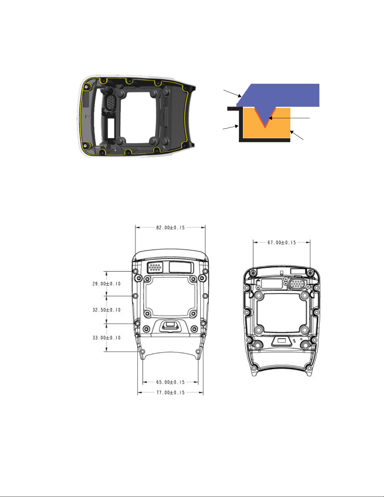
Chapter 5: Mechanical Considerations
Back Cover Modules and Devices
The following illustration indicates the ridge on the expansion back cover. This ridge is identical
on all back cover variants.
Figure 5.5 Sealing Ridge on Expansion Back Cover
Back cover modules are attached to the Omnii main housing with eight T10 Torx screws that enter
from the back, plus two T6 Torx screws that enter through the front of the unit above the display,
and fit into inserts mounted in the inside of the back cover module. Any back cover module
you design must have these eight screw holes and two inserts to secure the back cover to the
main housing.
Expansion
Device
Main
Housing
Ridge
Overmould
Figure 5.6 Location of Back Cover Mounting Points
Back Screw Holes Front Inserts
units = mm
72 Psion Teklogix Omnii HDK User Manual
Page 83

Chapter 5: Mechanical Considerations
Back Cover Modules and Devices
Installing Back Cover Modules
To remove the existing back cover:
1. If a pod expansion module is installed on the expansion back cover, it should be removed first:
a. Remove the four T10 Torx screws securing the pod to the main housing.
b. Lift the pod module from the unit.
c. Disconnect the flex cable from the pod expansion module.
2. Remove the eight T10 Torx screws holding the back cover to the main housing.
3. Remove the two T6 Torx screws at the top of the display on the front of the unit.
4. Gently lift the back cover from the main housing to allow access to the cables that are
still attached.
5. Disconnect any cables attaching the back cover to the main unit (trigger switch, scanner,
speaker, camera, GPS antenna are all possibilities).
6. Remove the back cover module.
To attach the new back cover module:
1. Connect any cables to the appropriate sockets on the main logic board and GPS module
(if installed).
2. Seat the back cover on the main housing.
3. Install eight M3x6 T10 Torx screws to secure the back cover to the main housing. Torque
the screws to 5.0 in-lb (0.56 N-m) in the sequence indicated below to ensure a consistent
seal around the perimeter.
6
7
3
2
1
4
8
5
4. Install two M2x8 T6 Torx screws in the two mounting points at the top of the display on
the front of the unit. Torque the screws to 2.5 in-lb (0.28 N-m).
Psion Teklogix Omnii HDK User Manual 73
Page 84

Chapter 5: Mechanical Considerations
Pistol Grip Modules
5.4.5 Pistol Grip Modules
This section describes the specifics of designing and mounting attachments to the pistol grip
mounting points on the back cover modules.
Table 5.11 Associated Files for Pistol Grips (Back Covers)
Description Filename
2D line drawings of the auto-range standard back cover with
locations of mounting points for the back cover and pistol grip
Back_Cover_Auto_Std_2D.dwg
Back_Cover_Auto_Std_2D.pdf
3D CAD models of the auto-range standard back cover Back_Cover_Auto_Std_3D.igs
Back_Cover_Auto_Std_3D.stp
2D line drawings of the expansion back cover with locations of
mounting points for the back cover, pistol grip, end-cap and
pod expansion
3D CAD models of the expansion back cover, showing end-cap
and pod expansion openings with sealing overmoulds, and
keep-away areas for camera and speaker options
2D line drawings of the large standard back cover with locations of mounting points for the back cover and pistol grip
Back_Cover_Expan_2D.dwg
Back_Cover_Expan_2D.pdf
Back_Cover_Expan_3D.igs
Back_Cover_Expan_3D.stp
Back_Cover_Large_Std_2D.dwg
Back_Cover_Large_Std_2D.pdf
3D CAD models of the large standard back cover Back_Cover_Large_Std_3D.igs
Back_Cover_Large_Std_3D.stp
Table 5.12 Required Fasteners
How Used Quantity Part Number Screw Size
Torque
(in-lb)
Bit
Pistol Grip to Main Housing 4 1005118 M3x6 5.0 Phillips
Figure 5.7 Location of Pistol Grip Mounting Points on Expansion Back Cover
units = mm
74 Psion Teklogix Omnii HDK User Manual
Page 85

5.4.6 Keyboard Modules
Custom keyboard overlays and hard caps may be developed for use on Omnii. The HDK provides
PDF files with details of the artwork that is used on the factory-installed components so that
the colours may be faithfully reproduced to maintain the contrast, visibility and overall look
of the unit.
5.4.6.1 Keyboard Overlays
This section describes the specifics of designing and installing new keyboard overlays on Omnii.
Table 5.13 Associated Files for Keyboard Overlays
Chapter 5: Mechanical Considerations
Keyboard Modules
Description Filename
Artwork for the 36-key, alpha modified, numeric calculator,
12 Fn keyboard overlay
Artwork for the 36-key numeric telephony, 12 Fn keyboard overlay KB_Overlay_36NumTel12.pdf
Artwork for the 59-key, alpha ABC, numeric telephony, 6 Fn
keyboard overlay
KB_Overlay_36ModNumCal12.pdf
KB_Overlay_59ABCTel6.pdf
The factory keyboard overlay may be replaced with a custom keyboard overlay. There are two
form factors of Omnii keyboards: a 36-key numeric format, and a 59-key full alphanumeric
format. Make sure you use the correct files and parts for your keyboard type.
You can install the custom overlay on an existing keyboard bezel, provided you first remove (peel
off) the factory-installed overlay. Clean the bezel surface thoroughly with isopropyl alcohol to
remove all traces of the old adhesive before installing the new overlay.
If you wish to install the overlay on a new keyboard bezel, or if you need to replace a damaged
bezel, blank ones can be ordered using the following part numbers:
Table 5.14 Blank Keyboard Bezel Part Numbers
Part Number Keyboard Bezel Form Factor
1004988 59-key alphanumeric
1004982 36-key numeric
5.4.6.2 Keyboard Hard Caps
This section describes the specifics of designing and installing new keyboard hard caps on Omnii.
Table 5.15 Associated Files for Keyboard Hard Caps
Artwork for the 36-key, alpha modified, numeric calculator,
12 Fn keyboard hard caps
Artwork for the 36-key numeric telephony, 12 Fn keyboard
hard caps
Artwork for the 59-key, alpha ABC, numeric telephony, 6 Fn
keyboard hard caps
Description Filename
KB_HardCaps_36ModNumCal12.pdf
KB_HardCaps_36NumTel12.pdf
KB_HardCaps_59ABCTel6.pdf
Psion Teklogix Omnii HDK User Manual 75
Page 86

Chapter 5: Mechanical Considerations
Installing Devices Inside Existing Modules
Installing new keyboard hard caps requires a new, clean, keyboard elastomer. You cannot remove
the hard caps from an existing elastomer to install new ones. Blank elastomers can be ordered
using the following part numbers:
Table 5.16 Blank Keyboard Elastomer Part Numbers
Part Number Keyboard Elastomer Form Factor
1004986 59-key alphanumeric
1004980 36-key numeric
5.5 Installing Devices Inside Existing Modules
Schematics and drawings are provided for the purpose of mounting custom devices inside existing
modules, including back covers, pod expansion modules and end-caps.
5.5.1 Standard Scanner Pod
The following files show the dimensions and contours of the standard scanner pod for the
expansion back cover:
Table 5.17 Associated Files for Standard Scanner Pod
Description Filename
2D line drawings of the standard scanner pod with locations of mounting
points for the pod and for the scanner assembly
3D CAD models of the standard scanner pod Scanner_Pod_Std_3D.igs
Scanner_Pod_Std_2D.dwg
Scanner_Pod_Std_2D.pdf
Scanner_Pod_Std_3D.stp
The following fasteners are required to secure the standard scanner pod to the expansion
back cover:
Table 5.18 Required Fasteners
How Used Quantity Part Number Screw Size
Scanner Pod to Expansion Back Cover 4 1005090 M3x5 5.0 T10
Torque
(in-lb)
To remove the existing scanner pod:
1. Remove the four T10 Torx screws securing the scanner pod to the main housing.
2. Lift the pod from the unit.
3. Disconnect the scanner flex cable from the scanner module.
To attach the new pod module:
Bit
1. Attach any cables to the appropriate sockets on the main logic board or GPS module
(if installed).
2. Seat the new pod module on the opening in the back cover.
3. Install four M3x5 T10 Torx screws to secure the scanner pod to the back cover. Torque the
screws to 5.0 in-lb (0.56 N-m).
76 Psion Teklogix Omnii HDK User Manual
Page 87

5.5.2 Large/Auto-Range Standard Back Covers
The following files show the dimensions and contours of the large and auto-range standard
back covers:
Table 5.19 Associated Files for Large Standard Back Cover
Description Filename
Chapter 5: Mechanical Considerations
Large/Auto-Range Standard Back Covers
2D line drawings of the auto-range standard back cover with locations
of mounting points for the back cover and pistol grip
3D CAD models of the auto-range standard back cover Back_Cover_Auto_Std_3D.igs
2D line drawings of the large standard back cover with locations of
mounting points for the back cover and pistol grip
3D CAD models of the large standard back cover Back_Cover_Large_Std_3D.igs
Back_Cover_Auto_Std_2D.dwg
Back_Cover_Auto_Std_2D.pdf
Back_Cover_Auto_Std_3D.stp
Back_Cover_Large_Std_2D.dwg
Back_Cover_Large_Std_2D.pdf
Back_Cover_Large_Std_3D.stp
The following fasteners are required to secure a standard back cover to the main housing:
Table 5.20 Required Fasteners
How Used Quantity Part Number Screw Size
Back Cover to Main Housing (Back) 8 1004948 M3x6 5.0 T10
Back Cover to Main Housing (Front) 2 1004946 M2x8 2.5 T6
Scanner Module to Back Cover 4 1004945 M2.5x5 2.5 T6
Torque
(in-lb)
Bit
To remove the standard back cover:
1. Remove the eight T10 Torx screws holding the back cover to the main housing.
2. Remove the two T6 Torx screws at the top of the display on the front of the unit.
3. Gently lift the back cover from the main housing to allow access to the cables that are
still attached.
4. Disconnect any cables attaching the back cover to the main unit.
5. Remove the back cover module.
6. If an existing scanner (or other) module is mounted in the back cover, remove the four T6
Torx screws holding the assembly to the back cover.
Insert the new module in the back cover, and secure using four M2.5x5 T6 Torx screws. Torque
the screws to 2.5 in-lb (0.28 N-m).
To attach the back cover to the main housing:
1. Attach any cables to the appropriate sockets on the main logic board.
2. Seat the back cover on the main housing.
Psion Teklogix Omnii HDK User Manual 77
Page 88

Chapter 5: Mechanical Considerations
End-Cap
3. Install eight M3x6 T10 Torx screws to secure the back cover to the main housing. Torque
the screws to 5.0 in-lb (0.56 N-m) in the sequence indicated below to ensure a consistent
seal around the perimeter.
4. Install two M2x8 T6 Torx screws in the two mounting points at the top of the display on
the front of the unit. Torque the screws to 2.5 in-lb (0.28 N-m).
5.5.3 End-Cap
The following files show the dimensions and contours of the standard and GPS end-caps:
Table 5.21 Associated Files for Large Integrated Back Cover
2D line drawings of the end-cap with GPS antenna Endcap_GPS_2D.dwg
3D CAD models of the end-cap with GPS antenna Endcap_GPS_3D.igs
6
7
Description Filename
3
2
1
4
8
5
Endcap_GPS_2D.pdf
Endcap_GPS_3D.stp
2D line drawings of the standard end-cap Endcap_Standard_2D.dwg
Endcap_Standard_2D.pdf
3D CAD model of the standard end-cap Endcap_Standard_3D.stp
The following fasteners are required to secure an end-cap to the standard back cover:
Table 5.22 Required Fasteners
How Used Quantity Part Number Screw Size
End-Cap Module to Main Housing 4 1005090 M3x5 5.0 T10
Torque
(in-lb)
Bit
To remove the existing end-cap:
1. If the existing end-cap contains a module connected to the main unit (such as the end-cap with
GPS antenna), you must first remove the back cover of your Omnii:
a. Remove the eight T10 Torx screws holding the back cover to the main housing.
b. Remove the two T6 Torx screws at the top of the display on the front of the unit.
c. Gently lift the back cover from the main housing to allow access to the cables that are
still attached.
d. Disconnect any cables attaching the back cover and end-cap to the main unit.
78 Psion Teklogix Omnii HDK User Manual
Page 89

Chapter 5: Mechanical Considerations
End-Cap
2. Remove the four Torx screws securing the end-cap to the main housing.
3. Gently pull the end-cap away from the main housing.
To attach the new pod module:
1. Route the cable for the end-cap module through the opening in the top of the unit, and connect
to the appropriate socket on the main unit.
2. Fit the new end-cap module into place on the main housing, being careful not to catch the
cable in the seal.
3. Install four M3x5 T10 Torx screws to secure the end-cap to the main housing. Torque the
screws to 5.0 in-lb (0.56 N-m).
4. Replace the back cover.
a. Attach any back cover cables to the appropriate sockets on the main logic board.
b. Seat the back cover in place on the main housing.
c. Install eight M3x6 T10 Torx screws to secure the back cover to the main housing. Torque
the screws to 5.0 in-lb (0.56 N-m) in the sequence indicated below to ensure a consistent
seal around the perimeter.
6
7
3
2
1
4
8
5
d. Install two M2x8 Torx screws in the two mounting points at the top of the display on the
front of the unit. Torque the screws to 2.5 in-lb (0.28 N-m).
Psion Teklogix Omnii HDK User Manual 79
Page 90

Page 91

OMNII EXPANSION PORTS AND CONNECTORS 6
6.1 Overview . . . . . . . . . . . . . . . . . . . . . . . . . . . . . . . . . . . . . . . . . . . . . . . . . 83
6.2 Connector Locations . . . . . . . . . . . . . . . . . . . . . . . . . . . . . . . . . . . . . . . . . . . 83
6.3 Audio Connector . . . . . . . . . . . . . . . . . . . . . . . . . . . . . . . . . . . . . . . . . . . . . 84
6.3.1 Audio Reference Designs . . . . . . . . . . . . . . . . . . . . . . . . . . . . . . . . . . . 86
6.3.1.1 Single-Ended Headset. . . . . . . . . . . . . . . . . . . . . . . . . . . . . . . . . 86
6.3.1.2 Push-to-Talk Handset . . . . . . . . . . . . . . . . . . . . . . . . . . . . . . . . . 88
6.3.1.3 External Speaker . . . . . . . . . . . . . . . . . . . . . . . . . . . . . . . . . . . 90
6.4 Expansion Ports . . . . . . . . . . . . . . . . . . . . . . . . . . . . . . . . . . . . . . . . . . . . . 90
6.4.1 Expansion Port Power . . . . . . . . . . . . . . . . . . . . . . . . . . . . . . . . . . . . . 91
6.4.2 Expansion Port 1 (End-Cap Connector) . . . . . . . . . . . . . . . . . . . . . . . . . . . . 94
6.4.3 Expansion Port 2 (Pod Expansion Connector) . . . . . . . . . . . . . . . . . . . . . . . . . 96
6.4.4 Expansion Port 3 (100-pin Multi-Function Connector) . . . . . . . . . . . . . . . . . . . . 98
6.4.5 Expansion Port Standard Interfaces . . . . . . . . . . . . . . . . . . . . . . . . . . . . . . 100
6.4.5.1 Serial (UART) Interface. . . . . . . . . . . . . . . . . . . . . . . . . . . . . . . . 100
6.4.5.2 USB Interface . . . . . . . . . . . . . . . . . . . . . . . . . . . . . . . . . . . . . 101
6.4.5.3 GPIO (General Purpose Input/Output) Interface . . . . . . . . . . . . . . . . . . . 101
6.4.5.4 SPI (Serial Peripheral Interface) . . . . . . . . . . . . . . . . . . . . . . . . . . . 102
6.5 100-Pin Multi-Function Connector. . . . . . . . . . . . . . . . . . . . . . . . . . . . . . . . . . . . 102
Psion Teklogix Omnii HDK User Manual 81
Page 92

Page 93

6.1 Overview
This chapter describes the Omnii connectors used for attaching expansion devices to the handheld computer.
6.2 Connector Locations
Omnii has the following physical connectors located on the main logic board:
• Audio expansion connector (J4).
• End-cap connector / Expansion Port 1 (J6).
• Pod expansion connector / Expansion Port 2 (J10).
• 100-pin multi-function connector, includes Expansion Port 3 (J2).
• Camera connector (J9) (not for use with Omnii XT10 HDK).
• Scanner/imager connector (J13) (not for use with Omnii XT10 HDK).
Figure 6.1 Connector Locations on the Omnii Main Logic Board
Chapter 6: Omnii Expansion Ports and Connectors
Overview
J13
J6
J10
J4
J9
J2
If a GPS module is installed, it will occupy the 100-pin connector. However, the unused pins are
passed through to connectors on the back of the module, so they are still available for other
devices. The connectors on the back of the GPS module provide access to:
• Proprietary interface pins reserved for future use (J1).
• Expansion Port 3 (J3). This connector is identical to the pod expansion connector (expansion
port 2) on the main logic board.
Psion Teklogix Omnii HDK User Manual 83
Page 94
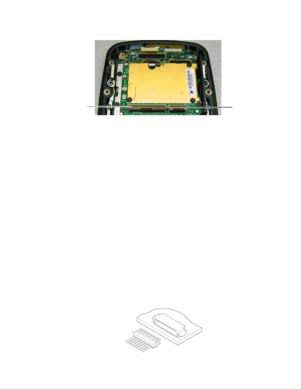
Chapter 6: Omnii Expansion Ports and Connectors
Audio Connector
Figure 6.2 Connector Locations on the GPS Module
J1
6.3 Audio Connector
Theory of Operation
The Omnii main logic board exposes a 16-pin audio connector, providing a means of connecting
audio input and output devices such as headsets, push-to-talk handsets and external speakers.
Included in the expansion interface are the following connections:
• HPL and HPR: left and right audio outputs (Headphone Left and Headphone Right)
• HP_AMP_EN: enable line for headphone amplifier circuit
• HP_DETECT_N: headset detection
• MIC+ and MIC-: differential audio inputs from expansion board into main logic board
• MIC_AMP_EN: enable line for microphone amplifier and biasing circuitry
• PTT_DETECT: detection of push-to-talk switch
• SPKR_EXP_R and SPKR_EXP_R+: differential audio outputs for driving a
loudspeaker (4 or 8 Ohms)
Audio Connector Details
The audio connector is a side-entry 0.8 mm pitch disconnectable insulation
displacement connector.
J3
Manufacturer: JST
Manufacturer Part Number: SM16B-SURS-TF(LF)(SN)
Mating Connector: 16SUR-32S
Number of Pins: 16
Current Rating: 0.5 A per pin for 32 AWG wire
Figure 6.3 Diagram of JST Audio Connector
84 Psion Teklogix Omnii HDK User Manual
(do not use 36 AWG wire)
Page 95

Chapter 6: Omnii Expansion Ports and Connectors
Audio Connector
Pinout
Table 6.1 Pinout of 16-pin Audio Connector
Direction
Pin Name
1, 2 3V3 Output Power 3.3 V supply input into audio expansion
3, 4, 7, 10 GND Ground Ground Ground signal connected to ground plane on the
5 SPKR_EXP_R+ Output Analog Bridge tied load (BTL) audio signals from class
6 SPKR_EXP_R-
8 HPL Output Analog Left headphone signal from audio codec on
9 HPR Output Analog Right headphone signal from audio codec on
(referenced
to MLB)
Type Function
main logic board
D amplifier on MLB to drive a loudspeaker.
Designed to drive a load down to a minimum of
4 Ohms. Capable of driving up to 510 mW into
an 8 Ohm speaker with 1% THD.
MLB. Capable of driving from -3.3 V to +3.3 V.
Biased at 0 V.
MLB. Capable of driving from -3.3 V to +3.3 V.
Biased at 0 V.
11 MIC+ Input Analog Differential microphone signals coming from
12 MIC-
expansion board. These inputs are fed into the
codec on the main logic board. Maximum input
level of each of these signals is 0.50 VRMS.
The codec applies its own bias voltage on these
signals and therefore they need to be AC
coupled on the expansion board.
13 HP_AMP_EN Output Digital Active-high signal to enable headphone ampli-
fier when headphones are in use. 1.8 V signal
coming from the main logic board.
14 MIC_AMP_EN Output Digital Active-high signal to enable microphone
preamplifier and/or biasing circuitry when
microphone is in use. 1.8 V signal coming from
the main logic board.
15 HP_DETECT Input Digital Active-low signal when a headset is plugged
into the expansion board. 1.8 V signal.
100 kohm pull-up resistor on the main
logic board.
16 PTT_DETECT Input Digital Active-low signal when a push-to-talk micro-
phone is enabled. Enables reading of the MIC
lines when active. A 100 kohm pull-up resistor
to 1.8 V is placed on the MLB.
Psion Teklogix Omnii HDK User Manual 85
Page 96

Chapter 6: Omnii Expansion Ports and Connectors
Audio Reference Designs
Figure 6.4 Pin Diagram of 16-pin Audio Expansion
6.3.1 Audio Reference Designs
Three sample reference designs are included in the files for the Omnii HDK. There are sample
designs for a single-ended headset, a push-to-talk handset and an external speaker.
Table 6.2 Audio Reference Design Files
Description Filename
Reference design for a single-ended headset Audio_Single-Ended_Headset.pdf
Reference design for a push-to-talk handset Audio_PTT.pdf
Reference design for an external speaker Audio_External_Speaker.pdf
The designs are examined in detail in the following sections to demonstrate how to design
modules that connect to the audio expansion interface connector.
6.3.1.1 Single-Ended Headset
The single-ended headset audio expansion board can be used with most commercially available
2.5 mm audio headsets. The MAX9720 headphone amplifier in the reference design will detect
whether a mono or stereo headset has been inserted and adjust the output signals accordingly.
To prevent GSM interference in the 850/900/1800/1900 MHz bands from coupling into the audio
path and demodulating into the audio band, 33 pF and 10 pF capacitors are placed at various
locations throughout the circuit.
86 Psion Teklogix Omnii HDK User Manual
Page 97

Chapter 6: Omnii Expansion Ports and Connectors
Figure 6.5 Block Diagram of the Single-Ended Headset Expansion Board
Headphone Amplifier
Audio Reference Designs
The headphone amplifier is used to drive the speakers in the headset. It is only enabled when a
headset is plugged into the audio jack and the HP_AMP_EN signal is asserted. Additionally,
the MAX9720 headphone amplifier has automatic mono/stereo detection. In the event that a
mono headset is plugged in, the amplifier will automatically reroute its audio inputs to a single
output channel.
Microphone Biasing
The headset microphone is biased at 3.0 V when in use. It is biased from a low noise, low drop-out
linear regulator (LDO). When the microphone is not in use, the LDO is disabled and the biasing
is removed.
2.5 mm Audio Jack
The 2.5 mm audio jack can be used with a single-ended mono, or stereo, headset. When
the headset connector is inserted into the jack, the HP_DETECT line drops low. Without the
HP_DETECT signal, audio will not be routed to/from the audio expansion board. The figure
below illustrates the necessary connections on standard commercial stereo and mono audio plugs
that will allow them to interface with the audio jack in the reference design.
Figure 6.6 2.5 mm Single-Ended Headset Audio Jack Connection Diagram
Psion Teklogix Omnii HDK User Manual 87
Page 98

Chapter 6: Omnii Expansion Ports and Connectors
Audio Reference Designs
6.3.1.2 Push-to-Talk Handset
The push-to-talk handset reference design uses a 3.5 mm audio jack to accept a variety of push-totalk handsets with a differentially driven loudspeaker. These handsets have a switch which
enables/disables the microphone in the handset allowing audio to be played through the handset
while the microphone is disabled. To speak, the user pushes the switch enabling the microphone.
Audio output is driven from a class D amplifier on the main logic board which provides sufficient
power to drive the loudspeaker.
Similar to the single-ended headset audio expansion board, filtering capacitors are placed at
various locations throughout the audio paths to prevent GSM interference from coupling in. As
well, the microphone biasing and signal conversion is performed identically to the single-ended
headset reference design.
If a push-to-talk radio with a different activation scheme is used, a different detection circuit will
need to be designed.
Figure 6.7 Block Diagram of the Push-to-Talk Handset Expansion Board
3.5 mm Audio Jack
The reference design for a push-to-talk audio expansion board has a 3.5 mm audio jack which
provides connections to a single-ended microphone and a differentially driven loudspeaker. This is
the only connector configuration supported in the reference design.
88 Psion Teklogix Omnii HDK User Manual
Page 99

Chapter 6: Omnii Expansion Ports and Connectors
Audio Reference Designs
Figure 6.8 3.5 mm Push-to-Talk Handset Audio Jack Connection Diagram
Push-to-Talk Switch Detection
Push-to-talk handsets provide a switch to the user which will enable the microphone when pushed,
otherwise leaving the microphone deactivated. The PTT Switch Detection will generate an active
low signal when the switch is pressed. In the reference design, this is accomplished with a
comparator. When the switch is not pressed, the microphone is not connected and the DC voltage
applied at the microphone matches the 3.0 V biasing voltage. When the switch is pressed, the
microphone will draw some current, lowering the applied bias voltage below 3.0 V. A comparator
with hysteresis is used to toggle the PTT_DETECT signal.
Table 6.3 Comparator Thresholds and Hysteresis for PTT_DETECT
Condition
Minimum (V) Typical (V) Maximum (V)
PTT_DETECT
Falling Edge
PTT_DETECT
Rising Edge
Figure 6.9 Push-to-Talk Handset Switch Operation
Comparator Input Thresholds
2.77 2.81 2.86
2.70 2.75 2.80
Psion Teklogix Omnii HDK User Manual 89
Page 100
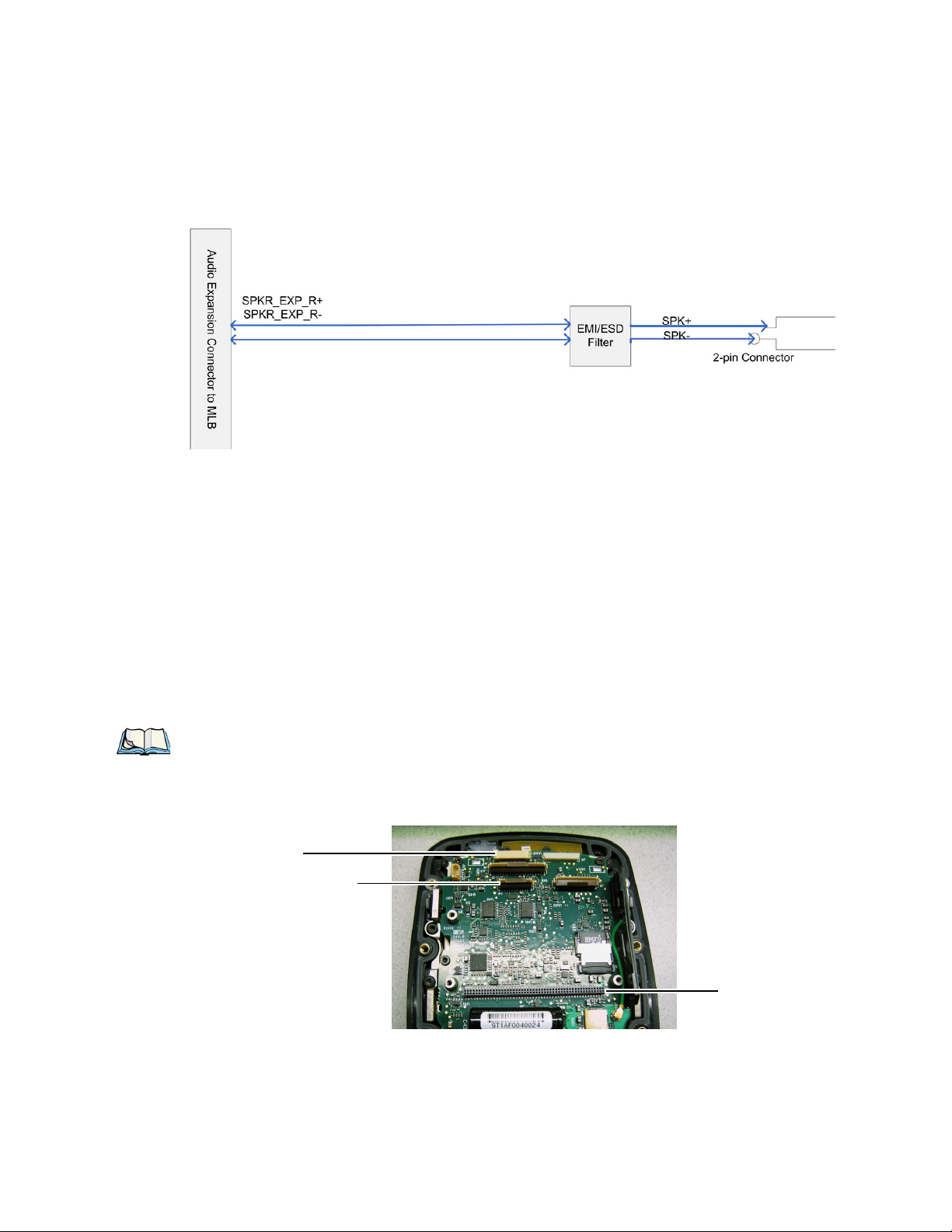
Chapter 6: Omnii Expansion Ports and Connectors
Expansion Ports
6.3.1.3 External Speaker
This reference design provides support for a loudspeaker attached through an audio expansion
board. This design is identical to the push-to-talk configuration, without support for
microphone input.
Figure 6.10 Block Diagram of the External Speaker Expansion Board
6.4 Expansion Ports
Omnii includes three designated “expansion ports” that expose standard GPIO, serial and USB
interfaces for expansion modules. Each expansion port operates independently of the other two,
allowing up to three expansion modules to be connected at the same time.
The three expansion ports are located as follows:
• Expansion Port 1: End-Cap Connector (see Section 6.4.2: “Expansion Port 1 (End-Cap
Connector)”)
• Expansion Port 2: Pod Expansion Connector (see Section 6.4.3: “Expansion Port 2 (Pod
Expansion Connector)”)
• Expansion Port 3: Multi-Function 100-Pin Connector (see Section 6.4.4: “Expansion Port 3
(100-pin Multi-Function Connector)”)
Note: If a GPS/WWAN module is installed in the 100-pin socket, the pins for expansion port 3 are
passed through to a 22-pin connector on the back of the module. In this case, the pinout for
expansion port 3 is the same as for expansion port 2.
Figure 6.11 Location of Expansion Ports on Omnii Main Logic Board
Expansion
Port 1
Expansion
Port 2
Expansion
Port 3
90 Psion Teklogix Omnii HDK User Manual
 Loading...