

Page 1

Print Servers
Wired/Wireless
User Guide
P1043301-006
Page 2

© 2017 ZIH Corp. The copyrights in this manual and the software and/or firmware in the label printer described
therein are owned by ZIH Corp. Unauthorized reproduction of this manual or the software and/or firmware in the
label printer may result in imprisonment of up to one year and fines of up to $10,000 (17
violators may be subject to civil liability.
This product may contain ZPL®, ZPL II®, and ZebraLink™ programs; Element Energy Equalizer® Circuit; E3®; and
Monotype Imaging fonts. Software © ZIH Corp. All rights reserved worldwide.
U.S.C.506). Copyright
ZebraLink and all product names and numbers are trademarks, and Zebra, the Zebra logo, ZPL, ZPL II, Element
Energy Equalizer Circuit, and E
All other brand names, product names, or trademarks belong to their respective holders. For additional trademark
information, please see “Trademarks” on the product CD.
3
Circuit are registered trademarks of ZIH Corp. All rights reserved worldwide.
Proprietary Statement This manual contains proprietary information of Zebra Technologies Corporation and its
subsidiaries (“Zebra Technologies”). It is intended solely for the information and use of parties operat ing and
maintaining the equipment described herein. Such proprietary information may not be used, reproduced, or disclosed
to any other parties for any other purpose without the express, written permission of Zebra Technologies Corporation.
Product Improvements Continuous improvement of products is a policy of Zebra Technologies Corporation.
All specifications and designs are subject to change without notice.
Liability Disclaimer Zebra Technologies Corporation takes steps to ensure that its published Engineering
specifications and manuals are correct; however, errors do occur. Zebra Technologies Corporation reserves the right
to correct any such errors and disclaims liability resulting therefrom.
Limitation of Liability In no event shall Zebra Technologies Corporation or anyone else involved in the creation,
production, or delivery of the accompanying product (including hard ware and software) be liab le for any damages
whatsoever (including, without limitation, consequential damages including loss of busin ess profi ts, business
interruption, or loss of business information) arising out of the use of, the results of use of, or inability to use such
product, even if Zebra Technologies Corporation has been advised of the possibility of such damages. Some
jurisdictions do not allow the exclusion or limitation of incidental or consequential damages, so the above limitation
or exclusion may not apply to you.
Part Number: P1043301-006
Page 3

Contents
Introduction . . . . . . . . . . . . . . . . . . . . . . . . . . . . . . . . . . . . . . . . . . . . . . . 7
Overview . . . . . . . . . . . . . . . . . . . . . . . . . . . . . . . . . . . . . . . . . . . . . . . . . . . . . .8
Support . . . . . . . . . . . . . . . . . . . . . . . . . . . . . . . . . . . . . . . . . . . . . . . . . . . . . . .8
Browser Requirements . . . . . . . . . . . . . . . . . . . . . . . . . . . . . . . . . . . . . . . .8
Supported Services . . . . . . . . . . . . . . . . . . . . . . . . . . . . . . . . . . . . . . . . . . .8
Address Administration Protocols . . . . . . . . . . . . . . . . . . . . . . . . . . . . . . . .8
Supported Wireless Radio Cards . . . . . . . . . . . . . . . . . . . . . . . . . . . . . . . .9
Supported Security Types . . . . . . . . . . . . . . . . . . . . . . . . . . . . . . . . . . . . .10
Printer Requirements . . . . . . . . . . . . . . . . . . . . . . . . . . . . . . . . . . . . . . . . . . .14
Hardware—Wired Print Servers . . . . . . . . . . . . . . . . . . . . . . . . . . . . . . . .14
Hardware—Wireless Print Servers . . . . . . . . . . . . . . . . . . . . . . . . . . . . . .15
Memory Requirements . . . . . . . . . . . . . . . . . . . . . . . . . . . . . . . . . . . . . . .16
Firmware—10/100 Print Server . . . . . . . . . . . . . . . . . . . . . . . . . . . . . . . . .17
Firmware—Wireless . . . . . . . . . . . . . . . . . . . . . . . . . . . . . . . . . . . . . . . . .18
Compatibility . . . . . . . . . . . . . . . . . . . . . . . . . . . . . . . . . . . . . . . . . . . . . . . . . .19
Specifications . . . . . . . . . . . . . . . . . . . . . . . . . . . . . . . . . . . . . . . . . . . . . . . . .19
External 10/100 Print Server Specifications . . . . . . . . . . . . . . . . . . . . . . .19
Internal Print Server Specifications . . . . . . . . . . . . . . . . . . . . . . . . . . . . . .20
Wireless Print Server Specifications . . . . . . . . . . . . . . . . . . . . . . . . . . . . .21
Installation . . . . . . . . . . . . . . . . . . . . . . . . . . . . . . . . . . . . . . . . . . . . . . . 23
External 10/100 Print Server . . . . . . . . . . . . . . . . . . . . . . . . . . . . . . . . . . . . . .24
Before You Begin . . . . . . . . . . . . . . . . . . . . . . . . . . . . . . . . . . . . . . . . . . .24
Illustration . . . . . . . . . . . . . . . . . . . . . . . . . . . . . . . . . . . . . . . . . . . . . . . . .25
Installation Instructions . . . . . . . . . . . . . . . . . . . . . . . . . . . . . . . . . . . . . . .26
Internal 10/100 Print Server . . . . . . . . . . . . . . . . . . . . . . . . . . . . . . . . . . . . . .27
Wireless Print Servers . . . . . . . . . . . . . . . . . . . . . . . . . . . . . . . . . . . . . . . . . . .27
10/12/17 P1043301-006
Page 4

4
Contents
Install a Radio Card in a Wireless Print Server . . . . . . . . . . . . . . . . . . . . . . . .27
Wireless Radio Card . . . . . . . . . . . . . . . . . . . . . . . . . . . . . . . . . . . . . . . . .27
Compact Flash Wireless Radio Card . . . . . . . . . . . . . . . . . . . . . . . . . . . .29
Getting Started . . . . . . . . . . . . . . . . . . . . . . . . . . . . . . . . . . . . . . . . . . . 31
Before You Begin . . . . . . . . . . . . . . . . . . . . . . . . . . . . . . . . . . . . . . . . . . . . . .33
Default User ID and Password . . . . . . . . . . . . . . . . . . . . . . . . . . . . . . . . .33
Printing a Configuration Label— External 10/100 Print Server . . . . . . . . . . . .34
Printing a Network Configuration Label . . . . . . . . . . . . . . . . . . . . . . . . . . . . . .36
Configuration of Wireless Securities . . . . . . . . . . . . . . . . . . . . . . . . . . . . . . . .40
View Wireless Status through the Control Panel . . . . . . . . . . . . . . . . . . . . . . .41
LCD Link Status and Wireless Signal Indicators (Other Printers) . . . . . . .42
HC100 Wireless Status Indicator Lights . . . . . . . . . . . . . . . . . . . . . . . . . .43
Network Status Indicator Lights . . . . . . . . . . . . . . . . . . . . . . . . . . . . . . . .44
Determining the Active Print Server . . . . . . . . . . . . . . . . . . . . . . . . . . . . . . . .45
Viewing IP Addresses and the Active Print Server . . . . . . . . . . . . . . . . . .45
Active Device Selection . . . . . . . . . . . . . . . . . . . . . . . . . . . . . . . . . . . . . . .46
Assigning an IP Address on any Print Server . . . . . . . . . . . . . . . . . . . . . . . . .48
With Dynamic Host Configuration Protocol (DHCP) . . . . . . . . . . . . . . . . .48
Assigning an IP Address Without DHCP via ZebraNet Bridge . . . . . . . . .48
Assigning an IP address Without DHCP from the Control Panel . . . . . . .48
Assigning an IP Address Without DHCP via a Telnet Session . . . . . . . . .49
Setting and Monitoring Alerts on Any Print Server . . . . . . . . . . . . . . . . . . . . .51
Using ZebraNet Bridge . . . . . . . . . . . . . . . . . . . . . . . . . . . . . . . . . . . . . . .51
ZebraLink Alerts . . . . . . . . . . . . . . . . . . . . . . . . . . . . . . . . . . . . . . . . . . . .51
Using WebView . . . . . . . . . . . . . . . . . . . . . . . . . . . . . . . . . . . . . . . . . . . . .53
Checking Print Server Configuration Settings . . . . . . . . . . . . . . . . . . . . . . . . .56
Using ZebraNet Bridge . . . . . . . . . . . . . . . . . . . . . . . . . . . . . . . . . . . . . . .56
Using WebView . . . . . . . . . . . . . . . . . . . . . . . . . . . . . . . . . . . . . . . . . . . . .56
Enabling Protocols . . . . . . . . . . . . . . . . . . . . . . . . . . . . . . . . . . . . . . . . . . . . .59
Using WebView . . . . . . . . . . . . . . . . . . . . . . . . . . . . . . . . . . . . . . . . . . . . .59
Defaulting ALL Print Servers . . . . . . . . . . . . . . . . . . . . . . . . . . . . . . . . . . . . . .61
Using WebView . . . . . . . . . . . . . . . . . . . . . . . . . . . . . . . . . . . . . . . . . . . . .61
Using ZebraNet Bridge . . . . . . . . . . . . . . . . . . . . . . . . . . . . . . . . . . . . . . .63
Using a ZPL Command . . . . . . . . . . . . . . . . . . . . . . . . . . . . . . . . . . . . . . .63
Defaulting a 10/100 Print Server . . . . . . . . . . . . . . . . . . . . . . . . . . . . . . . .63
Defaulting the Print Servers on the LP/TLP 2824 Plus and G-Series Printers
64
Defaulting the Print Servers on the HC100 Printers . . . . . . . . . . . . . . . . .64
Defaulting the Print Servers on the ZM400 and ZM600 Printers . . . . . . .64
Defaulting the Print Servers on 105SL, PAX4, Xi4, ZE500, and 105SLPlus
Printers . . . . . . . . . . . . . . . . . . . . . . . . . . . . . . . . . . . . . . . . . . . . . . . . . . .65
Defaulting the Print Servers on the ZD400, ZD500R, and ZTxxx Printers 65
P1043301-006 10/12/17
Page 5

Contents
Printing Queues . . . . . . . . . . . . . . . . . . . . . . . . . . . . . . . . . . . . . . . . . . . 67
Berkeley Software Distribution (BSD)-Style Print Queue . . . . . . . . . . . . . . . .68
Configuring the Print Queue . . . . . . . . . . . . . . . . . . . . . . . . . . . . . . . . . . .68
System V Queue Installation . . . . . . . . . . . . . . . . . . . . . . . . . . . . . . . . . . . . . .69
Configuring Operating System V Queue for Printing . . . . . . . . . . . . . . . .69
Prerequisites . . . . . . . . . . . . . . . . . . . . . . . . . . . . . . . . . . . . . . . . . . . . . . .69
UNIX Configuration . . . . . . . . . . . . . . . . . . . . . . . . . . . . . . . . . . . . . . . . . .69
Using Printing Protocols . . . . . . . . . . . . . . . . . . . . . . . . . . . . . . . . . . . 71
IPP . . . . . . . . . . . . . . . . . . . . . . . . . . . . . . . . . . . . . . . . . . . . . . . . . . . . . . . . . .72
FTP . . . . . . . . . . . . . . . . . . . . . . . . . . . . . . . . . . . . . . . . . . . . . . . . . . . . . . . . .73
ZebraLink WebView . . . . . . . . . . . . . . . . . . . . . . . . . . . . . . . . . . . . . . . 75
WebView . . . . . . . . . . . . . . . . . . . . . . . . . . . . . . . . . . . . . . . . . . . . . . . . . . . . .76
Home Page . . . . . . . . . . . . . . . . . . . . . . . . . . . . . . . . . . . . . . . . . . . . . . . .76
View Printer Configuration . . . . . . . . . . . . . . . . . . . . . . . . . . . . . . . . . . . .78
View and Modify Printer Settings . . . . . . . . . . . . . . . . . . . . . . . . . . . . . . .80
Network Communications Screens . . . . . . . . . . . . . . . . . . . . . . . . . . . . . . . . .86
Directory Listing . . . . . . . . . . . . . . . . . . . . . . . . . . . . . . . . . . . . . . . . . . . .93
Printer Controls . . . . . . . . . . . . . . . . . . . . . . . . . . . . . . . . . . . . . . . . . . . . .97
5
Print Server Web Pages . . . . . . . . . . . . . . . . . . . . . . . . . . . . . . . . . . . . 99
Status and Configuration . . . . . . . . . . . . . . . . . . . . . . . . . . . . . . . . . . . . .100
Print Server Status . . . . . . . . . . . . . . . . . . . . . . . . . . . . . . . . . . . . . . . . .107
View Port Status . . . . . . . . . . . . . . . . . . . . . . . . . . . . . . . . . . . . . . . . . . .109
Reset . . . . . . . . . . . . . . . . . . . . . . . . . . . . . . . . . . . . . . . . . . . . . . . . . . . .110
Restore . . . . . . . . . . . . . . . . . . . . . . . . . . . . . . . . . . . . . . . . . . . . . . . . . .111
Control Panel . . . . . . . . . . . . . . . . . . . . . . . . . . . . . . . . . . . . . . . . . . . . 113
Control Panel Menu Options . . . . . . . . . . . . . . . . . . . . . . . . . . . . . . . . . . . . .114
Wired Network Parameters on the Printer Display . . . . . . . . . . . . . . . . .114
Wireless Network Parameters on the Printer Display . . . . . . . . . . . . . . .116
Hardware T roubleshooting . . . . . . . . . . . . . . . . . . . . . . . . . . . . . . . . . 119
Troubleshooting the External 10/100 Print Server . . . . . . . . . . . . . . . . . . . .120
Resetting to Factory Defaults . . . . . . . . . . . . . . . . . . . . . . . . . . . . . . . . .120
External 10/100 Print Server Network Status and Status Indicators . . . . 120
Troubleshooting the External 10/100 Print Server . . . . . . . . . . . . . . . . .121
Troubleshooting the Internal Print Server . . . . . . . . . . . . . . . . . . . . . . . . . . .123
Resetting the Internal Print Server to Factory Defaults . . . . . . . . . . . . . .123
Internal Print Server Network Status and Activity Indicators . . . . . . . . . .123
Troubleshooting the Wireless Print Server . . . . . . . . . . . . . . . . . . . . . . . . . .125
Print Server Will Not Operate on the 5Ghz Band . . . . . . . . . . . . . . . . . .125
Resetting the Wireless Print Server to Factory Defaults . . . . . . . . . . . . .125
10/12/17 P1043301-006
Page 6

6
Contents
ZebraNet Bridge Discovery or Configuration Problems . . . . . . . . . . . . . . . .126
Unable to Print . . . . . . . . . . . . . . . . . . . . . . . . . . . . . . . . . . . . . . . . . . . . . . .126
Ping the Printer . . . . . . . . . . . . . . . . . . . . . . . . . . . . . . . . . . . . . . . . . . . .127
Telnet . . . . . . . . . . . . . . . . . . . . . . . . . . . . . . . . . . . . . . . . . . . . . . . . . . . .127
Unable to Configure Device . . . . . . . . . . . . . . . . . . . . . . . . . . . . . . . . . . . . .128
HP JetAdmin or HP Web JetAdmin . . . . . . . . . . . . . . . . . . . . . . . . . . . . . . . .128
Wireless Error Messages . . . . . . . . . . . . . . . . . . . . . . . . . . . . . . . . . . . . . . .128
General Wireless Issues . . . . . . . . . . . . . . . . . . . . . . . . . . . . . . . . . . . . . . . .129
Encryption and Authentication Issues . . . . . . . . . . . . . . . . . . . . . . . . . . . . . .131
IP Issues . . . . . . . . . . . . . . . . . . . . . . . . . . . . . . . . . . . . . . . . . . . . . . . . . . . .132
Frequently Asked Questions . . . . . . . . . . . . . . . . . . . . . . . . . . . . . . . 133
FAQs . . . . . . . . . . . . . . . . . . . . . . . . . . . . . . . . . . . . . . . . . . . . . . . . . . . . . . .133
Glossary . . . . . . . . . . . . . . . . . . . . . . . . . . . . . . . . . . . . . . . . . . . . . . . . 137
Index . . . . . . . . . . . . . . . . . . . . . . . . . . . . . . . . . . . . . . . . . . . . . . . . . . . 143
P1043301-006 10/12/17
Page 7

1
Introduction
This chapter provides a high-level overview of Zebra’s wired and wireless print servers,
installation types, standard network configurations, and how to work with the print servers.
Contents
Overview . . . . . . . . . . . . . . . . . . . . . . . . . . . . . . . . . . . . . . . . . . . . . . . . . . . . . . . . . . . . . . 8
Support. . . . . . . . . . . . . . . . . . . . . . . . . . . . . . . . . . . . . . . . . . . . . . . . . . . . . . . . . . . . . . . . 8
Browser Requirements . . . . . . . . . . . . . . . . . . . . . . . . . . . . . . . . . . . . . . . . . . . . . . . . . 8
Supported Services . . . . . . . . . . . . . . . . . . . . . . . . . . . . . . . . . . . . . . . . . . . . . . . . . . . . 8
Address Administration Protocols . . . . . . . . . . . . . . . . . . . . . . . . . . . . . . . . . . . . . . . . . 8
Supported Wireless Radio Cards. . . . . . . . . . . . . . . . . . . . . . . . . . . . . . . . . . . . . . . . . . 9
Supported Security Types . . . . . . . . . . . . . . . . . . . . . . . . . . . . . . . . . . . . . . . . . . . . . . 10
Printer Requirements. . . . . . . . . . . . . . . . . . . . . . . . . . . . . . . . . . . . . . . . . . . . . . . . . . . . 14
Hardware—Wired Print Servers. . . . . . . . . . . . . . . . . . . . . . . . . . . . . . . . . . . . . . . . . . 14
Hardware—Wireless Print Servers . . . . . . . . . . . . . . . . . . . . . . . . . . . . . . . . . . . . . . . 15
Memory Requirements. . . . . . . . . . . . . . . . . . . . . . . . . . . . . . . . . . . . . . . . . . . . . . . . . 16
Firmware—10/100 Print Server . . . . . . . . . . . . . . . . . . . . . . . . . . . . . . . . . . . . . . . . . . 17
Firmware—Wireless. . . . . . . . . . . . . . . . . . . . . . . . . . . . . . . . . . . . . . . . . . . . . . . . . . . 18
Compatibility. . . . . . . . . . . . . . . . . . . . . . . . . . . . . . . . . . . . . . . . . . . . . . . . . . . . . . . . . . . 19
External 10/100 Print Server Specifications. . . . . . . . . . . . . . . . . . . . . . . . . . . . . . . . . . . 19
External 10/100 Print Server Specifications. . . . . . . . . . . . . . . . . . . . . . . . . . . . . . . . . 19
Internal Print Server Specifications . . . . . . . . . . . . . . . . . . . . . . . . . . . . . . . . . . . . . . . 20
Wireless Print Server Specifications . . . . . . . . . . . . . . . . . . . . . . . . . . . . . . . . . . . . . . 21
10/12/17 P1043301-006
Page 8

Introduction
8
Overview
Overview
Support
Browser Requirements
The print server is an optional factory- or field-installed device that connects the network and
your ZebraLink-enabled printer. The print server provides you with a web browser as a user
interface for printer and print server settings. If you use ZebraNet Bridge Enterprise, you can
easily access the specialized features of a ZebraLink-ena bl ed prin ter. For details, see the
ZebraNet Bridge Enterprise User Guide.
Note • You can download the most recent version of ZebraNet Bridge Enterprise from
www.zebra.com/utilities.
This section lists the minimum requirem ents for print servers, which include browsers,
supported services, address administration protocols, hardware, and firmware.
• HTML v3.2 or higher
• Internet Explorer
Supported Services
• Raw TCP • FTP
• HTTP • UDP
• LPR/LPD • Telnet
• SNMPv1 • SMTP
• POP3 • WINS
• IPP v1.0 * † • ARP
* Supported only on the external 10/100 Print Server.
† Supported only on the internal 10/100 Print Server for PAX4 and 105SL printers/print engines.
Address Administration Protocols
•DHCP
•BootP
•RARP
•Gleaning
•Permanent
P1043301-006 10/12/17
Page 9

Supported Wireless Radio Cards
Note • This section applies only to the Wireless Print Server and the Wireless Plu s Print
Server. All other wireless print servers supported by this manual have a built-in radio.
A supported third-party PCMCIA, Compact Flash™, or CardBus wireless radio card is
required for the printer to connect to the WLAN. After the wireless option board is installed in
the printer, the wireless radio card inserts into a slot on this board. A wireless radio card is
NOT provided with the Wireless Print Server or the Wireless Plus Print Server.
Note •
• Some wireless radio cards listed here may not support all wireless print server features.
• See Table 1 on page 11 or check with the card manufacturer to ensure that the card that
you wish to use supports the wireless security type used on your WLAN.
• Some wireless radio cards may require specific firmware versions to support certain
features. You may be able to download new firmware to your wireless radio card. Check
with the card manufacturer for more information.
• Check the operating conditions (such as temperature and humidity) for th e w irel ess rad io
card that you choose. If the card has more restrictions than the printer, this may limit the
conditions under which you can operate the printer with a wireless connection.
Introduction
Support
9
The following wireless radio cards are supported at the time of this release:
Symbol® Technologies
•Spectrum24® Compact Flash wireless radio card LA-4137-1020-WW (the card uses an
adapter and must have firmware version F3.91-69 or later)
For instructions on how to install t his card and the adapter, see Install a Radio Card in a
Wireless Print Server on page 27.
• 802.11b Spectrum24 High Rate Direct Sequence PN:LA-4121-1000-US (card must have
firmware version V2.90-58 or later)
• 802.11b Spectrum24 High Rate Direct Sequence PN:LA-4121-1020-US (card must have
firmware version V2.90-58 or later)
• 802.11b Spectrum24 High Rate Direct Sequence PN:LA-4121-1120-US (card must have
firmware version V2.90-58 or later)
10/12/17 P1043301-006
Page 10

10
Introduction
Support
Cisco® Systems
All Aironet® cards must have card firmware version 5.60.21 or later.
• 802.11g Aironet CB21AG CardBus wireless radio card (for the Wireless Plus Print Sever
only)
• 802.11b Aironet AIR-PCMC340
• 802.11b Aironet AIR-PCMC341
• 802.11b Aironet AIR-PCMC342
• 802.11b Aironet PCMC350
• 802.11b Aironet PCMC351
• 802.11b Aironet PCMC352
Supported Security Types
Your WLAN can use any of a number of different types of security and encryption, or it can
use none at all. This section shows which sec urit y types you can use with the various wireless
print servers.
Note • Configuring a printer for WPA also allows the printer to be used in WPA2
environments.
P1043301-006 10/12/17
Page 11
Wireless Plus Print Server
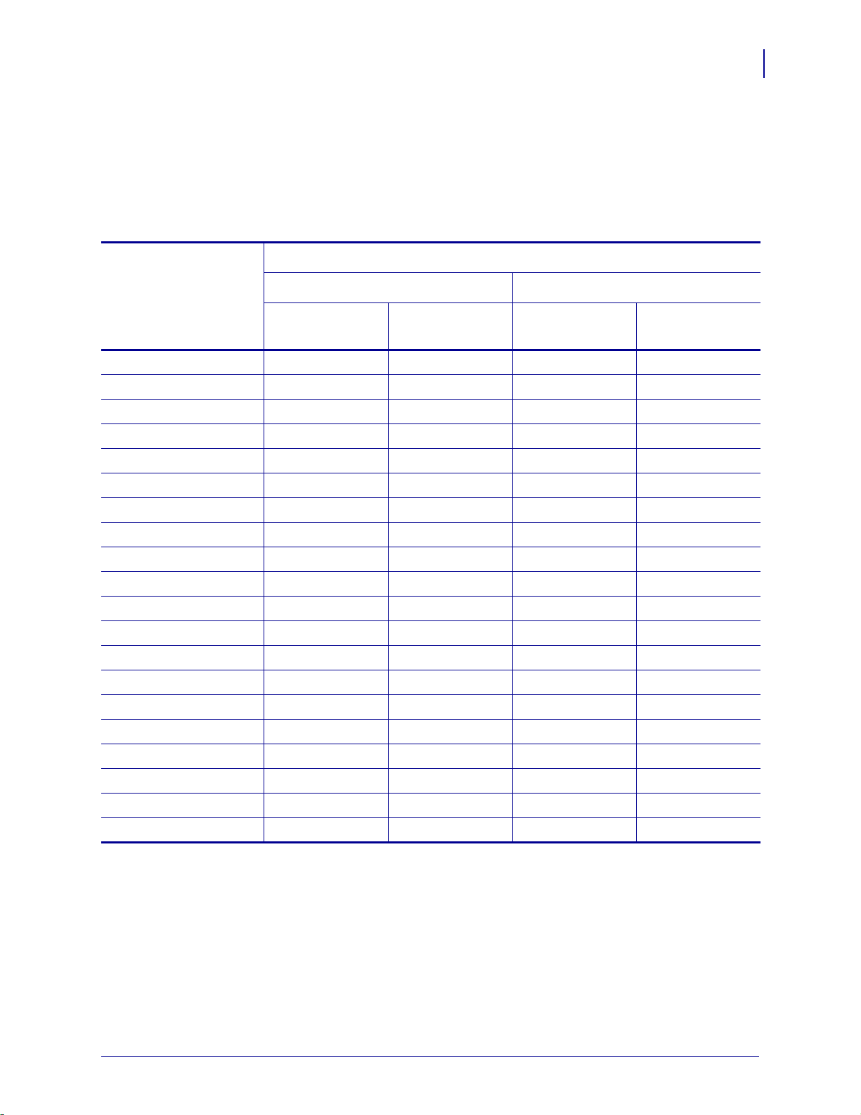
Table 1 lists the security types that are supported by the Wireless Plus Print Server. Support
varies by the card manufacturer and the card type. Select a wireless radio card that is supported
by your wireless print server and that supports the security type being used on your WLAN.
Table 1 • Security Types Supported on the Wireless Plus Print Server
Card Manufacturer
Introduction
Support
11
Security Type
Cisco CB21 Cisco 350
Cisco Symbol
LA-4121
(PCMCIA)
Compact Flash
LA-4137
Open Yes Yes Yes Yes
EAP-FAST Yes Not Supported Yes Yes
EAP-TLS Yes Not Supported Not Supported Yes
EAP-TTLS Yes Not Supported Not Supported Yes
Kerberos Not Supported Not Supported Yes Yes
LEAP Yes Yes Yes Yes
PEAP Yes Not Supported Yes Yes
WEP (40 bit and 128 bit) Yes Yes Yes Yes
WPA - LEAP Yes Yes Yes Yes
WPA - PSK Yes Yes Yes Yes
WPA- EAP-FAST Yes Yes Yes Yes
WPA- EAP-TLS Yes Yes Yes Yes
WPA- EAP-TTLS Yes Yes Yes Yes
WPA- PEAP Yes Yes Yes Yes
WPA2 - LEAP Yes Not Supported Not Supported Not Supported
WPA2 - PSK* Yes* Not Supported Not Supported Not Supported
WPA2- EAP-FAST Yes Not Supported Not Supported Not Supported
WPA2- EAP-TLS Yes Not Supported Not Supported Not Supported
WPA2- EAP-TTLS Yes Not Supported Not Supported Not Supported
WPA2- PEAP Yes Not Supported Not Supported Not Supported
* Key rotation for WPA2 PSK is supported in firmware version V60.15.8Z or later, V53.15.8Z or later., and RX.15.8Z or later.
10/12/17 P1043301-006
Page 12

12
Introduction
Support
Internal Wireless Plus Print Server and Other a/b/g/n/ac Print Servers
Table 2 lists the security types that are supported by the Internal Wireless Plus Print Server and
other print servers that include a/b/g/n/ac.
Table 2 • Security Types Supported on the
Internal Wireless Plus Print Server and all a/b/g/n/ac Print Servers
Security Type Supported?
Open Yes
EAP-FAST Yes
EAP-PEAPv2 Yes *
EAP-TLS Yes
EAP-TTLS Yes
Kerberos Not Supported
Key Management Yes *
LEAP Yes
MIC Yes *
PEAP Yes
WEP (40 bit and 128 bit) Yes
WPA - LEAP Yes
WPA - PSK Yes
WPA - EAP-FAST Yes
WPA - EAP-TLS Yes
WPA - EAP-TTLS Yes
WPA - PEAP Yes
WPA - TKIP Yes *
WPA2 - 802.1x + AES Yes *
WPA2 - LEAP Yes
WPA2 - PSK Yes
WPA2 - EAP-FAST Yes
WPA2 - EAP-TLS Yes
WPA2 - EAP-TTLS Yes
WPA2 - PEAP Yes
*Note: Supported on the n Print Server only
P1043301-006 10/12/17
Page 13

Wireless Print Server
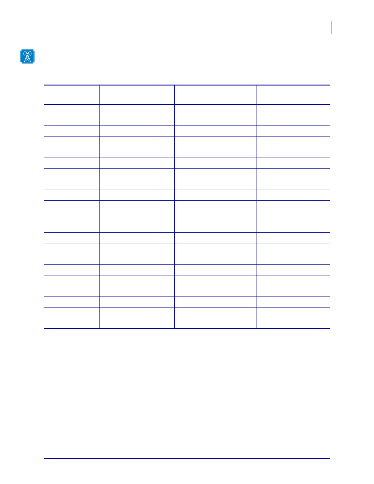
Table 3 lists the security types that are supported by the Wireless Print Server. Support varies
by the card manufacturer and the card type. Select a wireless radio card that is supported by
your wireless print server and that supports the security type being used on your WLAN. The
Wireless Print Server does not support the Cisco CB21 radio card.
Table 3 • Security Types Supported on the Wireless Print Server
Card Manufacturer
Introduction
Support
13
Security Type
Cisco Symbol
Cisco 350
LA-4121
(PCMCIA)
LA-4137
Compact Flash
Open Yes Yes Yes
EAP-FAST Not Supported Not Supported Yes
EAP-TLS Not Supported Not Supported Yes
EAP-TTLS Not Supported Yes Yes
Kerberos Not Supported Yes Yes
LEAP Yes Yes Yes
PEAP Not Supported Yes Yes
WEP (40 bit and 128 bit) Yes Yes Yes
WPA - LEAP Yes Yes Yes
WPA - PSK Yes Yes Yes
WPA- EAP-FAST Yes Yes Yes
WPA- EAP-TLS Yes Yes Yes
WPA- EAP-TTLS Yes Yes Yes
WPA- PEAP Yes Yes Yes
10/12/17 P1043301-006
Page 14

Introduction
14
Printer Requirements
Printer Requirements
Hardware—Wired Print Servers
Table 4 indicates which printers are compatible with wired print server options.
Table 4 • Wired Print Servers Available by Printer
Printers External *
Internal
Field Upgrade
Internal
Factory
105SL XXX
105SLPlus XXX
GK420 X — X
GX420/GX430 X — X
HC100 — — X
LP/TLP 2824 Plus — — X
PAX4 seriesXXX
R110PAX4 XXX
R110Xi4 XXX
RZ400 XXX
RZ600 XXX
Xi4 XXX
ZD400 Series — — X
ZD500R X X
ZE500 XXX
ZM400 XXX
ZM600 XXX
ZT200 Series X X X
ZT400 Series X — X
ZT510 X — X
ZT600 Series X — X
* For additional information on print server firmware versions, see Firmware—10/100 Print Server on
page 17.
P1043301-006 10/12/17
Page 15
Hardware—Wireless Print Servers
Table 5 indicates which printers are compatible with wireless print server options.
Table 5 • Wireless Print Servers Available by Printer
Introduction
Printer Requirements
15
Printers a/b/g/n/ac a/b/g/n b/g
Internal
Wireless Plus
Wireless
Plus
Wireless
105SL —— — X XX
105SLPlus —— X — ——
GK420 — — X — — —
GX420/430 — — X — — —
HC100 — — X — — —
LP/TLP 2824 Plus — — — — — —
PAX4 series — — X X X X
R110PAX4———XXX
R110Xi4 — — X X X X
RZ400 — — X X X X
RZ600 — — X X X X
Xi4 — — X X X
ZD400 Series X — — — — —
ZD500R — X — — — —
ZE500 — — X — — —
ZM400 — — X X X —
ZM600 — — X X X —
ZT200 Series — X — — — —
ZT400 Series — X — — — —
ZT510 X — — — — —
ZT600 Series X — — — — —
10/12/17 P1043301-006
Page 16
Introduction
16
Printer Requirements
Memory Requirements
PCMCIA and Compact Flash Memory Cards PCMCIA memory or Compact Flash
memory cards will not work and are not supported on the Wireless Plus Print Server. The
Internal Wireless Plus Print Server and the a/b/g/n/ac Print Servers do not include a slot for
these card types.
Wireless Card Socket Option The wireless print server options replace the Wireless Card
Socket Option (WCSO) in 105SL printers with a serial number of 6400357 or greater. Do not
install a wireless option board on a 105SL printer with a serial number that is less than
6400357.
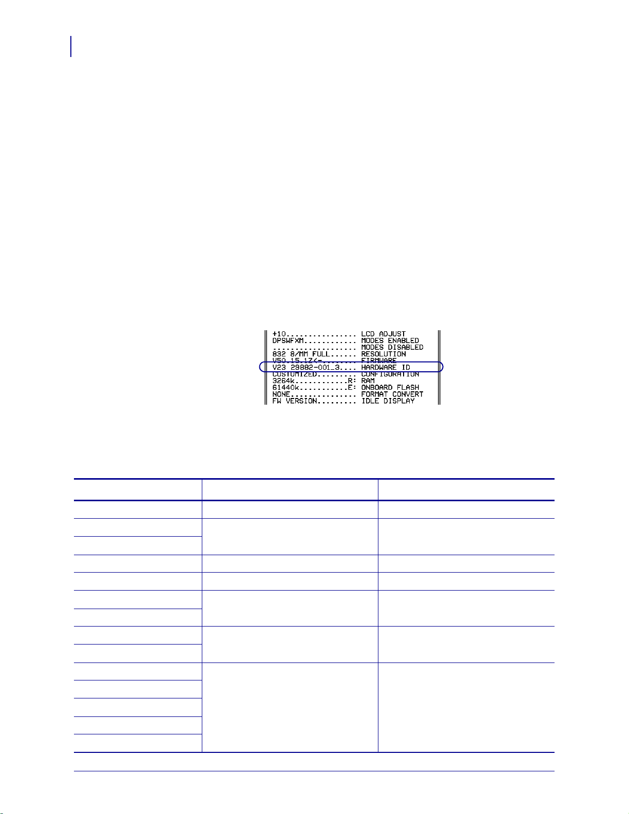
Wireless Option Board A special wireless option board must be installed in your
printer/print engine. To determine if you have a wireless option board installed, use a printer
configuration label (refer to the printing instructions in your printer User Guide). To purchase
a wireless option, contact your authorized Zebra reseller for more information.
The wireless option boards are identified by the HARDWARE ID line on the printer
configuration label.
The part numbers shown on the HARDWARE ID line indicate the wireless print se rvers as
shown in Table 6.
Table 6 • Zebra Part Numbers for Wireless Print Server Boards
Part Number Corresponds to the Following Radio Included?
P1033782-0xx n Print Server Yes
P1033557-0xx b/g Print Server Yes
P1033605-001
PCBA P1033782-03x a/b/g/n Print Server Yes
PCBA P1077918-01x a/b/g/n/ac Print Server Yes
29652-0xx Internal Wireless Plus Print Server Yes
29883-001
29651-0xx Wireless Plus Print Server No. Requires a third-party radio card.
29882-001
29881-009 Wireless Print Server No. Requires a third-party radio card.
79077
79078
79079
79100
P1043301-006 10/12/17
Page 17
Firmware—10/100 Print Server
EN: ZZ:ZZ:ZZ:ZZ:ZZ:ZZ
UID #
SN YYYYYYY
PN XXXXX
FOR HOME, OFFICE,
COMMERCIAL, OR
INDUSTRIAL USE
Tested to Comply
With FCC Standards
This Class B digital apparatus
complies with Canadian ICES-003
V2
1
All external print servers are available with several versions of print server firmware. PAX4
and 105SL printers use print server firmware version 1.01.x.
To determine the proper firmware version, first determine your hardware version.
To locate your hardware version, perform the following:
1. Which type of printer and print server do you have?
If you have… Then…
Introduction
Printer Requirements
17
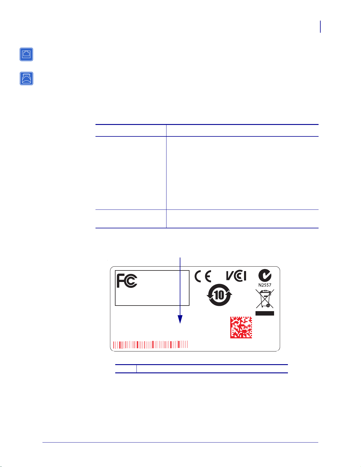
A printer with an external
print server
a. Look at the side of the print server.
b. See Figure 1. Your hardware version is listed on the
Compliance label.
c. Your hardware version number is either blank or V2.
• If your hardware version is blank, assume this
means V1 (version 1). You will need firmware
version 1.01.x.
• If your hardware version is V2, you will need
firmware version 2.01.x.
A printer with an internal
print server
a. Your hardware version will be V1.
b. You will need firmwa re versio n 1.0 1. x.
Figure 1 • External 10/100 Print Server Sample Compliance Label
10/12/17 P1043301-006
Location of hardware version
1
Page 18

Introduction
18
Printer Requirements
Firmware—Wireless
After a wireless option board is installed, your printer must be running a supported firmware
version to access the features in this manual. Table 7 shows the minimum firmware version
required.
You may download the latest firmware appropriate for your printer to access the latest
encryption features. Go to http://www.zebra.com/firmware for firmware download options.
Table 7 • Supported Firmware Versions
Printer a/b/g/n/ac Internal a/b/g/n Internal b/g
105SL — — — V60.16.X V60.15.X V60.15.X
105SLPlus — — V53.17.16Z — — —
HC100 — — — V54.16.X — —
110PAX 4
170PAX 4
R110PAX 4 — — — R62.16.X
R110Xi4 — — V53.17.11Z V.53.17.7 V.53.17.7 —
RZ400
RZ600
Xi4 — — V53.17.11Z V53.17.X V53.17.X —
ZD400
Series
ZD500 — V74.19.6Z — — — —
ZM400
ZM600
ZE500 — — V53.17.15Z — — —
ZT200
Series
ZT400
Series
ZT510 V80.20.4Z — — — — —
ZT600
Series
— — V60.17.11Z V60.16.X V60.15.X V60.15.X
— — V53.17.11Z R53.16.X R53.16.X R53.16.X
P77.19.14Z — — — — —
— — V53.17.11Z V53.16.X V53.15.X —
— V72.18.X — — — —
— V75.19.7Z — — — —
V80.20.4Z — — — — —
Internal
Wireless Plus
R63.16.X
Wireless Plus Wireless
R62.15.X
R63.15.X
R62.15.X
R63.15.X
P1043301-006 10/12/17
Page 19

Compatibility
This section identifies the various components that are compatible with all print servers.
Introduction
Compatibility
19
Software IBM
®
: Tivoli® v7.1.3, HP®: Web JetAdmin™ v7.0, OpenView™ v6.4, and any
SNMP management application via Zebra Management Information Base (MIB) all work with
both the wired and wireless print serv ers.
Specifications
External 10/100 Print Server Specifications
General Specifications
Network Connection Ethernet 10BASE-T and 100BASE-T UTP RJ-45
connection Half and Full Duplex Communications
Printer Connection Bi-directional, IEEE-1284 Centronics parallel port
(Compatibility, Nibble, and ECP)
User Interface LED activity indicators:
• bi-color display of operational status
• bi-color display of speed and network activity
Height (external dimensions) 1.2 in. 30.48 mm
Width (external dimensions) 2.8 in. 71.12 mm
Length (external dimensions) 3.2 in. 81.28 mm
Weight 2.7 oz 77 g
Electrical Maximum 450mA at 5.25VDC Power provided by
the printer (Centronics pin 18, 5VDC at 450mA)
Temperature Operating 32° to 104°F 0° to 40°C
Storage –40° to 140°F –40° to 60°C
Relative Humidity Operating 20% to 85%, non-condensing
Storage 5% to 85%, non-condensing
Agency Approvals Agency Approvals
• IEC 60950
• EN 55032, class B
• EN 55024
Agency Marks
• FCC - B
• ICES-003
• VCCI
• RCM
10/12/17 P1043301-006
Page 20
20
Introduction
Specifications
Internal Print Server Specifications
General Specifications
Network Connection Ethernet 10BaseT and 100BaseT UTP RJ-45
connection Half and Full Duplex Communications
User Interface A single (two element) LED activity indicator:
• bi-color display of operational status (solid
green or solid amber)
• bi-color display of speed and network activity
(flashing green or flashing amber)
Temperature Operating 32° to 140°F 0° to 60°C
Storage –40° to 140°F –40° to 60°C
Relative Humidity Operating 20% to 80%, non-condensing
Storage 5% to 85%, non-condensing
P1043301-006 10/12/17
Page 21
Wireless Print Server Specifications
General Specifications
Network Connection • IEEE 802.11b/g, 802.11a/b/g/n,
• Data Rates up to 300 Mb per second
• Wireless Medium DSSS and OFDM
• Frequency Band: 2.4G or 2.4G/5G
802.11a/b/g/n/ac
Introduction
Specifications
21
User Interface
• Link Status Indicator—real-time display of
network status
• Wireless Signal Indicators
Electrical Power provided by the printer
Temperature Operating 32° to 140°F 0° to 60°C
Storage –40° to 140°F –40° to 60°C
Relative Humidity Operating 20% to 80%, non-condensing
Storage 5% to 85%, non-condensing
10/12/17 P1043301-006
Page 22

Introduction
Notes • ___________________________________________________________________
__________________________________________________________________________
__________________________________________________________________________
__________________________________________________________________________
__________________________________________________________________________
__________________________________________________________________________
__________________________________________________________________________
__________________________________________________________________________
__________________________________________________________________________
__________________________________________________________________________
22
Specifications
P1043301-006 10/12/17
Page 23

2
Installation
This chapter provides information on how to install the Zebra’s wired and wireless print
servers.
Contents
External 10/100 Print Server . . . . . . . . . . . . . . . . . . . . . . . . . . . . . . . . . . . . . . . . . . . . . . 24
Before You Begin . . . . . . . . . . . . . . . . . . . . . . . . . . . . . . . . . . . . . . . . . . . . . . . . . . . . . 24
Illustration. . . . . . . . . . . . . . . . . . . . . . . . . . . . . . . . . . . . . . . . . . . . . . . . . . . . . . . . . . . 25
Installation Instructions . . . . . . . . . . . . . . . . . . . . . . . . . . . . . . . . . . . . . . . . . . . . . . . . 26
Internal 10/100 Print Server. . . . . . . . . . . . . . . . . . . . . . . . . . . . . . . . . . . . . . . . . . . . . . . 27
Wireless Print Servers . . . . . . . . . . . . . . . . . . . . . . . . . . . . . . . . . . . . . . . . . . . . . . . . . . . 27
Install a Radio Card in a Wireless Print Server . . . . . . . . . . . . . . . . . . . . . . . . . . . . . . . . 27
Wireless Radio Card . . . . . . . . . . . . . . . . . . . . . . . . . . . . . . . . . . . . . . . . . . . . . . . . . . 27
Compact Flash Wireless Radio Card. . . . . . . . . . . . . . . . . . . . . . . . . . . . . . . . . . . . . . 29
10/12/17 P1043301-006
Page 24
Installation
24
External 10/100 Print Server
External 10/100 Print Server
This section provides you with an illustration of the externa l 10/100 Print Server and t he step s
required for its installation. For a list of compatible printers, see Hardware—Wired Print
Servers on page 14.
Before You Begin
Important • In order to take advantage of all features described in this manual, you must
download firmware X.14 or later.
Note • Not all printers support firmware X.14 or later. On those printers, the features
for this print server will be limited.
To upgrade you printer firmware, complete these steps:
1. If your printer has firmware x.12 firmware, you must upgrade your printer firmware to
version x.14.x or higher.
2. To upgrade your firmware, visit the Zebra Web site, and down load th e lat est firmw are fo r
your printer:
www.zebra.com/firmware
3. Confirm that the upgrade was successful:
If... Then...
Your printer has an LCD Look at the lower right-hand corner and confirm the
version of firmware that is on your printer.
Your printer does not have
an LCD
Print out a configuration label to see the version of
firmware that is on your printer.
P1043301-006 10/12/17
Page 25
Illustration
1
5
4
3
2
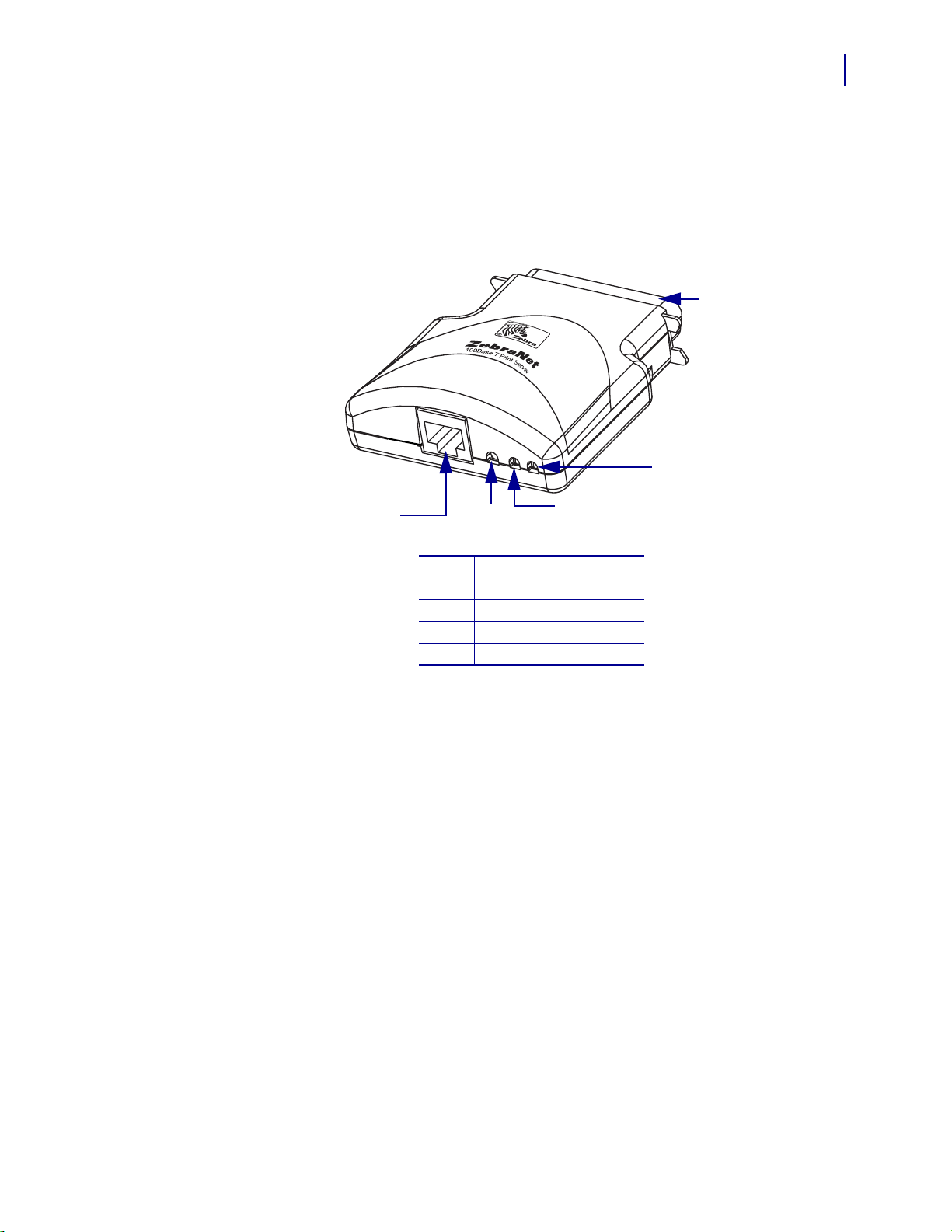
Figure 2 shows an external 10/100 Print Server. When necessary, refer back to this illustration
during the installation steps.
External 10/100 Print Server
Figure 2 • External 10/100 Print Server
Installation
25
Parallel connector
1
Network status LED
2
Status LED
3
Test button
4
Ethernet connector
5
For more details on status indicators, see External 10/100 Print Server Network Status and
Status Indicators on page 120.
10/12/17 P1043301-006
Page 26

Installation
Parallel
Port
Connector
Printer Back
26
External 10/100 Print Server
Installation Instructions
To install an external 10/100 Print Server, complete these steps:
1. Turn off (O) the printer.
2. On the back of the printer, connect the external 10/100 Print Server device to the parallel
port.
3. Secure the wire locks.
4. On the back of the external 10/100 Print Server, connect an active Ethernet cable to the
RJ-45 connector Ethernet conne ctor.
5. Turn on (I) the printer.
The external 10/100 Print Server performs a Power On Self-Test (POST). This takes about
45 seconds. During the POST, the external 10/100 Print Server Status LED (just below the
TEST button) turns red and flashes on and off. Once the POST is successfully completed
and the external 10/100 Print Server is fully initialized, the Status LED tu rns green.
For more details on status indicators, see External 10/100 Print Server Network Status and
Status Indicators on page 120.
Note • If there is not an active Ethernet cable attached to the external 10/100 Print Server,
the Status LED turns red and slowly flashes on and off.
6. To check the status of the external 10/100 Print Server, press the Test button located on the
back of the external 10/100 Print Server.
This prints out a configuration label of the external 10/100 Print Server. To see a sample
label, see Figure 4 on page 35.
P1043301-006 10/12/17
Page 27

Internal 10/100 Print Server
To install an internal 10/100 print server, see the installation instructions that came with the
print server.
Wireless Print Servers
To install a wireless print server, see the installation instructions that came with the print
server.
Install a Radio Card in a Wireless Print Server
Note • This section applies only to the Wireless Print Server and the Wireless Plu s Print
Server. All other wireless print servers covered by this manual have a built-in radio.
Printers that have the wireless option board installed can use any of th e wireless rad io cards or
Compact Flash wireless radio cards listed in Supported Wireless Radio Cards on page 9. This
section provides instructions for installing either type of card. Most printers use a clear plastic
RF cover over the wireless radio card or compact Flash wireless radio card.
Installation
Internal 10/100 Print Server
27
Wireless Radio Card
This section applies to PCMCIA or CardBus wireless radio cards.
Note • Z4Mplus, R4Mplus, and Z6Mplus printers do not support CardBus wireless radio
cards.
To install a wireless radio card, complete these steps:
1. Turn off (O) the printer.
2. Remove and discard the metal cover that was shipped in place over the wireless option
card slot on the back of the printer.
10/12/17 P1043301-006
Page 28
Installation
4
2
1
3
3
1
2
28
Install a Radio Card in a Wireless Print Server
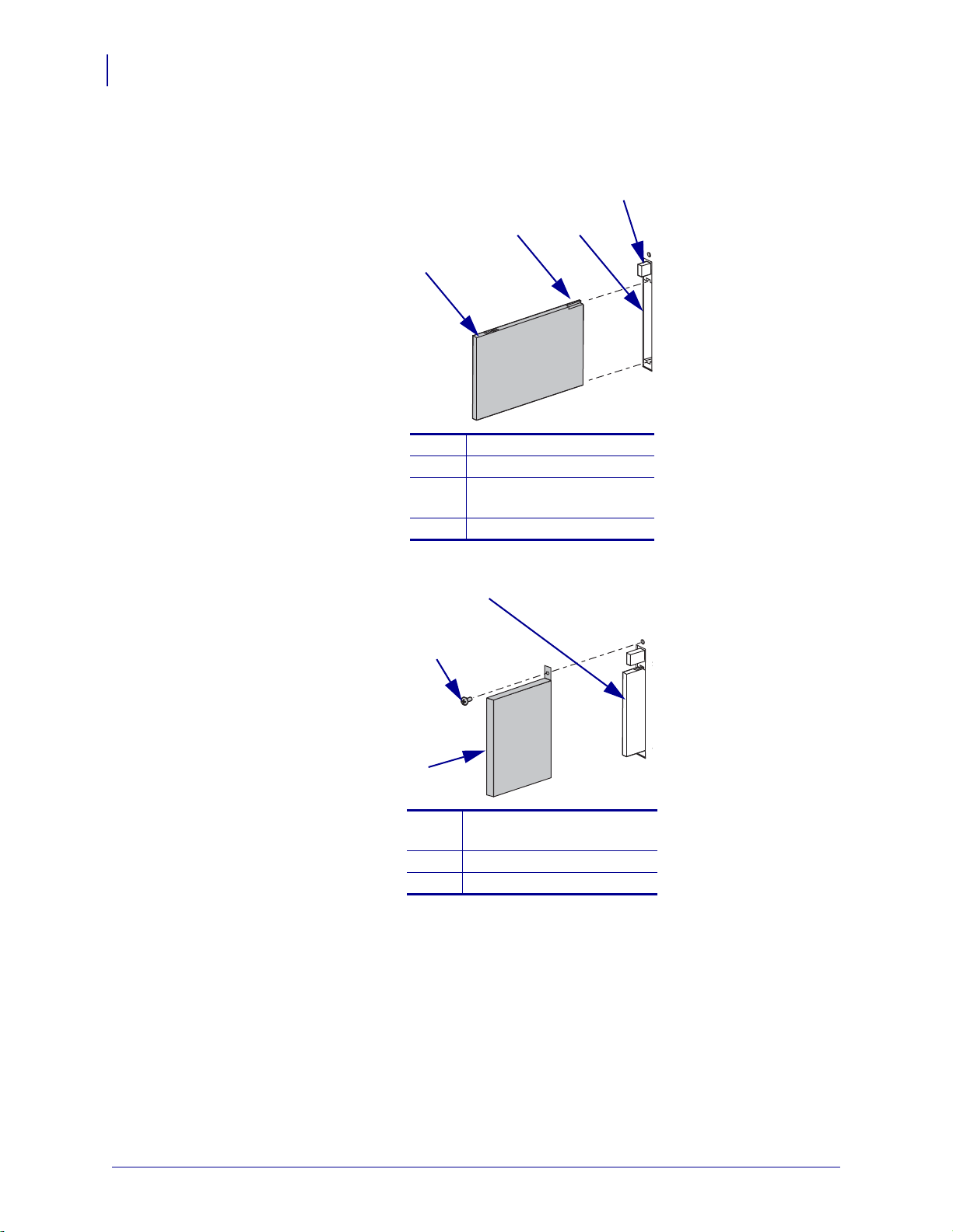
3. Position the notch on the wireless radio card on the top, leading edge. Insert the wireless
radio card into the wireless option card slot on the back of the printer until the card-eject
button pops out.
Wireless radio card
1
Notch
2
Wireless option card slot
3
on back of printer
Card-eject button
4
4. Place the RF card cover over the wireless radio card, and secure it with a small screw.
Clear plastic RF card cover
1
(not used on all printers)
Screw
2
Wireless radio card
3
5. Turn on (I) the printer.
The printer restarts and uses the wireless radio card to communicate with your WLAN.
Allow several minutes for the printer to connect to the network. For more information
about wireless status, refer to View Wireless Status through the Control Panel on page 41
or Troubleshooting the Wireless Print Server on page 125.
P1043301-006 10/12/17
Page 29
Compact Flash Wireless Radio Card
4
2
1
3
This section applies to Compact Flash wireless radio cards, which require an adapter before
they can be used in the wireless option card slot.
To install a Compact Flash wireless radio card and adapter, complete these
steps:
1. If you have not already done so, turn off (O) the printer.
2. Remove and discard the metal cover that was shipped in place over the wireless option
slot on the back of the printer.
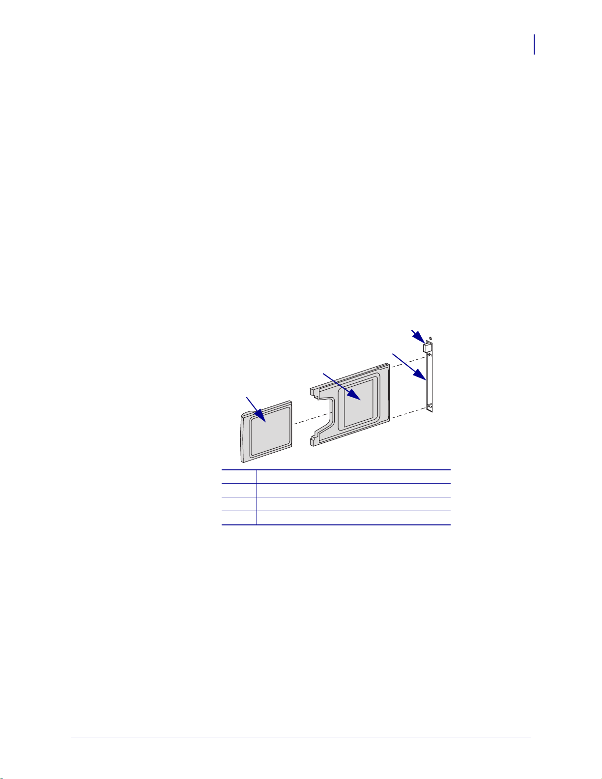
3. See Figure 3. Position the adapter with the back facing as shown. Insert the adapter into
the wireless option card slot on the back of the printer until the card-eject button pops out.
4. See Figure 3. Insert the Compact Flash wireless radio card into the adapter.
Figure 3 • Installing a Compact Flash Wireless Radio Card
Installation
Install a Radio Card in a Wireless Print Server
29
Back of Compact Flash wireless radio card
1
Back of adapter
2
Wireless option card slot on back of printer
3
Card-eject button
4
10/12/17 P1043301-006
Page 30
Installation
3
1
2
30
Install a Radio Card in a Wireless Print Server
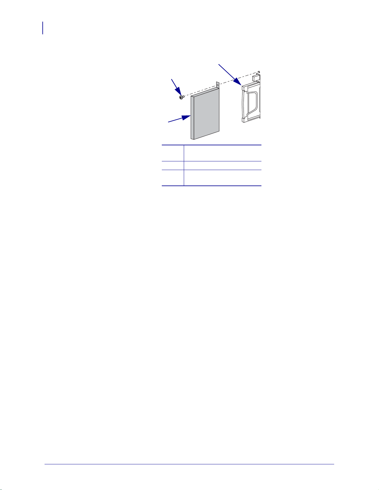
5. Place the RF card cover over the wireless radio card, and secure it with a small screw.
6. Turn on (I) the printer.
The printer restarts and uses the wireless radio card to communicate with your WLAN.
Allow several minutes for the printer to connect to the network. For more information
about wireless status, refer to View Wireless Status through the Control Panel on page 41
or Troubleshooting the Wireless Print Server on page 125.
Clear plastic RF card cover
1
(not used on all printers)
Screw
2
Compact Flash wireless
3
radio card and adapter
P1043301-006 10/12/17
Page 31

Getting Started
This chapter provides you with information and procedures for working with the most
frequently used print server features.
3
Contents
Before You Begin . . . . . . . . . . . . . . . . . . . . . . . . . . . . . . . . . . . . . . . . . . . . . . . . . . . . . . . 33
Default User ID and Password. . . . . . . . . . . . . . . . . . . . . . . . . . . . . . . . . . . . . . . . . . . 33
Printing a Configuration Label— External 10/100 Print Server . . . . . . . . . . . . . . . . . . . . 34
Printing a Network Configuration Label . . . . . . . . . . . . . . . . . . . . . . . . . . . . . . . . . . . . . . 36
Configuration of Wireless Securities . . . . . . . . . . . . . . . . . . . . . . . . . . . . . . . . . . . . . . . . 40
View Wireless Status through the Control Panel . . . . . . . . . . . . . . . . . . . . . . . . . . . . . . . 41
LCD Link Status and Wireless Signal Indicators (Other Printers) . . . . . . . . . . . . . . . . 42
HC100 Wireless Status Indicator Lights . . . . . . . . . . . . . . . . . . . . . . . . . . . . . . . . . . . 43
Network Status Indicator Lights. . . . . . . . . . . . . . . . . . . . . . . . . . . . . . . . . . . . . . . . . . 44
Determining the Active Print Server. . . . . . . . . . . . . . . . . . . . . . . . . . . . . . . . . . . . . . . . . 45
Viewing IP Addresses and the Active Print Server. . . . . . . . . . . . . . . . . . . . . . . . . . . . 45
Active Device Selection . . . . . . . . . . . . . . . . . . . . . . . . . . . . . . . . . . . . . . . . . . . . . . . . 46
Assigning an IP Address on any Print Server . . . . . . . . . . . . . . . . . . . . . . . . . . . . . . . . . 48
With Dynamic Host Configuration Protocol (DHCP) . . . . . . . . . . . . . . . . . . . . . . . . . . 48
Assigning an IP Address Without DHCP via ZebraNet Bridge. . . . . . . . . . . . . . . . . . . 48
Assigning an IP address Without DHCP from the Control Panel. . . . . . . . . . . . . . . . . 48
Assigning an IP Address Without DHCP via a Telnet Session. . . . . . . . . . . . . . . . . . . 49
Setting and Monitoring Alerts on Any Print Server . . . . . . . . . . . . . . . . . . . . . . . . . . . . . . 51
ZebraLink Alerts. . . . . . . . . . . . . . . . . . . . . . . . . . . . . . . . . . . . . . . . . . . . . . . . . . . . . . 51
Using ZebraNet Bridge . . . . . . . . . . . . . . . . . . . . . . . . . . . . . . . . . . . . . . . . . . . . . . . . 51
Using WebView . . . . . . . . . . . . . . . . . . . . . . . . . . . . . . . . . . . . . . . . . . . . . . . . . . . . . . 53
10/12/17 P1043301-006
Page 32

Getting Started
32
Checking Print Server Configuration Settings . . . . . . . . . . . . . . . . . . . . . . . . . . . . . . . . . 56
Using ZebraNet Bridge . . . . . . . . . . . . . . . . . . . . . . . . . . . . . . . . . . . . . . . . . . . . . . . . 56
Using WebView . . . . . . . . . . . . . . . . . . . . . . . . . . . . . . . . . . . . . . . . . . . . . . . . . . . . . . 56
Enabling Protocols. . . . . . . . . . . . . . . . . . . . . . . . . . . . . . . . . . . . . . . . . . . . . . . . . . . . . . 59
Using WebView . . . . . . . . . . . . . . . . . . . . . . . . . . . . . . . . . . . . . . . . . . . . . . . . . . . . . . 59
Defaulting ALL Print Servers . . . . . . . . . . . . . . . . . . . . . . . . . . . . . . . . . . . . . . . . . . . . . . 61
Using WebView . . . . . . . . . . . . . . . . . . . . . . . . . . . . . . . . . . . . . . . . . . . . . . . . . . . . . . 61
Using ZebraNet Bridge . . . . . . . . . . . . . . . . . . . . . . . . . . . . . . . . . . . . . . . . . . . . . . . . 63
Defaulting a 10/100 Print Server . . . . . . . . . . . . . . . . . . . . . . . . . . . . . . . . . . . . . . . . . 63
Defaulting the Print Servers on the ZM400 and ZM600 Printers. . . . . . . . . . . . . . . . . 64
Defaulting the Print Servers on the LP/TLP 2824 Plus and G-Series Printers. . . . . . . 64
Defaulting the Print Servers on the HC100 Printers . . . . . . . . . . . . . . . . . . . . . . . . . . 64
Defaulting the Print Servers on 105SL, PAX4, Xi4, ZE500, and 105SLPlus Printers . 65
Defaulting the Print Servers on the ZD400, ZD500R, and ZTxxx Printers. . . . . . . . . . 65
P1043301-006 10/12/17
Page 33

Before You Begin
Zebra’s wired and wireless print servers offers many features, but how you access and work
with them is dependent on your environment.
Default User ID and Password
Throughout the procedures in this document, there are some features that require the default
User ID and/or default password. If you are prompted, these are the defaults:
• User ID: admin
• Password: 1234
Getting Started
Before You Begin
33
10/12/17 P1043301-006
Page 34

Getting Started
34
Printing a Configuration Label— External 10/100 Print Server
Printing a Configuration Label—
External 10/100 Print Server
To print the external 10/100 Print Server configuration label, the printer must be load ed with a
label that is wide enough for the image (Table 8).
Table 8 • Minimum Label Width
DPI Inches mm
600 1.63 41.28
300 1.63 41.28
211 2.5 63.5
150 5.0 127.00
To print an external 10/100 Print Server configuration label, complete these steps:
1. Turn on (I) the printer and let it complete its power-up cycle.
2. When the POST cycle is complete, press the Test button and hold it in for a few seconds
before you release it.
An external 10/100 Print Server configuration label prints. You r configu ration la bel looks
similar to Figure 4 on page 35.
P1043301-006 10/12/17
Page 35

Getting Started
Printing a Configuration Label— External 10/100 Print Server
Figure 4 • Configuration Label for an External 10/100 Print Server
35
3. From the configuration label, you need to look for these numbers:
• ADDRESS (IP address)
• SUBNET MASK
• DEFAULT GATEWAY
• SERIAL NUMBER
• HARDWARE ADDRESS (MAC address)
4. On the configuration label that prints out for your external 10/100 Print Server device,
circle the aforementioned settings. You can now proceed to Assigning an IP Address on
any Print Server on page 48.
10/12/17 P1043301-006
Page 36

Getting Started
36
Printing a Network Configuration Label
Printing a Network Configuration Label
Table 9 shows the minimum label widths needed to print a network configuration label with
different DPI printheads.
Table 9 • Minimum Label Width
DPI Inches MM
600 1.25 31.75
300 2.50 63.50
200 3.69 93.73
To print the network settings for your printer, complete these steps:
1. Which printer do you have?
If you have a… Then…
ZTxxx or ZD500R Use the PRINT INFORMATION > NETWORK option to print a
network configuration label (Figure 5 on page 38 ). You can access this
menu item from the TOOLS menu or the NETWORK menu. Refer to the
User Guide for your printer for specific instructions on how to use the
control panel.
ZM400 or ZM600
a. Press SETUP/EXIT to enter the Setu p Mode.
b. Scroll through the parameters by pressing PLUS (+) until you reach
LIST NETWORK.
c. Press SELECT.
d. Press PLUS (+) to print a network configuration label (Figure 5
on page 38).
e. Press SETUP/EXIT twice to exit the Setup Mode.
G-Series or
LP/TLP 2824 Plus
a. Turn on (I) the printer and let it complete its power-up cycle.
b. Press and hold FEED until you see one flash of the LED.
c. After the LED flashes, release the button. Printer and a network
configuration labels (Figure 6 on page 39) print.
ZD400 Series
a. Turn on (I) the printer and let it complete its power-up cycle.
b. Press and hold FEED and CANCEL for 2 seconds.
c. After 2 seconds, release the buttons. Printer and a network
configuration labels (Figure 6 on page 39) print.
HC100
Note • The HC100 does not have a network configuration label.
However, the IP Address, MAC Address, and other useful
information appear on the printer configuration wristband.
a. Turn on (I) the printer and let it complete its power-up cycle.
b. Press and hold PAUSE/FEED until the green lights turn off on the
printer status indicator and the orange lights blink once.
c. Release PAUSE/FEED to print a printer configuration wristband
(Figure 7 on page 39).
P1043301-006 10/12/17
Page 37

If you have a… Then…
Getting Started
Printing a Network Configuration Label
37
Xi4, PAX4, 105SL, ZE500, or
105SLPlus
2. From the configuration label, look for these numbers:
• IP PROTOCOL *
• IP ADDRESS
•SUBNET MASK *
• DEFAULT GATEWAY *
• MAC ADDRESS
* Not available on HC100
3. On the network configuration label, circle the aforementioned settings. You can now
proceed to Assigning an IP Address on any Print Server on page 48.
a. Press SETUP/EXIT to enter the Setu p Mode.
b. Scroll through the parameters by pressing NEXT/SAVE
(
) until you reach LIST NETWORK.
c. Press PLUS (+) to print a network configuration label (Figure 5
on page 38).
d. Press SETUP/EXIT to exit the Setup Mode.
e. Press NEXT/SAVE to permanently save your changes.
10/12/17 P1043301-006
Page 38

Getting Started
38
Printing a Network Configuration Label
Only the sections applicable to your printer are printed on the network configuration label.
Figure 5 • Sample Network Configuration Labels
P1043301-006 10/12/17
Page 39

Getting Started
Printing a Network Configuration Label
Figure 6 • Sample Network Configuration Label for G-Series
or LP/TLP 2824 Plus Printers
Figure 7 • Sample Printer Configuration Wristband for HC100
39
The IP ADDRESS and MAC ADDRESS fields will have values only if a wired or w ireless
print server is active.
10/12/17 P1043301-006
Page 40

Getting Started
40
Configuration of Wireless Securities
Configuration of Wireless Securities
Important • A wireless option board must be installed on your printer before you can
configure the printer to communicate using a wireless radio card. See Hardware—Wireless
Print Servers on page 15 to determine if your printer has a wireless board. See Firmware—
Wireless on page 18 for the required firmware version.
You may configure your printer for wireless operati on in the following ways:
Through the Network Setup Wizard. The Network Setup Wizard is part of the ZebraNet
Bridge Enterprise utility. The Network Setup Wizard writes a scrip t for you. On the last screen
of the wizard, you may choose to send the script directl y to your printer, or yo u may choo se to
save the script to a file. The saved file has several purposes:
• The file can be sent to the printer through any available connection (serial, parallel, USB,
or wired print server).
• The file can be resent to the printer after the network settings have been restored to factory
defaults.
• The file can be sent to multiple printers that will use the same network settings.
Note • To configure wired and wireless print servers on t he same print er, run the prog ram
once for each print server, creating a script for the wired print server and another for the
wireless print server.
The ZebraNet Bridge Enterprise utility resides on the User CD for your printer an d is available
through http://www.zebra.com/software. ZebraNet Bridge Enterprise version 1.2.5 or later is
required to configure the printer correctly for use.
Through ZPL script that you write. Use the ^WX command to set the basic parameters
for security type. You can send the command through any available connection (serial,
parallel, USB, or wired print server).
Refer to the Programming Guide for ZPL, ZBI, Set-Get-Do, Mirror, and WML for more
information. A copy of the manual is available at http://www.zebra.com/manuals or on the
User CD that came with your printer.
Through Set/Get/Do (SGD) commands. Begin with wlan.security to set the
wireless security type. Depending on which security type that you select, other SGD
commands will be necessary to specify other parameters. You can send the commands through
any available connection (serial, parallel, USB, or wired print server).
Refer to the Programming Guide for ZPL, ZBI, Set-Get-Do, Mirror, and WML for more
information. A copy of the manual is available at http://www.zebra.com/manuals or on the
User CD that came with your printer.
Note • With printers running APL-I, APL-D, or EPL firmware, the only way to configure
wireless settings is through SGD commands.
P1043301-006 10/12/17
Page 41

View Wireless Status through the Control Panel
View Wireless Status through the Control Panel
After the wireless print server is configured, you may view the wireless status on the printer’s
control panel in many cases.
• Printers with an LCD display text or symbols (see LCD Link Status and Wireless Signal
Indicators (Other Printers)).
• The HC100 printer does not have an LCD, so the wireless status is indicated by the control
panel lights (see HC100 Wireless Status Indicator Lights on page 43).
• The ZT210, ZT220, ZT230 printers also use control panel lights to indicate the wireless
status (see Network Status Indicator Lights on page 44).
Note • Refer to the User Guide for your printer for specific instructions on how to use the
control panel.
LCD Link Status and Wireless Signal Indicators (ZD500)
• Link Status Indicator
The wireless link status indicator appears at the upper right of the LCD, providing a
real-time display of the printer’s network status.
Getting Started
41
Status Indicator Meaning
The wireless radio is associated with the WLAN.
The wireless radio is not associated with the WLAN. Verify that your
printer’s wireless settings match those of the WLAN.
The wireless radio is associated and authenticated to the WLAN.
blank
The printer is checking for a wired print server.
The printer is running a wired print server.
The wireless print server board is not installed or not installed correctly.
• Wireless Signal Indicators
The wireless signal indicators appears at the upper right of the LCD, providing a real-
time display of the signal strength and quality.
Wireless Signal Indicator Description
These bars indicate the relative strength of the wireless signal. The more
bars shown, the better the connection is between the printer and the
network.
If your printer indicates a signal strength but you cannot communicate with
the printer from your computer, move the printer to a different location to
try to get a better signal strength or signal quality. This situation could also
indicate that the printer is associated with, but not authenticated with, your
access point.
ZD50
10/12/17 P1043301-006
Page 42

Getting Started
42
View Wireless Status through the Control Panel
LCD Link Status and Wireless Signal Indicators (Other Printers)
This section applies to the PAX4, RPAX4, 105SL, RZ400, RZ600, ZM400, ZM600, Xi4,
R110Xi4, 105SLPlus,and ZE500 printers/print engines
Link Status Indicator The wireless link status indicator appears at the bottom left of the
LCD, providing a real-time display of the printer’s network status.
Status Indicator Meaning
cycling through characters
The wireless radio card is associated with the WLAN.
. o O
underscore
_
• The wireless radio card is not associated with the WLAN. Verify that
your printer’s wireless settings match those of the WLAN.
• The firmware on the wireless radio card may need to be updated. See
Supported Wireless Radio Cards on page 9 for the required firmware
versions.
blank
• The printer is checking for a wired print server.
• The printer is running a wired print server.
• The wireless print server board is not installed or not installed correct ly .
Wireless Signal Indicators Depending on which prin ter/p r int engine you are using, press
the following key to access and scroll through the wireless signal indicators on the LCD:
• The right oval for the PAX4 and RPAX4 print engines
PLUS (+) for the 105SL, RZ400, RZ600, ZM400, ZM600, Xi4, R110Xi4, 105SLPlus,and
•
the ZE500 printers/print engines
Wireless Signal Indicator Description
SIGNAL STRENGTH and
SIGNAL QUALITY
When these indicators display percentages, the wireless radio card is
communicating with the network. The higher the number is, the better
the connection is between the printer and the network.
If your printer indicates a signal strength but you cannot communicate
with the printer from your computer, move the printer to a different
location to try to get a better signal strength or signal quality. This
situation could also indicate that the printer is associated with, but not
authenticated with, your access point.
NOISE LEVEL This number indicates any electrical interference with the wireless
signal.
If your printer cannot communicate with the network and the noise level
is high, move the printer to a location that is free of interference.
P1043301-006 10/12/17
Page 43

HC100 Wireless Status Indicator Lights
The following table shows the wireless status indicator lights for the HC100 printer.
Getting Started
View Wireless Status through the Control Panel
43
Wireless Status
Indicator
Meaning
Steady Green The printer is associated with a wi reless network. The signal strength is strong.
Flashing Green The printer is NOT associated with a wireless network. The signal streng th i s stro ng .
Steady Orange The printer is associated with a wireless network. The signal strength is weak.
Flashing Orange The printer is NOT associated with a wireless network. The signal strength is weak.
10/12/17 P1043301-006
Page 44

Getting Started
44
View Wireless Status through the Control Panel
Network Status Indicator Lights
The following table describes the network status i ndicato r lights th at are prese nt on th e ZTxxx
printers.
Printers with a wired Ethernet option
NETWORK light off
No Ethernet link is available.
NETWORK light steady green
A 100 Base link was found.
NETWORK light steady yellow
A 10 Base link was found.
NETWORK light steady red
An Ethernet error condition exists. The printer is not
connected to your network.
Printers with a wireless option
NETWORK light off
A radio was found during power-up. The printer is
attempting to associate with the network. The light flashes
red while the printer associates with the network. The light
then flashes yellow while the printer is authenticating with
the network.
NETWORK light steady green
The radio is associated with your network and
authenticated, and the WLAN signal is strong.
NETWORK light flashing green
The radio is associated with your network and
authenticated, but the WLAN signal is weak.
NETWORK light steady red
A WLAN error condition exists. The printer is not
connected to your network.
P1043301-006 10/12/17
Page 45

Determining the Active Print Server
asterisk indicating
active print server
Most printers can have wired and wireless print servers installed at the same time. However,
only one of the installed print servers can be active at any given time.
Viewing IP Addresses and the Active Print Server
The wired and wireless print servers have different IP addresses. The printer’s control panel
displays the IP address of the active print server (see V iew Wireless Status through the Control
Panel on page 41). You can view the printer’s web pages and send label formats to the printer
through the active print server’s IP address.
The network configuration label (Figure 8) displays the IP addresses of all installed print
server devices and indicates the active print server with an asterisk (circled in Figure 8). To
print a network configuration label for wired print servers, see Printing a Network
Configuration Label on page 36 or for wireless print servers, see Configuration of Wireless
Securities on page 40.
Figure 8 • Active Print Sever on Sample Network Configuration Label
Getting Started
Determining the Active Print Server
45
10/12/17 P1043301-006
Page 46

Getting Started
46
Determining the Active Print Server
Active Device Selection
Your active print server selection is dependent on the model of printer or print engine that you
have.
If your printer is
a(n)…
• ZT210, ZT220,
ZT230
• 105SL
• R110PAX4
• PAX4
• 105SLPlus
• R110Xi4
• RZ400, RZ600
• Xi4
• ZD500R
• ZE500
• ZM400, ZM600
• ZT410, ZT420
• ZT510
• ZT610, ZT620
Then…
Only one print server (wired or wireless) can be installed at a
time. Thus, the print server installed is the primary print server.
You may select which installed device is the primary net work
device. The printer will try to use the primary network device as
the active print server before trying the other installed options.
These printers and print engines use X60.16.x or later firmware.
The default for the printer is to skip
the check for a wired print
server during boot-up. This makes the wireless print server the
primary network device if a wireless pr int server is installed. To
change this default and allo w the wired print server to be the
primary network device when it is connected, use one of th e
following methods to tell the printer to check for a wired print
server at boot-up time:
• the WIRED PS CHECK parameter on the control panel
• the ^NB ZPL command
Table 10 identifies which device becomes the active print server
under various conditions.
These printers support the simultaneous installation of an
internal, external, and a wireless print server. Even though all
three print servers may be installed, only one is connected to the
network and is the active print server.
Table 11 outlines priorities and identifies which device becomes
the active print server when multiple print servers are installed.
You may select whether the wired or wireless print server will be
the primary connection by using one of the following methods:
• the PRIMARY NETWORK parameter on the control panel
• the ^NC ZPL command
P1043301-006 10/12/17
Page 47

Determining the Active Print Server
Table 10 • Results of Check for Wired Print Server
Getting Started
47
If the Check
for Wired Print
Server is
set to:
Skip
Installed and Connected to
a Live Ethernet Network Then the Active Print
Server will be:
Wired Wireless*
XX Wireless
XWired
X Wireless
Check
XX Wired
XWired
X Wireless
* NOTE: A wireless option board must have an active radio that can properly associate to an access point.
Table 11 • Active Print Server Matrix
If the
Primary
Network is
set to:
Installed and Connected to
a Live Ethernet Network Then the Active
Print Server will be:
Internal External Wireless*
X X X Internal
Wired
XX External
X Wireless
X X X Wireless
Wireless
X X Internal
X External
* NOTE: A wireless option board must have an active radio that can properly associate to an access point.
10/12/17 P1043301-006
Page 48

Getting Started
48
Assigning an IP Address on any Print Server
Assigning an IP Address on any Print Server
Before you can begin working with a print server, you must get or assign an IP address for the
print server device.
The four different ways to assign an IP address are:
•DHCP
• ZebraNet Bridge Enterprise
• Printer Control Panel/LCD
•Telnet
Important • For specific information on the default User ID and/or default password, see
Default User ID and Password on page 33.
With Dynamic Host Configuration Protocol (DHCP)
If your network uses DHCP, your print server device is assigned a temporary IP address.
Note • Check with your Network Administrator to see whether your network uses DHCP.
Assigning an IP Address Without DHCP via ZebraNet Bridge
ZebraNet Bridge may be used to set the IP address. Refer to the ZebraNet Bridge Enterprise
User Guide for more detailed information.
Assigning an IP address Without DHCP from the Control Panel
These steps can be used with all printers with a control panel.
To assign an IP address from the control panel (or LCD), complete these steps:
Important • A 10/100 Print Server must have firmware 1.xx.x and higher and your Zebra
printer must have firmware x.10 or higher with a control panel.
1. Turn on (I) the printer and wait until the control panel says PRINTER READY.
2. See Wired Network Parameters on the Printer Display on page 114 or Wireless Network
Parameters on the Printer Display on page 116 for specific print server menu options or
your printer’s user guide for specific instructions on the operation of your printer.
3. You may edit any of the following network settings in order to communicate with any
print server in your network environment.
Important • To change any of these settings, you need to enter the printer password. The
default password is
P1043301-006 10/12/17
1234.
Page 49

Getting Started
Assigning an IP Address on any Print Server
• ip resolution (dynamic, permanent) The printer menu item IP RESOLUTION
must be set to PERMANENT if attempting to assign the IP address from the contro l
panel.
• default gateway (default setting of 000.000.000.000)
• subnet mask (default setting 255.0.0.0)
• ip address (if initial default setting is 0.0.0.0, after 2 minutes this defaults to
192.168.254.254
• ip protocol (gleaning only, RARP, BOOTP, DHCP, DHCP and BOOTP, all)
Assigning an IP Address Without DHCP via a Telnet Session
The methods used for assigning an IP address with a Telnet session are Static Route and
Gleaning.
Important • This applies to any TCP/IP capable workstation/host networked with the Zebra
printer. Both, the workstation/host and the print server, must be on the same network
segment.
49
Before you can Telnet to the print server and configure it, you must first assign the print server
a temporary IP address.
Static Route
To use this method, complete these steps:
1. Turn on (I) the printer and wait for 2 minutes to allow for the device to complete the
self-test.
During this time, the print server performs an address broadcast. If no address is assigned
to the unit (via DHCP or BootP), it uses a default address. The default address for print
server is 192.168.254.254. Print the print server configuration label to confirm the
address. For details, see Before You Begin on page 33.
2. You can use the route add command to place the default IP address into the
workstation's network routing table.
3. At the workstation/host command prompt (in Windows, at the DOS prompt), type:
route add **** "IP address of the workstation" 0
where **** is the IP address on any print server configuration label
Note • The zero (0) placed at the end of the “route add” command is optional on some
systems.
4. Telnet to the print server by typing:
"Telnet xxx.xxx.xxx.xxx"
The password is 1234.
5. At this point, you can alter the settings as desired. When complete, do a reset and allow
the print server self-test to complete before proceeding with any communications activity.
10/12/17 P1043301-006
Page 50

Getting Started
50
Assigning an IP Address on any Print Server
Gleaning
A method by which the print server uses the IP address of the first ping packet that is sent to its
hardware address.
Note • Gleaning works only on local subnets at routers. It does not pass Address Resolution
Protocol (ARP) broadcasts.
To use this method, complete these steps:
1. Add an entry to the ARP table that assigns an IP address to an Ethernet (hardware)
address.
The syntax for this command is:
arp -s <temporary ip address> <MAC Address>
Example • You would type: arp -s 10.3.50.59 00-07-4d-1D-B9-86
2. Power cycle the printer.
3. As the printer reboots, begin a continuous ping to the address assigned previously.
Note • Most UNIX systems use a continuous ping.
To use a continuous ping from a Windows host, you must issue the following command:
ping -t "ipaddress"
4. When the print server begins to respond, stop the ping activity.
In Windows,
5. Telnet to the print server and assign the appropri ate IP address, subnet mask, and gateway,
Ctrl + C halts the pinging.
if applicable.
6. Once this is complete, reset the print server.
For details on resetting the print server, see Reset on page 110.
P1043301-006 10/12/17
Page 51

Setting and Monitoring Alerts on Any Print Server
Setting and Monitoring Alerts on Any Print Server
It is important to understand the relationship bet ween the print serv er and the printer when y ou
are establishing alerts. Here are the relationship s you nee d to be aw are of:
• Non-ZebraLink-enabled printers — can only send alerts on a specific set of printer errors
that are reported in the IEEE 1284 protocol.
• ZebraLink-enabled printers — ZebraLink allows for the printer to send alerts outside of
the IEEE 1284 protocol.
Using ZebraNet Bridge
ZebraNet Bridge may be used to set and monitor alerts. Refer to the ZebraNet Bridge
Enterprise User Guide for more detailed information.
ZebraLink Alerts
ZebraLink Alerts give you the ability to man age your Zebr a printers b y immediately notifying
System Administrators of printer error or warning conditions, which red uces printer downtime
and increases application efficiency. Using Web-based configuration tools, selected errors or
warning conditions can be routed to a vari ety of d estina tions su ch as e mail me ssages, w ireless
pagers, or ZebraLink Alerts.
Getting Started
51
Table 12 on page 52 shows the conditions that can trigger alerts and the possible destinations.
10/12/17 P1043301-006
Page 52

Getting Started
52
Setting and Monitoring Alerts on Any Print Server
Table 12 • ZebraLink Alerts and Destinations
Alert Type Error Condition
10/100 Print Server Alerts • On-line (condition clear)
• Off-line
• Paper out
• Printer error
ZebraLink Alerts
• Media out
• Ribbon out
• Printhead over-temp warning
• Printhead under-temp warning
• Head open
• Power supply over-temp
• Ribbon warning (in direct-thermal mode)
• Rewind full
• Cut error
• Printer paused
• PQ job completed
• Label taken
• Head element out
• ZBI (Zebra BASIC Interpreter) runtime error
• ZBI (Zebra BASIC Interpreter) forced error
• Clean printhead
• Media low
• Ribbon low
• Replace head
• Battery low
• RFID error
• All errors (in RFID printers only)
• All errors (in non-RFID printers only)
• Power on
ZebraLink Alerts Destinations Unsolicited Alert messages can be directed to the following
destinations:
• Email (10/100 Print Server-specific)
• TCP (10/100 Print Server-specific)
• UDP (10/100 Print Server-specific)
• SNMP (10/100 Print Server-specific)
• Serial *
• Parallel *
• USB *
* Available in ZebraNet Bridge
P1043301-006 10/12/17
Page 53

Using WebView
This section has step-by-step instructions for setting up an alert using ZebraLink™ WebView.
Important • If you do not have a ZebraLink-enabled printer, these steps will not work.
To begin receiving notification of errors, complete these steps:
1. Open a Web browser.
2. In the Address text-box, type in the printer’s IP address.
The Printer Home Page opens.
Getting Started
Setting and Monitoring Alerts on Any Print Server
53
Note • Your printer firmware determines how this page looks. This page is from a pri nte r
with firmware x.15 and above.
10/12/17 P1043301-006
Page 54

Getting Started
54
Setting and Monitoring Alerts on Any Print Server
3. From the Printer Home Page, click Alert Setup.
The Alert Setup page shows a list of message notifications and their respective
destinations.
4. To set up notifications, go to the Alert Setup page and click Add Alert Message.
.
Important • The printer accepts only the last configuration made.
The Add Alert Message page opens.
5. Specify the condition to send, such as HEAD OPEN or PAPER OU T.
6. Set destination.
7. In the SET drop-down box, select YES.
You will be notified whenever your specific condition is detected.
8. In the CLR drop-down box, select YES if you wish to be notified when the specific
condition is cleared.
P1043301-006 10/12/17
Page 55

Getting Started
Setting and Monitoring Alerts on Any Print Server
9. If you selected email for your destination, enter a valid email address to which your
messages will be sent.
To receive email alerts, you must give your print server the IP address of your mail serve r
running SMTP. For instructions, refer to Status and Configuration on page 100.
10. If you selected TCP or UDP for your destination, enter the Port Number.
Important • A password is required. If you forget to enter the password , the alerts you just
set are deleted.
11. Enter the printer password.
12. Click Add Alert Message.
The printer processes your Add Message command.
13. To save current settings, click Save Printer Settings.
14. Click Submit Changes.
55
10/12/17 P1043301-006
Page 56

Getting Started
56
Checking Print Server Configuration Settings
Checking Print Server Configuration Settings
This section provides steps on how to check the print server configuration settings.
Using ZebraNet Bridge
ZebraNet Bridge may be used to check the print server configuration settings. Refer to the
ZebraNet Bridge Enterprise User Guide for more detailed information.
Using WebView
This section provides steps on how to check any print server configuration settings using its
Web pages.
To access the print server settings, complete these steps:
1. Open a Web browser.
2. In the Address text-box, type your printer’s IP address, and then press Enter.
The Printer Home Page opens.
P1043301-006 10/12/17
Page 57

Getting Started
Checking Print Server Configuration Settings
3. From the Printer Home Page, click Print Server Settings.
The default User ID and password are required.
Important • For specific information on the default User ID and/or default password, see
Default User ID and Password on page 33.
The Print Server Status and Configuration Page opens.
57
10/12/17 P1043301-006
Page 58

Getting Started
58
Checking Print Server Configuration Settings
4. From the Print Server page, click Print Server.
The Print Server Configuration page opens.
P1043301-006 10/12/17
Page 59

Enabling Protocols
This section contains directions for accessing protocols usin g WebView.
Using WebView
To enable protocols using WebView, complete these steps:
1. Open a Web browser.
2. In the Address text-box, type your printer’s IP address, then press Enter.
The Printer Home Page opens.
Getting Started
Enabling Protocols
59
10/12/17 P1043301-006
Page 60

Getting Started
60
Enabling Protocols
3. From the Printer Home Page, click Print Server Settings.
The default User ID and password are required.
Important • For specific information on the default User ID and/or default password, see
Default User ID and Password on page 33.
4. From the Print Server page, click Print Server.
The Print Server Configuration page opens.
5. From the Print Server Configuration page, click Enabled Protocols. (Not shown on
previous screen because of printer model or options.)
The Protocol Configuration page opens.
6. Select the protocols you want to enable, then click Submit Changes.
You get a confirmation to reset the unit for changes to take place.
P1043301-006 10/12/17
Page 61

Defaulting ALL Print Servers
Using WebView
To default the print server to factory settings using WebView, complete these
steps:
1. From the Printer Home Page, click View and Modify Printer Settings.
The View and Modify Printer Settings page opens.
Getting Started
Defaulting ALL Print Servers
61
2. Click Restore Default Network Configuration.
The default network settings are restored.
10/12/17 P1043301-006
Page 62

Getting Started
62
Defaulting ALL Print Servers
3. Click View and Modify Printer Settings to return to the View and Modify Printer Settings
page.
4. Click Reset Network.
The network has been reset and the default values saved.
Important • During the reset cycle, the web pages are unavailable. Upon completion,
check the print server IP address as it may have changed during the reset cycle.
P1043301-006 10/12/17
Page 63

Using ZebraNet Bridge
ZebraNet Bridge may be used default the pri nt server to factory set tings. Refer to the ZebraNet
Bridge Enterprise User Guide for more detailed information.
Using a ZPL Command
Issue the ZPL command shown immediately below or refer to the ZPL II® Programming
Guide for ZPL II, ZBI 2, Set-Get-Do, Mirror and WML for further de tails.
^XA^JUN^XZ
Note • To download a copy of either of the guides mentioned above, visit the Zebra web site
at: www.zebra.com/manuals.
Defaulting a 10/100 Print Server
The Test button is accessed via a small recessed hole on the back of the external 10/100 Print
Server device (see Figure 2 on page 25). To press the
small into the hole, like the end of a paper clip.
Getting Started
Defaulting ALL Print Servers
Test button, you need to insert something
63
For the internal 10/100 Print Server device, the
Test button is located on the back of printer.
To default the 10/100 Print Servers to factory settings using the Test button,
complete these steps:
Note • You must have an active network cable conne cted to the external 10/100 Print Server
device to default the device using the
1. Turn off (O) the printer.
2. With the printer turned off, press and hold the Test button on the 10/100 Print Server
device and turn on (
3. The status indicator tells you when 10/100 Print Server has been reset to factory defaults,
l) the printer.
Test button.
as follows:
• If an active network cable is connected to the 10/100 Print Server, the status indicator
turns solid green.
• If there is not an active network cable connected to the 10/100 Print Server, the status
indicator flashes red.
4. Release the Test button.
For more details on status indicators, see External 10/100 Print Server Network Status and
Status Indicators on page 120.
10/12/17 P1043301-006
Page 64

Getting Started
64
Defaulting ALL Print Servers
Defaulting the Print Servers on the LP/TLP 2824 Plus and G-Series Printers
To default the print server to factory settings, complete these steps:
Note • Be sure to count the number of LED flashes.
1. Hold Feed until you see a sequence of four green flashes.
2. Release Feed and the LED will immediately flash amber once.
Important • If you do not press Feed the second time (in step 3 below),
you will default the printer only.
3. Press and hold Feed again to enter the Default submenu.
The flash sequences represent various devices to default:
• One green flash: Defaults the print server only
• Two green flashes: Defaults the printer only
• Three green flashes: Defaults both, the printer and the print server
4. Release Feed when you see the flash sequence that corresponds to the desired default.
Defaulting the Print Servers on the HC100 Printers
To default the print server to factory settings, complete these steps:
1. Press and hold Feed for two seconds.
Note • Be sure to count the number of LED blinks. The three blink sequence defaults only
the print server parameters while the four blink sequence defaults all of the printer
parameters.
2. Wait for the three blink sequence of the Error/Status LED.
3. Release Feed.
Defaulting the Print Servers on the ZM400 and ZM600 Printers
To default the print server to factory settings using the control panel on the
ZM400 or ZM600 printers, complete these steps:
1. From the control panel, press SETUP/EXIT two times.
2. Press PLUS (+ button) until the control panel displays DEFAULT NET.
3. Press SETUP/EXIT to save the change.
After the printer defaults all settings, the control panel will show PRINTER READY.
P1043301-006 10/12/17
Page 65

Getting Started
Defaulting ALL Print Servers
Defaulting the Print Servers on 105SL, PAX4, Xi4, ZE500, and 105SLPlus Printers
To default the print server to factory settings, complete these steps:
1. From the control panel, press SETUP/EXIT two times.
2. Press PLUS (+ button) until the control panel displays DEFAULT NET.
3. Press NEXT/SAVE to save the change.
The control panel will read PRINTER READY.
Defaulting the Print Servers on the ZD400, ZD500R, and ZTxxx Printers
1. Turn off (O) the printer.
2. Press and hold the PAUSE and CANCEL keys and turn on (l) the printer.
65
3. Hold the PAUSE and CANCEL keys until the first status indicator light turns off.
The printer resets the print servers to their defaults. For more information on the network
status after loading defaults, see Network Status Indicator Lights on page 44.
4. For these printers that also have a control panel display, you may also use the TOOLS>
LOAD DEFAULTS > NETWORK user menu item to default the print servers. Refer to
the User Guide for your printer for specific instructions.
10/12/17 P1043301-006
Page 66

Getting Started
Notes • ___________________________________________________________________
__________________________________________________________________________
__________________________________________________________________________
__________________________________________________________________________
__________________________________________________________________________
__________________________________________________________________________
__________________________________________________________________________
__________________________________________________________________________
__________________________________________________________________________
__________________________________________________________________________
66
Defaulting ALL Print Servers
P1043301-006 10/12/17
Page 67

4
Printing Queues
This section provides information and instructions on confi guring your printer for use with a
BSD or System V Queue.
Contents
Berkeley Software Distribution (BSD)-Style Print Queue. . . . . . . . . . . . . . . . . . . . . . . . . 68
Configuring the Print Queue . . . . . . . . . . . . . . . . . . . . . . . . . . . . . . . . . . . . . . . . . . . . 68
System V Queue Installation . . . . . . . . . . . . . . . . . . . . . . . . . . . . . . . . . . . . . . . . . . . . . . 69
Configuring Operating System V Queue for Printing. . . . . . . . . . . . . . . . . . . . . . . . . . 69
Prerequisites . . . . . . . . . . . . . . . . . . . . . . . . . . . . . . . . . . . . . . . . . . . . . . . . . . . . . . . . 69
UNIX Configuration . . . . . . . . . . . . . . . . . . . . . . . . . . . . . . . . . . . . . . . . . . . . . . . . . . . 69
10/12/17 P1043301-006
Page 68

Printing Queues
68
Berkeley Software Distribution (BSD)-Style Print Queue
Berkeley Software Distribution (BSD)-Style Print Queue
BSD is a version of the UNIX OS that distributes software that includes TCP/IP.
Configuring the Print Queue
For remote BSD-style LPD printing, add the print serve r as a remo te printe r in the
/etc/printcap database to each host printing to any print server. You can add prin tcap options as
needed. If you are unfamiliar with these options, consult the printer documentation.
Important • You must be logged in as root.
The entry looks similar to this:
local_print_queue_name|[printer_model_and_manufacturer]:\
:lp=:mx#0:rm=printserver_name:\
:rp=remote_print_queue_name:\
:sd=path_to_spool_directory:lf=just log_file_name
local_print_queue_name — This defines the name of the printcap entry. It is used by
the LPR/LPD utilities to specify which printcap entry is being refe re nced. Additio nal printca p
entries can be added as needed for different queue types. Each entry must have a unique
local_print_queue_name and a different spool directory to work properly. When you are ready
to print, use the local_print_queue_name that matches the data type of the file to be printed.
printserver_name — This is the name (alias) of the print server. This must be the same
name as entered in the /etc/ hosts file or your NIS or DNS system. An IP address may also
be used here.
remote_print_queue_name — This entry determines the port where the print job will
be printed and optionally specifies ASCII prin ting that must end for LF1.
path_to_spool_directory — This is the path to a directory where the print jobs will
be spooled for this queue. You must create a unique spool directory for each printcap entry.
log_file_name — This is the path to a file where error information from the LPD will be
logged.
Example • Your printcap entries might look similar to this:
Ascii_files|form.feed.Queue_on_Port_1:\
:lp=:mx#0:rm=pserver1:rp=MYQUEUELF1:\
:sd=/usr/spool/myqueuelf1:\
:lf=/usr/spool/myqueuelf1/queue.log
Important • Each printcap entry must have a different spool directory to work p roperly.
P1043301-006 10/12/17
Page 69

System V Queue Installation
Configuring Operating System V Queue for Printing
This section describes the configuration of the printing system on the UNIX operat ing system.
For clarity and brevity, the following specific names are used to represent general devi ces or
concepts.
lj4 — The local queue name on the UNIX system to which you want print server print jobs
directed.
ZEBRAPRINTER — The host name or IP address of the remote system that is the print server
device. For example, to Telnet to any print server and invoke the print server configuration
utility, you would enter:
Telnet ZEBRAPRINTER
A host name is not required for the print server — the IP address can be used.
yourqueuename — This is the name of the queue, which must end with LF1.
Printing Queues
System V Queue Installation
69
Prerequisites
Before you proceed, the following prerequisites must be met:
• The name ZEBRAPRINTER and the IP address assigned to the print server are in the
/etc/hosts file on the UNIX system.
• The LPD must be running on the UNIX system.
UNIX Configuration
To configure the UNIX machine so users can spool print jobs to the PCL print
queue on the print server named ZEBRAPRINTER, complete these steps:
1. Log in to the UNIX machine as root.
2. Type:
lpsystem -t bsd ZEBRAPRINTER
3. Type:
lpadmin -p lj4 -s ZEBRAPRINTER!yourqueuename - I any
4. Type:
accept lj4
5. Type:
enable lj4
6. Try printing by typing the command:
lp -d lj4 [filename]
10/12/17 P1043301-006
Page 70

Printing Queues
Notes • ___________________________________________________________________
__________________________________________________________________________
__________________________________________________________________________
__________________________________________________________________________
__________________________________________________________________________
__________________________________________________________________________
__________________________________________________________________________
__________________________________________________________________________
__________________________________________________________________________
__________________________________________________________________________
70
System V Queue Installation
P1043301-006 10/12/17
Page 71

5
Using Printing Protocols
In this section, you are given steps to set up your print server to support Internet Printing
Protocol (IPP) and File Transfer Protocol (FTP).
Contents
IPP . . . . . . . . . . . . . . . . . . . . . . . . . . . . . . . . . . . . . . . . . . . . . . . . . . . . . . . . . . . . . . . . . . 72
FTP . . . . . . . . . . . . . . . . . . . . . . . . . . . . . . . . . . . . . . . . . . . . . . . . . . . . . . . . . . . . . . . . . 73
10/12/17 P1043301-006
Page 72

Using Printing Protocols
72
IPP
IPP
To set up your 10/100 Print Server to support IPP, complete these steps:
Important • You must have IPP support on your system.
Internet Printing Protocol (IPP) is an application-level protocol used for distributed printing
over the Internet. Using IPP from any standard IPP client, you can transfer jo bs to a printer that
is connected to either a 10/100 Print Server.
Important • IPP support is not available on all 10/100 Print Server printers. To be certain
that you are running the latest version of firmware, visit http://www.zebra.com.
1. Open a browser.
2. Enter the 10/100 Print Server IPP UR L as follows:
http://xxx.xxx.xxx.xxx:631/ipp/port1
xxx.xxx.xxx.xxx = the IP address of the 10/100 print server device
:631 = a fixed value
/ipp = a fixed string designating IPP
/port1 = a fixed value
Example • Your address might look like this:
http:198.60.248.120:631/ipp/port1
P1043301-006 10/12/17
Page 73

FTP
Using Printing Protocols
Embedded within the print server is an FTP server application that processes file transfers
from a host computer to the printer.
If the printer is on a network, label formats can be generated and data can be transferred
without setting up a print queue.
To send information to the printer, perform these steps:
1. Open a command prompt and type:
ftp <IP of PS>
Example • If the IP address of your print server device is 12.3.4.123, you would
type:
ftp 12.3.4.123
This opens a session with the FTP server.
73
FTP
2. Type your user name and press Enter.
Note • By default, there is no user name.
3. Type:
put < filename>
where filename is the location and filename of your ZPL script
This transfers the file to the printer, and the printer generates a label.
4. To terminate the FTP session, type:
quit
10/12/17 P1043301-006
Page 74

Using Printing Protocols
Notes • ___________________________________________________________________
__________________________________________________________________________
__________________________________________________________________________
__________________________________________________________________________
__________________________________________________________________________
__________________________________________________________________________
__________________________________________________________________________
__________________________________________________________________________
__________________________________________________________________________
__________________________________________________________________________
74
FTP
P1043301-006 10/12/17
Page 75

6
ZebraLink WebView
This section describes the ZebraLink WebView functionality on your ZebraLink-enabled
printer with a print server.
Contents
WebView . . . . . . . . . . . . . . . . . . . . . . . . . . . . . . . . . . . . . . . . . . . . . . . . . . . . . . . . . . . . . 76
Home Page . . . . . . . . . . . . . . . . . . . . . . . . . . . . . . . . . . . . . . . . . . . . . . . . . . . . . . . . . 76
View Printer Configuration. . . . . . . . . . . . . . . . . . . . . . . . . . . . . . . . . . . . . . . . . . . . . . 78
View and Modify Printer Settings. . . . . . . . . . . . . . . . . . . . . . . . . . . . . . . . . . . . . . . . . 80
Network Communications Screens . . . . . . . . . . . . . . . . . . . . . . . . . . . . . . . . . . . . . . . . . 86
Directory Listing. . . . . . . . . . . . . . . . . . . . . . . . . . . . . . . . . . . . . . . . . . . . . . . . . . . . . . 93
Printer Controls . . . . . . . . . . . . . . . . . . . . . . . . . . . . . . . . . . . . . . . . . . . . . . . . . . . . . . 97
10/12/17 P1043301-006
Page 76

ZebraLink WebView
76
WebView
WebView
Home Page
WebView provides the System Administ rator or user comple te, easy, one-step control over the
printing environment. It provides real-time configuratio n, cont rol, and moni toring capabi lities
with the convenient graphic interface of a Web browser.
The Web pages returned by Zebra printers are not static. They contain real-time information
about the printer’s present state of operation, including on-line status, error conditions, and all
printing parameters.
Note • To access the printer’s Web page, you need the IP a ddress. For in structions on gett ing
the IP address, see Assigning an IP Address on any Print Server on page 48.
The Home Page is the first Web page that opens. It is a page with a menu of hyperlinks. Each
hyperlink allows you to make modifications to the printer, print server, and network settings.
The other changeable settings on the Home Page include:
• Network Status, Error and Warning reports
• Print server configuration
• Printer settings
• Directories of objects stored in Flash memory and RAM devices
• Objects, stored fonts, images, programs, and formats
• Zebra Technologies support and home pages
P1043301-006 10/12/17
Page 77

To open the WebView of your printer, complete these steps:
1. Open a Web browser.
2. In the Address text-box, type your printer’s IP address, and press Enter.
The Printer Home Page opens.
ZebraLink WebView
WebView
77
10/12/17 P1043301-006
Page 78

ZebraLink WebView
78
WebView
View Printer Configuration
The View Printer Configuration menu option provides accurate, up-to-the-minute information
on the printer’s current state. An administrat or can conveniently find any information on the
Virtual Configuration Label and also check on the status of printer ports.
To see the View Printer Configuration menu option, complete these steps:
1. From the Printer Home Page, click View Printer Configuration.
The WebView displays the configuration settings.
P1043301-006 10/12/17
Page 79

ZebraLink WebView
WebView
2. To update the printer information from this view, click Refresh and the printer sends
current information to the Web browser.
3. When you are finished reviewing:
If... Then...
79
You want to return to
Click the Home link.
the Home page
You want to print a label Scroll to the bottom of this page and click
Print Label.
10/12/17 P1043301-006
Page 80

ZebraLink WebView
80
WebView
View and Modify Printer Settings
This section provides you with steps for accessing and modifying printer settings with a
ZebraLink-enabled printer. It also provides illustrations of the various pages you can access.
To apply changes made in this section, the default User ID and password are required.
Important • For specific information on the default User ID and/or default password, see
Default User ID and Password on page 33.
To view and modify printer settings, complete these steps:
1. From the Printer Home Page, click View and Modify Printer Settings.
The View and Modify Printer Settings page opens.
On the View and Modify Printer Settings page, you have a menu to choose from
(Table 17).
Note • Some options are not available on all printers.
P1043301-006 10/12/17
Page 81

General Setup
Table 17 • View and Modify Printer Settings Submenus
ZebraLink WebView
WebView
81
Serial Communications Setup
10/12/17 P1043301-006
Page 82

ZebraLink WebView
82
WebView
Network Configuration
Print Listings on Label
Table 17 • View and Modify Printer Settings Submenus (Continued)
P1043301-006 10/12/17
Page 83

Table 17 • View and Modify Printer Settings Submenus (Continued)
RFID Setup
(RFID Printers/Print Engines
only)
ZebraLink WebView
WebView
83
10/12/17 P1043301-006
Page 84

ZebraLink WebView
84
WebView
Media Setup
Table 17 • View and Modify Printer Settings Submenus (Continued)
Calibration
P1043301-006 10/12/17
Page 85

ZPL Control
ZebraLink WebView
Table 17 • View and Modify Printer Settings Submenus (Continued)
WebView
85
Advanced Setup
10/12/17 P1043301-006
Page 86

ZebraLink WebView
86
Network Communications Screens
Network Communications Screens
This section shows the shows the screens that appear when you click on the menu items on the
Network Communications menu.
To access the Network Communications menu, complete these steps:
1. From the printer home page, click View and Modify Printer Settings.
The printer prompts you for a password.
2. Enter the password for your printer. The default password is 1234.
3. Click Submit Changes.
The following statement appears:
Access Granted. This IP Address now has admin access to the restricted printer
pages. Please Click here to proceed
4. Click on the statement.
The View and Modify Printer Settings page displays.
P1043301-006 10/12/17
Page 87

ZebraLink WebView
Network Communications Screens
5. Click Network Communications Setup.
The Network Configuration Menu displays. Table 18 shows the screens that appear when
you click on the menu selections on this page and describes some of the items that may
need clarification.
87
10/12/17 P1043301-006
Page 88

ZebraLink WebView
88
Network Communications Screens
Note • What appears on your screen will be based on your printer model and the available
connections.
Table 18 • Network Configuration Submenus
Primary/Secondary Settings V80.20.x
X60.15.x
Xi4, R1 1 0X i4 , ZM400, ZM600, RZ400, RZ600, ZE500, and
105SLPlus
P1043301-006 10/12/17
Page 89

SNMP
Network Communications Screens
Table 18 • Network Configuration Submenus (Continued)
ZebraLink WebView
89
SMTP
10/12/17 P1043301-006
Page 90

ZebraLink WebView
90
Network Communications Screens
TCP/IP
Table 18 • Network Configuration Submenus (Continued)
Cloud Connect Settings
(V80.20.x and later)
P1043301-006 10/12/17
Page 91

Wireless Setup
Network Communications Screens
Table 18 • Network Configuration Submenus (Continued)
ZebraLink WebView
91
10/12/17 P1043301-006
Page 92

ZebraLink WebView
92
Network Communications Screens
Wireless Encryption Setup
Table 18 • Network Configuration Submenus (Continued)
P1043301-006 10/12/17
Page 93

Directory Listing
The directory page provides a listing of all file system devices (B:, E:, R:, Z:). The size, name,
and location of each stored object appears.
Buttons are available to perform file management operations on the objects. The file
management operations include:
• Delete object — Not available for objects in read-only memory (Z:).
• Copy object to a new name and/or device — Not available for objects in read-only
memory (Z:).
• Run a ZBI program — Available only if the object is a stored ZBI program. For
details, see the Programming Guide for ZPL II, ZBI 2, Set-Get-Do, Mirror, and WML.
To view the Directory Listing, complete these steps:
1. From the Printer Home Page, click Directory Listing.
The Directory Listing screen displays.
ZebraLink WebView
Network Communications Screens
93
10/12/17 P1043301-006
Page 94

ZebraLink WebView
94
Network Communications Screens
To create a new item on the Directory Listing screen, complete these steps:
1. From the Printer Home Page, click Directory Listing.
There are several fields to select in this view.
The Directory Listing screen displays.
2. From the Directory Listing screen, click Create New Script.
The Create New Script screen displays.
3. Select a device type from the drop-down menu to indicate a memory location that is
appropriate to your needs.
• E: (ONBOARD FLASH)—non-volatile memory, which is persistent across a power
cycle.
• R: (RAM)—volatile memory, which is not persistent across a power cycle.
• Z: (PRINTER INTERNAL MEMORY)—non-volatile me mory where the printer’s
internal bar codes and fonts are stored. You can print a list of the bar codes and fonts
through the printer’s control panel. Refer to the User Guide for your printer for
instructions on listing the fonts and bar codes.
4. Type a name for the file in the Name field.
P1043301-006 10/12/17
Page 95

5. Click Edit.
The Edit ZPL Script screen displays.
ZebraLink WebView
Network Communications Screens
95
6. Enter the ZPL code in the text field.
7. Click one of the available buttons:
Button Function/Operation
Preview Label Displays a graphic representation of the label that results from the
ZPL code.
Print Label Sends the ZPL code to the printer.
Reset Clears the text field.
Save
a. Enter the printer password in the password field.
b. Click Save.
If the correct password was entered, saves the label to the ZPL
file name entered on the Create New Script screen.
10/12/17 P1043301-006
Page 96

ZebraLink WebView
96
Network Communications Screens
Button Function/Operation
Save As a. Enter the printer passw ord in the password field.
b. Click Save As.
The Save ZPL Script screen displays.
c. Enter a file name in the Name field.
d. Click Save.
If the correct password was entered on the Edit ZPL Script
screen, the file is saved.
P1043301-006 10/12/17
Page 97

Printer Controls
This page offers control over basic printer functions.
Other functions are also accessible from this page. These include:
•
Feed — causes printer to feed one label.
• Cancel One Format — cancels the currently printing format.
•
Cancel All Formats — cancels all formats.
• Reset Printer — causes printer to perform its standard reset without cycl ing power.
To view Printer Controls, complete these steps:
1. From the Printer Home Page, click Printer Controls.
The Printer Controls page opens.
ZebraLink WebView
Network Communications Screens
97
Important • In this view, you must have administrative righ ts to make cha nges to the prin ter
controls. Some printers prompt for the password on this page.
10/12/17 P1043301-006
Page 98

ZebraLink WebView
Notes • ___________________________________________________________________
__________________________________________________________________________
__________________________________________________________________________
__________________________________________________________________________
__________________________________________________________________________
__________________________________________________________________________
__________________________________________________________________________
__________________________________________________________________________
__________________________________________________________________________
__________________________________________________________________________
98
Network Communications Screens
P1043301-006 10/12/17
Page 99

7
Print Server Web Pages
This section provides details on the print server features that are available through the printer
server web pages.
Some of the web pages in this section prompt you to enter the printer’s default user ID and
password (see Default User ID and Password on page 33).
Contents
Status and Configuration . . . . . . . . . . . . . . . . . . . . . . . . . . . . . . . . . . . . . . . . . . . . . . . . 100
Print Server Status. . . . . . . . . . . . . . . . . . . . . . . . . . . . . . . . . . . . . . . . . . . . . . . . . . . . . 107
View Port Status. . . . . . . . . . . . . . . . . . . . . . . . . . . . . . . . . . . . . . . . . . . . . . . . . . . . . . . 109
Reset . . . . . . . . . . . . . . . . . . . . . . . . . . . . . . . . . . . . . . . . . . . . . . . . . . . . . . . . . . . . . . . 110
Restore. . . . . . . . . . . . . . . . . . . . . . . . . . . . . . . . . . . . . . . . . . . . . . . . . . . . . . . . . . . . . . .111
10/12/17 P1043301-006
Page 100

100
Print Server Web Pages
Status and Configuration
The steps that follow are based on the navigation of a ZPL printer using firmware X.15 or
above.
Important • You can upgrade your firmware by visiting our web site:
http://www.zebra.com/firmware.
To access the print server settings, complete these steps:
1. Open a Web browser.
2. In the Address text-box, type your printer’s IP address, and press Enter.
The Printer Home Page opens.
P1043301-006 10/12/17
 Loading...