

Page 1
980588-001 Prelim 1
®
Zebra
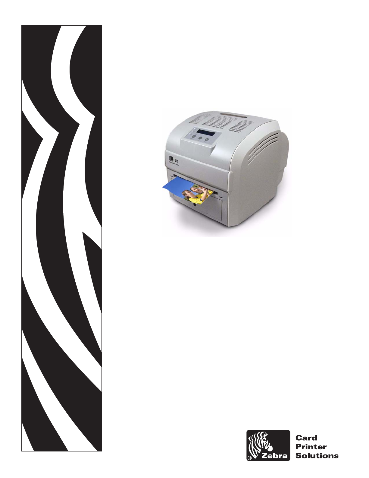
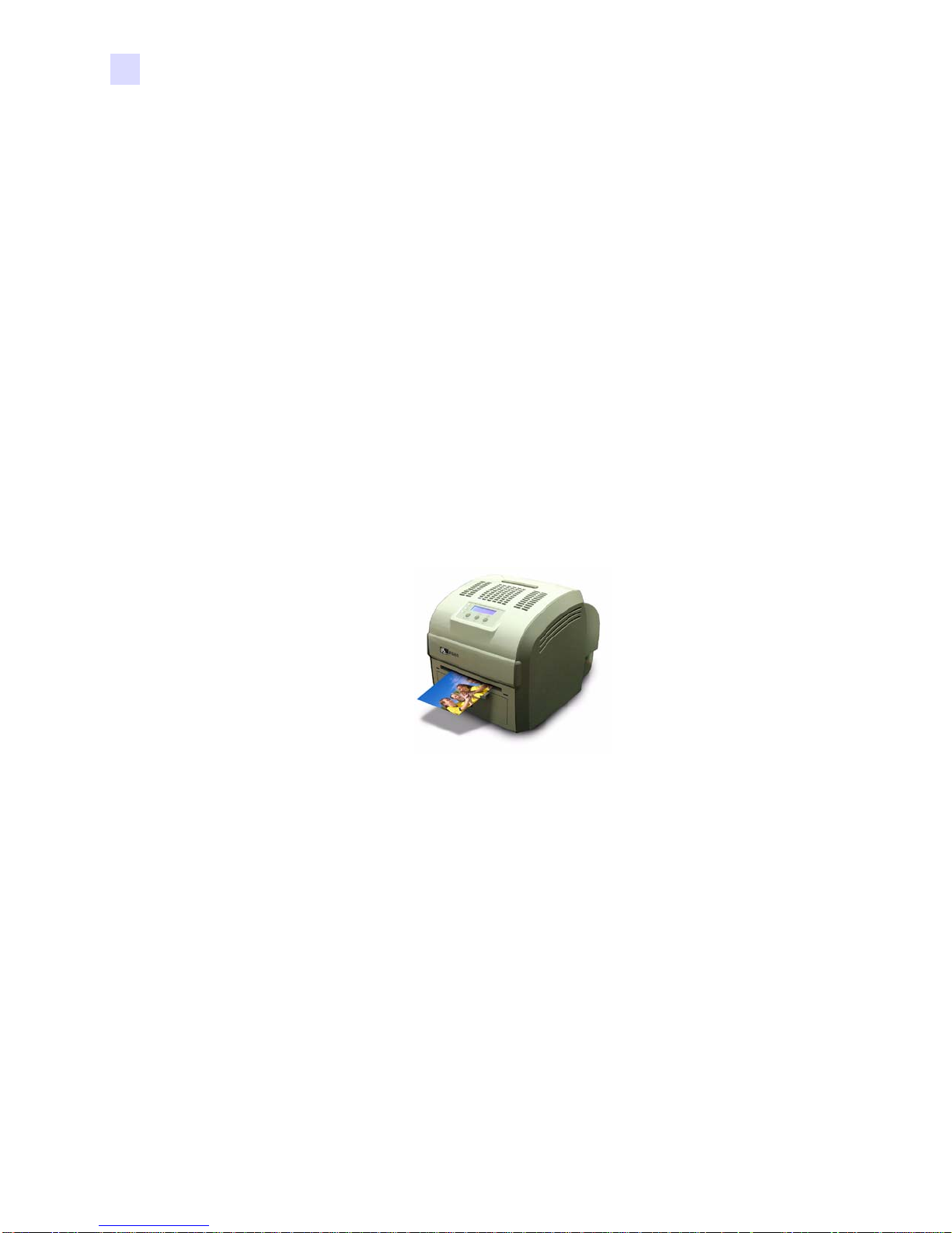
F680
Photo Printer
User’s Manual
Page 2
Page 3

This manual contains installation and operation information for the Zebra F6 80 Photo
Printer, manufactured by Zebra Technologies Corporation, Camarillo, California.
Return Materials Authorization
Before returning any equipment to Zebra Technologies Corporation for in-warranty or outof-warranty repair, contact Repair Administration for a Return Materials Authorization
(RMA) number. Repack the equipment in the original packing materia l and mark the RMA
number clearly on the outside. Ship the equipment, freight prepaid, to the address listed
below:
• For USA, Latin America, and Asia / Pacific:
Zebra Technologies Corporation
Zebra Card Printer Solutions
1001 Flynn Road
Camarillo, CA. 93012-8706.USA
Phone: +1 (805) 578-5001
FAX: +1 (805) 579-1808
Foreword
• For Europe and Middle East:
Zebra Technologies Corporation
Zebra Card Printer Solutions
Pittman Way, Fulwood
Preston, PR2 9ZD
Lancashire, U.K.
Phone: +44 - 1 - 772 - 797555
FAX: +44 - 1 - 772 - 693000
980588-001 Prelim 1 Zebra F680 Photo Printer User’s Manual iii
Page 4
Foreword
Copyright Notice
© 2007 ZIH Corp.
This document contains information proprietary to Zebra Technologies Corporation. This
document and the information contained within is Copyrighted by Zebra Technologies
Corporation and may not be duplicated in ful l or in part by any person without written
approval from Zebra. While every effort has been made to keep the information contained
within current and accurate as of the date of publication, no guarantee is given that the
document is error-free or that it is accurate with regard to any specificat ion. Zebra reserves the
right to make changes, for the purpose of product improvement, at any time.
Trademarks
F680 is a trademark and Zebra is a registered trademark of Zebra Technologies Corporation.
Windows and MS.DOS are registered trademarks of Microsoft Corp. All other trademarks or
registered trademarks are marks of their respective holders.
Product Disposal
Product Disposal Information • Do not dispose of this product in unsorted municipal
waste. This product is recyclable, and should be recycled according to your local
standards. For more information, please see our web site at:
http://www.zebra.com/environment
Declarations of Conformity
89/336/EEC
modified by
92/31/EEC and
93/68/EEC
73/23/EEC modified
by 93/68/EEC
1999/5/CE
EMC Directive
EMC Directive
EMC Directive EN55024 (2001)
Low voltage
Directive
R&TTE Directive
EN 55022 (1998) RF Emissions control
EN 301489-3 V1.4.1
EN 60950-1 (2001) Product safety
EN300330-2 V1.1.1 Radio Frequency Interferences
RF Emissions and Immunity for radio
equipment
Immunity to Electro-Magnetic
Disturbances
For a formal certificate, please contact the Compliance Office at Zebra’s Camarillo facility.
iv F680 User’s Manual 980588-001 Prelim 1
Page 5

EUROPE: Norway Only: This product is also designed for IT power system with phase to phase
voltage 230V. Earth grounding is via the polarized, 3-wire power cord.
FI: “Laite on liitettävä suojamaadoitus koskettimilla varustettuun pistorasiaan”
SE: “Apparaten skall anslutas till jordat uttag”
NO: “Apparatet må tilkoples jordet stikkontakt”
FCC Regulations
Model F680 has been tested and found to comply with the limits for a Class A digital device,
pursuant to Part 15 of the FCC Rules. These limits are designed to provide reasonable
protection against harmful interference when the equipment is operated in a commercial
environment. This equipment generates, uses, and can radiate radio frequency energy and, if
not installed and operated in accordance with the F680 User’s Manual, may cause harmful
interference to radio communications. Operation of this equipment in a residential area is
likely to cause harmful interference in which case the user will be required to correct the
interference at his own expense.
Pursuant to Part 15.21 of the FCC Rules, any changes or modifications to this equipment not
expressly approved by Zebra may cause harmful interference and void the FCC authorization
to operate this equipment.
Foreword
Industry Canada Notice
This device complies with Industry Canada ICES-003 class A requirements.
Cet equipement est conforme a l’ICES-003 classe A de la norm Industrielle Canadian.
980588-001 Prelim 1 F680 User’s Manual v
Page 6

Foreword
F680 Printer Model
The Zebra Product Number tells a story:
Here is a quick review of the Zebra Card Prin ter Seri es numbering and letterin g system to help
you.
Model numbers include identifiers that specify options using the following lettering
conventions:
Part Number Description
F 6 8 0 - _ _ _ _ _ - _ _ _
_ _ _ _ - 0 _ _ _ _ - _ _ _
_ _ _ _ - _ 0 _ _ _ - _ _ _
_ _ _ _ - _ _ 0 _ _ - _ _ _
_ _ _ _ - _ _ _ 0 _ - _ _ _
_ _ _ _ - _ _ _ _ A - _ _ _
_ _ _ _ - _ _ _ _ _ - A _ _
_ _ _ _ - _ _ _ _ _ - I _ _
_ _ _ _ - _ _ _ _ _ - _ D 0
Base Printer
F680 Digital Photo Printer
Built-in Options
None
Reserved
None
Reserved
None
Reserved
None
Interface
USB
Power Cord(s) Included
US 120 VAC
US 120 VAC and European 220 VAC
Windows Drivers and User Documentation CD
Included
vi F680 User’s Manual 980588-001 Prelim 1
Page 7
Icons
Foreword
Throughout this manual, different icons highlight important information, as follows:
Note • Indicates information that emphasizes or supplements important points of the main
text.
Important • Advises you of information that is essential to complete a task, or points out the
importance of specific information in the text.
Provides an example or scenario to demonstrate or clarify a section of text.
Electrostatic Discharge Caution • W arns you of the potential for electrostatic discharge.
Electric Shock Caution • Warns you of a potential electric shock situation.
Caution • Warns you of a situation where e xcessive heat could cause a burn.
Caution • Advises you that failure to take or avoid a specific action could result in
physical harm to you, or could result in physical damage to the hardware.
980588-001 Prelim 1 F680 User’s Manual vii
Page 8
Foreword
viii F680 User’s Manual 980588-001 Prelim 1
Page 9

Table of Contents
1 • Introduction. . . . . . . . . . . . . . . . . . . . . . . . . . . . . . . . . . . . . . . . . . 1
Printer Features . . . . . . . . . . . . . . . . . . . . . . . . . . . . . . . . . . . . . . . . . . . . . 1
Controls, Connectors, and Indicators. . . . . . . . . . . . . . . . . . . . . . . . . . . . . 3
2 • Installation and Setup. . . . . . . . . . . . . . . . . . . . . . . . . . . . . . . . . . 5
General Information . . . . . . . . . . . . . . . . . . . . . . . . . . . . . . . . . . . . . . . . . . 5
Unpacking the Printer. . . . . . . . . . . . . . . . . . . . . . . . . . . . . . . . . . . . . . . . . 6
Operating Location. . . . . . . . . . . . . . . . . . . . . . . . . . . . . . . . . . . . . . . . . . . 9
Opening the Printer Cover and Paper Door. . . . . . . . . . . . . . . . . . . . . . . 10
Loading Paper . . . . . . . . . . . . . . . . . . . . . . . . . . . . . . . . . . . . . . . . . . . . . .11
Initial Steps - 6 inch (15.3 cm) Wide Paper . . . . . . . . . . . . . . . . . . . . .11
Initial Steps - 5 inch (12.7 cm) Wide Paper . . . . . . . . . . . . . . . . . . . . 12
Subsequent Steps - Either Width Paper Roll . . . . . . . . . . . . . . . . . . . 15
Loading a Ribbon. . . . . . . . . . . . . . . . . . . . . . . . . . . . . . . . . . . . . . . . . . . 22
Closing the Paper Door and Printer Cover. . . . . . . . . . . . . . . . . . . . . . . . 27
Installing the Print Driver Software. . . . . . . . . . . . . . . . . . . . . . . . . . . . . . 28
Connecting Power . . . . . . . . . . . . . . . . . . . . . . . . . . . . . . . . . . . . . . . . . . 28
Connecting the Printer to the Computer. . . . . . . . . . . . . . . . . . . . . . . . . . 30
Attaching the Print Catcher . . . . . . . . . . . . . . . . . . . . . . . . . . . . . . . . . . . 31
Applying Power . . . . . . . . . . . . . . . . . . . . . . . . . . . . . . . . . . . . . . . . . . . . 32
Making a Test Print. . . . . . . . . . . . . . . . . . . . . . . . . . . . . . . . . . . . . . . . . . 33
Packing the F680 Photo Printer for Shipment . . . . . . . . . . . . . . . . . . . . . 34
3 • Printing . . . . . . . . . . . . . . . . . . . . . . . . . . . . . . . . . . . . . . . . . . . . 35
Setting Printer Properties. . . . . . . . . . . . . . . . . . . . . . . . . . . . . . . . . . . . . 35
Calibrating the Printer. . . . . . . . . . . . . . . . . . . . . . . . . . . . . . . . . . . . . . . . 35
980588-001 Prelim 1 F680 User’s Manual ix
Page 10

Table of Contents
4 • Cleaning. . . . . . . . . . . . . . . . . . . . . . . . . . . . . . . . . . . . . . . . . . . . 37
Cleaning the Printer . . . . . . . . . . . . . . . . . . . . . . . . . . . . . . . . . . . . . . . . . 38
Routine Maintenance . . . . . . . . . . . . . . . . . . . . . . . . . . . . . . . . . . . . . . . . 38
5 • Troubleshooting . . . . . . . . . . . . . . . . . . . . . . . . . . . . . . . . . . . . . 43
Resolving Potential Problems . . . . . . . . . . . . . . . . . . . . . . . . . . . . . . . . . 44
Resolving Operator Panel Error Messages . . . . . . . . . . . . . . . . . . . . . . . 45
Clearing a Paper Jam. . . . . . . . . . . . . . . . . . . . . . . . . . . . . . . . . . . . . . . . 46
Recovering from a Power Interruption . . . . . . . . . . . . . . . . . . . . . . . . . . . 46
6 • Technical Specifications . . . . . . . . . . . . . . . . . . . . . . . . . . . . . . 47
Physical Specifications. . . . . . . . . . . . . . . . . . . . . . . . . . . . . . . . . . . . . . . 47
Operating Environment . . . . . . . . . . . . . . . . . . . . . . . . . . . . . . . . . . . . . . 47
Power Requirements . . . . . . . . . . . . . . . . . . . . . . . . . . . . . . . . . . . . . . . . 47
Computer System Requirements. . . . . . . . . . . . . . . . . . . . . . . . . . . . . . . 48
Photo Dimensions . . . . . . . . . . . . . . . . . . . . . . . . . . . . . . . . . . . . . . . . . . 48
Cleaning the Platen Roller . . . . . . . . . . . . . . . . . . . . . . . . . . . . . . . . . 39
Cleaning the Thermal Print Head. . . . . . . . . . . . . . . . . . . . . . . . . . . . 41
Appendix A • Worldwide Service & Support . . . . . . . . . . . . . . . . . 49
Service and Support Locations . . . . . . . . . . . . . . . . . . . . . . . . . . . . . . . . 49
Website . . . . . . . . . . . . . . . . . . . . . . . . . . . . . . . . . . . . . . . . . . . . . . . . . . 50
x F680 User’s Manual 980588-001 Prelim 1
Page 11

Thank you for choosing the Zebra F680 Photo Printer. This manual guides you to efficient start
up and operation of your new Photo Printer.
Printer Features
1
Introduction
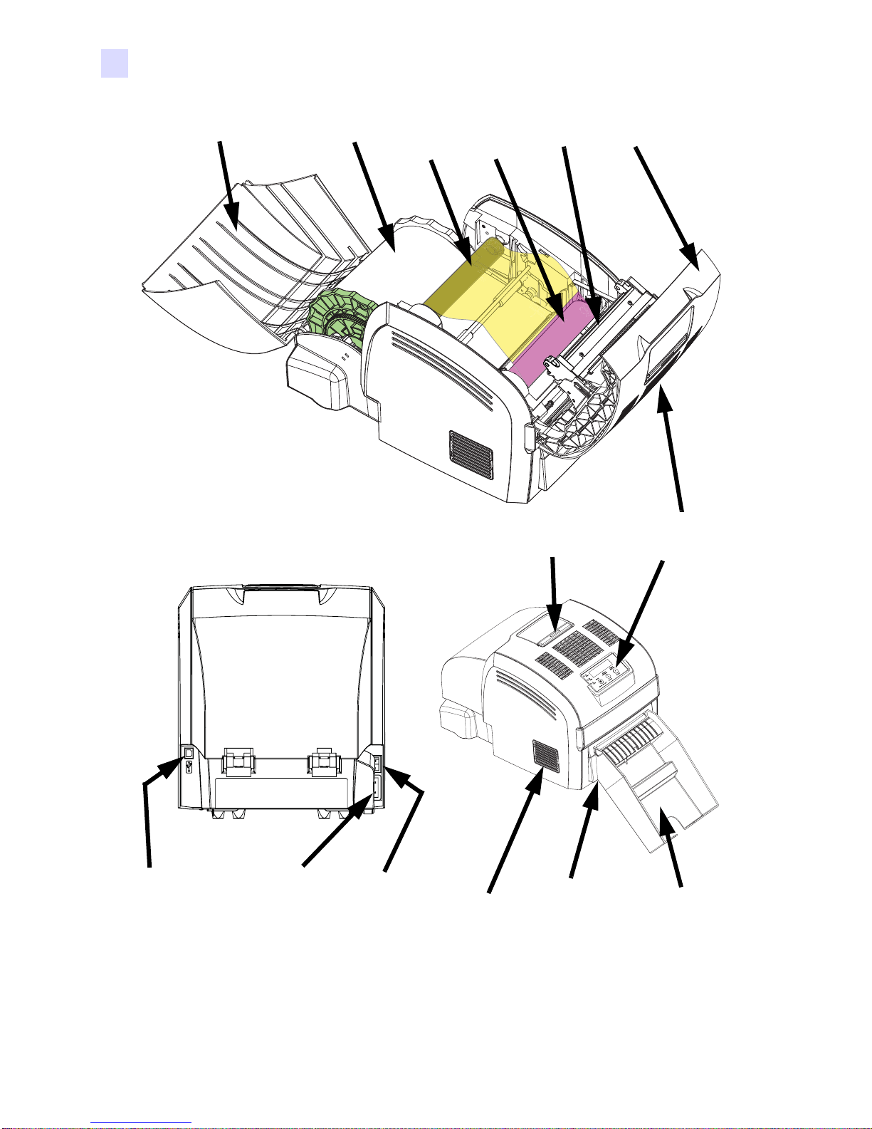
The following figure shows the main features of your F680 Printer. Section 2 of this manual
describes how to load the paper and ribbon, how to connect the Printer to your computer, and
how to install the Driver software onto your computer.
980588-001 Draft 1 Zebra F680 Photo Printer User’s Manual 1
Page 12
Introduction
Printer Features
Paper Door (Open)
Paper Roll
Ribbon
Takeup
Spool
Ribbon
Supply
Spool
Print
Head
Cover
Release
Cover
(Open)
Operator
Control
Panel
USB 2.0
Connecctor
2 Zebra F6 80 Photo Printer User’s Manual 980588-001 Draft 1
AC Power
Connector
Power
Switch
Air
Filter
Trim Tray
(under Print
Catcher)
Print
Catcher
Page 13
Controls, Connectors, and Indicators
The AC Power Connector, Power Switch, and USB 2.0 Connector are located on the rear of
the Printer, as shown in the previous figure.
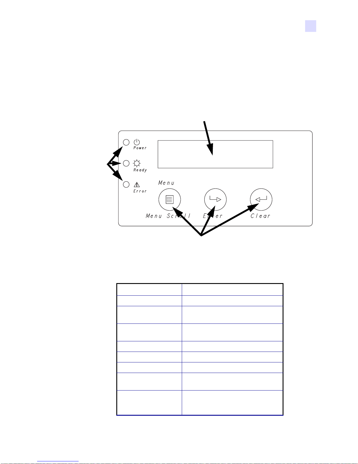
The Operator Control Panel (shown below ) includes three Indicator LEDs that indi cate system
status, three Control Buttons for scrolling through and selecting commands and options, and
an LCD Display Screen that indicates status and/or fault information.
Display Screen
Indcator
LEDs
Introduction
Controls, Connectors, and Indicators
Control Buttons
The LCD Display on the Operator Control Panel can display the following messages:
Message Meaning
Ready Printer is ready to print.
Warming Up Printer is not ready to print; allow it to
complete warming up.
Cooling Printer (typically the Print Head) is
too hot; allow it to cool down.
Cover Open Make sure Cover is evenly closed.
Check Ribbon Out of Ribbon - Load New Ribbon.
Paper Empty Load Paper.
Cutter Jam Check for paper jam where paper exits
printer.
Incorrect Ribbon Check for possible Ribbon Jam. Also
possible that Ribbon Barcode not
detected or incorrect.
980588-001 Draft 1 Zebra F680 Photo Printer User’s Manual 3
Page 14

Introduction
Controls, Connectors, and Indicators
Service 3.40.1
Service 3.40.5
Service 3.41.1
Service 3.41.2
Service 3.41.3
Service 3.41.4
Service 3.41.5
Service 3.41.6
Service 3.41.7
Service 3.42.1
Service 3.42.2
Service 3.42.3
Service 3.42.4
Service 3.42.5
Service 3.42.6
Service 3.42.7
Service 3.42.8
Service 3.42.9
Service 3.43.2
Service 3.43.4
Service 3.43.5
Service 3.43.7
Service 3.43.8
Service 3.43.9
Service 3.43.A
These Service Codes indicate an
internal problem. Report the code
number to your Zebra service
representative.
4 Zebra F6 80 Photo Printer User’s Manual 980588-001 Draft 1
Page 15

Installation and Setup
General Information
This section will guide you through the installation and setup of you r F680 Photo Printer.
This consists of the following procedures, which should be performed in the order
presented.
• Unpacking the Printer
• Connecting the Printer to the Power Source
• Connecting the Printer to the Computer
• Opening the Printer Cover and Paper Door
• Loading Paper
• Loading a Ribbon
• Closing the Printer Cover and Paper Door
• Attaching the Print Catcher
• Applying Power
• Loading the Printer Driver Software
• Making a Test Print
2
Instructions on packing the Printer for shipment are given at the end of this section.
The printer should be placed in a location that allows easy access to all sides. The printer
should never be operated while resting on its side or upside down.
980588-001 Prelim 1 Zebra F680 Photo Printer User’s Manual 5
Page 16
Installation and Setup
Unpacking the Printer
Electric Shock Caution • Limit AC power supplied to the F680 Printer to 110 ~ 230
volts, 60 ~ 50 Hz. Never operate the printer in a location where operator, computer, or
printer can get wet. Personal injury could result. The printer must be connected to a
grounded electrical power source and properly protected against electrical surges
and grounding faults; the electrical reliability of the printer is based on the reliability of
the power source and with ground connection.
The printer’s power supply is an internal unit that can only be serviced or replaced by
trained and authorized personnel.
Unpacking the Printer
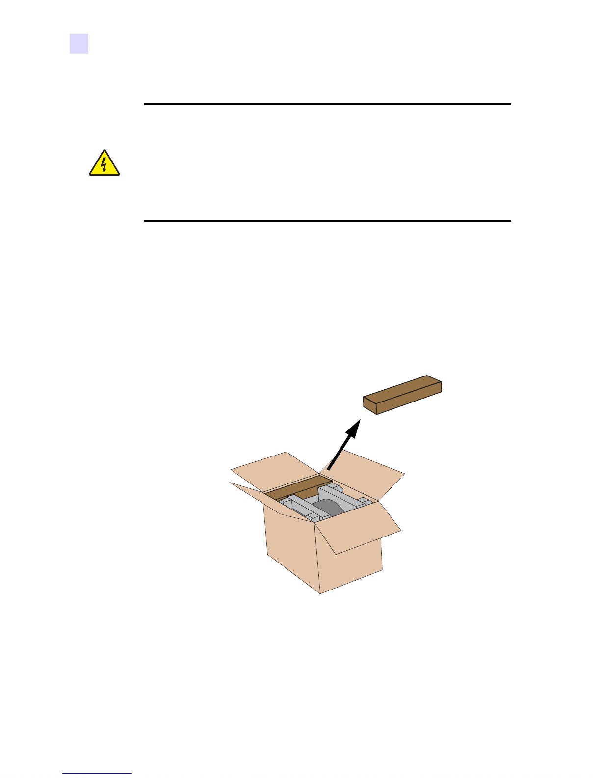
Your F680 Photo Printer ships in a carton and protective anti-static bag. Keep all packaging
material in case you need to move or re-ship the printer.
1. Inspect the shipping container to ensure that no damage has occurred during shipment. If
any damage is apparent, file a claim with the shipper.
2. Open the shipping carton. Remove the Accessories Box.
Accessories
Box
6 Zebra F6 80 Photo Printer User’s Manual 980588-001 Prelim 1
Page 17
Installation and Setup
Unpacking the Printer
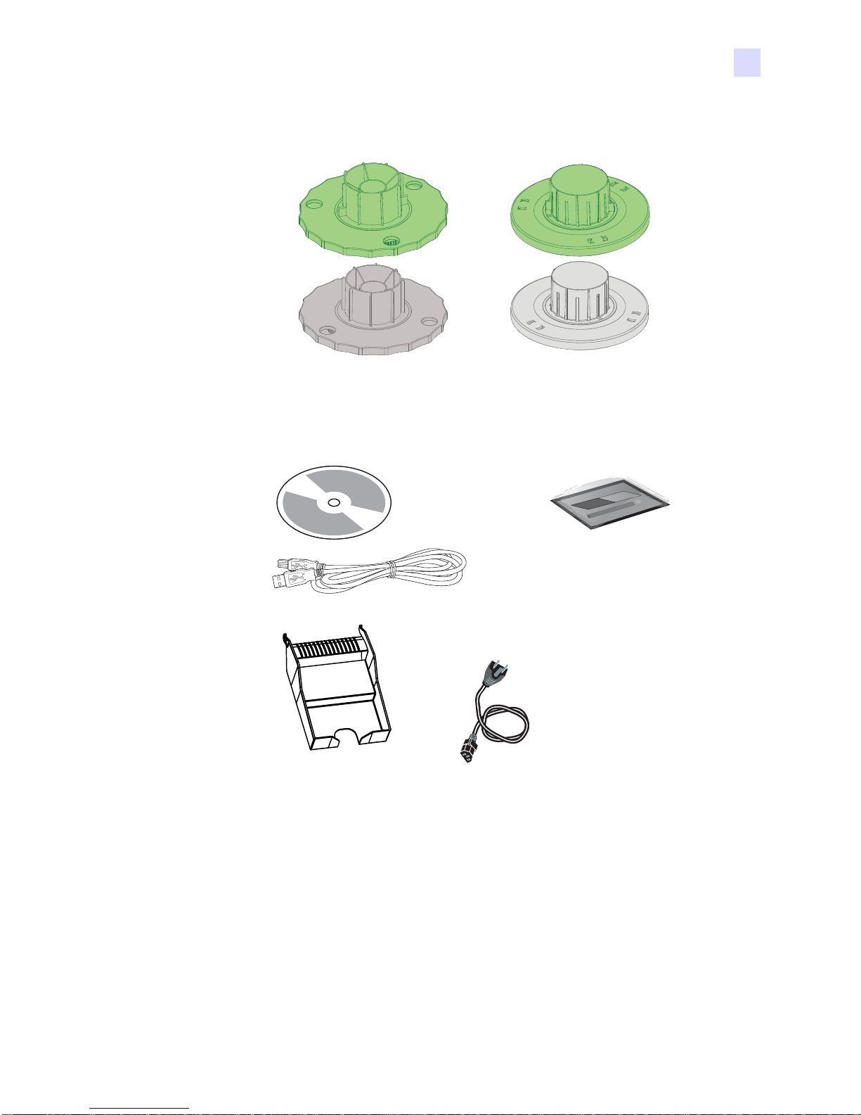
3. Open the Accessories Box, and verify that the following nine items are included:
Hubs
(Used for loading
either 6” or 5” wide
paper rolls)
Catch Tray
Driver &
Documentation
CD
USB
Cable
Spacers
(Used in addition
to Hubs for loading
of 5” wide paper
rolls only)
Cleaning Kit
(Includes a Cleaning
Card and a Cleaning
Swab)
AC Power Cord
(Type depends on
Printer Model
oredered)
If any items are missing, please contact your dealer. To reorder, please refer to Appendix D of
this manual.
980588-001 Prelim 1 Zebra F680 Photo Printer User’s Manual 7
Page 18
Installation and Setup
Unpacking the Printer
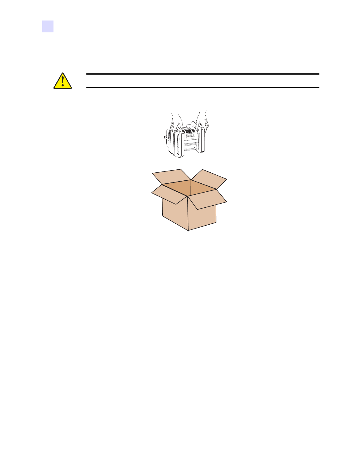
4. Use both hands to lift the Printer (in the foam inserts) from the shipping carton.
Caution • The F680 Printer weighs approximately 20 lbs (9 kg).
Keep all the packing and shipping material in case you have to transport the Printer. If the
shipping material is damaged or misplaced, replacement material can be ordered at nominal
cost (refer to Appendix D of this manual).
8 Zebra F6 80 Photo Printer User’s Manual 980588-001 Prelim 1
Page 19

Operating Location
1. Please ensure that you have a clean and nearly dust free environment for proper operation
and storage of the printer.
2. The following figure shows minimum space requirements for the Printer (including space
for installing the paper and ribbon, and allowing space for sufficient free air circulation).
In addition, the front of Printer should be located with in appproximate ly 2 inches (50 mm)
of the work surface, since the Catch Tray extends below the bottom of the Printer.
Installation and Setup
Operating Location
Approx. 34" (860 mm)
Approx. 17.5" (440 mm)
Approx. 17.7"
(450 mm)
980588-001 Prelim 1 Zebra F680 Photo Printer User’s Manual 9
Page 20

Installation and Setup
Opening the Printer Cover and Paper Door
Opening the Printer Cover and Paper Door
1. With the heel of your hand, press down on the rectangular bar as shown in the figure
below. You will hear a “click” and the rear edge of the Printer Cover wil l raise sli gh tly, as
shown.
2. Swing the Cover forward, then lift and swing the Paper Door by its front edge.
1
2
10 Zebra F680 Photo Printer User’s Manual 980588-001 Prelim 1
Page 21

Loading Paper
Important • The initial steps for loading paper are diff eren t fo r 6 inch (1 5. 3 cm) wide or 5
inch (12.7 cm) paper rolls.
The initial steps for 6 inch (15.3 cm) wide paper are given below.
Initial steps for 5 inch (12.7 cm) wide paper are given starting on page 12.
Subsequent steps that are the same for either width paper are gi ven starting on .
Initial Steps - 6 inch (15.3 cm) Wide Paper
1. Note that there is a green hub and a gray hub (if necessary, see the figure on page 7 to
make sure you have the hubs and not the spacers).
2. In the drawing below, note that there are “lugs” on the green hub and no lugs on the gray
hub. Otherwise the gray and green hubs are identical. There a re not che s on one end of the
paper core, and no notches on the other end.
Installation and Setup
Loading Paper
Lugs
Notches
No Notches
No Lugs
980588-001 Prelim 1 Zebra F680 Photo Printer User’s Manual 11
Page 22

Installation and Setup
Loading Paper
3. Press the green hub into the paper roll so the lugs are fully engaged in the notches and the
flat (inner) surface of the hub is flush against the paper roll. Similarly, press the gray hub
into the other end of the paper roll.
Initial Steps - 5 inch (12.7 cm) Wide Paper
To use 5 inch (12.7 cm) wide paper rolls in the F680 Photo Printer, spacers are used between
the hubs and either side of the paper spool to make the effective width the same as for 6 inch
(15.3 cm) paper rolls.
1. Note that the green hub and spacer have lugs, and the gray hub and spacer do not have
lugs, as shown below.
Green Hub has Lugs
Gray Hub has no Lugs
12 Zebra F680 Photo Printer User’s Manual 980588-001 Prelim 1
Green Spacer has Lugs
Gray Spacer has no Lugs
Page 23

Installation and Setup
Loading Paper
2. Snap the green hub and space r together, and snap the gray hub and spacer together, as
shown below.
980588-001 Prelim 1 Zebra F680 Photo Printer User’s Manual 13
Page 24

Installation and Setup
Loading Paper
3. Insert the green hub/spacer into the paper core so the lugs on the spacer engage the
notches on the paper core. Similarly, insert the gray hub/spacer into the other end of the
paper core.
14 Zebra F680 Photo Printer User’s Manual 980588-001 Prelim 1
Page 25

Subsequent Steps - Ei ther Width Paper Roll
1. Slide the Paper Width Guides to the appropriate position for the width of the paper roll
you will be loading. If your paper roll is six inches (15.3 cm) wide, slid e the guides to the
outer (“6”) position; if your paper roll is five i nches (12.7 cm) wide, slide the guides to the
inner (“5”) position.
Installation and Setup
Loading Paper
6” (15.3 cm) Paper
Width Position
5” (12.7 cm) Paper
Width Position
980588-001 Prelim 1 Zebra F680 Photo Printer User’s Manual 15
Page 26

Installation and Setup
Loading Paper
2. Note the location of the paper spool slots on either side of the Printer.
Paper Spool Slots
16 Zebra F680 Photo Printer User’s Manual 980588-001 Prelim 1
Page 27

Installation and Setup
Loading Paper
3. Put the Paper Roll (with its hubs or hubs and spacers, depending on the width of the paper
roll) so the round axle ends of the hubs fit within the Pape r Spool Slots, as shown in the
following figure. The end of the Paper Roll in the green hub (with the lugs/not ches) must
go into the slot on the near side of the Printer, as shown below. Make sure the Paper Roll
seats fully and evenly in the slots.
980588-001 Prelim 1 Zebra F680 Photo Printer User’s Manual 17
Page 28

Installation and Setup
Loading Paper
4. Remove the sticker securing the end of the Paper Roll, and lift the leading edge of the
paper.
18 Zebra F680 Photo Printer User’s Manual 980588-001 Prelim 1
Page 29

Installation and Setup
Loading Paper
5. T o guide the paper through its path, it is preferable to unroll the paper by turning the green
hub. (It is ok to pull the leading edge of t he p ap er d urin g t he in iti al l oa din g, but its a good
habit to get into to avoid touching the surface of the paper.)
980588-001 Prelim 1 Zebra F680 Photo Printer User’s Manual 19
✓
Page 30

Installation and Setup
Loading Paper
6. Feed the paper under the Pinch Rollers and the Paper Guide, as shown below.
Pinch Rollers
Paper Guide
20 Zebra F680 Photo Printer User’s Manual 980588-001 Prelim 1
Page 31

Installation and Setup
Loading Paper
7. Continue feeding the paper until approximately one to three inches (25 to 75 mm) of paper
sticks out from the front of the Printer.
1 - 3 "
(25 - 75 mm)
980588-001 Prelim 1 Zebra F680 Photo Printer User’s Manual 21
Page 32

Installation and Setup
Loading a Ribbon
Loading a Ribbon
Important • Use only genuine Zebra ribbons in the F680 Photo Printer; use of other ribbons
can result in poor-quality prints and can even damage the Printer.
Important • Images remain on the ribbon after printing. If you need to maintain
confidentiality, dispose of the used ribbon appropriately.
1. If you are replacing a ribbon, remove the old ribbon and the supply and takeup spools.
2. Remove the protective wrapping and the paper band from the ribbon. Unroll about 7
inches (175 mm) of ribbon from the supply spool, as shown in the figure below.
22 Zebra F680 Photo Printer User’s Manual 980588-001 Prelim 1
7 ± 1 in
(175 ± 25 mm)
Page 33

Installation and Setup
Loading a Ribbon
3. Note that one end of the supply spool extends from the ribbon and has a bar-code pattern
on it. That end of the supply spool will be placed into po siti on first, follo wed b y th e ot her
end of the supply spool.
No barcode
on this end
End of Supply
Spool with
Barcode goes
onto this spindle
980588-001 Prelim 1 Zebra F680 Photo Printer User’s Manual 23
Page 34

Installation and Setup
Loading a Ribbon
4. See the following figures and position the ribbon supply spool on i ts spindles.
1. While holding the ribbon
takeup spool with one hand
(typically the left hand for a righthanded person), use your right
hand to press the barcode end of
the ribbon supply spool onto the
spindle on the right.
2. As the spool
compresses the
spindle spring,
lower the other end
of the ribbon supply
spool so it can
engage the spindle
on the left side.
24 Zebra F680 Photo Printer User’s Manual 980588-001 Prelim 1
3. Rotate the spool back
and forth so it fully
engages both spindles
and is pressed against
the left side spindle.
Page 35

Installation and Setup
Loading a Ribbon
5. Check that the ribbon supply spool is fully engaged on both spindles (especially the one
on the left side.)
✓
X
X
980588-001 Prelim 1 Zebra F680 Photo Printer User’s Manual 25
Page 36

Installation and Setup
Loading a Ribbon
6. Then position the ribbon take-up spool on the other spindles.
X
7. If there is an excessive amount of slack in the ribbon (i.e., it appears that the ribbo n will
become tangled with the paper or elsewhere in the Printer), take up the slack by turning
the ribbon supply spool only. Do not turn the ribbon takeup spool in either direction.
26 Zebra F680 Photo Printer User’s Manual 980588-001 Prelim 1
Page 37

Closing the Paper Door and Printer Cover
Closing the Paper Door and Printer Cover
Swing the Paper Door to its closed position, then swing the Printer Cover closed. Press down
evenly until the Printer Cover snaps closed.
Installation and Setup
1
2
980588-001 Prelim 1 Zebra F680 Photo Printer User’s Manual 27
Page 38

Installation and Setup
Installing the Print Driver Software
Installing the Print Driver Software
Printing with the F680 Photo Printer requires the Windows Printer Driver and your card
design/issuing software or printer command level programming through the printer interface.
To install the Windows Printer Driver onto your computer, insert the included Driver and
Documentation CD into your computer’s CD-ROM drive and follow the screen prompts.
Connecting Power
The F680 Printer contains an auto-detecting and switching power supply. Input voltage and
frequency can be in either of the following ranges:
• 90 - 132 VAC at 48 - 62 Hz
• 180 - 264 VAC at 48 - 62 Hz
A three-wire (grounding) Power Cord is included with the Printer. If the in cl uded Power Cord
is not appropriate for your voltage and/ or source out let, be sure to obtain an appropri ate Power
Cord before proceeding.
Important • Verify that the Power Switch is set to OFF (O).
Caution • The AC power outlet must be grounded and a three-wire Power Cord must be
used. An ungrounded outlet can cause fire, electric shock, or harmful interference to
nearby electrical devices.
28 Zebra F680 Photo Printer User’s Manual 980588-001 Prelim 1
Page 39

Installation and Setup
Connecting Power
Power Switch
AC Power
Connector
1. Connect the Power Cord to the AC Power Connector on the back of the Printer (see above
figure) and to a grounded AC power outlet.
980588-001 Prelim 1 Zebra F680 Photo Printer User’s Manual 29
Page 40

Installation and Setup
Connecting the Printer to the Computer
Connecting the Printer to the Computer
The F680 Printer includes a standard USB 2.0 interface.
Important • Verify that the Power Switch is set to OFF (O)
USB
1. Connect the USB Cable included with the Printer to the USB 2.0 Connector o n the back of
the Printer and to the USB 2.0 Connector on the computer.
30 Zebra F680 Photo Printer User’s Manual 980588-001 Prelim 1
Page 41

Attaching the Print Catcher
The Print Catcher attaches to the front of the Printer and provides a receptacle for completed
prints.
The Print Catcher simply hooks into slots in the front of the Printer. Note that when the Print
Catcher is attached, it extends below the bottom level of the Printer; the Print Catcher would
normally hang over a desk or table edge.
Installation and Setup
Attaching the Print Catcher
980588-001 Prelim 1 Zebra F680 Photo Printer User’s Manual 31
Page 42

Installation and Setup
Applying Power
Applying Power
1. Verify that the Printer’s power cord is plugged into a grounded AC outlet, and that the
USB 2.0 Connector on the Printer is connected to a USB 2.0 Port on your computer.
2. Set the Power Switch to On ( I ).
USB
90 - 264 VAC
3. The Power LED on the Operator Control Panel will light. The Printer will perform an
initialization and self-test routine; at successful complet ion of this ro utine the Rea dy LED
will light and the message Ready will display.
32 Zebra F680 Photo Printer User’s Manual 980588-001 Prelim 1
Ready
Page 43

Making a Test Print
Making a test print is a simple way to verify basic operation of the Printer.
1. Set the Printer power to ON (I). The Power LED on the front panel will glow orange.
2. The Printer will run through an initialization and self-test. At successful completion, the
Ready LED on the front panel will glow green and the message Ready will display on the
LCD panel.
Installation and Setup
Making a Test Print
Ready
3. Press the Menu Scroll button several times, until Test Print Mode displays on the LCD
Panel, then press the Enter button.
Test Print Mode
4. Press the Menu button several times, until Pattern appears on the LCD Panel, then press
the Enter button.
980588-001 Prelim 1 Zebra F680 Photo Printer User’s Manual 33
Page 44

Installation and Setup
Packing the F680 Photo Printer for Shipment
5. Press the Menu button several times to scroll through the choices of pattern. The choices
are::
•Mid Gray
• Grid on Gray
• 1 Pixel Grid
• 2 Pixel Grid
• Max (maximum) Gray
•Offset Dots
• Smear
Pattern
6. When the desired pattern is displayed on the LCD Panel, press the Enter button. The
Printer will print a “picture” with that pattern.
Packing the F680 Photo Printer for Shipment
If the F680 Photo Printer is to be shipped, it is important to use the original packing and
shipping material to prevent damage to the Printer. If the original material is lost, a
replacement Shipping Kit can be ordered from Zebra; please refer to the Media List on the
Windows Drivers and User Documentation CD supplied with this printer.
34 Zebra F680 Photo Printer User’s Manual 980588-001 Prelim 1
Page 45

3
Printing
Printing with the F680 Photo Printer is similar to printing with any other printer in a
Windows environment.
Setting Printer Properties
Printer Properties can be set either at the Operating System level or within the application
software program used for printing.
Calibrating the Printer
The provided Calibration Utility (on the Driver and Documentation CD) will help you get
the best quality prints from the P680 Phot o Printer.
The factory default calibration values generally provide excellent prints. However, if you
are dissatisfied with the color of your prints, run the Calibration Utility.
To run the Calibration Utility, insert the CD, click on Calibration Software, and follow
the on-screen prompts.
980588-001 Prelim 1 Zebra F680 Photo Printer User’s Manual 35
Page 46

Printing
Calibrating the Printer
36 Zebra F680 Photo Printer User’s Manual 980588-001 Prelim 1
Page 47

4
Cleaning
To ensure good performance and high-quality prints, make sure that the F680 Photo
Printer and its environment are clean and dust free.
Caution • Never use abrasives or harsh chemicals to clean an y parf of the Prin ter. Do not
allow any foreign objects or liquids to fall or spill inside the printer. Fire or electric shock
could result. If any foreign object enters the printer , turn of f the printer power imme diately,
disconnect the power cord, and contact your supplier or Zebra Technologies.
980588-001 Prelim 1 Zebra F680 Photo Printer User’s Manual 37
Page 48

Cleaning
Cleaning the Printer
Cleaning the Printer
Clean the exterior of the Printer and the filter opening regular to eliminate dust buildup and
prevent dirt from entering the Printer.
1. Wipe the exterior of the Printer with a damp, lint-free clot h.
2. Vacuum the filter opening and the area above the Print Head to remove any dust.
Area Above the
Print Head
Filter Opening
Routine Maintenance
Note • If paper and/or ribbon are loaded in the Printer, remove them before performing
maintenance procedures.
To maintain good print quality:
1. Clean the Platen Roller if you notice artifacts (tiny spots; usually white) on your prints.
2. Clean the Thermal Print Head if directed to do so by a Zebra service representative.
38 Zebra F680 Photo Printer User’s Manual 980588-001 Prelim 1
Page 49

Cleaning the Platen Roller
Clean the Platen Roller and Pick Rollers if you notice artifacts (tiny spots; usually white) on
your prints.
1. Make sure the printer power is set to OFF (O).
2. Open the Cover and the Paper Doo r.
3. If Ribbon and Paper are installed in the Prin ter, remove them both and set aside (they will
be re-installed in the Printer after the Platen Roller and Pick Rollers are cleaned).
4. In turn, slide the Paper Guides toward th e center and remove them by lifting up on the
back edge of the Guide.
Paper
Guides
Cleaning
Routine Maintenance
Lift
Back
Edge
5. Peel off the protective covering from both sides of the Cleaning Card.
980588-001 Prelim 1 Zebra F680 Photo Printer User’s Manual 39
Page 50

Cleaning
Routine Maintenance
6. Slide the white (adhesive) end of the Cleaning Card under one of the white Pick Rollers.
Note • The Cleaning Card will be a VERY snug fit under the Pick Roller.
Pick
Rollers
Cleaning
Card
7. Slide the Cleaning Card straignt inward over the Platen Roller so the adhesive surface of
the Cleaning Card remains under the Pick Roller.
Pick
Rollers
Platen
Roller
40 Zebra F680 Photo Printer User’s Manual 980588-001 Prelim 1
Page 51

Cleaning
Routine Maintenance
8. Remove the Cleaning Card by sliding it straight out.
9. Using the same Cleaning Card, repeat steps 6 through 8 for the other Pick Roller.
10. Replace the Paper Guides by engaging the lip on the inside of the back edge and then
rotating it forward and down until it snaps into place.
11. Replace the Paper and Ribbon.
Cleaning the Thermal Print Head
Important • Do not perform this procedure unless you have been directed to do so by a Zebra
service representative.
1. Make sure the printer power is set to OFF (O).
2. Open the Printer Cover.
Caution • The Thermal Print Head becomes extremely hot during normal o peration. W ait
five minutes after you open the Printer Cover before you begin cleaning the head.
Caution • Oil from fingerprints can damage the Print Head, which looks like a glass bar .
Never touch it with your bare hands or fingers.
980588-001 Prelim 1 Zebra F680 Photo Printer User’s Manual 41
Page 52

Cleaning
Routine Maintenance
3. Remove the Cleaning Swab from the Cleaning Kit. Bend the Swab to release alcohol to
the tip.
4. Move the tip of the Cleaning Swab along the entire length of the Thermal Print Head and
the Peel Bar. (Note that the picture below shows the inside of the Printer with the Ribbon
and Paper removed; they do not need to be removed to perform this cleaning.)
Peel
Bar
Thermal
Print
Head
5. Wait five minutes for any residual alcohol to evaporate befo re applying power.
42 Zebra F680 Photo Printer User’s Manual 980588-001 Prelim 1
Page 53

5
Troubleshooting
The table on the next page offers causes and solutions to symptoms related to improper
operation. Check the table when experiencing any loss of operation o r print quality.
980588-001 Prelim 1 Zebra F680 Photo Printer User’s Manual 43
Page 54

Troubleshooting
Resolving Potential Problems
Resolving Potential Problems
Problem / Symptom Description or Cause Possible Solution
Paper jam; Error indicator is on,
Printer does not operate.
Prints have linear streaks. Thermal Print Head is dirty. If directed by your Zebra service
Prints have streaks of small dots. The Platen Roller is dirty. Clean the Platen Roller. See
Print size or aspect ratio is not
what you expected.
Paper is jammed in the Printer. Clear the paper jam. See
“Clearing a Paper Jam” on
page 46
representative, clean the Thermal
Print Head. See “Cleaning the
Thermal Print Head” on page 41
“Cleaning the Platen Roller” on
page 39
The image file or printing options
need to be adjusted in your photo
printing software program.
In your photo printing software
program:
• Use Fit To Page or Clip
options if available.
• Adjust the image size to match
the paper size.
• Makes sure the Portrait /
Landscape setting matches the
orientation of the image.
• For more information, see the
help file or documentation for
your photo printing software
program.
Note: It is not necessary to adjust
the image resolution (dpi) to
match the printer resolution. The
Printer Driver automatically
scales your image to match the
Printer resolution.
Insufficient Memory errors
occur on your computer after
making a substantial number of
prints.
44 Zebra F680 Photo Printer User’s Manual 980588-001 Prelim 1
Your computer may be low on
RAM (Random Access Memory)
and/or disc caching memory.
This occurs when you rotate,
scale, or retouch high resolution
images (i.e., over 72 dpi).
• Minimize the number of
images open at the same time.
• Delete the contents of the
clipboard frequently.
• Close all programs except the
photo printing software
program.
• See the help f ile or
documentation for your photo
printing software program for
tips on memory optimization.
•See page 48 of this document
for system requirements.
Page 55

Resolving Operator Panel Error Messages
Resolving Operator Panel Error Messages
Error Message Description or Cause Possible Solution
Troubleshooting
Paper Empty The paper roll has been
completely used up or is not
loaded.
Check Ribbon The ribbon is completely used
up, is not loaded, or is stuck to
the paper.
Check Paper The paper is stuck in the Printer
or paper path.
Cover Open The Printer cover is open. Make sure that the cover is
Incorrect Ribbon The Printer could not read the bar
code on the ribbon supply spool.
W a rming Up The Printer is warming up, and is
not ready to print.
Cooling The Printer is too hot to print, and
is cooling down.
Cutter Jam The paper cutter did not move
completely to one side.
Load the paper. See “Loading
Paper on page 11.
Load the ribbon. See “Loading a
Ribbon” on page 22.
Clear the Paper Jam. See
“Clearing a Paper Jam” on
page 46
completely and securely closed.
Check that the ribbon has a bar
code and/or replace the ribbon.
See”Loading a Ribbon” page 22
Wait for the Printer to complete
warming up.
Wait for the Printer to complete
cooling.
Check the paper path for a jam.
Service XX.YY.ZZ The Printer requires service. Contact your Zebra service
representative. Have available:
•Error Code Number
(XX.YY.ZZ)
• Printer Model Number and
Serial Number (shown on the
Printer’s data plate)
980588-001 Prelim 1 Zebra F680 Photo Printer User’s Manual 45
Page 56

Troubleshooting
Clearing a Paper Jam
Clearing a Paper Jam
1. Turn off the Printer and then turn it back on.
2. If a Paper Jam message appears on the Operator Panel after the Printer reaches the Ready
state, continue with this procedure.
3. Turn off the Printer, and open the cover.
4. Remove the ribbon.
Caution • Do not pull abruptly on the paper. This could cause damage to the Printer.
5. Open the paper door.
6. Slowly and carefully pull the damaged paper out of the Printer.
7. Use a pair of scissors to cut off any damaged, wrinkled, or torn portion of the paper. Cut
the paper smoothly and reasonably close to straight across the paper.
Note • Do not damage or mark any of the rollers.
8. Reload the paper.
9. Reload the ribbon.
10. Closee the paper door and the cover. Turn on the Printer and resume printing.
Recovering from a Power Interruption
Caution • If the Printer loses power while printing, the Printer will stop with the Thermal
Print Head positioned against the platen roller. The platen roller could become deformed
and damaged if the Thermal Print Head is left in this position.
If a power interruption occurs:
1. Open the cover immediately to release the pressure on the platen roller. Leave the cover
open until power is restored.
2. When power is restored, restart the Printer by following the procedure for Clearing a
Paper Jam on page .
3. Send the print job to the Print er again.
46 Zebra F680 Photo Printer User’s Manual 980588-001 Prelim 1
Page 57

Technical Specifications
Physical Specifications
Dimensions: Width 11.4 in. (290 mm)
6
Depth 19.6 in. (496 mm)
Height (13.6 in.) (346 mm)
Weight 20 lbs (9 kg) (without ribbon and paper)
Operating Environment
Temperature: 50 to 95° F (+10 to +35° C)
Relative Humidity:20 to 80%
Power Requirements
Voltage/Frequency (auto detection of the following ranges):
90 V to 132 V / 48 Hz to 62 Hz
180 V to 264 V / 48 Hz to 62 Hz
Power Consumption: 320 watts maximum
980588-001 Prelim 1 Zebra F680 Photo Printer User’s Manual 47
Page 58

Technical Specifications
Computer System Requirements
Computer System Requirements
• Microsoft Windows 2000 or Microsoft Windows XP Operating System
• Minimum 1.0 GHz Pentium III Microprocessor
• Minimum 128 MB of RAM
• Minimum 2GB of available hard disk space
• USB 2.0 compliant host device
Photo Dimensions
• 4 x 6 in. (10 x 15 cm)
• 6 x 8 in. (15 x 20 cm) with border
• 6 x 8 in. (15 x 20 cm) borderless
48 Zebra F680 Photo Printer User’s Manual 980588-001 Prelim 1
Page 59

Worldwide Service &
Service and Support Locations
North America Region
APPENDIX A
Support
Zebra Technologies
Card Printer Solutions Headquarters
1001 Flynn Road
Camarillo, CA 93012-8706 USA
Phone: 800-511-9909
e-mail: techsupport@zebra.com
Europe, Middle East, and Africa Region
Zebra Technologies
Card Printer Solutions, Europe, Middle East, Africa
The Valley Centre, Gordon Road, High Wycombe
Buckinghamshire HP13 6EQ, England
Phone: + 44 (0) 870 241 1527 (from outside U.K.)
Phone: 0870 241 1527 (from inside U.K.)
e-mail: cardts@zebra.com
980588-001 Draft 1 Zebra F680 Photo Printer User’s Manual 49
Page 60

Worldwide Service & Support
Website
Latin America Region
Zebra Technologies
Card Printer Solutions, Latin America
9800 NW 41st Street, Suite 220
Doral, FL 33178 USA
Fax: + 1 (305) 558-8485
e-mail: techsupport@zebra.com
Asia Pacific Region
Zebra Technologies Asia Pacific, LLC
16 New Industrial Road
#05-03 Hudson TechnoCentre
Singapore 536204
Phone: + 65 6885 0833
Website
Fax: + 65 6885 0836
e-mail: esoh@zebra.com
www.zebracard.com
50 Zebra F680 Photo Printer User’s Manual 980588-001 Draft 1
 Loading...