

Page 1

DS9308
Imaging Scanner
Product Reference
Guide
MN-003532-04EN Rev. A
Page 2

Copyright
ZEBRA and the stylized Zebra head are trademarks of Zebra Technologies Corporation, registered in many
jurisdictions worldwide. All other trademarks are the property of their respective owners.
©2021 Zebra Technologies Corporation and/or its affiliates. All rights reserved.
COPYRIGHTS & TRADEMARKS: For complete copyright and trademark information, go to
zebra.com/copyright
.
WARRANTY: For complete warranty information, go to zebra.com/warranty
END USER LICENSE AGREEMENT: For complete EULA information, go to zebra.com/eula
For Australia Only
For Australia Only. This warranty is given by Zebra Technologies Asia Pacific Pte. Ltd., 182 Cecil Street, #08-01
Frasers Tower, Singapore 069547. Our goods come with guarantees that cannot be excluded under the Australia
Consumer Law. You are entitled to a replacement or refund for a major failure and compensation for any other
reasonably foreseeable loss or damage. You are also entitled to have the goods repaired or replaced if the goods
fail to be of acceptable quality and the failure does not amount to a major failure.
Zebra Technologies Corporation Australia’s limited warranty above is in addition to any rights and remedies you
may have under the Australian Consumer Law. If you have any queries, please call Zebra Technologies
Corporation at +65 6858 0722. You may also visit our website: zebra.com
Terms of Use
• Proprietary Statement
This manual contains proprietary information of Zebra Technologies Corporation and its subsidiaries
(“Zebra Technologies”). It is intended solely for the information and use of parties operating and
maintaining the equipment described herein. Such proprietary information may not be used, reproduced,
or disclosed to any other parties for any other purpose without the express, written permission of Zebra
Technologies.
• Product Improvements
Continuous improvement of products is a policy of Zebra Technologies. All specifications and designs are
subject to change without notice.
• Liability Disclaimer
Zebra Technologies takes steps to ensure that its published Engineering specifications and manuals are
correct; however, errors do occur. Zebra Technologies reserves the right to correct any such errors and
disclaims liability resulting therefrom.
• Limitation of Liability
In no event shall Zebra Technologies or anyone else involved in the creation, production, or delivery of the
accompanying product (including hardware and software) be liable for any damages whatsoever
(including, without limitation, consequential damages including loss of business profits, business
interruption, or loss of business information) arising out of the use of, the results of use of, or inability to
use such product, even if Zebra Technologies has been advised of the possibility of such damages. Some
jurisdictions do not allow the exclusion or limitation of incidental or consequential damages, so the above
limitation or exclusion may not apply to you.
.
.
for the most updated warranty terms.
2
Page 3

Revision History
Changes to the original guide are listed below:
Change Date Description
-01 Rev A 09/2019 Initial release.
-02 Rev A 12/2019 Updated defaults for Parity and ASCII Format in Terminal Specific RS-232 Table;
-03EN Rev A 6/2020 - Updated Data Formatting: ADF, MDF, Preferred Symbol
-04EN Rev A 4/2021 - Added Special Tones, Data Parsing, Custom Tones
Replaced High Illumination barcode; Added USB CDC Host Variant.
- Updated Electronic Article Surveillance (EAS)
- Updated 123Scan Requirements
- Updated Zebra copyright statement
- Added USB Certification in Table 6.
- Updated Digimarc chapter
- Removed Provide Documentation Feedback.
3
Page 4

Table of Contents
Copyright ........................................................................................................................................... 2
For Australia Only ....................................................................................................................... 2
Terms of Use .................................................................................................................................... 2
Revision History ................................................................................................................................ 3
Table of Contents................................................................................................................................... 4
List of Figures ...................................................................................................................................... 20
List of Tables........................................................................................................................................ 21
About This Guide
Introduction ..................................................................................................................................... 23
Configurations ................................................................................................................................. 23
Accessories ..................................................................................................................................... 24
Chapter Descriptions ...................................................................................................................... 25
Notational Conventions ................................................................................................................... 26
Related Documents and Software .................................................................................................. 27
Service Information ......................................................................................................................... 27
Getting Started
Introduction ..................................................................................................................................... 28
Interfaces ........................................................................................................................................ 29
Unpacking ....................................................................................................................................... 29
Features .......................................................................................................................................... 30
Setting Up the Scanner ................................................................................................................... 31
Inserting the Interface Cable ..................................................................................................... 31
Removing the Interface Cable ................................................................................................... 32
Connecting Power (if required) ................................................................................................. 33
Configuring the Scanner ........................................................................................................... 33
Mounting the Scanner ..................................................................................................................... 33
Multi-Mount Bracket .................................................................................................................. 33
Installing Multi-Mount With Adhesive Pad ........................................................................... 33
4
Page 5

Table of Contents
Installing Multi-Mount With Screws on Table ...................................................................... 34
Installing Multi-Mount with Screws on Wall ......................................................................... 35
Locking Table Mount ................................................................................................................. 36
Installing Locking Table Mount ............................................................................................ 36
Removing DS9308 from Locking Table Mount ................................................................... 38
123Scan and Software Tools
Introduction ..................................................................................................................................... 39
123Scan .......................................................................................................................................... 39
Communication with 123Scan ................................................................................................... 40
123Scan Requirements ............................................................................................................. 40
123Scan Information ................................................................................................................. 40
Scanner SDK, Other Software Tools, and Videos .................................................................... 41
Data Capture
Introduction ..................................................................................................................................... 42
Beeper and LED Indicators ............................................................................................................. 42
Scanning ......................................................................................................................................... 45
Hands-free Scanning ................................................................................................................ 45
Hand-held Scanning .................................................................................................................. 45
Aiming ....................................................................................................................................... 46
Decode Ranges .............................................................................................................................. 47
Electronic Article Surveillance (EAS) .............................................................................................. 47
Installing .................................................................................................................................... 47
Checkpoint EAS Model Compatibility .................................................................................. 47
Considerations .................................................................................................................... 47
Checkpoint Contact Information .......................................................................................... 48
Maintenance, Troubleshooting, and Technical Specifications
Introduction ..................................................................................................................................... 49
Maintenance ................................................................................................................................... 49
Known Harmful Ingredients ....................................................................................................... 49
Approved Cleaners for the Scanner .......................................................................................... 49
Cleaning the Scanner ................................................................................................................ 50
Troubleshooting .............................................................................................................................. 51
Report Product Information ....................................................................................................... 54
Report Software Version ..................................................................................................... 54
Report Serial Number ......................................................................................................... 54
Report Manufacturing Information ....................................................................................... 54
Technical Specifications ................................................................................................................. 55
Scanner Signal Descriptions ........................................................................................................... 58
User Preferences & Miscellaneous Options
Introduction ..................................................................................................................................... 59
Setting Parameters ......................................................................................................................... 59
Scanning Sequence Examples ................................................................................................. 59
Errors While Scanning .............................................................................................................. 60
5
Page 6

Table of Contents
User Preferences/Miscellaneous Options Parameter Defaults ....................................................... 60
Standard User Preferences ............................................................................................................ 62
Default Parameters ................................................................................................................... 62
Write to Custom Defaults .................................................................................................... 62
Parameter Barcode Scanning ................................................................................................... 63
Beep After Good Decode .......................................................................................................... 63
Beep Volume ............................................................................................................................. 64
Beep Tone ................................................................................................................................. 65
Standard Beep Tones ......................................................................................................... 65
Special Tones ..................................................................................................................... 66
Beep Duration ........................................................................................................................... 67
Volume Adjustment Trigger Timeout ......................................................................................... 68
Suppress Power Up Beeps ....................................................................................................... 69
Direct Decode Indicator ............................................................................................................. 70
Low Power Mode ...................................................................................................................... 71
Time Delay to Low Power Mode ......................................................................................... 72
Trigger Mode ............................................................................................................................. 74
Hand-held Decode Aiming Pattern ............................................................................................ 75
Presentation (Hands-free) Decode Aiming Pattern ................................................................... 76
Momentary Trigger Mode Timeout ............................................................................................ 77
Picklist Mode ............................................................................................................................. 78
Continuous Barcode Read ........................................................................................................ 79
Unique Barcode Reporting ........................................................................................................ 79
Decode Session Timeout .......................................................................................................... 80
Timeout Between Decodes, Same Symbol ............................................................................... 80
Timeout Between Decodes, Different Symbols ......................................................................... 81
Triggered Timeout, Same Symbol ............................................................................................ 81
Mobile Phone/Display Mode ..................................................................................................... 82
PDF Prioritization ...................................................................................................................... 83
PDF Prioritization Timeout ........................................................................................................ 83
Decoding Illumination ................................................................................................................ 84
Illumination Brightness .............................................................................................................. 84
Motion Tolerance (Hand-held Trigger Modes Only) .................................................................. 86
Product ID (PID) Type ............................................................................................................... 86
Product ID (PID) Value .............................................................................................................. 87
ECLevel ......................................................................................................................
Miscellaneous Scanner Parameters ............................................................................................... 88
Enter Key .................................................................................................................................. 88
Tab Key ..................................................................................................................................... 88
Transmit Code ID Character ..................................................................................................... 89
Prefix/Suffix Values ................................................................................................................... 90
Scan Data Transmission Format ............................................................................................... 91
FN1 Substitution Values ............................................................................................................ 93
Transmit “No Read” Message ................................................................................................... 94
Unsolicited Heartbeat Interval ................................................................................................... 95
securPharm Decoding ............................................................................................................... 96
securPharm Output Formatting ................................................................................................. 97
Sample GS1 Format ........................................................................................................... 97
Sample IFA Format ............................................................................................................. 98
securPharm Output Formatting Barcodes ........................................................................... 99
............... 87
6
Page 7

Table of Contents
Imager Preferences
Introduction ................................................................................................................................... 100
Setting Parameters ....................................................................................................................... 100
Scanning Sequence Examples ............................................................................................... 101
Errors While Scanning ............................................................................................................ 101
Image Capture Preferences Parameter Defaults .......................................................................... 101
Image Capture Preferences .......................................................................................................... 103
Operational Modes .................................................................................................................. 103
Decode Mode .................................................................................................................... 103
Snapshot Mode ................................................................................................................. 103
Image Capture Illumination ..................................................................................................... 104
Image Capture Autoexposure ................................................................................................. 104
Fixed Exposure ....................................................................................................................... 105
Analog and Digital Gain .......................................................................................................... 106
Analog Gain ...................................................................................................................... 106
Digital Gain ........................................................................................................................ 106
Gain/Exposure Priority for Snapshot Mode ............................................................................. 107
Snapshot Mode Timeout ......................................................................................................... 108
Snapshot Aiming Pattern ........................................................................................................ 109
Silence Operational Mode Changes ....................................................................................... 109
Image Cropping ....................................................................................................................... 110
Crop to Pixel Addresses .......................................................................................................... 110
Image Size (Number of Pixels) ............................................................................................... 112
Image Brightness (Target White) ............................................................................................ 113
JPEG Image Options .............................................................................................................. 113
JPEG Quality Value ................................................................................................................ 114
JPEG Size Value ..................................................................................................................... 114
Image Enhancement ............................................................................................................... 115
Image File Format Selector ..................................................................................................... 116
Image Rotation ........................................................................................................................ 117
Bits Per Pixel ........................................................................................................................... 118
Signature Capture ................................................................................................................... 119
Output File Format ............................................................................................................ 119
Signature Capture File Format Selector .................................................................................. 120
Signature Capture Bits Per Pixel ............................................................................................. 121
Signature Capture Width ......................................................................................................... 122
Signature Capture Height ........................................................................................................ 122
Signature Capture JPEG Quality ............................................................................................ 122
Symbologies
Introduction ................................................................................................................................... 124
Setting Parameters ....................................................................................................................... 124
Scanning Sequence Examples ............................................................................................... 125
Errors While Scanning ............................................................................................................ 125
Symbology Parameter Defaults .................................................................................................... 125
Enable/Disable All Code Types .................................................................................................... 132
UPC/EAN/JAN .............................................................................................................................. 132
UPC-A ..................................................................................................................................... 132
UPC-E ..................................................................................................................................... 133
UPC-E1 ................................................................................................................................... 133
7
Page 8

Table of Contents
EAN-8/JAN-8 ........................................................................................................................... 134
EAN-13/JAN-13 ....................................................................................................................... 134
Bookland EAN ......................................................................................................................... 135
Bookland ISBN Format ........................................................................................................... 136
ISSN EAN ............................................................................................................................... 137
Decode UPC/EAN/JAN Supplementals .................................................................................. 138
User-Programmable Supplementals ....................................................................................... 141
UPC/EAN/JAN Supplemental Redundancy ............................................................................ 141
UPC/EAN/JAN Supplemental AIM ID Format ......................................................................... 142
Transmit UPC-A Check Digit ................................................................................................... 143
Transmit UPC-E Check Digit ................................................................................................... 143
Transmit UPC-E1 Check Digit ................................................................................................. 144
UPC-A Preamble ..................................................................................................................... 145
UPC-E Preamble ..................................................................................................................... 146
UPC-E1 Preamble ................................................................................................................... 147
Convert UPC-E to UPC-A ....................................................................................................... 148
Convert UPC-E1 to UPC-A ..................................................................................................... 148
EAN/JAN Zero Extend ............................................................................................................ 149
UCC Coupon Extended Code ................................................................................................. 149
Coupon Report ........................................................................................................................ 150
UPC Reduced Quiet Zone ...................................................................................................... 151
Code 128 ...................................................................................................................................... 151
Set Lengths for Code 128 ....................................................................................................... 152
GS1-128 (formerly UCC/EAN-128) ......................................................................................... 153
ISBT 128 ................................................................................................................................. 154
ISBT Concatenation ................................................................................................................ 154
Check ISBT Table ................................................................................................................... 155
ISBT Concatenation Redundancy ........................................................................................... 156
Code 128 <FNC4> .................................................................................................................. 156
Code 128 Security Level ......................................................................................................... 157
Code 128 Reduced Quiet Zone .............................................................................................. 158
Code 39 ........................................................................................................................................ 158
Trioptic Code 39 ...................................................................................................................... 159
Convert Code 39 to Code 32 .................................................................................................. 159
Code 32 Prefix ........................................................................................................................ 160
Set Lengths for Code 39 .......................................
Code 39 Check Digit Verification ............................................................................................ 162
Transmit Code 39 Check Digit ................................................................................................ 162
Code 39 Full ASCII Conversion .............................................................................................. 163
Code 39 Security Level ........................................................................................................... 164
Code 39 Reduced Quiet Zone ................................................................................................ 165
Code 93 ........................................................................................................................................ 165
Set Lengths for Code 93 ......................................................................................................... 166
Code 11 ........................................................................................................................................ 168
Set Lengths for Code 11 ......................................................................................................... 168
Code 11 Check Digit Verification ............................................................................................ 170
Transmit Code 11 Check Digits .............................................................................................. 171
Interleaved 2 of 5 (ITF) ................................................................................................................. 171
Set Lengths for Interleaved 2 of 5 ........................................................................................... 172
I 2 of 5 Check Digit Verification ............................................................................................... 173
Transmit I 2 of 5 Check Digit ................................................................................................... 174
.................................................................. 160
8
Page 9

Table of Contents
Convert I 2 of 5 to EAN-13 ...................................................................................................... 174
Febraban ................................................................................................................................. 175
I 2 of 5 Security Level .............................................................................................................. 176
I 2 of 5 Reduced Quiet Zone ................................................................................................... 177
Discrete 2 of 5 (DTF) .................................................................................................................... 177
Set Lengths for Discrete 2 of 5 ................................................................................................ 178
Codabar (NW - 7) .......................................................................................................................... 180
Set Lengths for Codabar ......................................................................................................... 180
CLSI Editing ............................................................................................................................ 182
NOTIS Editing ......................................................................................................................... 182
Codabar Security Level ........................................................................................................... 183
Codabar Upper or Lower Case Start/Stop Characters ............................................................ 184
Codabar Mod 16 Check Digit Verification ............................................................................... 184
Transmit Codabar Check Digit ................................................................................................ 185
MSI ................................................................................................................................................ 185
Set Lengths for MSI ................................................................................................................ 186
MSI Check Digits ..................................................................................................................... 188
Transmit MSI Check Digit(s) ................................................................................................... 188
MSI Check Digit Algorithm ...................................................................................................... 190
MSI Reduced Quiet Zone ........................................................................................................ 190
Chinese 2 of 5 ............................................................................................................................... 191
Matrix 2 of 5 .................................................................................................................................. 191
Set Lengths for Matrix 2 of 5 ................................................................................................... 192
Matrix 2 of 5 Check Digit ......................................................................................................... 194
Transmit Matrix 2 of 5 Check Digit .......................................................................................... 194
Korean 3 of 5 ................................................................................................................................ 195
Inverse 1D ............................................................................................................................... 195
GS1 DataBar ................................................................................................................................. 197
GS1 DataBar Omnidirectional (formerly GS1 DataBar-14), GS1 DataBar Truncated,
GS1 DataBar Stacked, GS1 DataBar Stacked Omnidirectional ............................................. 197
GS1 DataBar Limited .............................................................................................................. 198
GS1 DataBar Expanded, GS1 DataBar Expanded Stacked ................................................... 198
Convert GS1 DataBar to UPC/EAN/JAN ................................................................................ 199
GS1 DataBar Security Level ................................................................................................... 200
GS1 DataBar Limited Margin Check ....................................................................................... 201
Symbology-Specific Security Features ......................................................................................... 202
Redundancy Level .................................................................................................................. 202
Security Level .......................................................................................................................... 204
1D Quiet Zone Level ............................................................................................................... 205
Intercharacter Gap Size .......................................................................................................... 206
Composite ..................................................................................................................................... 206
Composite CC-C ..................................................................................................................... 206
Composite CC-A/B .................................................................................................................. 207
Composite TLC-39 .................................................................................................................. 207
Composite Inverse .................................................................................................................. 207
UPC Composite Mode ............................................................................................................ 209
Composite Beep Mode ............................................................................................................ 210
GS1-128 Emulation Mode for UCC/EAN Composite Codes ................................................... 210
2D Symbologies ............................................................................................................................ 211
PDF417 ................................................................................................................................... 211
MicroPDF417 .......................................................................................................................... 211
9
Page 10

Table of Contents
Code 128 Emulation ................................................................................................................ 212
Data Matrix .............................................................................................................................. 213
GS1 Data Matrix ...................................................................................................................... 213
Data Matrix Inverse ................................................................................................................. 214
Decode Data Matrix Mirror Images ......................................................................................... 215
Maxicode ................................................................................................................................. 216
QR Code ................................................................................................................................. 216
GS1 QR ................................................................................................................................... 217
MicroQR .................................................................................................................................. 217
Linked QR Mode ..................................................................................................................... 218
Aztec ....................................................................................................................................... 219
Aztec Inverse .......................................................................................................................... 219
Han Xin ................................................................................................................................... 220
Han Xin Inverse ....................................................................................................................... 220
Grid Matrix ............................................................................................................................... 221
Grid Matrix Inverse .................................................................................................................. 221
Grid Matrix Mirror .................................................................................................................... 222
DotCode .................................................................................................................................. 223
DotCode Inverse ..................................................................................................................... 224
DotCode Mirrored .................................................................................................................... 225
DotCode Prioritize ................................................................................................................... 226
Macro PDF Features ..................................................................................................................... 226
Flush Macro Buffer .................................................................................................................. 227
Abort Macro PDF Entry ........................................................................................................... 227
Postal Codes ................................................................................................................................. 227
US Postnet .............................................................................................................................. 227
US Planet ................................................................................................................................ 228
Transmit US Postal Check Digit .............................................................................................. 228
UK Postal ................................................................................................................................ 229
Transmit UK Postal Check Digit .............................................................................................. 229
Japan Postal ........................................................................................................................... 230
Australia Post .......................................................................................................................... 230
Australia Post Format .............................................................................................................. 231
Netherlands KIX Code ........................................................................................................... 232
USPS 4CB/One Code/Intelligent Mail ..................................................................................... 232
UPU FICS Postal .................................................................................................................... 233
Mailmark .................................................................................................................................. 233
USB Interface
Introduction ................................................................................................................................... 234
Setting Parameters ....................................................................................................................... 234
Scanning Sequence Examples ............................................................................................... 234
Errors While Scanning ............................................................................................................ 234
Connecting a USB Interface ......................................................................................................... 235
USB Parameter Defaults ............................................................................................................... 236
USB Host Parameters ................................................................................................................... 238
USB Device Type .................................................................................................................... 238
Symbol Native API (SNAPI) Status Handshaking ................................................................... 240
USB Keystroke Delay .............................................................................................................. 240
USB Caps Lock Override ........................................................................................................ 241
10
Page 11

Table of Contents
Barcodes with Unknown Characters ....................................................................................... 241
USB Convert Unknown to Code 39 ......................................................................................... 242
USB Fast HID .......................................................................................................................... 242
USB Polling Interval ................................................................................................................ 243
Keypad Emulation ................................................................................................................... 245
Quick Keypad Emulation ......................................................................................................... 245
Keypad Emulation with Leading Zero ..................................................................................... 246
USB Keyboard FN1 Substitution ............................................................................................. 246
Function Key Mapping ............................................................................................................ 247
Simulated Caps Lock .............................................................................................................. 247
Convert Case .......................................................................................................................... 248
USB Static CDC ...................................................................................................................... 249
CDC Beep on <BEL> .............................................................................................................. 249
TGCS (IBM) USB Beep Directive ............................................................................................ 250
TGCS (IBM) USB Barcode Configuration Directive ................................................................ 250
TGCS (IBM) USB Specification Version ................................................................................. 250
USB CDC Host Variant ........................................................................................................... 251
Parameter Scanning Lockout ............................................................................................ 251
Parameter Default ............................................................................................................. 251
Transmitting Data Formatting ............................................................................................ 252
ASCII Character Sets .................................................................................................................... 254
SSI Interface
Introduction ................................................................................................................................... 255
Communication ............................................................................................................................. 255
SSI Commands ....................................................................................................................... 256
SSI Transactions ........................................................................................................................... 257
General Data Transactions ..................................................................................................... 257
ACK/NAK Handshaking .................................................................................................... 257
Decoded Data Transmission ................................................................................................... 258
ACK/NAK Enabled and Packeted Data ............................................................................. 258
ACK/NAK Enabled and Unpacketed ASCII Data .............................................................. 258
ACK/NAK Disabled and Packeted DECODE_DATA ......................................................... 259
ACK/NAK Disabled and Unpacketed ASCII Data ............................................................. 259
Communication Summary ............................................................................................................. 259
RTS/CTS Lines ....................................................................................................................... 259
ACK/NAK Option ..................................................................................................................... 259
Number of Data Bits ................................................................................................................ 259
Serial Response Timeout ........................................................................................................ 260
Retries .......................................................
Baud Rate, Stop Bits, Parity, Response Timeout, ACK/NAK Handshaking ............................ 260
Errors ...................................................................................................................................... 260
SSI Communication Notes ...................................................................................................... 260
Using Time Delay to Low Power Mode with SSI ........................................................................... 261
Encapsulation of RSM Commands/Responses over SSI ............................................................. 262
Command Structure ................................................................................................................ 262
Response Structure ................................................................................................................ 262
Example Transaction .............................................................................................................. 263
Command from Host to Query Packet Size Supported by Device ............................. 263
Response from Device with Packet Size Information .................................................. 263
.............................................................................. 260
11
Page 12

Table of Contents
Command from Host to Retrieve Diagnostic Information ........................................... 263
Response from Device with Diagnostic Information ................................................... 263
Setting Parameters ....................................................................................................................... 264
Scanning Sequence Examples ............................................................................................... 264
Errors While Scanning ............................................................................................................ 264
Simple Serial Interface Parameter Defaults .................................................................................. 265
SSI Host Parameters .................................................................................................................... 266
Select SSI Host ....................................................................................................................... 266
Baud Rate ............................................................................................................................... 266
Parity ....................................................................................................................................... 268
Check Parity ............................................................................................................................ 269
Stop Bits .................................................................................................................................. 269
Software Handshaking ............................................................................................................ 270
Host RTS Line State ............................................................................................................... 271
Decode Data Packet Format ................................................................................................... 272
Host Serial Response Timeout ............................................................................................... 273
Host Character Timeout .......................................................................................................... 274
Multipacket Option .................................................................................................................. 275
Interpacket Delay .................................................................................................................... 276
Event Reporting ............................................................................................................................ 277
Decode Event .......................................................................................................................... 277
Boot Up Event ......................................................................................................................... 278
Parameter Event ..................................................................................................................... 279
RS-232 Interface
Introduction ................................................................................................................................... 280
Setting Parameters ....................................................................................................................... 280
Scanning Sequence Examples ............................................................................................... 281
Errors While Scanning ............................................................................................................ 281
Connecting an RS-232 Interface ................................................................................................... 281
RS-232 Parameter Defaults .......................................................................................................... 282
RS-232 Host Parameters .............................................................................................................. 283
RS-232 Host Types ................................................................................................................. 285
Baud Rate ............................................................................................................................... 287
Parity ....................................................................................................................................... 288
Stop Bits .................................................................................................................................. 288
Data Bits ....................................................................................................................
Check Receive Errors ............................................................................................................. 289
Hardware Handshaking ........................................................................................................... 290
Software Handshaking ............................................................................................................ 292
Host Serial Response Timeout ............................................................................................... 294
RTS Line State ........................................................................................................................ 295
Beep on <BEL> ....................................................................................................................... 295
Intercharacter Delay ................................................................................................................ 296
Nixdorf Beep/LED Options ...................................................................................................... 297
Barcodes with Unknown Characters ....................................................................................... 297
ASCII Character Sets .................................................................................................................... 298
.............. 289
12
Page 13

Table of Contents
IBM Interface
Introduction ................................................................................................................................... 299
Setting Parameters ....................................................................................................................... 299
Scanning Sequence Examples ............................................................................................... 299
Errors While Scanning ............................................................................................................ 299
Connecting an IBM 468X/469X Host ............................................................................................ 300
IBM Parameter Defaults ................................................................................................................ 301
IBM Host Parameters .................................................................................................................... 302
Port Address ........................................................................................................................... 302
Convert Unknown to Code 39 ................................................................................................. 303
RS-485 Beep Directive ............................................................................................................ 303
RS-485 Barcode Configuration Directive ................................................................................ 304
IBM-485 Specification Version ................................................................................................ 304
Keyboard Wedge Interface
Introduction ................................................................................................................................... 305
Setting Parameters ....................................................................................................................... 305
Scanning Sequence Examples ............................................................................................... 305
Errors While Scanning ............................................................................................................ 305
Connecting a Keyboard Wedge Interface ..................................................................................... 306
Keyboard Wedge Parameter Defaults .......................................................................................... 307
Keyboard Wedge Host Parameters .............................................................................................. 308
Keyboard Wedge Host Types ................................................................................................. 308
Barcodes with Unknown Characters ....................................................................................... 308
Keystroke Delay ...................................................................................................................... 309
Intra-keystroke Delay .............................................................................................................. 309
Alternate Numeric Keypad Emulation ..................................................................................... 310
Quick Keypad Emulation ......................................................................................................... 310
Simulated Caps Lock .............................................................................................................. 311
Caps Lock Override ................................................................................................................ 312
Convert Case .......................................................................................................................... 312
Function Key Mapping ............................................................................................................ 313
FN1 Substitution ...................................................................................................................... 313
Send Make and Break ............................................................................................................. 314
Keyboard Map ............................................................................................................................... 314
ASCII Character Sets .................................................................................................................... 315
OCR Programming
Introduction ................................................................................................................................... 316
Setting Parameters ............................................
Scanning Sequence Examples ............................................................................................... 317
Errors While Scanning ............................................................................................................ 317
OCR Parameter Defaults .............................................................................................................. 317
OCR Programming Parameters .................................................................................................... 318
OCR-A ..................................................................................................................................... 318
OCR-A Variant ........................................................................................................................ 319
OCR-B ..................................................................................................................................... 320
OCR-B Variant ........................................................................................................................ 321
MICR E13B ............................................................................................................................. 325
........................................................................... 316
13
Page 14

Table of Contents
US Currency Serial Number .................................................................................................... 326
OCR Orientation ...................................................................................................................... 326
OCR Lines ............................................................................................................................... 328
OCR Minimum Characters ...................................................................................................... 328
OCR Maximum Characters ..................................................................................................... 329
OCR Subset ............................................................................................................................ 329
OCR Quiet Zone ..................................................................................................................... 330
OCR Template ........................................................................................................................ 330
Required Digit (9) .............................................................................................................. 331
Required Alpha (A) ............................................................................................................ 331
Require and Suppress (0) ................................................................................................. 331
Optional Alphanumeric (1) ................................................................................................ 331
Optional Alpha (2) ............................................................................................................. 332
Alpha or Digit (3) ............................................................................................................... 332
Any Including Space & Reject (4) ..................................................................................... 332
Any except Space & Reject (5) ......................................................................................... 333
Optional Digit (7) ............................................................................................................... 333
Digit or Fill (8) .................................................................................................................... 333
Alpha or Fill (F) .................................................................................................................. 334
Optional Space ( ) ............................................................................................................. 334
Optional Small Special (.) .................................................................................................. 334
Other Template Operators ................................................................................................ 334
Repeat Previous (R) .......................................................................................................... 338
Multiple Templates ............................................................................................................ 339
Template Examples .......................................................................................................... 339
OCR Check Digit Modulus ...................................................................................................... 340
OCR Check Digit Multiplier ..................................................................................................... 340
OCR Check Digit Validation .................................................................................................... 341
None .................................................................................................................................. 341
Product Add Left to Right .................................................................................................. 342
Digit Add Left to Right ....................................................................................................... 343
Digit Add Right to Left ....................................................................................................... 344
Product Add Right to Left Simple Remainder ................................................................... 344
Digit Add Right To Left Simple Remainder ....................................................................... 345
Health Industry - HIBCC43 ................................................................................................ 346
Inverse OCR ........................................................................................................................... 347
OCR Redundancy ................................................
................................................................... 348
Intelligent Document Capture (Hand-held Mode Only)
Introduction ................................................................................................................................... 349
The IDC Process ........................................................................................................................... 349
Barcode Acceptance Test ....................................................................................................... 350
Capture Region Determination ................................................................................................ 350
IDC Operating Mode = Anchored ...................................................................................... 350
IDC Operating Mode = Free-Form or Linked .................................................................... 351
Image Post Processing ........................................................................................................... 351
Data Transmission .................................................................................................................. 351
PC Application and Programming Support ................................................................................... 351
Setting Parameters ....................................................................................................................... 352
Scanning Sequence Examples ............................................................................................... 352
14
Page 15

Table of Contents
Errors While Scanning ............................................................................................................ 352
Image Document Capture Parameter Defaults ....................................................................... 353
IDC Operating Mode ............................................................................................................... 354
IDC Symbology ....................................................................................................................... 355
IDC X Coordinate .................................................................................................................... 356
IDC Y Coordinate .................................................................................................................... 356
IDC Width ................................................................................................................................ 357
IDC Height ............................................................................................................................... 357
IDC Aspect .............................................................................................................................. 358
IDC File Format Selector ......................................................................................................... 358
IDC Bits Per Pixel .................................................................................................................... 359
IDC JPEG Quality ................................................................................................................... 359
IDC Find Box Outline .............................................................................................................. 360
IDC Minimum Text Length ...................................................................................................... 360
IDC Maximum Text Length ..................................................................................................... 361
IDC Captured Image Brighten ................................................................................................. 361
IDC Captured Image Sharpen ................................................................................................. 362
IDC Border Type ..................................................................................................................... 363
IDC Delay Time ....................................................................................................................... 364
IDC Zoom Limit ....................................................................................................................... 364
IDC Maximum Rotation ........................................................................................................... 365
Quick Start .................................................................................................................................... 366
Sample IDC Setup .................................................................................................................. 366
IDC Demonstrations ................................................................................................................ 367
Anchored Mode Demo ...................................................................................................... 367
Free-Form Mode Demo ..................................................................................................... 367
Linked Mode Demo ........................................................................................................... 367
Other Suggestions .................................................................................................................. 368
Quick Start Form ..................................................................................................................... 368
Digimarc
Introduction ................................................................................................................................... 369
Digimarc Symbology Selection ..................................................................................................... 369
Picklist ..................................................................................................................................... 369
Digimarc Digital Watermarks ........................................................................................................ 370
Data Formatting: ADF, MDF, Preferred Symbol
Introduction ................................................................................................................................... 371
Advanced Data Formatting (ADF) ................................................................................................. 371
Multicode Data Formatting (Hand-held Mode Only) ..................................................................... 371
MDF in Hands-Free Mode ....................................................................................................... 372
MDF Best Practices ................................................................................................................ 373
Preferred Symbol .......................................................................................................................... 374
Data Parsing (UDI Scan+, Label Parse+ and Blood Bag Parse+) ................................................ 374
Scan a UDI Label using UDI Scan+ ........................................................................................ 374
Scan a GS1 Label using Label Parse+ ................................................................................... 375
Scan a Blood Bag Label using Blood Bag Parse+ .................................................................. 375
15
Page 16

Table of Contents
Driver’s License Set Up (DS9308-DL)
Introduction ................................................................................................................................... 376
Driver’s License Parsing ............................................................................................................... 377
Parsing Driver’s License Data Fields (Embedded Driver's License Parsing) ................................ 378
Embedded Driver's License Parsing Criteria - Code Type ...................................................... 378
Driver’s License Parse Field Barcodes ................................................................................... 379
AAMVA Parse Field Barcodes ................................................................................................ 381
Parser Version ID Barcode ..................................................................................................... 390
................................................................................................................................................ 390
User Preferences .......................................................................................................................... 391
Set Default Parameter ............................................................................................................. 391
Output Gender as M or F ........................................................................................................ 391
Date Format ............................................................................................................................ 392
No Separator ..................................................................................................................... 393
Send Keystroke (Control Characters and Keyboard Characters) ........................................... 394
Control Characters ............................................................................................................ 394
Keyboard Characters ........................................................................................................ 398
Parsing Rule Example .................................................................................................................. 412
Embedded Driver's License Parsing ADF Example ................................................................ 416
Custom Tone
Introduction ................................................................................................................................... 418
Downloading a Custom Tone via 123Scan ............................................................................. 419
Downloading a Custom Tone via Scanner SDK Sample Application ...................................... 422
Parameter Defaults
Numeric Barcodes
Cancel ........................................................................................................................................... 440
Numeric Barcodes ........................................................................................................................ 440
Alphanumeric Barcodes
Cancel ........................................................................................................................................... 442
Alphanumeric Barcodes ................................................................................................................ 442
ASCII Character Sets
Introduction ................................................................................................................................... 459
Programming Reference
Symbol Code Identifiers ................................................................................................................ 470
AIM Code Identifiers ..................................................................................................................... 471
Communication Protocol Functionality
Functionality Supported via Communication (Cable) Interface ..................................................... 477
16
Page 17

Table of Contents
Country Codes
Introduction ................................................................................................................................... 479
USB and Keyboard Wedge Country Keyboard Types (Country Codes) ....................................... 480
Country Code Pages
Introduction ................................................................................................................................... 495
Country Code Page Defaults ........................................................................................................ 495
Country Code Page Barcodes ...................................................................................................... 499
CJK Decode Control
Introduction ................................................................................................................................... 509
CJK Control Parameters ............................................................................................................... 509
Unicode Output Control ........................................................................................................... 509
CJK Output Method to Windows Host ..................................................................................... 510
Non-CJK UTF Barcode Output ............................................................................................... 512
Country Keyboard Type Missing Characters .................................................................... 512
Unicode/CJK Decode Setup with Windows Host .......................................................................... 513
Setting Up the Windows Registry Table for Unicode Universal Output .................................. 513
Adding CJK IME on Windows ................................................................................................. 513
Selecting the Simplified Chinese Input Method on the Host ................................................... 515
Selecting the Traditional Chinese Input Method on the Host .................................................. 516
Signature Capture
Introduction ................................................................................................................................... 517
Code Structure .............................................................................................................................. 517
Signature Capture Area .......................................................................................................... 517
CapCode Pattern Structure ..................................................................................................... 518
Start / Stop Patterns ...................................................................................................................... 518
Dimensions ................................................................................................................................... 519
Data Format .................................................................................................................................. 519
Additional Capabilities ................................................................................................................... 520
Signature Boxes ........................................................................................................................... 520
Non-Parameter Attributes (Attribute Data Dictionary)
Introduction ................................................................................................................................... 521
Attributes ....................................................................................................................................... 521
Model Number ......................................................................................................................... 521
Serial Number ......................................................................................................................... 521
Date of Manufacture ................................................................................................................ 522
Date of First Programming ...................................................................................................... 522
Configuration Filename ........................................................................................................... 522
Beeper/LED ............................................................................................................................. 523
Parameter Defaults ................................................................................................................. 524
Parameter Buffer ..................................................................................................................... 524
Beep on Next Bootup .............................................................................................................. 524
Reboot ..................................................................................................................................... 524
Host Trigger Session ............................................................................................................... 525
17
Page 18

Table of Contents
Firmware Version .................................................................................................................... 525
Device Class ........................................................................................................................... 525
Scankit Version ....................................................................................................................... 525
Combined Firmware Version ................................................................................................... 526
RSM Version ........................................................................................................................... 526
Top Level Release Name ........................................................................................................ 526
Imagekit Version ..................................................................................................................... 526
DL Parser Version ................................................................................................................... 527
DL Parser Activated ................................................................................................................ 527
ScanSpeed Analytics .............................................................................................................. 527
Introduction ................................................................................................................................... 528
Histogram Decode Information ..................................................................................................... 528
ScanSpeed Analytics
Image of Slowest Decoded Barcode ............................................................................................. 532
Sample Barcodes
UPC/EAN ..................................................................................................................................... 534
UPC-A, 100% .......................................................................................................................... 534
UPC-A with 2-digit Add-on ...................................................................................................... 534
UPC-A with 5-digit Add-on ...................................................................................................... 535
UPC-E ..................................................................................................................................... 535
UPC-E with 2-digit Add-on ...................................................................................................... 535
UPC-E with 5-digit Add-on ...................................................................................................... 536
EAN-8 ...................................................................................................................................... 536
EAN-13, 100% ........................................................................................................................ 536
EAN-13 with 2-digit Add-on ..................................................................................................... 537
EAN-13 with 5-digit Add-on ..................................................................................................... 537
Code 128 ...................................................................................................................................... 537
GS1-128 .................................................................................................................................. 538
Code 39 ........................................................................................................................................ 538
Code 93 ........................................................................................................................................ 538
Code 11 with 2 Check Digits ......................................................................................................... 539
Interleaved 2 of 5 .......................................................................................................................... 539
MSI with 2 Check Digits ................................................................................................................ 539
Chinese 2 of 5 ............................................................................................................................... 540
Matrix 2 of 5 .................................................................................................................................. 540
Korean 3 of 5 ................................................................................................................................ 540
GS1 DataBar ................................................................................................................................. 541
GS1 DataBar Omnidirectional (formerly GS1 DataBar-14) ..................................................... 541
GS1 DataBar Truncated .......................................................................................................... 541
GS1 DataBar Stacked ............................................................................................................. 541
GS1 DataBar Stacked Omnidirectional ................................................................................... 542
GS1 DataBar Limited .............................................................................................................. 542
GS1 DataBar Expanded .......................................................................................................... 542
GS1 DataBar Expanded Stacked ............................................................................................ 543
2D Symbologies ............................................................................................................................ 543
PDF417 ................................................................................................................................... 543
Data Matrix .............................................................................................................................. 543
18
Page 19

Table of Contents
GS1 Data Matrix ...................................................................................................................... 544
Maxicode ................................................................................................................................. 544
QR Code ................................................................................................................................. 544
GS1 QR ................................................................................................................................... 544
MicroQR .................................................................................................................................. 545
Aztec ....................................................................................................................................... 545
Grid Matrix ............................................................................................................................... 545
Han Xin ................................................................................................................................... 546
Postal Codes ................................................................................................................................. 546
US Postnet .............................................................................................................................. 546
UK Postal ................................................................................................................................ 546
Japan Postal ........................................................................................................................... 546
Australian Post ........................................................................................................................ 547
OCR .............................................................................................................................................. 547
OCR-A ..................................................................................................................................... 547
OCR-B ..................................................................................................................................... 547
MICR E13B ............................................................................................................................. 547
US Currency ............................................................................................................................ 548
Index
19
Page 20

List of Figures
Figure 1. DS9308 Scanner . . . . . . . . . . . . . . . . . . . . . . . . . . . . . . . . . . . . . . . . . . . . . . . . . . . . . . . . . . . . . . . . . . .28
Figure 2. Parts of the Scanner. . . . . . . . . . . . . . . . . . . . . . . . . . . . . . . . . . . . . . . . . . . . . . . . . . . . . . . . . . . . . . . . . 30
Figure 3. Inserting the Cable . . . . . . . . . . . . . . . . . . . . . . . . . . . . . . . . . . . . . . . . . . . . . . . . . . . . . . . . . . . . . . . . . .31
Figure 4. Removing the Cable. . . . . . . . . . . . . . . . . . . . . . . . . . . . . . . . . . . . . . . . . . . . . . . . . . . . . . . . . . . . . . . . . 32
Figure 5. Mounting with Adhesive Pad . . . . . . . . . . . . . . . . . . . . . . . . . . . . . . . . . . . . . . . . . . . . . . . . . . . . . . . . . .33
Figure 6. Securing Multi-Mount Bracket to Table . . . . . . . . . . . . . . . . . . . . . . . . . . . . . . . . . . . . . . . . . . . . . . . . . . 34
Figure 7. Inserting Scanner into Multi-Mount on Table . . . . . . . . . . . . . . . . . . . . . . . . . . . . . . . . . . . . . . . . . . . . . . 34
Figure 8. Securing Multi-Mount Bracket to Wall . . . . . . . . . . . . . . . . . . . . . . . . . . . . . . . . . . . . . . . . . . . . . . . . . . . 35
Figure 9. Inserting Scanner into Multi-Mount on Wall . . . . . . . . . . . . . . . . . . . . . . . . . . . . . . . . . . . . . . . . . . . . . . .35
Figure 10. Installing Locking Table Mount Bracket . . . . . . . . . . . . . . . . . . . . . . . . . . . . . . . . . . . . . . . . . . . . . . . . .36
Figure 11. Inserting Scanner onto Locking Table Mount Bracket . . . . . . . . . . . . . . . . . . . . . . . . . . . . . . . . . . . . . . 37
Figure 12. Securing Scanner to Locking Mount Bracket . . . . . . . . . . . . . . . . . . . . . . . . . . . . . . . . . . . . . . . . . . . . .38
Figure 13. Removing Scanner from Locking Mount Bracket . . . . . . . . . . . . . . . . . . . . . . . . . . . . . . . . . . . . . . . . . . 38
Figure 14. Scanning in Hands-free Mode . . . . . . . . . . . . . . . . . . . . . . . . . . . . . . . . . . . . . . . . . . . . . . . . . . . . . . . .45
Figure 15. Scanning in Hand-held (Momentary Trigger) Mode . . . . . . . . . . . . . . . . . . . . . . . . . . . . . . . . . . . . . . . .45
Figure 16. Scanning Orientation with Imager Aiming Dot . . . . . . . . . . . . . . . . . . . . . . . . . . . . . . . . . . . . . . . . . . . .46
Figure 17. Acceptable and Incorrect Aiming . . . . . . . . . . . . . . . . . . . . . . . . . . . . . . . . . . . . . . . . . . . . . . . . . . . . . .46
Figure 18. Scanner Cable Pinouts. . . . . . . . . . . . . . . . . . . . . . . . . . . . . . . . . . . . . . . . . . . . . . . . . . . . . . . . . . . . . . 58
Figure 19. USB Connection. . . . . . . . . . . . . . . . . . . . . . . . . . . . . . . . . . . . . . . . . . . . . . . . . . . . . . . . . . . . . . . . . . 235
Figure 20. RS-232 Connection . . . . . . . . . . . . . . . . . . . . . . . . . . . . . . . . . . . . . . . . . . . . . . . . . . . . . . . . . . . . . . . 281
Figure 21. IBM Connection . . . . . . . . . . . . . . . . . . . . . . . . . . . . . . . . . . . . . . . . . . . . . . . . . . . . . . . . . . . . . . . . . . 300
Figure 22. Keyboard Wedge Connection . . . . . . . . . . . . . . . . . . . . . . . . . . . . . . . . . . . . . . . . . . . . . . . . . . . . . . . 306
Figure 23. IBM PS2 Type Keyboard . . . . . . . . . . . . . . . . . . . . . . . . . . . . . . . . . . . . . . . . . . . . . . . . . . . . . . . . . . .314
Figure 24. Quick Start Form . . . . . . . . . . . . . . . . . . . . . . . . . . . . . . . . . . . . . . . . . . . . . . . . . . . . . . . . . . . . . . . . .368
Figure 25. Scanning Label in a Horizontal Orientation . . . . . . . . . . . . . . . . . . . . . . . . . . . . . . . . . . . . . . . . . . . . .372
Figure 26. Scanning Label in a Vertical Orientation . . . . . . . . . . . . . . . . . . . . . . . . . . . . . . . . . . . . . . . . . . . . . . . 373
Figure 27. Figure Match Setting for Output . . . . . . . . . . . . . . . . . . . . . . . . . . . . . . . . . . . . . . . . . . . . . . . . . . . . . . 373
Figure 28. 123Scan Utility . . . . . . . . . . . . . . . . . . .
Figure 29. USB Parameter Change Window. . . . . . . . . . . . . . . . . . . . . . . . . . . . . . . . . . . . . . . . . . . . . . . . . . . . .419
Figure 30. General Parameters Section . . . . . . . . . . . . . . . . . . . . . . . . . . . . . . . . . . . . . . . . . . . . . . . . . . . . . . . .420
Figure 31. Enable Custom Scan Tone Window . . . . . . . . . . . . . . . . . . . . . . . . . . . . . . . . . . . . . . . . . . . . . . . . .420
Figure 32. Updated General Parameters Section . . . . . . . . . . . . . . . . . . . . . . . . . . . . . . . . . . . . . . . . . . . . . . . . .421
Figure 33. Load Configuration Window . . . . . . . . . . . . . . . . . . . . . . . . . . . . . . . . . . . . . . . . . . . . . . . . . . . . . . . . .421
Figure 34. Load Configuration Complete Window. . . . . . . . . . . . . . . . . . . . . . . . . . . . . . . . . . . . . . . . . . . . . . . . .422
Figure 35. Scanner SDK C++ Sample Application . . . . . . . . . . . . . . . . . . . . . . . . . . . . . . . . . . . . . . . . . . . . . . . .423
Figure 36. Sample Barcode. . . . . . . . . . . . . . . . . . . . . . . . . . . . . . . . . . . . . . . . . . . . . . . . . . . . . . . . . . . . . . . . . . 424
Figure 37. CapCode . . . . . . . . . . . . . . . . . . . . . . . . . . . . . . . . . . . . . . . . . . . . . . . . . . . . . . . . . . . . . . . . . . . . . . .517
Figure 38. CapCode Structure. . . . . . . . . . . . . . . . . . . . . . . . . . . . . . . . . . . . . . . . . . . . . . . . . . . . . . . . . . . . . . . . 518
Figure 39. Acceptable Signature Boxes . . . . . . . . . . . . . . . . . . . . . . . . . . . . . . . . . . . . . . . . . . . . . . . . . . . . . . . .520
Figure 40. 123Scan Statistics Tab - Histogram Data . . . . . . . . . . . . . . . . . . . . . . . . . . . . . . . . . . . . . . . . . . . . . .529
. . . . . . . . . . . . . . . . . . . . . . . . . . . . . . . . . . . . . . . . . . . . . . . .419
20
Page 21

List of Tables
Table 1. DS9308 Scanner Only Configurations. . . . . . . . . . . . . . . . . . . . . . . . . . . . . . . . . . . . . . . . . . . . . . . . . . . .23
Table 2. Scanner Accessories. . . . . . . . . . . . . . . . . . . . . . . . . . . . . . . . . . . . . . . . . . . . . . . . . . . . . . . . . . . . . . . . . 24
Table 3. Scanner Beeper and LED Indications . . . . . . . . . . . . . . . . . . . . . . . . . . . . . . . . . . . . . . . . . . . . . . . . . . . . 42
Table 4. DS9308 Decode Ranges. . . . . . . . . . . . . . . . . . . . . . . . . . . . . . . . . . . . . . . . . . . . . . . . . . . . . . . . . . . . . . . . . . . . 47
Table 5. Troubleshooting. . . . . . . . . . . . . . . . . . . . . . . . . . . . . . . . . . . . . . . . . . . . . . . . . . . . . . . . . . . . . . . . . . . . . 51
Table 6. Technical Specifications . . . . . . . . . . . . . . . . . . . . . . . . . . . . . . . . . . . . . . . . . . . . . . . . . . . . . . . . . . . . . .55
Table 7. DS9308 Scanner Signal Pin-outs . . . . . . . . . . . . . . . . . . . . . . . . . . . . . . . . . . . . . . . . . . . . . . . . . . . . . . . 58
Table 8. User Preferences Parameter Defaults. . . . . . . . . . . . . . . . . . . . . . . . . . . . . . . . . . . . . . . . . . . . . . . . . . . .60
Table 9. Image Capture Preferences Parameter Defaults . . . . . . . . . . . . . . . . . . . . . . . . . . . . . . . . . . . . . . . . . .101
Table 10. Image Size. . . . . . . . . . . . . . . . . . . . . . . . . . . . . . . . . . . . . . . . . . . . . . . . . . . . . . . . . . . . . . . . . . . . . . .112
Table 11. Output File Format. . . . . . . . . . . . . . . . . . . . . . . . . . . . . . . . . . . . . . . . . . . . . . . . . . . . . . . . . . . . . . . . .119
Table 12. Symbology Parameter Defaults. . . . . . . . . . . . . . . . . . . . . . . . . . . . . . . . . . . . . . . . . . . . . . . . . . . . . . .125
Table 13. USB Interface Parameter Defaults . . . . . . . . . . . . . . . . . . . . . . . . . . . . . . . . . . . . . . . . . . . . . . . . . . . . 236
Table 14. USB CDC Host Variant Parameter Values . . . . . . . . . . . . . . . . . . . . . . . . . . . . . . . . . . . . . . . . . . . . . . . . . . . 251
Table 15. Parameter Defaults for Airport Device Types . . . . . . . . . . . . . . . . . . . . . . . . . . . . . . . . . . . . . . . . . . . .251
Table 16. SITA Code ID . . . . . . . . . . . . . . . . . . . . . . . . . . . . . . . . . . . . . . . . . . . . . . . . . . . . . . . . . . . . . . . . . . . .252
Table 17. ARINC Barcode Identifier . . . . . . . . . . . . . . . . . . . . . . . . . . . . . . . . . . . . . . . . . . . . . . . . . . . . . . . . . . .252
Table 18. SSI Commands . . . . . . . . . . . . . . . . . . . . . . . . . . . . . . . . . . . . . . . . . . . . . . . . . . . . . . . . . . . . . . . . . . .256
Table 19. Values for Selecting Time Delay to Low Power. . . . . . . . . . . . . . . . . . . . . . . . . . . . . . . . . . . . . . . . . . .261
Table 20. SSI Interface Default Table . . . . . . . . . . . . . . . . . . . . . . . . . . . . . . . . . . . . . . . . . . . . . . . . . . . . . . . . . . 265
Table 21. Event Codes . . . . . . . . . . . . . . . . . . . . . . . . . . . . . . . . . . . . . . . . . . . . . . . . . . . . . . . . . . . . . . . . . . . . .277
Table 22. RS-232 Interface Parameter Defaults . . . . . . . . . . . . . . . . . . . . . . . . . . . . . . . . . . . . . . . . . . . . . . . . . .282
Table 23. Terminal Specific RS-232 . . . . . . . . . . . . . . . . . . . . . . . . . . . . . . . . . . . . . . . . . . . . . . . . . . . . . . . . . . . 283
Table 24. Terminal Specific Code ID Characters . . . . . . . . . . . . . . . . . . . . . . . . . . . . . . . . . . . . . . . . . . . . . . . . . 284
Table 25. IBM 468X/469X Interface Parameter Defaults . . . . . . . . . . . . . . . . . . . . . . . . . . . . . . . . . . . . . . . . . . . 301
Table 26. Keyboard Wedge Interface Parameter Defaults . . . . . . . . . . . . . . . . . . . . . . . . . . . . . . . . . . . . . . . . . . 307
Table 27. OCR Programming Default Table . . . . . . . . . . . . . . . . . . . . . . . . . . . . . . . . . . . . . . . . . . . . . . . . . . . . .317
Table 28. Table of Numeric Value Assignments for Computing HIBC LIC Data Format Check Digit . . . . . . . . . .346
Table 29. Intelligent Document Capture (IDC) Parameter Defaults . . . . . . . . . . . . . . . . . . . . . . . . . . . . . . . . . . . 353
Table 30. IDC Symbologies. . . . . . . . . . . . . . . . . . . . . . . . . . . . . . . . . . . . . . . . . . . . . . . . . . . . . . . . . . . . . . . . . . 355
Table 31. DL Parsing Parameter Table . . . . . . . . . . . . . . . . . . . . . . . . . . . . . . . . . . . . . . . . . . . . . . . . . . . . . . . . . 376
Table 32. Parameter Defaults . . . . . . . . . . . . . . . . . . . . . . . . . . . . . . . . . . . . . . . . . . . . . . . . . . . . . . . . . . . . . . . .425
Table 33. ASCII Character Set . . . . . . . . . . . . . . . . . . . . . . . . . . . . . . . . . . . . . . . . . . . . . . . . . . . . . . . . . . . . . . .459
Table 34. ALT Key Character Set . . . . . . . . . . . . . . . . . . . . . . . . . . . . . . . . . . . . . . . . . . . . . . . . . . . . . . . . . . . . .464
Table 35. GUI Key Character Set . . . . . . . . . . . . . . . . . . . . . . . . . . . . . . . . . . . . . . . . . . . . . . . . . . . . . . . . . . . . . 465
Table 36. PF Key Character Set . . . . . . . . . . . . . . . . . . . . . . . . . . . . . . . . . . . . . . . . . . . . . . . . . . . . . . . . . . . . . . 466
Table 37. F Key Character Set . . . . . . . . . . . . . . . . . . . . . . . . . . . . . . . . . . . . . . . . . . . . . . . . . . . . . . . . . . . . . . .467
Table 38. Numeric Key Character Set. . . . . . . . . . . . . . . . . . . . . . . . . . . . . . . . . . . . . . . . . . . . . . . . . . . . . . . . . .467
Table 39. Extended Key Character Set . . . . . . . . . . . . . . . . . . . . . . . . . . . . . . . . . . . . . . . . . . . . . . . . . . . . . . . . . 468
Table 40. Symbol Code Characters . . . . . . . . . . . . . . . . . . . . . . . . . . . . . . . . . . . . . . . . . . . . . . . . . . . . . . . . . . .470
Table 41. Aim Code Characters . . . . . . . . . . . . . . . . . . . . . . . . . . . . . . . . . . . . . . . . . . . . . . . . . . . . . . . . . . . . . .471
Table 42. Modifier Characters . . . . . . . . . . . . . . . . . . . . . . . . . . . . . . . . . . . . . . . . . . . . . . . . . . . . . . . . . . . . . . .472
21
Page 22

List of Tables
Table 43. Communication Interface Functionality . . . . . . . . . . . . . . . . . . . . . . . . . . . . . . . . . . . . . . . . . . . . . . . . . 477
Table 44. Country Code Page Defaults. . . . . . . . . . . . . . . . . . . . . . . . . . . . . . . . . . . . . . . . . . . . . . . . . . . . . . . . .495
Table 45. Missing Characters . . . . . . . . . . . . . . . . . . . . . . . . . . . . . . . . . . . . . . . . . . . . . . . . . . . . . . . . . . . . . . . . 512
Table 46. Missing Characters . . . . . . . . . . . . . . . . . . . . . . . . . . . . . . . . . . . . . . . . . . . . . . . . . . . . . . . . . . . . . . . . 513
Table 47. Start / Stop Pattern Definitions . . . . . . . . . . . . . . . . . . . . . . . . . . . . . . . . . . . . . . . . . . . . . . . . . . . . . . .518
Table 48. User Defined CapCode Parameters . . . . . . . . . . . . . . . . . . . . . . . . . . . . . . . . . . . . . . . . . . . . . . . . . . .518
Table 49. Data Format. . . . . . . . . . . . . . . . . . . . . . . . . . . . . . . . . . . . . . . . . . . . . . . . . . . . . . . . . . . . . . . . . . . . . .519
Table 50. Attributes Numbers of Barcode Symbology Statistic Information . . . . . . . . . . . . . . . . . . . . . . . . . . . . .529
Table 51. RSM Attributes to Store/Retrieve Image of Slowest Decoded Barcode . . . . . . . . . . . . . . . . . . . . . . . .532
22
Page 23

About This Guide
Introduction
The DS9308 scanner Product Reference Guide provides general instructions for setting up, operating,
maintaining, and troubleshooting the DS9308 scanner.
Configurations
This guide includes the DS9308 scanner configurations listed in Table 1.
Table 1 DS9308 Scanner Only Configurations
Configuration Description
DS9308-SR00004ZZWW Presentation Area Imager, Standard Range, Corded, Midnight Black
DS9308-SR00004ZCWW Presentation Area Imager, Standard Range, Corded, Midnight Black, Checkpoint
EAS
DS9308-SRD0004ZZWW Presentation Area Imager, Standard Range, Corded, Midnight Black, Digimarc
DS9308-DL00004ZZNA Presentation Area Imager, Standard Range, DL Parsing, Corded, Midnight Black
DS9308-DL00004ZCNA Presentation Area Imager, Standard Range, DL Parsing, Corded, Midnight Black,
Checkpoint EAS
DS9308-DLD0004ZZNA Presentation Area Imager, Standard Range, DL Parsing, Corded, Midnight Black,
Digimarc
DS9308-TT00004ZZJP Presentation Area Imager, Standard Range, Toshiba TEC, Corded, Midnight
Black
DS9308-TT00004ZCJP Presentation Area Imager, Standard Range, Toshiba TEC, Corded, Midnight
Black, Checkpoint EAS
DS9308-SR00004ZZY Presentation Area Imager, Standard Range, Corded, Midnight Black - India Only
DS9308-SR0000WZZWW Presentation Area Imager, Standard Range, Corded, Alpine White
DS9308-SR00004ZTWW Presentation Area Imager, Standard Range, Corded, Midnight Black, TAA
23
Page 24

Accessories
NOTE: Check Solution Builder for additional information regarding all available accessories, and the latest available
The scanner ships with the DS9308 Quick Start Guide. The following required accessories must be ordered:
• Interface cable for the appropriate interface. For example, a shielded connector cable when connecting via
USB.
• Universal power supply, if the interface requires this.
The product configurations related to the DS9308 scanner are listed in Table 2.
Table 2 Scanner Accessories
Product Type Part Number Description
Cables For information about cables, cable compatibility, and the full list of supported cables go to the
About This Guide
configurations.
Zebra Partner Portal at:
https://partnerportal.zebra.com/PartnerPortal/product_services/downloads_z/barcode_scann
ers/Universal-Cable-Guide-Bar-Code-Scanners.xlsx.
Stands and
Holders
(optional)
Power Supplies
(if required)
BRKT-MM0093C-04 DS9308 Multi-mount bracket, Black. Can be used as wall mount
or table mount. See Mounting the Scanner on page 33 for
installation instructions.
BRKT-LM0093C-04 DS9308 Locking-mount bracket, Black. Can be used to lock the
scanner into position on a horizontal or vertical surface. See
Mounting the Scanner on page 33 for installation instructions.
BRKT-MM0093C-0W DS9308 Multi-mount bracket, White. Can be used as wall mount
or table mount. See Mounting the Scanner on page 33 for
installation instructions.
BRKT-LM0093C-0W DS9308 Locking-mount bracket, White. Can be used to lock the
scanner into position on a horizontal or vertical surface. See
Mounting the Scanner on page 33 for installation instructions.
PWR-WUA5V4W0US Power Supply, 5VDC, 100 - 240VAC, US/CA/MX/JP/TW
PWR-WUA5V4W0BR Power Supply, 5VDC, 100 - 240VAC, KR (Korea)
PWR-WUA5V4W0EU Power Supply, 5VDC, 100 - 240VAC, EU/UK
PWR-WUA5V4W0CN Power Supply, 5VDC, 100 - 240VAC, CN
PWR-WUA5V4W0AU Power Supply, 5VDC, 100 - 240VAC, HK/AU
24
Page 25

Chapter Descriptions
Topics covered in this guide are as follows:
• Getting Started provides a product overview, unpacking instructions, and cable connection information.
• 123Scan and Software Tools describes the Zebra software tools available for customizing scanner
operation.
• Data Capture describes parts of the scanner, beeper and LED definitions, and how to use the scanner in
hand-held and hands-free (presentation) modes.
• Maintenance, Troubleshooting, and Technical Specifications provides information on how to care for the
scanner, troubleshooting, and technical specifications.
• User Preferences & Miscellaneous Options describes features frequently used to customize how data
transmits to the host device and programming barcodes for selecting user preference features for the
scanner.
• Imager Preferences provides imaging preference features and programming barcodes for selecting these
features.
• Symbologies describes all symbology features and provides programming barcodes for selecting these
features for the scanner.
• USB Interface describes how to set up the scanner with a USB host.
About This Guide
• SSI Interface describes the system requirements of the Simple Serial Interface (SSI), which provides a
communications link between Zebra decoders and a serial host.
• RS-232 Interface describes how to set up the scanner with an RS-232 host, such as point-of-sale devices,
host computers, or other devices with an available RS-232 port.
• IBM Interface describes how to set up the scanner with IBM 468X/469X POS systems.
• Keyboard Wedge Interface describes how to set up a Keyboard Wedge interface with the scanner.
• OCR Programming describes how to set up the scanner for OCR programming.
• Intelligent Document Capture (Hand-held Mode Only) describes IDC, an advanced image processing
firmware, including IDC functionality, parameter barcodes to control its features, and a quick start
procedure.
• Digimarc provides barcodes to either enable or disable Digimarc Barcode, a machine-readable code that is
invisible to people.
• Data Formatting: ADF, MDF, Preferred Symbol briefly describes the Zebra features available for
customizing scanner operation.
• Driver’s License Set Up (DS9308-DL) describes how the DS9308-DL scanner can parse out information
from standard US driver's licenses and certain other American Association of Motor Vehicle Administrators
(AAMVA) compliant ID cards.
• Custom Tone provides information about downloading a custom tone to sound when a good decode
occurs.
• Parameter Defaults provides a table of all host devices and miscellaneous scanner defaults.
• Numeric Barcodes includes the numeric barcodes to scan for parameters requiring specific numeric
values.
• Alphanumeric Barcodes includes the barcodes representing the alphanumeric keyboard, used when
setting ADF rules.
• ASCII Character Sets provides ASCII character value tables.
25
Page 26

About This Guide
• Programming Reference provides a table of AIM code identifiers, ASCII character conversions, and
keyboard maps.
• Communication Protocol Functionality lists supported scanner functionality by communication protocol.
• Country Codes provides barcodes for programming the country keyboard type for the USB keyboard (HID)
device and the keyboard wedge host.
• Country Code Pages provides barcodes for selecting code pages for the country keyboard type.
• CJK Decode Control describes control parameters for Unicode/CJK (Chinese, Japanese, Korean) barcode
decode through USB HID Keyboard Emulation mode.
• Signature Capture provides information on CapCode, a signature capture code that encloses a signature
area on a document and allows a scanner to capture a signature.
• Non-Parameter Attributes (Attribute Data Dictionary) defines non-parameter attributes.
• ScanSpeed Analytics describes the Zebra ScanSpeed Analytics software that allows the identification of
barcodes that slow down processes.
• Sample Barcodes includes sample barcodes of various code types.
Notational Conventions
The following conventions are used in this document:
• Bold text is used to highlight the following:
• Dialog box, window and screen names
• Drop-down list and list box names
• Check box and radio button names
• Icons on a screen
• Key names on a keypad
• Button names on a screen.
• Bullets (•) indicate:
• Action items
• Lists of alternatives
• Lists of required steps that are not necessarily sequential.
• Sequential lists (e.g., those that describe step-by-step procedures) appear as numbered lists.
26
Page 27

About This Guide
Related Documents and Software
• DS9308 Quick Start Guide, p/n MN-003533-xx, provides general information for getting started with the
DS9308 scanner, and includes basic set up and operation instructions.
• Advanced Data Formatting Programmer Guide, p/n 72E-69680-xx - provides information on ADF, a means
of customizing data before transmission to a host.
• Multicode Data Formatting and Preferred Symbol (MDF) User Guide, p/n MN-002895-xx, provides
programming instructions for using MDF and Preferred Symbol on the DS9308 scanner.
• Plural Stage Programmer’s Guide, p/n 72E-67113-xx, provides the barcodes necessary to program the
DS9308 scanner to decode Plural Stage barcodes and enable Supplemental Recognition Characters.
• Toshiba TEC Programmer’s Guide, p/n MN-002707-xx, provides the barcodes necessary to program the
DS9308 scanner for the Toshiba TEC host.
For the latest version of this guide and all guides, go to: zebra.com/support
Service Information
If you have a problem with your equipment, contact Zebra Global Customer Support for your region. Contact
information is available at: zebra.com/support
When contacting support, please have the following information available:
• Serial number of the unit
• Model number or product name
• Software type and version number.
Zebra responds to calls by email, telephone or fax within the time limits set forth in support agreements.
If your problem cannot be solved by Zebra Customer Support, you may need to return your equipment for servicing
and will be given specific directions. Zebra is not responsible for any damages incurred during shipment if the
approved shipping container is not used. Shipping the units improperly can possibly void the warranty.
If you purchased your Zebra business product from a Zebra business partner, contact that business partner for
support.
.
.
27
Page 28

Getting Started
Introduction
The DS9308 combines superior 1D and 2D omnidirectional barcode scanning with advanced imaging applications
in a compact, easy to use form factor. The DS9308 is designed primarily for hands-free presentation scanning but
can easily be picked up and triggered like a hand-held.
Figure 1 DS9308 Scanner
28
Page 29

Interfaces
The DS9308 scanner supports:
• USB connection to a host. The scanner autodetects a USB host and defaults to the HID keyboard interface
• Standard RS-232 connection to a host. Scan barcode menus to set up communication of the scanner with
• Connection to IBM 468X/469X hosts. Scan barcode menus to set up communication of the scanner with
• Keyboard Wedge connection to a host. The host interprets scanned data as keystrokes. Scan barcode
Getting Started
NOTE: Only the Symbol Native API (SNAPI) with Imaging interface supports image capture. See USB Device Type
on page 238 to enable this host.
type. Select other USB interface types by scanning programming barcode menus.This interface supports
the international keyboards (for Windows® environment) included in the chapter Country Codes.
the host.
the IBM terminal.
menus to set up communication of the scanner with the host. This interface supports the international
keyboards (for Windows® environment) included in the chapter Country Codes.
Unpacking
Remove the scanner from its packing and inspect it for damage. If the scanner was damaged in transit, contact
support. See page 27 for contact information. KEEP THE PACKING. It is the approved shipping container; use this
to return the equipment for servicing.
29
Page 30

Features
Beeper
LED Indicator
Scan Trigger
Scan Window
Interface
Cable Port
Figure 2 Parts of the Scanner
Getting Started
30
Page 31

Setting Up the Scanner
To Host
Clip
Interface
Cable Port
Interface Cable
Modular Connetor
1
2 3
Inserting the Interface Cable
NOTE: Different hosts require different cables. The connectors illustrated in each host chapter are examples only.
Connectors vary from those illustrated, but the steps to connect the scanner are the same.
1. Place the scanner on a flat surface and tilt the scanner all the way forward.
2. Plug the interface cable modular connector into the cable interface port on the rear of the scanner until you
hear a click (see Figure 3). Gently tug the cable to ensure the connector is secure. The green LED lights and
low/medium/high beeps sound, indicating that the scanner is operational.
IMPORTANT: For information about cables and cable compatibility, go to the Zebra Partner Portal at:
https://partnerportal.zebra.com/PartnerPortal/product_services/downloads_z/barcode_scan
ners/Universal-Cable-Guide-Bar-Code-Scanners.xlsx.
Figure 3 Inserting the Cable
Getting Started
3. Connect the other end of the interface cable to the host (see the specific host chapter for information on host
connections).
31
Page 32

Removing the Interface Cable
1
2
Cable Release
Opening
3
Figure 4 Removing the Cable
Getting Started
1. Place the scanner on a flat surface and tilt the scanner all the way forward.
2. Insert a small screw driver into the under side of the cable release opening to lift up the cable clip.
3. Pull the cable/connector UP and OUT of the connection and carefully slide out the cable.
4. Follow the steps for Inserting the Interface Cable
to connect a new cable.
32
Page 33

Connecting Power (if required)
Peel Off
Table Top
If the host does not provide power to the scanner, connect an external power supply:
1. Connect the interface cable to the base of the scanner, as described in Inserting the Interface Cable on page
31.
2. Connect the other end of the interface cable to the host (refer to the host manual to locate the correct port).
3. Plug the power supply into the power jack on the interface cable. Plug the other end of the power supply into
an AC outlet.
Configuring the Scanner
To configure the scanner use the barcodes included in this manual. See User Preferences & Miscellaneous
Options and Imager Preferences for information about programming the scanner using barcode menus. Also see
each host-specific chapter to set up connection to a specific host type.
Mounting the Scanner
The DS9308 offers the following mounting options:
Getting Started
• Multi-Mount Bracket - Mounts the scanner to a wall (or other vertical surface) or to a table. The device can
easily be removed from the multi-mount for hand-held use.
• Locking Table Mount - Mounts to a flat surface and the scanner is locked into place.
Multi-Mount Bracket
The optional multi-mount bracket mounts the scanner to a table top or wall (or other vertical surface). When
mounting to a table top, use either screws or the adhesive pad. When mounting to a wall (or other vertical surface)
screws are required.
NOTE: When mounting to a table top, screws are more secure than the adhesive pad.
Installing Multi-Mount With Adhesive Pad
Figure 5 Mounting with Adhesive Pad
33
Page 34
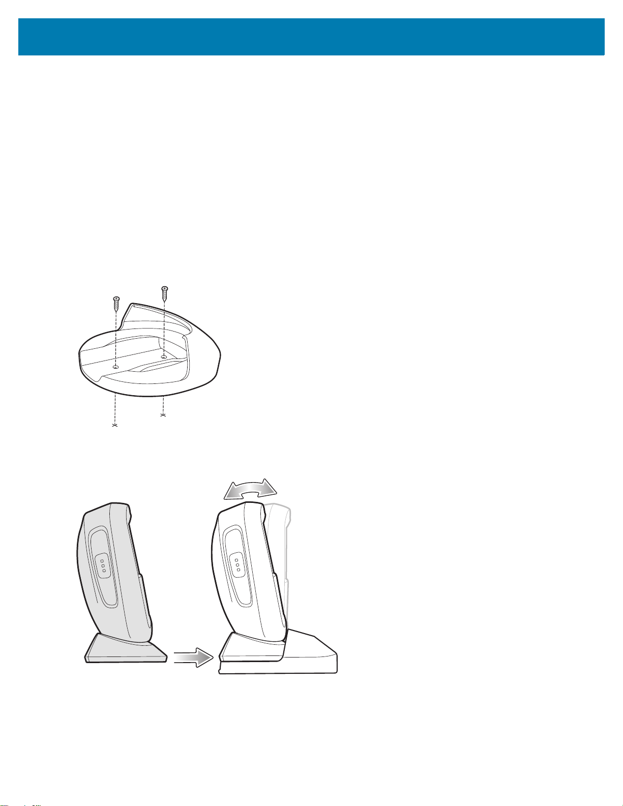
Getting Started
To mount the optional multi-mount bracket using the adhesive pad:
1. Clean the table top surface with Isopropyl alcohol to remove any dirt or debris.
2. Peel the corner of the paper liner off the tape on the bottom of the multi-mount bracket (Figure 5).
3. Press the bottom of the multi-mount bracket on the flat table top and apply uniform pressure for minimally 10
seconds to secure it to the surface (Figure 5).
4. Slide the base of the scanner into the bracket.
Installing Multi-Mount With Screws on Table
To mount the scanner to a table using the optional multi-mount bracket with screws:
1. Place the bracket in the desired location on the table top.
2. Insert two #8 screws through each screw hole in the bracket.
Figure 6 Securing Multi-Mount Bracket to Table
3. Screw into place until secure.
Figure 7 Inserting Scanner into Multi-Mount on Table
4. Slide the base of the scanner into the bracket.
34
Page 35
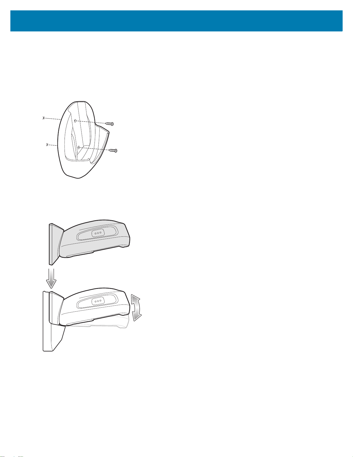
Getting Started
Installing Multi-Mount with Screws on Wall
To mount the scanner on a wall using the optional multi-mount bracket with screws:
1. Place the bracket in its desired location on the wall and insert two #8 screws through each screw hole in the
bracket.
Figure 8 Securing Multi-Mount Bracket to Wall
2. Tighten the screws to secure the bracket to the wall.
3. Slide the base of the scanner into the bracket, oriented so the scan window faces down (Figure 9).
Figure 9 Inserting Scanner into Multi-Mount on Wall
35
Page 36

Getting Started
Locking Table Mount
The optional locking table mount is secured to a flat surface and the scanner is locked into place.
Installing Locking Table Mount
To mount the scanner using the optional locking table mount:
1. Place the bracket in the desired location on the table top and insert two #8 screws through each screw hole in
the bracket.
NOTE: When selecting the desired location to install the locking table mount bracket, be sure to consider that when
the scanner is placed on the mount bracket, it is turned a 1/4 revolution clockwise which will be the final
location the scanner faces.
Figure 10 Installing Locking Table Mount Bracket
2. Place th e sca nn e r on to the br ac ke t.
36
Page 37

Getting Started
Figure 11 Inserting Scanner onto Locking Table Mount Bracket
37
Page 38

Getting Started
3. Turn the scanner 1/4 revolution clockwise until you hear a click and the scanner faces its final position.
Figure 12 Securing Scanner to Locking Mount Bracket
Removing DS9308 from Locking Table Mount
To remove the scanner from the locking table mount, turn counter-clockwise until the scanner is released.
Figure 13 Removing Scanner from Locking Mount Bracket
38
Page 39

123Scan and Software Tools
Introduction
This chapter briefly describes the Zebra software tools available for customizing scanner operation.
123Scan
123Scan is a software tool that simplifies scanner setup and more.
Intuitive enough for first time users, the 123Scan wizard guides users through a streamlined setup process.
Settings are saved in a configuration file that can be printed as a single programming barcode for scanning,
emailed to a smart phone for scanning from its screen, or downloaded to the scanner using a USB cable.
Through 123Scan a user can:
• Configure a scanner using a wizard.
• Program the following scanner settings.
• Beeper tone / volume settings.
• Enable / disable symbologies.
• Communication settings.
• Modify data before transmission to a host using:
• Advanced Data Formatting (ADF) - Scan one barcode per trigger pull.
• Multicode Data Formatting (MDF) - Scan many barcodes in one trigger pull (select scanners).
• Preferred Symbol - Single out one barcode on label of many (select scanners).
• Load parameter settings to a scanner via the following.
• Barcode scanning.
• Scan a paper barcode.
• Scan a barcode from a PC screen.
• Scan a barcode from a smart phone screen.
• Download over a USB cable.
• Load settings to one scanner.
• Stage up to 10 scanners simultaneously (Powered USB Hub recommended with 0.5 amp / port).
39
Page 40

123Scan and Software Tools
• Validate scanner setup.
• View scanned data within the utility's Data view screen.
• Capture an image and save to a PC within the utility's Data view screen.
• Review settings using the Parameter Report.
• Clone settings from an already deployed scanner from the Start screen.
• Upgrade scanner firmware.
• Load settings to one scanner.
• Stage up to 10 scanners simultaneously (Powered USB Hub recommended with 0.5 amp / port).
• View statistics such as:
• Asset tracking information.
• Time and usage information.
• Barcodes scanned by symbology.
• Battery diagnostics (select scanners).
• Generate the following reports.
• Barcode Report - Programming barcode, included parameter settings, and supported scanner models.
• Parameter Report - Parameters programmed within a configuration file.
• Inventory Report - Scanner asset tracking information.
• Validation Report - Scanned data from the Data view.
• Statistics Report - All statistics retrieved from the scanner.
For more information go to: www.zebra.com/123Scan
.
Communication with 123Scan
Use a USB cable to connect the scanner to a Windows host computer running 123Scan.
123Scan Requirements
• Host computer running Windows 7, 8, and 10
• Scanner
• USB cable.
123Scan Information
For more information on123Scan, go to: www.zebra.com/123Scan.
For a 1 minute tour of 123Scan, go to: www.zebra.com/ScannerHowToVideos
To see a list of all of our software tools, go to: www.zebra.com/scannersoftware
.
.
40
Page 41

123Scan and Software Tools
Scanner SDK, Other Software Tools, and Videos
Tackle all your scanner programming needs with our diversified set of software tools. Whether you need to simply
stage a device, or develop a fully featured application with image and data capture as well as asset management,
these tools help you every step of the way.
To download any of the following free tools, go to: www.zebra.com/scannersoftware
• 123Scan configuration utility
• SDKs
• Scanner SDK for Windows
• Scanner SDK for Linux
• Scanner SDK for Android
• Drivers
• OPOS driver
• JPOS driver
• USB CDC driver
• TWAIN driver
• Scanner Management Service (SMS) for Remote Management
• Windows
• Linux
• How-To-Videos
NOTE: For a list of SDK supported scanner functionality by communication protocol, see Communication
Protocol Functionality.
.
41
Page 42

Data Capture
Introduction
This chapter provides beeper and LED definitions, general instructions and tips about scanning, and decode zone
diagrams.
Beeper and LED Indicators
In addition to beep sequences, the scanner uses a two-color LED to indicate status.
• The DS9308 scanner includes one LED indicator for system/decode indications.
Table 3 defines beep sequences that occur during both normal scanning and while programming the scanner; LED
colors that display during scanning.
Table 3 Scanner Beeper and LED Indications
Beeper Sequence LED Indication
Standard Use
Low/medium/high beeps Green Power up.
Medium beep
(or as configured)
None Green (solid) Presentation (Hands-free) Mode on.
None No LED (green LED is
Four long low beeps Red A transmission error occurred. The data is ignored. This
Five long low beeps Red Conversion or format error.
None Red (blinking) on
Image Capture
Low beep Green (blinking) Snapshot mode started.
Hands-free - solid
green LED; turns off
after decode.
Hand-held - LED is off;
green upon decode.
turned off)
trigger pull
A barcode was successfully decoded.
(See User Preferences Parameter Defaults on page 60
for programming beeper sounds.)
Presentation (Hands-free) Mode off.
occurs if a unit is not properly configured. Check option
setting.
Scanner is disabled by a host command to the scanner.
42
Page 43

Data Capture
Table 3 Scanner Beeper and LED Indications (Continued)
Beeper Sequence LED Indication
Low beep Default Green LED
based upon hand-held
or hands-free mode
High/low beeps Default Green LED
based upon hand-held
or hands-free mode
Parameter Programming
Long low/long high beeps Red Input error; incorrect barcode or Cancel scanned, wrong
High/low beeps Green Number expected. Enter value using numeric barcodes.
High/low/high/low beeps Green Successful program exit with change in the parameter
ADF Programming
Low/high/low beeps None ADF transmit error.
High/low beeps Green Number expected. Enter another digit. Add leading zeros
Low/low beeps Green Alphanumeric expected. Enter another alphanumeric
High/high beeps Green blinking ADF criteria or action is expected. Enter another criteria
High/low/low beeps Green All criteria or actions cleared for current rule, continue
High/low/high/low beeps Green
(turns off after blinking)
Long low/long high beeps Red Rule error. Entry error, wrong barcode scanned, or
Low beep Green Deleted last saved rule. The current rule is left intact.
Low/high/high beeps Green All rules deleted.
Long low/long high/long
low/long high beeps
Long low/long high/long
low beeps
Host Specific
USB only
Four high beeps None
RS-232 only
Low/low/low/extra low
beeps
High beep None A <BEL> character is received when Beep on <BEL> is
Red Out of rule memory. Erase some existing rules, then try
Green
(turns off after blinking)
Red RS-232 receive error (parity error).
Snapshot mode completed.
Snapshot mode timed-out.
entry, incorrect barcode programming sequence; remain
in program mode.
setting.
to the front if necessary.
character or scan the End of Message barcode.
or action or scan the Save Rule barcode.
entering rule.
Rule saved. Rule entry mode exited.
criteria/action list is too long for a rule. Re-enter criteria or
action.
to save rule again.
Cancel rule entry. Rule entry mode exited because of an
error or the user asked to exit rule entry.
Scanner has not completed initialization. Wait several
seconds and scan again.
enabled (Point-to-Point mode only).
43
Page 44

Data Capture
Table 3 Scanner Beeper and LED Indications (Continued)
Beeper Sequence LED Indication
123Scan only (When in use, the utility controls the scanner LED)
None Green (slow blinking) Scanner connected to 123Scan.
None Red (fast blinking) File being transferred to the scanner (parameters and
firmware).
None Red (slow blinking) Firmware being activated on the scanner, loaded into
memory.
None Green (solid) Programming completed successfully (parameters and
firmware).
None Red (solid) Error state.
SMS only
None Red (blinking) Loading the SMS package to scanner.
Maintenance Indications
High/high beeps Red (stays on) Enter Bootloader.
None Red (blinking) Firmware installation.
Macro PDF
Low/low beeps None Buffered File ID error. A barcode not in the current MPDF
sequence was scanned.
Long low/long low beeps
(2 long low beeps)
Long low/long low/long
low beeps (3 long low
beeps)
Long low/long low/long
low/long low beeps (4 long
low beeps)
Long low/long low/long
low/long low/long low
beeps (5 long low beeps)
Fast Warble None Aborting MPDF sequence.
Low/high beeps None Flushing an already empty MPDF buffer.
None File ID error. A barcode not in the current MPDF
sequence was scanned.
None Out of memory. There is not enough buffer space to store
the current MPDF symbol.
None Bad symbology. Scanned a 1D or 2D barcode in an
MPDF sequence, a duplicate MPDF label, a label in an
incorrect order, or trying to transmit an empty or illegal
MPDF field.
None Flushing MPDF buffer.
44
Page 45
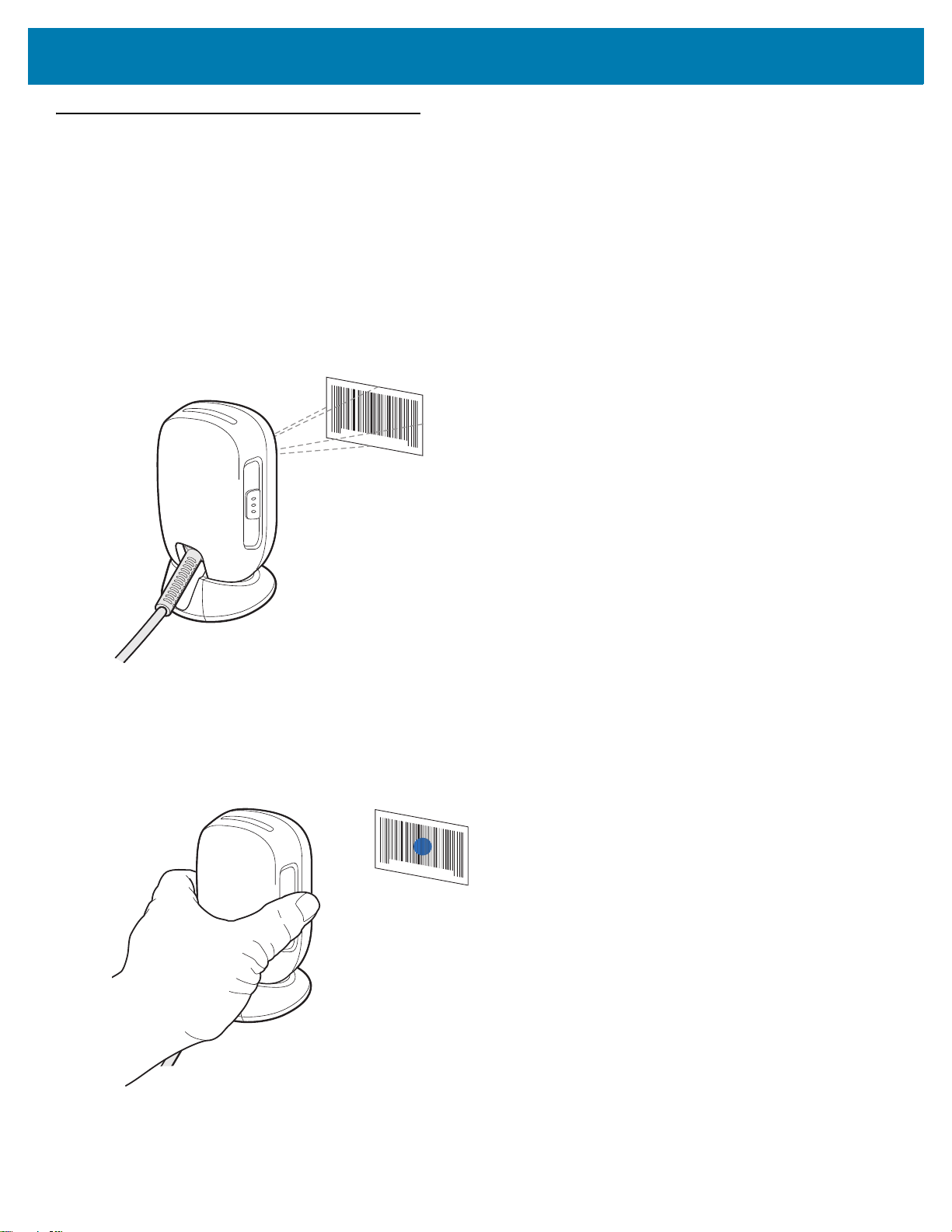
Scanning
Data Capture
The DS9308 has a built-in, adjustable base to easily accommodate both
scanning.
hands-free (presentation)
and hand-held
Hands-free Scanning
The scanner is in
using the multi-mount bracket. In this mode, the scanner operates in continuous (constant-on) mode, where it
automatically decodes a barcode presented in its field of view.
In hands-free mode the LED indicator turns solid green. An aiming dot does not appear.
Figure 14 Scanning in Hands-free Mode
hands-free (presentation) mode
when it sits on a counter top, or when it is mounted on a wall
Hand-held Scanning
To operate the digital scanner in hand-held mode (momentary trigger mode):
1. Pick up the digital scanner and press the trigger. The aiming dot displays.
Figure 15 Scanning in Hand-held (Momentary Trigger) Mode
2. Ensure the aiming dot is centered on the barcode (see Figure 17).
45
Page 46
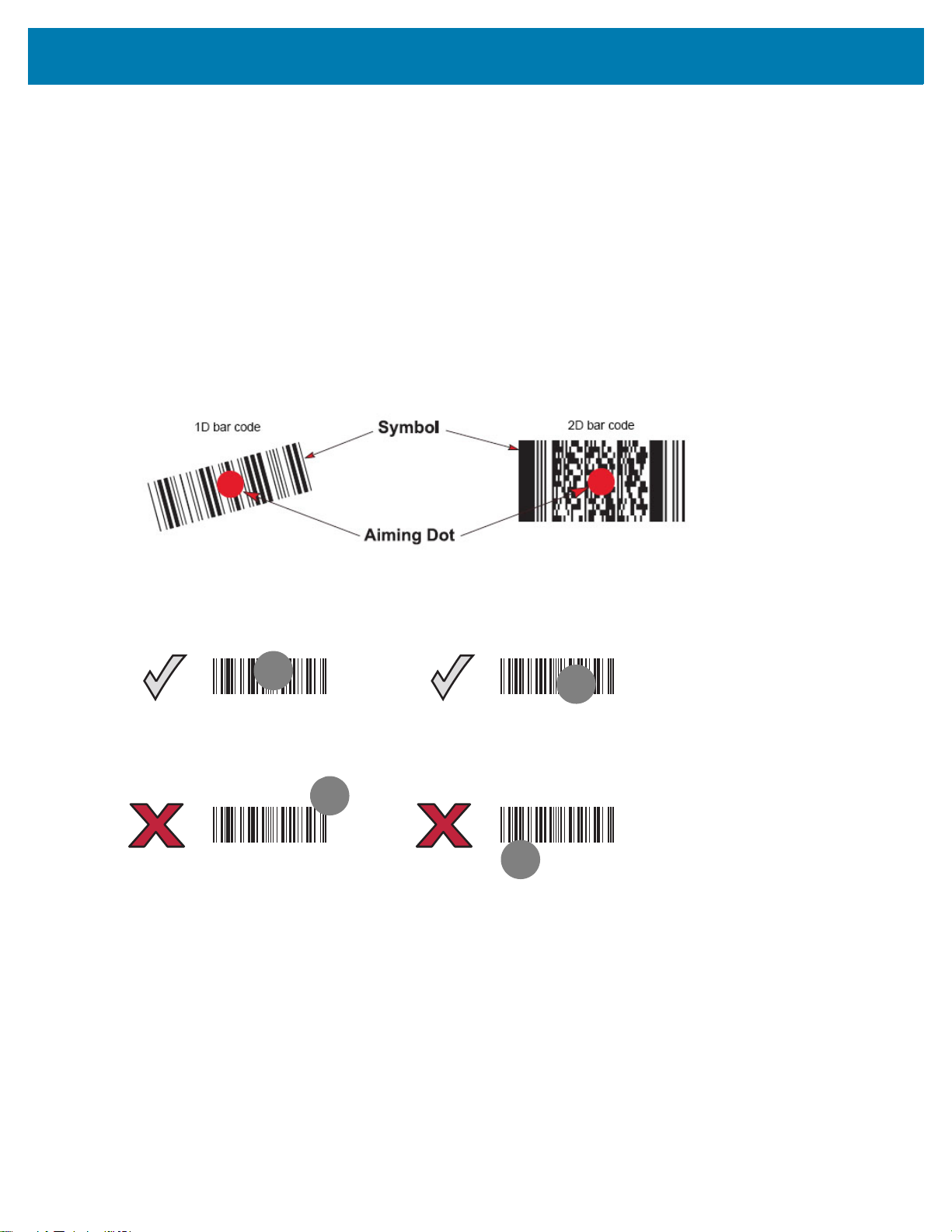
Data Capture
012345
012345
012345
012345
3. Press and hold the trigger until either:
a. The digital scanner reads the barcode. The digital scanner beeps and the successful decode LED flashes.
b. The digital scanner does not read the barcode and the illumination turns off.
4. Release the trigger. The aiming dot reappears. To read another barcode, repeat steps 2 and 3.
After a programmable time period (see Momentary Trigger Mode Timeout on page 77), the aiming dot turns off and
the digital scanner returns to presentation mode, ready to read barcodes without the use of the trigger. For beeper
definitions, see Table 3 on page 42.
Aiming
The scanner may project an LED dot which allows positioning the barcode within its field of view. See Decode
Ranges on page 47 for the proper distance to achieve between the scanner and a barcode.
Figure 16 Scanning Orientation with Imager Aiming Dot
The scanner can also read a barcode presented within the aiming dot not centered. The top examples in Figure 17
show acceptable aiming options, while the bottom examples can not be decoded.
Figure 17 Acceptable and Incorrect Aiming
The aiming dot is smaller when the scanner is closer to the symbol and larger when it is farther from the symbol.
Scan symbols with smaller bars or elements (mil size) closer to the scanner, and those with larger bars or elements
(mil size) farther from the scanner.
The scanner beeps to indicate that it successfully decoded the barcode. For more information on beeper and LED
definitions, see Table 3 on page 42.
46
Page 47

Decode Ranges
Table 4 DS9308 Decode Ranges
Symbol Density Barcode Type Near Far
3.0 mil Code 39 0 in. / 0 cm 2.5 in. / 6.35 cm
4.0 mil Code 39 0 in. / 0 cm 4.0 in. / 10.2 cm
5.0 mil Code 39 0 in. / 0 cm 5.0 in. / 12.7 cm
7.5 mil Code 39 0 in. / 0 cm 6.5 in. / 16.5 cm
20 mil Code 39 0 in. / 0 cm 11.0 in. / 27.9 cm
3 mil Code 128 0 in. / 0 cm 2.0 in. / 5.1 cm
5 mil Code 128 0 in. / 0 cm 4.0 in. / 10.2 cm
13 mil (100%) UPC 0 in. / 0 cm 8.8 in. / 22.4 cm
Data Capture
Working Ranges
10 mil
20 mil
Data Matrix 0 in. / 0 cm 4.5 in. / 11.4 cm
QR 0 in. / 0 cm 7.5 in. / 19.1 cm
Electronic Article Surveillance (EAS)
NOTE: EAS is available only on scanner models that support Checkpoint EAS.
Some scanner configurations include an integrated Electronic Article Surveillance (EAS) antenna.
The scanner's integrated EAS deactivation antenna requires an EAS host cable. This Y-cable connects to the
scanner's host port at one end, and splits to the host and the EAS system at the other end.
Installing
Checkpoint EAS Model Compatibility
The scanner is intended for use with Checkpoint CP-VII, CP-IX, and CP-XI systems. It does not support CP-IV and
other low-power receiver-based EAS deactivation systems.
Considerations
The Checkpoint CP-VII system generates a periodic burst of electromagnetic energy that deactivates EAS tags
brought near the scanner. To avoid interference with the scanner’s operation, take the following precautions when
installing the EAS system:
• Position the EAS antenna box as far as possible from the scanner (at least 6 in. / 15.24 cm.)
• Position the EAS antenna, EAS antenna box, EAS control cable, and EAS controller box as far as possible
from the scanner’s host and power cables.
47
Page 48

Data Capture
EAS range is as dependent on the Checkpoint system (which is calibrated onsite) as it is on the scanner.
Therefore, we cannot provide estimated ranges, however these are some of the factors that contribute to EAS
range:
• Antenna – Length, gauge, number of turns, placement in the scanner.
• Type of Checkpoint EAS system used (ie. CP-VII, CP-IX, and CP-XI).
• Length of wire connecting antenna to (Checkpoint) EAS (site/installation dependent)
• Settings done within Checkpoint system (site/installation dependent).
Checkpoint Contact Information
Contact your local Checkpoint representative to install the EAS cable to the Checkpoint Deactivation System.
48
Page 49

Maintenance, Troubleshooting, and Technical Specifications
Introduction
This chapter provides suggested scanner maintenance, troubleshooting, technical specifications, and signal
descriptions (pinouts).
Maintenance
Known Harmful Ingredients
The following chemicals are known to damage the plastics on Zebra scanners and should not come in contact with
the device:
•Acetone
• Ammonia solutions
• Aqueous or alcoholic alkaline solutions
• Aromatic and chlorinated hydrocarbons
• Benzene
• Carbolic acid
• Compounds of amines or ammonia
• Ethanolamine
• Ethers
• Ketones
•TB-lysoform
• Toluene
• Trichloroethylene.
Approved Cleaners for the Scanner
• Isopropyl alcohol 70% (including pre-moistened wipes).
49
Page 50

Maintenance, Troubleshooting, and Technical Specifications
Cleaning the Scanner
Routinely cleaning the exit window is required. A dirty window may affect scanning accuracy. Do not allow any
abrasive material to touch the window.
To clean the scanner:
1. Dampen a soft cloth with one of the approved cleaning agents listed above or use pre-moistened wipes.
2. Gently wipe all surfaces, including the front, back, sides, top and bottom. Never apply liquid directly to the
scanner. Be careful not to let liquid pool around the scanner window, trigger, cable connector or any other area
on the device.
3. Be sure to clean the trigger and in between the trigger and the housing (use a cotton-tipped applicator to reach
tight or inaccessible areas).
4. Do not spray water or other cleaning liquids directly into the exit window.
5. Wipe the scanner exit window with a lens tissue or other material suitable for cleaning optical material such as
eyeglasses.
6. Immediately dry the scanner window after cleaning with a soft non-abrasive cloth to prevent streaking.
7. Allow the unit to air dry before use.
8. Scanner connectors:
a. Dip the cotton portion of a cotton-tipped applicator in isopropyl alcohol.
b. Rub the cotton portion of the cotton-tipped applicator back-and-forth across the connector on the Zebra
scanner at least 3 times. Do not leave any cotton residue on the connector.
c. Use the cotton-tipped applicator dipped in alcohol to remove any grease and dirt near the connector area.
d. Use a dry cotton tipped applicator and rub the cotton portion of the cotton-tipped applicator back-and-forth
across the connectors at least 3 times. Do not leave any cotton residue on the connectors.
50
Page 51

Maintenance, Troubleshooting, and Technical Specifications
Troubleshooting
NOTE: If after performing the possible solutions in Table 5 the scanner still experiences problems, contact the
distributor or call support.
Table 5 Troubleshooting
Problem Possible Causes Possible Solutions
The illumination does not
appear when pressing the
trigger.
Scanner emits illumination,
but does not decode the
barcode.
No power to the scanner. If the configuration requires a power supply,
re-connect the power supply.
Incorrect host interface cable is
used.
Interface/power cables are loose. Re-connect cables.
Scanner is disabled. For IBM 468x and USB IBM hand-held, IBM
If using RS-232 Nixdorf B mode,
CTS is not asserted.
Illumination is disabled. Enable the illumination. See Decoding
Scanner is not programmed for
the correct barcode type.
Barcode symbol is unreadable. Scan test symbols of the same barcode type
The symbol is not completely
inside illumination.
Connect the correct host interface cable.
table-top, and OPOS modes, enable the
scanner via the host interface. Otherwise,
see the technical person in charge of
scanning.
Assert CTS line.
Illumination on page 84.
Program the scanner to read that type of
barcode. See Symbologies.
to determine if the barcode is defaced.
Move the symbol completely within the
illumination.
Move the symbol completely within the field
of view (AIM pattern does NOT define FOV)
Distance between scanner and
barcode is incorrect.
51
Move the scanner closer to or further from
the barcode. See Decode Ranges on page
47.
Page 52

Maintenance, Troubleshooting, and Technical Specifications
Table 5 Troubleshooting (Continued)
Problem Possible Causes Possible Solutions
Scanner decodes barcode,
but does not transmit the
data to the host.
Host displays scanned
data incorrectly.
Scanner is not programmed for
the correct host type.
Interface cable is loose. Re-connect the cable.
If the scanner emits four long low
beeps, a transmission error
occurred.
This occurs if a unit is not properly
configured or connected to the
wrong host type.
If the scanner emits 5 low beeps,
a conversion or format error
occurred.
If the scanner emits low/high/low
beeps, it detected an invalid ADF
rule.
Scanner is not programmed to
work with the host.
Scan the appropriate host type programming
barcode. See the chapter corresponding to
the host type.
Set the scanner's communication parameters
to match the host's setting.
Configure the scanner's conversion
parameters properly.
Program the correct ADF rules. Refer to the
Advanced Data Formatting Programmer
Guide.
Scan the appropriate host type programming
barcode.
For RS-232, set the scanner's
communication parameters to match the
host's settings.
Scanner emits short
low/short medium/short
high beep sequence
(power-up beep sequence)
more than once.
Scanner emits 4 short high
beeps during decode
attempt.
Scanner emits
Low/low/low/extra low
beeps when not in use.
Scanner emits low/high
beeps during
programming.
For a Keyboard Wedge configuration,
program the system for the correct keyboard
type, and turn off the CAPS LOCK key.
Program the proper editing options (e.g.,
UPC-E to UPC-A Conversion).
The USB bus may put the
scanner in a state where power to
the scanner is cycled on and off
more than once.
Scanner has not completed USB
initialization.
RS-232 receive error. Normal during host reset. Otherwise, set the
Input error, incorrect barcode or
Cancel barcode was scanned.
Normal during host reset.
Wait several seconds and scan again.
scanner's RS-232 parity to match the host
setting.
Scan the correct numeric barcodes within
range for the parameter programmed.
52
Page 53

Maintenance, Troubleshooting, and Technical Specifications
Table 5 Troubleshooting (Continued)
Problem Possible Causes Possible Solutions
Scanner emits
low/high/low/high beeps
during programming.
Scanner emits low/high/low
beeps.
Scanner emits a power-up
beep after changing USB
host type.
Scanner emits one high
beep when not in use.
Scanner emits frequent
beeps.
Out of host parameter storage
space.
Out of memory for ADF rules. Reduce the number of ADF rules or the
During programming, indicates
out of ADF parameter storage
space.
ADF transmit error. Refer to the Advanced Data Formatting
Invalid ADF rule is detected. Refer to the Advanced Data Formatting
The USB bus re-established
power to the scanner.
In RS-232 mode, a <BEL>
character was received and Beep
on <BEL> option is enabled.
Inadequate power supplied to the
scanner.
Scan Default Parameters on page 62.
number of steps in the ADF rules.
Erase all rules and re-program with shorter
rules.
Guide for information.
Guide for information.
Normal when changing USB host type.
Normal when Beep on <BEL> is enabled
and the scanner is in RS-232 mode.
Check the system power. If the configuration
requires a power supply, re-connect the
power supply.
Scanner emits five long low
beeps after a barcode is
decoded.
Incorrect host interface cable is
used.
Interface/power cables are loose. Check for loose cable connections and
Conversion or format error was
detected.
The scanner conversion
parameters are not properly
configured.
Conversion or format error was
detected.
An ADF rule was set up with
characters that can't be sent for
the host selected.
Conversion or format error was
detected.
A barcode was scanned with
characters that can't be sent for
that host.
Verify that the correct host interface cable is
used. If not, connect the correct host
interface cable.
re-connect cables.
Ensure the scanner conversion parameters
are properly configured.
Change the ADF rule, or change to a host
that can support the ADF rule.
Change the barcode, or change to a host that
can support the barcode.
53
Page 54

Maintenance, Troubleshooting, and Technical Specifications
Report Product Information
Report Software Version
Scan the following barcode to send the version of software installed in the scanner.
Report Software Version
Report Serial Number
Scan the following barcode to send the scanner serial number to the host.
Serial Number
Report Manufacturing Information
Scan the following barcode to send the scanner manufacturing information to the host.
Manufacturing Information
54
Page 55

Maintenance, Troubleshooting, and Technical Specifications
Technical Specifications
Table 6 Technical Specifications
Item Description
Physical Characteristics
Dimensions
Weight
Available Colors Midnight Black, Alpine White
Supported Host Interfaces USB, RS232, Keyboard Wedge, TGCS (IBM) 46XX over RS485
USB Certification DS9308 is USB2.0 Full Speed Compliant, visit USB.org
Keyboard Support Supports over 90 international keyboards
Electronic Article Surveillance Compatible with Checkpoint deactivation system
Electrical Characteristics
Supply Voltage 4.5 5.0 5.5 V
Idle current (Hand-held) 75 mA
5.7 in H x 3.4 in W x 3.3 in D
14.5 cm H x 8.6 cm W x 8.3 cm D
11.2 oz (318 g)
for more
details.
SR and DL Models
Minimum Maximum Unit
Idle current (Hands-free) 135 mA
Scanning current (Hand-held) 350 mA
Scanning current (Hands-free) 335 mA
Performance Characteristics
Swipe Speed
Aiming Dot
Illumination
Field of View
(Horizontal x Vertical) Nominal
Up to 120 in./305 cm per second for 13 mil UPC in optimized
mode
Amber 617nm LED
Red 660nm LED
52° H x 33° V
55
Page 56

Maintenance, Troubleshooting, and Technical Specifications
Table 6 Technical Specifications (Continued)
Item Description
Image Sensor 1280 x 800 pixels
Minimum Print Contrast 15% minimum reflective difference
Skew Tolerance +/- 60°
Pitch Tolerance +/- 60°
Roll Tolerance 360°
Image Capture
Graphics Format Support Images can be exported as Bitmap, JPEG, or TIFF
Resolution (4 x 5.8 in. document @ 6 in.) 109 PPI
User Environment
Operating Temperature 32º F to 122º F (0º C to 50º C)
Storage Temperature -40° to 158°F / -40° to 70°C
Humidity 5% to 95% RH, non-condensing
Drop Specifications Designed to withstand multiple drops at 5.0 ft/1.5 m to concrete
Tumble Specification (Scanner) Designed to withstand 1,000 tumbles in 1.5 ft./0.5 m tumbler
Ambient Light Immunity 0 to 10,000 Foot Candles/0 to 107,700 Lux
Environmental Sealing IP52
Electrostatic Discharge (ESD) ESD per EN61000-4-2, +/-15 KV Air, +/-8 KV Indirect
Accessories (see page 24)
Symbol Decode Capability
1D Code 39, Code 128, Code 93, Codabar/NW7, Code 11, MSI
Plessey, UPC/EAN, I 2 of 5, Korean 3 of 5, GS1 DataBar, Base
32 (Italian Pharma)
2D PDF417, Micro PDF417, Composite Codes, TLC-39, Aztec,
Data Matrix, MaxiCode, QR Code, Micro QR, Han Xin, Postal
Codes, SecurPharm, Dotcode, Dotted Datamatrix
Digimarc Digital watermark technology; available on specific models only
OCR OCR-A, OCR-B, MICR, US Currency
Minimum Element Resolution Code 39 3 mil
Code 128 3 mil
QR Code 5 mil
Data Matrix 5 mil
Regulatory
See Decode Ranges on page 47 for working ranges.
56
Page 57

Maintenance, Troubleshooting, and Technical Specifications
Table 6 Technical Specifications (Continued)
Item Description
Environmental: Restriction of Hazardous
Substances (RoHS)
EMC EN 55032, EN55024, EN55035
Health and Safety IEC 62368-1, UL 62368-1, CAN/CSA-22.2 N0. 62368-1-14
Utilities and Management
123Scan Programs scanner parameters, upgrades firmware, provides
Symbol Scanner SDK Generates a fully-featured scanner application, including
Scanner Management Service (SMS) Remotely manages your Zebra scanner and queries its asset
EN 50581
EN IEC 63000
EN 61000-3-2, EN 61000-3-3
47 CFR Part 15, Subpart B, Class B, ICES-003, Class B
IEC 62471
scanned barcode data and prints reports. See 123Scan and
Software Tools.
www.zebra.com/123Scan
documentation, drivers, test utilities and sample source code.
www.zebra.com/ScannerSDKforWindows
information.
www.zebra.com/sms
57
Page 58

Maintenance, Troubleshooting, and Technical Specifications
Cable Interface Port
PIN 10
PIN 1
Interface Cable
Modular Connector
Scanner Signal Descriptions
Figure 18 Scanner Cable Pinouts
The signal descriptions in Table 7 apply to the connectors on the DS9308 scanner and are for reference only.
Table 7 DS9308 Scanner Signal Pin-outs
Note: EAS configurations use pins 9 and 10 for an EAS antenna. For other configurations pins 9 and 10
are open.
Pin IBM RS-232 Keyboard Wedge USB
1 Cable ID Cable ID Cable ID Cable ID
2 Power (+5V) Power (+5V) Power (+5V) Power (+5V)
3 Ground Ground Ground Ground
4 IBM_OUT TxD KeyClock Reserved
5 IBM_IN RxD TermData D +
6 IBM_T/R RTS KeyData Reserved
7 Reserved CTS TermClock D -
8 Reserved Reserved Reserved Reserved
9 See note
10 See note
58
Page 59

User Preferences &
* Enable Parameter
(1)
Feature/option
* Indicates default
Option value
Miscellaneous Options
Introduction
You can program the scanner to perform various functions, or activate different features. This chapter describes
user preference features and provides programming barcodes for selecting these features.
The scanner ships with the settings shown in Table 8 on page 60 (also see Parameter Defaults for all defaults). If
the default values suit requirements, programming is not necessary.
Setting Parameters
To set feature values, scan a single barcode or a short barcode sequence. The settings are stored in non-volatile
memory and are preserved even when the scanner powers down.
NOTE: Most computer monitors allow scanning barcodes directly on the screen. When scanning from the screen,
be sure to set the document magnification to a level where you can see the barcode clearly, and bars and/or
spaces do not merge.
If not using the default host, select the host type (see each host chapter for specific host information) after the
power-up beeps sound. This is only necessary upon the first power-up when connected to a new host.
To return all features to default values, see Default Parameters on page 62. Throughout the programming barcode
menus, asterisks indicate (
*) default values.
Scanning Sequence Examples
In most cases, scanning one barcode sets the parameter value. For example, to set the beeper tone to high, scan
the High Frequency (beep tone) barcode listed under Beep Tone on page 65. The scanner issues a fast warble
beep and the LED turns green, signifying a successful parameter entry.
Other parameters require scanning several barcodes. See the parameter descriptions for this procedure.
59
Page 60
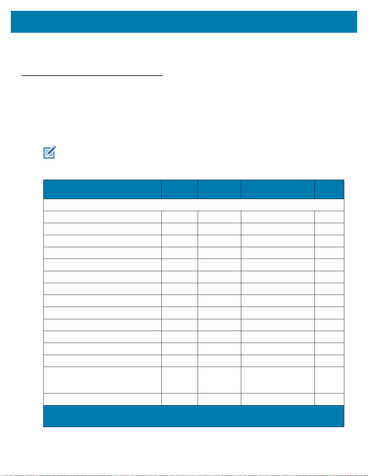
User Preferences & Miscellaneous Options
Errors While Scanning
Unless otherwise specified, to correct an error during a scanning sequence, just re-scan the correct parameter.
User Preferences/Miscellaneous Options Parameter Defaults
Table 8 lists defaults for user preferences parameters. Change these values in one of two ways:
• Scan the appropriate barcodes in this chapter. The new value replaces the standard default value in
memory. To recall default parameter values, see Default Parameters on page 62.
• Configure the scanner using the 123Scan
NOTE: See Parameter Defaults for all user preference, host, symbology, and miscellaneous default parameters.
Table 8 User Preferences Parameter Defaults
configuration program. See 123Scan and Software Tools.
Parameter
Standard User Preferences
Set Default Parameter N/A N/A N/A 62
Parameter Barcode Scanning 236 ECh Enable 63
Beep After Good Decode 56 38h Enable 63
Beep Volume 140 8Ch High 64
Beep Tone 145 91h Medium 65
Beep Duration 628 F1h 74h Short 67
Volume Adjustment Trigger Timeout 403 F0h 93h 5 Seconds 68
Suppress Power Up Beeps 721 F1h D1h Do Not Suppress 69
Direct Decode Indicator 859 F2h 5Bh Disable 70
Low Power Mode 128 80h Disable 71
Time Delay to Low Power Mode 146 92h 1 Hour 72
Trigger Mode 138 8Ah Presentation Mode 74
Parameter
Number
1
SSI
Number
2
Default
Number
Page
Hand-held Decode Aiming Pattern 306 F0h 32h Enable 75
Presentation (Hands-free) Decode Aiming
Pattern
Momentary Trigger Mode Timeout 2030 EDh 5 Seconds 77
1. Parameter number decimal values are used for programming via RSM commands.
2. SSI number hex values are used for programming via SSI commands.
590 F1h 4Eh Disable Presentation
(Hands-free) Decode
Aiming Pattern
76
60
Page 61

User Preferences & Miscellaneous Options
Table 8 User Preferences Parameter Defaults (Continued)
Parameter
Picklist Mode 402 F0h 92h Enable Picklist Mode in
Continuous Barcode Read 649 F1h 89h Disable 79
Unique Barcode Reporting 723 F1h D3h Enable 79
Decode Session Timeout 136 88h 9.9 Seconds 80
Timeout Between Decodes, Same
Symbol
Timeout Between Decodes, Different
Symbols
Triggered Timeout, Same Symbol 724 F1h D4h Disable 81
Mobile Phone/Display Mode 716 F1h CCh Normal 82
PDF Prioritization 719 F1h CFh Disable 83
PDF Prioritization Timeout 720 F1h D0h 200 ms 83
Decoding Illumination 298 F0h 2Ah Enable 84
Illumination Brightness 669 F1h 9Dh High 84
Parameter
Number
137 89h 0.5 Seconds 80
144 90h 0.1 Seconds 81
1
SSI
Number
2
Hand-held Mode
Default
Number
78
Page
Motion Tolerance (Hand-held Trigger
Mode Only)
Product ID (PID) Type 1281 F8h 05h 01h Host Type Unique 86
Product ID (PID) Value 1725 F8h 06h BDh 0 87
ECLevel 1710 F8h 06h AEh 0
Miscellaneous Options
Enter Key N/A N/A N/A 88
Tab Key N/A N/A N/A 88
Transmit Code ID Character 45 2Dh None 89
Prefix Value 99, 105 63h, 69h 7013 <CR><LF> 90
Suffix 1 Value
Suffix 2 Value
Scan Data Transmission Format 235 EBh Data As Is 91
FN1 Substitution Values 103, 109 67h, 6Dh 7013 <CR><LF> 93
Transmit “No Read” Message 94 5E Disable 94
Unsolicited Heartbeat Interval 1118 F8h 04h 5Eh Disable 95
858 F2h 5Ah Less Motion Tolerance 86
87
98, 104
100, 106
62h, 68h
64h, 6Ah
7013 <CR><LF> 90
1. Parameter number decimal values are used for programming via RSM commands.
2. SSI number hex values are used for programming via SSI commands.
61
Page 62

User Preferences & Miscellaneous Options
Table 8 User Preferences Parameter Defaults (Continued)
Parameter
securPharm Decoding 1752 F8h 06h D8h Disable 96
securPharm Output Formatting 1753 F8h 06h D9h No Formatting 97
1. Parameter number decimal values are used for programming via RSM commands.
2. SSI number hex values are used for programming via SSI commands.
Standard User Preferences
Default Parameters
Scan one of the following barcodes to reset the scanner to its default settings as follows:
• Restore Defaults resets all default parameters as follows:
• If you configured custom default parameter values via the Write to Custom Defaults barcode,
scanning the Restore Defaults barcode restores these custom values.
• If you did not configure custom default parameter values, scanning the Restore Defaults barcode
restores the factory default values. See Parameter Defaults for these values.
• Set Factory Defaults clears all custom default values and sets the factory default values. See Parameter
Defaults for these values.
Parameter
Number
1
SSI
Number
2
Default
Page
Number
Write to Custom Defaults
To create a set of custom defaults, select the desired parameter values in this guide, and then scan Write to
Custom Defaults.
Restore Defaults
Set Factory Defaults
Write to Custom Defaults
62
Page 63

User Preferences & Miscellaneous Options
Parameter Barcode Scanning
Parameter # 236
SSI # ECh
Scan one of the following barcodes to select whether to enable or disable the decoding of parameter barcodes,
including the Set Defaults barcodes.
* Enable Parameter Barcode Scanning
(1)
Disable Parameter Barcode Scanning
(0)
Beep After Good Decode
Parameter # 56
SSI # 38h
Scan one of the following barcodes to select whether or not the scanner beeps after a good decode.
If you select Do Not Beep After Good Decode, the beeper still operates during parameter menu scanning and to
indicate error conditions.
* Enable Beep After Good Decode
(1)
63
Disable Beep After Good Decode
(0)
Page 64

User Preferences & Miscellaneous Options
Beep Volume
Parameter # 140
SSI # 8Ch
Scan one of the following barcodes to select a beep volume.
Low Volume
(2)
Medium Volume
(1)
* High Volume
(0)
64
Page 65

User Preferences & Miscellaneous Options
Beep Tone
Parameter # 145
SSI # 91h
Scan one of the following barcodes to select a beep tone for audible feedback indicating a good decode. Select
from the Standard Beep Tones below or from the Beep Duration on page 67.
Scan Disable Beep Tone to disable all tones.
Disable Beep Tone
(3)
Standard Beep Tones
* Medium Beep Tone
(1)
Medium to High Beep Tone (2-tone)
(4)
Low Beep Tone
(2)
High Beep Tone
(0)
65
Page 66

Special Tones
Wood Block / Tone 1
Chime / Tone 3
User Preferences & Miscellaneous Options
(6)
Pulse / Tone 2
(7)
(8)
Triple Beep / Tone 5
(10)
Zap / Tone 4
(9)
User Programmable / Tone 6
(11)
Note: See Custom Tone to download a custom tone.
66
Page 67

User Preferences & Miscellaneous Options
Beep Duration
Parameter # 628
SSI # F1h 74h
Scan one of the following barcodes to select the duration for the good decode beep.
* Short Duration
(0)
Medium Duration
(1)
Long Duration
(2)
67
Page 68

User Preferences & Miscellaneous Options
Volume Adjustment Trigger Timeout
Parameter # 403
SSI # F0h 93h
Scan one of the following barcodes to set the length of time needed to hold the trigger to adjust the volume.
The scanner changes volume and beeps with the new volume.
3 Seconds
(30)
7 Seconds
(70)
* 5 Seconds
(50)
10 Seconds
(100)
68
Page 69

User Preferences & Miscellaneous Options
Suppress Power Up Beeps
Parameter # 721
SSI # F1h D1h
Scan one of the following barcodes to select whether or not to suppress the scanner’s power-up beeps.
* Do Not Suppress Power Up Beeps
(0)
Suppress Power Up Beeps
(1)
69
Page 70

User Preferences & Miscellaneous Options
Direct Decode Indicator
Parameter # 859
SSI # F2h 5Bh
This parameter is only supported in Standard (Level) Trigger Mode. Scan one of the following barcodes to select
optional blinking of the illumination on a successful decode if you continue to hold the trigger. If you release the
trigger upon decode, the blinking does not occur. This allows you to choose additional feedback for a successful
decode by holding the trigger, or to continue to scan as normal.
• * Disable Direct Decode Indicator - Illumination does not blink on a successful decode.
• 1 Blink - Illumination blinks once upon a successful decode.
• 2 Blinks - Illumination blinks twice upon a successful decode.
* Disable Direct Decode Indicator
(0)
2 Blinks
(2)
1 Blink
(1)
70
Page 71

User Preferences & Miscellaneous Options
Low Power Mode
Parameter # 128
SSI # 80h
NOTE: The Low Power Mode parameter only applies for non-USB and non-RS485 host interfaces, and when
Trigger Mode is set to Level (Standard).
Scan one of the following barcodes to select whether or not the scanner enters low power mode after a decode
attempt or host communication. This applies to serial and keyboard wedge connections. If disabled, power
remains on after each decode attempt.
If you enable this, see Time Delay to Low Power Mode to set the inactivity time period.
Enable Low Power Mode
(1)
* Disable Low Power Mode
(0)
71
Page 72

User Preferences & Miscellaneous Options
Time Delay to Low Power Mode
Parameter # 146
SSI # 92h
NOTE: This parameter only applies when Low Power Mode is enabled.
Scan one of the following barcodes to set the time the scanner remains active before entering low power mode.
The scanner wakes upon trigger press or when the host attempts to communicate with the scanner.
1 Second
(17)
1 Minute
(33)
15 Minutes
(43)
10 Seconds
(26)
5 Minutes
(37)
72
Page 73

User Preferences & Miscellaneous Options
Time Delay to Low Power Mode (continued)
30 Minutes
(45)
45 Minutes
(46)
* 1 Hour
(49)
6 Hours
(54)
3 Hours
(51)
73
9 Hours
(57)
Page 74

User Preferences & Miscellaneous Options
Trigger Mode
Parameter # 138
SSI # 8Ah
Scan one of the following barcodes to select a trigger mode for the scanner:
• Standard (Level) - A trigger press activates decode processing. Decode processing continues until the
barcode decodes, you release the trigger, or the Decode Session Timeout on page 80 occurs.
• * Presentation (Blink) - The scanner activates decode processing when it detects a barcode in its field of
view. After a period of non-use, the LEDs turn off until the scanner senses motion..
Standard (Level)
(0)
* Presentation (Blink)
(7)
74
Page 75

User Preferences & Miscellaneous Options
Hand-held Decode Aiming Pattern
Parameter # 306
SSI # F0h 32h
NOTE: The decode aiming pattern flashes even if you disable the Hand-held Decode Aiming Pattern if the trigger
button is pressed.
Scan one of the following barcodes to select when to project the aiming pattern in hand-held mode:
• Enable Hand-held Decode Aiming Pattern - This projects the aiming pattern during barcode capture.
• Disable Hand-held Decode Aiming Pattern - This turns the aiming pattern off.
• Enable Hand-held Decode Aiming Pattern on PDF - This projects the aiming pattern when the scanner
detects a PDF barcode.
* Enable Hand-held Decode Aiming Pattern
(2)
Enable Hand-held Decode Aiming Pattern on PDF
(3)
Disable Hand-held Decode Aiming Pattern
(0)
75
Page 76
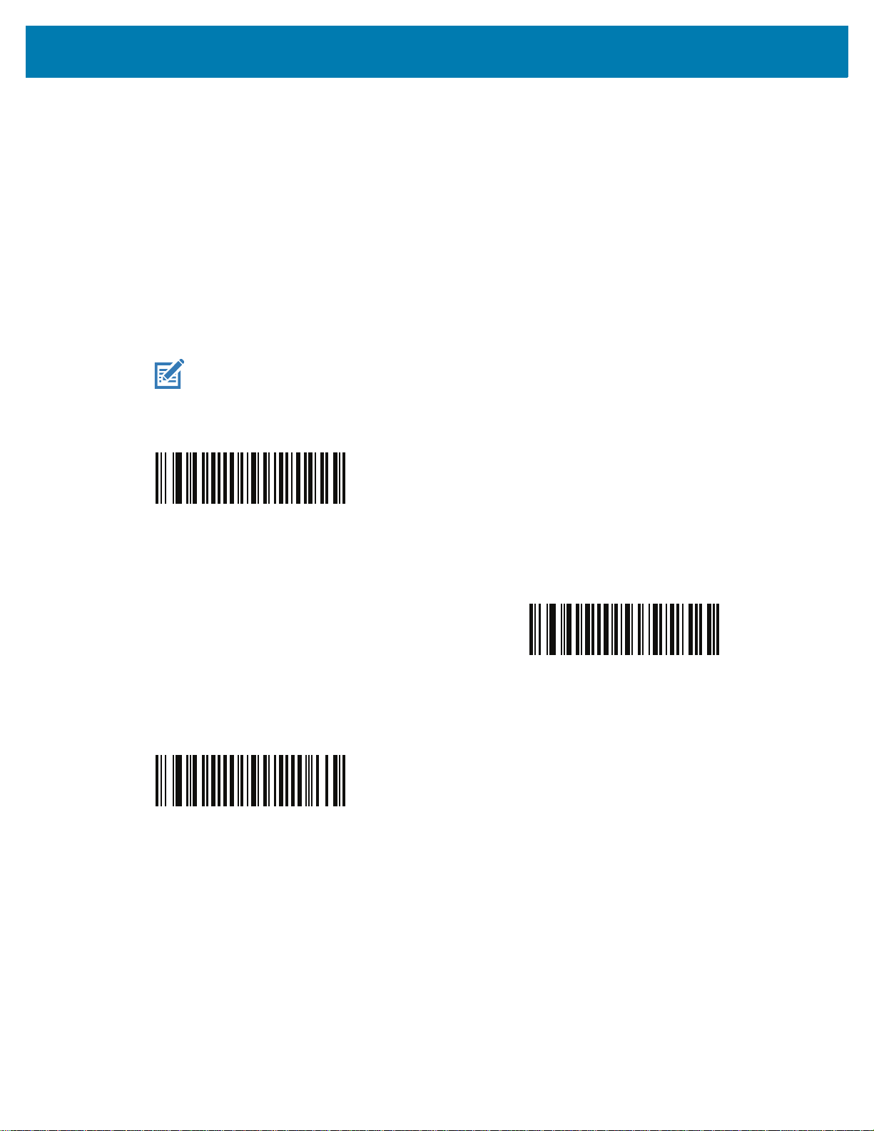
User Preferences & Miscellaneous Options
Presentation (Hands-free) Decode Aiming Pattern
Parameter # 590
SSI # F1h 4Eh
Scan one of the following barcodes to select when to project the aiming pattern in hands-free mode:
• Enable Presentation (Hands-free) Decode Aiming Pattern - This projects the aiming pattern during
barcode capture.
• Disable Presentation (Hands-free) Decode Aiming Pattern - This turns the aiming pattern off.
• Enable Presentation (Hands-free) Decode Aiming Pattern on PDF - This projects the aiming pattern
when the scanner detects a PDF barcode.
NOTE: With Momentary Trigger Mode Timeout on page 77 enabled, the decode aiming pattern flashes
even when you disable the Hands-free Decode Aiming Pattern.
Enable Presentation (Hands-free)
Decode Aiming Pattern
(1)
Enable Presentation (Hands-free)
Decode Aiming Pattern on PDF
(2)
* Disable Presentation (Hands-free)
Decode Aiming Pattern
(0)
76
Page 77

User Preferences & Miscellaneous Options
Momentary Trigger Mode Timeout
Parameter # 2030
SSI # EDh
In momentary trigger mode, the aiming pattern appears upon pressing the trigger. Once in this mode, upon each
trigger press the scanner attempts to decode the barcode in front of it. After a period of inactivity while the trigger is
not pressed, the scanner reverts to presentation mode where there is no illumination until an item is presented.
Scan one of the following barcodes to set the length of the period of inactivity in momentary trigger mode before
the scanner reverts to presentation mode.
2 Seconds
(20)
4 Seconds
(40)
3 Seconds
(30)
* 5 Seconds
(50)
77
Page 78

User Preferences & Miscellaneous Options
Picklist Mode
Parameter # 402
SSI # F0h 92h
Scan one of the following barcodes to select a Picklist Mode. In this mode, you can pick out and decode a barcode
from a group of barcodes that are printed close together by placing the aiming pattern on the barcode you want to
decode.
NOTES: Enabling Picklist Mode overrides the Disable Decode Aiming Pattern options. You can not disable the
decode aiming pattern when Picklist Mode is enabled.
Enabling Picklist Mode can slow decode speed and hinder the ability to decode longer barcodes.
• Enable Picklist Mode Always - Picklist Mode is always enabled.
• Enable Picklist Mode in Hand-held Mode - Picklist Mode is enabled when the scanner is out of
hands-free mode and disabled when the scanner is in presentation mode.
• Enable Picklist Mode in Hands-free Mode - Picklist Mode is enabled when the scanner is in hands-free
mode only.
NOTE: When using Picklist Mode in Hands-free Mode, increase the time of the Timeout Between Decodes,
Same Symbol on page 80.
• Disable Picklist Mode Always - Picklist Mode is always disabled.
Enable Picklist Mode Always
(2)
* Enable Picklist Mode in Hand-held Mode
Enable Picklist Mode in Hands-free Mode
(3)
(1)
78
Disable Picklist Mode Always
(0)
Page 79

User Preferences & Miscellaneous Options
Continuous Barcode Read
Parameter # 649
SSI # F1h 89h
Scan Enable Continuous Barcode Read to report every barcode while the trigger is pressed.
NOTE: We strongly recommend enabling Momentary Trigger Mode Timeout on page 77 with this parameter.
Disabling Picklist Mode can cause accidental decodes when more than one barcode is in the scanner's
field of view.
Enable Continuous Barcode Read
(1)
* Disable Continuous Barcode Read
(0)
Unique Barcode Reporting
Parameter # 723
SSI # F1h D3h
Scan Enable Continuous Barcode Read Uniqueness to report only unique barcodes while the trigger is
pressed. This option only applies when Continuous Barcode Read is enabled.
* Enable Unique Barcode Reporting
(1)
79
Disable Unique Barcode Reporting
(0)
Page 80

User Preferences & Miscellaneous Options
Decode Session Timeout
Parameter # 136
SSI # 88h
This parameter sets the maximum time decode processing continues during a scan attempt. It is programmable in
0.1 second increments from 0.5 to 9.9 seconds. The default timeout is 9.9 seconds.
To set a Decode Session Timeout, scan the following barcode, and then scan two barcodes from Numeric
Barcodes that correspond to the desired on time. Enter a leading zero for single digit numbers. For example, to set
a Decode Session Timeout of 0.5 seconds, scan this barcode, and then scan the 0 and 5 barcodes. To correct an
error or change the selection, scan Cancel
Decode Session Timeout
.
Timeout Between Decodes, Same Symbol
Parameter # 137
SSI # 89h
Use this option in presentation mode or Continuous Barcode Read mode to prevent the scanner from continuously
decoding the same barcode when it is left in the scanner’s field of view. The barcode must be out of the field of
view for the timeout period before the scanner reads the same consecutive symbol. It is programmable in 0.1
second increments from 0.0 to 9.9 seconds. The default interval is 0.5 seconds.
To select the timeout between decodes for the same symbol, scan the following barcode, and then scan two
barcodes from Numeric Barcodes that correspond to the desired interval, in 0.1 second increments.
Timeout Between Decodes, Same Symbol
80
Page 81

User Preferences & Miscellaneous Options
Timeout Between Decodes, Different Symbols
Parameter # 144
SSI # 90h
Use this option in presentation mode or Continuous Barcode Read to control the time the scanner waits before
decoding a different symbol. It is programmable in 0.1 second increments from 0.1 to 9.9 seconds. The default is
0.1 seconds.
To select the timeout between decodes for different symbols, scan the following barcode, and then scan two
barcodes from Numeric Barcodes that correspond to the desired interval, in 0.1 second increments.
NOTE: Timeout Between Decodes, Different Symbols cannot be greater than or equal to the Decode Session
Timeout.
Timeout Between Decodes, Different Symbols
Triggered Timeout, Same Symbol
Parameter # 724 (SSI # F1h D4h)
NOTE: This feature does not apply to Timeout Between Decodes, Different Symbols.
NOTE: Timeout Between Decodes, Same Symbol cannot be greater than or equal to the Time Delay to Low
Power Mode (parameter #146 on page
Scan Enable Triggered Timeout, Same Symbol below to apply Timeout Between Decodes, Same Symbol
(parameter #137 on page 80) in hand-held trigger mode. Subsequent scans of Enable Triggered Timeout, Same
Symbol are ignored until Timeout Between Decodes, Same Symbol expires.
Enable Triggered Timeout, Same Symbol
(1)
72).
* Disable Triggered Timeout, Same Symbol
(0)
81
Page 82

User Preferences & Miscellaneous Options
Mobile Phone/Display Mode
Parameter # 716
SSI # F1h CCh
This mode improves barcode reading performance off mobile phones and electronic displays. Scan one of the
following barcodes to select the desired mode.
* Normal Mobile Phone/Display Mode
(0)
Enhanced in Hands-free Mode
(2)
Enhanced in Hand-held Mode
(1)
Enhanced in Both Modes
(3)
82
Page 83

PDF Prioritization
Parameter # 719
SSI # F1h CFh
User Preferences & Miscellaneous Options
Scan Enable PDF Prioritization to delay decoding certain 1D barcodes (see
PDF Prioritization Timeout. During that time the scanner attempts to decode a PDF417 symbol (e.g., on a US
driver's license), and if successful, reports this only. If it does not decode (can not find) a PDF417 symbol, it reports
the 1D symbol after the timeout. The 1D symbol must be in the device’s field of view for the scanner to report it.
This parameter does not affect decoding other symbologies.
NOTE: To use PDF Prioritization in hand-held mode, you must disable Picklist Mode.
NOTE: The 1D Code 128 barcode lengths include the following:
• 7 to 10 characters
• 14 to 22 characters
• 27 to 28 characters
In addition, a Code 39 barcode with the following lengths are considered to potentially be part of a US
driver’s license:
• 8 characters
• 12 characters
Note
below) by the value specified in
Enable PDF Prioritization
(1)
* Disable PDF Prioritization
(0)
PDF Prioritization Timeout
Parameter # 720
SSI # F1h D0h
If you enabled PDF Prioritization, set this timeout to indicate how long the scanner attempts to decode a PDF417
symbol before reporting the 1D barcode in the field of view.
83
Page 84

User Preferences & Miscellaneous Options
Scan the following barcode, and then scan four barcodes from Numeric Barcodes that specify the timeout in
milliseconds. For example, to enter 400 ms, scan the following barcode, and then scan 0400. The range is 0 to
5000 ms, and the default is 200 ms.
PDF Prioritization Timeout
Decoding Illumination
Parameter # 298
SSI # F0h 2Ah
Scan one of the following barcodes to determine whether the scanner turns on illumination to aid decoding.
Enabling illumination usually results in superior images and better decode performance. The effectiveness of the
illumination decreases as the distance to the target increases.
* Enable Decoding Illumination
(1)
Disable Decoding Illumination
(0)
Illumination Brightness
Parameter # 669
SSI # F1h 9Dh
Scan one of the following barcodes to set the illumination brightness used during an active decode session. This
only applies in hand-held mode (not in presentation mode).
NOTE: Selecting a lower brightness level can affect decode performance.
84
Page 85

User Preferences & Miscellaneous Options
Low Illumination Brightness
(0)
* High Illumination Brightness
(10)
Medium Illumination Brightness
(3)
85
Page 86

User Preferences & Miscellaneous Options
Motion Tolerance (Hand-held Trigger Modes Only)
Parameter # 858
SSI # F2h 5Ah
Scan one of the following barcodes to select a motion tolerance option:
• Less Motion Tolerance - This provides optimal decoding performance on 1D barcodes.
• More Motion Tolerance - This increases motion tolerance and speeds decoding when scanning a series
of 1D barcodes in rapid progression.
* Less Motion Tolerance
(0)
More Motion Tolerance
Product ID (PID) Type
Parameter # 1281
SSI # F8h 05h 01h
Scan one of the following barcodes to define the PID value reported in USB enumeration.
* Host Type Unique
(0)
Product Unique
(1)
(1)
IBM Unique
(2)
86
Page 87

User Preferences & Miscellaneous Options
Product ID (PID) Value
Parameter # 1725
SSI # F8h 06h BDh
To set a Product ID value, scan Set PID Value, and then scan four numeric barcodes in Numeric Barcodes that
correspond to the value. Enter a leading zero for single digit numbers. To correct an error, or change a selection,
scan Cancel on page 440. The range is (0,1600-1649).
NOTE: This parameter is applicable to customers using a Firmware Flash Update per the Toshiba Global
Commerce Solutions (TGCS) Universal Serial Bus OEM Point-of-Sale Device Interface.
Set PID Value
ECLevel
Parameter # 1710
SSI # F8h 06h AEh
To set an ECLevel value, scan Set ECLevel, and then scan five numeric barcodes in Numeric Barcodes that
correspond to the desired level. Enter a leading zero for single digit numbers. To correct an error, or change a
selection, scan Cancel on page 440.
NOTE: This parameter is applicable to customers using a Firmware Flash Update per the Toshiba Global
Commerce Solutions (TGCS) Universal Serial Bus OEM Point-of-Sale Device Interface. It allows a
customer to define an ECLevel value in order to manage and control Flash Update operations on the
4690 operating system.
Contact the Zebra Customer Support Center online at: www.zebra.com/support
Set ECLevel
for more information.
87
Page 88

User Preferences & Miscellaneous Options
Miscellaneous Scanner Parameters
Enter Key
Scan the following barcode to add an Enter key (carriage return/line feed) after scanned data.
To program other prefixes and/or suffixes, see Prefix/Suffix Values on page 90.
Add Enter Key (Carriage Return/Line Feed)
Tab Key
Scan the following barcode to add a Tab key after scanned data.
Tab Key
88
Page 89

User Preferences & Miscellaneous Options
Transmit Code ID Character
Parameter # 45
SSI # 2Dh
A Code ID character identifies the code type of a scanned barcode. This is useful when decoding more than one
code type. In addition to any single character prefix selected, the Code ID character is inserted between the prefix
and the decoded symbol.
Select no Code ID character, a Symbol Code ID character, or an AIM Code ID character. For Code ID characters,
see Symbol Code Identifiers on page 470 and AIM Code Identifiers on page 471.
NOTE: If you enable Symbol Code ID Character or AIM Code ID Character, and enable Transmit “No Read”
Message on page 94, the scanner appends the code ID for Code 39 to the NR message.
Symbol Code ID Character
(2)
* None
(0)
AIM Code ID Character
(1)
89
Page 90

User Preferences & Miscellaneous Options
Prefix/Suffix Values
Key Category Parameter # P = 99, S1 = 98, S2 = 100
SSI # P = 63h, S1 = 62h, S2 = 64h
Decimal Value Parameter # P = 105, S1 = 104, S2 = 106
SSI # P = 69h, S1 = 68h, S2 = 6Ah
NOTE: To use Prefix/Suffix values, first set the Scan Data Transmission Format on page 91.
You can append a prefix and/or one or two suffixes to scan data for use in data editing. To set a value for a prefix
or suffix, scan one of the following barcodes, and then scan four barcodes from Numeric Barcodes that correspond
to that value. See ASCII Character Sets for the four-digit codes.
When using host commands to set the prefix or suffix, set the key category parameter to 1, and then set the 3-digit
decimal value. See ASCII Character Sets
The default prefix and suffix value is 7013 <CR><LF> (Enter key). To correct an error or change a selection,
scan Cancel on page 440
.
for the four-digit codes.
Scan Prefix
(7)
Scan Suffix 2
(8)
Scan Suffix 1
(6)
Data Format Cancel
90
Page 91

User Preferences & Miscellaneous Options
Scan Data Transmission Format
Parameter # 235
SSI # EBh
NOTE: If using this parameter do not use ADF rules to set the prefix/suffix.
To change the scan data format, scan one of the following barcodes corresponding to the desired format.
To set values for the prefix and/or suffix, see Prefix/Suffix Values on page 90.
* Data As Is
(0)
<DATA> <SUFFIX 2>
(2)
<DATA> <SUFFIX 1>
(1)
<DATA> <SUFFIX 1> <SUFFIX 2>
(3)
91
Page 92

User Preferences & Miscellaneous Options
Scan Data Transmission Format (continued)
<PREFIX> <DATA >
(4)
<PREFIX> <DATA> <SUFFIX 1>
(5)
<PREFIX> <DATA> <SUFFIX 2>
(6)
<PREFIX> <DATA> <SUFFIX 1> <SUFFIX 2>
(7)
92
Page 93

User Preferences & Miscellaneous Options
FN1 Substitution Values
Key Category Parameter # 103
Key Category SSI # 67h
Decimal Value Parameter # 109
Decimal Value SSI # 6Dh
Keyboard wedge and USB HID keyboard hosts support a FN1 substitution feature. Enabling this substitutes any
FN1 character (0x1b) in an EAN128 barcode with a value. This value defaults to 7013 <CR><LF> (Enter key).
When using host commands to set the FN1 substitution value, set the key category parameter to 1, and then set
the 3-digit keystroke value. See the ASCII Character Set table for the current host interface for the desired value.
To select a FN1 substitution value via barcode menus:
1. Scan the following barcode.
Set FN1 Substitution Value
2. Locate the keystroke desired for FN1 Substitution in the ASCII Character Set table for the current host
interface, and enter the 4-digit ASCII value by scanning four barcodes from Numeric Barcodes.
To correct an error or change the selection, scan Cancel.
To enable FN1 substitution for USB HID keyboard, scan Enable USB Keyboard FN1 Substitution on page 246.
To enable FN1 substitution for keyboard wedge, scan Enable FN1 Substitution on page 313.
93
Page 94

User Preferences & Miscellaneous Options
Transmit “No Read” Message
Parameter # 94
SSI # 5Eh
Scan one of the following barcodes to set an option for transmitting the No Read (NR) characters.
NOTE: If you enable Transmit No Read, and also enable Symbol Code ID Character or AIM Code ID
Character for Transmit Code ID Character on page 89, the scanner appends the code ID for Code 39 to
the NR message.
NOTE: This does not apply in presentation mode.
• Enable No Read - This transmits the characters NR when a successful decode does not occur before
trigger release or the
• Disable No Read - This sends nothing to the host if a symbol does not decode.
Decode Session Timeout expires. See Decode Session Timeout on page 80.
Enable No Read
(1)
* Disable No Read
(0)
94
Page 95

User Preferences & Miscellaneous Options
Unsolicited Heartbeat Interval
Parameter # 1118
SSI # F8h 04h 5Eh
The scanner can send unsolicited heartbeat messages to assist in diagnostics. To enable this parameter and set
the desired unsolicited heartbeat interval, scan one of the following time interval barcodes, or scan Set Another
Interval followed by four barcodes from Numeric Barcodes that correspond to the desired number of seconds.
Scan Disable Unsolicited Heartbeat Interval to turn off the feature.
The heartbeat event is sent as decode data (with no decode beep) in the form of:
MOTEVTHB:nnn
where nnn is a three-digit sequence number starting at 001 and wrapping after 100.
10 Seconds
(10)
Set Another Interval
1 Minute
(60)
* Disable Unsolicited Heartbeat Interval
(0)
95
Page 96

User Preferences & Miscellaneous Options
securPharm Decoding
Parameter # 1752
SSI #
F8h 06h D8h
securPharm implements the IFA and GS1 Coding System for the European pharmaceutical industry. securPharm
code is used to prevent pharmaceutical counterfeiting.
When this feature is enabled, if a GS1 symbol is decoded and includes any aspects of the Application Identifier
associated with the securPharm GS1 specifications, the entire GS1 symbol is processed as a securPharm symbol.
For this reason, it is expected that under certain circumstances, a GS1 barcodes that is a securPharm symbol may
not be processed properly; if the GS1 symbol is not created as per the specification. The output cannot be
guaranteed as valid.
Although the GS1-128 type and the GS1 DataBar family are not specifically indicated in the IFA specification, they
are supported.
The securPharm output is in XML format and can include the product number, serial number, lot number,
expiration and Date of Manufacturing. The XML tags can be arranged in any order. Tags that are not in the
barcode are omitted. For example:
<content dfi=”value_dfi”>
<Daten_1>value_Daten_1</Daten_1>
<Daten_2>value_Daten_2</Daten_2>
<Daten_n>value_Daten_n</Daten_n>
</content>
Where:
value_dfi = IFA or GS1
Daten_1 to Daten_n is the production number, serial number, etc.
Scan a barcode below to enable or disable the ability to process pharmaceutical type barcodes.
* Disable securPharm Decoding
(0)
Enable securPharm Decoding
(1)
96
Page 97
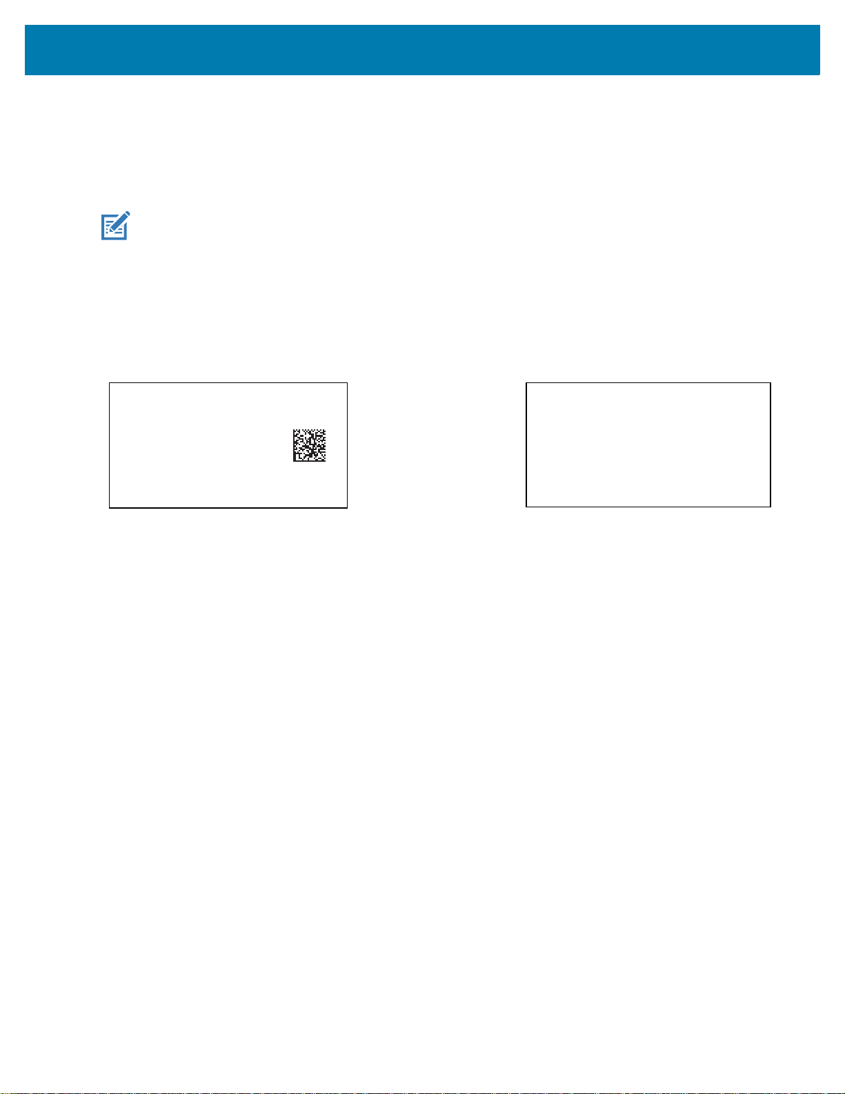
User Preferences & Miscellaneous Options
Data Carrier
FNC1
04150123456782
101A234B5
FNC1
1717231
<content dfi="GS1">
<gtin>04150123456782</gtin>
<lot>1A234B5</lot>
<exp>151231</exp>
<sn>1234567890123456</sn>
</content>
> Scanned Barcode >
securPharm Output Formatting
Parameter # 1753
SSI #
F8h 06h D9h
NOTE: securPharm output formatting is effective only when securPharm Decoding on page 96 is enabled.
securPharm Output Formatting parameter options represent bit positions. Therefore, any combination of
formatting can be used.
When you scan a securPharm Output Formatting barcode, the securPharm output is formatted in a number of
ways.
Sample GS1 Format
Product Number: GTIN Data Identifier DI Data Format Identifier: GS1
Sample GS1 Output - Feature Disabled
The output has no format:
0104150123456782101A234B517151231211234567890123456
Sample GS1 Output - No Formatting (0)
The output is a single line of characters:
<content
dfi="GS1"><gtin>04150123456782</gtin><lot>1A234B5</lot><exp>151231</exp><sn>1234567890123456</sn></content>
Sample GS1 Output - Insert Tab (1)
The output is a single line of characters with a tab inserted in the XML body:
<content
dfi="GS1">
67890123456</sn></content>
Sample GS1 Output - Insert New Line (2)
The output consists of multiple lines of characters with a new line character at the end of each line.
<content dfi="GS1">
<gtin>04150123456782</gtin>
<lot>1A234B5</lot>
<exp>151231</exp>
<sn>1234567890123456</sn>
</content>
[tab]<gtin>04150123456782</gtin>[tab]<lot>1A234B5</lot>[tab]<exp>151231</exp>[tab]<sn>12345
97
Page 98

User Preferences & Miscellaneous Options
Data Carrier
Mac06
9N11123456782
Gs
1T1A234B5
Gs
D151231
Gs
<content dfi="IFA">
<ppn>111234567842</ppn>
<lot>1A234B5</lot>
<sn>1234567890123456</sn>
</content>
> Scanned Barcode >
Sample GS1 Output - Insert Tab and New Line (3)
The output consists of multiple lines of characters with tabs and a new line character at the end of each line.
<content dfi="GS1">
[tab]<gtin>04150123456782</gtin>
[tab]<lot>1A234B5</lot>
[tab]<exp>151231</exp>
[tab]<sn>1234567890123456</sn>
</content>
Sample IFA Format
Product Number: PPNData Identifier DI Data Format Identifier: IFA
Sample GS1 Output - Feature Disabled
The output has no format:
[)>069N1112345678421T1A234B5S1234567890123456
Sample GS1 Output - No Formatting (0)
The output is a single line of characters:
<content
dfi="IFA"><ppn>111234567842</ppn><lot>1A234B5</lot><sn>1234567890123456</sn></content>
Sample GS1 Output - Insert Tab (1)
The output is a single line of characters with a tab inserted in the XML body:
<content
dfi="IFA">[tab]<ppn>111234567842</ppn>[tab]<lot>1A234B5</lot>[tab]<sn>1234567890123456</sn></content>
Sample GS1 Output - Insert New Line (2)
The output consists of multiple lines of characters with a new line character at the end of each line.
<content dfi="IFA">
<ppn>111234567842</ppn>
<lot>1A234B5</lot>
<sn>1234567890123456</sn>
</content>
98
Page 99

User Preferences & Miscellaneous Options
Sample GS1 Output - Insert Tab and New Line (3)
The output consists of multiple lines of characters with tabs and a new line character at the end of each line.
<content dfi="IFA">
[tab]<ppn>111234567842</ppn>
[tab]<lot>1A234B5</lot>
[tab]<sn>1234567890123456</sn>
</content>
securPharm Output Formatting Barcodes
Scan a barcode below to format the securPharm output.
* No Formatting
(0)
Insert New Line
(2)
Insert Tab
(1)
Insert Tab and New Line
(3)
99
Page 100

Imager Preferences
* Enable Parameter
(1)
Feature/option
* Indicates default
Option value
Introduction
You can program the imager to perform various functions, or activate different features. This chapter describes
image capture preference features and provides programming barcodes for selecting these features.
NOTE: Only the Symbol Native API (SNAPI) with Imaging interface supports image capture. See USB Device
Type on page 238 to enable this host.
The imager ships with the settings shown in Table 9 on page 101 (also see Parameter Defaults for all defaults). If
the default values suit requirements, programming is not necessary.
Setting Parameters
To set feature values, scan a single barcode or a short barcode sequence. The settings are stored in non-volatile
memory and are preserved even when the imager powers down.
To return all features to default values, scan the Set Factory Defaults on page 62. Throughout the programming
barcode menus, asterisks (
NOTE: Most computer monitors allow scanning barcodes directly on the screen. When scanning from the
screen, be sure to set the document magnification to a level where you can see the barcode clearly, and
bars and/or spaces do not merge.
*) indicate default values.
100
 Loading...