

Page 1
DS9208 Digital Scanner
Product Reference Guide
Page 2

Page 3

DS9208 Digital Scanner
Product Reference Guide
72E-139635-01
Revision A
March 2011
Page 4

ii DS9208 Product Reference Guide
© 2011 Motorola Solutions, Inc. All rights reserved.
No part of this publication may be reproduced or used in any form, or by any electrical or mechanical means,
without permission in writing from Motorola. This includes electronic or mechanical means, such as
photocopying, recording, or information storage and retrieval systems. The material in this manual is subject to
change without notice.
The software is provided strictly on an “as is” basis. All software, including firmware, furnished to the user is on
a licensed basis. Motorola grants to the user a non-transferable and non-exclusive license to use each
software or firmware program delivered hereunder (licensed program). Except as noted below, such license
may not be assigned, sublicensed, or otherwise transferred by the user without prior written consent of
Motorola. No right to copy a licensed program in whole or in part is granted, except as permitted under
copyright law. The user shall not modify, merge, or incorporate any form or portion of a licensed program with
other program material, create a derivative work from a licensed program, or use a licensed program in a
network without written permission from Motorola. The user agrees to maintain Motorola’s copyright notice on
the licensed programs delivered hereunder, and to include the same on any authorized copies it makes, in
whole or in part. The user agrees not to decompile, disassemble, decode, or reverse engineer any licensed
program delivered to the user or any portion thereof.
Motorola reserves the right to make changes to any software or product to improve reliability, function, or
design.
Motorola does not assume any product liability arising out of, or in connection with, the application or use of
any product, circuit, or application described herein.
No license is granted, either expressly or by implication, estoppel, or otherwise under any Motorola, Inc.,
intellectual property rights. An implied license only exists for equipment, circuits, and subsystems contained in
Motorola products.
MOTOROLA, MOTO, MOTOROLA SOLUTIONS and the Stylized M Logo are trademarks or registered
trademarks of Motorola Trademark Holdings, LLC and are used under license. All other trademarks are the
property of their respective owners.
Motorola Solutions, Inc.
One Motorola Plaza
Holtsville, New York 11742-1300
http://www.motorola.com
Warranty
For the complete Motorola hardware product warranty statement, go to:
http://www.motorola.com/enterprisemobility/warranty.
Page 5

Revision History
Changes to the original manual are listed below:
Change Date Description
-01 Rev A 3/2011 Initial release
iii
Page 6

iv DS9208 Product Reference Guide
Page 7

Table of Contents
About This Guide
Introduction.................................................................................................................... xv
Configurations................................................................................................................ xv
Chapter Descriptions..................................................................................................... xvi
Notational Conventions............... .. ......................................................... ........................ xvii
Related Documents ............ .......................... ... ............. .. .. ............. ... .......................... .. . xvii
Service Information........................................................................................................ xviii
Chapter 1: Getting Started
Introduction ................................................................................................................... 1-1
Interfaces ...................................................................................................................... 1-2
Unpacking ..................................................................................................................... 1-2
Setting Up the Digital Scanner .................. ..................................................... ............... 1-3
Installing the In te rface Cable ................. ... .......................... .. ............. ... .. ............. .. . 1- 3
Connecting Power (if required) ......... ...................................................................... 1-3
Configuring the Digital Scanner .............................................................................. 1-4
Mounting the Digital Scanner ........................................................................................ 1-4
Wall Mount Bracket .................................. .. ............................................................. 1-4
Locking Mount Bracket ........................................................................................... 1-5
Accessories .................................................................................................................. 1-7
Required Accessories ............................................................................................. 1-7
Optional Accessories .............................................................................................. 1-7
Electronic Article Surveill ance (EAS) (Optional) .......................................... ................. 1-7
Chapter 2: Data Capture
Introduction ................................................................................................................... 2-1
Beeper Definitions ................................ ........................................................................ 2-2
Selecting Beeper Volume using Trigger ................................................................. 2-4
LED Definitions ............................................................................................................. 2-4
Scanning .... ................... .................. .................... .................... ................. .................... . 2-5
Presentation Mode Scanning ................................................................. ................. 2-5
Momentary Trigger Mode Scanning ........................................................................ 2-6
Page 8

vi DS9208 Product Reference Guide
Decode Ranges ............................................................................................................ 2-8
Integrated Electronic Article Surveillance (EAS) ........................................................... 2-8
Deactivation Antenna for Checkpoint EAS Systems .............. ................................. 2-8
EAS Deactivation Range ....... .. ........................... .. .............................. .................... 2-8
DS9208 Host Interface Cables and EAS .................... ............................................ 2-8
Checkpoint Contact Information .............................................................................. 2-8
Chapter 3: Maintenance & Technical Specifications
Introduction ................................................................................................................... 3-1
Maintenance ................................................................................................................. 3-1
Troubleshooting ............................................................................................................ 3-2
Report Software Version Bar Code .................... ................................. .................... 3-4
Technical Specifications ............................................................................................... 3-5
Digital Scanner Signal Descriptions .............................................................................. 3-7
Chapter 4: User Preferences & Miscellaneous Digital Scanner Options
Introduction ................................................................................................................... 4-1
Scanning Sequence Examples ..................................................................................... 4-2
Errors While Scanning .................................................................................................. 4-2
User Preferences/Miscellaneous Options Parameter Defaults ............................... .. .... 4-2
User Preferences .......................................................................................................... 4-4
Set Default Parameter ............................................................................................ 4-4
Parameter B a r Co de S c a nn ing ................. ............. .. ............. .. ... ............. .. ............. . 4- 5
Beep After Good Decode .................................................................. .. .................... 4-5
Beeper Tone .................................................... .. ............................. ........................ 4-6
Beeper Volume ................... ............................................. ....................................... 4-7
Volume Adjustment Trigger Timeout ............................ ......................... ................. 4-8
Beeper Duration ........................... ......................... .......................... ........................ 4-9
Suppress Power-up Beeps ............................................................. ........................ 4-9
Low Power Mode ............................................................... .. ................................. .. 4-10
Time Delay to Low Power Mode ............................................................................. 4-11
Trigger Mode ...................................................................... ........................... .......... 4-13
Trigger Aiming Pattern ............................................................................................ 4-14
Presentation Aiming Pattern ................................................................................... 4-15
Momentary Trigger Mode Timeout .......................................................................... 4-16
Motion Detect Range ................... ......................................................................... .. 4-17
Post Decode Illumination ........... ......................... .......................... .......................... 4-18
Presentation Mode Field of View ........................................................ .................... 4-18
Picklist Mode ................................................................. .......................................... 4-19
Continuous Bar Code Read ...................................... .............................................. 4-20
Unique Bar Code Reporting .................................. .. ............................. .. ................. 4-20
Decode Session Timeout ........................................................................................ 4-21
Timeout Between Decodes, Same Symbol ............................................................ 4-21
Timeout Between Decodes, Different Symbols ...................................................... 4-22
Fuzzy 1D Processing .............................................................................................. 4-22
Decode Mirror Images (Data Matrix Only) .............................................................. 4-23
Mobile Phone/Display Mode ................................................................................... 4-24
PDF Prioritization .................................................................................................... 4-25
Page 9

PDF Prioritization Timeout ...................... ..................................................... ........... 4-25
Decoding Illumination (Hand-Held Mode Only) ............................. .......................... 4-26
Multicode Mode .......................................... ............................................................. 4-27
Multicode Expression .................................................... ......................... ................. 4-28
Multicode Mode Concatenation .......... ................................... .. ............................... 4-33
Multicode Concatenation Symbology ...................................................................... 4-34
Multicode Troubleshooting ............................. ............................... .. ........................ 4-35
Miscellaneous Scanner Parameters ................................... ............................... ........... 4-37
Transmit Code ID Character ................................................................................... 4-37
Prefix/Suffix V a lu e s . ... .......................... .. .............. .. .. ............. .. ........................... .. ... 4-38
Scan Data Tran s m is s io n Fo r m a t .. ... ............. .. ........................... .. ............. .. ... ......... 4-39
FN1 Substitution Values ......................................................................................... 4-41
Transmit “No Read” Message ....................................................... .......................... 4-42
Chapter 5: Imaging Preferences
Introduction ................................................................................................................... 5-1
Scanning Sequence Examples ..................................................................................... 5-2
Errors While Scanning .................................................................................................. 5-2
Imaging Pref e re n c e s Pa ra meter Defaults ............... ... .......................... .. ....................... 5-2
Imaging Pref e re n c e s ........ ............. .. .. .............. .. ............. .. .. .............. .. .......................... . 5- 4
Operational Modes ................. ............................... ............................... .. ................. 5-4
Image Capture Illumination ..................................................................................... 5-5
Snapshot Mode Timeout ..................................... .. ................................. ................. 5-6
Snapshot Aiming Pattern ............... ........................... .............................................. 5-6
Image Cropping ...................................................................................................... 5-7
Crop to Pixel Addresses ......................................................................................... 5-8
Image Size (Number of Pixels) ............................................................................... 5-9
Image Brightness (Target White) ............................................................................ 5-10
JPEG Image Options ..................... ................................................. ........................ 5-10
JPEG Target File Size ............................................................................................ 5-11
JPEG Quality and Size Value ................................................................................. 5-11
Image Enhancement ............................................................................................... 5-12
Image File Format Selector ..................................................................................... 5-13
Image Rotation ........................................................................................................ 5-14
Bits Per Pixel ........................... .. ............. ... .. ............. .. ........................... .. ................ 5-15
Signature Capture ............................. ...................................................................... 5-16
Signature Capture File Format Selector ................................................................. 5-17
Signature Capture Bits Per Pixel ...................................................... ...................... 5-18
Signature Capture Width ......................................................................................... 5-19
Signature Capture Height .................................. ............................. ........................ 5-19
Signature Capture JPEG Quality ........................................................ .................... 5-19
Table of Contents vii
Chapter 6: USB Interface
Introduction ................................................................................................................... 6-1
Connecting a USB Interface .......................................................... ............................... 6-2
USB Parameter Defaults ........................................................... ........................ ........... 6-3
USB Host Parameters ................... ............................. .................................................. 6-4
USB Device Type ......................... ........................................................................... 6-4
Page 10

viii DS9208 Product Reference Guide
Symbol Native API (SNAPI) Status Handshaking .............. ............................... .. .... 6-5
USB Country Keyboard Types - Country Codes .................. .. ............................... .. 6-6
USB Keystroke Delay ....................................................................... ...................... 6-8
Simulated Caps Lock .............................................................................................. 6-9
USB CAPS Lock Override ................ ...................................................................... 6-9
USB Ignore Unknown Characters ....................................................................... .. .. 6-10
USB Convert Unknown to Code 39 ......................................... ........................... .. .. 6-10
USB Ignore Beep Directive ..................................... .. .. ............................................ 6-11
USB Ignore Type Directive ..................................................................................... 6-11
Emulate Keypad ..................... .................................................................. .. ............. 6-12
Emulate Keypad with Leading Zero .............................. .......................................... 6-12
USB Keyboard FN 1 Substitution ............... .. ............................. .............................. 6-13
Function Key Mapping ............................................................................................ 6-13
Convert Cas e ........ .. ........................... .. ........................... .. ............. .. .. .............. .. ..... 6-14
USB Static CDC ............................. .................................... .. ................................... 6-14
USB Polling Interval ................................. .. .. ................................. .. ........................ 6-15
Quick Keypad Emulation ..................... .. .. ................................................................ 6-17
ASCII Character Set for USB ........................................................................................ 6-18
Chapter 7: RS-232 Interface
Introduction ................................................................................................................... 7-1
Connecting an RS-232 Interface .............. ............................. .. ..................................... 7-2
RS-232 Parameter Defaults ................. ......................................................................... 7-3
RS-232 Host Parameters ..................... ....................... .................................................. 7-4
RS-232 Host Types ................................................................................................. 7-6
Baud Rate ......................................... .. .. ................................... ............................... 7-8
Parity ...... ............. ........... ............. .............. ........... ............. ............. ........... ............. . 7-9
Stop Bits .............. .. ........................... .. ............. .. ... ............. .. ........................... .. ....... 7-10
Data Bits ......... ............. .. .. ............. ... .......................... .. .............. .. .. ............. ... ......... 7-10
Check Recei ve E rrors ............... ............. ... .......................... .. ............. ... .. ............. .. . 7- 1 1
Hardware Handshaking ............................................................................... ........... 7-11
Software Ha nd s h a k in g ............ .. ............. ... .. ............. .. ............. ... ............. .. .. ............ 7-13
Host Serial Re s p o nse T i me -out ................ .......................... .. ............. ... .. ............. .. . 7- 1 5
RTS Line Stat e .. ............. .. ............. ... .. ............. .. .............. .. .......................... ... ......... 7-16
Beep on <BEL> ................... ......................................................................... ........... 7-16
Intercharacter Delay ................................................................................................ 7-17
Nixdorf Beep/LED Options ................................. ..................................................... 7-18
Ignore Unknown Characters ................................................................................... 7-18
ASCII Character Set for RS-232 ................................................................................... 7-19
Chapter 8: IBM 468X / 469X Interface
Introduction ................................................................................................................... 8-1
Connecting to an IBM 468X/469X Host ................................................................ ........ 8-2
IBM Parameter Defaults ............................................................................................... 8-3
IBM 468X/469X Host Parameters .............................................................. ................... 8-4
Port Address ........................................................................................................... 8-4
Convert Unk now n to C o d e 39 . .. ............. ... .. ............. .. ........................... .. ................ 8-5
Ignore Beep Directive ......................................................................... .................... 8-5
Page 11

Ignore Configuration Directive ................................................................................ 8-6
Chapter 9: Keyboard Wedge Interface
Introduction ................................................................................................................... 9-1
Connecting a Keyboard Wedge Interface ................. .. .................................................. 9-2
Keyboard Wedge Parameter Defaults ................................ ........................... .. ............. 9-3
Keyboard Wedge Host Parameters ............ .................................................................. 9-4
Keyboard Wedge Host Types .......................... ....................................................... 9-4
Keyboard Wedge Country Types - Country Codes ........................................... ...... 9-5
Ignore Unknown Characters ................................................................................... 9-7
Keystroke Delay ...................................................................................................... 9-7
Intra-Keystroke Delay ............................................................................................. 9-8
Alternate Nu m e ri c K e y p ad E m u la tion ............... .............. .. .......................... ... ......... 9-8
Simulated Caps Lock .............................................................................................. 9-9
Caps Lock Ove rride ..... ............. .. .. .............. .. .......................... ... ............. .. .. ............ 9- 9
Convert Wedge Data ........................................................... ................................... 9-10
Function Key Mapping ............................................................................................ 9-10
FN1 Substitution ..................................................................................................... 9-11
Send Make and Break .................................................................. .......................... 9-11
Keyboard Maps ....................................................................................................... 9-12
ASCII Character Set for Keyboard Wedge ................................................................... 9-13
Table of Contents ix
Chapter 10: Symbologies
Introduction ................................................................................................................... 10-1
Scanning Sequence Examples ..................................................................................... 10-1
Errors While Scanning .................................................................................................. 10-2
Symbology Parameter Defaults .................................................................................... 10-2
Disable All Co d e Ty p es ........... ........................... .. ........................... .. ............. .. ... ......... 10-7
UPC/EAN ...................................................................................................................... 10-8
Enable/Disable UPC-A ............................................................................................ 10-8
Enable/Disable UPC-E ............................................................................................ 10-8
Enable/Disable UPC-E1 .......................................................................................... 10-9
Enable/Disable EAN-8/JAN-8 ................................................................................. 10-9
Enable/Disable EAN-13/JAN-13 ............................................................................. 10-10
Enable/Disable Bookland EAN ................................. ............................. .. ............... 10-10
Bookland ISBN Format ........................................................................................... 10-11
Decode UPC/EAN/JAN Supplementals .................................................................. 10-12
User-Programmable Supplementals .................................. ................................. .. .. 10-15
UPC/EAN/JAN Supplemental Redundancy ............................................................ 10-15
UPC/EAN/JAN Supplemental AIM ID Format .................. .. ................................. .. .. 10-16
Transmit UPC-A Check Digit .................................................................................. 10-17
Transmit UPC-E Check Digit .................................................................................. 10-17
Transmit UPC-E1 Check Digit ................................................................................ 10-18
UPC-A Preamble ................ .................................................................................... 10-18
UPC-E Preamble ................ .................................................................................... 10-19
UPC-E1 Preamble .............. ................................................................ .................... 10-20
Convert UPC-E to UPC-A ....................................................................................... 10-21
Convert UPC-E1 to UPC-A ..................................................................................... 10-21
Page 12

x DS9208 Product Reference Guide
EAN-8/JAN-8 Extend .............................................................................................. 10-22
UCC Coupon Extended Code ................................................................................. 10-22
Coupon Report ........................................................................................................ 10-23
ISSN EAN ............................................................................................................... 10-24
Code 128 ........................................... .. .................................... .. ................................... 10-25
Enable/Disable Code 128 ....................................................................................... 10-25
Set Lengths for Code 128 ............................................................. .......................... 10-25
Enable/Disable GS1-128 (formerly UCC/EAN-128) ................................................ 10-26
Enable/Disable ISBT 128 ........................................................................................ 10-27
ISBT Concatenation ................................................................................................ 10-28
Check ISBT Ta bl e .............. ... ............. .. .. .............. .. .......................... .. ..................... 10-29
ISBT Concatenation Redundancy ........................................................................... 10-29
Code 39 ........................................... .. .. .................................... ..................................... 10-30
Enable/Disable Code 39 ..................... ............................... ............................... .. .... 10-30
Enable/Disable Trioptic Code 39 ............................................................................ 10-30
Convert Code 39 to Code 32 .................................................................................. 10-31
Code 32 Prefix ..................... .............................. ..................................................... 10-31
Set Lengths for Code 39 ............................................................. ............................ 10-32
Code 39 Check Digit Verification ................... ............................... .. ........................ 10-33
Transmit Code 39 Check Digit ................................................................................ 10-33
Code 39 Full ASCII Conversion .................................... .......................................... 10-34
Code 39 Buffering - Scan & Store .................. ......................................................... 10-35
Code 93 ........................................... .. .. .................................... ..................................... 10-37
Enable/Disable Code 93 ..................... ............................... ............................... .. .... 10-37
Set Lengths for Code 93 ............................................................. ............................ 10-37
Code 11 ........................................... .. .. .................................... ..................................... 10-39
Code 11 ........................................................... ........................ ....................... ........ 10-39
Set Lengths for Code 11 ............................................................. ............................ 10-39
Code 11 Check Digit Verification ................... ............................... .. ........................ 10-41
Transmit Code 11 Check Digits .............................................................................. 10-42
Interleaved 2 of 5 (ITF) ................................................................................................. 10-42
Enable/Disable Interleaved 2 of 5 ....................... .................................................... 10-42
Set Lengths for Interleaved 2 o f 5 ............... .. .......................... ... ............. .. .............. 10-43
I 2 of 5 Check Digit Verification ............................................................................... 10-45
Transmit I 2 of 5 Check Digit ................................................................................... 10-45
Convert I 2 of 5 to EAN-13 .................. ............................. ............................. .......... 10-46
Discrete 2 of 5 (DTF) .................................................................................................... 10-46
Enable/Disable Discrete 2 of 5 ....................................... ......................................... 10-46
Set Lengths for Discrete 2 of 5 ... .. ... ............. .. ............. ... ............. .. .. .............. .. ....... 10-47
Codabar (NW - 7) ......................................................................................................... 10-49
Enable/Disable Codabar ......................................................................................... 10-49
Set Lengths for Codabar ......................................................................................... 10-49
CLSI Editing .......... ........................... .. .......................... ... ............. .. .. .............. .. ....... 10-51
NOTIS Editing ......................................................................................................... 10-51
MSI ............................................................................................................................... 10-52
Enable/Disable MSI ................................................................................................ 10-52
Set Lengths for MSI ..... .. ........................... .. .......................... .. .............. .. .. ............. . 10 - 5 2
MSI Check Digits .................................................................................................... 10-54
Transmit MSI Check Digit(s) ................................................................................... 10-54
MSI Check Digit Algorithm ................... .. ... ............. .. ............. .. ........................... .. ... 10-55
Page 13

Table of Contents xi
Chinese 2 of 5 ............................................................................................................... 10-55
Enable/Disable Chinese 2 of 5 ............................................... ............................... .. 10-55
Matrix 2 of 5 ..... ............. ... .......................... .. ........................... .. ............. .. ... ............. .. ... 10-56
Enable/Disable Matrix 2 of 5 ................................................................................... 10-56
Set Lengths for Matrix 2 of 5 ................................................................................... 10-57
Matrix 2 of 5 Chec k D ig it ........... .. ........................... .. ............. .. ... ............. .. .............. 10-58
Transmit Matrix 2 of 5 Check Digit .......................................................................... 10-58
Korean 3 of 5 ................................................................................................................ 10-59
Enable/Disable Korean 3 of 5 ................................................................................. 10-59
Inverse 1D .................................................................................................................... 10-60
Postal Codes ............ ............. .. ........................... .. ............. ... .. ............. .. ....................... 10-61
US Postnet .............................................................................................................. 10-61
US Planet ............................. .................................................. ................................. 10-61
Transmit US Po s ta l C h e ck D ig it ......... .. .. .............. .. ............. .. .. .............. .. ................ 10-62
UK Postal ................................................................................................................ 10-62
Transmit UK Po s ta l C h e ck D ig it ......... .. .. .............. .. ............. .. .. .............. .. ................ 10-63
Japan Postal ........................................................................................................... 10-63
Australia Post .......................................................................................................... 10-64
Australia Post Format ............................................................................................. 10-65
Netherlands KIX Code ........................................................................................... 10-66
USPS 4CB/One Code/Intelligent Mail ..................................................................... 10-66
UPU FICS Postal .................................................................................................... 10-67
GS1 DataBar ................................................................................................................ 10-68
GS1 DataBar ........................................................................................................... 10-68
GS1 DataBar Limited .............................................................................................. 10-69
GS1 DataBar Limited Security Level ...................................................................... 10-70
GS1 DataBar Expanded ................ .................................. ................................... .... 10-71
Convert GS1 DataBar to UPC/EAN ........................................................................ 10-71
Composite .. ........ ......... ....... ......... ........ ......... ....... ......... ......... ...... ......... ......... ....... ........ . 10-72
Composite CC -C ......................... .. .............. .. .. ............. ... .......................... .. ............ 10- 7 2
Composite CC -A/B ....... .. .. ............. ... ............. .. .. .............. .. .......................... ... ......... 10-7 2
Composite TL C -3 9 ............. ... .......................... .. .............. .. .. ............. .. ..................... 10-73
UPC Composite Mode ............................................................................................ 10-73
Composite Beep Mode ................... ........................................................................ 10-74
GS1-128 Emulation Mode for UCC/EAN Composite Codes ...................... .. ........... 10-74
2D Symbologies ............................................................................................................ 10-75
Enable/Disable PDF417 .......................................................................................... 10-75
Enable/Disable MicroPDF417 ................................................................................. 10-75
Code 128 Emulation ................ .. ..................................................................... .. .. .... 10-76
Data Matrix . ........................... .. ............. .. ... ............. .. .......................... ... .................. 10-77
Data Matrix Inverse ................................................................................................. 10-77
Maxicode ................................................................................................................. 10-78
QR Code ..................................... .. .............. .. ............. .. ... ............. .. ............. ... .. ....... 10-78
QR Inverse ... ........................... .. ........................... .. ............. .. .. .............. .. .. ............. . 10 - 7 9
MicroQR ... ............... .............. ............... ................ ............. ............... ................ ....... 10-7 9
Aztec ...... ........................ ........................ ...................... ......................... .................. 10-80
Aztec Inverse .......................................................................................................... 10-80
Redundancy Level .............. ................................................................ .......................... 10-81
Redundancy Level 1 ......................... ................................................................ ...... 10-81
Redundancy Level 2 ......................... ................................................................ ...... 10-81
Page 14

xii DS9208 Product Reference Guide
Redundancy Level 3 ......................... ................................................................ ...... 10-81
Redundancy Level 4 ......................... ................................................................ ...... 10-82
Security Lev el .. .. .............. .. .. ............. .. .............. .. .......................... ... ............. .. ............. . 10-83
Intercharacter Gap Size .......................................................................................... 10-84
Macro PDF Features ......................... ................................. ................................ .. ........ 10-85
Flush Macro Buffer .................................................................................................. 10-85
Abort Macro PDF Entry ........................................................................................... 10-85
Chapter 11: 123Scan2
Introduction ................................................................................................................... 11-1
Communication with 123Scan2 .................................................................................... 11-1
123Scan2 Requirements ............................................................. ...................... ........... 11-1
Chapter 12: Advanced Data Formatting
Introduction ................................................................................................................... 12-1
Chapter 13: Driver’s License Set Up (DS9208-DL)
Introduction ................................................................................................................... 13-1
Driver’s License Parsing ............................................................................................... 13-2
Parsing Driver’s License Data Fields (Embedded Dri ver's License Parsing) ............... 13-3
Embedded Driver's License Parsing Criteria - Code Type ......... ............................ 13-3
Driver’s License Parse Field Bar Codes ............... .. ............................. ................... 13-4
AAMVA Parse Field Bar Codes .............................. ................................. .. .. ........... 13-7
Parsing Rule Example .................................................................................................. 13-17
Embedded Driver's License Parsing ADF Example ................................................ 13-21
Field Update Procedure .................................................... ............................... .. ........... 13-23
User Preferences .......................................................................................................... 13-24
Set Default Parameter ............................................................................................ 13-24
Send Keystroke (Control Characters and Keyboard Characters) ........................... 13-24
Appendix A: Standard Default Parameters
Appendix B: Programming Reference
Symbol Code Identifiers ............................................................................ .................... B-1
AIM Code Identifiers .................. ........................................................................ ........... B-3
Appendix C: Sample Bar Codes
Code 39 ........................................... .. .. .................................... ..................................... C-1
UPC/EAN ...................................................................................................................... C-1
UPC-A, 100% .......................................................................................................... C-1
EAN-13, 100% ......................... ............................................................................... C-2
Code 128 ........................................... .. .................................... .. ................................... C-2
Interleaved 2 of 5 .......................................................................................................... C-2
GS1 DataBar-14 ........................................................................................................... C-3
Page 15

PDF417 ......................................................................................................................... C- 3
Data Matrix ............. .. ............. .. ... ............. .. ........................... .. ............. .. .. .............. .. ..... C-3
Maxicode ...................................................................................................................... C-4
QR Code ............ ... .. ............. .. ............. ... ............. .. .. .............. .. ............. .. ....................... C-4
US Postnet .................................................................................................................... C-4
UK Postal ...................................................................................................................... C-4
Appendix D: Numeric Bar Codes
Numeric Bar Codes ............................. .................................. .. .. ................................... D-1
Cancel ... ....... ...... ....... .... ....... ....... .... ....... ...... ..... ...... ....... ....... .... ....... ...... ..... ...... ....... ..... D-2
Appendix E: ASCII Character Sets
Appendix F: Signature Capture Code
Introduction ................................................................................................................... F-1
Code Structure .................. .................................................. .......................................... F-1
Signature Capture Area .......................................... ................................................ F-1
CapCode Pattern Structure ..................... .................................. .. ............................ F-2
Start / Stop Patterns ..................................................................................................... F-2
Dimensions ................................................................................................................... F-3
Data Format .............. .......................... ... .......................... .. .............. .. .. ............. ... ......... F-3
Additional Capabilities ........ ..................................................... ..................................... F-4
Signature Boxes ................... ............................... ............................... .. ........................ F-4
Table of Contents xiii
Index
Page 16

xiv DS9208 Product Reference Guide
Page 17

About This Guide
Introduction
The DS9208 Product Reference Guide provides general instructions for setting up, operating, maintaining, and
troubleshooting the DS9208 digital scanner.
Configurations
This guide includes the following DS9208 digital scanner configurations:
•
DS9208-SR00004NNWW - DS9208 Digital Scanner, Standard Range, Black
•
DS9208-SR00004CNWW - DS9208 Digital Scanner, Standard Range, Black, Checkpoint EAS
•
DS9208-DL00004NNWW - DS9208 Digital Scanner, DL parsing, Standard Range, Black
•
DS9208-DL00004CNWW - DS9208 Digital Scanner, DL parsing, Standard Range, Black, Checkpoint EAS
Page 18

xvi DS9208 Product Reference Guide
Chapter Descriptions
Topics covered in this guide are as follows:
•
Chapter 1, Getting Started provides a product overview, unpacking instructions, and cable connection
information.
•
Chapter 2, Data Capture describes parts of the digital scanner, beeper and LED definitions, and how to use
the scanner in hand-held and hands-free (presentation) modes.
•
Chapter 3, Maintenance & Technical Specifications provides information on how to care for the digital
scanner, troubleshooting, and technical speci fic at ion s.
•
Chapter 4, User Preferences & Miscellaneous Digital Scanner Options describes features frequently used to
customize how data transmits to the host device and programming bar codes for selecting user preference
features for the digital scanner.
•
Chapter 5, Imaging Preferences provides imaging preference features and programming bar codes for
selecting these feature s.
•
Chapter 6, USB Interface describes how to set up the digital scanner with a USB host.
•
Chapter 7, RS-232 Interface describes how to set up the digital scanner with an RS-232 host, such as
point-of-sale devices, host computers, or other devices with an available RS-232 port.
•
Chapter 8, IBM 468X / 469X Interface describes how to set up the digital scanner with IBM 468X/469X POS
systems.
•
Chapter 9, Keyboard Wedge Interface describes how to set up a Keyboard Wedge interface with the digital
scanner.
•
Chapter 10, Symbologies describes all symbology features and provides programming bar codes for
selecting these features for the digital scanner.
•
Chapter 11, 123Scan2 describeds this PC-based scanner configuration tool which enables rapid and easy
customized setup of Symbol scanners.
•
Chapter 12, Advanced Data Formatting briefly describes ADF, a means of customizing data before
transmission to the host device, and includes a reference to the ADF Programmer Guide.
•
Chapter 13, Driver’s License Set Up (DS9208-DL) describes how the DS9208-DL digital scanner can parse
out information from standard US driver's licenses and certain other American Association of Motor Vehicle
Administrators (AAMVA) compliant ID cards.
•
Appendix A, Standard Default Parameters provides a table of all host devices and miscellaneous scanner
defaults.
•
Appendix B, Programming Reference provides a table of AIM code identifiers, ASCII character conversions,
and keyboard maps.
•
Appendix C, Sample Bar Codes includes sample bar codes of various code types.
•
Appendix D, Numeric Bar Codes includes the numeric bar codes to scan for parameters requiring specific
numeric values.
•
Appendix E, ASCII Character Sets provides ASCII character value tables.
•
Appendix F, Signature Capture Code provides information on CapCode, a signature capture code that
encloses a signature area on a document and allows a scanner to capture a signature.
Page 19

Notational Conventions
*Baud Rate 9600
Feature/Option
* Indicates Default
The following conventions are used in this document:
•
Italics are used to highlight the following:
• Chapters and sections in this and related documents
• Dialog box, window and screen names
• Drop-down list and list box names
• Check box and radio button names
•
Bold text is used to highlight the following:
• Key names on a keypad
• Button names on a screen.
•
bullets (•) indicate:
• Action items
• Lists of alternatives
• Lists of required steps that are not necessarily sequential
About This Guide xvii
•
Sequential lists (e.g., those that describe step-by-step procedures) appear as numbered lists.
•
Throughout the programming bar code menus, asterisks (*) are used to denote default parameter settings.
Related Documents
•
DS9208 Quick Start Guide, p/n 72-140088-xx - provides general information for getting started with the
DS9208 digital scanner, and includes basic set up and operation instructions.
•
Advanced Data Formatting Programmer Guide, p/n 72E-69680-xx - provides information on ADF , a means of
customizing data before transmission to a host.
For the latest version of this guide and all Motorola guides, go to: http://supportcentral.motorola.com.
Page 20

xviii DS9208 Product Reference Guide
Service Information
If you have a problem with your equipment, contact Motorola Solutions support for your region. Contact information
is available at: http://supportcentral.motorola.com.
When contacting Motorola Solutions support, please have the following information available:
•
Serial number of the unit
•
Model number or product name
•
Software type and version number
Motorola responds to calls by e-mail, telephone or fax within the time limits set forth in service agreements.
If your problem cannot be solved by Motorola Solutions support, you may need to return your equipment for
servicing and will be given specific directions. Motorola is not responsible for any damages incurred during
shipment if the approved shipping container is not used. Shipping the units improperly can possibly void the
warranty.
If you purchased your business product from a Motorola business partner, please contact that business partner for
support.
Page 21
Chapter 1 Getting Started
Introduction
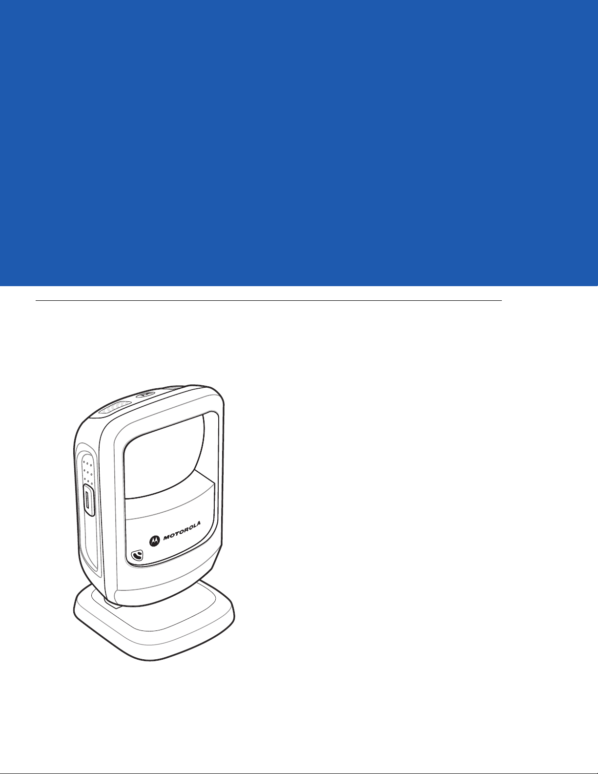
The DS9208 combines superior 1D and 2D omnidirectional bar code scanning and advanced feature set in a
compact design. The digital scanner’s built-in stand seamlessly accommodates both counter-top and hand-held
use. Whether in presentation or trigger mode, the digital scanner ensures comfort and ease of use for extended
periods of time.
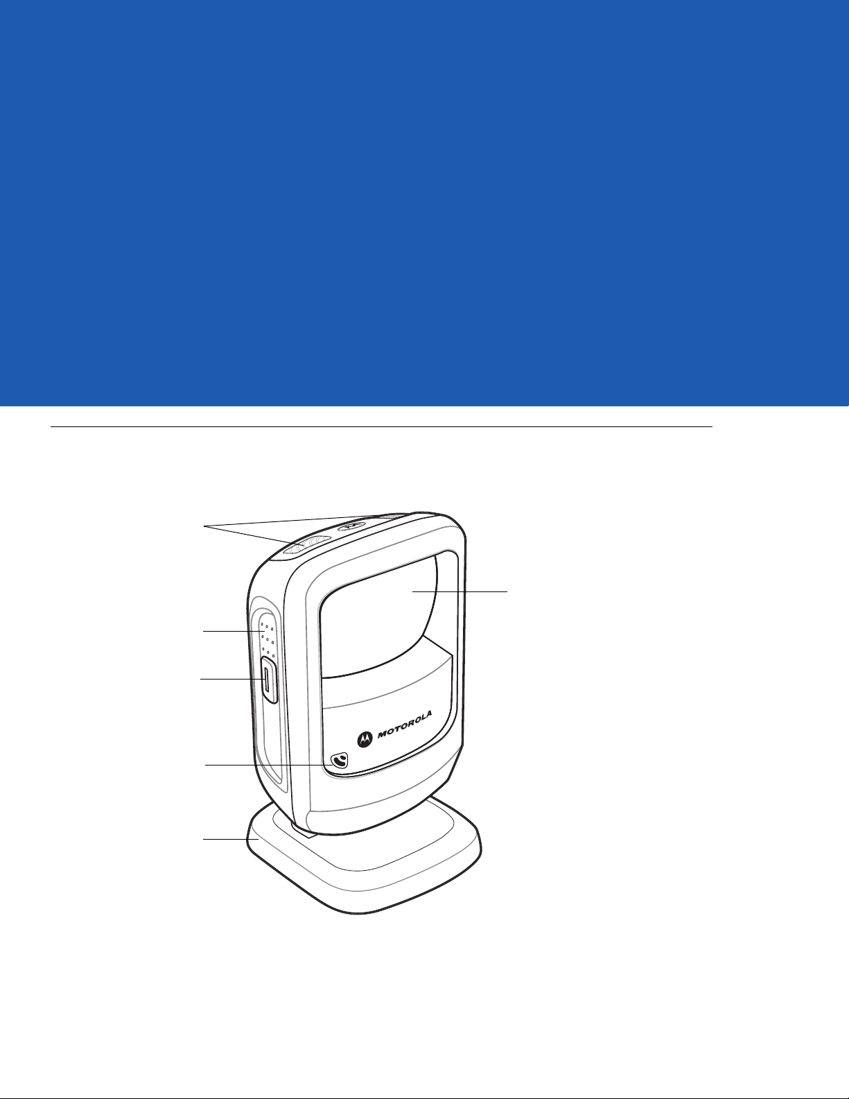
Figure 1-1
DS9208 Digital Scanner
Page 22

1 - 2 DS9208 Product Reference Guide
Interfaces
The DS9208 digital scanner supports:
•
USB connection to a host. The digital scanner autodetects a USB host and defaults to the HID keyboard
interface type. Select other USB interface types by scanning programming bar code menus.This interface
supports the following international keyboards (for Windows® environment): North America, German,
French, French Canadian, Spanish, Italian, Swedish, UK English, Portuguese-Brazilian, and Japanese.
•
Standard RS-232 connection to a host. Scan bar code menus to set up communication of the digital scanner
with the host.
•
RS-485 connection to IBM 468X/469X hosts. Scan bar code menus to set up communication of the digital
scanner with the IBM terminal.
•
Keyboard Wedge connection to a host. The host interprets scanned data as keystrokes. Scan bar code
menus to set up communication of the digital scanner with the host. This interface supports the following
international keyboards (for Windows® environment): North America, German, French, French Canadian,
French Belgian, Spanish, Italian, Swedish, UK English, Portuguese-Brazilian, and Japanese.
NOTE Only the Symbol Native API (SNAPI) with Imaging interface supports image capture. See USB Device
Type on page 6-4 to enable this host.
Unpacking
Remove the digital scanner from its packing and inspect it for damage. If the scanner was damaged in transit,
contact Motorola Enterprise Mobility Support. See page xviii for contact informa tion. KEEP THE PACKING. It is the
approved shipping container; use this to return the equipment for servicing.
Page 23
Setting Up the Digital Scanner
Interface cable
modular connector
To host
Cable interface port
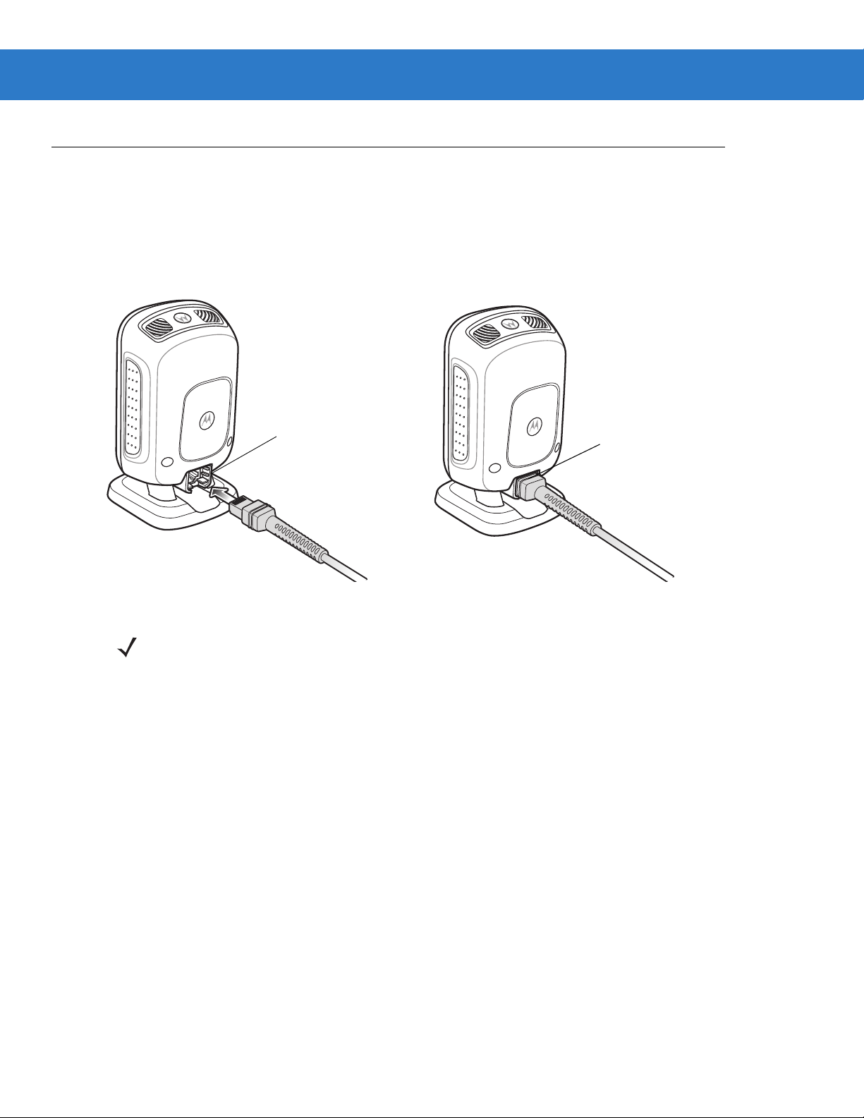
Installing the Interface Cable
1. Insert the interface cable modular connector into the interface cable port on the rear of the digital scanner until
you hear a click. The green LED lights and low/medium/high beeps sound, indicating that the scanner is
operational.
Getting Started 1 - 3
Figure 1-2
2. Gently tug the cable to ensure the connector is secure.
3. Connect the other end of the interface cable to the host (see the specific host chapter for information on host
connections).
Installing the Cable
NOTE Different host s require dif fere nt cable s. The c onnec tors illust rate d in each host cha pter are ex amples only.
Connectors vary from those illustrated, but the steps to connect the digital scanner are the same.
Removing the Interface Cable
1. Tilt the scanner fully forward.
2. Using the tip of a small screwdriver, depress the cable’s modular connector clip and carefully slide out the
cable.
Connecting Power (if required)
If the host does not provide power to the digital scanner, connect an external power supply.
1. Plug the power supply into the power jack on the interface cable.
2. Plug the other end of the power supply into an AC outlet.
Page 24
1 - 4 DS9208 Product Reference Guide
Configuring the Digital Scanner
To configure the digital scanner use the bar codes included in this manual, or use the 123Scan2 configuration
program. See Chapter 4, User Preferences & Miscellaneous Digital Scanner Options, Chapter 5, Imaging
Preferences, and Ch apte r 10, Symbo lo gie s for information about programming the digital scanner using bar code
menus. See Chapter 11, 123Scan2 for information on using this configuration program. Also see each host-specific
chapter to set up connection to a specific host type.
Mounting the Digital Scanner
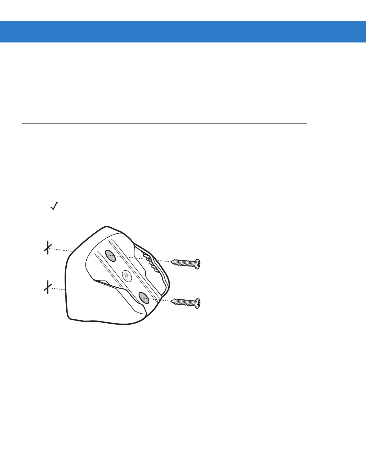
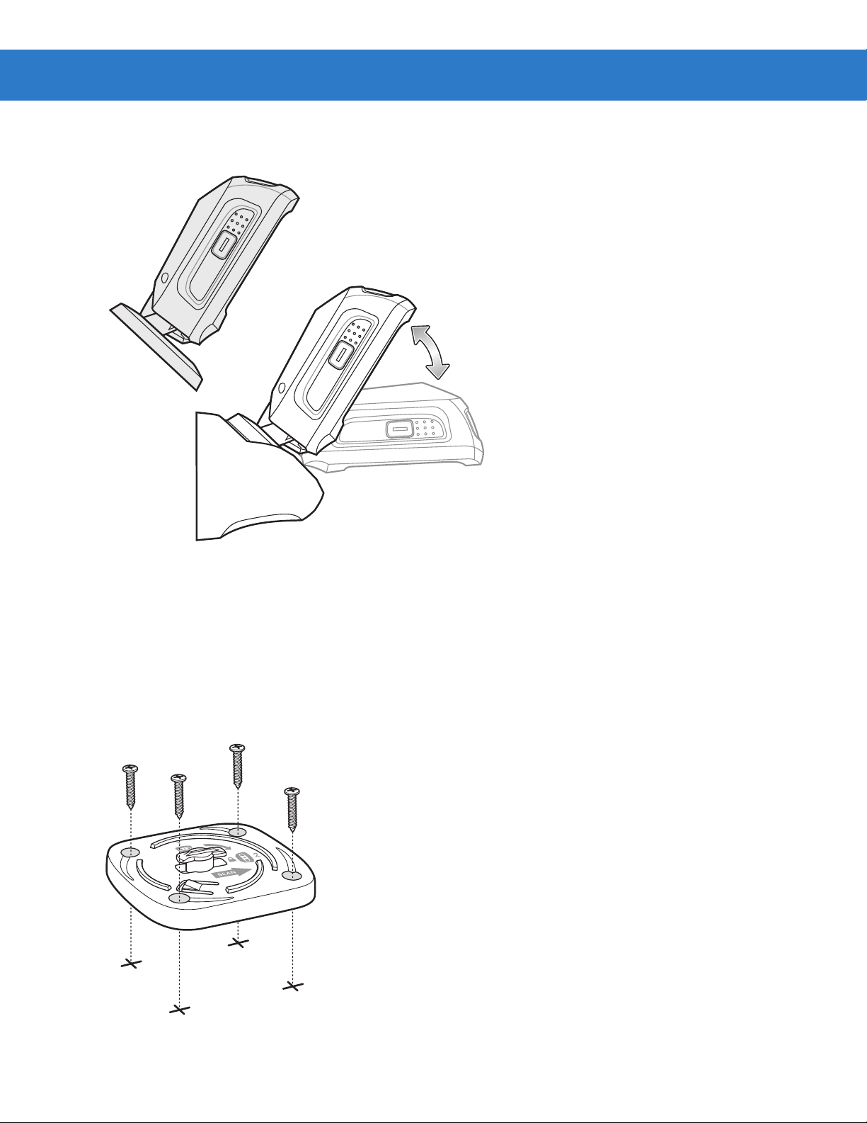
Wall Mount Bracket
An optional wall mount bracket is available for mounting the scanner to a wall or other vertical surface. To mount
the DS9208:
1. Place the bracket in its desired location on the wall, and insert two #8 screws through each screw hole in the
bracket.
NOTE Select a screw type and length appropriate for the wall material.
Figure 1-3
2. Tighten the screws to secure the bracket to the wall.
Installing the Wall Mount Bracket
Page 25
Getting Started 1 - 5
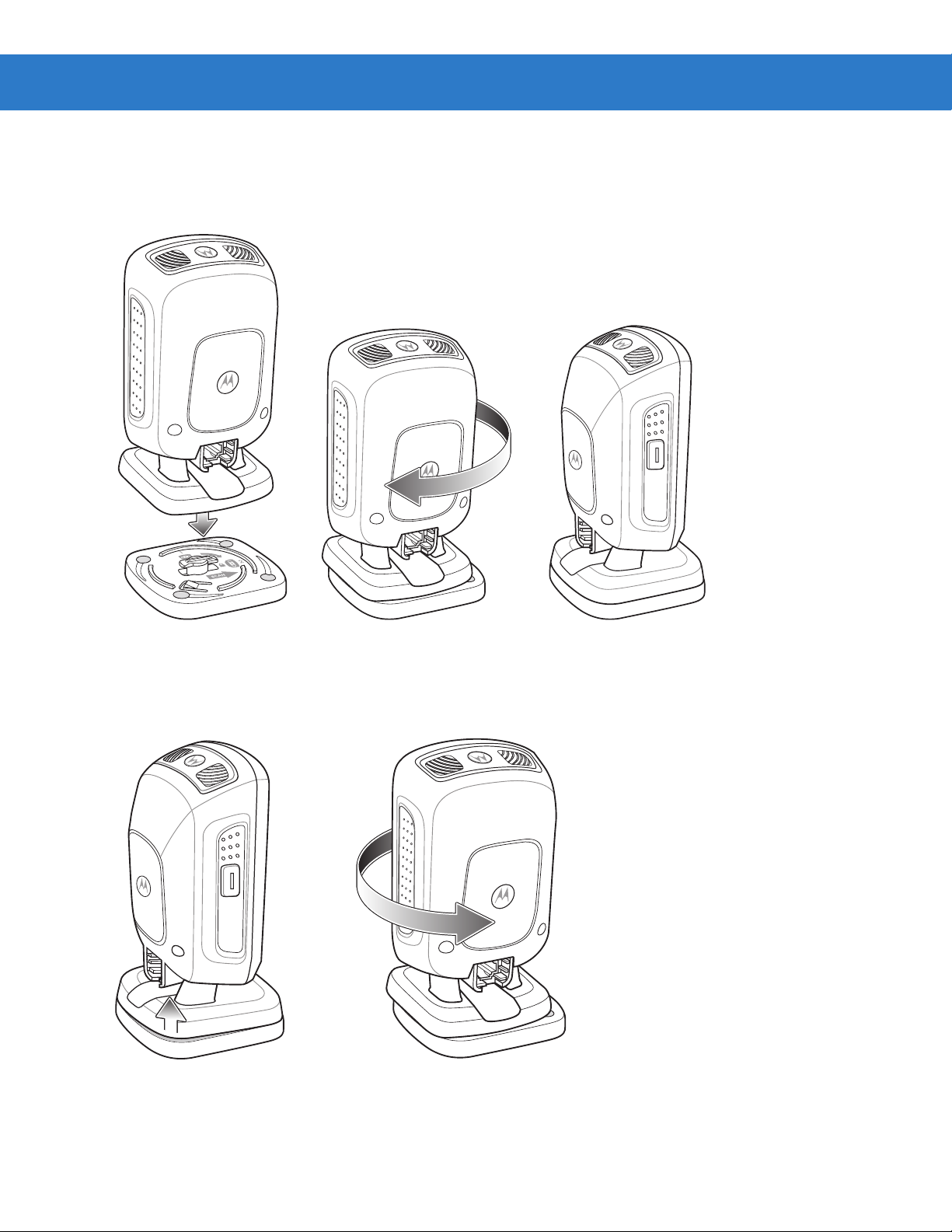
3. Slide the base of the digital scanner into the bracket, oriented so the scan window faces down.
Figure 1-4
Inserting the DS9208 into the Wall Mount Bracket
Locking Mount Bracket
An optional locking mount bracket is available for "locking" the scanner into position on a horizontal (or vertical)
surface. This option is recommended for applications where it is desirable to affix the scanner to a counter or
desktop. To mount the DS9208:
1. Place the bracket in its desired location on the counter or desktop. Make sure that the indicator on the bracket
is consistent with the direction that the scanner will face. Insert four #8 screws through each screw hole in the
bracket.
Figure 1-5
Figure 1-4 Installing the Locking Mount Bracket
Page 26
1 - 6 DS9208 Product Reference Guide
2. Tighten the screws to secure the bracket to the counter or desktop.
3. To insert the scanner into the Locking Mount Bracket, place the scanner onto the bracket and turn it 1/4
revolution clockwise until you hear a click and the scanner faces its final position.
Figure 1-6
4. To remove the scanner from the Locking Mount Bracket, lift the scanner, pull up slightly on the scanner with
Inserting the DS9208 into the Locking Mount Bracket
particular emphasis on the right rear corner (where the locking mechanism is) and turn counter-clockwise until
the scanner is released.
Figure 1-7
Removing the DS9208 from the Locking Mount Bracket
Page 27

Accessories
Required Accessories
The digital scanner ships with the DS9208 Quick Start Guide. Also order an interface cable for the appropriate
interface, and a universal power supply if the interface requires this. For additional items, contact a local Motorola
representative or business partner.
Optional Accessories
Contact Motorola to purchase the following accessories for the DS9208:
•
Wall Mount Bracket (see Wall Mount Bracket on page 1-4 for installation instructions)
•
Locking Mount Bracket (see Locking Mount Bracket on page 1-5 for installation instructions)
Electronic Article Surveillance (EAS) (Optional)
Getting Started 1 - 7
Because there are several Checkpoint EAS systems available, your local Checkpoint representative should connect
the digital scanner to the Checkpoint EAS system and tune the system. To contact your local Checkpoint
representative inside the U.S. call 800-257-5540, ext. 4300. Outside the U.S., call (609) 848-1800, ext. 4300.
Page 28

1 - 8 DS9208 Product Reference Guide
Page 29
Chapter 2 Data Capture
Decode LEDs
Exit Window
Adjustable Stand
Finger Grips
Trigger and
Volum e Contro l
Beeper
Introduction
This chapter provides beeper and LED definitions, techniques involved in capturing bar codes, general instructions
and tips about scanning, and decode range information.
Figure 2-1
Parts
Page 30

2 - 2 DS9208 Product Reference Guide
Beeper Definitions
The digital scanner issues different beep sequences and patterns to indicate status. Table 2-1 defines beep
sequences that occur during both normal scanning and while programming the digital scanner.
Table 2-1
Standard Use
Low/medium/high beeps Power up.
Short beep
(tone programmable)
4 low beeps Transmission error.
5 low beeps Conversion or format error.
Low/low/low/extra low beeps RS-232 receive error.
High beep The digital scanner detected a <BEL> character over RS-232.
Image Capture
Low beep Snapshot mode started or completed.
High/low beeps Snapshot mode timed out.
Parameter Menu Scanning
High/low beeps Input error; incorrect bar code, programming sequence, or
Beeper Definitions
Beeper Sequence Indication
A bar code symbol was decoded (if decode beeper is enabled).
Cancel
scanned.
Low/low beeps Keyboard parameter selected. Enter value using numeric bar codes.
High/low/high/low beeps Successful program exit with change in parameter setting.
ADF Programming
High/low beeps Enter another digit. Add leading zeros to the front if necessary.
Low/low beeps Enter another alphabetic character or scan the End of Message bar code.
High/high beeps ADF criteria or action is expected. Enter another criterion or action, or scan the
Save Rule bar code.
High/low/high/low beeps Rule saved. Rule entry mode exited.
High/low/low beeps All criteria or actions cleared for current rule, continue entering rule.
Low beep Delete last saved rule. The current rule is left intact.
Low/high/high beeps All rules are deleted.
Low/high/low/high beeps Out of rule memory. Erase some existing rules, then try to save rule again.
Low/high/low beeps Cancel rule entry. Rule entry mode exited because of an error or the u ser asked to
exit rule entry.
Low/high beeps Entry error, wrong bar code scanned, or criteria/action list is too long for a rule.
Re-enter criterion or action.
Page 31

Data Capture 2 - 3
Table 2-1
Code 39 Buffering
High/low beeps New Code 39 data was entered into the buffer.
3 long high beeps Code 39 buffer is full.
High/low/high beeps The Code 39 buffer was erased.
Low/high/low beeps The Code 39 buffer was erased or there was an attempt to clear or transmit an
Low/high beeps A successful transmission of buffered data.
Macro PDF
2 low beeps
2 long low beeps
3 long low beeps Out of memory . There is not enough buffer sp ac e to store the current MPDF
4 long low beeps Bad symbology. Scanned a 1D or 2D bar code in a MPDF sequence, a duplicate
Beeper Definitions (Conti nue d)
Beeper Sequence Indication
empty buffer.
MPDF sequence buffered.
File ID error. A bar code not in the current MPDF sequence was scanned.
symbol.
MPDF label, a label in an incorrect order, or trying to transmit an empty or illegal
MPDF field.
5 long low beeps Flushing MPDF buffer .
Fast warble beep Aborting MPDF sequence.
Low/high beeps Flushing an already empty MPDF buffer.
Host Specific
USB only
Low/medium/high beeps
upon scanning a USB device
type
Low/medium/high beeps
occur more than once
RS-232 only
1 short high beep A <BEL> character is received and Beep on <BEL> is enabled.
Communication with the host must be established before the digital scanner can
operate at the highest power level.
The USB host can put the digital scanner in a state where power to the scanner is
cycled on and off more than once. This is normal and usually happens when the
PC cold boots.
Page 32

2 - 4 DS9208 Product Reference Guide
Selecting Beeper Volume using Trigger
The digital scanner emits a short beep when it successfully reads a bar code. To change the volume of the beep
either scan the appropriate bar code in Beeper Volume on page 4-7, or use the trigger as follows:
1. Press and hold the trigger for an extended period of time (5 seconds by default - see Volume Adjustment
T rigger Timeout on page 4-8 to change this). The digital scanner cycles through three settings (High, Medium,
Low) emitting a 2-beep tone at each setting.
2. To select a particular setting, release the trigger after you hear the desired 2-beep tone.
LED Definitions
In addition to beep sequences, the digital scanner uses a two-color LED to indicate status. Table 2-2 defines LED
colors that display during scanning.
Table 2-2
Presentation Mode
Green The scanner is on and ready to scan.
Momentarily Off A bar code was successfully decoded.
Red Transmission error, conversion or format error, or RS-232 receive error.
Off No power is applied to the digital scanner, or the scanner is in low power mode.
Trigger Mode
Green A bar code was successfully decoded.
Red Transmission error, conversion or format error, or RS-232 receive error.
Off No power is applied to the digital scanner, or the scanner is on and ready to scan.
Image Capture
Blinking Green Snapshot mode started.
None Snapshot mode completed or timed out.
Parameter Programming
Standard LED Definitions
LED Indication
Green Number expected. Enter value using numeric bar codes.
Successful program exit with change in parameter setting.
Red Input error: incorrect bar code, programming sequence, or Cancel scanned.
ADF Programming
Green Enter another digit. Add leading zeros to the front if necessary.
Enter another alphabetic character or scan the
All criteria or actions cleared for current rule, continue entering rule.
Delete last saved rule. The current rule is left intact.
All rules deleted.
End of Message
bar code.
Page 33

Data Capture 2 - 5
Table 2-2
Blinking Green Enter another criterion or action, or scan the
Green after Blinking Rule saved. Rule entry mode exited.
Red Out of rule memory. Erase some existing rules, then try to save rule again.
Firmware update
Red, alternating between
solid and fast blinking
Standard LED Definitions
LED Indication
Scanning
The DS9208 has an integrated, adjustable stand to easily accommodate both
Presentation Mode Scanning
Save Rule
Cancel rule entry . Rule entry mode exited because of an error or the user asked to exit
rule entry.
Entry error, wrong bar code scanned, or criteria/action list is too long for a rule. Re-enter
criterion or action.
Firmware download is completing. Wait for this indicator to complete before using the
scanner. This indicator is followed by a low/medium/high power up beep.
bar code.
presentation
and triggered scanning.
For standard operation, the digital scanner is in
presented in its field of view.
Figure 2-2
Scanning in Presentation Mode, Hands-Free
presentation mode
and automatically decodes bar codes that ar e
Page 34

2 - 6 DS9208 Product Reference Guide
To scan in hand-held presentation mode, pick up the digital scanner. It remains in presentation mode and decodes
bar codes that are in its field of view.
Figure 2-3
Scanning in Presentation Mode, Hand-Held
Momentary Trigger Mode Scanning
To operate the digital scanner in trigger mode:
1. Pick up the digital scanner. Press and release the trigger. The aiming dot displays.
Figure 2-4
2. Ensure the aiming dot is centered on the bar code. See Aiming in Momentary Trigger Mode.
3. Press and hold the trigger until either:
a. The digital scanner reads the bar code. The digital scanner beeps and the “good decode” LEDs flash.
b. The digital scanner does not read the bar code and illumination turns off.
4. Release the trigger. The aiming dot reappears. To read another bar code, repeat steps 2 and 3.
Scanning in Momentary Trigger Mode
Page 35

Data Capture 2 - 7
Symbol
Aiming Pattern
1D bar code
2D bar code
0123 45
0123 45
0123 45
0123 45
After a programmable time period (see Momentary Trigger Mode Timeout on page 4-16), the aiming dot turns off
and the digital scanner returns to presentation mode, ready to read bar codes without use of the trigger. For beeper
definitions, see Table 2-1.
Aiming in Momentary Trigger Mode
When scanning, the digital scanner projects a red aiming dot which allows positioning the bar code within its field of
view. See Decode Ranges on page 2-8 for the proper distance to achieve between the digital scanner and a
symbol.
Figure 2-5
Imager Aiming Dot
If necessary, the digital scanner turns on its red LEDs to illuminate the target symbol.
To scan a symbol, center the aiming dot on the symbol, in any orientation.
Figure 2-6
Scanning Orientation with Imager Aiming Dot
The digital scanner can also decode with the aiming dot on a symbol but not centered. The top examples in
Figure 2-7 show acceptable aiming options, while the bottom examples may not be decoded.
Figure 2-7
The aiming dot is smaller when the digital scanner is closer to the symbol and larger when it is farther from the
symbol. Scan symbols with smaller bars or elements (mil size) closer to the digital scanner, and those with larger
bars or elements (mil size) farther from the digital scanner.
The digital scanner beeps to indicate that it successfully decoded the symbol. For more information on beeper and
LED definitions, see Table 2-1 and Table 2-2.
Acceptable and Incorrect Aiming
Page 36

2 - 8 DS9208 Product Reference Guide
Decode Ranges
Table 2-3
Symbol Density Bar Code Type
Decode Ranges
Typical Working Ranges
Near Far
5.0 mil Code 39 0 in / 0 cm 4.5 in / 11.4 cm
10 mil 80% UPCEAN 0 in / 0 cm 8.5 in / 21.6 cm
13 mil 100% UPC 0 in / 0 cm 10.5 in / 26.7 cm
6.6 mil PDF417 0 in / 0 cm 3.8 in / 9.6 cm
10 mil Data Matrix 0 in / 0 cm 4.7 in / 11.9 cm
Integrated Electronic Article Surveillance (EAS)
Deactivation Antenna for Checkpoint EAS Systems
The digital scanner’s optional EAS deactivation feature includes an integrated RF antenna which, when attached to
a Checkpoint EAS deactivation system, supports deactivation of EAS security labels while scanning a product at
the Point-of-Sale. This allows removing the merchandise from the store without activating the security alarm.
NOTE Contact your local Checkpoint representative to help connect the EAS deactivation system to insure
proper operation.
EAS Deactivation Range
There are several adjustments that can be made on the Checkpoint Deactivation System side. Contact Checkpoint
Systems, Inc. for details.
DS9208 Host Interface Cables and EAS
The digital scanner requires a special EAS scanner cable to connect to the Checkpoint EAS deactivation system.
These cables are available for a variety of hosts types (e.g., USB, RS-232, RS-485).
Checkpoint Contact Information
Checkpoint Headquarters (New Jersey): 800-257-5540.
Outside the United States: +1-856-848-1800.
Page 37

Chapter 3 Maintenance & Technical
Specifications
Introduction
This chapter provides suggested digital scanner maintenance, troubleshooting, technical specifications, and signal
descriptions (pinouts).
Maintenance
Cleaning the scan window is the only maintenance required. A dirty window can affect scanning accuracy.
•
Do not allow abrasive material to touch the window.
•
Remove any dirt particles with a damp cloth.
•
Wipe the window using a dust-free soft cloth moistened with isopropyl alcohol-based cleaner. Do not let liquid
pool around the window or any other area on the scanner.
•
Do not spray water or other cleaning liquids directly into the window.
Page 38

3 - 2 DS9208 Product Reference Guide
Troubleshooting
Table 3-1
The aiming dot does not appear
when pressing the trigger.
Digital scanner emits short
low/short medium/short high
beep sequence (power-up beep
sequence) more than once.
Troubleshooting
Problem Possible Causes Possible Solutions
No power to the digital scanner. If the configuration requires a power
supply , re-connec t the power supply.
Incorrect host interface cable is used. Connect the correct host interface
cable.
Interface/power cables are loose. Re-connect cables.
Digital scanner is disabled. For IBM 468x and USB IBM h and-held,
IBM table top, and OPOS modes,
enable the digital scanner via the host
interface. Otherwise, see the technical
person in charge of scanning.
If using RS-232 Nixdorf B mode, CTS
is not asserted.
Aiming dot is disabled. Enable the aiming dot. See
The USB bus may put the digital
scanner in a state where power to the
scanner is cycled on and off more than
once.
Assert CTS line.
Trigger
Aiming Pattern on page 4-14
Normal during host reset.
.
Digital scanner emits aiming
dot, but does not decode the bar
code.
Digital scanner is not programmed for
that bar code type.
Bar code symbol is unreadable. Scan test symbols of the same bar
The aiming dot is not centered on the
symbol.
Picklist mode is preventing the digital
scanner from decoding all bar codes
in the field of view.
Program the digital scanner to read that
type of bar code. See
Symbologies
code type to determine if the bar code
is defaced.
Center the aiming dot on the symbol.
See
Aiming in Momentary T rigger
Mode on page 2-7
Disable Picklist mode. See
Mode on page 4-19
.
Chapter 10,
.
Picklist
.
Page 39

Maintenance & Technical Specifications 3 - 3
Table 3-1
Digital scanner decodes bar
code, but does not transmit the
data to the host.
Host displays scanned data
incorrectly.
Troubleshooting (Continued)
Problem Possible Causes Possible Solutions
Digital scanner is not programmed for
the correct host type.
Interface cable is loose. Re-connect the cable.
If the digital scanner emits 4 long low
beeps, a transmission error occurred.
If the digital scanner emits 5 low
beeps, a conversion or format error
occurred.
If the digital scanner emits
low/high/low beeps, it detected an
invalid ADF rule.
If the digital scanner emits high/low
beeps, the scanner is buffering Code
39 data.
Digital scanner is not programmed to
work with the host.
Scan the appropriate host type
programming bar code. See the
chapter corresponding to the host type.
Set the scanner's communication
parameters to match the host's setting.
Configure the digital scanner's
conversion parameters properly.
Program the correct ADF rules. Refer
to the Advanced Data F orm atting
Programmer Guide.
Normal scanning a Code 39 bar code
and the Code 39 Buffering option is
enabled.
Scan the appropriate host type
programming bar code.
Digital scanner emits
low/low/low/extra low beeps
when not in use.
Digital scanner emits low/high
beeps during programming.
Digital scanner emits
low/high/low/high beeps during
programming.
For RS-232, set the digital scanner's
communication parameters to match
the host's settings.
For a Keyboard Wedge configuration,
program the system for the correct
keyboard type, and turn off the CAPS
LOCK key .
Program the proper editing options
(e.g., UPC-E to UPC-A Conversion).
RS-232 receive error. Normal during host reset. Otherwise,
set the digital scanner's RS-232 parity
to match the host setting.
Input error or
scanned.
Out of ADF parameter storage space. Erase all rules and re-program with
Cancel
bar code was
Scan the correct numeric bar codes
within range for the parameter
programmed.
shorter rules.
Page 40

3 - 4 DS9208 Product Reference Guide
Table 3-1
Digital scanner emits
low/high/low beeps.
Digital scanner emits a
power-up beep after changing
USB host type.
Digital scanner emits one high
beep when not in use.
Troubleshooting (Continued)
Problem Possible Causes Possible Solutions
Clearing Code 39 buffer. Normal when scanning the Code 39
Buffering
upon attempt to transmit an empty
Code 39 buffer.
The USB bus re-established power to
the digital scanner.
In RS-232 mode, a <BEL> character
was received and Beep on <BEL>
option is enabled.
NOTE If after performing these checks the digital scanner still experiences problems, contact the distributor or
call Motorola Enterprise Mobility Support. See page xviii for the telephone numbers.
Normal when changing USB host type.
Normal when
enabled and the digital scanner is in
RS-232 mode.
Clear Buffer
Beep on <BEL>
bar code or
is
Report Software Version Bar Code
When contacting Motorola Enterprise Mobility Support, a support representative may ask you to scan the bar code
below to determine the version of software installed in the digital scanner.
Report Software Version
Page 41

Technical Specifications
Maintenance & Technical Specifications 3 - 5
Table 3-2
Physical Characteristics
Dimensions 5.512 in H x 3.232 in W x 3.150 in D
Weight 9.5 oz (269.3 g)
Voltage and Cu rrent Idle: 5 +/-10% VDC @ 150 ma average
Performance Characteristics
Light Source Aiming dot: 625 nm LED
Imager Field of View
(Horizontal x V e rtical)
Roll
Pitch
Yaw
Swipe Speed Up to 90 in (2.3 m) per second
Technical Specifications
Item Description
14.0 cm H x 8.21 cm W x 8.0 cm D
Scanning: 5 +/-10% VDC @ 230 ma average
Illumination: 630 nm LEDs
46º H x 29.5º V
360º
+/- 65º
+/- 60º
Symbology Decode Capability
1D UPC/EAN (UPC-A/UPC-E/UPC-E1/EAN-8/EAN-13/JAN-8/JAN-13 plus
supplementals, ISBN (Bookland), ISSN, Coupon Code), Code 39 (Standard, Full
ASCII, Trioptic, Code 32 (Italian Pharmacode)), Code 128 (Standard, Full ASCII,
UCC/EAN-128, ISBT-128 Co ncatenated), Code 93, Codabar/NW7, 2 of 5
(Interleaved 2 of 5, Discrete 2 of 5, IATA, Chinese 2 of 5, Matrix 2 of 5, Code 11),
MSI Plessey, GS1 DataBar (Omnidirectional, Truncated, Stacked, St acked
Omnidirectional, Limited, Expanded, Expanded Stacked)
PDF417 (and variants) PDF417 (St andard, Macro), MicroPDF417 (Standard, Macro), Composite Codes
(CC-A, CC-B, CC-C)
2D TLC-39, Aztec (Standard, Inverse), MaxiCode, Data Matrix/ECC 200 (Standard,
Inverse), QR Code (Standard , Inverse, Micro)
Postal U.S. Postnet and Planet, U.K. Post, Japan Post, Australian Post, Netherlands KIX
Code, Royal Mail 4 State Customer, UPU FICS 4 State Postal, USPS 4CB
Minimum Resolution Code 39 – 4 mil,
UPC – 7.8 mil (60%),
PDF417 – 5 mil,
Data Matrix – 7.5 mil
QR Code – 7.5 mil
Page 42

3 - 6 DS9208 Product Reference Guide
Table 3-2
Typical Working Distance See
Imaging Characteristics
Graphics Format Support Images can be exported as bitmap, JPEG, or TIFF
Image Transfer Speed USB 2.0: Up to 12 megabits/second
Image Transfer Time Typical USB application is ~0.2 seconds with a compressed JPEG of 100kb
Image Quality 120 PPI on a 4 x 6 in (10.2 x 15.2 cm) document @ 4.7 in (11.9 cm)
Interfaces Supported
User Environment
Operating Temperature 32º F to 104º F (0º C to 40º C)
Humidity 5% to 85% RH, non-condensing
Drop Specifications Withstands multiple 5 ft. (1.5 m) drops to concrete
Sealing IP50
Technical Specifications (Continued)
Item Description
Decode Ranges on page 2-8
RS-232: Up to 115 kb/second
USB, RS-232, RS-485 (IBM 46xx protocols), keyboard wedge
.
Ambient Light Immunity Immune to natural and artificial ambient light (i.e., sunlight, incandescent,
fluorescent, mercury vapor, sodium vapor)
Options
Electronic Article Surveillance
(EAS)
Mounting Options Wa ll mount bracket, locking mount bracket
Compatible with Checkpoint EAS deactivation systems
Page 43
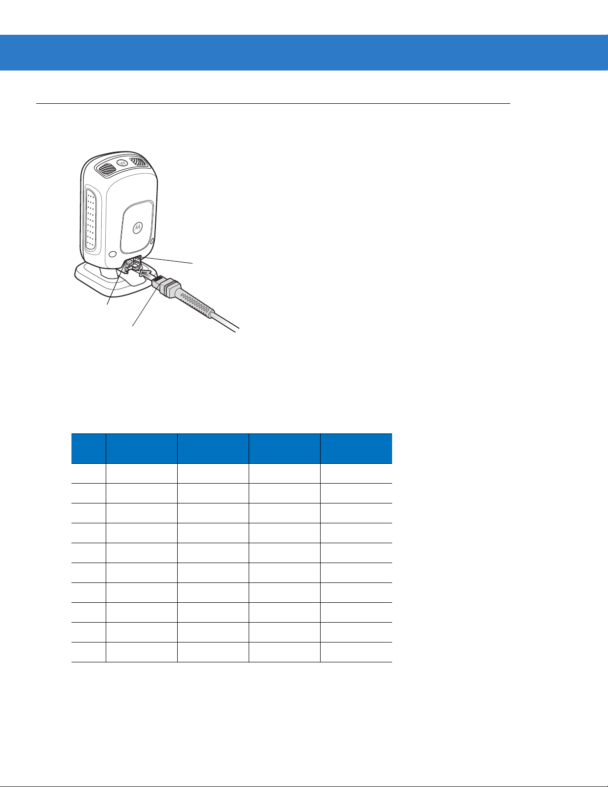
Digital Scanner Signal Descriptions
Pin 1
Pin 10
Interface cable
modular connector
Maintenance & Technical Specifications 3 - 7
Figure 3-1
The signal descriptions in Table 3-3 apply to the connectors on the DS9208 digital scanner and are for reference
only .
Table 3-3
Pin IBM RS-232
1
2
3
4
5
6
7
8
9
10
Digital Scanner Cable Pinouts
DS9208 Digital Scanner Signal Pin-outs
Keyboard
Wedge
Reserved Reserved Reserved Jump to Pin 6
Power Power Power Power
Ground Ground Ground Ground
IBM_A(+) TxD KeyClock Reserved
Reserved RxD TermData D +
IBM_B(-) RTS KeyData Jump to Pin 1
Reserved CTS TermClock D Reserved Reserved Reserved Reserved
Reserved Reserved Reserved Reserved
Reserved Reserved Reserved Reserved
USB
Page 44

3 - 8 DS9208 Product Reference Guide
Page 45

Chapter 4 User Preferences & Miscellaneous
*High Volume
(00h)
Feature/Option
* Indicates Default
Option Hex Value
Digital Scanner Options
Introduction
You can program the digital scanner to perform various functions, or activate different features. This chapter
describes each user preference feature and provides programming bar codes for selecting these features.
The digital scanner ships with the settings shown in T able 4-1 on page 4-2 (also see Appendix A, Standard Default
Parameters for all host device and miscellaneous defaults). If the default values suit requirements, programming is
not necessary.
To set feature values, scan a single bar code or a short bar code sequence. The settings are stored in non-volatile
memory and are preserved even when the digital scanner is powered down.
NOTE Most computer monitors allow scanning the bar codes directly on the screen (when using the imaging
engine). When scanning from the screen, be sure to set the document magnification to a level where you
can see the bar code clearly, and bars and/or spaces are not merging.
If not using a USB cable, select a host type (see each host chapter for specific host information) after the power-up
beeps sound. This is only necessary upon the first power-up when connected to a new host.
To return all features to default values, scan the Set Default Parameter on page 4-4. Throughout the programming
bar code menus, asterisks indicate (
*) default values.
Page 46
4 - 2 DS9208 Product Reference Guide
Scanning Sequence Examples
In most cases, scanning one bar code sets the parameter value. For example, to set the beeper tone to high, scan
the High Frequency (beeper tone) bar code listed under Beeper Tone on page 4-6. The digital scanner issues a
fast warble beep and the LED turns green, signifying a successful parameter entry.
Other parameters, such as Serial Response Time-Out or Data Transmission Formats, require scanning several
bar codes. See these parameter descriptions for this procedure.
Errors While Scanning
Unless otherwise specified, to correct an error during a scanning sequence, just re-scan the correct parameter.
User Preferences/Miscellaneous Options Parameter Defaults
Table 4-1 lists defaults for user preferences parameters. To change the default values, scan the appropriate bar
codes in this guide. These new values replace the standard default values in memory . To recall the default
parameter values, scan the Set Default Parameter on page 4-4.
NOTE See Appendix A, Standard Default Parameters for all user preferences, hosts, symbologies, and
miscellaneous def aul t pa r am ete rs.
Table 4-1
User Preferences
Set Default Parameter Set Defaults 4-4
Parameter Bar Code Scanning ECh Enable 4-5
Beep After Good Decode 38h Enable 4-5
Beeper Tone 91h Medium 4-6
Beeper Volume 8Ch High 4-7
Volume Adjustment Trigger Timeout F0h 93h 5.0 Sec 4-8
Beeper Duration F1h 74h Medium 4-9
Suppress Power-up Beeps F1h D1h Do not suppress 4-9
Low Power Mode 80h Disable 4-10
User Preferences Parameter Defaults
Parameter
Parameter
Number
Default
Page
Number
Time Delay to Low Power Mode 92h 1 Hour 4-11
Trigger Mode 8Ah Presentation 4-13
Trigger Aiming Pattern F0h 32h Enable 4-14
Presentation Aiming Pattern F1h 4Eh Disable 4-15
Page 47

User Preferences & Miscellaneous Digital Scanner Options 4 - 3
Table 4-1
Momentary Trigger Mode Timeout EDh 5 sec 4-16
Motion Detect Range F2h 3Bh Full 4-17
Post Decode Illumination F2h 29h Always Off 4-18
Presentation Mode Field of View F1h 61h Full 4-18
Picklist Mode F0h 92h Enabled in Trigger Mode 4-19
Continuous Bar Code Read F1h 89h Disable 4-20
Unique Bar Code Reporting F1h D31h Disable 4-20
Decode Session Timeout 88h 9.9 Sec 4-21
Timeout Between Decodes, Same Symbol 89h 0.5 Sec 4-21
Timeout Between Decodes, Different Symbols 90h 0.2 Sec 4-22
Fuzzy 1D Processing F1h 02h Enable 4-22
Decode Mirror Images F1h, 19h Auto 4-23
Mobile Phone/Display Mode F1h CCh Enable in Both
User Preferences Parameter Defaults (Continued)
Parameter
Parameter
Number
Default
4-24
Hand-Held and
Hands-Free Modes
Page
Number
PDF Prioritization F1h CFh Disable 4-25
PDF Prioritization Timeout F1h D0h 200 ms 4-25
Decoding Illumination (Hand-Held Mode Only) F0h, 2Ah Enable 4-26
Multicode Mode F1h, A5h Disable 4-27
Multicode Expression F1h, 95h 1 4-28
Multicode Mode Concatenation F1h, CDh Disable 4-33
Multicode Concatenation Symbology F1h, D2h Concatenate as PDF417 4-34
Miscellaneous Options
Transmit Code ID Character 2Dh None 4-37
Prefix Value 63h, 69h 7013 <CR><LF> 4-38
Suffix 1 V alue
Suffix 2 V alue
Scan Data Transmission Format EBh Data as is 4-39
FN1 Substitution Values 67h 6Dh Set 4-41
Transmit “No Read” Message 5Eh Disable 4-42
62h 68h
64h 6Ah
7013 <CR><LF> 4-38
Page 48

4 - 4 DS9208 Product Reference Guide
User Preferences
Set Default Parameter
Y ou can reset the digital scanner to two types of defaults: factory defaults or custom defaults. Scan the appropriate
bar code below to reset the digital scanner to its default settings and/or set its current settings as custom defaults.
•
Set Defaults - Scan this bar code to reset all default parameters as follows.
• If you previously set custom defaults by scanning Write to Custom Defaults, scan Set Defaults to
retrieve and restore the digital scanner’s custom default settings.
• If you did not set custom defaults, scan Set Defaults to restore the factory default values listed in Table
A-1.
•
Set Factory Defaults - Scan this bar code to restore the factory default values listed in Table A-1. This
deletes any custom defaults set.
•
Write to Custom Defaults - Scan this bar code to set the current digital scanner settings as custom defaults.
Once set, you can recover custom default settings by scanning Set Defaults.
*Set Defaults
Write to Custom Defaults
Set Factory Defaults
Page 49

User Preferences & Miscellaneous Digital Scanner Options 4 - 5
Parameter Bar Code Scanning
Parameter # ECh
To disable the decoding of parameter bar codes, including the Set Defaults parameter bar codes, scan the
Disable Parameter Scanning bar code below. To enable decoding of parameter bar codes, scan Enable
Parameter Scanning.
*Enable Parameter Bar Code Scanning
(01h)
Disable Parameter Bar Code Scanning
(00h)
Beep After Good Decode
Parameter # 38h
Scan a bar code below to select whether or not the digital scanner beeps after a good decode. If selecting Do Not
Beep After Good Decode, the beeper still operates during parameter menu scanning and to indicate error
conditions.
*Beep After Good Decode
(Enable)
(01h)
Do Not Beep After Good Decode
(Disable)
(00h)
Page 50

4 - 6 DS9208 Product Reference Guide
Beeper Tone
Parameter # 91h
To select a decode beep frequency (tone), scan one of the following bar codes.
Off
(03h)
Low Tone
(02h)
*Medium Tone
(01h)
Medium to High Tone (2-tone)
(04h)
High To ne
(00h)
Page 51

User Preferences & Miscellaneous Digital Scanner Options 4 - 7
Beeper Volume
Parameter # 8Ch
To select a beeper volume, scan the Low Volume, Medium Volume, or High Volume bar code.
Low Volume
(02h)
Medium Volume
(01h)
*High Volume
(00h)
Page 52

4 - 8 DS9208 Product Reference Guide
Volume Adjustment Trigger Timeout
Parameter # F0h 93h
Use this parameter to set the length of time needed to hold the trigger to adjust the volume. The scanner changes
volume and beeps with the new volume.
Volume Adjustment Trigger Timeout 3 sec
(1Eh)
*Volume Adjustment Trigger Timeout 5 sec
(32h)
Volume Adjustment Trigger Timeout 7 sec
(46h)
Page 53

User Preferences & Miscellaneous Digital Scanner Options 4 - 9
Beeper Duration
Parameter # F1h 74h
To select the duration for the beeper, scan one of the following bar codes.
Short
(00h)
* Medium
(01h)
Long
(02h)
Suppress Power-up Beeps
Parameter # F1h D1h
Select whether or not to suppress the digital scanner’s power-up beeps.
Suppress Power-up Beeps
(01h)
* Do Not Suppress Power-up Beeps
(00h)
Page 54

4 - 10 DS9208 Product Reference Guide
Low Power Mode
Parameter # 80h
This parameter determines whether or not the digital scanner enters low power mode after a decode attempt.
If disabled, power remains on after each decode attempt.
*Disable Low Power Mode
(00h)
Enable Low Power Mode
(01h)
Page 55

User Preferences & Miscellaneous Digital Scanner Options 4 - 11
Time Delay to Low Power Mode
Parameter # 92h
NOTE This parameter only applies when Low Power Mode is enabled.
This parameter sets the time the digital scanner remains active before entering low power mode. The digital
scanner wakes upon trigger pull or when the host attempts to communicate with the digital scanner.
1 Second
(11h)
1 Minute
(21h)
15 Minutes
(2Bh)
10 Seconds
(1Ah)
5 Minutes
(25h)
Page 56

4 - 12 DS9208 Product Reference Guide
Time Delay to Low Power Mode (continued)
30 Minutes
(2Dh)
45 Minutes
(2Eh)
*1 Hour
(31h)
6 Hours
(36h)
3 Hours
(33h)
9 Hours
(39h)
Page 57

User Preferences & Miscellaneous Digital Scanner Options 4 - 13
Trigger Mode
Parameter # 8Ah
Select one of the following trigger modes for the digital scanner:
•
Standard (Level) - A trigger pull activates decode processing. Decode processing continues until the bar
code decodes, you release the trigger, or the Decode Session Timeout occurs.
•
Presentation - The digital scanner activates decode processing when it detects a bar code in its field of view.
After a period of non-use, the digital scanner enters a low power mode, in which the LEDs turn off until the
digital scanner senses motion.
•
Auto Aim - This trigger mode turns on the LED aiming dot when you lift the digital scanner. A trigger pull
activates decode processing. After 2 seconds of inactivity the aiming dot shuts off.
Standard (Level)
(00h)
Auto Aim
(09h)
*Presentation
(07h)
Page 58
4 - 14 DS9208 Product Reference Guide
Trigger Aiming Pattern
Parameter # F0h, 32h
Select Enable Trigger Aiming Pattern to project the aiming pattern during bar code capture in trigger mode, or
Disable Trigger Aiming Pattern to turn the aiming pattern off.
This parameter does not apply to Snapshot Mode. See Operational Modes on page 5-4.
NOTE With Picklist Mode on page 4-19 enabled, the decode aiming pattern flashes even when the Decode
Aiming Pattern is disabled.
*Enable Trigger Aiming Pattern
(02h)
Disable Trigger Aiming Pattern
(00h)
Page 59

User Preferences & Miscellaneous Digital Scanner Options 4 - 15
Presentation Aiming Pattern
Parameter # F1h, 4Eh
Select Enable Presentation Aiming Pattern to project the aiming pattern during bar code capture in presentation
mode, Disable Presentation Aiming Pattern to turn the aiming pattern off, or Enable Presentation Aiming
Pattern on PDF to project the aiming pattern when the digital scanner detects a 2D bar code.
This parameter does not apply to Snapshot Mode. See Operational Modes on page 5-4.
NOTE With Picklist Mode on page 4-19 enabled, the decode aiming pattern flashes even when the Decode
Aiming Pattern is disabled.
Enable Presentation Aiming Pattern
(01h)
Enable Presentation Aiming Pattern on PDF
(02h)
*Disable Presentation Aiming Pattern
(00h)
Page 60
4 - 16 DS9208 Product Reference Guide
Momentary Trigger Mode Timeout
Parameter # EDh
In momentary trigger mode, the aiming dot appears upon pressing the trigger. Once in this mode, upon each
trigger press the scanner attempts to decode the bar code in front of it. After a period of inactivity while the trigger
is not pressed, the scanner reverts to presentation mode where there is no illumination until an item is presented.
This parameter controls the length of the period of inactivity in momentary trigger mode before the scanner reverts
to presentation mode.
Momentary Trigger Mode Timeout - 2 Seconds
(14h)
Momentary Trigger Mode Timeout - 4 Seconds
(28h)
Momentary Trigger Mode Timeout - 3 Seconds
(1Eh)
*Momentary Trigger Mode Timeout - 5 Seconds
(32h)
Page 61
User Preferences & Miscellaneous Digital Scanner Options 4 - 17
Motion Detect Range
Parameter # F2h 3Bh
This parameter controls the distance, or range, at which the scanner detects object motion and then triggers while
in Presentation Mode.
*Full Range
(01h)
Medium Range
(03h)
Short Range
(08h)
Page 62

4 - 18 DS9208 Product Reference Guide
Post Decode Illumination
Parameter # F2h 29h
This parameter controls illumination after decode. Select Always Off to turn off illumination immediately after
decode. Select
illumination on until timeout.
Always On to keep Illumination on after decode so the scanner is ready for next decode, or to keep
Always On
(00h)
*Always Off
(01h)
Presentation Mode Field of View
Parameter # F1h 61h
In presentation mode, by default the digital scanner searches the larger area of the aiming pattern (Full Field of
View
).
To search for a bar code in a smaller region around the aiming pattern’s center cross in order to speed search time,
select
Small Field of View or Medium Field of View.
Small Field of View
(00h)
Medium Field of View
(01h)
*Full Field of View
(02h)
Page 63
User Preferences & Miscellaneous Digital Scanner Options 4 - 19
Picklist Mode
Parameter # F0h 92h
Picklist mode enables the digital scanner to decode only the bar code targeted by the aiming dot. Select one of the
following picklist modes for the digital scanner:
•
Disabled - Picklist mode is always disabled.
•
Enabled in Trigger Mode - Picklist mode is enabled when the digital scanner is out of trigger mode and
disabled when the digital scanner is in presentation mode.
•
Enabled Always - Picklist mode is always enabled.
NOTE Picklist mode functi ons optimal ly when bar codes are vertic ally spa ced a mi nimum of 1 5 mm edge to edge.
Disabled
(00h)
Enabled Always
(02h)
*Enabled in Trigger Mode
(01h)
Page 64

4 - 20 DS9208 Product Reference Guide
Continuous Bar Code Read
Parameter # F1h 89h
Enable this to report every bar code while the trigger is pressed.
NOTE Motorola strongly recommends enabling Picklist Mode with this feature. Disabling Picklist Mode can
cause accidental decodes when more than one bar code is in the imaging engine's field of view.
*Disable Continuous Bar Code Read
(00h)
Enable Continuous Bar Code Read
(01h)
Unique Bar Code Reporting
Parameter # F1h D3h
Enable this to report only unique bar codes while the trigger is pressed. This option only applies when Continuous
Bar Code Read
is enabled.
*Disable Continuous Bar Code Read Uniqueness
(00h)
Enable Continuous Bar Code Read Uniqueness
(01h)
Page 65

User Preferences & Miscellaneous Digital Scanner Options 4 - 21
Decode Session Timeout
Parameter # 88h
This parameter sets the maximum time decode processing continues during a scan attempt. It is programmable in
0.1 second increments from 0.5 to 9.9 seconds. The default timeout is 9.9 seconds.
To set a Decode Session Timeout, scan the bar code below. Next, scan two numeric bar codes from Appendi x D,
Numeric Bar Codes that correspond to the desired on time. Enter a leading zero for single digit numbers. For
example, to set a Decode Session Timeout of 0.5 seconds, scan the bar code below, then scan the 0 and 5 bar
codes. To correct an error or change the selection, scan Cancel on page D-2.
NOTE The Decode Session Timeout cannot be less than or equal to either Timeout Between Decodes, Same
Symbol or Timeout Between Decodes, Different Symbols.
Decode Session Timeout
Timeout Between Decodes, Same Symbol
Parameter # 89h
Use this option in presentation mode and Continuous Bar Code Read to prevent the beeper from continuously
beeping when a symbol is left in the digital scanner’s field of view. It is programmable in 0.1 second increments
from 0.0 to 9.9 seconds. The default interval is 0.5 seconds.
To select the timeout between decodes for the same symbol, scan the bar code below, then scan two numeric bar
codes from Appendix D, Numeric Bar Codes that correspond to the desired interval, in 0.1 second increments.
NOTE The Timeout between Decodes, Same Symbol cannot be greater than or equal to the Decode Session
Timeout.
Timeout Between Decodes, Same Symbol
Page 66

4 - 22 DS9208 Product Reference Guide
Timeout Between Decodes, Different Symbols
Parameter # 90h
Use this option in presentation mode and Continuous Bar Code Read to control the time the scanner is inactive
between decoding different symbols. It is programmable in 0.1 second increments from 0.1 to 9.9 seconds. The
default is 0.2 seconds.
To select the timeout between decodes for different symbols, scan the bar code below, then scan two numeric bar
codes from Appendix D, Numeric Bar Codes that correspond to the desired interval, in 0.1 second increments.
NOTE The Timeout between Decodes, Different Symbols cannot be greater than or equal to the Decode
Session Timeout.
Timeout Between Decodes, Different Symbols
Fuzzy 1D Processing
Parameter # F1h 02h
This option is enabled by default to optimize decode performance on 1D bar codes, including damaged and poor
quality symbols. Disable this only if you experience time delays when decoding 2D bar codes, or in detecting a no
decode.
*Enable Fuzzy 1D Processing
(01h)
Disable Fuzzy 1D Processing
(00h)
Page 67

User Preferences & Miscellaneous Digital Scanner Options 4 - 23
Decode Mirror Images (Data Matrix Only)
Parameter # F1h 19h
Select an option for decoding mirror image Data Matrix bar codes:
•
Always - decode only Data Matrix bar codes that are mirror images
•
Never - do not decode Data Matrix bar codes that are mirror images
•
Auto - decode both mirrored and unmirrored Data Matrix bar codes.
Never
(00h)
*Auto
(02h)
Always
(01h)
Page 68

4 - 24 DS9208 Product Reference Guide
Mobile Phone/Display Mode
Parameter # F1h CCh
This mode improves bar code reading performance on mobile phones and electronic displays. Enable this in
hand-held, hands-free, or both modes, or disable this.
NOTE If you enable this mode, for best performance also enable Presentation Aiming Pattern on page 4-15.
Disable Mobile Phone/Display Mode
(00h)
Enable in Hands-Free Mode
(02h)
Enable in Hand-Held Mode
(01h)
*Enable in Both Modes
(03h)
Page 69

User Preferences & Miscellaneous Digital Scanner Options 4 - 25
PDF Prioritization
Parameter # F1h CFh
Enable this feature to delay decoding a 1D bar code (Code 128 of 8 to 25 characters length) by the value specified
in PDF Prioritization Timeout. During that time the digital scanner attempts to decode a PDF417 symbol (e.g., on a
US driver's license), and if successful reports this only. If it does not decode (can not find) a PDF417 symbol, it
reports the 1D symbol after the timeout. The 1D symbol must be in the device’s field of view for the digital scanner
to report it. This parameter does not affect decoding other symbologies.
NOTE Disable Picklist Mode on page 4-19 if enabling this parameter.
*Disable PDF Prioritization
(00h)
Enable PDF Prioritization
(01h)
PDF Prioritization Timeout
Parameter # F1h D0h
When PDF Prioritization is enabled, this timeout specifies how long the digital scanner attempts to decode a
PDF417 symbol before reporting the 1D bar code in the field of view.
Scan the following bar code, then scan four digits from Appendix D, Numeric Bar Codes that specify the timeout in
milliseconds. For example, to enter 400 ms, scan the following bar code, then scan 0400. The range is 0 to 5000
ms, and the default is 200 ms.
PDF Prioritization Timeout
Page 70

4 - 26 DS9208 Product Reference Guide
Decoding Illumination (Hand-Held Mode Only)
Parameter # F0h, 2Ah
When in hand-held mode, selecting Enable Decoding Illumination causes the digital scanner to flash illumination
to aid decoding. Select Disable Decoding Illumination to prevent the digital scanner from using decoding
illumination.
Enabling illumination usually results in superior images. The effectiveness of the illumination decreases as the
distance to the target increases.
*Enable Decoding Illumination
(01h)
Disable Decoding Illumination
(00h)
Page 71

User Preferences & Miscellaneous Digital Scanner Options 4 - 27
Multicode Mode
Parameter # F1h, A5h
Enable this parameter to allow multiple bar codes to decode upon one trigger event based on the programmed
multicode expression. The digital scanner reports a successful decode and provides user indication only if it
decodes all bar codes indicated by the multicode expression, otherwise the decode fails. Bar codes are transmitted
in the order defined in the multicode expression. Disable this to operate in normal decode mode.
NOTES Enabling Multicode Mode disables Picklist Mode.
Multicode does not operate in presen t ati on mode.
Do not use Multicode Mode if a trigger is set to Laser Preferred Decoding.
Do not use Multicode Mode if Continuous Bar C ode Read is enabled.
When using this mode, always orient the digital scanner at the same distance and angle (perpendicular).
*Disable Multicode Mode
(00h)
Enable Multicode Mode
(01h)
Page 72

4 - 28 DS9208 Product Reference Guide
Multicode Expression
Parameter # F1h, 95h
Use this feature to program a multicode expression for Multicode Mode (grid method). The default is 1, which
indicates any bar code.
To set the multicode expression:
1. Scan the bar code below.
2. Scan bar codes from the alphanumeric keyboard in the Adva nc ed Data Formatti ng Prog ra mme r Guide to
define the expression.
3. Scan the End of Message bar code from the Advanced Data Formatting Programmer Guide.
Multicode Expression
Multicode Expression Syntax: [n] [Element 1]; [Element 2 ]; ... [Element n];
Where n is the number of elements in the overall expression.
The multicode expression describes the bar code(s) that the digital scanner can expect to find in an image. Each
element represents one bar code in the digital scanner's field of view. The order of elements in the expression is
the order in which bar code data from each element transmits to the host. Elements are defined using one or more
of the following methods:
By Region. This type of element limits decoding to a specific area within the digital scanner's field of view. Region
coordinates are defined as the top left and bottom right corners of the region, expressed in percentages of the field
of view. These can range from 0% to 100%, or 0x00 to 0x64 in hex, for both horizontal and vertical axes. A region
element is constructed as:
[R] [4] [Top, Left] [Bottom, Right]
Where:
•
[R] is the character R
•
[4] is 0x04, indicating there are four bytes thereafter to describe the region
•
[Top, Left] are two values representing the top left corner of the region
•
[Bottom, Right] are two values representing the bottom right corner of the region
By Code Type. An element can specify a specific bar code symbology to find and decode somewhere in the field of
view. A code type element is constructed as:
[C] [2] [Code Type]
Where:
•
[C] is the character C
•
[2] is 0x02, indicating there are two bytes thereafter to describe the code type
•
[Code Type] is the desired symbology's parameter number (see Chapter 10, Symbologies). For single-byte
parameter numbers, extend the value to two bytes by adding 00 before the parameter number.
Page 73

User Preferences & Miscellaneous Digital Scanner Options 4 - 29
Notes
When defining multicode expressions consider the following:
•
Use the Code Type specifier if there are bar codes of more than one code type in view.
•
Always use the Region specifier when there are multiple bar codes of the same code type.
•
When transmission order is important (the first element in the expression transmits first), use either type to
define the order.
•
When there are unwanted bar codes in view, filter them out in one of two ways:
• Use Code Type to specify only the target bar codes.
• Use Region to identify only the target bar codes.
•
If the expression does not contain a Region specifier, scanning angle and distance do not matter. If you
specify a region you must scan in a fixed orientation and at a fixed distance. Because of this, it is preferable
to use the Code Type specifier rather than the Region specifier.
•
When defining regions:
• Defining a region much larger than the bar code improves tolerance to scan distance and angle, but can
cause a decode of a nearby bar code instead of the target bar code. Therefore, for best performance
define larger regions when only a few bar codes are in view and those in view are widely separated.
• Defining a region close to (or smaller than) the target bar code improves the probability of decoding this
bar code rather than one nearby, but scan distance and angle must be more accurate. Therefore, for best
performance define small regions when many bar codes are in view or those in view are close together.
•
Use Region elements to improve decode speeds by reducing the image area to search for the target bar
code.
•
Specifying Code Type may also improve decode speeds for some code types.
•
Although you can scan parameter bar codes when multicode mode is enabled, be aware of the following: If
the multicode expression defined a region(s), to scan a parameter bar code you must position the bar code
within the first region defined in the expression. In some cases, this first region is not the center of the image
and aiming at the parameter bar code does not result in a successful decode.
The following examples show the multicode expressions in both hex and decimal formats, however in the sample
figures the values are decimal. Be sure to use the correct base numbering system when creating an expression. A
region specified as 0x00 0x00 0x64 0x32 represents a region with coordinates of T op-Left (0,0) and Bottom Right
(100,50).
Page 74
4 - 30 DS9208 Product Reference Guide
12
4
7
9
50%
0%
100%
0%
50%
100%
PDF417 Code
Code 128 Code
UPC-A Code
Example 1
To decode one Code 128 bar code anywhere in the image (even when bar codes of other types are in view), as in
Figure 4-1, program the expression as follows:
The expression in decimal is (formatted for readability):
1 C 2 0 8 ;
To program the expression via scanning parameters the sequence is (spaces are for readability):
[MultiCode-Expression] 01 C 02 00 08 ; [End Of Message]
To program the expression via host command (SSI/SNAPI) the sequence is:
0x01 0x43 0x02 0x00 0x08 0x3b
Figure 4-1
Multicode Expression Example 1
Page 75
User Preferences & Miscellaneous Digital Scanner Options 4 - 31
PDF417 Code
(0,0)
Code 128 Code
(0,50)
(160,100)
(100,50)
50%
0%
100%
0%
50%
100%
Example 2a
To decode a Code128 (Code Type=8) on the top half of the image and a PDF417 (Code Type=15) on the bottom
half of the image, as in Figure 4-2, program the expression as follows:
The expression in decimal is (formatted for readability):
2 C 2 0 8 R 4 0 0 100 50 ; C 2 0 15 R 4 0 50 100 100 ;
To program the expression via scanning parameters the sequence is:
[MultiCode-Expression] 02 C 02 00 08 R 04 00 00 64 32 ; C 02 00 0F R 04 00 32 64 64 ; [End Of Message]
To program the expression via host command (SSI/SNAPI) the sequence is:
0x02 0x43 0x02 0x00 0x08 0x52 0x04 0x00 0x00 0x64 0x32 0x3B 0x43 0x02 0x00 0x0F 0x52 0x04 0x00 0x32
0x64 0x64 0x3B
Example 2b
In Figure 4-2, if the bottom PDF417 bar code must transmit first, reverse the sequence of the two bar codes:
The expression in decimal is (formatted for readability):
2 C 2 0 15 R 4 0 50 100 100 ; C 2 0 8 R 4 0 0 100 50 ;
To program the expression via scanning parameters the sequence is:
[MultiCode-Expression] 02 C 02 00 0F R 04 00 32 64 64 ; C 02 00 08 R 04 00 00 64 32 ; [End Of Message]
To program the expression via host command (SSI/SNAPI) the sequence is:
0x02 0x43 0x02 0x00 0x0F 0x52 0x04 0x00 0x32 0x64 0x64 0x3B 0x43 0x02 0x00 0x08 0x52 0x04 0x00 0x00
0x64 0x32 0x3B
Figure 4-2
Multicode Expression Example 2
Page 76

4 - 32 DS9208 Product Reference Guide
40%
65%
40%
40%
PDF417 Code
Code 128 Code
Data Matrix Code
Code 128 Code
70%
60%
(70,0)
(100,40)
(100,100)
(0,0)
(40,40)
(65,60)
50%
0%
100%
0% 50% 100%
Example 3
To decode the set of three bar codes while excluding the center Code 128 bar code, as in Figure 4-3, the
expression is:
The expression in decimal is (formatted for readability):
3 C 2 0 15 R 4 0 0 50 50 ; C 2 [F0 24] R 4 70 0 100 40 ; C 2 0 8 R 4 65 60 100 100 ;
To program the expression via scanning parameters the sequence is:
[MultiCode-Expression] 03 C 02 00 0F R 04 00 00 32 32 ; C 02 F0 24 R 04 46 00 64 28 ;
C 02 00 08 R 04 41 3C 64 64 ; [End Of Message]
To program the expression via host command (SSI/SNAPI) the sequence is:
0x03 0x43 0x02 0x00 0x0F 0x52 0x04 0x00 0x00 0x32 0x32 0x3B 0x43 0x02 0xF0 0x24 0x52 0x04 0x46 0x00
0x64 0x28 0x3B 0x43 0x02 0x00 0x08 0x52 0x04 0x41 0x3C 0x64 0x64 0x3B
Figure 4-3
Multicode Expression Example 3
Page 77
User Preferences & Miscellaneous Digital Scanner Options 4 - 33
Multicode Mode Concatenation
Parameter # F1h, CDh
Enable this parameter to transmit multiple decoded bar codes, as specified by the Multicode Expression, as one
bar code. Use the Multicode Concatenation Symbology parameter to specify how the concatenated bar codes
transmit.
Disable this to transmit decoded bar codes separately.
NOTE When using Multicode Mod e Conca tenatio n, dis able Transmit Code ID Character on page 4-37 and check
digits.
Enable Multicode Mode Concatenation
(01h)
*Disable Multicode Mode Concatenation
(00h)
Page 78
4 - 34 DS9208 Product Reference Guide
Multicode Concatenation Symbology
Parameter # F1h, D2h
Use this parameter to specify how to transmit the concatenated bar codes decoded as specified by the Multicode
Expression. Multic ode Mod e Conca ten ati on must be enabled to use this option.
Concatenation as Code 128
(01h)
*Concatenation as PDF417
(02h)
Concatenation as Data Matrix
(03h)
Concatenation as Maxicode
(04h)
Page 79

User Preferences & Miscellaneous Digital Scanner Options 4 - 35
Multicode Troubleshooting
Troubleshooting Multicode Expression Programming
Use the following suggestions if encountering problems programming a multicode expression:
•
Ensure the expression is valid. Invalid expressions are rejected during programming. When an expression is
rejected the previous expression remains intact. If after programming the expression the digital scanner can
still decode any bar code, the expression was possibly rejected.
•
When programming the multicode expression via parameter bar code, the digital scanner generates beeps. If
any of the following beeps do not sound during programming, an error occurred (see Table 2-1 on page 2-2
and Table 2-2 on page 2-4 for error indicators):
• Scanning the
• Scanning each value of the expression produces a two-tone (same pitch) beep.
• Scanning the
•
Check the expression for syntax errors.
•
Try programming a simple expression to ensure the syntax is correct. See Examples of Simple Multicode
Expressions.
Multicode Expression bar code produces a two-tone (same pitch) beep.
End Of Message bar code produces a four-tone (high-low-high-low) beep.
•
Review Notes on page 4-29 for additional hi nts.
Troubleshooting Multicode Mode Scanning and Decoding
Use the following suggestions if encountering problems using multicode mode:
•
If the digital scanner appears to decode any single bar code instead of the intended multiple bar codes,
ensure you enabled Multicode Mode on page 4-27. Programming the multicode expression does not enable
multicode mode.
•
When specifying Region, ensure:
• Coordinates are within range the 0-100 decimal (or 0x00 - 0x64 hexadecimal).
• Top, Left is above Bottom, Right. Top, Left is 0,0 (0x00, 0x00 hexadecimal), and Bottom, Right is 100,100
(0x64, 0x64 hexadecimal).
• Regions for two or more bar codes do not overlap.
•
When specifying Code Type ensure the digital scanner supports the code type. Try decoding a single bar
code without using multicode. If it does not decode try enabling the bar code type. See Chapter 10,
Symbologies.
•
Experiment with simpler expressions, then add to it until you discover the source of the error. For example try
the simplest expression (see Examples of Simple Multicode Expressions) and make sure you can scan a
single bar code. If so, extend the expression by adding a second bar code, specifying a region, or specifying
the code type. Verify that the digital scanner can decode this new expression. Continue adding to the
expression until it fails to decode as expected, indicating the source of the error.
•
Review Notes on page 4-29 for additional hi nts.
Page 80

4 - 36 DS9208 Product Reference Guide
Examples of Simple Multicode Expressions
The simplest multicode expression is:
•
One bar code of any type, anywhere in the image.
•
To program this use: [MultiCode-Expression] 01 ; [End Of Message]
Another simple multicode expression is:
•
One Code 128 bar code, anywhere in the image.
•
To program this use: [MultiCode-Expression] 01 C 02 00 08 ; [End Of Message]
Page 81

User Preferences & Miscellaneous Digital Scanner Options 4 - 37
Miscellaneous Scanner Parameters
Transmit Code ID Character
Parameter # 2Dh
A Code ID character identifies the code type of a scanned bar code. This is useful when decoding more than one
code type. In addition to any single character prefix already selected, the Code ID character is inserted between
the prefix and the decoded symbol.
Select no Code ID character, a Symbol Code ID character, or an AIM Code ID character. For Code ID Characters,
see Symbol Code Identifiers on page B-1 and AIM Code Identifiers on page B-3.
NOTE If you enable Symbol Code ID Character or AIM Code ID Character, and enable Tr an sm it “No Read”
Message on page 4-42, the digital scanner appends the code ID for Code 39 to the NR message.
Symbol Code ID Character
(02h)
*None
(00h)
AIM Code ID Character
(01h)
Page 82
4 - 38 DS9208 Product Reference Guide
Prefix/Suffix Values
Key Category Parameter # P = 63h, S1 = 62h, S2 = 64h
Decimal Value Parameter # P = 69h, S1 = 68h, S2 = 6Ah
Y ou can append a prefix and/or one or two suffixes to scan data for use in data editing. T o set a value for a prefix or
suffix, scan a four-digit number (i.e., four bar codes from Appendix D, Numeric Bar Codes) that corresponds to that
value. See Table E-1 on page E-1 for the four-digit codes.
When using host commands to set the prefix or suffix, set the key category parameter to 1, then set the 3-digit
decimal value. See Table E-1 on page E-1 for the four-digit codes.
To correct an error or change a selection, scan Cancel on page D-2.
NOTE To use Prefix/Suffix values, first set the Scan Data Transmission Format on page 4-39.
Scan Prefix
(07h)
Scan Suffix 2
(08h)
Scan Suffix 1
(06h)
Data Format Cancel
Page 83

User Preferences & Miscellaneous Digital Scanner Options 4 - 39
Scan Data Transmission Format
Parameter # EBh
To change the scan data format, scan the Scan Options bar code, then scan one of eight bar codes corresponding
to the desired format, and then the Enter bar code.
To correct a mistake, scan the Data Format Cancel bar code.
NOTE If using this parameter do not use ADF rules to set the prefix/suffix.
To set values for the prefix and/or suffix, see Prefix/Suffix Values on page 4-38.
Scan Options
<DATA> <SUFFIX 1>
(01h)
*Data As Is
(00h)
<DATA> <SUFFIX 2>
(02h)
Page 84

4 - 40 DS9208 Product Reference Guide
Scan Data Transmission Format (continued)
<DATA> <SUFFIX 1> <SUFFIX 2>
(03h)
<PREFIX> <DATA >
(04h)
<PREFIX> <DATA> <SUFFIX 1>
(05h)
<PREFIX> <DATA> <SUFFIX 1> <SUFFIX 2>
(07h)
<PREFIX> <DATA> <SUFFIX 2>
(06h)
Enter
Data Format Cancel
Page 85

User Preferences & Miscellaneous Digital Scanner Options 4 - 41
FN1 Substitution Values
Key Category Parameter # 67h
Decimal Value Parameter # 6Dh
The wedge and USB HID keyboard hosts support a FN1 Substitution feature. Enabling this substitutes any FN1
character (0x1b) in an EAN128 bar code with a value. This value defaults to 7013 (Enter key).
When using host commands to set the FN1 substitution value, set the key category parameter to 1, then set the
3-digit keystroke value. See the ASCII character set table for the current host interface for the desired value.
To select a FN1 substitution value via bar code menus:
1. Scan the bar code below.
Set FN1 Substitution Value
2. Locate the keystroke desired for FN1 substitution in the ASCII character set table in the appropriate host
interface chapter. Enter the 4-digit ASCII value by scanning each digit in Appendix D, Numeric Bar Codes.
To correct an error or change the selection, scan Cancel on page D-2.
See USB Keyboard FN 1 Substitution on page 6-13 to enable FN1 substitution for the USB HID keyboard.
Page 86

4 - 42 DS9208 Product Reference Guide
Transmit “No Read” Message
Parameter # 5Eh
Scan a bar code below to select whether or not to transmit a No Read message. Enable this to transmit the
characters NR when a successful decode does not occur before trigger release or the
expires. See Decode Session Timeout on page 4-21. Disable this to send nothing to the host if a symbol does not
decode.
NOTE If you enable Transmit No Read, and also enable Symbol Code ID Character or AIM Code ID Character
for Transmit Code ID Character on page 4-37, the digital scanne r appends the code ID for Code 39 to th e
NR message.
Enable No Read
(01h)
Decode Session Timeout
*Disable No Read
(00h)
Page 87

Chapter 5 Imaging Preferences
Feature/Option
* Indicates Default
*Enable Decode Aiming Pattern
(02h)
Option Hex Value
Introduction
You can program the digital scanner to perform various functions, or activate different features. This chapter
describes imaging preference features and provides programming bar codes for selecting these features.
NOTE Only the Symbol Native API (SNAPI) with Imaging interface supports image capture. See USB Device
Type on page 6-4 to enable this host.
The digital scanner ships with the settings in Imaging Preferences Parameter Defaults on page 5-2 (also see
Appendix A, Standard Default Parameters for all host device and miscellaneous defaults). If the default values suit
requirements, programming is not necessary.
To set feature values, scan a single bar code or a short bar code sequence. The settings are stored in non-volatile
memory and are preserved even when you power down the digital scanner.
NOTE Most computer monitors allow scanning the bar codes directly on the screen. When scanning from the
screen, be sure to set the document magnification to a level where you can see the bar code clearly, and
bars and/or spaces are not merging.
If not using a USB cable, select a host type after the power-up beeps sound. See Chapter 6, USB Interface and
Chapter 7, RS-232 Interface for specific host information. This is only necessary upon the first power-up when
connecting to a new host.
To return all features to default values, scan the Set Default Parameter on page 4-4. Throughout the programming
bar code menus, asterisks (
*) indicate default values.
Page 88

5 - 2 DS9208 Product Reference Guide
Scanning Sequence Examples
In most cases scanning one bar code sets the parameter value. For example, to disable image capture
illumination, scan the Disable Image Capture Illumination bar code under Image Capture Illumination on page
5-5. The digital scanner issues a fast warble beep and the LED turns green, signifying a successful parameter
entry.
Other parameters require scanning several bar codes. See these parameter descriptions for this procedure.
Errors While Scanning
Unless otherwise specified, to correct an error during a scanning sequence, just re-scan the correct parameter.
Imaging Preferences Parameter Defaults
Table 5-1 lists the defaults for imaging preferences parameters. To change the default values, scan the appropriate
bar codes in this guide. These new values replace the standard default values in memory. To recall the default
parameter values, scan the Set Default Parameter on page 4-4.
NOTE See Appendix A, Standard Default Parameters for all user preferences, hosts, symbologies, and
miscellaneous def aul t pa r am ete rs.
Table 5-1
Imaging Preferences
Operational Modes N/A N/A 5-4
Image Capture Illumination F0h 69h Enable 5- 5
Snapshot Mode Timeout F0h 43h 0 (30 seconds) 5-6
Snapshot Aiming Pattern F0h 2Ch Enable 5-6
Image Cropping F0h 2Dh Disable 5-7
Crop to Pixel Addresses F4h F0h 3Bh;
Image Size (Number of Pixels) F0h 2Eh Full 5-9
Imaging Preferences Parameter Defaults
Parameter
F4h F0h 3Ch;
F4h F0h 3Dh;
F4h F0h 3Eh
Parameter
Number
Default
0 top
0 left
479 bottom
751 right
Page
Number
5-8
Image Brightness (Target White) F0h 86h 180 5-10
JPEG Image Options F0h 2Bh Quality 5-10
JPEG Target File Size F1h 31h 160 kB 5-11
JPEG Quality and Size Value F0h 31h 65 5-11
Page 89

Imaging Preferences 5 - 3
Table 5-1
Image Enhancement F1 h 34h Low (1) 5-12
Image File Format Selection F0h 30h JPEG 5-13
Image Rotation F1h 99h 0 5-14
Bits per Pixel (BPP) F0h 2Fh 8 BPP 5-15
Signature Capture 5Dh Disable 5-16
Signature Capture Image File Format
Selection
Signature Capture Bits per Pixel (BPP) F0h 3Ah 8 BPP 5-18
Signature Capture Width F4h F0h 6Eh 400 5-19
Signature Capture Height F4h F0h 6Fh 100 5-19
Signature Capture JPEG Quality F0h A5h 65 5-19
Imaging Preferences Parameter Defaults (Continued)
Parameter
Parameter
Number
F0h 39h JPEG 5-17
Default
Number
Page
Page 90

5 - 4 DS9208 Product Reference Guide
Imaging Preferences
The parameters in this chapter control image capture characteristics. Image capture occurs in all modes of
operation, including decode and snapshot.
Operational Modes
The digital scanner has two modes of operation:
•
Decode Mode
•
Snapshot Mode.
Decode Mode
By default, when you pull the trigger the digital scanner attempts to locate and decode enabled bar codes within its
field of view. The digital scanner remains in this mode until it decodes a bar code or you release the trigger.
Snapshot Mode
Use Snapshot Mode to capture a high-quality image and transmit it to the host. T o temporarily enter this mode scan
the Snapshot Mode bar code. While in this mode the digital scanner blinks the green LED at 1-second intervals to
indicate it is not in standard operating (decode) mode.
In Snapshot Mode, the digital scanner turns on its laser aiming pattern to highlight the area to capture in the image.
The next trigger pull instructs the digital scanner to capture a high quality image and transmit it to the host. A short
time may pass (less than 2 seconds) between when the trigger is pulled and the image is captured as the digital
scanner adjusts to the lighting conditions. Hold the digital scanner steady until the image is captured, denoted by a
single beep.
If you do not press the trigger within the Snapshot Mode Timeout period, the digital scanner returns to Decode
Mode. Use Snapshot Mode Timeout on page 5-6 to adjust this timeout period. The default timeout period is 30
seconds.
To disable the laser aiming pattern during Snapshot Mode, see Snapshot Aiming Pattern on page 5-6.
Snapshot Mode
Page 91

Imaging Preferences 5 - 5
Image Capture Illumination
Parameter # F0h 69h
Selecting Enable Image Capture Illumination causes illumination to turn on during every image capture. Disable
illumination to prevent the digital scanner from using illumination.
Enabling illumination usually results in superior images. The effectiveness of illumination decreases as the
distance to the target increases.
*Enable Image Capture Illumination
(01h)
Disable Image Capture Illumination
(00h)
Page 92
5 - 6 DS9208 Product Reference Guide
Snapshot Mode Timeout
Parameter # F0h, 43h
This parameter sets the amount of time the digital scanner remains in Snapshot Mode. The digital scanner exits
Snapshot Mode when you pull the trigger, or when the Snapshot Mode Timeout elapses. To set this timeout value,
scan the bar code below followed by a bar code from Appendix D, Numeric Bar Codes. The default value is 0
which represents 30 seconds; values increment by 30. For example, 1 = 60 seconds, 2 = 90 seconds, etc.
Snapshot Aiming Pattern
Parameter # F0h, 2Ch
Snapshot Mode Timeout
Select Enable Snapshot Aiming Pattern to project the aiming pattern when in Snapshot Mode, or Disable
Snapshot Aiming Pattern to turn the aiming pattern off.
*Enable Snapshot Aiming Pattern
(01h)
Disable Snapshot Aiming Pattern
(00h)
Page 93

Imaging Preferences 5 - 7
Image Cropping
Parameter # F0h, 2Dh
This parameter crops a captured image. Select Disable Image Cropping to present the full 752 x 480 pixels. Select Enable Image Cropping to crop the image to the pixel addresses set in Crop to Pixel Addresses on page
5-8.
Enable Image Cropping
(01h)
*Disable Image Cropping
(Use Full 752 x 480 Pixels)
(00h)
Page 94
5 - 8 DS9208 Product Reference Guide
Crop to Pixel Addresses
Parameter # F4h, F0h, 3Bh (Top)
Parameter # F4h, F0h, 3Ch (Left)
Parameter # F4h, F0h, 3Dh (Bottom)
Parameter # F4h, F0h, 3Eh (Right)
If you selected Enable Image Cropping, set the pixel addresses from (0,0) to (751,479) to crop to.
Columns are numbered from 0 to 751, rows from 0 to 479. Specify four values for Top, Left, Bottom, and Right,
where Top and Bottom correspond to row pixel addresses, and Left and Right correspond to column pixel
addresses. For example, for a 4 row x 8 column image in the extreme bottom-right section of the image set the
following values:
Top = 476, Bottom = 479, Left = 744, Right = 751
To set the crop to pixel address, scan each pixel address bar code below followed by three numeric bar codes
representing the value. Leading zeros are required. For example, to crop the top pixel address to 3, scan 0, 0, 3.
See Appendix D, Numeric Bar Codes for numeric bar codes.
NOTE The digital scanner has a cropping resolution of 4 pixels. Setting the cropping area to less than 4 pixels
(after resolution adjustment, see Image Size (Number of Pixels) on page 5-9) transfers the entire image.
Top Pixel Address
(0 - 479 Decimal)
Bottom Pixel Address
(0 - 479 Decimal)
Left Pixel Address
(0 - 751 Decimal)
Right Pixel Address
(0 - 751 Decimal)
Page 95
Imaging Preferences 5 - 9
Image Size (Number of Pixels)
Parameter # F0h, 2Eh
This option alters image resolution before compression. Multiple pixels are combined to one pixel, resulting in a
smaller image containing the original content with reduced resolution.
Select one of the following values:
Resolution
Value
Full 752 x 480
1/2 376 x 240
1/4 188 x 120
Uncropped Image Size
*Full Resolution
(00h)
1/2 Resolution
(01h)
1/4 Resolution
(03h)
Page 96

5 - 10 DS9208 Product Reference Guide
Image Brightness (Target White)
Parameter # F0h 86h
Type: Byte
Range: 1 - 240
This parameter sets the Target White value used in Snapshot and Video Viewfinder mode when using auto
exposure. White and black are defined as 240 decimal and 1, respectively. Setting the value to the factory default
of 180 sets the white level of the image to ~180.
To set the Image Brightness parameter, scan Image Brightness below followed by three numeric bar codes
representing the value. Leading zeros are required. For example, to set an Image Brightness value of 99, scan 0,
9, 9. See Appendix D, Numeric Bar Codes for numeric bar codes.
*180
Image Brightness
(3 digits)
JPEG Image Options
Parameter # F0h, 2Bh
Select an option to optimize JPEG images for either size or for quality . Scan the JPEG Quality Selector bar code
to enter a quality value; the digital scanner then selects the corresponding image size. Scan the JPEG Size
Selector bar code to enter a size value; the digital scanner then selects the best image quality.
*JPEG Quality Selector
(01h)
JPEG Size Selector
(00h)
Page 97

Imaging Preferences 5 - 11
!
JPEG Target File Size
Parameter # F4h, F1h, 31h
Type: Word
Range: 5-350
This parameter defines the target JPEG file size in terms 1 Kilobytes (1024 bytes). The default value is 160 kB
which represents 160 Kilobytes.
CAUTION JPEG compress may take 10 to 15 seconds based on the amount of information in the target image.
Scanning JP EG Quality Select or (default setting) on page 5-10 produces a compre ssed image that is
consistent in quality and compression time.
To set the JPEG Target File Size parameter, scan JPEG Target File Size below followed by three numeric bar
codes representing the value. Leading zeros are required. For example, to set an image file size value of 99, scan
0, 9, 9 in Appendix D, Numeric Bar Codes.
JPEG Target File Size
(3 digits)
JPEG Quality and Size Value
JPEG Quality = Parameter # F0h, 31h
If you selected JPEG Quality Selector, scan the JPEG Quality Value bar code followed by 3 bar codes from
Appendix D, Numeric Bar Codes corresponding to a value from 5 to 100, where 100 represents the highest quality
image.
JPEG Quality Value
(Default: 065)
(5 - 100 Decimal)
Page 98

5 - 12 DS9208 Product Reference Guide
Image Enhancement
Parameter # F1h, 34h
This parameter configures the digital scanner's Image Enhance feature. This feature uses a combination of edge
sharpening and contrast enhancement to produce an image that is visually pleasing.
The levels of image enhancement are:
•
Off (0)
•
Low (1) - Default
•
Med (2)
•
High (3).
Off
(0)
Medium
(2)
*Low
(1)
High
(3)
Page 99

Imaging Preferences 5 - 13
Image File Format Selector
Parameter # F0h, 30h
Select an image format appropriate for the system (BMP, TIFF, or JPEG). The digital scanner stores captured
images in the selected format.
BMP File Format
(03h)
*JPEG File Format
(01h)
TIFF File Format
(04h)
Page 100

5 - 14 DS9208 Product Reference Guide
Image Rotation
Parameter # F1h 99h
This parameter controls the rotation of the image by 0, 90,180, or 270 degrees.
*Rotate 0
(00h)
Rotate 180
(02h)
o
Rotate 90
o
(01h)
o
Rotate 270
o
(03h)
 Loading...