

Page 1

DS9208-1D
DIGITAL SCANNER
PRODUCT REFERENCE
GUIDE
Page 2

Page 3

DS9208-1D
PRODUCT REFERENCE GUIDE
72E-162626-04
Revision A
ch 2019
Mar
Page 4

ii DS9208-1D Product Reference Guide
© 2015 Symbol Technologies, Inc.
No part of this publication may be reproduced or used in any form, or by any electrical or mechanical means,
without permission in writing from Zebra. This includes electronic or mechanical means, such as photocopying,
recording, or information storage and retrieval systems. The material in this manual is subject to change
without notice.
The software is provided strictly on an “as is” basis. All software, including firmware, furnished to the user is on
a licensed basis. Zebra grants to the user a non-transferable and non-exclusive license to use each software
or firmware program delivered hereunder (licensed program). Except as noted below, such license may not be
assigned, sublicensed, or otherwise transferred by the user without prior written consent of Zebra. No right to
copy a licensed program in whole or in part is granted, except as permitted under copyright law. The user shall
not modify, merge, or incorporate any form or portion of a licensed program with other program material, create
a derivative work from a licensed program, or use a licensed program in a network without written permission
from Zebra. The user agrees to maintain Zebra’s copyright notice on the licensed programs delivered
hereunder, and to include the same on any authorized copies it makes, in whole or in part. The user agrees not
to decompile, disassemble, decode, or reverse engineer any licensed program delivered to the user or any
portion thereof.
Zebra reserves the right to make changes to any software or product to improve reliability, function, or design.
Zebra does not assume any product liability arising out of, or in connection with, the application or use of any
product, circuit, or application described herein.
No license is granted, either expressly or by implication, estoppel, or otherwise under any Zebra Technologies
Corporation, intellectual property rights. An implied license only exists for equipment, circuits, and subsystems
contained in Zebra products.
Zebra and the Zebra head graphic are registered trademarks of ZIH Corp. The Symbol logo is a registered
trademark of Symbol Technologies, Inc., a Zebra Technologies company.
Zebra Technologies Corporation
Lincolnshire, IL U.S.A.
http://www.zebra.com
Warranty
For the complete Zebra hardware product warranty statement, go to:
http://www.zebra.com/warranty.
Page 5

Revision History
Changes to the original guide are listed below:
Change Date Description
-01 Rev A 5/2012 Initial release
-02 Rev A 1/2014 Updated description/functionality for Illumination Always On, added Illumination
-03 Rev A 10/28/14 Zebra Rebranding
-03 Rev B 3/2015 Zebra Rebranding
iii
Control Timer parameter, updated defaults for following parameters: Presentation
Mode Field of View, Timeout Between Decodes, Same Symbol, USB Polling
Interval, USB Fast HID, I 2 of 5 Lengths, GS1 Databar Limited
-04 Rev A
3/2019
1. Add Note at Section USB Device Type on page 5-4.
2. Updates:
• Zebra copyright statement on the last page.
• USB OPOS Hand-held changed to OPOS (IBM Hand-held with Full Disable)
for barcode caption on pg. 5-4.
• HID Keyboard Emulation changed to USB HID Keyboard on pgs. 5-3, 5-4,
5-6, 5-9, 5-10, 5-13, 5-17 and A-2.
• Fast HID Keyboard Emulation changed to USB Fast HID on pgs. 5-3 and
A-3.
• Fast HID Keyboard changed to USB Fast HID on pgs. 5-15 and 5-17.
• MOD 10/MOD 11 changed to MOD 11/MOD 10 for barcode caption on
pg. 9-55.
Page 6

iv DS9208-1D Product Reference Guide
Page 7

TABLE OF CONTENTS
Warranty ......................................................................................................................................... ii
Revision History.............................................................................................................................. iii
About This Guide
Introduction ..................................................................................................................................... xiii
Configurations................................................................................................................................. xiii
Chapter Descriptions ...................................................................................................................... xiv
Notational Conventions................................................................................................................... xv
Related Documents ........................................................................................................................ xv
Service Information......................................................................................................................... xvi
Chapter 1: Getting Started
Introduction .................................................................................................................................... 1-1
Interfaces ....................................................................................................................................... 1-2
Unpacking ...................................................................................................................................... 1-2
Setting Up the Digital Scanner ....................................................................................................... 1-3
Installing the Interface Cable ................................................................................................... 1-3
Connecting Power (if required) ................................................................................................ 1-3
Configuring the Digital Scanner ............................................................................................... 1-4
Mounting the Digital Scanner ......................................................................................................... 1-4
Wall Mount Bracket .................................................................................................................. 1-4
Locking Mount Bracket ............................................................................................................ 1-5
Accessories ................................................................................................................................... 1-7
Required Accessories .............................................................................................................. 1-7
Optional Accessories ............................................................................................................... 1-7
Electronic Article Surveillance (EAS) (Optional) ............................................................................ 1-7
Mounting Templates ...................................................................................................................... 1-8
Chapter 2: Data Capture
Introduction .................................................................................................................................... 2-1
Beeper Definitions ......................................................................................................................... 2-2
Selecting Beeper Volume using Trigger .................................................................................. 2-4
LED Definitions .............................................................................................................................. 2-4
Page 8

vi DS9208-1D Product Reference Guide
Scanning ........................................................................................................................................ 2-5
Presentation Mode Scanning ................................................................................................... 2-5
Momentary Trigger Mode Scanning ......................................................................................... 2-6
Decode Ranges ............................................................................................................................. 2-8
Integrated Electronic Article Surveillance (EAS) ............................................................................ 2-8
Deactivation Antenna for Checkpoint EAS Systems ................................................................ 2-8
EAS Deactivation Range ......................................................................................................... 2-8
DS9208 Host Interface Cables and EAS ................................................................................. 2-8
Checkpoint Contact Information ............................................................................................... 2-8
Chapter 3: Maintenance & Technical Specifications
Introduction .................................................................................................................................... 3-1
Maintenance .................................................................................................................................. 3-1
Troubleshooting ............................................................................................................................. 3-2
Report Software Version Bar Code .......................................................................................... 3-4
Technical Specifications ................................................................................................................ 3-5
Digital Scanner Signal Descriptions ............................................................................................... 3-7
Chapter 4: User Preferences & Miscellaneous Options
Introduction .................................................................................................................................... 4-1
Scanning Sequence Examples ...................................................................................................... 4-2
Errors While Scanning ................................................................................................................... 4-2
User Preferences/Miscellaneous Options Parameter Defaults ...................................................... 4-2
User Preferences ........................................................................................................................... 4-4
Set Default Parameter ............................................................................................................. 4-4
Parameter Bar Code Scanning ................................................................................................ 4-5
Beep After Good Decode ......................................................................................................... 4-5
Beeper Tone ............................................................................................................................ 4-6
Beeper Volume ........................................................................................................................ 4-7
Volume Adjustment Trigger Timeout ....................................................................................... 4-8
Beeper Duration ....................................................................................................................... 4-9
Suppress Power-up Beeps ...................................................................................................... 4-9
Low Power Mode ..................................................................................................................... 4-10
Time Delay to Low Power Mode .............................................................................................. 4-11
Trigger Mode ............................................................................................................................ 4-13
Trigger Aiming Pattern ............................................................................................................. 4-14
Presentation Aiming Pattern .................................................................................................... 4-15
Momentary Trigger Mode Timeout ........................................................................................... 4-16
Motion Detect Range ............................................................................................................... 4-17
Decoding Illumination (Hand-Held Mode Only) ........................................................................ 4-18
Post Decode Illumination ......................................................................................................... 4-18
Illumination Always On (Presentation Mode Only) ................................................................... 4-19
Illumination Control Timer (Dim Mode) .................................................................................... 4-20
Presentation Mode Field of View ............................................................................................. 4-22
Picklist Mode ............................................................................................................................ 4-23
Continuous Bar Code Read ..................................................................................................... 4-24
Unique Bar Code Reporting ..................................................................................................... 4-24
Decode Session Timeout ......................................................................................................... 4-25
Timeout Between Decodes, Same Symbol ............................................................................. 4-25
Timeout Between Decodes, Different Symbols ....................................................................... 4-26
Page 9

Table of Contents vii
Fuzzy 1D Processing ............................................................................................................... 4-26
Motion Tolerance (Hand-Held Trigger Modes Only) ................................................................ 4-27
Miscellaneous Scanner Parameters .............................................................................................. 4-28
Transmit Code ID Character .................................................................................................... 4-28
Prefix/Suffix Values .................................................................................................................. 4-29
Scan Data Transmission Format ............................................................................................. 4-30
FN1 Substitution Values .......................................................................................................... 4-31
Transmit “No Read” Message .................................................................................................. 4-32
Chapter 5: USB Interface
Introduction .................................................................................................................................... 5-1
Connecting a USB Interface .......................................................................................................... 5-2
USB Parameter Defaults ................................................................................................................ 5-3
USB Host Parameters .................................................................................................................... 5-4
USB Device Type ..................................................................................................................... 5-4
Symbol Native API (SNAPI) Status Handshaking .................................................................... 5-5
USB Country Keyboard Types - Country Codes ...................................................................... 5-6
USB Keystroke Delay .............................................................................................................. 5-8
Simulated Caps Lock ............................................................................................................... 5-9
USB CAPS Lock Override ....................................................................................................... 5-9
USB Ignore Unknown Characters ............................................................................................ 5-10
USB Convert Unknown to Code 39 ......................................................................................... 5-10
USB Ignore Beep Directive ...................................................................................................... 5-11
USB Ignore Type Directive ...................................................................................................... 5-11
Emulate Keypad ....................................................................................................................... 5-12
Emulate Keypad with Leading Zero ......................................................................................... 5-12
USB Keyboard FN 1 Substitution ............................................................................................. 5-13
Function Key Mapping ............................................................................................................. 5-13
Convert Case ........................................................................................................................... 5-14
USB Static CDC ....................................................................................................................... 5-14
USB Transmission Speed Parameters .................................................................................... 5-15
IBM Specification Version ........................................................................................................ 5-18
ASCII Character Set for USB ......................................................................................................... 5-19
Chapter 6: RS-232 Interface
Introduction .................................................................................................................................... 6-1
Connecting an RS-232 Interface .................................................................................................... 6-2
RS-232 Parameter Defaults ........................................................................................................... 6-3
RS-232 Host Parameters ........................................
RS-232 Host Types .................................................................................................................. 6-6
Baud Rate ................................................................................................................................ 6-8
Parity ........................................................................................................................................ 6-9
Stop Bits ................................................................................................................................... 6-10
Data Bits .................................................................................................................................. 6-10
Check Receive Errors .............................................................................................................. 6-11
Hardware Handshaking ........................................................................................................... 6-11
Software Handshaking ............................................................................................................. 6-13
Host Serial Response Timeout ................................................................................................ 6-15
RTS Line State ......................................................................................................................... 6-16
Beep on <BEL> ........................................................................................................................ 6-16
....................................................................... 6-4
Page 10

viii DS9208-1D Product Reference Guide
Intercharacter Delay ................................................................................................................. 6-17
Nixdorf Beep/LED Options ....................................................................................................... 6-18
Ignore Unknown Characters .................................................................................................... 6-18
ASCII Character Set for RS-232 .................................................................................................... 6-19
Chapter 7: IBM 468X / 469X Interface
Introduction .................................................................................................................................... 7-1
Connecting to an IBM 468X/469X Host ......................................................................................... 7-2
IBM Parameter Defaults ................................................................................................................ 7-3
IBM 468X/469X Host Parameters .................................................................................................. 7-4
Port Address ............................................................................................................................ 7-4
Convert Unknown to Code 39 .................................................................................................. 7-5
Ignore Beep Directive .............................................................................................................. 7-5
Ignore Configuration Directive ................................................................................................. 7-6
Chapter 8: Keyboard Wedge Interface
Introduction .................................................................................................................................... 8-1
Connecting a Keyboard Wedge Interface ...................................................................................... 8-2
Keyboard Wedge Parameter Defaults ........................................................................................... 8-3
Keyboard Wedge Host Parameters ............................................................................................... 8-4
Keyboard Wedge Host Types .................................................................................................. 8-4
Keyboard Wedge Country Types - Country Codes .................................................................. 8-5
Ignore Unknown Characters .................................................................................................... 8-7
Keystroke Delay ....................................................................................................................... 8-7
Intra-Keystroke Delay .............................................................................................................. 8-8
Alternate Numeric Keypad Emulation ...................................................................................... 8-8
Simulated Caps Lock ............................................................................................................... 8-9
Caps Lock Override ................................................................................................................. 8-9
Convert Wedge Data ............................................................................................................... 8-10
Function Key Mapping ............................................................................................................. 8-10
FN1 Substitution ...................................................................................................................... 8-11
Send Make and Break ............................................................................................................. 8-11
Keyboard Maps ........................................................................................................................ 8-12
ASCII Character Set for Keyboard Wedge .................................................................................... 8-13
Chapter 9: Symbologies
Introduction .................................................................................................................................... 9-1
Scanning Sequence Examples ...................................................................................................... 9-1
Errors While Scanning ................................................................................................................... 9-2
Symbology Parameter Defaults ..................................
Disable All Code Types ................................................................................................................. 9-6
UPC/EAN ....................................................................................................................................... 9-7
Enable/Disable UPC-A ............................................................................................................. 9-7
Enable/Disable UPC-E ............................................................................................................. 9-7
Enable/Disable UPC-E1 ........................................................................................................... 9-8
Enable/Disable EAN-8/JAN-8 .................................................................................................. 9-8
Enable/Disable EAN-13/JAN-13 .............................................................................................. 9-9
Enable/Disable Bookland EAN ................................................................................................ 9-9
Bookland ISBN Format ............................................................................................................ 9-10
Decode UPC/EAN/JAN Supplementals ................................................................................... 9-11
................................................................... 9-2
Page 11

Table of Contents ix
User-Programmable Supplementals ........................................................................................ 9-14
UPC/EAN/JAN Supplemental Redundancy ............................................................................. 9-14
UPC/EAN/JAN Supplemental AIM ID Format .......................................................................... 9-15
Transmit UPC-A Check Digit ................................................................................................... 9-16
Transmit UPC-E Check Digit ................................................................................................... 9-16
Transmit UPC-E1 Check Digit ................................................................................................. 9-17
UPC-A Preamble ..................................................................................................................... 9-17
UPC-E Preamble ..................................................................................................................... 9-18
UPC-E1 Preamble ................................................................................................................... 9-19
Convert UPC-E to UPC-A ........................................................................................................ 9-20
Convert UPC-E1 to UPC-A ...................................................................................................... 9-20
EAN-8/JAN-8 Extend ............................................................................................................... 9-21
UCC Coupon Extended Code .................................................................................................. 9-21
Coupon Report ......................................................................................................................... 9-22
ISSN EAN ................................................................................................................................ 9-23
Code 128 ....................................................................................................................................... 9-24
Enable/Disable Code 128 ........................................................................................................ 9-24
Set Lengths for Code 128 ........................................................................................................ 9-24
Enable/Disable GS1-128 (formerly UCC/EAN-128) ................................................................. 9-25
Enable/Disable ISBT 128 ......................................................................................................... 9-26
ISBT Concatenation ................................................................................................................. 9-27
Check ISBT Table .................................................................................................................... 9-28
ISBT Concatenation Redundancy ............................................................................................ 9-28
Code 39 ......................................................................................................................................... 9-29
Enable/Disable Code 39 .......................................................................................................... 9-29
Enable/Disable Trioptic Code 39 ............................................................................................. 9-29
Convert Code 39 to Code 32 ................................................................................................... 9-30
Code 32 Prefix ......................................................................................................................... 9-30
Set Lengths for Code 39 .......................................................................................................... 9-31
Code 39 Check Digit Verification ............................................................................................. 9-32
Transmit Code 39 Check Digit ................................................................................................. 9-32
Code 39 Full ASCII Conversion ............................................................................................... 9-33
Code 39 Buffering .................................................................................................................... 9-34
Code 93 ......................................................................................................................................... 9-36
Enable/Disable Code 93 .......................................................................................................
Set Lengths for Code 93 .......................................................................................................... 9-36
Code 11 ......................................................................................................................................... 9-38
Code 11 ................................................................................................................................... 9-38
Set Lengths for Code 11 .......................................................................................................... 9-38
Code 11 Check Digit Verification ............................................................................................. 9-40
Transmit Code 11 Check Digits ............................................................................................... 9-41
Interleaved 2 of 5 (ITF) .................................................................................................................. 9-42
Enable/Disable Interleaved 2 of 5 ............................................................................................ 9-42
Set Lengths for Interleaved 2 of 5 ............................................................................................ 9-42
I 2 of 5 Check Digit Verification ................................................................................................ 9-44
Transmit I 2 of 5 Check Digit .................................................................................................... 9-44
Convert I 2 of 5 to EAN-13 ....................................................................................................... 9-45
Discrete 2 of 5 (DTF) ..................................................................................................................... 9-46
Enable/Disable Discrete 2 of 5 ................................................................................................. 9-46
Set Lengths for Discrete 2 of 5 ................................................................................................ 9-46
Codabar (NW - 7) ........................................................................................................................... 9-48
... 9-36
Page 12

x DS9208-1D Product Reference Guide
Enable/Disable Codabar .......................................................................................................... 9-48
Set Lengths for Codabar .......................................................................................................... 9-48
CLSI Editing ............................................................................................................................. 9-50
NOTIS Editing .......................................................................................................................... 9-50
Codabar Upper or Lower Case Start/Stop Characters Detection ............................................ 9-51
MSI ................................................................................................................................................ 9-52
Enable/Disable MSI ................................................................................................................. 9-52
Set Lengths for MSI ................................................................................................................. 9-52
MSI Check Digits ..................................................................................................................... 9-54
Transmit MSI Check Digit(s) .................................................................................................... 9-54
MSI Check Digit Algorithm ....................................................................................................... 9-55
Chinese 2 of 5 ................................................................................................................................ 9-55
Enable/Disable Chinese 2 of 5 ................................................................................................. 9-55
Matrix 2 of 5 ................................................................................................................................... 9-56
Enable/Disable Matrix 2 of 5 .................................................................................................... 9-56
Set Lengths for Matrix 2 of 5 .................................................................................................... 9-57
Matrix 2 of 5 Check Digit .......................................................................................................... 9-58
Transmit Matrix 2 of 5 Check Digit ........................................................................................... 9-58
Korean 3 of 5 ................................................................................................................................. 9-59
Enable/Disable Korean 3 of 5 .................................................................................................. 9-59
Inverse 1D ..................................................................................................................................... 9-60
GS1 DataBar ................................................................................................................................. 9-61
GS1 DataBar ............................................................................................................................ 9-61
GS1 DataBar Limited ............................................................................................................... 9-62
GS1 DataBar Limited Security Level ....................................................................................... 9-63
GS1 DataBar Expanded .......................................................................................................... 9-64
Convert GS1 DataBar to UPC/EAN ......................................................................................... 9-64
Redundancy Level ......................................................................................................................... 9-65
Redundancy Level 1 ................................................................................................................ 9-65
Redundancy Level 2 ................................................................................................................ 9-65
Redundancy Level 3 ................................................................................................................ 9-65
Redundancy Level 4 ................................................................................................................ 9-66
Security Level ................................................................................................................................ 9-67
Intercharacter Gap Size ........................................................................................................... 9-68
Chapter 10: 123Scan2
Introduction .................................................................................................................................... 10-1
Communication with 123Scan2 ..................................................................................................... 10-1
123Scan2 Requirements ............................................................................................................... 10-2
Scanner SDK, Other Software Tools, and Videos ......................................................................... 10-2
Chapter 11: Advanced Data Formatting
Introduction .................................................................................................................................... 11-1
Appendix A: Standard Default Parameters
Appendix B: Programming Reference
Symbol Code Identifiers ................................................................................................................. B-1
AIM Code Identifiers ...................................................................................................................... B-2
Page 13

Table of Contents xi
Appendix C: Sample Bar Codes
Code 39 ......................................................................................................................................... C-1
UPC/EAN ....................................................................................................................................... C-1
UPC-A, 100% ........................................................................................................................... C-1
EAN-13, 100% ......................................................................................................................... C-2
Code 128 ....................................................................................................................................... C-2
Interleaved 2 of 5 ........................................................................................................................... C-2
GS1 DataBar-14 ............................................................................................................................ C-3
Appendix D: Numeric Bar Codes
Numeric Bar Codes ........................................................................................................................ D-1
Cancel ............................................................................................................................................ D-2
Appendix E: ASCII Character Sets
Index
Page 14

xii DS9208-1D Product Reference Guide
Page 15

ABOUT THIS GUIDE
Introduction
The DS9208-1D Product Reference Guide provides general instructions for setting up, operating, maintaining, and
troubleshooting the DS9208-1D digital scanner.
Configurations
This guide includes the following DS9208-1D digital scanner configurations:
•
DS9208-1D00004NNWW - DS9208-1D Digital Scanner, Standard Range, Black
•
DS9208-1D00004CNWW - DS9208-1D Digital Scanner, Standard Range, Black, Checkpoint EAS
•
DS9208-1D0000WNNWW - DS9208-1D Digital Scanner, Standard Range, White
•
DS9208-1D0000WCNWW - DS9208-1D Digital Scanner, Standard Range, White, Checkpoint EAS
Page 16

xiv DS9208-1D Product Reference Guide
Chapter Descriptions
Topics covered in this guide are as follows:
•
Chapter 1, Getting Started provides a product overview, unpacking instructions, cable connection, and
mounting information.
•
Chapter 2, Data Capture describes parts of the digital scanner, beeper and LED definitions, and how to
use the scanner in hand-held and hands-free (presentation) modes.
•
Chapter 3, Maintenance & Technical Specifications provides information on how to care for the digital
scanner, troubleshooting, and technical specifications.
•
Chapter 4, User Preferences & Miscellaneous Options describes features frequently used to customize
how data transmits to the host device and programming bar codes for selecting user preference features
for the digital scanner.
•
Chapter 5, USB Interface describes how to set up the digital scanner with a USB host.
•
Chapter 6, RS-232 Interface describes how to set up the digital scanner with an RS-232 host, such as
point-of-sale devices, host computers, or other devices with an available RS-232 port.
•
Chapter 7, IBM 468X / 469X Interface describes how to set up the digital scanner with IBM 468X/469X
POS systems.
•
Chapter 8, Keyboard Wedge Interface describes how to set up a Keyboard Wedge interface with the
digital scanner.
•
Chapter 9, Symbologies describes all symbology features and provides programming bar codes for
selecting these features for the digital scanner.
•
Chapter 10, 123Scan2 describeds this PC-based scanner configuration tool which enables rapid and
easy customized setup of Symbol scanners.
•
Chapter 11, Advanced Data Formatting briefly describes ADF, a means of customizing data before
transmission to the host device, and includes a reference to the ADF Programmer Guide.
•
Appendix A, Standard Default Parameters provides a table of all host devices and miscellaneous
scanner defaults.
•
Appendix B, Programming Reference provides a table of AIM code identifiers, ASCII character
conversions, and keyboard maps.
•
Appendix C, Sample Bar Codes includes sample bar codes of various code types.
•
Appendix D, Numeric Bar Codes includes the numeric bar codes to scan for parameters requiring
specific numeric values.
•
Appendix E, ASCII Character Sets provides ASCII character value tables.
Page 17

Notational Conventions
*Baud Rate 9600
Feature/Option
* Indicates Default
The following conventions are used in this document:
•
Italics are used to highlight the following:
• Chapters and sections in this and related documents
• Dialog box, window and screen names
• Drop-down list and list box names
• Check box and radio button names
•
Bold text is used to highlight the following:
• Key names on a keypad
• Button names on a screen.
•
bullets (•) indicate:
• Action items
• Lists of alternatives
• Lists of required steps that are not necessarily sequential
About This Guide xv
•
Sequential lists (e.g., those that describe step-by-step procedures) appear as numbered lists.
•
Throughout the programming bar code menus, asterisks (*) are used to denote default parameter
settings.
Related Documents
•
DS9208 Quick Start Guide, p/n 72-140088-xx - provides general information for getting started with the
DS9208 digital scanner, and includes basic set up and operation instructions.
•
Advanced Data Formatting Programmer Guide, p/n 72E-69680-xx - provides information on ADF, a
means of customizing data before transmission to a host.
For the latest version of this guide and all Zebra guides, go to: http://www.zebra.com/support.
Page 18

xvi DS9208-1D Product Reference Guide
Service Information
If you have a problem using the equipment, contact your facility's technical or systems support. If there is a
problem with the equipment, they will contact the Zebra Global Customer Support Center at:
http://www.zebra.com/support.
When contacting Zebra support, please have the following information available:
•
Serial number of the unit
•
Model number or product name
•
Software type and version number
Zebra responds to calls by e-mail, telephone or fax within the time limits set forth in service agreements.
If your problem cannot be solved by Zebra support, you may need to return your equipment for servicing and
will be given specific directions. Zebra is not responsible for any damages incurred during shipment if the
approved shipping container is not used. Shipping the units improperly can possibly void the warranty.
If you purchased your business product from a Zebra business partner, please contact that business partner
for support.
Page 19

CHAPTER 1 GETTING STARTED
Introduction
The DS9208-1D combines superior 1D omnidirectional bar code scanning and advanced feature set in a
compact design. The digital scanner’s built-in stand seamlessly accommodates both counter-top and
hand-held use. Whether in presentation or trigger mode, the digital scanner ensures comfort and ease of use
for extended periods of time.
Figure 1-1
DS9208-1D Digital Scanner
Page 20

1 - 2 DS9208-1D Product Reference Guide
Interfaces
The DS9208-1D digital scanner supports:
•
USB connection to a host. The digital scanner autodetects a USB host and defaults to the HID keyboard
interface type. Select other USB interface types by scanning programming bar code menus.This
interface supports the following international keyboards (for Windows® environment): North America,
German, French, French Canadian, Spanish, Italian, Swedish, UK English, Portuguese-Brazilian, and
Japanese.
•
Standard RS-232 connection to a host. Scan bar code menus to set up communication of the digital
scanner with the host.
•
RS-485 connection to IBM 468X/469X hosts. Scan bar code menus to set up communication of the
digital scanner with the IBM terminal.
•
Keyboard Wedge connection to a host. The host interprets scanned data as keystrokes. Scan bar code
menus to set up communication of the digital scanner with the host. This interface supports the following
international keyboards (for Windows® environment): North America, German, French, French
Canadian, French Belgian, Spanish, Italian, Swedish, UK English, Portuguese-Brazilian, and Japanese.
Unpacking
Remove the digital scanner from its packing and inspect it for damage. If the scanner was damaged in transit,
contact Zebra Global Customer Support Center. See page xvi for contact information. KEEP THE PACKING. It
is the approved shipping container; use this to return the equipment for servicing.
Page 21

Setting Up the Digital Scanner
Interface cable
modular connector
To h o st
Cable interface port
Installing the Interface Cable
1. Insert the interface cable modular connector into the interface cable port on the rear of the digital scanner
until you hear a click. The green LED lights and low/medium/high beeps sound, indicating that the scanner
is operational.
Getting Started 1 - 3
Figure 1-2
2. Gently tug the cable to ensure the connector is secure.
3. Connect the other end of the interface cable to the host (see the specific host chapter for information on
host connections).
Installing the Cable
NOTE Different hosts require different cables. The connectors illustrated in each host chapter are examples only.
Connectors vary from those illustrated, but the steps to connect the digital scanner are the same.
Removing the Interface Cable
1. Tilt the scanner fully forward.
2. Using the tip of a small screwdriver, depress the cable’s modular connector clip and carefully slide out the
cable.
Connecting Power (if required)
If the host does not provide power to the digital scanner, connect an external power supply.
1. Plug the power supply into the power jack on the interface cable.
2. Plug the other end of the power supply into an AC outlet.
Page 22
1 - 4 DS9208-1D Product Reference Guide
Configuring the Digital Scanner
To configure the digital scanner use the bar codes included in this manual, or use the 123Scan2 configuration
program. See Chapter 4, User Preferences & Miscellaneous Options and Chapter 9, Symbologies for
information about programming the digital scanner using bar code menus. See Chapter 10, 123Scan2 for
information on using this configuration program. Also see each host-specific chapter to set up connection to a
specific host type.
Mounting the Digital Scanner
Wall Mount Bracket
An optional wall mount bracket is available for mounting the scanner to a wall or other vertical surface. For a
template that facilitates screw placement, see Mounting Templates on page 1-8.
To mount the DS9208-1D:
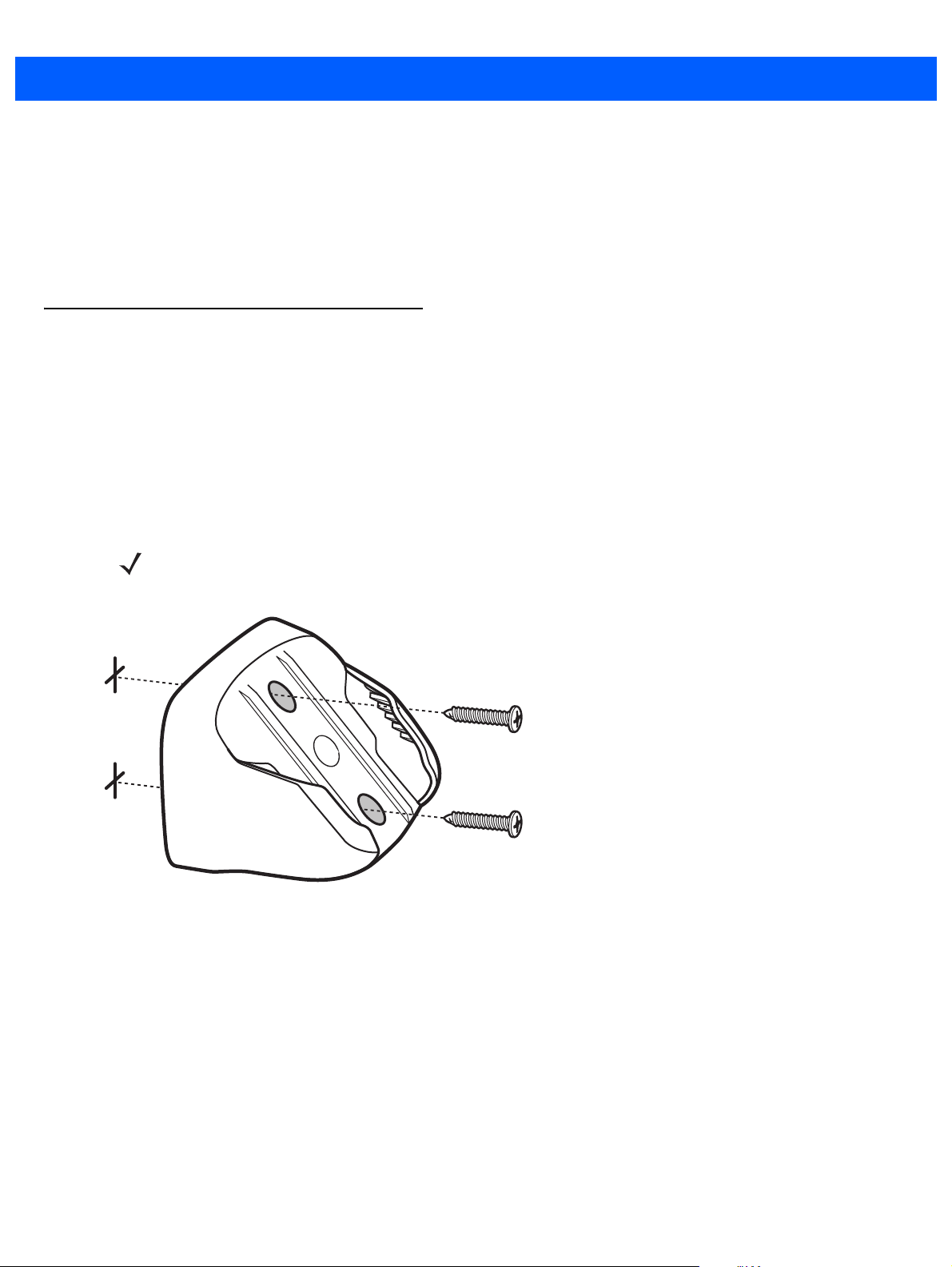
1. Place the bracket in its desired location on the wall, and insert two #8 screws through each screw hole in
the bracket.
NOTE Select a screw type and length appropriate for the wall material.
Figure 1-3
2. Tighten the screws to secure the bracket to the wall.
Installing the Wall Mount Bracket
Page 23
Getting Started 1 - 5
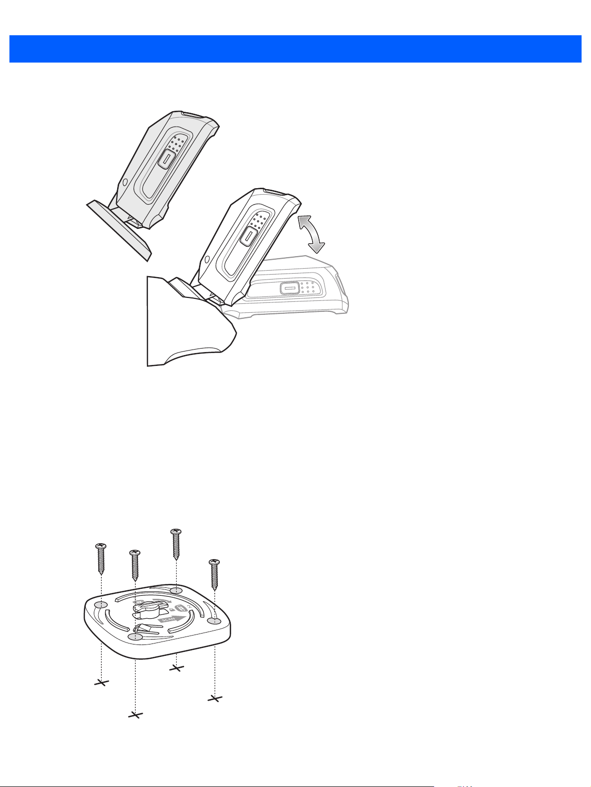
3. Slide the base of the digital scanner into the bracket, oriented so the scan window faces down.
Figure 1-4
Inserting the DS9208-1D into the Wall Mount Bracket
Locking Mount Bracket
An optional locking mount bracket is available for "locking" the scanner into position on a horizontal (or vertical)
surface. This option is recommended for applications where it is desirable to affix the scanner to a counter or
desktop. For a template that facilitates screw placement, see Mounting Templates on page 1-8.
To mount the DS9208-1D:
1. Place the bracket in its desired location on the counter or desktop. Make sure that the indicator on the
bracket is consistent with the direction that the scanner will face. Insert four #8 screws through each screw
hole in the bracket.
Figure 1-5
Figure 1-4 Installing the Locking Mount Bracket
Page 24
1 - 6 DS9208-1D Product Reference Guide
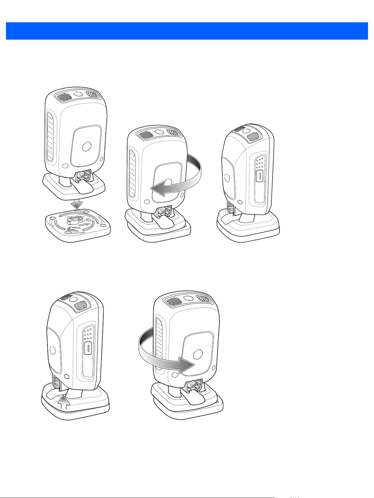
2. Tighten the screws to secure the bracket to the counter or desktop.
3. To insert the scanner into the Locking Mount Bracket, place the scanner onto the bracket and turn it 1/4
revolution clockwise until you hear a click and the scanner faces its final position.
Figure 1-6
4. To remove the scanner from the Locking Mount Bracket, lift the scanner, pull up slightly on the scanner
Inserting the DS9208-1D into the Locking Mount Bracket
with particular emphasis on the right rear corner (where the locking mechanism is) and turn
counter-clockwise until the scanner is released.
Figure 1-7
Removing the DS9208-1D from the Locking Mount Bracket
Page 25

Accessories
Required Accessories
The digital scanner ships with the DS9208 Quick Start Guide. Also order an interface cable for the appropriate
interface, and a universal power supply if the interface requires this. For additional items, contact a local Zebra
representative or business partner.
Optional Accessories
Contact Zebra to purchase the following accessories for the DS9208-1D:
•
Wall Mount Bracket (see Wall Mount Bracket on page 1-4 for installation instructions)
•
Locking Mount Bracket (see Locking Mount Bracket on page 1-5 for installation instructions)
Electronic Article Surveillance (EAS) (Optional)
Getting Started 1 - 7
Because there are several Checkpoint EAS systems available, your local Checkpoint representative should
connect the digital scanner to the Checkpoint EAS system and tune the system. To contact your local
Checkpoint representative inside the U.S. call 800-257-5540, ext. 4300. Outside the U.S., call (609) 848-1800,
ext. 4300.
Page 26
1 - 8 DS9208-1D Product Reference Guide
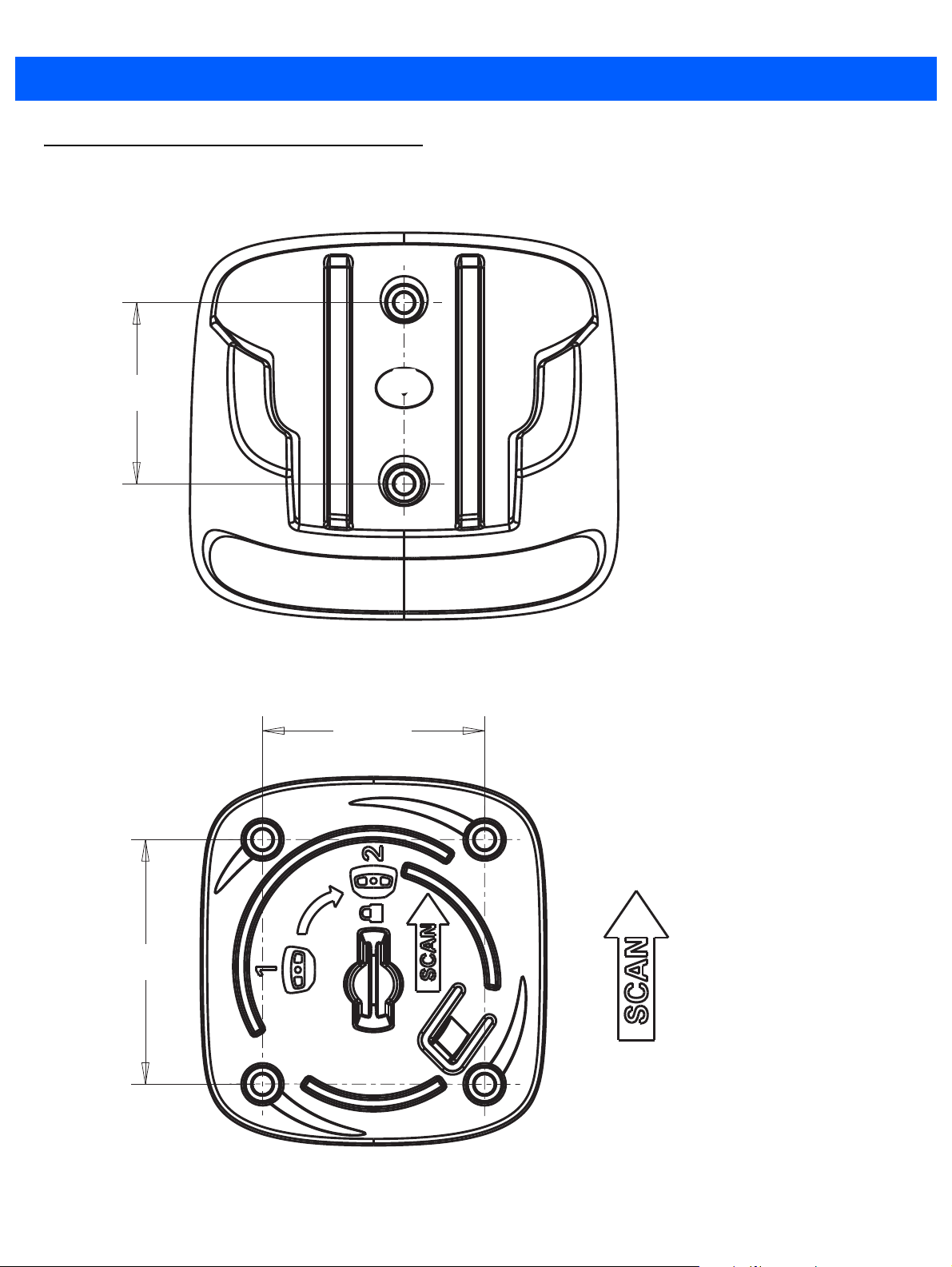
40 mm
54 mm
49 mm
Mounting Templates
Use the following templates to facilitate the proper placement of brackets and screws.
Figure 1-8
Wall Mount Bracket Template
Figure 1-9
Locking Mount Bracket Template
Page 27
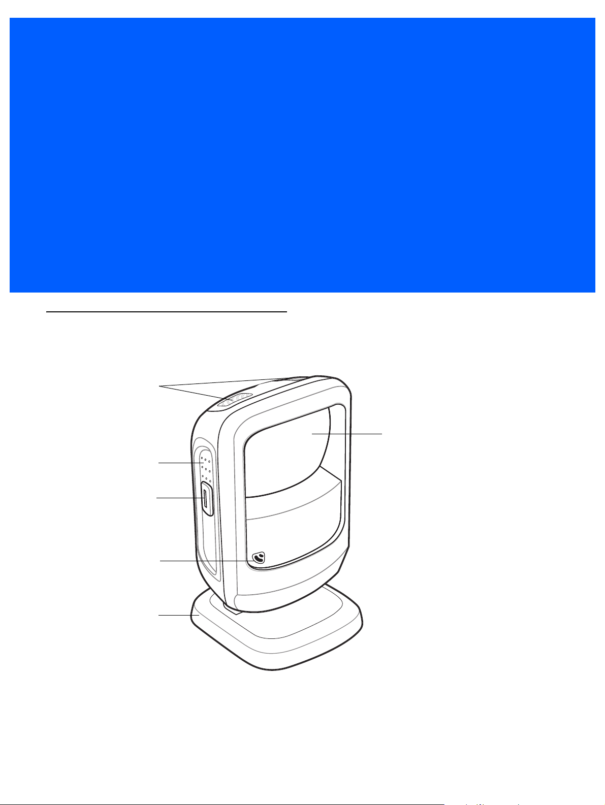
CHAPTER 2 DATA CAPTURE
Decode LEDs
Exit Window
Adjustable Stand
Finger Grips
Trigger and
Volume Control
Beeper
Introduction
This chapter provides beeper and LED definitions, techniques involved in capturing bar codes, general
instructions and tips about scanning, and decode range information.
Figure 2-1
Parts
Page 28

2 - 2 DS9208-1D Product Reference Guide
Beeper Definitions
The digital scanner issues different beep sequences and patterns to indicate status. Table 2-1 defines beep
sequences that occur during both normal scanning and while programming the digital scanner.
Table 2-1
Standard Use
Low/medium/high beeps Power up.
Short beep
(tone programmable)
4 low beeps Transmission error.
5 low beeps Conversion or format error.
Low/low/low/extra low beeps RS-232 receive error.
High beep The digital scanner detected a <BEL> character over RS-232.
Parameter Menu Scanning
High/low beeps Input error; incorrect bar code, programming sequence, or
Low/low beeps Keyboard parameter selected. Enter value using numeric bar codes.
High/low/high/low beeps Successful program exit with change in parameter setting.
ADF Programming
Beeper Definitions
Beeper Sequence Indication
A bar code symbol was decoded (if decode beeper is enabled).
Cancel
scanned.
High/low beeps Enter another digit. Add leading zeros to the front if necessary.
Low/low beeps Enter another alphabetic character or scan the End of Message bar code.
High/high beeps ADF criteria or action is expected. Enter another criterion or action, or scan
the Save Rule bar code.
High/low/high/low beeps Rule saved. Rule entry mode exited.
High/low/low beeps All criteria or actions cleared for current rule, continue entering rule.
Low beep Delete last saved rule. The current rule is left intact.
Low/high/high beeps All rules are deleted.
Low/high/low/high beeps Out of rule memory. Erase some existing rules, then try to save rule again.
Low/high/low beeps Cancel rule entry. Rule entry mode exited because of an error or the user
asked to exit rule entry.
Low/high beeps Entry error, wrong bar code scanned, or criteria/action list is too long for a rule.
Re-enter criterion or action.
Page 29

Data Capture 2 - 3
Table 2-1
Code 39 Buffering
High/low beeps New Code 39 data was entered into the buffer.
3 long high beeps Code 39 buffer is full.
High/low/high beeps The Code 39 buffer was erased.
Low/high/low beeps The Code 39 buffer was erased or there was an attempt to clear or transmit an
Low/high beeps A successful transmission of buffered data.
Host Specific
USB only
Low/medium/high beeps
upon scanning a USB device
type
Low/medium/high beeps
occur more than once
Beeper Definitions (Continued)
Beeper Sequence Indication
empty buffer.
Communication with the host must be established before the digital scanner
can operate at the highest power level.
The USB host can put the digital scanner in a state where power to the
scanner is cycled on and off more than once. This is normal and usually
happens when the PC cold boots.
RS-232 only
1 short high beep A <BEL> character is received and Beep on <BEL> is enabled.
Page 30

2 - 4 DS9208-1D Product Reference Guide
Selecting Beeper Volume using Trigger
The digital scanner emits a short beep when it successfully reads a bar code. To change the volume of the
beep either scan the appropriate bar code in Beeper Volume on page 4-7, or use the trigger as follows:
1. Press and hold the trigger for an extended period of time (5 seconds by default - see Volume Adjustment
Trigger Timeout on page 4-8 to change this). The digital scanner cycles through three settings (High,
Medium, Low) emitting a 2-beep tone at each setting.
2. To select a particular setting, release the trigger after you hear the desired 2-beep tone.
LED Definitions
In addition to beep sequences, the digital scanner uses a two-color LED to indicate status. Table 2-2 defines
LED colors that display during scanning.
Table 2-2
Presentation Mode
Green The scanner is on and ready to scan.
Momentarily Off A bar code was successfully decoded.
Red Transmission error, conversion or format error, or RS-232 receive error.
Off No power is applied to the digital scanner, or the scanner is in low power mode.
Trigger Mode
Green A bar code was successfully decoded.
Red Transmission error, conversion or format error, or RS-232 receive error.
Off No power is applied to the digital scanner, or the scanner is on and ready to scan.
Parameter Programming
Green Number expected. Enter value using numeric bar codes.
Red Input error: incorrect bar code, programming sequence, or Cancel scanned.
Standard LED Definitions
LED Indication
Successful program exit with change in parameter setting.
ADF Programming
Green Enter another digit. Add leading zeros to the front if necessary.
Enter another alphabetic character or scan the
All criteria or actions cleared for current rule, continue entering rule.
Delete last saved rule. The current rule is left intact.
All rules deleted.
Blinking Green Enter another criterion or action, or scan the
Green after Blinking Rule saved. Rule entry mode exited.
Cancel rule entry. Rule entry mode exited because of an error or the user asked to
exit rule entry.
End of Message
Save Rule
bar code.
bar code.
Page 31

Data Capture 2 - 5
Table 2-2
Red Out of rule memory. Erase some existing rules, then try to save rule again.
Firmware update
Red, alternating between
solid and fast blinking
Standard LED Definitions
LED Indication
Scanning
The DS9208 has an integrated, adjustable stand to easily accommodate both
scanning.
Presentation Mode Scanning
For standard operation, the digital scanner is in
are presented in its field of view.
Entry error, wrong bar code scanned, or criteria/action list is too long for a rule.
Re-enter criterion or action.
Firmware download is completing. Wait for this indicator to complete before using
the scanner. This indicator is followed by a low/medium/high power up beep.
presentation mode
presentation
and automatically decodes bar codes that
and triggered
Figure 2-2
Scanning in Presentation Mode, Hands-Free
Page 32

2 - 6 DS9208-1D Product Reference Guide
To scan in hand-held presentation mode, pick up the digital scanner. It remains in presentation mode and
decodes bar codes that are in its field of view.
Figure 2-3
Scanning in Presentation Mode, Hand-Held
Momentary Trigger Mode Scanning
To operate the digital scanner in trigger mode:
1. Pick up the digital scanner. Press and release the trigger. The aiming dot displays.
Figure 2-4
2. Ensure the aiming dot is centered on the bar code. See Aiming in Momentary Trigger Mode.
3. Press and hold the trigger until either:
a. The digital scanner reads the bar code. The digital scanner beeps and the “good decode” LEDs flash.
b. The digital scanner does not read the bar code and illumination turns off.
4. Release the trigger. The aiming dot reappears. To read another bar code, repeat steps 2 and 3.
Scanning in Momentary Trigger Mode
Page 33

Data Capture 2 - 7
012345
012345
012345
012345
After a programmable time period (see Momentary Trigger Mode Timeout on page 4-16), the aiming dot turns
off and the digital scanner returns to presentation mode, ready to read bar codes without use of the trigger. For
beeper definitions, see Table 2-1.
Aiming in Momentary Trigger Mode
When scanning, the digital scanner projects a red aiming dot which allows positioning the bar code within its
field of view. See Decode Ranges on page 2-8 for the proper distance to achieve between the digital scanner
and a symbol.
Figure 2-5
Imager Aiming Dot
If necessary, the digital scanner turns on its red LEDs to illuminate the target symbol.
To scan a symbol, center the aiming dot on the symbol, in any orientation.
Figure 2-6
Scanning Orientation with Imager Aiming Dot
The digital scanner can also decode with the aiming dot on a symbol but not centered. The top examples in
Figure 2-7 show acceptable aiming options, while the bottom examples may not be decoded.
Figure 2-7
Acceptable and Incorrect Aiming
The aiming dot is smaller when the digital scanner is closer to the symbol and larger when it is farther from the
symbol. Scan symbols with smaller bars or elements (mil size) closer to the digital scanner, and those with
larger bars or elements (mil size) farther from the digital scanner.
The digital scanner beeps to indicate that it successfully decoded the symbol. For more information on beeper
and LED definitions, see Table 2-1 and Table 2-2.
Page 34

2 - 8 DS9208-1D Product Reference Guide
Decode Ranges
Table 2-3
Symbol Density Bar Code Type
Decode Ranges
Typical Working Ranges
Near Far
5.0 mil Code 39 0 in / 0 cm 4.5 in / 11.4 cm
10 mil 80% UPCEAN 0 in / 0 cm 8.5 in / 21.6 cm
13 mil 100% UPC 0 in / 0 cm 10.5 in / 26.7 cm
Integrated Electronic Article Surveillance (EAS)
Deactivation Antenna for Checkpoint EAS Systems
The digital scanner’s optional EAS deactivation feature includes an integrated RF antenna which, when
attached to a Checkpoint EAS deactivation system, supports deactivation of EAS security labels while
scanning a product at the Point-of-Sale. This allows removing the merchandise from the store without
activating the security alarm.
NOTE Contact your local Checkpoint representative to help connect the EAS deactivation system to insure
proper operation.
EAS Deactivation Range
There are several adjustments that can be made on the Checkpoint Deactivation System side. Contact
Checkpoint Systems, Inc. for details.
DS9208 Host Interface Cables and EAS
The digital scanner requires a special EAS scanner cable to connect to the Checkpoint EAS deactivation
system. These cables are available for a variety of hosts types (e.g., USB, RS-232, RS-485).
Checkpoint Contact Information
Checkpoint Headquarters (New Jersey): 800-257-5540.
Outside the United States: +1-856-848-1800.
Page 35

CHAPTER 3 MAINTENANCE & TECHNICAL
SPECIFICATIONS
Introduction
This chapter provides suggested digital scanner maintenance, troubleshooting, technical specifications, and
signal descriptions (pinouts).
Maintenance
Cleaning the scan window is the only maintenance required. A dirty window can affect scanning accuracy.
•
Do not allow abrasive material to touch the window.
•
Remove any dirt particles with a damp cloth.
•
Wipe the window using a dust-free soft cloth moistened with isopropyl alcohol-based cleaner. Do not let
liquid pool around the window or any other area on the scanner.
•
Do not spray water or other cleaning liquids directly into the window.
Page 36

3 - 2 DS9208-1D Product Reference Guide
Troubleshooting
Table 3-1
The aiming dot does not
appear when pressing the
trigger.
Digital scanner emits short
low/short medium/short high
beep sequence (power-up
beep sequence) more than
once.
Troubleshooting
Problem Possible Causes Possible Solutions
No power to the digital scanner. If the configuration requires a power
supply, re-connect the power supply.
Incorrect host interface cable is
used.
Interface/power cables are loose. Re-connect cables.
Digital scanner is disabled. For IBM 468x and USB IBM hand-held,
If using RS-232 Nixdorf B mode,
CTS is not asserted.
Aiming dot is disabled. Enable the aiming dot. See
The USB bus may put the digital
scanner in a state where power to
the scanner is cycled on and off
more than once.
Connect the correct host interface
cable.
IBM table top, and OPOS modes,
enable the digital scanner via the host
interface. Otherwise, see the technical
person in charge of scanning.
Assert CTS line.
Trigger
Aiming Pattern on page 4-14
Normal during host reset.
.
Digital scanner emits aiming
dot, but does not decode the
bar code.
Digital scanner is not programmed
for that bar code type.
Bar code symbol is unreadable. Scan test symbols of the same bar
The aiming dot is not centered on
the symbol.
Picklist mode is preventing the
digital scanner from decoding all bar
codes in the field of view.
Program the digital scanner to read that
type of bar code. See
Symbologies
code type to determine if the bar code
is defaced.
Center the aiming dot on the symbol.
See
Aiming in Momentary Trigger
Mode on page 2-7
Disable Picklist mode. See
Mode on page 4-23
.
Chapter 9,
.
Picklist
.
Page 37

Maintenance & Technical Specifications 3 - 3
Table 3-1
Digital scanner decodes bar
code, but does not transmit
the data to the host.
Host displays scanned data
incorrectly.
Troubleshooting (Continued)
Problem Possible Causes Possible Solutions
Digital scanner is not programmed
for the correct host type.
Interface cable is loose. Re-connect the cable.
If the digital scanner emits 4 long
low beeps, a transmission error
occurred.
If the digital scanner emits 5 low
beeps, a conversion or format error
occurred.
If the digital scanner emits
low/high/low beeps, it detected an
invalid ADF rule.
If the digital scanner emits high/low
beeps, the scanner is buffering
Code 39 data.
Digital scanner is not programmed
to work with the host.
Scan the appropriate host type
programming bar code. See the
chapter corresponding to the host type.
Set the scanner's communication
parameters to match the host's setting.
Configure the digital scanner's
conversion parameters properly.
Program the correct ADF rules. Refer
to the Advanced Data Formatting
Programmer Guide.
Normal scanning a Code 39 bar code
and the Code 39 Buffering option is
enabled.
Scan the appropriate host type
programming bar code.
Digital scanner emits
low/low/low/extra low beeps
when not in use.
Digital scanner emits low/high
beeps during programming.
Digital scanner emits
low/high/low/high beeps
during programming.
For RS-232, set the digital scanner's
communication parameters to match
the host's settings.
For a Keyboard Wedge configuration,
program the system for the correct
keyboard type, and turn off the CAPS
LOCK key.
Program the proper editing options
(e.g., UPC-E to UPC-A Conversion).
RS-232 receive error. Normal during host reset. Otherwise,
set the digital scanner's RS-232 parity
to match the host setting.
Input error or
scanned.
Out of ADF parameter storage
space.
Cancel
bar code was
Scan the correct numeric bar codes
within range for the parameter
programmed.
Erase all rules and re-program with
shorter rules.
Page 38

3 - 4 DS9208-1D Product Reference Guide
Table 3-1
Digital scanner emits
low/high/low beeps.
Digital scanner emits a
power-up beep after changing
USB host type.
Digital scanner emits one high
beep when not in use.
Troubleshooting (Continued)
Problem Possible Causes Possible Solutions
Clearing Code 39 buffer. Normal when scanning the Code 39
Buffering
upon attempt to transmit an empty
Code 39 buffer.
The USB bus re-established power
to the digital scanner.
In RS-232 mode, a <BEL> character
was received and Beep on <BEL>
option is enabled.
NOTE If after performing these checks the digital scanner still experiences problems, contact the distributor or
Zebra support. See page xvi for contact information.
Normal when changing USB host type.
Normal when
enabled and the digital scanner is in
RS-232 mode.
Clear Buffer
Beep on <BEL>
Report Software Version Bar Code
When contacting Zebra support, a support representative may ask you to scan the bar code below to
determine the version of software installed in the digital scanner.
bar code or
is
Report Software Version
Page 39

Technical Specifications
Maintenance & Technical Specifications 3 - 5
Table 3-2
Physical Characteristics
Dimensions 5.512 in H x 3.232 in W x 3.150 in D
Weight 9.5 oz (269.3 g)
Voltage and Current Idle: 5 +/-10% VDC @ 150 ma average
Performance Characteristics
Light Source Aiming dot: 625 nm LED
Imager Field of View
(Horizontal x Vertical)
Roll
Pitch
Yaw
Swipe Speed Up to 90 in (2.3 m) per second
Technical Specifications
Item Description
14.0 cm H x 8.21 cm W x 8.0 cm D
Scanning: 5 +/-10% VDC @ 230 ma average
Illumination: 630 nm LEDs
46º H x 29.5º V
360º
+/- 65º
+/- 60º
Symbology Decode Capability
1D UPC/EAN (UPC-A/UPC-E/UPC-E1/EAN-8/EAN-13/JAN-8/JAN-13 plus
supplementals, ISBN (Bookland), ISSN, Coupon Code), Code 39 (Standard,
Full ASCII, Trioptic, Code 32 (Italian Pharmacode)), Code 128 (Standard, Full
ASCII, UCC/EAN-128, ISBT-128 Concatenated), Code 93, Codabar/NW7,
2 of 5 (Interleaved 2 of 5, Discrete 2 of 5, IATA, Chinese 2 of 5, Matrix 2 of 5,
Code 11), MSI Plessey, GS1 DataBar (Omnidirectional, Truncated, Stacked,
Stacked Omnidirectional, Limited, Expanded, Expanded Stacked)
Minimum Resolution Code 39 – 4 mil,
UPC – 7.8 mil (60%)
Typical Working Distance See
Interfaces Supported
User Environment
Operating Temperature 32º F to 104º F (0º C to 40º C)
Humidity 5% to 85% RH, non-condensing
Drop Specifications Withstands multiple 5 ft. (1.5 m) drops to concrete
Sealing IP50
Decode Ranges on page 2-8
USB, RS-232, RS-485 (IBM 46xx protocols), keyboard wedge
.
Page 40

3 - 6 DS9208-1D Product Reference Guide
Table 3-2
Ambient Light Immunity Immune to natural and artificial ambient light (i.e., sunlight, incandescent,
Options
Electronic Article Surveillance
(EAS)
Mounting Options Wall mount bracket, locking mount bracket
Technical Specifications (Continued)
Item Description
fluorescent, mercury vapor, sodium vapor)
Compatible with Checkpoint EAS deactivation systems
Page 41

Digital Scanner Signal Descriptions
Pin 1
Pin 10
Interface cable
modular connector
Maintenance & Technical Specifications 3 - 7
Figure 3-1
The signal descriptions in Table 3-3 apply to the connectors on the DS9208 digital scanner and are for
reference only.
Table 3-3
Pin IBM RS-232
1
2
3
4
5
6
7
8
9
10
Digital Scanner Cable Pinouts
DS9208 Digital Scanner Signal Pin-outs
Keyboard
Wedge
Reserved Reserved Reserved Jump to Pin 6
Power Power Power Power
Ground Ground Ground Ground
IBM_A(+) TxD KeyClock Reserved
Reserved RxD TermData D +
IBM_B(-) RTS KeyData Jump to Pin 1
Reserved CTS TermClock D -
Reserved Reserved Reserved Reserved
Reserved Reserved Reserved Reserved
Reserved Reserved Reserved Reserved
USB
Page 42

3 - 8 DS9208-1D Product Reference Guide
Page 43

CHAPTER 4 USER PREFERENCES &
*High Volume
(00h)
Feature/Option
* Indicates Default
Option Hex Value
MISCELLANEOUS OPTIONS
Introduction
You can program the digital scanner to perform various functions, or activate different features. This chapter
describes each user preference feature and provides programming bar codes for selecting these features.
The digital scanner ships with the settings shown in Table 4-1 on page 4-2 (also see Appendix A, Standard
Default Parameters for all host device and miscellaneous defaults). If the default values suit requirements,
programming is not necessary.
To set feature values, scan a single bar code or a short bar code sequence. The settings are stored in
non-volatile memory and are preserved even when the digital scanner is powered down.
NOTE Most computer monitors allow scanning the bar codes directly on the screen (when using the imaging
engine). When scanning from the screen, be sure to set the document magnification to a level where you
can see the bar code clearly, and bars and/or spaces are not merging.
If not using a USB cable, select a host type (see each host chapter for specific host information) after the
power-up beeps sound. This is only necessary upon the first power-up when connected to a new host.
To return all features to default values, scan the Set Default Parameter on page 4-4. Throughout the
programming bar code menus, asterisks indicate (
*) default values.
Page 44

4 - 2 DS9208-1D Product Reference Guide
Scanning Sequence Examples
In most cases, scanning one bar code sets the parameter value. For example, to set the beeper tone to high,
scan the High Frequency (beeper tone) bar code listed under Beeper Tone on page 4-6. The digital scanner
issues a fast warble beep and the LED turns green, signifying a successful parameter entry.
Other parameters, such as Serial Response Timeout or Data Transmission Formats, require scanning
several bar codes. See these parameter descriptions for this procedure.
Errors While Scanning
Unless otherwise specified, to correct an error during a scanning sequence, just re-scan the correct parameter.
User Preferences/Miscellaneous Options Parameter Defaults
Table 4-1 lists defaults for user preferences parameters. To change the default values, scan the appropriate
bar codes in this guide. These new values replace the standard default values in memory. To recall the default
parameter values, scan the Set Default Parameter on page 4-4.
NOTE See Appendix A, Standard Default Parameters for all user preferences, hosts, symbologies, and
miscellaneous default parameters.
Table 4-1
User Preferences
Set Default Parameter Set Defaults
Parameter Bar Code Scanning ECh Enable
Beep After Good Decode 38h Enable
Beeper Tone 91h Medium
Beeper Volume 8Ch High
Volume Adjustment Trigger Timeout F0h 93h 5.0 Sec
Beeper Duration F1h 74h Medium
Suppress Power-up Beeps F1h D1h Do not suppress
Low Power Mode 80h Disable
Time Delay to Low Power Mode 92h 1 Hour
User Preferences Parameter Defaults
Parameter
Parameter
Number
Default
Page
Number
4-4
4-5
4-5
4-6
4-7
4-8
4-9
4-9
4-10
4-11
Trigger Mode 8Ah Presentation
Trigger Aiming Pattern F0h 32h Enable
Presentation Aiming Pattern F1h 4Eh Disable
Momentary Trigger Mode Timeout EDh 5 sec
Motion Detect Range F2h 3Bh Full
4-13
4-14
4-15
4-16
4-17
Page 45

User Preferences & Miscellaneous Options 4 - 3
Table 4-1
Decoding Illumination (Hand-Held Mode Only) F0h, 2Ah Enable
Post Decode Illumination F2h 29h Always Off
Illumination Always On
(Presentation Mode Only)
Illumination Control Timer (Dim Mode) F1h 97h 1 minute
Presentation Mode Field of View F1h 61h Small
Picklist Mode F0h 92h Enabled in Trigger Mode
Continuous Bar Code Read F1h 89h Disable
Unique Bar Code Reporting F1h D31h Disable
Decode Session Timeout 88h 9.9 Sec
Timeout Between Decodes, Same Symbol 89h 0.4 Sec
Timeout Between Decodes, Different Symbols 90h 0.2 Sec
Fuzzy 1D Processing F1h 02h Enable
User Preferences Parameter Defaults (Continued)
Parameter
Parameter
Number
F2h 59h Illumination Automatically
Default
Controlled
Page
Number
4-18
4-18
4-19
4-20
4-22
4-23
4-24
4-24
4-25
4-25
4-26
4-26
Motion Tolerance
(Hand-Held Trigger Modes Only)
Miscellaneous Options
Transmit Code ID Character 2Dh None
Prefix Value 63h, 69h 7013 <CR><LF>
Suffix 1 Value
Suffix 2 Value
Scan Data Transmission Format EBh Data as is
FN1 Substitution Values 67h 6Dh Set
Transmit “No Read” Message 5Eh Disable
F2h 5Ah Less Motion Tolerance
62h 68h
64h 6Ah
7013 <CR><LF>
4-27
4-28
4-29
4-29
4-30
4-31
4-32
Page 46

4 - 4 DS9208-1D Product Reference Guide
User Preferences
Set Default Parameter
You can reset the digital scanner to two types of defaults: factory defaults or custom defaults. Scan the
appropriate bar code below to reset the digital scanner to its default settings and/or set its current settings as
custom defaults.
•
Set Defaults - Scan this bar code to reset all default parameters as follows.
• If you previously set custom defaults by scanning Write to Custom Defaults, scan Set Defaults to
retrieve and restore the digital scanner’s custom default settings.
• If you did not set custom defaults, scan Set Defaults to restore the factory default values listed in
Table A-1.
•
Set Factory Defaults - Scan this bar code to restore the factory default values listed in Table A-1. This
deletes any custom defaults set.
•
Write to Custom Defaults - Scan this bar code to set the current digital scanner settings as custom
defaults. Once set, you can recover custom default settings by scanning Set Defaults.
*Set Defaults
Write to Custom Defaults
Set Factory Defaults
Page 47

User Preferences & Miscellaneous Options 4 - 5
Parameter Bar Code Scanning
Parameter # ECh
To disable the decoding of parameter bar codes, including the Set Defaults parameter bar codes, scan the
Disable Parameter Scanning bar code below. To enable decoding of parameter bar codes, scan Enable
Parameter Scanning.
*Enable Parameter Bar Code Scanning
(01h)
Disable Parameter Bar Code Scanning
(00h)
Beep After Good Decode
Parameter # 38h
Scan a bar code below to select whether or not the digital scanner beeps after a good decode. If selecting Do
Not Beep After Good Decode, the beeper still operates during parameter menu scanning and to indicate
error conditions.
*Beep After Good Decode
(Enable)
(01h)
Do Not Beep After Good Decode
(Disable)
(00h)
Page 48

4 - 6 DS9208-1D Product Reference Guide
Beeper Tone
Parameter # 91h
To select a decode beep frequency (tone), scan one of the following bar codes.
Off
(03h)
Low Tone
(02h)
*Medium Tone
(01h)
Medium to High Tone (2-tone)
(04h)
High Tone
(00h)
Page 49

User Preferences & Miscellaneous Options 4 - 7
Beeper Volume
Parameter # 8Ch
To select a beeper volume, scan the Low Vol u m e , Medium Volume, or High Volume bar code.
Low Volume
(02h)
Medium Volume
(01h)
*High Volume
(00h)
Page 50

4 - 8 DS9208-1D Product Reference Guide
Volume Adjustment Trigger Timeout
Parameter # F0h 93h
Use this parameter to set the length of time needed to hold the trigger to adjust the volume. The scanner
changes volume and beeps with the new volume.
Volume Adjustment Trigger Timeout 3 sec
(1Eh)
*Volume Adjustment Trigger Timeout 5 sec
(32h)
Volume Adjustment Trigger Timeout 7 sec
(46h)
Page 51

User Preferences & Miscellaneous Options 4 - 9
Beeper Duration
Parameter # F1h 74h
To select the duration for the beeper, scan one of the following bar codes.
Short
(00h)
* Medium
(01h)
Long
(02h)
Suppress Power-up Beeps
Parameter # F1h D1h
Select whether or not to suppress the digital scanner’s power-up beeps.
Suppress Power-up Beeps
(01h)
* Do Not Suppress Power-up Beeps
(00h)
Page 52

4 - 10 DS9208-1D Product Reference Guide
Low Power Mode
Parameter # 80h
This parameter determines whether or not the digital scanner enters low power mode after a decode attempt.
If disabled, power remains on after each decode attempt.
*Disable Low Power Mode
(00h)
Enable Low Power Mode
(01h)
Page 53

User Preferences & Miscellaneous Options 4 - 11
Time Delay to Low Power Mode
Parameter # 92h
NOTE This parameter only applies when Low Power Mode is enabled.
This parameter sets the time the digital scanner remains active before entering low power mode. The digital
scanner wakes upon trigger pull or when the host attempts to communicate with the digital scanner.
1 Second
(11h)
1 Minute
(21h)
15 Minutes
(2Bh)
10 Seconds
(1Ah)
5 Minutes
(25h)
Page 54

4 - 12 DS9208-1D Product Reference Guide
Time Delay to Low Power Mode (continued)
30 Minutes
(2Dh)
45 Minutes
(2Eh)
*1 Hour
(31h)
6 Hours
(36h)
3 Hours
(33h)
9 Hours
(39h)
Page 55

Trigger Mode
Parameter # 8Ah
Select one of the following trigger modes for the digital scanner:
•
Standard (Level) - A trigger pull activates decode processing. Decode processing continues until the bar
code decodes, you release the trigger, or the Decode Session Timeout occurs.
•
Presentation - The digital scanner activates decode processing when it detects a bar code in its field of
view. After a period of non-use, the digital scanner enters a low power mode, in which the LEDs turn off
until the digital scanner senses motion.
•
Auto Aim - This trigger mode turns on the LED aiming dot when you lift the digital scanner. A trigger pull
activates decode processing. After 2 seconds of inactivity the aiming dot shuts off.
Standard (Level)
(00h)
User Preferences & Miscellaneous Options 4 - 13
Auto Aim
(09h)
*Presentation
(07h)
Page 56

4 - 14 DS9208-1D Product Reference Guide
Trigger Aiming Pattern
Parameter # F0h, 32h
Select Enable Trigger Aiming Pattern to project the aiming pattern during bar code capture in trigger mode,
or Disable Trigger Aiming Pattern to turn the aiming pattern off.
NOTE With Picklist Mode on page 4-23 enabled, the decode aiming pattern flashes even when the Decode
Aiming Pattern is disabled.
*Enable Trigger Aiming Pattern
(02h)
Disable Trigger Aiming Pattern
(00h)
Page 57

User Preferences & Miscellaneous Options 4 - 15
Presentation Aiming Pattern
Parameter # F1h, 4Eh
Select Enable Presentation Aiming Pattern to project the aiming pattern during bar code capture in
presentation mode or Disable Presentation Aiming Pattern to turn the aiming pattern off.
NOTE With Picklist Mode on page 4-23 enabled, the decode aiming pattern flashes even when the Decode
Aiming Pattern is disabled.
Enable Presentation Aiming Pattern
(01h)
*Disable Presentation Aiming Pattern
(00h)
Page 58

4 - 16 DS9208-1D Product Reference Guide
Momentary Trigger Mode Timeout
Parameter # EDh
In momentary trigger mode, the aiming dot appears upon pressing the trigger. Once in this mode, upon each
trigger press the scanner attempts to decode the bar code in front of it. After a period of inactivity while the
trigger is not pressed, the scanner reverts to presentation mode where there is no illumination until an item is
presented.
This parameter controls the length of the period of inactivity in momentary trigger mode before the scanner
reverts to presentation mode.
Momentary Trigger Mode Timeout - 2 Seconds
(14h)
Momentary Trigger Mode Timeout - 4 Seconds
(28h)
Momentary Trigger Mode Timeout - 3 Seconds
(1Eh)
*Momentary Trigger Mode Timeout - 5 Seconds
(32h)
Page 59

User Preferences & Miscellaneous Options 4 - 17
Motion Detect Range
Parameter # F2h 3Bh
This parameter controls the distance, or range, at which the scanner detects object motion and then triggers
while in Presentation Mode.
*Full Range
(01h)
Medium Range
(03h)
Short Range
(08h)
Page 60

4 - 18 DS9208-1D Product Reference Guide
Decoding Illumination (Hand-Held Mode Only)
Parameter # F0h, 2Ah
When in hand-held mode, selecting Enable Decoding Illumination causes the digital scanner to flash
illumination to aid decoding. Select Disable Decoding Illumination to prevent the digital scanner from using
decoding illumination.
Enabling illumination usually results in superior images. The effectiveness of the illumination decreases as the
distance to the target increases.
*Enable Decoding Illumination
(01h)
Disable Decoding Illumination
(00h)
Post Decode Illumination
Parameter # F2h 29h
This parameter controls illumination after decode. Select Always Off to turn off illumination immediately after
decode. Select
keep illumination on until timeout.
Always On to keep Illumination on after decode so the scanner is ready for next decode, or to
Always On
(00h)
*Always Off
(01h)
Page 61

User Preferences & Miscellaneous Options 4 - 19
Illumination Always On (Presentation Mode Only)
Parameter # F2h 59h
Select Illumination Always On to keep the illumination LEDs on all the time. In this mode, the scanner
bypasses IR detection and aggressively decodes the bar code presented in its field of view.
NOTE If you select Illumination Always On and the Post Decode Illumination is disabled, Illumination
Always On takes precedence.
*Illumination Automatically Controlled
(00h)
Illumination Always On
(01h)
Page 62

4 - 20 DS9208-1D Product Reference Guide
Illumination Control Timer (Dim Mode)
Parameter # F1h 97h
When Illumination Always On (Presentation Mode Only) is enabled, this parameter sets the time the scanner
remains active before lowering illumination to dim mode until the next bar code is presented.
Disable
(00h)
1 Second
(01h)
10 Seconds
(0Ah)
5 Minutes
(15h)
*1 Minute
(11h)
15 Minutes
(1Bh)
Page 63

Illumination Control (continued)
30 Minutes
(1Dh)
User Preferences & Miscellaneous Options 4 - 21
45 Minutes
(1Eh)
1 Hour
(21h)
6 Hours
(26h)
3 Hours
(23h)
9 Hours
(29h)
Page 64

4 - 22 DS9208-1D Product Reference Guide
Presentation Mode Field of View
Parameter # F1h 61h
In presentation mode, by default the digital scanner searches the larger area of the aiming pattern (Full Field of
View
).
To search for a bar code in a smaller region around the aiming pattern’s center cross in order to speed search
time, select
Small Field of View or Medium Field of View.
*Small Field of View
(00h)
Full Field of View
(02h)
Medium Field of View
(01h)
Page 65

User Preferences & Miscellaneous Options 4 - 23
Picklist Mode
Parameter # F0h 92h
Picklist mode enables the digital scanner to decode only the bar code targeted by the aiming dot. Select one of
the following picklist modes for the digital scanner:
•
Disabled - Picklist mode is always disabled.
•
Enabled in Trigger Mode - Picklist mode is enabled when the digital scanner is out of trigger mode and
disabled when the digital scanner is in presentation mode.
•
Enabled Always - Picklist mode is always enabled.
NOTE Picklist mode functions optimally when bar codes are vertically spaced a minimum of 15 mm edge to edge.
Disabled
(00h)
Enabled Always
(02h)
*Enabled in Trigger Mode
(01h)
Page 66

4 - 24 DS9208-1D Product Reference Guide
Continuous Bar Code Read
Parameter # F1h 89h
Enable this to report every bar code while the trigger is pressed.
NOTE Zebra strongly recommends enabling Picklist Mode with this feature. Disabling Picklist Mode can cause
accidental decodes when more than one bar code is in the imaging engine's field of view.
*Disable Continuous Bar Code Read
(00h)
Enable Continuous Bar Code Read
(01h)
Unique Bar Code Reporting
Parameter # F1h D3h
Enable this to report only unique bar codes while the trigger is pressed. This option only applies when
Continuous Bar Code Read is enabled.
*Disable Continuous Bar Code Read Uniqueness
(00h)
Enable Continuous Bar Code Read Uniqueness
(01h)
Page 67

User Preferences & Miscellaneous Options 4 - 25
Decode Session Timeout
Parameter # 88h
This parameter sets the maximum time decode processing continues during a scan attempt. It is
programmable in 0.1 second increments from 0.5 to 9.9 seconds. The default timeout is 9.9 seconds.
To set a Decode Session Timeout, scan the bar code below. Next, scan two numeric bar codes from Appendix
D, Numeric Bar Codes that correspond to the desired on time. Enter a leading zero for single digit numbers.
For example, to set a Decode Session Timeout of 0.5 seconds, scan the bar code below, then scan the 0 and
5 bar codes. To correct an error or change the selection, scan Cancel on page D-2.
NOTE The Decode Session Timeout cannot be less than or equal to either Timeout Between Decodes, Same
Symbol or Timeout Between Decodes, Different Symbols.
Decode Session Timeout
Timeout Between Decodes, Same Symbol
Parameter # 89h
Use this option in presentation mode and Continuous Bar Code Read to prevent the beeper from continuously
beeping when a symbol is left in the digital scanner’s field of view. It is programmable in 0.1 second increments
from 0.0 to 9.9 seconds. The default interval is 0.4 seconds.
To select the timeout between decodes for the same symbol, scan the bar code below, then scan two numeric
bar codes from Appendix D, Numeric Bar Codes that correspond to the desired interval, in 0.1 second
increments.
NOTE The Timeout between Decodes, Same Symbol cannot be greater than or equal to the Decode Session
Timeout.
Timeout Between Decodes, Same Symbol
Page 68

4 - 26 DS9208-1D Product Reference Guide
Timeout Between Decodes, Different Symbols
Parameter # 90h
Use this option in presentation mode and Continuous Bar Code Read to control the time the scanner is inactive
between decoding different symbols. It is programmable in 0.1 second increments from 0.1 to 9.9 seconds.
The default is 0.2 seconds.
To select the timeout between decodes for different symbols, scan the bar code below, then scan two numeric
bar codes from Appendix D, Numeric Bar Codes that correspond to the desired interval, in 0.1 second
increments.
NOTE The Timeout between Decodes, Different Symbols cannot be greater than or equal to the Decode
Session Timeout.
Timeout Between Decodes, Different Symbols
Fuzzy 1D Processing
Parameter # F1h 02h
This option is enabled by default to optimize decode performance on 1D bar codes, including damaged and
poor quality symbols. Disable this only if you experience time delays when detecting a no decode.
*Enable Fuzzy 1D Processing
(01h)
Disable Fuzzy 1D Processing
(00h)
Page 69

User Preferences & Miscellaneous Options 4 - 27
Motion Tolerance (Hand-Held Trigger Modes Only)
Parameter # F2h 5Ah
Less Motion Tolerance provides optimal decoding performance on 1D bar codes.
To increase motion tolerance and speed decoding when scanning a series of 1D bar codes in rapid
progression, scan More Motion Tolerance.
*Less Motion Tolerance
(00h)
More Motion Tolerance
(01h)
Page 70

4 - 28 DS9208-1D Product Reference Guide
Miscellaneous Scanner Parameters
Transmit Code ID Character
Parameter # 2Dh
A Code ID character identifies the code type of a scanned bar code. This is useful when decoding more than
one code type. In addition to any single character prefix already selected, the Code ID character is inserted
between the prefix and the decoded symbol.
Select no Code ID character, a Symbol Code ID character, or an AIM Code ID character. For Code ID
Characters, see Symbol Code Identifiers on page B-1 and AIM Code Identifiers on page B-2.
NOTE If you enable Symbol Code ID Character or AIM Code ID Character, and enable Transmit “No Read”
Message on page 4-32, the digital scanner appends the code ID for Code 39 to the NR message.
Symbol Code ID Character
(02h)
*None
(00h)
AIM Code ID Character
(01h)
Page 71

User Preferences & Miscellaneous Options 4 - 29
Prefix/Suffix Values
Key Category Parameter # P = 63h, S1 = 62h, S2 = 64h
Decimal Value Parameter # P = 69h, S1 = 68h, S2 = 6Ah
You can append a prefix and/or one or two suffixes to scan data for use in data editing. To set a value for a
prefix or suffix, scan a four-digit number (i.e., four bar codes from Appendix D, Numeric Bar Codes) that
corresponds to that value. See Table E-1 on page E-1 for the four-digit codes.
When using host commands to set the prefix or suffix, set the key category parameter to 1, then set the 3-digit
decimal value. See Table E-1 on page E-1 for the four-digit codes.
To correct an error or change a selection, scan Cancel on page D-2.
NOTE To use Prefix/Suffix values, first set the Scan Data Transmission Format on page 4-30.
Scan Prefix
(07h)
Scan Suffix 2
(08h)
Scan Suffix 1
(06h)
Data Format Cancel
Page 72

4 - 30 DS9208-1D Product Reference Guide
Scan Data Transmission Format
Parameter # EBh
To set the scan data format, scan one of the following bar codes.
NOTE If using this parameter do not use ADF rules to set the prefix/suffix.
To set values for the prefix and/or suffix, see Prefix/Suffix Values on page 4-29.
*Data As Is
(00h)
<DATA> <SUFFIX 2>
(02h)
<PREFIX> <DATA >
(04h)
<DATA> <SUFFIX 1>
(01h)
<DATA> <SUFFIX 1> <SUFFIX 2>
(03h)
Page 73

Scan Data Transmission Format (continued)
<PREFIX> <DATA> <SUFFIX 1>
(05h)
User Preferences & Miscellaneous Options 4 - 31
<PREFIX> <DATA> <SUFFIX 2>
(06h)
<PREFIX> <DATA> <SUFFIX 1> <SUFFIX 2>
(07h)
FN1 Substitution Values
Key Category Parameter # 67h
Decimal Value Parameter # 6Dh
The wedge and USB HID keyboard hosts support a FN1 Substitution feature. Enabling this substitutes any
FN1 character (0x1b) in an EAN128 bar code with a value. This value defaults to 7013 (Enter key).
When using host commands to set the FN1 substitution value, set the key category parameter to 1, then set
the 3-digit keystroke value. See the ASCII character set table for the current host interface for the desired
value.
To select a FN1 substitution value via bar code menus:
1. Scan the bar code below.
Set FN1 Substitution Value
2. Locate the keystroke desired for FN1 substitution in the ASCII character set table in the appropriate host
interface chapter. Enter the 4-digit ASCII value by scanning each digit in Appendix D, Numeric Bar Codes.
To correct an error or change the selection, scan Cancel on page D-2.
See USB Keyboard FN 1 Substitution on page 5-13 to enable FN1 substitution for the USB HID keyboard.
Page 74

4 - 32 DS9208-1D Product Reference Guide
Transmit “No Read” Message
Parameter # 5Eh
Scan a bar code below to select whether or not to transmit a No Read message. Enable this to transmit the
characters NR when a successful decode does not occur before trigger release or the
expires. See Decode Session Timeout on page 4-25. Disable this to send nothing to the host if a symbol does
not decode.
NOTE If you enable Transmit No Read, and also enable Symbol Code ID Character or AIM Code ID Character
for Transmit Code ID Character on page 4-28, the digital scanner appends the code ID for Code 39 to the
NR message.
Enable No Read
(01h)
Decode Session Timeout
*Disable No Read
(00h)
Page 75

CHAPTER 5 USB INTERFACE
*North American Standard USB Keyboard
Feature/Option
*Indicates Default
Introduction
This chapter describes how to set up the digital scanner with a USB host. The digital scanner connects directly
to a USB host, or a powered USB hub, which powers it. No additional power supply is required.
Throughout the programming bar code menus, asterisks (
NOTE Most computer monitors allow scanning the bar codes directly on the screen. When scanning from the
screen, be sure to set the document magnification to a level where you can see the bar code clearly, and
bars and/or spaces are not merging.
*) indicate default values.
Page 76

5 - 2 DS9208-1D Product Reference Guide
USB Connector
Interface Cable
Connecting a USB Interface
Figure 5-1
The digital scanner connects with USB-capable hosts including:
•
•
The following operating systems support the digital scanner through USB:
•
•
•
The digital scanner also interfaces with other USB hosts which support USB Human Interface Devices (HID).
To set up the digital scanner:
1. Connect the modular connector of the USB interface cable to the cable interface port on the digital scanner
(see Installing the Interface Cable on page 1-3).
USB Connection
Desktop PCs and notebooks
• Apple™ iMac, G4, iBooks (North America only)
• IBM SurePOS terminals
Sun, IBM, and other network computers that support more than one keyboard.
Windows® 98, 2000, ME, XP
MacOS 8.5 and higher
IBM 4690 OS.
NOTE Interface cables vary depending on configuration. The connectors illustrated in Figure 5-1 are examples
only. The connectors may be different than those illustrated, but the steps to connect the digital scanner
are the same.
For digital scanners with the optional RFID module, connection requires a power supply.
2. Plug the series A connector in the USB host or hub, or plug the Plus Power connector in an available port
of the IBM SurePOS terminal.
3. Select the USB device type by scanning the appropriate bar code from USB Device Type on page 5-4.
Page 77

4. On first installation when using Windows, the software prompts to select or install the Human Interface
Device driver. To install this driver, provided by Windows, click Next through all the choices and click
Finished on the last choice. The digital scanner powers up during this installation.
5. To modify any other parameter options, scan the appropriate bar codes in this chapter.
If problems occur with the system, see Troubleshooting on page 3-2.
USB Parameter Defaults
Table 5-1 lists the defaults for USB host parameters. To change any option, scan the appropriate bar code(s)
provided in the Parameter Descriptions section beginning on page 5-4.
NOTE See Appendix A, Standard Default Parameters for all user preferences, hosts, symbologies, and
miscellaneous default parameters.
USB Interface 5 - 3
Table 5-1
USB Host Parameters
USB Device Type USB HID Keyboard
Symbol Native API (SNAPI) Status Handshaking Enable
USB Country Keyboard Types (Country Codes) North American
USB Keystroke Delay No Delay
Simulated Caps Lock Disable
USB CAPS Lock Override Disable
USB Ignore Unknown Characters Enable
USB Convert Unknown to Code 39 Disable
USB Ignore Beep Directive Honor
USB Ignore Type Directive Honor
Emulate Keypad Disable
Emulate Keypad with Leading Zero Disable
USB Interface Parameter Defaults
Parameter Default
Page
Number
5-4
5-5
5-6
5-8
5-9
5-9
5-10
5-10
5-11
5-11
5-12
5-12
USB FN1 Substitution Disable
Function Key Mapping Disable
Convert Case None
USB Static CDC Enable
USB Polling Interval 3 msec
Quick Keypad Emulation Disable
USB Fast HID Enable
IBM Specification Version Original Specification
5-13
5-13
5-14
5-14
5-15
5-17
5-17
5-18
Page 78

5 - 4 DS9208-1D Product Reference Guide
USB Host Parameters
USB Device Type
Select the desired USB device type.
NOTE When changing USB Device Types, the digital scanner automatically resets and issues the standard
startup beep sequences.
NOTE Before selecting USB CDC Host, install the CDC INF file on the host to ensure the scanner does not stall
during power up (due to a failure to enumerate USB). If the scanner stalls, to recover it:
1) Install the CDC INF file
or
2) After power-up, hold the trigger for 10 seconds, which allows the scanner to power up using an
alternate USB configuration. Upon power-up, scan another USB Device Type.
NOTE Select IBM Hand-Held USB to disable data transmission when an IBM register issues a Scan Disable
command. Aim, illumination, and decoding is still permitted. Select OPOS (IBM Hand-held with Full
Disable) to completely shut off the scanner when an IBM register issues a Scan Disable command,
including aim, illumination, decoding, and data transmission.
*USB HID Keyboard
IBM Hand-Held USB
IBM Table Top USB
OPOS
(IBM Hand-held with Full Disable)
Page 79

USB Device Type (continued)
Simple COM Port Emulation
USB Interface 5 - 5
USB CDC Host
Symbol Native API (SNAPI)
Symbol Native API (SNAPI) Status Handshaking
After selecting a SNAPI interface as the USB device type, select whether to enable or disable status
handshaking.
*Enable SNAPI Status Handshaking
Disable SNAPI Status Handshaking
Page 80

5 - 6 DS9208-1D Product Reference Guide
USB Country Keyboard Types - Country Codes
Scan the bar code corresponding to the keyboard type. This setting applies only to the
device.
NOTE When changing USB country keyboard types the digital scanner automatically resets and issues the
standard startup beep sequences.
*North American Standard USB Keyboard
German Windows
USB HID Keyboard
French Windows
French Canadian Windows 2000/XP
French Canadian Windows 95/98
Page 81

USB Country Keyboard Types - Country Codes (continued)
French Belgian Windows
USB Interface 5 - 7
Spanish Windows
Italian Windows
UK English Windows
Swedish Windows
Japanese Windows (ASCII)
Portuguese-Brazilian Windows
Page 82

5 - 8 DS9208-1D Product Reference Guide
USB Keystroke Delay
This parameter sets the delay, in milliseconds, between emulated keystrokes. Scan a bar code below to
increase the delay when hosts require a slower transmission of data.
*No Delay
Medium Delay (20 msec)
Long Delay (40 msec)
Page 83

USB Interface 5 - 9
Simulated Caps Lock
Enable this to invert upper and lower case characters on the bar code as if the Caps Lock state is enabled on
the keyboard. This inversion occurs regardless of the keyboard’s Caps Lock state. Note that this only applies
to alpha characters.
*Disable Simulated Caps Lock
Enable Simulated Caps Lock
USB CAPS Lock Override
This option applies only to the
regardless of the state of the Caps Lock key. This setting is always enabled for the Japanese, Windows
(ASCII) keyboard type and can not be disabled.
Override Caps Lock Key
(Enable)
USB HID Keyboard
device. Enable this to preserve the case of the data
*Do Not Override Caps Lock Key
(Disable)
NOTE If both Simulated Caps Lock and Caps Lock Override are enabled, Caps Lock Override takes precedence.
Page 84

5 - 10 DS9208-1D Product Reference Guide
USB Ignore Unknown Characters
This option applies only to the
the host does not recognize. Select Send Bar Codes With Unknown Characters to send all bar code data
except for unknown characters. The digital scanner issues no error beeps.
Select Do Not Send Bar Codes With Unknown Characters, for IBM devices, to prevent sending bar codes
containing at least one unknown character are to the host, or for
code characters up to the unknown character. The digital scanner issues an error beep.
USB HID Keyboard
device and IBM device. Unknown characters are characters
USB HID Keyboard
devices, this sends the bar
*Send Bar Codes with Unknown Characters
(Transmit)
Do Not Send Bar Codes with Unknown Characters
(Disable)
USB Convert Unknown to Code 39
This option applies only to the IBM hand-held, IBM tabletop, and OPOS devices. Scan a bar code below to
enable or disable converting unknown bar code type data to Code 39.
*Disable Convert Unknown to Code 39
Enable Convert Unknown to Code 39
Page 85

USB Interface 5 - 11
USB Ignore Beep Directive
This applies only to IBM hand-held, IBM tabletop, and OPOS devices. Scan one of the following bar codes to
honor or ignore a beep directive. All directives are still acknowledged as if they were processed.
*Honor USB Beep Directive
Ignore USB Beep Directive
USB Ignore Type Directive
This applies only to IBM hand-held, IBM tabletop, and OPOS devices. Scan one of the following bar codes to
honor or ignore a code type enable/disable directive. All directives are still acknowledged as if they were
processed.
*Honor USB Ignore Type Directive
Ignore USB Ignore Type Directive
Page 86

5 - 12 DS9208-1D Product Reference Guide
Emulate Keypad
Enable this to send all characters as ASCII sequences over the numeric keypad. For example ASCII A
transmits as “ALT make” 0 6 5 “ALT Break”.
*Disable Keypad Emulation
Enable Keypad Emulation
Emulate Keypad with Leading Zero
Enable this to send character sequences sent over the numeric keypad as ISO characters which have a
leading zero. For example ASCII A transmits as “ALT MAKE” 0 0 6 5 “ALT BREAK”.
*Disable Keypad Emulation with Leading Zero
Enable Keypad Emulation with Leading Zero
Page 87

USB Keyboard FN 1 Substitution
USB Interface 5 - 13
This option applies only to the
EAN 128 bar code with a user-selected Key Category and value (see FN1 Substitution Values on page 4-31 to
set the Key Category and Key Value).
Enable
USB HID Keyboard
device. Enable this to replace any FN 1 characters in an
*Disable
Function Key Mapping
ASCII values under 32 are normally sent as a control-key sequences (see Table 5-2 on page 5-19). Enable this
parameter to send the keys in bold in place of the standard key mapping. Table entries that do not have a bold
entry remain the same whether or not you enable this parameter.
*Disable Function Key Mapping
Enable Function Key Mapping
Page 88

5 - 14 DS9208-1D Product Reference Guide
Convert Case
Enable this to convert all bar code data to the selected case.
*No Case Conversion
Convert All to Upper Case
Convert All to Lower Case
USB Static CDC
When disabled, each device connected consumes another COM port (first device = COM1,
second device = COM2, third device = COM3, etc.)
When enabled, each device connects to the same COM port.
*Enable USB Static CDC
Disable USB Static CDC
Page 89

USB Interface 5 - 15
USB Transmission Speed Parameters
Use the following parameters to speed USB data transmission:
•
USB Polling Interval - When using more current USB systems, use this parameter to set a lower interval
in order to increase data transmission speed.
•
USB Fast HID - When configured as a USB HID keyboard device, use this parameter to increase the
data transmission speed of printable (7-bit) ASCII characters.
•
Quick Keypad Emulation - When configured as a USB HID keyboard device, use this parameter to
increase the data transmission speed of a mix of both printable (7-bit) and full (8-bit) ASCII characters.
NOTE Enabling Emulate Keypad on page 5-12 or Quick Keypad Emulation on page 5-17 overrides USB Fast
HID.
USB Polling Interval
This option speeds data transmission for all USB devices except CDC. Scan a bar code below to set the
polling interval. The polling interval determines the rate at which data can be sent between the scanner and
the host computer. A lower number indicates a faster data rate. The default value is 3 msec.
Changing the polling interval re-initializes the scanner.
CAUTION Ensure the host can handle the selected data rate. Selecting a data rate that is too fast for the host can
result in lost data.
1 msec
2 msec
Page 90

5 - 16 DS9208-1D Product Reference Guide
USB Polling Interval (continued)
*3 msec
4 msec
5 msec
7 msec
6 msec
8 msec
9 msec
Page 91

USB Fast HID
This option transmits USB HID keyboard data at a faster rate.
NOTE Enabling Emulate Keypad on page 5-12 or Quick Keypad Emulation overrides USB Fast HID.
*Enable
USB Interface 5 - 17
Disable
Quick Keypad Emulation
This option applies only to the
parameter enables a quicker method of emulation utilizing the numeric keypad. The default value is Disable.
NOTE Enabling Emulate Keypad on page 5-12 or Quick Keypad Emulation overrides USB Fast HID.
Enable
USB HID Keyboard
device when Emulate Keypad on page 5-12 is enabled. This
*Disable
Page 92

5 - 18 DS9208-1D Product Reference Guide
IBM Specification Version
The IBM USB interface specification version selected defines how code types are reported over the IBM USB
interface.
*Original Specification
Version 2.2
Page 93

ASCII Character Set for USB
USB Interface 5 - 19
Table 5-2
Prefix/ Suffix Value
USB Prefix/Suffix Values
Full ASCII Code 39
Encode Char.acter
1000 %U CTRL 2
1001 $A CTRL A
1002 $B CTRL B
1003 $C CTRL C
1004 $D CTRL D
1005 $E CTRL E
1006 $F CTRL F
1007 $G CTRL G
1008 $H
1009 $I
CTRL H/
CTRL I/
1010 $J CTRL J
1011 $K CTRL K
Keystroke
BACKSPACE
1
HORIZONTAL TAB
1
1012 $L CTRL L
1013 $M
CTRL M/
1014 $N CTRL N
1015 $O CTRL O
1016 $P CTRL P
1017 $Q CTRL Q
1018 $R CTRL R
1019 $S CTRL S
1020 $T CTRL T
1021 $U CTRL U
1022 $V CTRL V
1023 $W CTRL W
1024 $X CTRL X
1025 $Y CTRL Y
1
The keystroke in bold transmits only if you enable
5-13
. Otherwise, the unbolded keystroke transmits.
Function Key Mapping on page
ENTER
1
Page 94

5 - 20 DS9208-1D Product Reference Guide
Table 5-2
Prefix/ Suffix Value
USB Prefix/Suffix Values (Continued)
Full ASCII Code 39
Encode Char.acter
1026 $Z CTRL Z
1027 %A
CTRL [/
1028 %B CTRL \
1029 %C CTRL ]
1030 %D CTRL 6
1031 %E CTRL -
1032 Space Space
1033 /A !
1034 /B “
1035 /C #
1036 /D $
1037 /E %
Keystroke
1
ESC
1038 /F &
1039 /G ‘
1040 /H (
1041 /I )
1042 /J *
1043 /K +
1044 /L ,
1045 - -
1046 . .
1047 /O /
1048 0 0
1049 1 1
1050 2 2
1051 3 3
1052 4 4
1053 5 5
1054 6 6
1
The keystroke in bold transmits only if you enable
5-13
. Otherwise, the unbolded keystroke transmits.
Function Key Mapping on page
Page 95

USB Interface 5 - 21
Table 5-2
Prefix/ Suffix Value
USB Prefix/Suffix Values (Continued)
Full ASCII Code 39
Encode Char.acter
1055 7 7
1056 8 8
1057 9 9
1058 /Z :
1059 %F ;
1060 %G <
1061 %H =
1062 %I >
1063 %J ?
1064 %V @
1065 A A
1066 B B
1067 C C
Keystroke
1068 D D
1069 E E
1070 F F
1071 G G
1072 H H
1073 I I
1074 J J
1075 K K
1076 L L
1077 M M
1078 N N
1079 O O
1080 P P
1081 Q Q
1082 R R
1083 S S
1
The keystroke in bold transmits only if you enable
5-13
. Otherwise, the unbolded keystroke transmits.
Function Key Mapping on page
Page 96

5 - 22 DS9208-1D Product Reference Guide
Table 5-2
Prefix/ Suffix Value
USB Prefix/Suffix Values (Continued)
Full ASCII Code 39
Encode Char.acter
1084 T T
1085 U U
1086 V V
1087 W W
1088 X X
1089 Y Y
1090 Z Z
1091 %K [
1092 %L \
1093 %M ]
1094 %N ^
1095 %O _
1096 %W `
Keystroke
1097 +A a
1098 +B b
1099 +C c
1100 +D d
1101 +E e
1102 +F f
1103 +G g
1104 +H h
1105 +I i
1106 +J j
1107 +K k
1108 +L l
1109 +M m
1110 +N n
1111 + O o
1112 +P p
1
The keystroke in bold transmits only if you enable
5-13
. Otherwise, the unbolded keystroke transmits.
Function Key Mapping on page
Page 97

USB Interface 5 - 23
Table 5-2
Prefix/ Suffix Value
USB Prefix/Suffix Values (Continued)
Full ASCII Code 39
Encode Char.acter
1113 +Q q
1114 +R r
1115 +S s
1116 +T t
1117 +U u
1118 +V v
1119 +W w
1120 +X x
1121 +Y y
1122 +Z z
1123 %P {
1124 %Q |
1125 %R }
Keystroke
1126 %S ~
1
The keystroke in bold transmits only if you enable
5-13
. Otherwise, the unbolded keystroke transmits.
Function Key Mapping on page
Page 98

5 - 24 DS9208-1D Product Reference Guide
Table 5-3
2064 ALT 2
2065 ALT A
2066 ALT B
2067 ALT C
2068 ALT D
2069 ALT E
2070 ALT F
2071 ALT G
2072 ALT H
2073 ALT I
2074 ALT J
2075 ALT K
2076 ALT L
USB ALT Key Character Set
ALT Keys Keystroke
2077 ALT M
2078 ALT N
2079 ALT O
2080 ALT P
2081 ALT Q
2082 ALT R
2083 ALT S
2084 ALT T
2085 ALT U
2086 ALT V
2087 ALT W
2088 ALT X
2089 ALT Y
2090 ALT Z
Page 99

USB Interface 5 - 25
Table 5-4
3000 Right Control Key
3048 GUI 0
3049 GUI 1
3050 GUI 2
3051 GUI 3
3052 GUI 4
3053 GUI 5
3054 GUI 6
3055 GUI 7
3056 GUI 8
3057 GUI 9
3065 GUI A
3066 GUI B
USB GUI Key Character Set
GUI Key Keystroke
3067 GUI C
3068 GUI D
3069 GUI E
3070 GUI F
3071 GUI G
3072 GUI H
3073 GUI I
3074 GUI J
3075 GUI K
3076 GUI L
3077 GUI M
3078 GUI N
3079 GUI O
3080 GUI P
3081 GUI Q
Note: GUI Shift Keys - The Apple™ iMac keyboard has
an apple key on either side of the space bar.
Windows-based systems have a GUI key to the left of
the left ALT key, and to the right of the right ALT key.
Page 100

5 - 26 DS9208-1D Product Reference Guide
Table 5-4
3082 GUI R
3083 GUI S
3084 GUI T
3085 GUI U
3086 GUI V
3087 GUI W
3088 GUI X
3089 GUI Y
3090 GUI Z
Note: GUI Shift Keys - The Apple™ iMac keyboard has
an apple key on either side of the space bar.
Windows-based systems have a GUI key to the left of
the left ALT key, and to the right of the right ALT key.
USB GUI Key Character Set (Continued)
GUI Key Keystroke
 Loading...