

Page 1

OPERATING MANUAL
ba76133e01 09/2013
P700IQ Analyzer
MEASURING SYSTEM FOR ONLINE DETERMINATION OF ORTHOPHOSHATE IN AQUEOUS
SAMPLES
Page 2

P 700 IQ
For the most recent version of the manual, please visit www.ysi.com.
Contact YSI
1725 Brannum Lane
Yellow Springs, OH 45387 USA
Tel: +1 937-767-7241
800-765-4974
Email: environmental@ysi.com
Internet: www.ysi.com
Copyright © 2013 Xylem Inc.
2 ba76133e01 09/2013
Page 3

P 700 IQ
Contents
1 Overview
1.1 How to use this component operating manual . . . . . . . . . . 7
1.2 Metrological basics . . . . . . . . . . . . . . . . . . . . . . . . . . . . . . . . 8
1.3 Product description . . . . . . . . . . . . . . . . . . . . . . . . . . . . . . . . 9
1.3.1 Overview . . . . . . . . . . . . . . . . . . . . . . . . . . . . . . . . . . . . 9
1.3.2 Photometer unit . . . . . . . . . . . . . . . . . . . . . . . . . . . . . . 11
1.3.3 Status LED . . . . . . . . . . . . . . . . . . . . . . . . . . . . . . . . . 13
1.3.4 Instrument options . . . . . . . . . . . . . . . . . . . . . . . . . . . . 13
1.3.5 Return tube (accessory) . . . . . . . . . . . . . . . . . . . . . . . 15
1.3.6 Sample filtration device (accessory) . . . . . . . . . . . . . . 15
1.4 Name plates . . . . . . . . . . . . . . . . . . . . . . . . . . . . . . . . . . . . . 16
2 Safety instructions
2.1 Safety information . . . . . . . . . . . . . . . . . . . . . . . . . . . . . . . . 17
2.1.1 Hazard warnings in this operating manual . . . . . . . . . 17
2.1.2 Safety information on the product . . . . . . . . . . . . . . . . 17
2.1.3 Labels on the chemical containers . . . . . . . . . . . . . . . 17
2.1.4 Safety datasheets of the chemicals. . . . . . . . . . . . . . . 18
2.2 Safe operation. . . . . . . . . . . . . . . . . . . . . . . . . . . . . . . . . . . . 18
2.2.1 Authorized use . . . . . . . . . . . . . . . . . . . . . . . . . . . . . . 18
2.2.2 Requirements for safe operation . . . . . . . . . . . . . . . . . 18
2.2.3 Unauthorized use . . . . . . . . . . . . . . . . . . . . . . . . . . . . 18
2.3 Personal protective equipment (PPE) . . . . . . . . . . . . . . . . 19
3 Commissioning
3.1 IQ SENSORNET system requirements. . . . . . . . . . . . . . . . . . 21
3.2 Scope of delivery . . . . . . . . . . . . . . . . . . . . . . . . . . . . . . . . . 21
3.2.1 P 700 IQ scope of delivery . . . . . . . . . . . . . . . . . . . . . 21
3.2.2 Accessories required in addition . . . . . . . . . . . . . . . . . 22
3.3 Installation. . . . . . . . . . . . . . . . . . . . . . . . . . . . . . . . . . . . . . . 23
3.3.1 General installation instructions . . . . . . . . . . . . . . . . . 23
3.3.2 Installing the housing. . . . . . . . . . . . . . . . . . . . . . . . . . 24
3.3.2.1 Installation on the SM stand mount . . . . . . . . 24
3.3.2.2 Installation on a rail . . . . . . . . . . . . . . . . . . . . 29
3.3.2.3 Installation on a wall . . . . . . . . . . . . . . . . . . . 33
3.3.3 Installing the FM filter membrane module and the
M 1.5 attachment for filtration . . . . . . . . . . . . . . . . . 35
3.3.4 Inserting the connections into the housing . . . . . . . . . 36
ba76133e01 09/2013 3
Page 4

P 700 IQ
3.3.5 Connecting the lines. . . . . . . . . . . . . . . . . . . . . . . . . . . 38
3.3.5.1 Connecting the IQ S
3.3.5.2 Connecting the power line and heat tracing
lines . . . . . . . . . . . . . . . . . . . . . . . . . . . . . . 40
3.3.5.3 Connecting the liquid containers . . . . . . . . . . 42
3.4 Initial commissioning . . . . . . . . . . . . . . . . . . . . . . . . . . . . . . 44
ENSORNET cable. . . . . . . 39
4 Measuring / Operation
4.1 Measuring operation. . . . . . . . . . . . . . . . . . . . . . . . . . . . . . . 49
4.1.1 Determination of measured values . . . . . . . . . . . . . . . 49
4.1.2 Starting the measuring operation . . . . . . . . . . . . . . . . . 49
4.1.3 Measuring . . . . . . . . . . . . . . . . . . . . . . . . . . . . . . . . . . 51
4.1.4 Settings for the P 700 IQ . . . . . . . . . . . . . . . . . . . . . . . 51
4.2 Calibration . . . . . . . . . . . . . . . . . . . . . . . . . . . . . . . . . . . . . . . 54
4.2.1 Overview . . . . . . . . . . . . . . . . . . . . . . . . . . . . . . . . . . . 54
4.2.2 1-point calibration. . . . . . . . . . . . . . . . . . . . . . . . . . . . . 55
4.2.3 2-point calibration. . . . . . . . . . . . . . . . . . . . . . . . . . . . . 58
4.2.4 Calibration history . . . . . . . . . . . . . . . . . . . . . . . . . . . . 61
4.2.5 Reactivating the last valid calibration . . . . . . . . . . . . . . 62
5 Maintenance and cleaning
5.1 Hazard notes . . . . . . . . . . . . . . . . . . . . . . . . . . . . . . . . . . . . . 65
5.2 Consumables, accessories, replacement parts. . . . . . . . . 65
5.3 Maintenance and cleaning activities (general steps) . . . . 68
5.3.1 General information . . . . . . . . . . . . . . . . . . . . . . . . . . . 68
5.3.2 The calibration and service menu (SERVICE menu). . 69
5.3.3 Maintenance and cleaning work on the closed
P 700 IQ . . . . . . . . . . . . . . . . . . . . . . . . . . . . . . . . . 71
5.3.4 Maintenance and cleaning work on the open P 700 IQ 73
5.4 Carrying out the maintenance and cleaning activities . . . 76
5.4.1 Changing the liquid containers. . . . . . . . . . . . . . . . . . . 76
5.4.2 Changing the filter mats . . . . . . . . . . . . . . . . . . . . . . . . 78
5.4.3 Changing the tube set (T SET) . . . . . . . . . . . . . . . . . . 79
5.4.4 Changing the pump tube of the peristaltic pump . . . 83
5.4.5 Cleaning the filter membrane. . . . . . . . . . . . . . . . . . . . 88
5.4.5.1 Mechanical cleaning. . . . . . . . . . . . . . . . . . . . 89
5.4.5.2 Chemical cleaning . . . . . . . . . . . . . . . . . . . . . 90
5.4.6 Exchanging the filter membrane . . . . . . . . . . . . . . . . . 92
5.4.7 Cleaning the overflow vessel . . . . . . . . . . . . . . . . . . . . 93
5.4.8 Performing a Hydraulic check . . . . . . . . . . . . . . . . . . . 94
4 ba76133e01 09/2013
Page 5

P 700 IQ
6 What to do if ...
7 Technical data
7.1 Measurement characteristics . . . . . . . . . . . . . . . . . . . . . . . 99
7.2 Application characteristics . . . . . . . . . . . . . . . . . . . . . . . . . 99
7.3 General data . . . . . . . . . . . . . . . . . . . . . . . . . . . . . . . . . . . . 100
7.4 Electrical data . . . . . . . . . . . . . . . . . . . . . . . . . . . . . . . . . . . 104
7.5 Consumption data . . . . . . . . . . . . . . . . . . . . . . . . . . . . . . . 104
8 Indexes
8.1 Explanation of the messages . . . . . . . . . . . . . . . . . . . . . . 105
8.1.1 Error messages . . . . . . . . . . . . . . . . . . . . . . . . . . . . . 105
8.1.2 Info messages . . . . . . . . . . . . . . . . . . . . . . . . . . . . . . 107
8.2 Status info . . . . . . . . . . . . . . . . . . . . . . . . . . . . . . . . . . . . . . 107
9 Appendix
9.1 Glossary . . . . . . . . . . . . . . . . . . . . . . . . . . . . . . . . . . . . . . . 109
10 Contact Information
10.1 Ordering & Technical Support . . . . . . . . . . . . . . . . . . . . . 113
10.2 Service Information . . . . . . . . . . . . . . . . . . . . . . . . . . . . . . 113
ba76133e01 09/2013 5
Page 6

P 700 IQ
6 ba76133e01 09/2013
Page 7
P 700 IQ
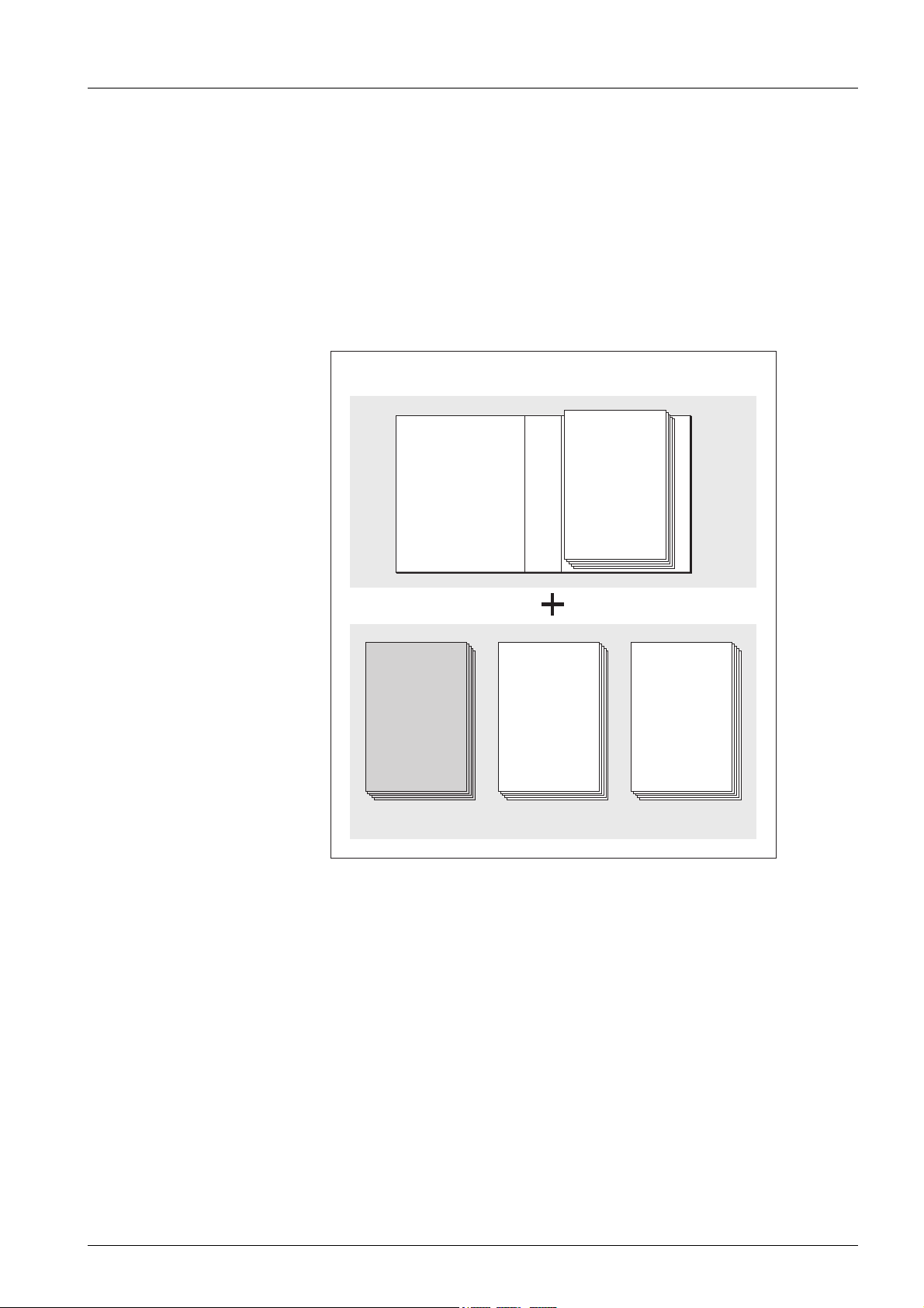
IQ Sensor Net Operating Manual
System
Operating
Manual
(Ring Binder)
IQ Sensor
Operating
Manual
MIQ Module
Operating
Manual
MIQ Terminal
Operating
Manual
Component Operating Manuals
1. Overview
Structure of the
ENSORNET operating
IQ S
manual
1.1 How to use this component operating manual
Fig. 1-1: Structure of the IQ SENSORNET operating manual
The IQ SENSORNET operating manual has a modular structure like the
ENSORNET system itself. It consists of a system operating manual
IQ S
and the operating manuals of all the components used.
Please file this component operating manual into the ring binder of the
system operating manual.
ba76133e01 09/2013 7
Page 8

P 700 IQ
1.2 Metrological basics
Phosphate The salts of the phosphoric acid are called phosphate. With simple
phosphoric acid (orthophosphoric acid, H
3-
(anion PO
).
4
Measuring method The P 700 IQ phosphate analyzer measures the concentration of
orthophosphate in an aqueous solution with the aid of the vanadate
molybdate method (yellow method).
The reagent contains an aqueous solution of ammonium metavanadate NH
addition of sulfuric acid H
and ammonium heptamolybdate (NH4)6Mo7O24 with an
4VO3
. In an acidic environment, the chemical
2SO4
reaction takes place according to the following molecular formula:
) this is orthophosphate
3PO4
PO
3-
+ 2 VO
4
-
+ 10 MoO
3
2-
+ 20 H+ → [PV2Mo10O40]5- + 10 H2O
4
The originally pale yellow reagent will turn a deep yellow. The change
of absorbance is photometrically measured at a wavelength of 420 nm.
From this, the concentration of orthophosphate is calculated.
Citation forms Phosphate concentration is quoted in milligrams per liter (mg/l). This
value can either refer to all orthophosphate ions or only to the phosphorus atom included. The values can be converted as follows:
• 1 mg P = 3.066 mg PO4
• 1 mg PO4 = 0.3261 mg P
Concentration values referring to the phosphorus atom are indicated by
the addition PO4-P (citation form).
8 ba76133e01 09/2013
Page 9

P 700 IQ
2
1
3
4
5
6789
Instrument design Fig. 1-2, 9 shows the mains components of the P 700 IQ.
1.3 Product description
1.3.1 Overview
The P 700 IQ analyzer is designed for online measurements of the
orthophosphate concentration (PO4) in aqueous samples, especially
for phosphorus elimination in waste water treatment plants. Measurement takes place photometrically, at adjustable intervals.
Fig. 1-2: Main components of the P 700 IQ
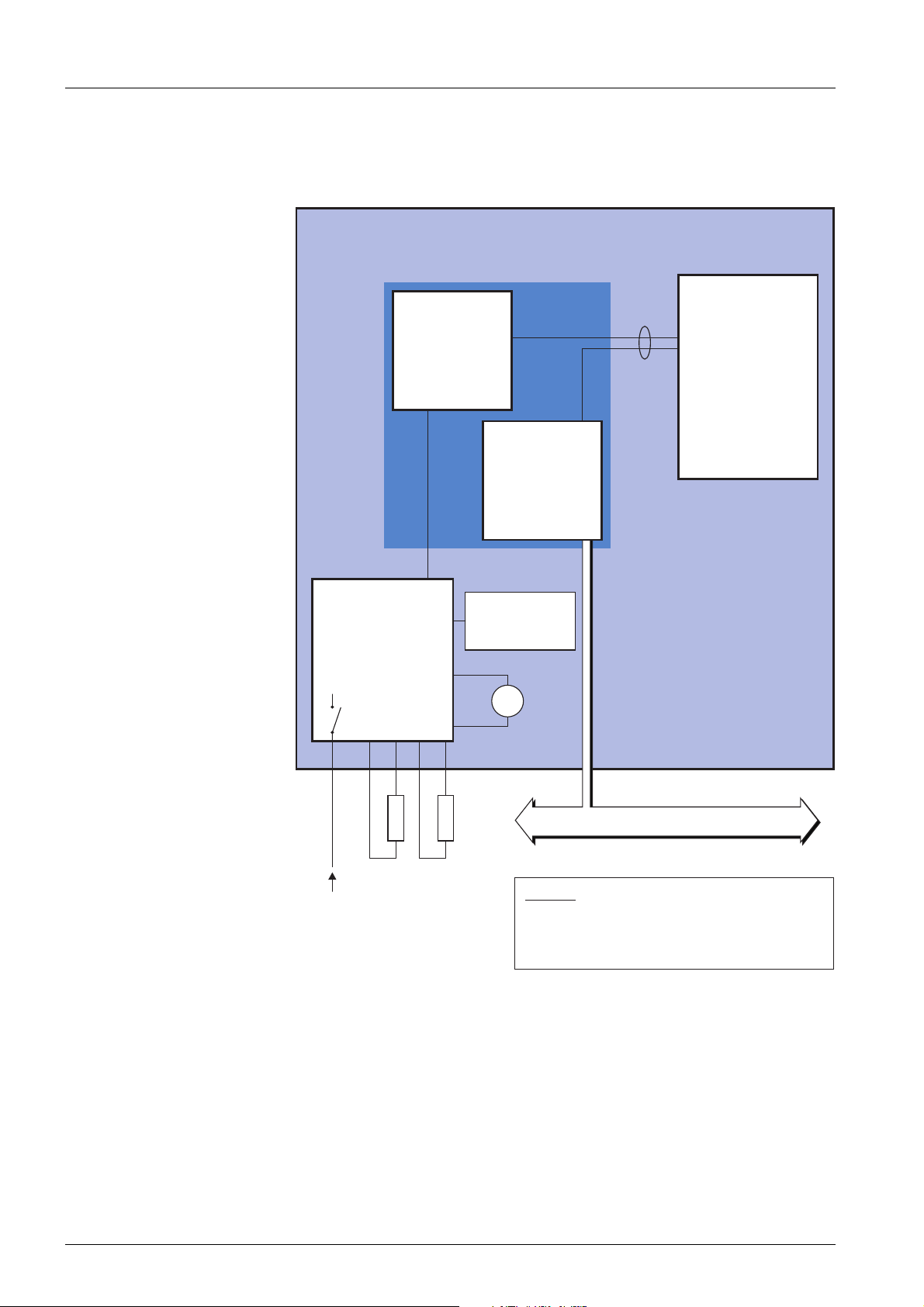
1 Power supply unit for the photometer unit
2IQSENSORNET interface MIQ/WCA 232
3 Photometer unit P700IQ-PO4
4 Power supply box
5 Filtration pump (instrument option)
6 Overflow vessel
7 Cleaning solution
ba76133e01 09/2013 9
8 Standard solution
9 Reagent
Page 10
P 700 IQ
15 V DC
RS 232
Analyzer P 700 IQ
P700IQ-PO4
Photometer unit
(Options)
(Option “P“)
H1
Line voltage
input
P
F
H2
IQ Sensor Net (data + power)
e.g. SN 12500005
e.g. SN 13030003
Power supply box
PS15V
e.g. SN 12500258
MIQ/WCA 232
IQ Sensor Net
interface
Overload protection
Line filter
On/Off
Power supply unit
e.g. SN 12500258
Climate kit
(option “O“)
Outputs
Legend:
P Filtration pump
H1 Heat tracing for feed line
H2 Heat tracing for permeate return line
F
Power supply and
communication
Fig. 1-3, 10 shows the power supply and communication interfaces
of the P 700 IQ.
Fig. 1-3: Block diagram P 700 IQ
Operation The P 700 IQ is operated with a terminal on the IQ SENSORNET. It is
connected to the IQ S
ENSORNET through the MIQ/WCA 232 interface.
For more ease of use while maintenance activities are being carried out
on the open analyzer, a mobile terminal can be docked onto the lid of
the MIQ/WCA 232. The MIQ/WCA 232 interface is supplied with power
by the IQ S
ENSORNET.
10 ba76133e01 09/2013
Page 11
P 700 IQ
V8
2
NO
3
NC
V7
V11
VK6
VK5
Currentless path, filled
1
C
V8 V7
V11
VK6
VK5
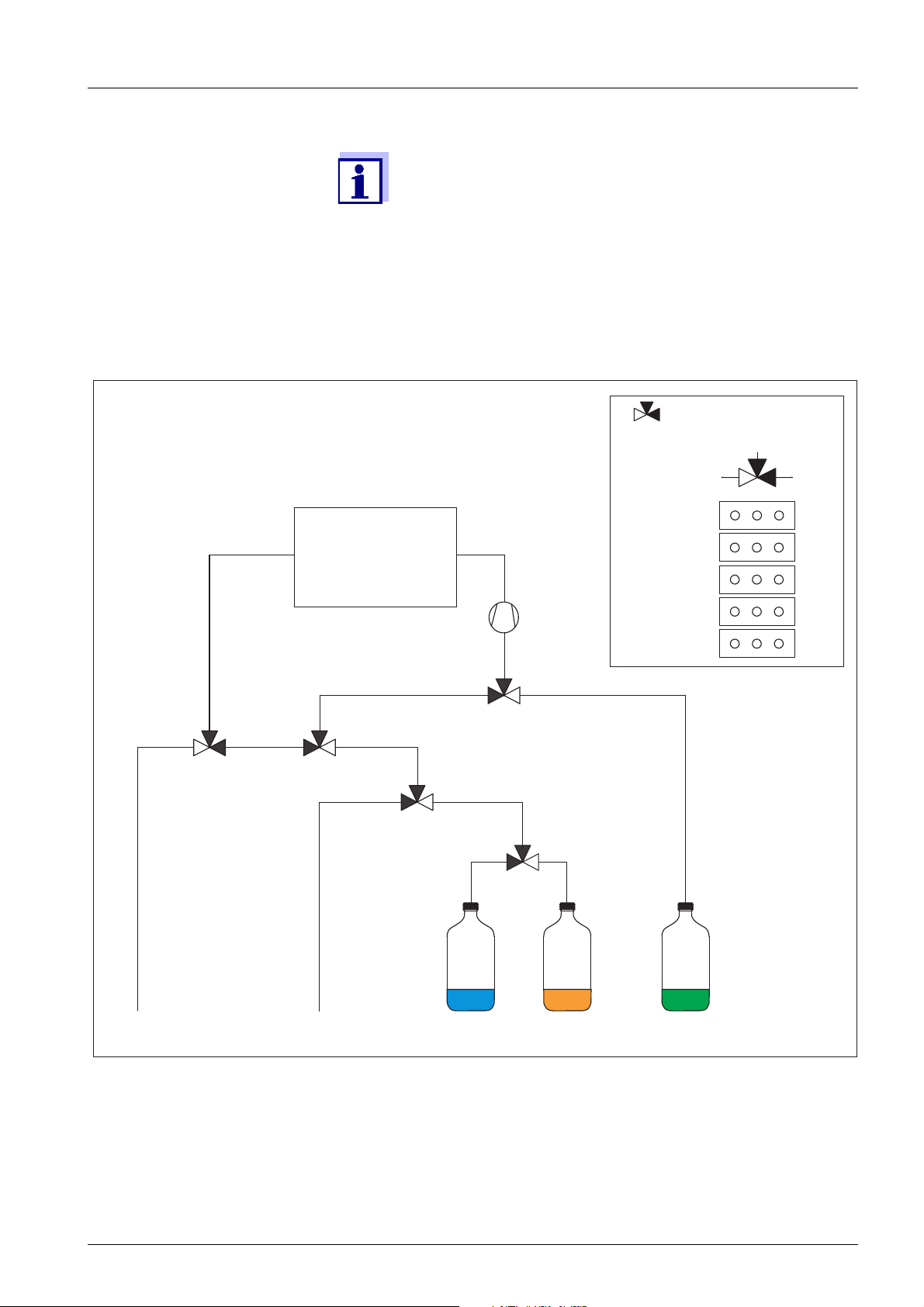
Cleaning
solution
Standard
solution
Reagent
solution
Blue
Orange
Green
Optical block
Valve block
SampleOutlet
Peristaltic
pump
P700IQ-PO4
Information on IQ SENSORNET terminals is given in the relevant IQ S
ENSORNET system operating manual.
1.3.2 Photometer unit
Fig. 1-4, 11 shows the hydraulic system of the P700IQ-PO4
photometer unit.
Fig. 1-4: Hydraulic system
ba76133e01 09/2013 11
Page 12

Fig. 1-5, 12 shows the photometer unit installed.
1
3
4
5
2
7
6
P 700 IQ
Fig. 1-5: Photometer unit without plastic cover
1 Controller housing
2 Status LED
3 Optical block
4 Joint connection cable for supply voltage and communication
5 Overflow vessel
6 Valve block with inlet and outlet tubes
7 Peristaltic pump
How it functions The photometer unit is supplied with d.c. voltage by the PS15V power
pack and operated by a controller (1). It communicates with the
ENSORNET through the MIQ/WCA 232 interface.
IQ S
In conjunction with the peristaltic pump (7), the valve block (6) controls
the movement of the liquids (sample, reagent, standard solution, cleaning solution).
The photometer unit draws the sample from the overflow vessel (5). Filtrated sample continuously flows through the overflow vessel. Thus the
sample is constantly available and free of air bubbles. The filtration unit
(available as an accessory) in conjunction with the filtration pump
(instrument option "P“) provides an optimally prepared sample.
The absorbance of the reaction mixture is measured in the optical block
(3). The optical block has an LED as the light source and photo diodes
as a detector. After the measurement, the liquid is removed from the
optical block.
12 ba76133e01 09/2013
Page 13

P 700 IQ
P 700 IQ-(P)X123
12 3
Options
1.3.3 Status LED
The status LED on the controller enclosure indicates the current operating condition:
LED Meaning
Off No power supply
green The P700IQ-PO4 photometer unit is ready for operation
and waiting for the next action.
red The photometer unit is performing an action.
Tab. 1-1: Conditions of the status LED
1.3.4 Instrument options
The P 700 IQ analyzer is available with different options. The options
installed are quoted in the type designation on the name plate:
Fig. 1-6: Structure of the type designation
Option
1 P With filtration pump
2 I Without climate kit (“Indoor“)
3 115 Input voltage 115 V AC
Identification /
value
(without) Without filtration pump
O With climate kit (“Outdoor“)
Option
Filtration pump
(instrument option “P“)
ba76133e01 09/2013 13
Tab. 1-2: Explanation of the option identifiers in the type designation
The filtration pump is optimally adjusted to the sample filtration available as an accessory.
Page 14

P 700 IQ
1
2
4
5
6
3
7
Fig. 1-7, 14 shows the filtration pump in the P 700 IQ analyzer.
Climate kit
(instrument option “O“)
Fig. 1-7: Filtration pump
1 Control panel with pump frequency indication
2 Intake tube of the sample filtration (accessory, see section 1.3.6,
3 Connection tube
4 Overflow vessel
5 Outlet of the overflow vessel
6 Return tube (accessory, see section 1.3.5,
7 Manometer
15)
15)
The filtration pump continuously draws sample through the intake tube
(2) and pumps it into the overflow vessel (4) through the connection
tube (3). The flow rate can be set on the control panel (1). On the intake
side, a manometer (7) is installed for low pressure measurement.
For sample preparation, a sample filtration device (available as an
accessory) can be connected upstream.
The climate kit includes an electrical circulating air heating, two housing
ventilators and three temperature regulators. The temperature regulators switch on the heating or ventilators if the temperature is less than
+15 °C or more than 40 °C. Thus the analyzer with the door closed is
suitable for all-season operation in the open. The climate kit is automatically active when the switch on the power supply box is in the ON position.
Where there is a chance of frost, the intake tube and return
14 ba76133e01 09/2013
tube must be provided with a heat tracing.
Page 15

P 700 IQ
2
1
3
6
5
4
1.3.5 Return tube (accessory)
The return tube directs out of the analyzer housing the overflowing
sample from the overflow vessel and the waste solution from the photometer unit. Return tubes with heat tracing are available for frost protection.
Order information referring to accessories is given in
chapter 5.2 Consumables, accessories, replacement parts,
65.
1.3.6 Sample filtration device (accessory)
To separate the particles in the sample, the FM filter membrane module
is available as an accessory. It is connected to the analyzer with a suction line. The filtered sample is drawn by the filtration pump in the analyzer (instrument option "P“).
The FM filter membrane module consists of a separable housing and
two membrane inserts. With the aid of the M 1.5 attachment for filtration, the FM filter membrane module can be immersed in the measuring
medium and can be adjusted in height. To clean the membrane inserts,
the filter membrane module can be pulled out along a guide rail with a
chain.
The suction line consists of a suction tube in a robust sleeve tube. Suction lines are available in different lengths and, as frost protection, with
heat tracing.
Fig. 1-8, 15 shows an application example in a sedimentation tank.
Fig. 1-8: Sample filtration device (installed)
1 Chain (scope of delivery: Attachment for filtration M 1.5)
2 Guide rail (scope of delivery: Attachment for filtration M 1.5)
ba76133e01 09/2013 15
3 Height adjustable slide (scope of delivery: Suction line)
4 Suction line (scope of delivery: Suction line)
5 Sleeve tube (scope of delivery: Suction line)
6 Filter membrane module FM with membrane insert
Page 16
P 700 IQ
Order information referring to accessories is given in
chapter 5.2 Consumables, accessories, replacement parts,
65.
1.4 Name plates
The following components have name plates:
Component Place of the name plate
Total analyzer In the right-hand bottom edge on
the inside of the housing door
ENSORNET interface
IQ S
MIQ/WCA 232
Photometer unit P700IQ-PO4 On the left side of the controller
Power supply unit for the PS15V
photometer unit
Tab. 1-3: Name plates
Keep the series numbers on the name plates ready for any
service requests.
On the right side of the
MIQ/WCA 232
housing of the photometer unit
On the right side of the PS15V
16 ba76133e01 09/2013
Page 17
P 700 IQ
2. Safety instructions
2.1 Safety information
2.1.1 Hazard warnings in this operating manual
The hazard warnings are defined for the following levels of danger:
WARNING
WARNING indicates a possibly dangerous situation that
can cause death or serious injuries if the safety instruction is not followed.
CAUTION
CAUTION indicates a possibly dangerous situation that
can cause slight or medium injuries if the safety instruction is not followed.
ATTENTION
ATTENTION indicates a situation where goods might be
damaged if the actions mentioned are not taken.
2.1.2 Safety information on the product
Note all labels, information signs and safety symbols on the product.
2.1.3 Labels on the chemical containers
Note the labeling on the chemical containers, especially the hazard and
safety information.
ba76133e01 09/2013 17
Page 18

P 700 IQ
2.1.4 Safety datasheets of the chemicals
Safety datasheets provide security relevant information on hazardous
materials and mixtures. Carefully read the safety datasheets and follow
all instructions. We recommend storing all datasheets in one folder.
2.2 Safe operation
2.2.1 Authorized use
The authorized use of the P 700 IQ phosphate analyzer comprises its
use as a sensor in the IQ S
of the analyzer according to the instructions and technical specifications given in this operating manual is authorized (see chapter 7. Technical data, 99). Any other use is considered unauthorized.
ENSORNET. Only the operation and running
2.2.2 Requirements for safe operation
Note the following points for safe operation:
• The product may only be operated according to the authorized use
specified above.
• The product may only be supplied with power by the energy sources
mentioned in this operating manual.
• The product may only be operated under the environmental conditions mentioned in this operating manual.
• The product or its components may only be opened if this is required
for installation and maintenance work and described in the operating
manual.
2.2.3 Unauthorized use
The product must not be put into operation if:
• it is visibly damaged (e.g. after being transported)
• it was stored under adverse conditions for a lengthy period of time
(storing conditions, see chapter 7 Technical data)
18 ba76133e01 09/2013
Page 19
P 700 IQ
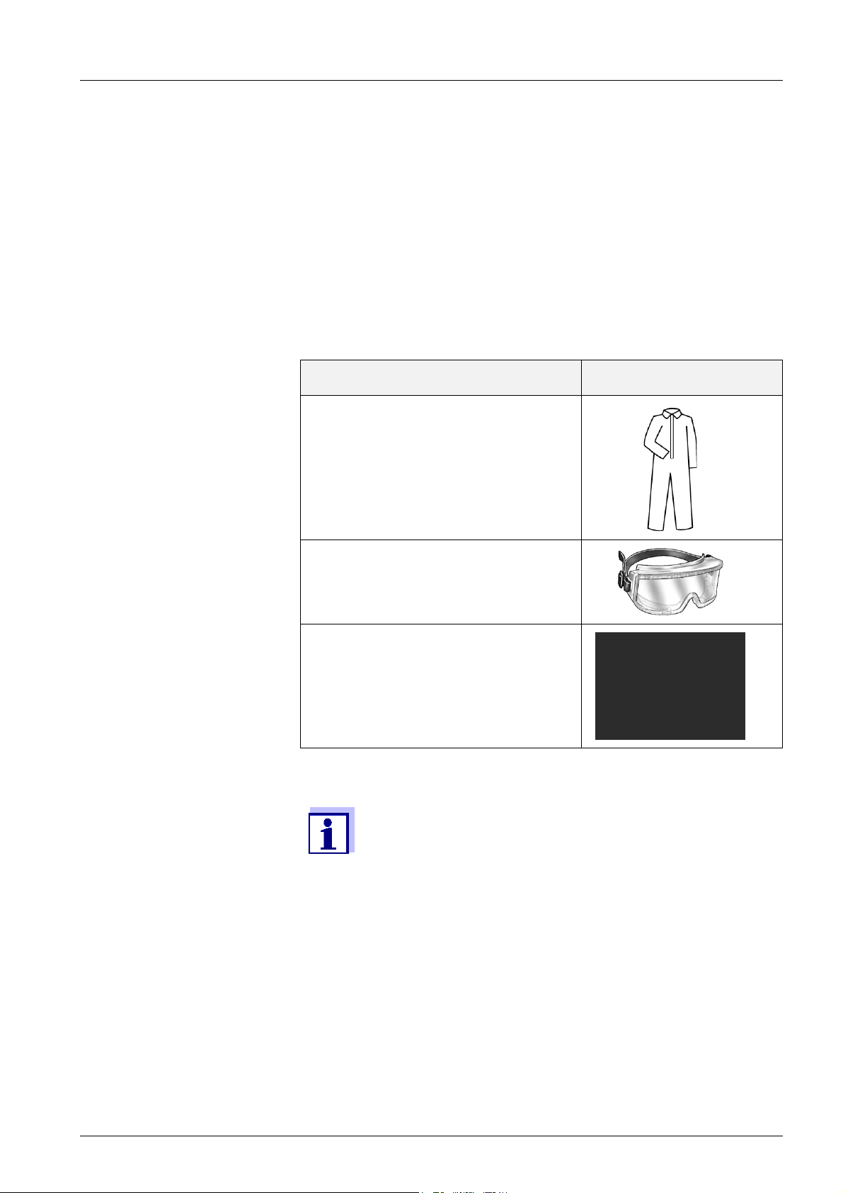
2.3 Personal protective equipment (PPE)
The PPE includes clothing and other equipment that is used to protect
you against risks at your place of work. You must always wear your
PPE while doing dangerous jobs to avoid injuries or damage to your
health.
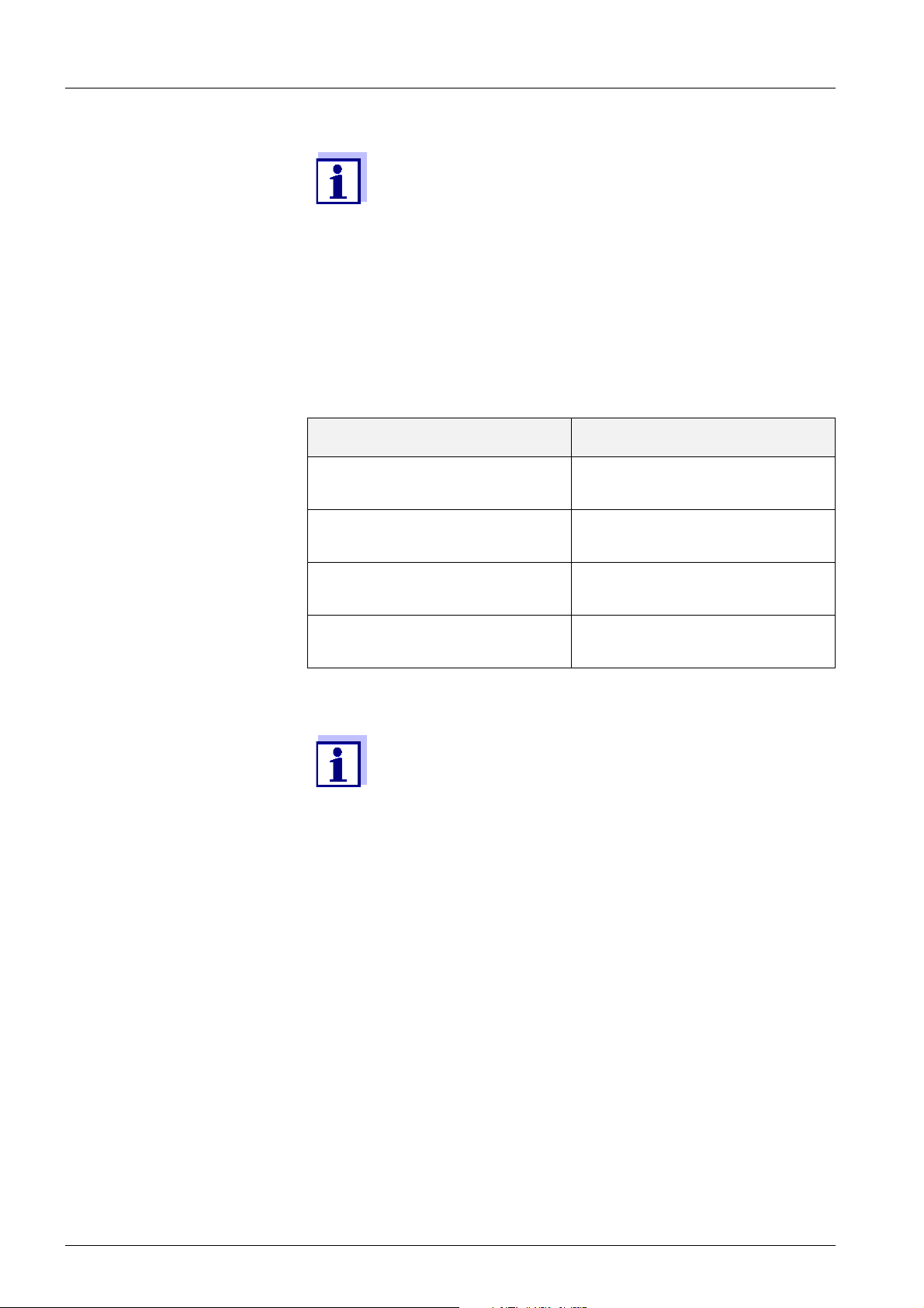
The following table shows the PPE that is required while dealing with
dangerous chemicals such as when exchanging the chemical containers. More information is given on the label of the chemical containers
and the relevant safety datasheets.
Personal protective equipment Typical examples
Protective clothing with long sleeves
Protective goggles
Chemical resistant gloves
Tab. 2-1: Personal protective equipment
It is the duty of the operator to provide all users with the
required PPE. The PPE must fulfill the national standards
and laws.
ba76133e01 09/2013 19
Page 20

P 700 IQ
20 ba76133e01 09/2013
Page 21

P 700 IQ
3. Commissioning
3.1 IQ SENSORNET system requirements
Software statuses of the
controller and terminal
components
The operation of the P 700 IQ requires the following software versions
in the IQ S
MIQ/MC2 Controller software: Version 3.39 or higher
MIQ/TC 2020 XT Terminal software: Version 3.39 or higher
ENSORNET:
3.2 Scope of delivery
3.2.1 P 700 IQ scope of delivery
The following parts are included in the scope of delivery of the
P 700 IQ:
• Housing with mounted and wired installations including instrument
options
• Key for outer housing door
• Switch cabinet key for interior door
• Screwdriver for MIQ/WCA 232
• Mounting aid for pump tube
• Chemicals tray
• Lid set for chemicals
• Operating manual
Check whether the scope of delivery is complete before starting the
installation.
The power line is not included in the scope of delivery.
ba76133e01 09/2013 21
Page 22

P 700 IQ
3.2.2 Accessories required in addition
Depending on the application, the following additional accessories are
required or recommended for operation. We explicitly recommend
using original YSI accessories:
Mounting accessories Ensure the safe fastening at the mounting location. The following vari-
ants are available:
• Rail mount RM
• Wall mount WM
• Stand mount SM
Chemicals • Reagent solution RE 2.5
Sample preparation
(filtration)
• Cleaning solution CL 1.0
• Standard solutions ST ... (depending on measuring range and cali-
bration procedures)
• Filter membrane module FM
• Attachment for filtration M 1.5 for filter membrane module FM, also
available with extension M-EXT 1.5
• Suction line SL ... (different lengths up to 20 m, with and without heat
tracing)
• Return tube RL ... (different lengths up to 20 m, with and without
heat tracing)
Order information referring to accessories is given in
chapter 5.2 Consumables, accessories, replacement parts,
65.
22 ba76133e01 09/2013
Page 23

P 700 IQ
3.3 Installation
3.3.1 General installation instructions
This section describes the installation of the P 700 IQ with
various especially designed accessories. We assume that
the operator uses these accessories. In this section, the
individual scopes of delivery are not distinguished so the
comprehensibility of the instructions is not affected.
Pay attention to the following points during installation:
• Installation in the open should be done while the weather is frost-
free.
• Due to its weight, the analyzer always has to be carried by two
people (housing door upward, both people grasp the housing at the
upper C rail and at the housing bottom on the side of the door).
• The analyzer may only be fastened on a wall or fixture with the aid
of the two rails (enclosure upright).
Main steps Installation of the P 700 IQ includes the following main steps:
1 Installing the housing.
See section 3.3.2, 24.
2 Installing the FM filter membrane module and the
M 1.5 attachment for filtration.
See section 3.3.3, 35.
3 Inserting the connections into the housing.
See section 3.3.4, 36.
4 Connecting the IQ S
See section 3.3.5.1, 39.
5 Connecting the power line and heat tracing lines.
See section 3.3.5.2, 40.
6 Connecting the liquid containers.
See section 3.3.5.3, 42.
ENSORNET cable.
ba76133e01 09/2013 23
Page 24

Assembling the stand
1
2
(2 x)
3
mount
P 700 IQ
3.3.2 Installing the housing
The housing of the P 700 IQ can be installed in the following ways:
• On the SM stand mount. See section 3.3.2.1 Installation on the SM
stand mount, 24.
• On a rail. See section 3.3.2.2 Installation on a rail, 29.
• On a wall. See section 3.3.2.3 Installation on a wall, 33.
3.3.2.1 Installation on the SM stand mount
Proceed as follows to install the housing on the stand mount:
Fig. 3-1: Mounting the ground pipes
1 Press the plastic protective plugs (1) into both ends of the square
ground pipes (2).
2 Mount the four height adjustable stand feet (3) on the square
ground pipes (2) using the enclosed M10 hexagon countersunk
head screws. Make sure to use the correct number of plain washers and nuts in the correct order according to Fig. 3-1, 24.
24 ba76133e01 09/2013
Page 25

P 700 IQ
1
4
5
2
Fig. 3-2: Connecting the supporting pipes with the ground pipes
3 Press the plastic protective plugs (1) into the upper ends of both
square supporting pipes (4).
4 Using the triangular stabilizing sheets (5), connect both square
supporting pipes (4) with the preassembled ground pipes (2). To
do so, use a total of six M8 hexagon head screws with large M8
plain washers and locknuts as shown in Fig. 3-2, 25. Make
sure the two columns mirror each other after being mounted.
ba76133e01 09/2013 25
Page 26
P 700 IQ
67
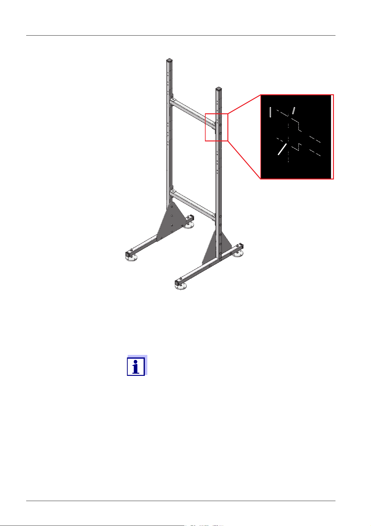
Fig. 3-3: Connecting the supporting pipes with the cross pipes
5 Connect both supporting pipes with each other using the two
square cross pipes (6). To do so, use the eight angle brackets (7)
and a total of twelve M8 hexagon head screws with plain washers
and locknuts.
Make sure that both triangular stabilizing sheets (5) are on
the inside.
6 Mount the four retaining hooks (8) on the stand mount. To do so,
use a total of twelve M8 hexagon head screws with large M8 plain
washers and locknuts.
26 ba76133e01 09/2013
Page 27
P 700 IQ
8
Positioning the stand
mount
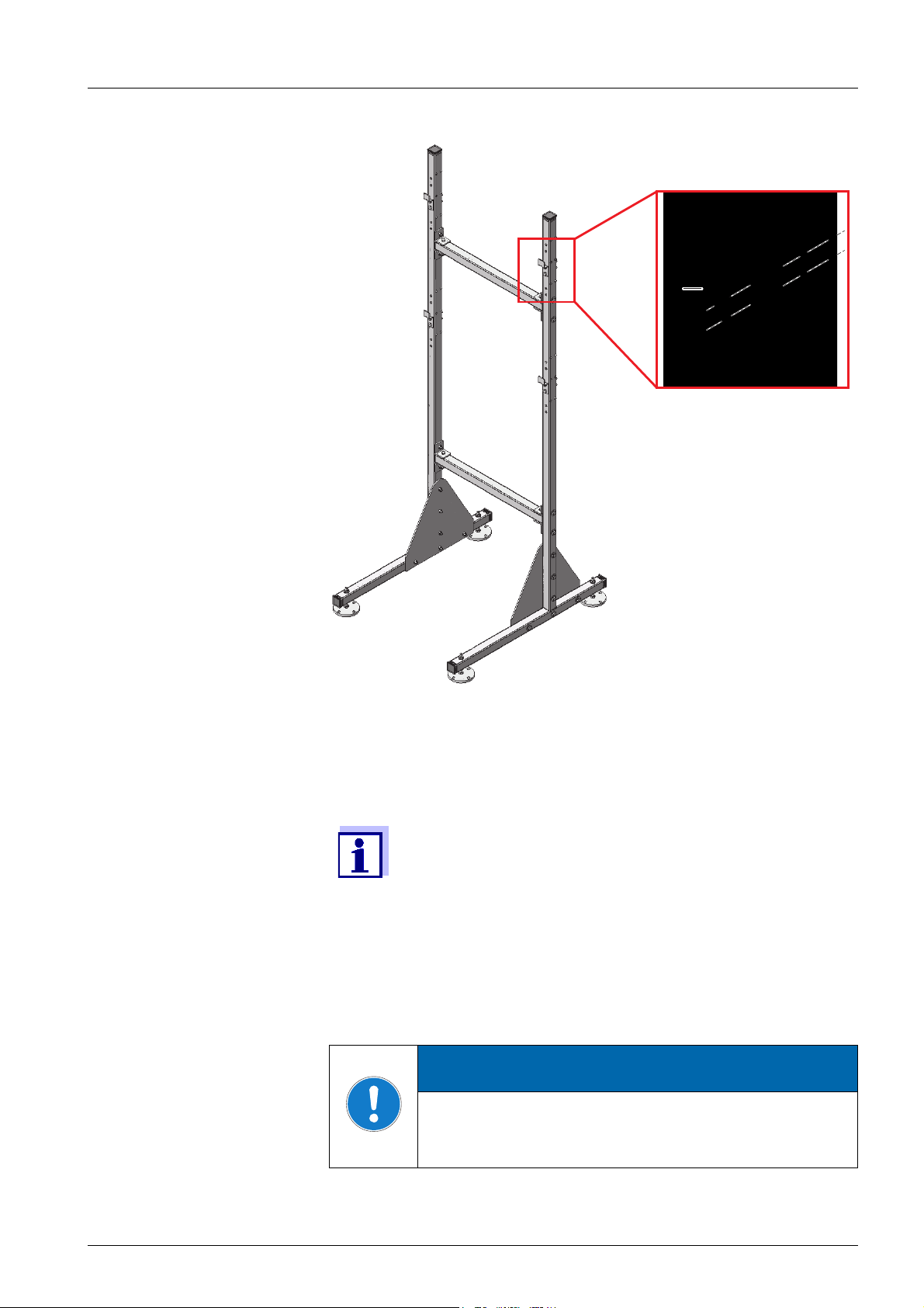
Fig. 3-4: Mounting the retaining hooks
7 Mount the four retaining hooks (8) on the stand mount. To do so,
use a total of eight M8 hexagon head screws with large M8 plain
washers and locknuts.
There are three pairs of holes each for the upper and lower
retaining hooks. Thus the analyzer can be mounted optimally at working level. Use the same relative positions for
each of the upper and lower hooks.
8 Place the stand mount at the intended operating location.
9 Adjust the four height adjustable stand feet so that the stand
mount stands straight.
ATTENTION
Always screw the four stand feet to the ground. With
installation at an open air test site, make sure that the
installation will also hold out against strong storms.
ba76133e01 09/2013 27
Page 28
Mounting the housing
10
9
11
P 700 IQ
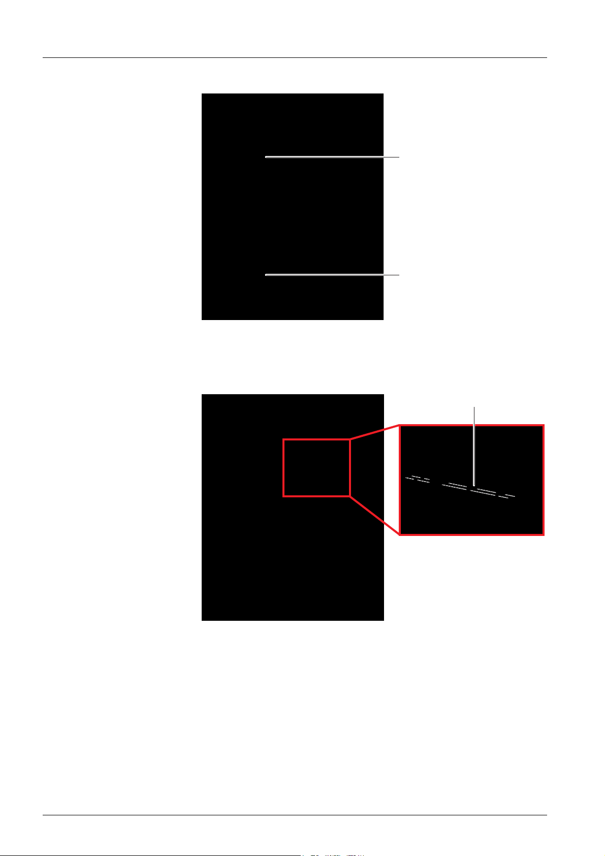
Fig. 3-5: Mounting the housing
10 Mount the housing by hooking the rails (9 and 10) fixed on its rear
side into the retaining hooks of the stand mount.
Fig. 3-6: Fixing the housing
11 Fix the housing on both sides with the 4 mounting brackets (11)
so it cannot shift sideways. To do so, use a total of eight M8 hexagon head screws with small M8 plain washers and locknuts.
28 ba76133e01 09/2013
Page 29
P 700 IQ
1
2
34
3.3.2.2 Installation on a rail
For installation on a rail, the RM rail mount bracket is required.
ATTENTION
Make sure that the rail is sufficiently stable. With installation at an open air test site, make sure that the installation will also hold out against strong storms.
Assembling the bracket Proceed as follows to install the housing on the rail:
Fig. 3-7: Connecting the supporting pipes with the cross pipes
1 Press the plastic protective plugs (1) into the upper ends of both
square supporting pipes (2).
2 Connect both supporting pipes with each other using the two
square cross pipes (6). To do so, use the eight angle brackets (7)
and a total of twelve short M8 hexagon head screws with large
plain washers and locknuts.
ba76133e01 09/2013 29
Page 30
P 700 IQ
5
Fig. 3-8: Mounting the retaining hooks
3 Mount the four retaining hooks (5) on the rail mount. To do so,
use a total of eight short M8 hexagon head screws with small M8
plain washers and locknuts.
There are three pairs of holes each for the upper and lower
retaining hooks. Thus the analyzer can be mounted optimally at working level. Use the same relative positions for
each of the upper and lower hooks.
30 ba76133e01 09/2013
Page 31

P 700 IQ
9
6
7
8
Fixing the rail mount
bracket
4 Place the rail mount bracket in front of the rail in the required posi-
tion.
Fig. 3-9: Mounting the rail mount bracket on the rail
5 Attach the rail mount bracket to two suitable horizontal rail pipes
with the aid of the four clamps. Each clamp consists of 2 slot bars
(6), 2 long hexagon head screws M8x80 (7), 2 nuts (8) and 2
spring washers (9). Adjust the positions of the clamps to the rail
pipes. Note that the rail mount bracket must still stand on the
ground!
The weight of the analyzer is supported by the rail mount
bracket standing on the ground. The rail prevents the analyzer from tilting over.
ba76133e01 09/2013 31
Page 32

Mounting the housing
8
7
9
P 700 IQ
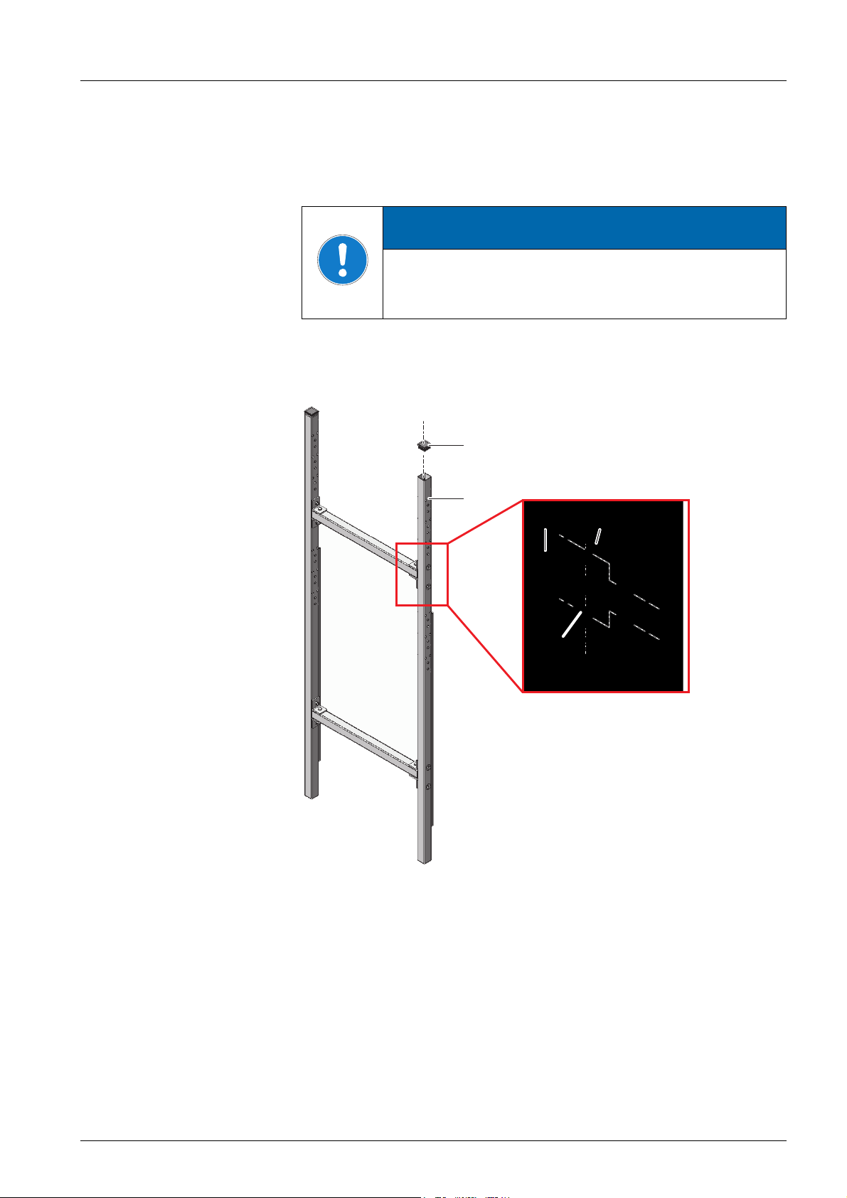
Fig. 3-10: Mounting the housing
6 Mount the housing by hooking the rails (7 and 8) fixed on its rear
side into the retaining hooks of the rail mount bracket.
Fig. 3-11: Fixing the housing (on the right: Detailed view)
7 Fix the housing on both sides with the 4 mounting brackets (9) so
it cannot shift sideways. To do so, use a total of eight short M8
hexagon head screws with plain washers and locknuts.
32 ba76133e01 09/2013
Page 33

P 700 IQ
540
408
30
Recommended height above the ground approx. 165 m
3.3.2.3 Installation on a wall
With the rails on its rear side, the analyzer is hooked into the in die
retaining hooks of the WM wall mounting set.
ATTENTION
Make sure that the wall is strong enough for the weight
of the analyzer and that the mounting material (screws,
plugs, etc.) is suitable for the wall type. If necessary, use
other screws and plugs than the ones provided.
Proceed as follows to install the housing on a wall:
1 Drill eight holes as shown in the following figure:
Fig. 3-12: Drilling dimensions for mounting the WM wall mount
2 Screw tight the four retaining hooks of the wall mounting set.
3 Mount the housing by hooking the rails fixed on its rear side into
the retaining hooks. The fixing screws of the rail must be outside
the retaining hooks on both sides as shown in the following figure:
ba76133e01 09/2013 33
Page 34

P 700 IQ
2
1
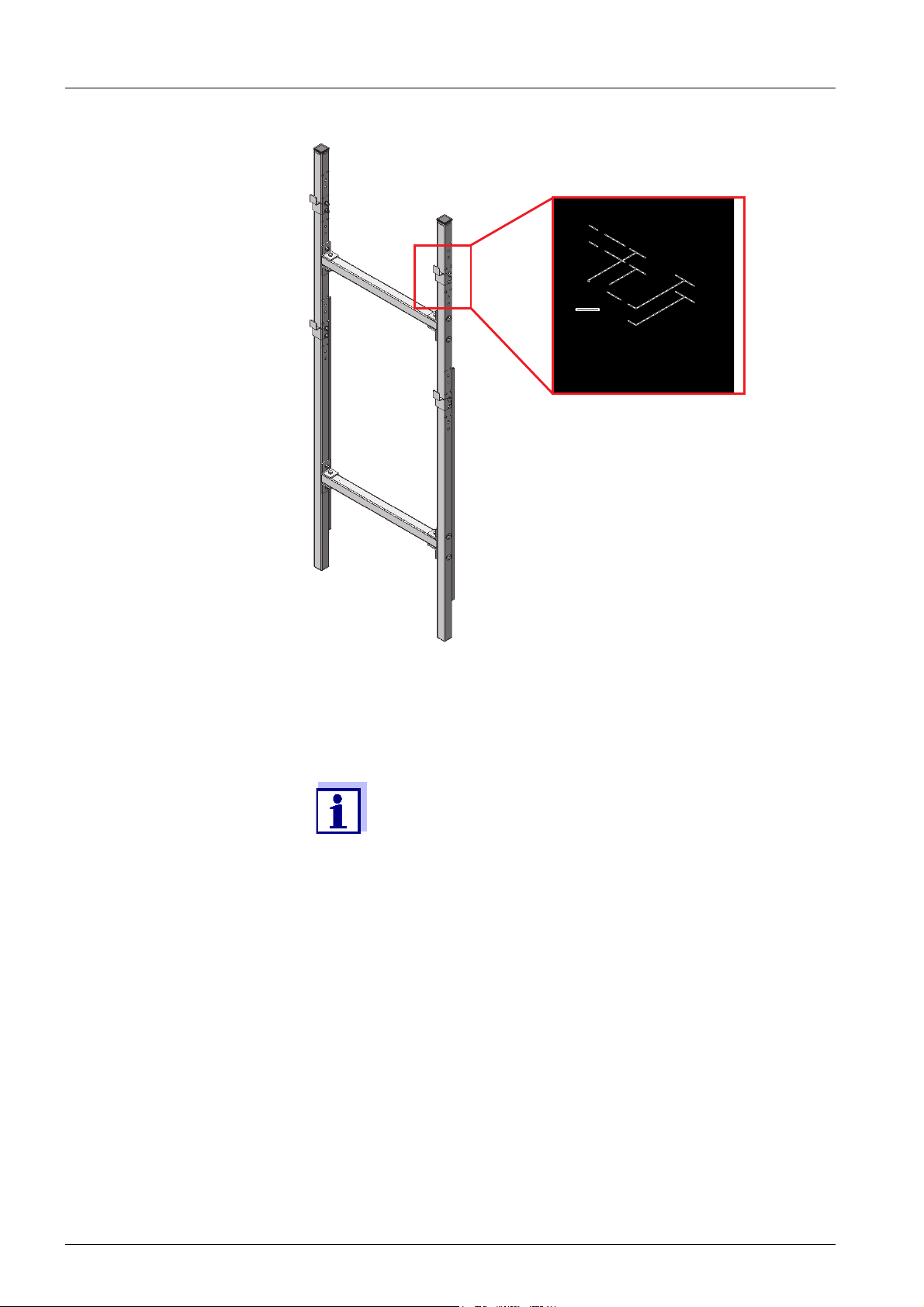
Fig. 3-13: Analyzer housing in the WM wall mounting assembly.
1 Retaining hook
2 Fixing screws of the rail
34 ba76133e01 09/2013
Page 35

P 700 IQ
2
1
3
6
5
4
3.3.3 Installing the FM filter membrane module and the
M 1.5 attachment for filtration
Installation instructions Heed the following notes when installing the filter membrane module:
• Mount the filter membrane module so that the plate is in a position
vertical to the flow direction.
In special cases (e.g. in a channel) it is better to mount the
FM filter membrane module in a position horizontal to the
flow direction.
An adapter for horizontal mounting is available as an
accessory.
• The filter membrane module and the slide must be completely sub-
mersed (max. 40 cm).
Take changing water levels into account when mounting the filter
membrane module.
• The lower edge of the filter membrane module must be mounted
with least 10 cm distance to the bottom.
Installation 1 Mount the rail of the attachment for filtration in the basin. If nec-
essary, extend the rail with the
M-EXT 1.5 extension accessory.
Fig. 3-14: Sample filtration device (installed)
1 Chain (scope of delivery: Attachment for filtration M 1.5)
2 Guide rail (scope of delivery: Attachment for filtration M 1.5)
3 Height adjustable slide (scope of delivery: Suction line)
4 Suction line (scope of delivery: Suction line)
5 Sleeve tube (scope of delivery: Suction line)
6 Filter membrane module FM with membrane insert
2 Mount the filter membrane module on the slide of the attachment
ba76133e01 09/2013 35
for filtration.
3 Connect the suction line to the filter membrane module.
Page 36

P 700 IQ
4 Insert the slide of the filter membrane module in the rail and lower
it into the basin with the aid of the chain. Fix the end of the chain
outside the basin.
5 Run the suction line to the analyzer. Fix the line with cable ties at
some suitable places as necessary. How to connect the suction
line to the P 700 IQ, see section 3.3.4, 36.
3.3.4 Inserting the connections into the housing
Connection plate All connections are inserted into the housing through dust-proof lead-in
ducts. The lead-in ducts are on a connection plate in the bottom of the
housing. The connection plate can be removed for the mounting of the
tubes.
1 Unscrew the connection plate from the bottom of the housing.
Connecting the filter
unit and return tube
(accessories)
2 Run the power line through the small cable gland on the left. Fix
the power line only slightly for the time being so that it can be
readjusted later.
3 Run the IQ S
Fix the IQ S
ENSORNET cable through the small rear cable gland.
ENSORNET cable only slightly for the time being so
that it can be readjusted later.
If the IQ S
MIQ/WCA 232, insert the IQ S
ENSORNET should be further branched at the
ENSORNET cable leading
away through the small front cable gland.
4 Run the suction line through the big cable gland on the left side
of the connection plate.
• The sleeve tube should stick out approx. 5 cm behind the connection plate.
• Fix the sleeve tube with the cable gland.
5 Run the return tube through the big cable gland on the right side
of the connection plate.
• The sleeve tube should stick out approx. 5 cm behind the connection plate.
• Fix the sleeve tube with the cable gland.
36 ba76133e01 09/2013
Page 37

P 700 IQ
12
4
5
3
Fig. 3-15: Connection plate on the underside of the housing
1 Power line
2 Sleeve tube of the suction line
3 Lead-in duct for the IQ SENSORNET branching (option)
ENSORNET cable
4IQS
5 Sleeve tube of the return tube
6 Screw the connection plate with the preassembled tubes to the
bottom of the housing again. See Fig. 3-15, 37.
All open cable glands must be closed with suitable plugs.
ba76133e01 09/2013 37
Page 38

P 700 IQ
12
3
4
6
57
3.3.5 Connecting the lines
Fig. 3-16, 38 shows the housing with the completely connected lines
including the accessories and all options:
Fig. 3-16: Completely connected lines
1 Power line
2 Intake tube
3 Heat tracing of the suction line (option)
4 Heat tracing of the return tube (option)
5IQSENSORNET cable
6 Outlet of the overflow vessel
7 Outlet of the photometer unit
Proceed as follows to connect the individual lines:
1 Connect the intake tube (2) to the filtration pump.
2 Insert the outlet of the overflow vessel and the outlet of the pho-
tometer unit into the sleeve tube of the return tube.
The liquid from the return tube must be able to drain off
freely (downward slope).
3 Connect the IQ S
section 3.3.5.1 Connecting the IQ S
ENSORNET cable to the MIQ/WCA 232. See
ENSORNET cable, 39.
4 Connect the power line (1) and, if necessary, the heat tracing
lines (3 and 4) to the power supply box. See section 3.3.5.2 Connecting the power line and heat tracing lines, 40.
5 Tighten all cable glands after the connections have been made.
38 ba76133e01 09/2013
Page 39

P 700 IQ
SENSORNET 2
SENSORNET 1
SACIQSNCIQ
SNCIQ/UG
2
1
X6 X5 X4
SENSORNET 2
RED
SHIELD
GREEN
X3 X2 X1
SENSORNET 1
RED
SHIELD
GREEN
ON
OFF
SN TERMINATOR
3.3.5.1 Connecting the IQ SENSORNET cable
To connect the MIQ/WCA 232 to the IQ SENSORNET, use the outward
right-hand connector of the terminal strip (“SENSORNET 1“). The connection left of this one can be used for branching (“SENSORNET 2“).
Detailed information on the connection of the
ENSORNET cable to the MIQ/WCA 232 and on branch-
IQ S
ing is given in the respective IQ S
ating manual, topic, “distributed mounting“.
ENSORNET system oper-
Fig. 3-17: Terminal strip of the MIQ/WCA 232
1Seal
2 Cable gland
ba76133e01 09/2013 39
Page 40

P 700 IQ
3.3.5.2 Connecting the power line and heat tracing lines
WARNING
If the power supply is connected incorrectly, there may
be danger to life from electric shock.
Pay attention to the following points during installation:
• The power supply box may only be connected to the
power supply by a qualified electrician.
• The power supply box may only be connected to the
power supply when it is not carrying any voltage.
• The power supply must meet the specifications
quoted on the name plate and in chapter chapter 7.
Technical data, 99.
We recommend installing an additional external power
interrupter to be able to switch the power supply box potential free from outside.
Proceed as follows to connect the power line and if necessary the heat
tracing lines:
1 Switch the power line potential free.
2 Set the switch of the power supply box to OFF (0 pressed).
3 Remove the lid of the power supply box.
40 ba76133e01 09/2013
Page 41

P 700 IQ
NL
115 VAC / 16 A
Input
2
1
PE
Heating Line 115 VAC
PE PE N N L L
2
1
3
4
6
5
Fig. 3-18: Power supply box (lines installed)
1 Overcurrent protection
2 Power line
3 Cable gland
4 Heat tracing of the suction line (option)
5 Connecting terminals
6 Heat tracing of the return tube (option)
4 Insert the power line (2) through the cable gland (3).
5 Connect the power line to the overcurrent protection (1) as shown
in Fig. 3-18, 41.
6 Insert the heat tracing lines for the return tube (6, rear) and for the
suction line (4, front) through the cable glands on the right side.
7 Connect the heat tracing lines to the relevant terminals as shown
in Fig. 3-18, 41.
The heating bands of the heat tracing lines must start within
the P 700 IQ analyzer housing to keep the lines frost free.
At the outlet of the return tube, the heat tracing must stick
out 10 to 20 mm. If necessary, shift the heat tracing in the
sleeve tube accordingly.
ba76133e01 09/2013 41
Page 42

P 700 IQ
1
2
3
8 Tighten the cable glands on the power supply box.
9 Mount the lid of the power supply box.
3.3.5.3 Connecting the liquid containers
With installation in the open and ambient temperatures
below 0 °C, make sure that the liquids do not freeze during
the commissioning. If necessary, switch on the power
supply box beforehand and let the housing warm up with
the doors closed (see section 3.4 Initial commissioning,
44).
1 Place the chemicals tray on the bottom of the analyzer.
2 Mount the lids of the lid set on the luer connectors. The lids are
color coded.
3 Put on your personal protective equipment (PPE) and chemical
resistant gloves (see section 2.3 Personal protective equipment
(PPE), 19).
4 Open the lid of the liquid container to be connected.
5 Place the liquid container in the chemicals tray and screw the rel-
evant preassembled lid on the container. The lids with the color
coded connectors are included in the scope of delivery. The color
coding of the container must correspond to the color coding of the
lid (see Fig. 3-19, 42)!
Fig. 3-19: Chemicals container (connected)
1 Color coding of the preassembled lid
2 Color coding of the container
3 Chemicals tray
42 ba76133e01 09/2013
Page 43

P 700 IQ
6 Connect all liquid containers:
• Reagent (green)
• Cleaning solution (blue)
• Standard solution (orange)
Use the calibration standard solution suitable for your measuring range.
Keep the original lids of the containers. They can be
screwed on for disposal.
7 Connect the sample tube.
8 Mount the outlet tube into the return tube.
9 Check whether all other connections are correctly connected
(sample tube connected between overflow vessel and photometer unit, outlet tube inserted in the return tube).
The P 700 IQ has an extra counter for each liquid container
(see chapter 5.4.1 Changing the liquid containers, 76).
In the delivery condition the counters are set to 100%.
ba76133e01 09/2013 43
Page 44

3.4 Initial commissioning
P 700 IQ
Commissioning of the
analyzer
1 Make sure that all liquid containers are correctly connected and
all lines and tubes are correctly installed.
2 Set the switch of the power supply box to ON (I pressed).
Important for operation in the open: If the temperature
inside the enclosure is outside the range +15 ... + 40 °C,
close both enclosure doors and allow the instrument to get
warm for a sufficiently long period of time (provided that
there is a climate kit). Only then proceed with the further
steps. Do not leave the doors open unnecessarily.
3 Use the arrow keys to set the pump capacity to 80 ... 100 %.
Fig. 3-20: Filtration pump
1 Pump capacity in %
2 Arrow keys
3 Start/Stop key
4 Switch on the filtration pump with the Start/Stop key.
5 Wait until sample liquid runs from the overflow vessel into the
return tube. Depending on the length of the intake tube, this may
take some minutes.
44 ba76133e01 09/2013
Page 45

P 700 IQ
1
2
If no sample runs into the overflow vessel, proceed in one
of the following ways:
• Fill the suction line with water manually:
• Switch off the filtration pump.
• Pull the intake tube off the filtration pump.
• Fill the intake tube with water (e.g. using a wash
bottle).
• Connect the intake tube to the pump again and
secure it.
• Switch on the filtration pump.
• Increase the suction power manually:
• At the vent connection (2), connect a syringe with
a tube:
• Open the vent valve (1).
• Create an additional negative pressure with the
syringe.
• Close the vent valve (1).
• Repeat the procedure until sample runs into the
overflow vessel.
• Remove the tube and syringe from the vent connection (2).
Fig. 3-21: Filtration pump
1 Vent valve
2 Vent connection
6 As soon as enough sample is running, reduce the pump power to
5 - 10 % with the aid of the arrow keys.
7 Close the doors of the enclosure.
ba76133e01 09/2013 45
8 If necessary, commission the IQ S
evant IQ S
ENSORNET system operating manual).
ENSORNET system (see the rel-
Page 46

P 700 IQ
Commissioning steps
on the IQ S
ENSORNET
terminal
The following steps are carried out on a terminal in the IQ S
ENSORNET
system. Instructions on operation are given in the respective
ENSORNET system operating manual.
IQ S
9 Using <>, select the P 700 IQ in the measured value display.
10 Using <C>, switch to the calibration and service menu.
The maintenance condition is activated.
11 Confirm the maintenance condition with <OK>.
The calibration and service menu is displayed. See Fig. 3-22,
46.
Starting the
measurement
Fig. 3-22: Calibration and service menu
12 Carry out the Fill the system function.
All tubes of the P700IQ-PO4 are automatically filled with the connected solutions and sample liquid.
13 Follow the instructions on the display.
14 Carry out the Start measuring function.
The measured value determination takes approx. 5… 7 minutes.
A note is displayed.
If the measurement is delayed because a function with
higher priority (e.g. automatic cleaning or calibration) is carried out before, this is indicated by a message such as
WAIT CLEAN.
15 Confirm the start of the measurement with <OK>.
16 Carry out the Exit SERVICE function.
or
Exit the calibration and service menu with <ESC>.
A note to end the maintenance condition is displayed.
46 ba76133e01 09/2013
Page 47

P 700 IQ
17 Confirm the note with <OK>.
The measured value display appears. While no valid measured
value is available, the display shows bars «- - - -».
18 Wait until a measured value is shown in the measured value dis-
play (approx. 5… 7 minutes).
Fig. 3-23: Measured value display
19 Switch off the maintenance condition. See IQ SENSORNET
system operating manual.
After the initial commissioning, the P 700 IQ works with the
factory calibration. If the measured values are not as
expected, further actions and correction settings are available:
• Cleaning (in the calibration and service menu)
• Calibration, see section 4.2 Calibration, 54
• Offset correction
ba76133e01 09/2013 47
Page 48

P 700 IQ
48 ba76133e01 09/2013
Page 49

P 700 IQ
4. Measuring / Operation
4.1 Measuring operation
4.1.1 Determination of measured values
The P 700 IQ determines the measured values with a chemical analyzing procedure. Each measurement takes place in several steps.
1 Draw sample and rinse the measuring circle with sample
2 Measure the absorbance of the sample without reagent (blank
value)
3 Add the reagent
4 Leave to react for the reaction time
5 Measure the absorbance of the sample with reagent
The measured values are determined at intervals specified in the settings (see section 4.1.4, 51).
If the intervals overlap with the specified start times and intervals of
other functions (Autom.cleaning or Autom.calibration), the functions
are carried out according to their priority (see section 4.1.4, 51).
4.1.2 Starting the measuring operation
Prior to starting the measuring operation, you always have to check the
readiness for operation of the individual components of the P 700 IQ.
The analyzer does not automatically start measuring when being connected to the IQ S
ENSORNET.
Start the measuring operation manually in the calibration and service
menu.
1 Using <>, select the P 700 IQ in the measured value display.
2 Using <C>, switch to the calibration and service menu.
The maintenance condition is activated.
3 Confirm the maintenance condition with <OK>.
The calibration and service menu is displayed.
ba76133e01 09/2013 49
Page 50

Fig. 4-1: Calibration and service menu
4 If the system is not yet filled:
Carry out the Fill the system function.
All tubes of the P700IQ-PO4 are automatically filled with the connected solutions and sample liquid.
P 700 IQ
5 Carry out the Start measuring function.
The measured value determination takes approx. 5… 7 minutes.
If the measurement is delayed because a planned cleaning
or calibration procedure is carried out beforehand, an info
message is displayed.
6 Follow the instructions on the display.
7 Carry out the Exit SERVICE function.
or
Exit the calibration and service menu with <ESC>.
A note to end the maintenance condition is displayed.
8 Confirm the note with <OK>.
The measured value display appears. While no valid measured
value is available, the display shows bars «- - - -».
9 Wait until a measured value is shown in the measured value dis-
play (approx. 5…7 minutes).
10 Switch off the maintenance condition.
See IQ S
ENSORNET system operating manual.
During measuring operation, the measurements take place at the specified intervals.
50 ba76133e01 09/2013
Page 51

P 700 IQ
4.1.3 Measuring
The measured values are displayed in the measured value display on
the terminal.
Fig. 4-2: Measured value display
During an automatic cleaning or calibrating procedure, the
display shows CLEAN or CAL instead of a measured value.
Linked outputs are frozen.
Measured value
display
Function
CLEAN Autom.cleaning is being carried out.
CAL Autom.calibration is being carried out.
Tab. 4-1: Measured value display during cleaning or calibrating procedure
4.1.4 Settings for the P 700 IQ
Start the measuring operation so the measured values of the P 700 IQ
can be displayed (see section 4.1.2 Starting the measuring operation,
49). The P 700 IQ starts the first measurement immediately.
P 700 IQselect 1 Use the <M> key to switch to the measured value display as nec-
essary.
2 Using <>, select the P 700 IQ in the measured value display
as necessary.
3 Using <S>, switch from the measured value display to the main
menu of the sensor settings.
ba76133e01 09/2013 51
Page 52

4 Then navigate to the setting menu of the P 700 IQ. The exact pro-
cedure is given in the relevant IQ S
manual.
5 Adjust the setting values as necessary.
Setting table Tab. 4-2, 53 shows the setting menus with the possible values to be
set. Default values are marked in bold.
Setting menu Possible values Description
P 700 IQ
ENSORNET system operating
Measuring mode PO4-P
PO4
The measured parameter is displayed in
the selected citation form.
Measuring range Display of measured values
• Measuring mode PO4-P A: 0.05 .. 15.00 mg/L
B: 1 ... 50 mg/L
A: 0.05 ... 15.00 ppm
B: 1 ... 50 ppm
• Measuring mode PO4 A: 0,15 .. 46,00 mg/L
B: 3 ... 153 mg/L
For each measuring mode (PO4 / PO4P) and each displayed unit (mg/L, ppm),
a small measuring range (A) and a large
measuring range (B) can be selected.
The measuring range can only be
selected when the P 700 IQ is stopped
(calibration and service menu).
A: 0.15 ... 46.00 ppm
B: 3 ... 153 ppm
Offset correction A: - 0.50…0.00… + 0.50
mg/L
B: - 5…0 … + 5 mg/L
A: Setting range for:
• Measuring mode PO4-P and
• Measuring range 0.05 .. 15.00 mg/L
B: Setting range for:
• Measuring mode PO4-P and
• Measuring range 1 ... 50 mg/L
For other measuring modes and measuring ranges, the value ranges are
adjusted.
Meas. interval 5, 10, 15, 20, 30, 45, 60
min
2, 4, 6, 8 , 12 h
Signal smoothing On
Off
Measuring interval
(Smallest measuring interval for measuring range B: 10 min.)
Signal filter
A signal filter in the sensor reduces the
limits of variation of the measured value.
The signal filter is essentially characterized by the response time t90.
• Response time t90 100, 200, 300, 400 s Response time of the signal filter (in sec-
onds).
This is the time after which 90 % of a
signal change is displayed.
52 ba76133e01 09/2013
Page 53

P 700 IQ
Setting menu Possible values Description
Autom.cleaning On
Off
Switches the automatic cleaning function
on or off
• Interval 6, 12, 24, 48, 96 Interval in h
• Ref.time hours 0…7…23 Defines the start time from which the
automatic cleaning procedures will take
• Ref.time minutes 0…59
place at the set interval
(default setting: 7:00 o'clock)
Autom.calibration On
Off
Switches the automatic calibration function on or off
• Interval 6, 12, 24, 48, 96 Interval in h
• Ref.time hours 0…8…23 Defines the start time from which the
automatic calibration procedures will
• Ref.time minutes 0…59
take place at the set interval
(default setting: 8:00 o'clock)
Status (P700IQ-PO4) A log book message with the current
status is output.
The status indicates the current situation
of the P700IQ-PO4, e.g.
• Cleaning (ON/OFF)
• Calibrating (ON/OFF/WAIT CLEAN)
• Measuring (ON/OFF/WAIT
CLEAN/WAIT CAL)
• Filling levels of the liquid containers in
%
Meaning
• ON: Function active
• WAIT: Waiting for a cleaning cycle
(WAIT CLEAN) or calibration cycle
(WAIT CAL) to be performed at a
specified point of time.
Autostart On
Off
Activate or switch off the automatic start
of the P 700 IQ after a power failure
Save and quit The P 700 IQ stores all changed settings
and the display switches to the next
higher level.
Quit The display switches to the next higher
level without storing the new settings.
Tab. 4-2: Setting menu
ba76133e01 09/2013 53
Page 54

Priority
P 700 IQ
The Autom.cleaning, Autom.calibration and Meas. interval
settings may result in the overlapping of the carrying out of
different functions.
In this case, the functions are carried out according to priority.
Function Priority
Autom.cleaning 15 A, B
Duration
(min)
Measuring
range
Autom.calibration 26
9
Measurement 3 5
7
Tab. 4-3: Priorities
A
B
A
B
4.2 Calibration
4.2.1 Overview
Why calibrate? During operation, components of the P 700 IQ can age or become dirty
and thus change their characteristics, e.g.:
• Flow-through cell
• LED
• Photo diodes
• Color reagent
Regular automatic or manual calibration procedures help you to recognize any changes of the measuring characteristics of the P 700 IQ.
When to calibrate? Calibrate at regular intervals.
1-point calibration The offset of the characteristic curve can be adjusted with a regular 1-
point calibration.
The 1-point calibration can be carried out automatically at regular intervals. An additional 1-point calibration procedure can be started in the
calibration and service menu at any time. See section 4.2.2, 55.
54 ba76133e01 09/2013
Page 55

P 700 IQ
2-point calibration The current slope and the offset of the characteristic curve are adjusted
with a 2-point calibration.
2-point calibration with two different standards can only be started manually from the calibration and service menu. See section 4.2.3, 58.
Calibration record /
calibration history
The result of a calibration procedure is stored in the calibration record
and calibration history and can be viewed afterwards (see the relevant
ENSORNET system operating manual).
IQ S
Maintenance condition During the calibration procedure the P 700 IQ is in the so-called main-
tenance condition. All linked outputs remain in their current status. After
a manual calibration has been finished the maintenance condition has
to be switched off manually. More detailed information on the maintenance condition is given in the respective IQ S
ENSORNET system oper-
ating manual.
Calibration steps Each calibration procedure takes place in several steps:
1 Draw calibration standard and rinse the measuring circle with cal-
ibration standard
2 Measure the absorbance of the calibration standard without
reagent (blank value)
3 Add the reagent
Automatic
1-point calibration
Manual
1-point calibration
4 Leave to react for the reaction time
5 Measure the absorbance of the calibration standard with reagent
4.2.2 1-point calibration
1-point calibration is carried out automatically at regular intervals during
the measuring operation.
The settings for the calibration interval and calibration time are done in
the menu of the sensor settings.
The standard used for automatic 1-point calibration is identified automatically. The following standards can be used for automatic 1-point
calibration: ST 1.6, ST 8.0, ST 20.0.
Setting the calibration time and calibration interval (see chapter 4.1.4
Settings for the P 700 IQ, 51).
1-point calibration can be started as a manual calibration procedure as
necessary at any time. The calibration procedure is started and the
standard to be used is set in the calibration and service menu. The fol-
ba76133e01 09/2013 55
Page 56

P 700 IQ
lowing standards can be used for manual 1-point calibration: ST 0.0,
ST 1.6, ST 8.0, ST 20.0.
Proceed as follows to carry out a 1-point calibration procedure manually:
A manual 1-point calibration with the same calibration standard used for automatic calibration can be carried out without opening the enclosure.
1 For conveniently working on site:
Dock an IQ S
ENSORNET terminal onto an MIQ module in the vicin-
ity of the analyzer, or onto the MIQ/WCA 232 module in the analyzer.
Stopping the running
operation
Fig. 4-3: IQ SENSORNET - terminal
2 Using <>, select the P 700 IQ in the measured value display.
Fig. 4-4: Measured value display
3 Open the calibration and service menu with <C>.
The maintenance condition is activated.
4 Confirm the maintenance condition with <OK>.
The calibration and service menu is displayed.
56 ba76133e01 09/2013
Page 57

P 700 IQ
Fig. 4-5: Calibration and service menu
5 Carry out the Stop function to stop the running operation.
6 Option:
Carry out the Purge manually function to rinse the measuring
cycle with cleaning solution.
Carrying out calibration 7 If necessary, connect the calibration standard with which to carry
out the manual calibration procedure.
8 Carry out the Calibrate manually / 1-point-cal. function.
You have the following possibilities if the calibration failed:
• Repeat the calibration procedure
(make sure that the correct calibration standard is connected and selected for calibration).
• Use the last valid calibration
(see section 4.2.5 Reactivating the last valid calibration,
62 )
• Use the factory calibration
(see section 4.2.5 Reactivating the last valid calibration,
62)
After the calibration standard was measured, the calibration result is
displayed (absorbance of the standard and t (offset)).
9 If necessary, reconnect the calibration standard for automatic
calibration.
Restarting the
measuring operation
10 Carry out the Start measuring function. Measurement is started
and the measured value is displayed in the measured value display after approx. 5…7 minutes.
11 Carry out the Exit SERVICE function.
or
Exit the calibration and service menu with <ESC>.
ba76133e01 09/2013 57
Page 58

P 700 IQ
12 Confirm the note with <OK>. The measured value display
appears. The measured value flashes.
13 If necessary, disconnect the terminal from the MIQ/WCA 232.
14 Close the enclosure of the P 700 IQ.
15 Confirm the note with <OK>.
The measured value display appears. While no valid measured
value is available, the display shows bars «- - - -».
16 Wait until a measured value is shown in the measured value dis-
play (approx. 5…7 minutes).
17 Switch off the maintenance condition.
See IQ S
ENSORNET system operating manual.
4.2.3 2-point calibration
2-point calibration is not carried out automatically.
A 2-point calibration procedure can be started manually at any time if
necessary. For manual 2-point calibration, the enclosure has to be
opened to connect a second calibration standard.
Proceed as follows to carry out a 2-point calibration procedure:
Opening the enclosure 1 Open the enclosure of the P 700 IQ.
2 If the ambient temperatures are under 0 °C, make sure that the
liquids do not freeze during the calibration procedure.
• Leave the enclosure of the P 700 IQ open for as short a time
as possible
• Only carry out a manual calibration procedure when the interior of the P 700 IQ is warmed up (15 °C
3 For conveniently working on site:
Dock an IQ S
ENSORNET terminal onto an MIQ module in the vicin-
ity of the analyzer, or onto the MIQ/WCA 232 module in the analyzer.
≤ T
Interior
≤ 40°C).
58 ba76133e01 09/2013
Page 59

P 700 IQ
Fig. 4-6: IQ SENSORNET - terminal
Stopping the running
operation
4 Using <>, select the P 700 IQ in the measured value display.
5 Open the calibration and service menu with <C>.
The maintenance condition is activated.
6 Confirm the maintenance condition with <OK>.
The calibration and service menu is displayed.
Fig. 4-7: Calibration and service menu
7 Carry out the Stop function to stop the running operation.
8 Option:
Carry out the Purge manually function to rinse the measuring
cycle with cleaning solution.
Carrying out calibration 9 Carry out the Calibrate manually / 2-point-cal. function.
10 Follow the instructions on the display.
The order of the calibration standards is not important.
ba76133e01 09/2013 59
Page 60

P 700 IQ
11 Calibrate with calibration standard 1.
11.1 Connect calibration standard 1.
11.2 Select calibration standard 1.
11.3 Start the calibration procedure with <OK>.
12 Connect calibration standard 2 (see chapter 3.3.5.3 Connecting
the liquid containers, 42).
13 Calibrate with calibration standard 2.
13.1 Connect calibration standard 2.
13.2 Select calibration standard 2.
13.3 Continue the calibration procedure with <CONTINUE>.
The calibration result is displayed after calibration standard 2 has been
measured (Calibration successful!).
Restarting the
measuring operation
You have the following possibilities if the calibration failed:
• Repeat the calibration procedure
(make sure that the correct calibration standard is connected and selected for calibration).
• Use the last valid calibration
(see section 4.2.5 Reactivating the last valid calibration,
62 )
• Use the factory calibration
(see section 4.2.5 Reactivating the last valid calibration,
62)
14 If necessary, reconnect the calibration standard for automatic
calibration.
15 Carry out the Start measuring function.
Measurement is started and the measured value is displayed in
the measured value display after approx. 5… 7 minutes.
16 Carry out the Exit SERVICE function.
or
Exit the calibration and service menu with <ESC>.
17 Confirm the note with <OK>.
The measured value display appears. The measured value
flashes.
18 If necessary, disconnect the terminal from the MIQ/WCA 232.
19 Close the enclosure of the P 700 IQ.
60 ba76133e01 09/2013
Page 61

P 700 IQ
Currently active
calibration
Chronological list of
the last calibration
procedures
20 Wait until a measured value is shown in the measured value dis-
play (approx. 5… 7 minutes).
21 Switch off the maintenance condition.
See IQ S
ENSORNET system operating manual.
Possible calibration
results
Calibration history
The calibration data are evaluated by the system. A calibration procedure can have the following results:
Display after calibrating
Log book entries
(meaning/actions)
Measured value Successful calibration
"----" Sensor could not be calibrated.
Sensor blocked for measurement.
• Carry out maintenance activities immediately
(see operating manual).
• View the calibration history.
• Check the calibration conditions and
calibration standard.
4.2.4 Calibration history
Fig. 4-8: Calibration historyP 700 IQ
The calibration history provides the following information:
• Date and time of the calibration
• Type
M = manual calibration,
A = automatic calibration,
F = factory calibration
• m (slope)
• * = 1-pt. cal (the slope was not determined)
ba76133e01 09/2013 61
no* = 2-pt. cal (the slope was determined)
Page 62

P 700 IQ
• t (offset)
• Calibration evaluation:
• +: Successful calibration.
The new calibration data are taken over for measurement.
• -: Calibration unsuccessful.
Sensor blocked for measurement.
4.2.5 Reactivating the last valid calibration
If a manual calibration procedure is unsuccessful, the measuring operation can only be resumed after the manual calibration was repeated or
a valid calibration was reactivated.
If an automatic calibration procedure is unsuccessful, the analyzer
stops. To be able to measure again, you have to carry out a valid calibration procedure in the calibration and service menu, or to reactivate
a valid calibration.
Thus you can immediately continue to measure if a calibration failed or
you suspect that the calibration conditions were not optimally met.
Reactivating old calibration data is a temporary measure.
Take into consideration that the sensor my provide wrong
measured values. Ensure the correct functioning of the
sensor by checking and/or recalibrating it.
1 Using <>, select the P 700 IQ in the measured value display.
2 Using <C>, switch to the calibration and service menu.
The maintenance condition is activated.
3 Confirm the maintenance condition with <OK>.
The calibration and service menu is displayed.
4 Carry out the Start measuring function.
A menu to select the last valid calibration or the factory calibration
is displayed.
5 Select the last valid calibration or the factory calibration.
6 Carry out the Exit SERVICE function.
or
Exit the calibration and service menu with <ESC>.
7 Confirm the note with <OK>. The measured value display
appears. The measured value flashes.
8 If necessary, disconnect the terminal from the MIQ/WCA 232.
9 Close the enclosure of the P 700 IQ.
62 ba76133e01 09/2013
Page 63

P 700 IQ
10 Switch off the maintenance condition. See IQ SENSORNET
system operating manual.
The measured value is displayed after approx. 5… 7 minutes.
ba76133e01 09/2013 63
Page 64

P 700 IQ
64 ba76133e01 09/2013
Page 65

P 700 IQ
5. Maintenance and cleaning
5.1 Hazard notes
Read the chapter 2. Safety instructions, 17 before doing any maintenance work. This is important for your personal safety.
Dangerous chemicals.
Improper use of chemicals can cause damage to your
health.
WARNING
Consumables
Heed the following rules:
• Read the labels of the chemicals containers and
follow the safety instructions
• Wear protective equipment (lab coat, protective goggles, chemical resistant protective gloves)
5.2 Consumables, accessories, replacement parts
Only use original consumables, accessories and replacement parts.
Type Consumable
RE 2.5 Reagent 2.5L 821999Y
CL 1.0 Cleaning solution 1.0L 821998Y
Order
number
ST0.0 Standard 1.0L (0.0 mg/l PO4-P) 821971Y
ST1.6 Standard 1.0L (1.6 mg/l PO4-P) 821997Y
ST8.0 Standard 1.0L (8 mg/l PO4-P) 821996Y
ST20.0 Standard 1.0L (20 mg/l PO4-P) 821995Y
PT Pump tube (photometer unit) 821993Y
ba76133e01 09/2013 65
Page 66

P 700 IQ
Accessories
Type Consumable
Order
number
T SET Tubing set for the photometer unit
Depending on the quality of the inlet
and outlet of the cell:
• Plastic screw connection
• Small metal pipe
Tab. 5-1: Consumables
Type Accessories
821992BY
821992Y
Order
number
WM Wall mounting assembly for P 700 IQ 821989Y
SM Stand mount for P 700 IQ 821991Y
RM Rail mount for P 700 IQ 821988Y
FM-Adapter Adapter for horizontal installation of
821983Y
the filter module
FM-Case Module enclosure 821973Y
M 1.5 Attachment for filtration for filter mem-
821986Y
brane module 1.5 m, chain, clamp
M-EXT 1.5 Extension for attachment for filtration
821985Y
1.5 m
RL 10 Return tube, unheated, 10 m 821964Y
RL 115-10 Return tube, heated, 115 VAC, 10 m 821965Y
RL 115-2 Return tube, heated, 115 VAC, 2 m 821975Y
RL 115-20 Return tube, heated, 115 VAC, 20 m 821955Y
RL 2 Return tube, unheated, 2 m 821974Y
RL 20 Return tube, unheated, 20 m 821954Y
SL 10 Suction line incl. slide, unheated, 10 m 821977Y
SL 115-10 Suction line incl. slide and heat tracing,
821979Y
230 VAC, 5 m
SL 115-20 Suction line incl. slide and heat tracing,
821959Y
115 VAC, 20 m
SL 115-5 Suction line incl. slide and heat tracing,
821981Y
115 VAC, 5 m
SL 20 Suction line incl. slide, unheated, 20 m 821957Y
SL 5 Suction line incl. slide, unheated, 5 m 821978Y
66 ba76133e01 09/2013
Page 67

P 700 IQ
Type Accessories
FM Filter membrane module (incl. mem-
Order
number
821987Y
brane)
Filter-CL Cleaning container for filter 821984Y
Filter REP
Replacement filter for ventilator 821969Y
P700IQ
Filter Filter membrane set (2 membranes) 821972Y
ST-BT Bottle cap with tube 821970Y
Tab. 5-2: Accessories
Detergent concentrates The base solutions for the membrane cleaner can be bought in house-
hold goods shops or specialist shops, e.g. commercially-available
household chlorine bleach cleaner (sodium hypochlorite).
ba76133e01 09/2013 67
Page 68

P 700 IQ
5.3 Maintenance and cleaning activities (general steps)
5.3.1 General information
Maintenance activities have to be done at regular intervals on the
P 700 IQ.
The preparation of the P 700 IQ depends on whether the maintenance
activity should be done while the P 700 IQ is closed or open.
Maintenance
activity
Purge manually Closed As required
Calibrate manually
Cleaning the filter
membrane
Changing the filter
membrane
Changing the liquid
containers
Changing the valve
tubes (T SET)
P 700 IQ Interval
(see section 5.3.3, 71)
2 ... 4 weeks
depending on application
(see section 5.4.5, 88)
If cleaning does not achieve
any improvement
(see section 5.4.6, 92)
Open
(Overall:
section
5.3.4, 73)
Approx. 4 months
depending on the frequency of
measurement, cleaning, calibration
(see section 5.4.1, 76)
12 months
(see section 5.4.3, 79)
Changing the filter
mats
Changing the
pump tube of the
peristaltic pump
Cleaning the overflow vessel
Perform a
Hydraulic check
Tab. 5-3: Maintenance activities
68 ba76133e01 09/2013
Depending on contamination
(see section 5.4.2, 78)
12 - months
depending on measuring
interval
(see section 5.4.4, 83)
12 months (recommended)
section 5.4.7, 93
When necessary
section 5.4.8, 94
Page 69

P 700 IQ
5.3.2 The calibration and service menu (SERVICE menu)
All calibration and maintenance activities are controlled from the SER-
VICE menu. Prior to doing any maintenance work the interval-con-
trolled cleaning, calibration and measuring functions have to be
stopped.
1 Using <>, select the P 700 IQ in the measured value display.
2 Using <C>, switch to the calibration and service menu.
Function Description
Stop Immediately interrupts the running functions
and prevents the start of the next cleaning/calibration/measuring cycle.
Used in the following situations:
• Immediate switch-off of the P700IQ-PO4
• Maintenance activities
Purge manually Procedure to rinse the measuring cycle with
cleaning solution (same procedure as automatic cleaning)
Used in the following situations:
• Measured values are implausible
• Maintenance activities on liquids, tubes or
measuring cycle were carried out
• Dirt is visible in the tubes
The intake tubes of the sample and other liquids are not cleaned with the manual and
automatic cleaning procedure.
Empty the system Procedure for the complete emptying of the
inlet and outlet tubes of the connected liquids
and the photometer unit.
Used in the following situations:
• Decommissioning, shutdown, transport of
the P 700 IQ
• Repair and maintenance activities, e.g.
changing the tubes.
ba76133e01 09/2013 69
Page 70

P 700 IQ
Function Description
Start measuring Procedure to start a measurement.
The functionality of the photometer unit is
unblocked. A first measurement is started.
After the first measurement, further cleaning/calibration/measuring cycles will follow
according to the specified intervals.
Used in the following situations:
• Measuring operation is restarted (e.g. after
maintenance activities)
• To compete the initial commissioning
Calibrate manually Procedure to carry out a manual calibration
(1-point-cal. or 2-point-cal.)
Used in the following situations:
• Measured values are implausible
• Calibration result implausible
• Maintenance activities on liquids, tubes or
measuring cycle were carried out
Fill the system Procedure to fill all tubes with liquids and sam-
ple.
Used in the following situations:
• The tubes are not completely (to the valve)
filled with liquid, e.g. after exchanging the
liquid containers
• Air is in the tube
System maintenanceProcedure to exchange containers (liquids):
Sets the counter for the selected container to
100% and fills the relevant tubes. Selection:
Replace reagent
Replace standard
Replace cleaning solution
Replace all
(reagent, standard and cleaning solution)
Return
Hydraulic check After the Hydraulic check function was started
• all 5 valves are activated one after the
other
• the motor of the pump is tested in 3 conditions (slowly forwards, quickly forwards,
backwards)
Continue . . .
70 ba76133e01 09/2013
Page 71

P 700 IQ
Function Description
• Info Displays the firmware version of the photome-
ter unit.
• Protected area Menu for service personnel
(password protected)
• Return One menu level higher
Exit SERVICE Exits the SERVICE menu.
Alternative: Press the <ESC> key.
Tab. 5-4: Menu SERVICE
5.3.3 Maintenance and cleaning work on the closed P 700 IQ
The following maintenance activities can be carried out remote-controlled with the P 700 IQ closed:
• Purge manually
• Calibrate manually
Maintenance interval As necessary. Regular cleaning or calibration, see:
• Autom.cleaning
(section 4.1.4 Settings for the P 700 IQ, 51)
• Autom.calibration
(section 4.1.4 Settings for the P 700 IQ, 51)
Carrying out
maintenance activities
Proceed as follows to carry out maintenance activities on the closed
P 700 IQ:
Selecting the P 700 IQ 1 Using <>, select the P 700 IQ in the measured value display.
ba76133e01 09/2013 71
Page 72

Fig. 5-1: Measured value display
P 700 IQ
Stopping the running
operation
2 Using <C>, switch to the calibration and service menu.
The maintenance condition is activated.
3 Confirm the maintenance condition with <OK>.
The calibration and service menu is displayed.
Fig. 5-2: Calibration and service menu
4 Carry out the Stop function to stop the running operation.
Carrying out
maintenance activities
5 Carry out the required maintenance activities, such as:
• Start the maintenance function in the calibration and service
menu (Purge manually, Calibrate manually / 1-point-cal.)
Follow the instructions on the display.
After the maintenance function is finished, the calibration and
service menu is displayed again.
• Changing the filter mats
(see section 5.4.2 Changing the filter mats, 78)
72 ba76133e01 09/2013
Page 73

P 700 IQ
Restarting the
measuring operation
6 Carry out the Start measuring function. Measurement is started
and the measured value is displayed in the measured value display after approx. 5…7 minutes.
7 Carry out the Exit SERVICE function.
or
Exit the calibration and service menu with <ESC>.
8 Confirm the note with <OK>. The measured value display
appears. The measured value flashes.
9 Wait until a measured value is shown in the measured value dis-
play (approx. 5… 7 minutes).
10 Switch off the maintenance condition. See IQ S
system operating manual.
ENSORNET
5.3.4 Maintenance and cleaning work on the open P 700 IQ
The following maintenance activities have to be carried out manually
while the P 700 IQ is open:
• Changing the liquid containers
• Changing the tube set (T SET)
• Changing the tube of the peristaltic pump
• Cleaning the overflow vessel
• Changing or cleaning the filter membrane
WARNING
Dangerous chemicals.
Improper use of chemicals can cause damage to your
health.
Heed the following rules:
• Read the labels of the chemicals containers and
follow the safety instructions
• Wear protective equipment (protective goggles,
chemical resistant gloves)
Carrying out
maintenance activities
ba76133e01 09/2013 73
Proceed as follows to carry out maintenance activities on the open
P 700 IQ:
Page 74

P 700 IQ
Opening the enclosure 1 Open the enclosure of the P 700 IQ.
Important for maintenance activities in the open:
If the ambient temperatures are under 0 °C, make sure that
the liquids do not freeze while the maintenance activities
are carried out. Leave the enclosure open for as short a
time as possible.
Selecting the P 700 IQ 2 Using <>, select the P 700 IQ in the measured value display.
Stopping the running
operation
Fig. 5-3: Measured value display
3 Using <C>, switch to the calibration and service menu.
The maintenance condition is activated.
4 Confirm the maintenance condition with <OK>.
The calibration and service menu is displayed.
Fig. 5-4: Calibration and service menu
5 Carry out the Stop function to stop the running operation.
74 ba76133e01 09/2013
Page 75

P 700 IQ
If necessary,
Empty the system
6 Carry out the Empty the system function for the following mainte-
nance activities (otherwise, continue with step 12):
• Change the valve tubes (T SET)
• Changing the pump tube of the peristaltic pump
7 Follow the instructions on the display.
8 Place all intake tubes into deionized water.
9 Start the rinsing procedure.
10 After the rinsing, leave the intake tubes in air.
11 Carry out the Empty the system function once again. After the
emptying is finished, the calibration and service menu is displayed again.
12 Carry out the required maintenance activities, such as:
• Change the liquid containers
(see section 5.4.1, 76)
• Change the valve tubes (T SET)
(see section 5.4.3 Changing the tube set (T SET), 79)
• Changing the pump tube of the peristaltic pump
(see section 5.4.4, 83)
• Clean the overflow vessel
(see section 5.4.7 Cleaning the overflow vessel, 93)
• Change the filter membrane
(see section 5.4.6 Exchanging the filter membrane, 92)
• Clean the filter membrane
(see section 5.4.5 Cleaning the filter membrane, 88)
• Perform Hydraulic check
(see section 5.4.8 Performing a Hydraulic check, 94)
Restarting the
measuring operation
13 If the Empty the system function was carried out:
Carry out the Fill the system function after the maintenance activ-
ities are finished. All valve tubes are automatically filled with the
connected solutions and sample liquid.
14 Optional (as necessary):
Carry out the Purge manually function to rinse the measuring
cycle with cleaning solution.
15 Carry out the Start measuring function. Measurement is started
and the measured value is displayed in the measured value display after approx. 5…7 minutes.
16 Carry out the Exit SERVICE function.
or
Exit the calibration and service menu with <ESC>.
17 Confirm the note with <OK>. The measured value display
appears. The measured value flashes.
ba76133e01 09/2013 75
Page 76

P 700 IQ
18 If necessary, disconnect the terminal from the P 700 IQ.
19 Close the enclosure of the P 700 IQ.
20 Wait until a measured value is shown in the measured value dis-
play (approx. 5…7 minutes).
21 Switch off the maintenance condition. See IQ S
system operating manual.
ENSORNET
5.4 Carrying out the maintenance and cleaning activities
5.4.1 Changing the liquid containers
The P 700 IQ has an extra counter for each liquid container (from software version 2.13). The counter counts the consumption of the following procedures as soon as the function was started:
• Measuring
• Calibrate
• Cleaning
Other procedures that consume liquids are not counted (e.g. rinsing,
filling).
The current status of the counters for the liquid containers
can be output as log book messages (sensor settings /Sta-
tus (P700IQ-PO4) /Transmit to log book).
The counter displays the remaining quantity as a percentage.
If the remaining quantity of a liquid is only approx. 10% of the capacity,
a log book message is automatically issued.
The filling level can only be displayed correctly when the
new container is full (filling level 100 %).
Replace the container before the liquid is used up.
Maintenance interval Approx. 4 months,
depending on the frequency of measurement, cleaning, calibration.
76 ba76133e01 09/2013
Page 77

P 700 IQ
Preparations 1 Carry out the steps 1… 11 in section 5.3.4 Maintenance and
cleaning work on the open P 700 IQ, 73.
2 Put on protective clothing (lab coat, protective goggles, chemical
resistant protective gloves).
Changing a container 3 In the SYSTEM MAINTENANCE menu, select the menu for the
container to be exchanged.
4 Open the color-coded lid of the empty liquid container without dis-
connecting the tube connection.
Fig. 5-5: Exchanging the liquid container
1 Tube connection (do not open)
2 Pre-installed, color-coded lid
5 Remove the empty liquid container.
6 Place the new liquid container into the collecting tray.
7 Make sure that the color-coding of the lid agrees with that of the
container.
• Reagent (green)
• Cleaning solution (blue)
• Standard solution (orange)
8 Open the new liquid container and screw the lid on the new con-
tainer.
Keep the original lids of the liquid containers.
9 Close the empty liquid container with the stored lid.
Restarting the
measuring operation
10 After the container was exchanged, confirm the question in the
Actions completed? menu with Yes.
The counter for the selected liquid is set to 100%. The tube for
the selected liquid is filled.
ba76133e01 09/2013 77
Page 78

11 Carry out the steps 15… 20 in section 5.3.4 Maintenance and
1
2
3
1
2
3
cleaning work on the open P 700 IQ, 73.
5.4.2 Changing the filter mats
The ventilation grids are under the enclosure lid and on the underside
of the enclosure. The ventilator is behind a protective grating. The filter
mat can thus be exchanged riskless even during operation.
Maintenance interval Depending on the contamination
Upper ventilation grid 1 Remove both front screws on the enclosure lid.
2 Open the enclosure lid upward and fix it with the bearer. See
Fig. 5-6, 78.
P 700 IQ
Fig. 5-6: Opening the enclosure lid
1Enclosure lid
2Bearer
3 Fixing screw
3 Open the ventilation grid with the aid of a screwdriver by levering
it off and exchange the filter mat. See Fig. 5-7, 78.
78 ba76133e01 09/2013
Fig. 5-7: Exchanging the upper filter mat
Page 79

P 700 IQ
1 Ventilation grid
2Filter mat
3 Opening for screwdriver
4 Close the ventilation grid.
5 Fold the bearer and close the enclosure lid.
6 Screw the enclosure lid tight with the two screws.
Lower ventilation grid 7 Position yourself under the analyzer enclosure.
8 Open the ventilation grid and exchange the filter mat as with the
upper ventilation grid.
Fig. 5-8: Exchanging the lower filter mat
1 Ventilation grid
2Filter mat
9 Close the ventilation grid.
5.4.3 Changing the tube set (T SET)
The tubes of the P700IQ-PO4 should be exchanged yearly.
The tube set (T SET) contains the following tubes:
Tube length
(mm)
35 V7 NC - V8 NC 2 reinforced
35 VK 6C - V11 NO 2 reinforced
35 VK5 NC - V7 C 2 reinforced
Color coding Connection of Tube ends
35 VK5 C - pump 1 reinforced
50 V7 NO - V11 C 2 reinforced
110 Cell (plastic connection) -
1 nut
pump
ba76133e01 09/2013 79
Page 80

P 700 IQ
Tube length
(mm)
140 Cell (plastic connection) -
120
+
400 V11 NC -
400 Green (reagent) VK5 NO -
400 Orange (calibration
Color coding Connection of Tube ends
1 nut
V8 C
Sample tube 400 mm -
1 reinforced
1 luer
sample
1 reinforced
sample tube 120 mm
1 luer
1 reinforced
standard)
reagent
VK6 NO - calibration standard
1 luer
1 reinforced
1 luer
400 Blue (cleaning) VK6 NC - cleaning solution 1 reinforced
1 luer
500 V8 NO - waste container 1 reinforced
Tab. 5-5: Tubes of the T-SET (order no 821992B)
for photometer unit with plastic connectors
Maintenance interval 12 months
Preparations 1 Carry out the steps 1…11 in section 5.3.4 Maintenance and
cleaning work on the open P 700 IQ, 73.
2 Disconnect the plug from the P700IQ-PO4
(the heat tracing remains operating).
or
Switch off the analyzer with the power switch.
3 Screw off the empty photometer unit.
4 Carry out the mounting work on a lab table.
5 Remove the plastic cover from the photometer unit.
80 ba76133e01 09/2013
Page 81

P 700 IQ
1
2
3
V8
2
NO
3
NC
V7
V11
VK6
VK5
1
C
Pump
Fig. 5-9: Photometer unit without plastic cover
1 Peristaltic pump
2 Knurled-head screw
3Cell
6 Put on protective clothing (lab coat, protective goggles, chemical
resistant protective gloves).
Exchanging the tube set 7 Remove the old tubes.
8 Connect the replacement tubes according to the following con-
nection diagrams:
Fig. 5-10: Connection diagram for tubes with 35 mm length
ba76133e01 09/2013 81
Page 82

Fig. 5-11: Connection diagram for tubes with
V8
2
NO
3
NC
V7
V11
VK6
VK5
1
C
Pump
50 mm
110 mm
140 mm
Waste
500 mm
V8
2
NO
3
NC
V7
V11
VK6
VK5
1
C
Cleaning
solution
Standard
solution
Reagent
solution
Blue
Orange
Green
Sample
overflow vessel
400 mm
120 mm
400 mm
400 mm
400 mm
Orange
Blue
Green
50 mm, 110 mm, 140 mm, 500 mm length
P 700 IQ
82 ba76133e01 09/2013
Fig. 5-12: Connection diagram for tubes with 400 mm and 400+120 mm length
9 Remount the plastic cover from the photometer unit.
Page 83

P 700 IQ
10 Reconnect the plug with the P700IQ-PO4.
or
Switch the analyzer on again with the power switch.
Restarting the
measuring operation
11 Carry out the steps 13…20 in section 5.3.4 Maintenance and
cleaning work on the open P 700 IQ, 73.
5.4.4 Changing the pump tube of the peristaltic pump
How it functions The liquids are pumped through the P 700 IQ with the aid of a peristaltic
pump.
A peristaltic pump is a displacement pump for the pumping of liquids.
The liquid is in a flexible tube that is fitted in a circular pump housing. A
rotor with several rolls presses down some parts of the flexible tube.
When the rotor is turning, the rolls forward the liquid through the tube.
• The pump tube has a working life of 1500 hours for water. The
chemicals used may, however, reduce the working life.
• The deterioration of the tube quality is a slow process. When the
working life of the pump tube is near its end, the P 700 IQ may have
to be calibrated more often.
• A peristaltic pump can be blocked when it was not used for a longer
period of time, because the parts of the flexible tube that are pressed
down stick together. After a shutdown of several weeks the blockage
is normally cleared after some rotations. After a shutdown of several
months the flexible tube has to be removed and the blockage
cleared by hand.
Maintenance interval 12 months
Parts required • Pump tube PT (see chapter 7. Technical data, 99)
• Mounting aid
Preparations 1 Carry out the steps 1…11 in section 5.3.4 Maintenance and
cleaning work on the open P 700 IQ, 73.
2 Put on protective clothing (lab coat, protective goggles, chemical
resistant protective gloves).
ba76133e01 09/2013 83
Page 84

3 Disconnect the plug from the P700IQ-PO4
1
2
3
(the heat tracing remains operating).
or
Switch off the analyzer with the power switch.
4 Screw off the empty photometer unit.
5 Carry out the mounting work on a lab table.
6 Remove the plastic cover from the photometer unit.
P 700 IQ
Fig. 5-13: Photometer unit without plastic cover
1 Peristaltic pump
2 Knurled-head screw
3Cell
Dismounting the pump 7 Remove the four knurled-head screws that fix the pump head.
8 Disconnect the connections at both ends of the pump tube.
9 Pull the pump head off the pump power unit.
10 Separate both halves of the pump head from each other.
11 Remove the used pump tube (PT).
Replacing the pump
tube
12 Take the lower part of the pump head into your hands. The tube
openings and one roll must be on the front. See Fig. 5-14, 85.
84 ba76133e01 09/2013
Page 85

P 700 IQ
Fig. 5-14: Holding the lower part (finger points to tube openings)
13 Lift the new pump tube (PT) to find out its intrinsic bend. See
Fig. 5-15, 85.
Fig. 5-15: Intrinsic bend of the tube
All tubes have an intrinsic bend. Always equip the pump in
agreement with the intrinsic bend of the tube.
14 Insert the new tube in the dent so that it touches the two rear rolls.
Hold the end of the tube with your thumb. See Fig. 5-16, 85.
Fig. 5-16: Inserting the tube in the dent
ba76133e01 09/2013 85
Page 86

P 700 IQ
15 Insert the mounting aid (included in the scope of delivery)
between the rotor plate and the tube. See Fig. 5-17, 86.
Fig. 5-17: Inserting the mounting aid
16 Push the mounting aid completely inside. The mounting aid
presses the tube into the dent.
17 Turn the mounting aid counterclockwise while holding the tube
with your thumb. See Fig. 5-18, 86.
18 Continue until the tube is completely around the rotor.
Fig. 5-18: Turning the mounting aid anticlockwise
19 Hold both ends of the tube with your thumb and remove the
mounting aid. See Fig. 5-19, 86.
Fig. 5-19: Removing the mounting aid
86 ba76133e01 09/2013
Page 87

P 700 IQ
20 The tube is now in the dent. See Fig. 5-20, 87.
Fig. 5-20: Pump tube in the dent
21 Place the upper part of the pump head on the motor shaft. See
Fig. 5-21, 87.
Fig. 5-21: Positioning the upper part of the pump head
22 Arrange both halves of the pump head and then press them
together. See Fig. 5-22, 87.
Make sure that the tube is not pinched between both halves!
Fig. 5-22: Pressing together both halves of the pump head
Mounting the pump 23 Position the pump head on the pump drive in the analyzer.
ba76133e01 09/2013 87
Page 88

P 700 IQ
24 Turn the roll block on the pump head until it agrees with the spin-
dle on the pump drive.
25 Screw in the four knurled-head screws and tighten them step by
step and crosswise.
26 Connect both ends of the pump tube. See Fig. 5-13, 84.
• The upper end of the tube goes to the cell of the optical block
• The lower end of the tube goes to the center connection of V5.
27 Remount the plastic cover from the photometer unit.
28 Reconnect the plug with the P700IQ-PO4.
or
Switch the analyzer on again with the power switch.
Restarting the
measuring operation
29 Carry out the steps 13… 20 in section 5.3.4 Maintenance and
cleaning work on the open P 700 IQ, 73.
30 Make sure that the liquids run through the tubes in the correct
direction and that all tube connections are tight.
5.4.5 Cleaning the filter membrane
The time when to clean the filter membrane can be determined empirically based on the negative pressure display on the filtration pump.
• A pulsing negative pressure manometer suggests a normal operating condition of the filtration unit
• With a delivery height of approx. 2 m and a new filter membrane, the
negative pressure is approx. -0.3 bar.
Every meter of delivery height increases the negative pressure by
approx. -0.1 bar.
If the negative pressure increases by a further -0.3 ... -0.4 bar with
time, the membrane is covered with solid matter from the sample
and has to be cleaned.
• If there is still negative pressure after cleaning, the suction line may
possibly be blocked
The mechanical or chemical cleaning of the filter membrane may take some time.
Use a replacement filter unit (FM) during the cleaning process to keep the downtime of the analyzer as short as possible.
Prior to starting the cleaning process, switch off the filtration pump (with
the Start/Stop key, or switch off the whole analyzer).
88 ba76133e01 09/2013
Page 89

P 700 IQ
ATTENTION
Do not dismount the membrane insert from the PVC
enclosure, as the membrane surface adheres to the
seals and is normally damaged when dismounted. If the
membrane insert is removed it must be replaced.
The filter membrane is easily damaged. Never touch the
membrane with sharp-edged objects or place any
objects on it.
Pressure on the filter membrane must only be applied
from the outside. No counterpressure may build up
through the suction line.
The filter membrane can be cleaned either mechanically or chemically.
Prior to removing or plugging the sample tube, clean it e.g.
with clear water and a cloth.
Dirt particles in the sample flow can block the valves of the
photometer unit.
Maintenance interval 2 to 4 weeks, depending on application
5.4.5.1 Mechanical cleaning
Preparations 1 Carry out the steps 1…11 in section 5.3.4 Maintenance and
cleaning work on the open P 700 IQ, 73.
2 Switch off the filtration pump (with the Start/Stop key, or switch off
the whole analyzer).
3 Pull the filtration unit out of the basin or channel.
• The filter module does not have to be separated from the
guide slide!
• Do not dismantle the membrane insert from the PVC enclosure!
4 Rinse off any gross contamination with low water pressure (e.g.
with a watering can or wash bottle).
ba76133e01 09/2013 89
Page 90

P 700 IQ
5 Then carefully remove the coating from the filter membrane using
a soft special brush. Normally the brownish coating can well be
seen coming off while the lighter membrane surface is appearing.
ATTENTION
Do not press the special brush too firmly on the membrane surface and do not change the moving direction of
the brush (do not scrub!).
6 After cleaning, check both sides of the membranes for damage.
7 Thoroughly clean the special brush under running water, dry it
and store in a dust free place till the next use.
8 Submerse the cleaned filter module in the basin or channel.
9 Switch on the filtration pump with the Start/Stop key.
Restarting the
measuring operation
Preparing the cleaning
solution
10 Carry out the steps 15… 20 in section 5.3.4 Maintenance and
cleaning work on the open P 700 IQ, 73.
5.4.5.2 Chemical cleaning
The chemical cleaning is carried out with the aid of a suitable container
(Filter-CL) for the cleaning bath. The amount of cleaning solution
required depends on the shape and size of the cleaning container.
Cleaning solution: Aqueous sodium hypochlorite solution (NaClO), 1 %
active chlorine
The membrane cleaner can be made from different detergent concentrates by diluting with water. A selection of possible detergent concentrates is given in the section 5.2 Consumables, accessories, replacement parts, 65.
Prepare the cleaning solution according to the following table. It can be
mixed in the cleaning container.
Base solution
Household hygienic
cleaner based on
sodium hypochlorite
90 ba76133e01 09/2013
Preparation
instructions
Add so much water
to 1.5 l hygienic
cleaner that the
volume is 6 l
Yield
6 l
Page 91

P 700 IQ
Base solution
Techn. sodium hypochlorite solution (13
% active chlorine)
Diluted hydrochloric
acid (pH=2)
Dangerous chemical: Sodium hypochlorite (NaClO)
Sodium hypochlorite solution is corrosive and irritates
the eyes.
Heed the following rules:
• Note the identification marks on the label of the base
solution
• Read the sodium hypochlorite datasheet and follow
the safety instructions
• Wear protective equipment (lab coat, protective goggles, chemical resistant protective gloves) and avoid
any contact with the chemical
Preparation
instructions
Add so much water
to 300 ml solution
that the volume is 5 l
WARNING
Yield
5 l
Pre-cleaning 1 Prior to each chemical cleaning, pre-clean the membrane with
the special brush and rinse it with water. See section 5.4.5.1
Mechanical cleaning, 89.
Chemical cleaning 2 Dismount the filter module from the slide.
3 Completely submerse the filter module with the installed mem-
brane in the cleaning container filled with the membrane cleaner
• Start with a reaction time of 30 minutes.
• Watch the cleaning success and extend the reaction time as
necessary.
4 After the chemical cleaning, rinse the filter module with clean
water.
Even membranes that are supposedly irreversibly blocked
may be restored by leaving them in the cleaning solution for
a longer period of time and then rinsing them several times.
Restarting operation 5 Remount and secure the clean filter module on the slide.
6 Submerse the filtration unit in the basin or channel.
ba76133e01 09/2013 91
Page 92

P 700 IQ
7 Switch on the filtration pump with the Start/Stop key.
8 Make the filtration pump work for some time to remove the deter-
gents completely.
Restarting the
measuring operation
9 Carry out the steps 13…20 in section 5.3.4 Maintenance and
cleaning work on the open P 700 IQ, 73.
5.4.6 Exchanging the filter membrane
ATTENTION
If the membrane insert is removed it must be replaced.
The filter membrane is easily damaged. Never touch the
membrane with sharp-edged objects or place any
objects on it.
Maintenance interval As necessary, if cleaning does not help.
Proceed as follows to exchange the filter membrane:
Preparations 1 Carry out the steps 1…11 in section 5.3.4 Maintenance and
cleaning work on the open P 700 IQ, 73.
2 Switch off the filtration pump (with the Start/Stop key, or switch off
the whole analyzer).
3 Remove the filtration unit from the medium.
4 Clean the filtration unit.
5 Dismount the filter module from the slide.
6 Unscrew the V4A countersunk screws of the fixing ring (12 hexa-
gon sockets).
7 Remove the used membrane inset.
8 Clean the enclosure and seals.
9 Check that the enclosure seals are correctly positioned and
grease them slightly.
10 Insert a new membrane inset in the lower part of the enclosure.
92 ba76133e01 09/2013
Page 93

P 700 IQ
11 Place the fixing ring on the lower part of the module enclosure
with the installed membrane inset.
12 Insert the V4A countersunk screws and tighten them by hand.
The fixing ring and lower part of the enclosure must be pressed
together and flush (without gap).
13 Remount and secure the clean filter module on the slide.
14 Submerse the filtration unit in the basin or channel.
15 Switch on the filtration pump with the Start/Stop key.
Restarting the
measuring operation
16 Carry out the steps 13…20 in section 5.3.4 Maintenance and
cleaning work on the open P 700 IQ, 73.
5.4.7 Cleaning the overflow vessel
Maintenance interval 12 month (recommended)
Proceed as follows to clean the overflow vessel:
Preparations 1 Carry out the steps 1…11 in section 5.3.4 Maintenance and
cleaning work on the open P 700 IQ, 73.
2 Switch off the filtration pump (with the Start/Stop key, or switch off
the whole analyzer).
3 Keep ready a container to collect the contents of the overflow
vessel.
4 Open the sample intake tube and let the contents of the overflow
vessel drain into the container.
5 Clean the overflow vessel with a brush, water, descaler or deter-
gent.
6 Connect both parts of the sample intake tube with each other.
7 Switch on the filtration pump with the Start/Stop key.
8 Make the filtration pump work for some time to remove the deter-
gents completely.
Restarting the
measuring operation
ba76133e01 09/2013 93
9 Carry out the steps 13… 20 in section 5.3.4 Maintenance and
cleaning work on the open P 700 IQ, 73.
Page 94

5.4.8 Performing a Hydraulic check
You can check the functioning of the valves and pump.
After the Hydraulic check function was started
• all 5 valves are once activated one after the other
• the pump is tested in 3
conditions (slowly forwards, quickly forwards, backwards)
Thus you can check the functioning of the valves and pump on the open
P 700 IQ.
Maintenance interval As necessary
Preparations 1 Carry out the steps 1…11 in section 5.3.4 Maintenance and
cleaning work on the open P 700 IQ, 73.
P 700 IQ
2 Start the Hydraulic check function.
All valves are activated once.
The order in which the valves are checked is indicated on
the display:
HYDRAULIC CHECK
Cycle:
V8 (on/off) - V7 (on/off) - VK5 (on/off) - V11 (on/off) - VK6
(on/off) - pump (forward slowly) - pump (forward fast) pump (backwards)
Performing the check 3 Count the number of switching noises.
You will hear 10 switching noises if all valves are working.
4 Count the number of pump movements.
You will see 3 pump movements if the pump is working OK.
If a valve or the pump does not work:
• Decommission the P 700 IQ.
• Contact the service department.
Restarting the
measuring operation
94 ba76133e01 09/2013
5 Carry out the steps 15…20 in section 5.3.4 Maintenance and
cleaning work on the open P 700 IQ, 73.
Page 95

P 700 IQ
6. What to do if ...
Display “----”
Cause Remedy
No (valid) measured value available
Calibration error Carry out calibration
Container for reagent empty Check the liquids and connect a
Liquid container not correctly
connected
Sample intake does not work Check the pump
Power failure Restart measurement in the cali-
Unknown See log book
Start measurement
and wait for the measurement to
be finished (5 .. 7 min)
new set of liquids if necessary
Connect correctly
Switch on the pump
Cleaning the overflow vessel
bration and service menu.
Automatic start of measurement
Implausible measured
values
Cause Remedy
Wait for another measurement
Calibration error Carry out calibration
Measuring cell of the photometer
unit dirty
Container for reagent RE 2.5 is
empty
Carry out cleaning procedure
Exchange RE 2.5
ba76133e01 09/2013 95
Page 96

Cause Remedy
P 700 IQ
Display of OFL
Interferences
e.g. in sample matrix
Select suitable measuring location
A valve does not operate Perform a Hydraulic check
Contact the service department
Photometer unit draws air (e.g.
lack of sample in the overflow
vessel)
Make sure that there is enough
sample in the overflow vessel,e.g.
Service the filter unit
Set the pump output to 10 - 100
ml / min
Cause Remedy
Measuring range exceeded Select different measuring range
Calibration error Carry out calibration
Measuring cell dirty Carry out cleaning procedure
Display of ERROR
Cause Remedy
P700IQ-PO4 not correctly connected
Load at a power supply module
too high
Check the assignment of the terminal connections
Install an additional power
supply module (MIQ/PS) in the
vicinity of the sensor
96 ba76133e01 09/2013
Page 97

P 700 IQ
Cause Remedy
Measuring mode cannot
be set
ENSORNET cable towards
IQ S
the P 700 IQ too long (voltage
drop too great)
Electrical connection between
power supply module and
P 700 IQ is interrupted
Install an additional power
supply module (MIQ/PS) in the
vicinity of the sensor
Check the cable connection
step-by-step starting with the
power supply module (MIQ/PS),
and replace defective cable sections
Check the contacts on the MIQ
modules (stack mounting).
Clean any dirty contacts. Carefully bend back contact springs
that have been pressed flat or
bent (pay attention to sufficient
spring tension)
External electrical power supply
disturbed
Check the power supply,
check the maximum load
Cause Remedy
P 700 IQ is not stopped Stop the
P 700 IQ (see section 5.3.2,
69).
ba76133e01 09/2013 97
Page 98

P 700 IQ
98 ba76133e01 09/2013
Page 99

P 700 IQ
7. Technical data
7.1 Measurement characteristics
Measuring method Vanadate molybdate method (yellow method) in combination with an
LED photometer
Measuring ranges and
resolution
Measuring
mode (citation form)
Measuring ranges
Resolution
Accuracy
Suitability and areas of
application
PO4-P A: 0.05 .. 15.00 mg/L
B: 1 ... 50 mg/L
A: 0.05 ... 15.00 ppm
B: 1 ... 50 ppm
PO4 A: 0,15 .. 46,00 mg/L
B: 3 ... 153 mg/L
A: 0.15 ... 46.00 ppm
B: 3 ... 153 ppm
All specifications concerning the measuring accuracy refer to the use
of suitable standard solutions.
0,01
1
0,01
1
0,01
1
0,01
1
±2 %, ±0.05
±2 %, ±1
±2 %, ±0.05
±2 %, ±1
±2 % , ±0,15
±2 % , ±3
±2 % , ±0,15
±2 % , ±3
7.2 Application characteristics
The P 700 IQ analyzer is designed for online measurements of the
orthophosphate concentration (PO4) in aqueous samples, especially
for phosphorus elimination in waste water treatment plants.
Measuring medium
Temperature 4 …45 °C
pH value 5…9
Solids contents < 6 g/l
ba76133e01 09/2013 99
Page 100

Dimensions and weight
675 445
775
approx. 500
540
approx. 200
Space to open the lid
Lid
Access to lid screws
from both sides
Space for
connections
Opening angle
180 °
Front view:
Required space
Lateral view:
7.3 General data
Component
Height x width x
depth
P 700 IQ
Weight (without
chemicals)
Enclosure with
components
825 x 686 x 438 mm up to approx. 37 kg
(depending on equipment)
100 ba76133e01 09/2013
Fig. 7-1: Dimension drawing of P 700 IQenclosure (dimensions in mm)
 Loading...