

Page 1
NitraLyt
Operating manual
®Plus
700 IQ
ba76004e01 01/2012
IQ SENSOR NET
Modular sensor for nitrate
Page 2

NitraLyt
®Plus
700 IQ
Note
For the most recent version of the manual, please visit www.ysi.com.
Contact YSI
1725 Brannum Lane
Yellow Springs, OH 45387 USA
Tel: +1 937-767-7241
800-765-4974
Email: environmental@ysi.com
Internet: www.ysi.com
Copyright © 2012 Xylem Inc.
2
ba76004e01 01/2012
Page 3

NitraLyt
®Plus
700 IQ Contents
NitraLyt
®Plus
700 IQ - Contents
1 Overview . . . . . . . . . . . . . . . . . . . . . . . . . . . . . . . . . . . . 1-1
1.1 How to use this component operating manual . . . . . . . .1-1
1.2 Structure of the nitrate sensor NitraLyt
1.3 Recommended fields of application . . . . . . . . . . . . . . . .1-4
®Plus
700 IQ . . . . 1-2
2 Safety instructions . . . . . . . . . . . . . . . . . . . . . . . . . . . . 2-1
2.1 Authorized use . . . . . . . . . . . . . . . . . . . . . . . . . . . . . . . .2-2
2.2 General safety instructions . . . . . . . . . . . . . . . . . . . . . . .2-2
3 Commissioning . . . . . . . . . . . . . . . . . . . . . . . . . . . . . . 3-1
3.1 Scopes of delivery . . . . . . . . . . . . . . . . . . . . . . . . . . . . .3-1
3.2 IQ SENSOR NET system requirements . . . . . . . . . . . . . . 3-2
3.3 Notes on the handling of the electrodes . . . . . . . . . . . . .3-3
3.3.1 Reference electrode . . . . . . . . . . . . . . . . . . . . .3-3
3.3.2 Measurement electrodes and compensation
electrodes . . . . . . . . . . . . . . . . . . . . . . . . . . . . . 3-4
3.4 Preparing the sensor for measure ment . . . . . . . . . . . . .3-5
3.4.1 Equipping the sensor with electrodes . . . . . . . .3-5
3.4.2 Mounting the protective hood . . . . . . . . . . . . . .3-6
3.4.3 Connecting the sensor to the IQ SENSOR NET .3-7
3.5 Settin g s . . . . . . . . . . . . . . . . . . . . . . . . . . . . . . . . . . . . . 3-9
3.5.1 General information . . . . . . . . . . . . . . . . . . . . . . 3-9
3.5.2 N itr a L yt+ setting table . . . . . . . . . . . . . . . . . . . 3-10
ba76004e01 01/2012
4 Matrix adjustment, check and calibration . . . . . . . . . 4-1
4.1 General information . . . . . . . . . . . . . . . . . . . . . . . . . . . .4-1
4.2 Matrix adjustment . . . . . . . . . . . . . . . . . . . . . . . . . . . . . . 4-3
4.2.1 General information on matrix adjustment . . . . 4-3
4.2.2 Carrying out the matrix adjustment . . . . . . . . . .4-3
4.2.3 Result of the matrix adjustment . . . . . . . . . . . . .4-5
4.2.4 Pr o g ra m e x te n sion . . . . . . . . . . . . . . . . . . . . . .4-7
4.3 Check and calibration in standard solutions . . . . . . . . . . 4-8
4.3.1 General information on checking and
calibrating . . . . . . . . . . . . . . . . . . . . . . . . 4-8
4.3.2 Result of the check . . . . . . . . . . . . . . . . . . . . .4-10
4.3.3 Result of the calibration . . . . . . . . . . . . . . . . . .4-11
5 Measuring . . . . . . . . . . . . . . . . . . . . . . . . . . . . . . . . . . . 5-1
0 - 1
Page 4

Contents NitraLyt
5.1 Measuring operation . . . . . . . . . . . . . . . . . . . . . . . . . . . .5-1
5.2 Factors af fe c ting the measured value . . . . . . . . . . . . . . .5-1
6 Maintenance and electrode exchange . . . . . . . . . . . . 6-1
6.1 General maintenance notes . . . . . . . . . . . . . . . . . . . . . .6-1
6.2 Exterior cleaning . . . . . . . . . . . . . . . . . . . . . . . . . . . . . . .6-3
6.3 Exchanging the electrodes . . . . . . . . . . . . . . . . . . . . . . .6-5
6.4 Polishing the chloride electrode . . . . . . . . . . . . . . . . . . .6-6
7 Replacement parts and accessories . . . . . . . . . . . . . 7-1
7.1 Electrode s . . . . . . . . . . . . . . . . . . . . . . . . . . . . . . . . . . . .7-1
7.2 General accessories . . . . . . . . . . . . . . . . . . . . . . . . . . . .7-1
8 What to do if ... . . . . . . . . . . . . . . . . . . . . . . . . . . . . . . . 8-1
8.1 Interpretation of the drift voltage . . . . . . . . . . . . . . . . . . .8-1
8.2 Error causes and remedies . . . . . . . . . . . . . . . . . . . . . . .8-2
®Plus
700 IQ
9 Technical data . . . . . . . . . . . . . . . . . . . . . . . . . . . . . . . 9-1
9.1 Measuring characteristics . . . . . . . . . . . . . . . . . . . . . . . .9-1
9.2 Application conditions . . . . . . . . . . . . . . . . . . . . . . . . . . .9-2
9.3 General data . . . . . . . . . . . . . . . . . . . . . . . . . . . . . . . . . .9-2
9.4 Electrical data . . . . . . . . . . . . . . . . . . . . . . . . . . . . . . . . .9-3
9.5 Data of the VARiON
®Plus
electrodes . . . . . . . . . . . . . . .9-4
9.5.1 Response times . . . . . . . . . . . . . . . . . . . . . . . . .9-4
9.5.2 Materials . . . . . . . . . . . . . . . . . . . . . . . . . . . . . .9-4
9.5.3 Weights . . . . . . . . . . . . . . . . . . . . . . . . . . . . . . .9-4
10 Contact Information . . . . . . . . . . . . . . . . . . . . . . . . . . 10-1
10.1 Ordering & Technical Support . . . . . . . . . . . . . . . . . . .10-1
10.2 Service Information . . . . . . . . . . . . . . . . . . . . . . . . . . . .10-1
11 Indexes . . . . . . . . . . . . . . . . . . . . . . . . . . . . . . . . . . . . 11-1
11.1 Explanation of the messag e s . . . . . . . . . . . . . . . . . . . .11-1
11.1.1 Error messages . . . . . . . . . . . . . . . . . . . . . . . .11-1
11.1.2 Info messages . . . . . . . . . . . . . . . . . . . . . . . . .11-2
11.2 Status in fo . . . . . . . . . . . . . . . . . . . . . . . . . . . . . . . . . . .11-3
0 - 2
ba76004e01 01/2012
Page 5
NitraLyt
IQ Sensor Net Operating Manual
System
Operating
Manual
(Ring Binder)
IQ Sensor
Operating
Manual
MIQ Module
Operating
Manual
MIQ Terminal
Operating
Manual
Component Operating Manuals
®Plus
700 IQ Overview
Structure of the
IQ SENSOR NET operating
manual
1Overview
1.1 How to use this component operating manual
ba76004e01 01/2012
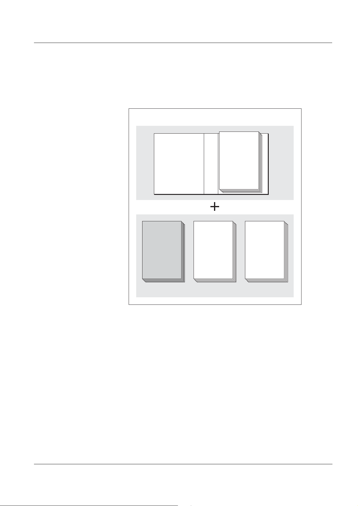
Fig. 1-1 Structure of the IQ SENSOR NET operating manual
The IQ SENSOR NET operating manual has a modular structure like the
IQ SENSOR NET itself. It consists of a system operati ng manual and the
operating manuals of all the components used.
Please file this component operating manual in the ring binder of the
system operating manual.
1 - 1
Page 6
Overview NitraLyt
123 4 5
®Plus
700 IQ
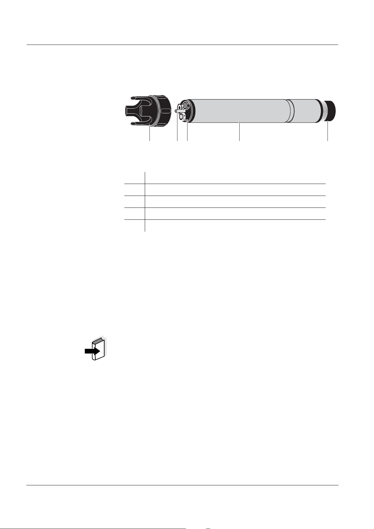
1.2 Structure of the nitrate sensor NitraLyt
Fig. 1-2 Structure of the nitrate sensor NitraLyt
1 Protective hood
2 Temperature probe
3 Electrode support with electrodes
4 Sensor shaft
5 Plug head connector
Electrodes An NitraLyt
electrode and an ion sensitive electrode for the main parameter,
ammonium. The electrodes are screwed into the electrode support .
The electrode support has two receptacles for this.
®Plus
700 IQ
®Plus
700 IQ
®Plus
700 IQ sensor ready to measure requires a reference
Automatic chloride
compensation
With the aid of the automatic chloride compensation, the influence of
chloride ions on nitrate measurement due to measurin g techni que is
compensated for during measurement. To determine the chloride
concentration, the NitraLyt
®Plus
700 IQ is equipped with a chloride
electrode.
Note
Information on the fundamentals of measuring with ion sensitive
electrodes are given in the
ONLINE ANALYSIS.
YSI primer, ION SELECTIVE MEASUREMENT IN
1 - 2
ba76004e01 01/2012
Page 7
NitraLyt
Ref
VARiON
®Plus
NO3
Blind plug
VARiON
®
Ref
®Plus
700 IQ Overview
Operating modes and
electrode equipment
Calibration free
operation
Due to its modular structure, the NitraLyt
®Plus
700 IQ can be adapted
to various requirements (see following table).
Notes:
The reference electrode has an extra receptacle marked by a recess.
The ion sensitive electrodes can be mounted in the remaining two
receptacles in any order. Empty receptacles have to be closed with the
VARiON
Nitrate measurement
The NitraLyt
®
BP blind plug.
Operating mode Electrode equipment
®Plus
700 IQ nitrate sensor is immediately ready to
measure after being equipped with electrodes. For precise
measurements, it is only necessary to adjust the electrodes to the
sample matrix ("matrix adjustment"). In the recommended application
(see
section 1.3 RECOMMENDED FIELDS OF APPLICATION), the measuring
characteristics of the electrodes remain stable for their entire service
life. Thus, calibration is no longer required.
Shielding of the
NitraLyt
®Plus
700 IQ
Possible changes of the sample matrix can be determined by
occasional comparison measurements (e.g. photometer) and
compensated for by a new matrix adjustment. The sensor does not
have to be taken out of the sample for this.
The NitraLyt
electrodes in conjunction with the
®Plus
700 IQ nitrate sensor and the corresponding
IQ SENSOR NET system form a
measuring system that is protected to a high degree against low and
high frequency interference as well as against the indirect effects of
lightning strikes.
ba76004e01 01/2012
1 - 3
Page 8

Overview NitraLyt
1.3 Recommended fields of application
®Plus
700 IQ
The NitraLyt
®Plus
700 IQ nitrate sensor is a sensor for the online
determination of nitrate ions in water or wastewater applications. It
supplements D. O. measurement in the aeration tank of waste water
treatment plants and enables an efficient process control of nitrogen
removal.
Note
More detailed information o n measuring with ion sensitive electrodes is
given in the
ANALYSIS.
YSI primer, ION SELECTIVE MEASUREMENT IN ONLINE
1 - 4
ba76004e01 01/2012
Page 9
NitraLyt
®Plus
700 IQ Safety instructions
2 Safety instructions
Special user
qualifications
General safety
instructions
This component operating manual contains special instructions that
must be followed in the operation of the NitraLyt
®Plus
700 IQ nitrate
sensor. Thus, it is essential to read this component operating manual
before carrying out any work using this sensor. In addition to this
manual, the S
AFETY chapter of the IQ SENSOR NET system operating
manual must be followed.
Always keep this component operating manual together with the
system operating manual and any other component operating manuals
in the vicinity of the IQ
The NitraLyt
®Plus
SENSOR NET system.
700 IQ nitrate sensor was developed for applications
in online measurement - essentially in the field o f wastewat er
treatment. Thus, we assume that the operators are familiar with the
necessary precautions to take whe n dealing with c hemicals as a resul t
of their professional training and experience.
Safety instructions in this operat ing manual are identified by the
warning symbol (triangle) in the left column. The signal word (e. g.
"Caution") indicates the level of danger:
Warning
indicates instructions that must be followed precisely in order to
prevent serious dangers to persons.
Other labels
Caution
indicates instructions that must be followed precisely in order to
avoid slight injuries or damage to the instrument or the
environment.
Note
indicates notes that draw your attention to special features.
Note
indicates cross-references to other documents, e.g. operating
manuals.
ba76004e01 01/2012
2 - 1
Page 10
Safety instructions NitraLyt
2.1 Authorized use
®Plus
700 IQ
Function and
operational safety
The authorized use of the Nitr aLyt
in consists of its use as a sensor within the IQ
®Plus
700 IQ with the electrodes bu ilt
SENSOR NET.
Please observe the technical specifications according to chapter 9
TECHNICAL DATA. Only operation according to the instructions given in
this operating manual is considered to be authorized.
Any other use is considered to be unauthorized. Unauthorized use
invalidates any claims with regard to the guar antee.
Caution
Only connect and operate the sensor together with IQ SENSOR NET
accessories.
2.2 General safety instructions
The sensor left the factory in a safe and secure techni cal condition.
The failure-free function and operational safety of the sensor is only
guaranteed if the generally applicabl e safety measures and the special
safety instructions in this oper ating manual ar e foll owed during i ts use.
The failure-free function and operational safety of the sensor is only
guaranteed under the environmental conditions that a re speci fied in
chapter 9 TECHNICAL DATA.
The specified temperature (chapter 9 TECHNICAL DATA) must be
maintained during the operation and transport of the sensor. Protect
the sensor, particularly against frost or overheating.
Caution
The sensor may only be opened by specialist s authorized by YSI.
2 - 2
ba76004e01 01/2012
Page 11

NitraLyt
®Plus
700 IQ Safety instructions
Safe operation If safe operation i s no longer possi ble, the sensor must be taken o ut of
operation and secured against inadvertent operation.
Safe operation is no longer possible if the sensor :
has been damaged in transport
has been stored under adverse conditions for a lengthy period of
time
is visibly damaged
no longer operates as described in this manual.
If you are in any doubt, contact the supplier of your sensor.
Obligations of the
operator
The operator of the sensor must ensure that the following rules and
regulations are followed when dealing with hazardous substances:
EEC directives for protective labor l egislation
National protective labor legislation
Safety regulations
Safety data sheets of the chemical manufacturer.
ba76004e01 01/2012
2 - 3
Page 12

Safety instructions NitraLyt
®Plus
700 IQ
2 - 4
ba76004e01 01/2012
Page 13
NitraLyt
®Plus
700 IQ Commissioning
3 Commissioning
3.1 Scopes of delivery
YSI supplies the NitraLyt
®Plus
700 IQ in sets for different measuring
requirements. Each set contains the following components:
Unequipped sensor NitraLyt
®Plus
700 IQ. The electrode recepta cles
are closed with blind plugs
Reference electrode, VARiON® Ref
Depending on the set, the suitable selection from the following
measurement and compensation electrodes:
®
– VARiON
– VARiON
Plus
NO3 (nitrate electrode)
®
Plus
Cl (chloride electrode for compensation)
Special socket wrench
VARiON® 700 IQ-SK protective hood
Potassium chloride solution for storing the reference electrode
Operating manual and YSI primer, ION SELECTIVE MEASUREMENT IN
ONLINE ANALYSIS.
Note
Information on the avai lable s ets is given in the YSI catalog and on the
Internet.
ba76004e01 01/2012
3 - 1
Page 14

Commissioning NitraLyt
3.2 IQ SENSOR NET system requirements
®Plus
700 IQ
Software statuses of the
controller and terminal
components
Operation of the NitraLyt
statuses in the IQ
SENSOR NET, depending on the system:
®Plus
700 IQ requires the following software
DIQ/S 182 Software: Version 3.21 or higher
MIQ/MC Controller software: Version 2.83 or higher
IQ software pack Software version: 5.00 or higher
3 - 2
ba76004e01 01/2012
Page 15
NitraLyt
Watering cap
Junction
Reference electrode
Nut
Sealing ring
®Plus
700 IQ Commissioning
3.3 Notes on the handling of the electrodes
Commissioning
The electrodes of the NitraLyt
®Plus
700 IQ nitrate sensor were
developed for the rough use in waste water treatment plants. They are,
however, precision parts that can be damaged by inappropri a te use.
Therefore, exactly follow the instructions in the two following chapters.
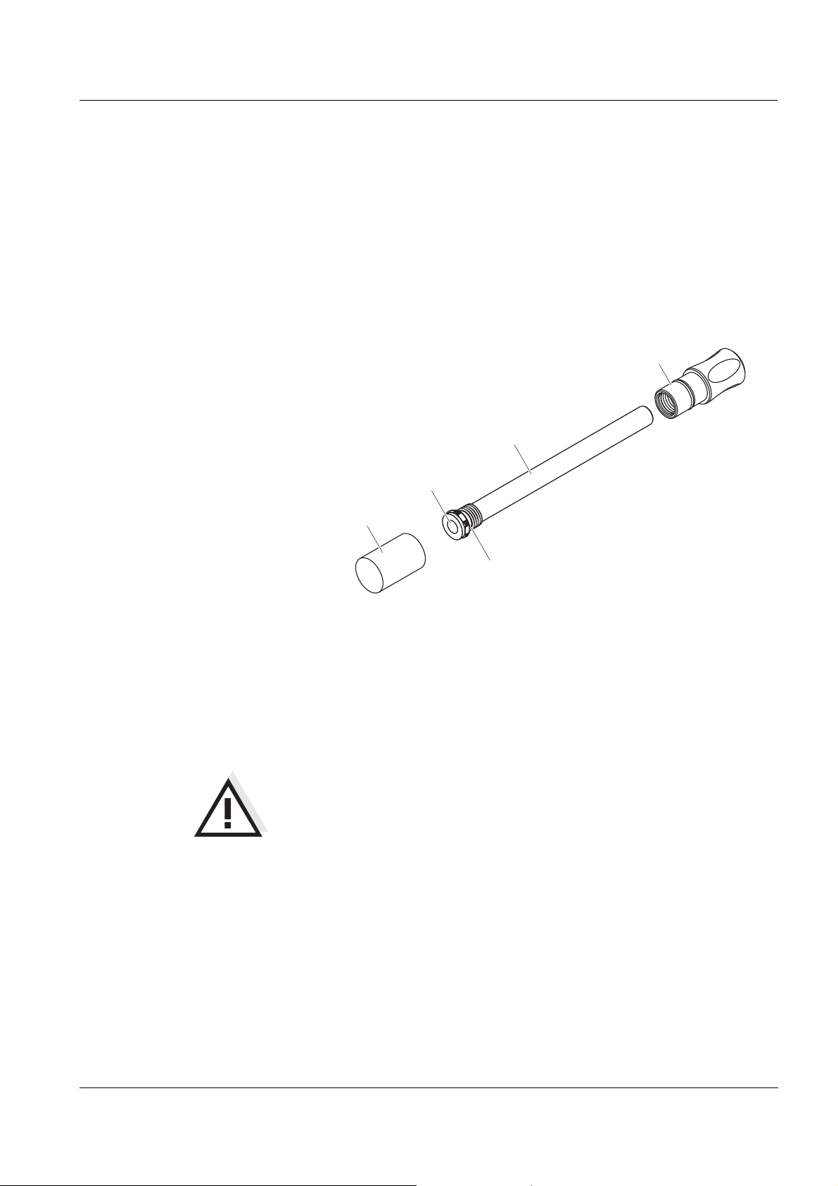
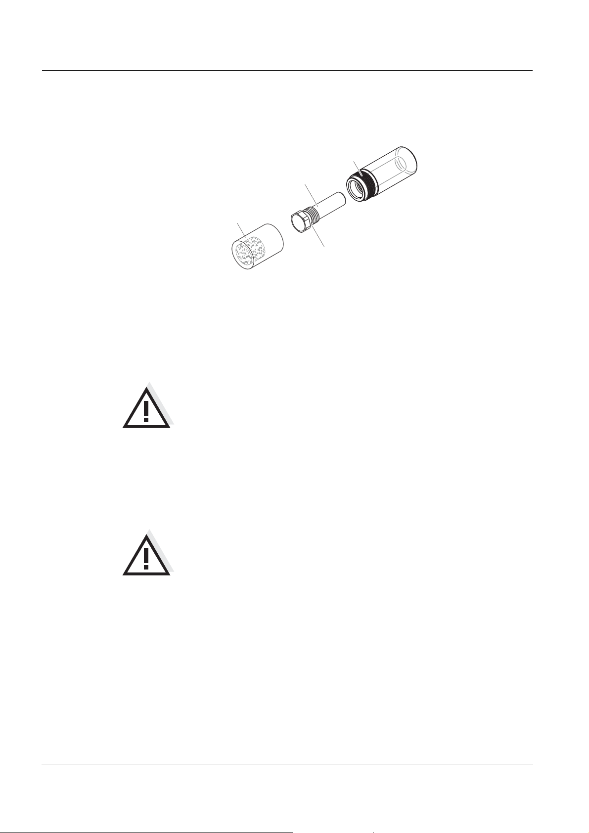
3.3.1 Reference electrode
Fig. 3-1 Reference electrode with storing aids
In the delivery condition, the electrode is equipped with a watering cap
and a nut that protects the screw-in thread. The watering cap cont ains
3
mol/l potassium chloride solution. Before mounting, unscrew the
watering cap. Then, using the special hexagon key, unscrew the
electrode from the nut. Keep both storing aids in case you want to store
the electrode.
Caution
The junction of the reference electrode must not
dry up (follow notes on storage)
be damaged
be brought into contact with grease.
Notes on storage If you will not use the electrode for a longer period of time, screw the
electrode into the nut as far as it will go. Fill the wateri ng cap to the brim
with 3
mol/l potassium chloride s olution and tightly scr ew the watering
cap on the electrode by hand.
ba76004e01 01/2012
3 - 3
Page 16
Commissioning NitraLyt
Watering cap
Electrode
Nut
Sealing ring
3.3.2 Measurement electrodes and compensation electrodes
Commissioning
Fig. 3-2 Measurement electrode or compensation electrode with storing aids
In the delivery condition, each electrode is equipped with a watering
cap and a nut that protects the screw-in thread. Prior to installation, fi rst
remove the watering cap and, using the special hexagon key, unscr ew
the electrode from the nut. Keep both storing aids in case you want to
store the electrode.
®Plus
700 IQ
Caution
The membrane of the electrode must not
dry up (follow notes on storage)
be damaged
be brought into contact with grease.
Notes on storage If you will not use the electrode for a longer period of time, screw the
electrode into the nut as far as it will go. Soak the foam insert i n the
watering cap with VARiON
®
/ES-1 standard solution (lower
concentration) and plug the electrode into the watering cap.
Caution
Make sure to use the correct solution for the watering cap
(VARiON
solution of the reference electrode instead the function of the
electrode can be seriously damaged.
®
/ES -1 standard solution). If you use the watering
3 - 4
ba76004e01 01/2012
Page 17
NitraLyt
Measurement
electrode
Compensation electrode
or blind plug
Reference
electrode
Mark for
reference electrode
Special socket wrench
®Plus
700 IQ Commissioning
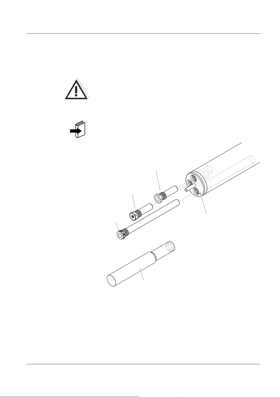
3.4 Preparing the sensor for measurement
3.4.1 Equipping the sensor with electrodes
Caution
The sensor can be damaged by dirt and moisture. Before
mounting the electrodes make sure the area behind the sealing
ring of the electrodes and the receptacle are dry and clean. The
NitraLyt
or original blind plugs are mounted.
Note
More detailed information on the electrode equipment for the various
operating modes is given in the table on
®Plus
700 IQ may only be submersed when the electrodes
page 1-3.
ba76004e01 01/2012
Fig. 3-3 Equipping the sensor with electrodes.
All receptacles are closed with blind plugs in the delivery condition.
Screw the electrodes into the receptacles instead of the blind plugs.
When doing so observe the following points:
The receptacle for th e reference el ectrode is marked by a r ecess. It
extends into the inside of the sensor clearly deeper than the other
two receptacles (see
Fig. 3-3).
3 - 5
Page 18
Commissioning NitraLyt
The measurement and compensation electrode can be mounted in
the remaining two receptacles in any order.
During installation make sure th e area behind the sealing ring of t he
electrode and the receptacle are absolutely dry and clean.
Plug the electrode on the special socket wrench provided and insert
the electrode with the special socket wrench.
Screw until the electrode seats without any gap on the electrode
support. Thus the tightness and electric al contacting are granted.
Note
When mounted, the electrodes can be recognized by the features
described in
section 6.3.
3.4.2 Mounting the protective hood
®Plus
700 IQ
CH cleaning head
(option)
For permanent operation, we recommend to use the CH cleaning head
for compressed air-driven cleaning. It is mounted instead of the
standard protective hood. Th e compressed air cleani ng is st arted ti mecontrolled via the IQ
components is given in the
SENSOR NET system. Information on the requir ed
YSI catalog and on the Internet.
If no CH cleaning head is used the standard protective hood should
always be mounted for measuri ng. It protects the electrodes from rough
mechanical impact.
3 - 6
ba76004e01 01/2012
Page 19
NitraLyt
1
®Plus
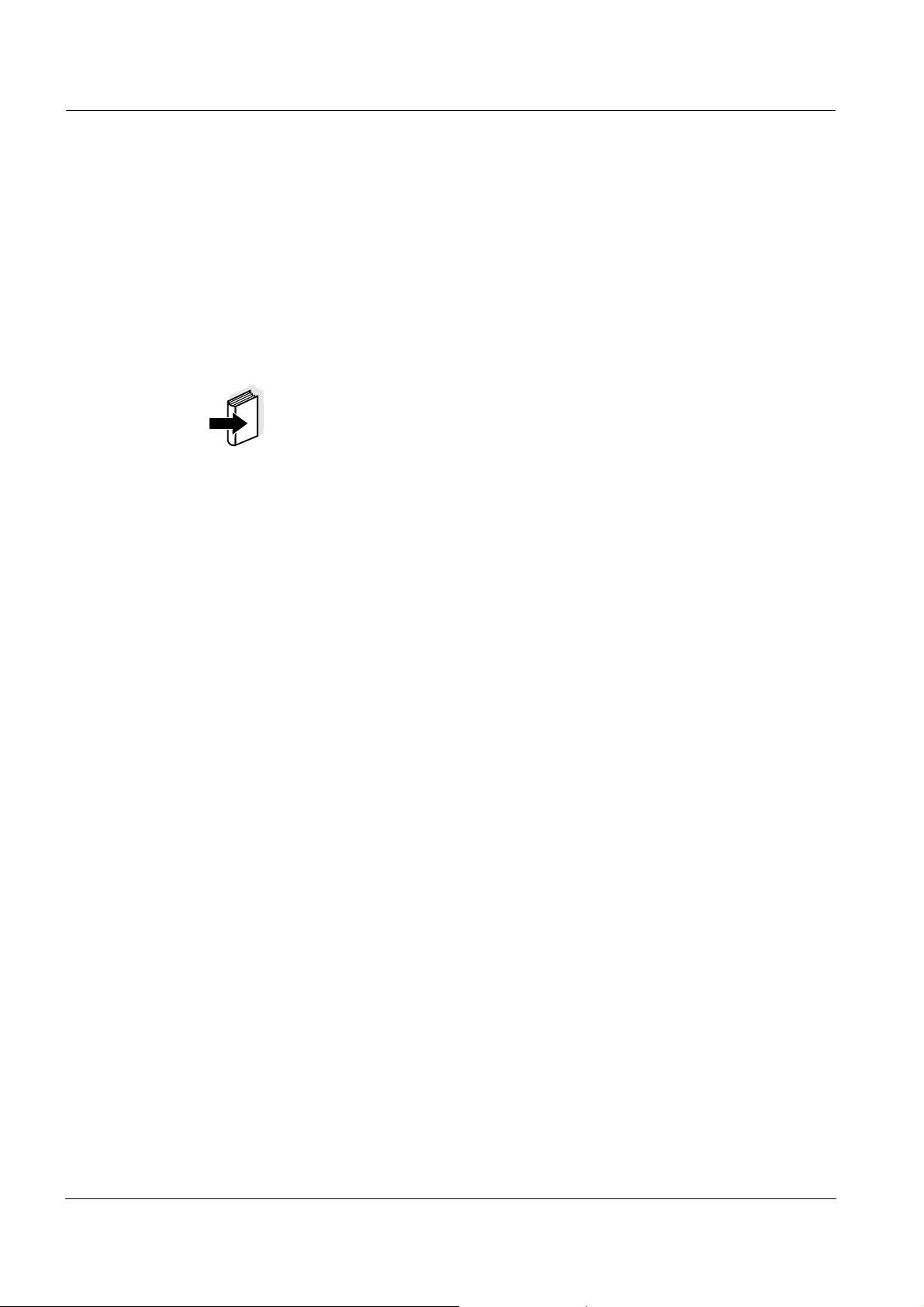
700 IQ Commissioning
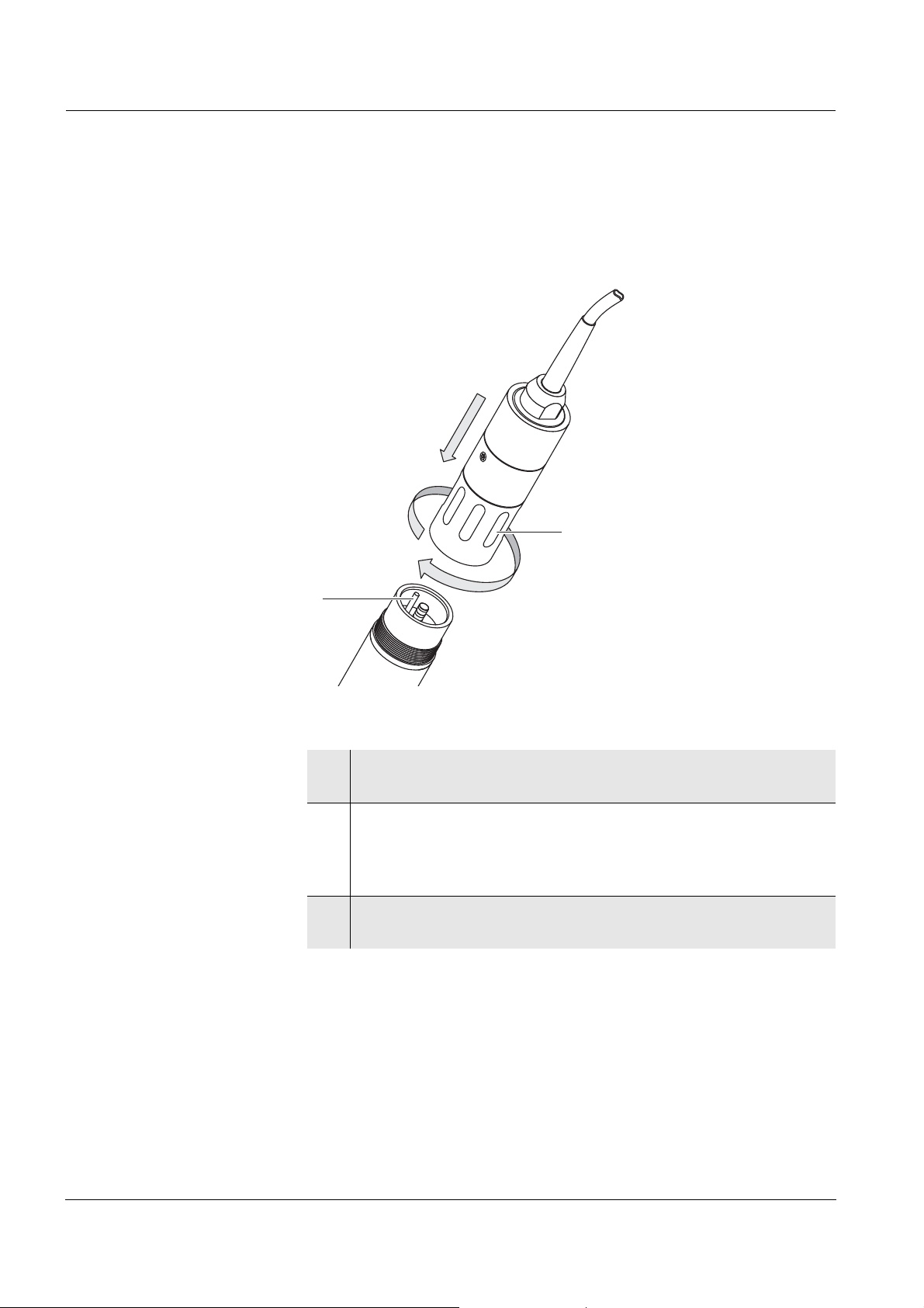
Mounting the standard
protective hood
Cleaning the protective
hood
Connection cable The SACIQ sensor connection cabl e is required to connect the sensor.
Fig. 3-4 Mounting the standard protective hood.
1 Loosen the coupling ring (1) of the protective hood.
2 Push the protective hood on the sensor as far as it will go.
3 Tighten the coupling ring of the protective hood.
The coupling ring of the protective hood can be ta ken apart for cleaning
purposes (see
section 6.2 EXTERIOR CLEANING).
3.4.3 Connecting the sensor to the IQ SENSOR NET
Information on this and other IQ
the
YSI catalog and on the Internet.
SENSOR NET accessories is given in
Note
Do not suspend the sensor on the sensor connection cable. Use an
armature or electrode ho lder. In formation on this and other IQ S
N
ET accessories is given in the YSI catalog and on the Interne t.
ENSOR
ba76004e01 01/2012
Note
How to connect the SACIQ sensor connection cable to the
IQ
SENSOR NET is described in chapter 3 INSTALLATION of the
IQ
SENSOR NET system operating ma nual.
3 - 7
Page 20
Commissioning NitraLyt
SACIQ
1
2
®Plus
700 IQ
Are the plug
connections dry?
Connecting the sensor
to the sensor
connection cable
Before connecting the sensor and sensor connection cable, mak e sure
that the plug connections are dry. If moisture gets into the plug
connections, first dry t he plug con nections (dab them dr y or blo w them
dry using compressed air).
Fig. 3-5 Connect the sensor
1 Take the protective caps of f the plug connections of the sensor
and the SACIQ sensor connection cable, and keep them safe.
2 Plug the socket of the SACIQ sensor connection cable onto the
plug head connector of the sensor. At th e same time, rotate the
socket so that the pin in the plug head connect or (1) clicks into
one of the two holes in the socket.
3 Then screw the coupling ring (2) of the sensor connection
cable onto the sensor up to the stop.
3 - 8
ba76004e01 01/2012
Page 21

NitraLyt
®Plus
700 IQ Commissioning
3.5 Settings
3.5.1 General information
Automatic electrode
recognition
The NitraLyt
electrodes and checks the equipment for validity. If the sensor is
®Plus
700 IQ software automaticall y recognizes the bui lt-in
correctly equipped it is displayed in the list of sensors with the
designation, "NitraLyt+".
Carrying out settings Switch to the main settings menu from the measured value display with
<S>
. Then navigate to the setting menu (setting table) of the sensor.
The exact procedure is described in the relevant IQ
SENSOR NET
system operating manual.
The setting tables for the NitraLyt+ are described in the following
chapter.
ba76004e01 01/2012
3 - 9
Page 22

Commissioning NitraLyt
3.5.2 NitraLyt+ setting table
Menu item Selection/values Explanations
®Plus
700 IQ
Measuring mode NO3-N
NO3
mV
Measuring range
(Measuring mode: NO3-N)
AutoRange
0.1 ... 100.0 mg/l
1 ... 1000 mg/l
Measuring range
(Measuring mode: NO3)
AutoRange
0.5 ... 450.0 mg/l
5 ... 4500 mg/l
Measuring range
-2000 ... 2000 mV Fixed range
(Measuring mode: mV)
Chloride compens. automatic / manual
1 ... 1000 mg/l
Citation form of the mass concentration or
voltage of the electrode.
2 measuring ranges can be selected.
With AutoRange, the instrument
automatically switches to the suitabl e
measuring range.
2 measuring ranges can be selected.
With AutoRange, the instrument
automatically switches to the suitabl e
measuring range.
automatic
(with a chloride electrode mounted):
When a chloride electrode is mounted, the
chloride compensation takes places
automatically only. The value of the
chloride concentration measured at the
time the setting table was opened is
displayed in the next line.
Calib. history Cl
(only with Chloride
compens. automatic)
Do not download
Transmit to log book
manual
(without any chloride electrode mounted):
After determining the chloride content of
the test solution enter the determined
chloride content manually in the next line.
TThe measured value is accordingly
corrected by the entered chloride content.
Note: Detailed information on the subject
of chloride compensation is given in the
YSIYSI primer, ION SELECTIVE
MEASUREMENT IN ONLINE ANALYSIS.
Send to log book generates a log book
message with the calibration history of the
chloride electrode. When opening the
setting table again the setting is reset to
Do not download.
3 - 10
ba76004e01 01/2012
Page 23

NitraLyt
®Plus
700 IQ Commissioning
Menu item Selection/values Explanations
IQ-LabLink not active (not used)
Temperature mode
°C
°F
Unit of the measured temperature value
(Celsius, Fahrenheit).
Temp. adjustment -1.5 °C ... +1.5 °C The temperature compensation function
enables the temperature sensor to be
balanced against a reference temperatur e
measurement (displacement of the zero
point by ±1.5 °C).
Notes:
Due to the thermal capacity of the
sensor, it is necessary to place it in a
container with at least 2 liters of water.
Leave the sensor in this container for at
least 15 minutes while stirring
occasionally, then carry out the
adjustment.
If the temperature difference of the
water and sensor is > 10°C, leave the
sensor in the container for at least one
hour while stirring occasionally.
Conc. offset -1.0 mg/l ... +1.0 mg/l Constant value, which is added to the
measuered value.
Program level 0 ... 2 Program extension (0 = Off = standar d set-
ting).
Refer to section 4.2.4 for det ails about the
program extension.
Save and quit The system confirms the saving of the
settings and the display switches to the
next higher level.
Quit The display switches to the next higher
level without saving the new settings.
ba76004e01 01/2012
3 - 11
Page 24

Commissioning NitraLyt
®Plus
700 IQ
3 - 12
ba76004e01 01/2012
Page 25

NitraLyt
Start: press
<C>
Electrode
zeroing
Yes/No
Selection of procedure
Matrix adjustment Check Calibration
Procedures for specia l cases
(see section 4.3)
Calibration free operation
Yes if a new or different elect rod e i s
commissioned
®Plus
700 IQ Matrix adjustment, check and calibration
4 Matrix adjustment, check and calibration
4.1 General information
Calibration free
operation
Steps
The NitraLyt
®Plus
700 IQ nitrate sensor is immediately ready to
measure after being equipped with electrodes. For precise
measurements, it is only necessary to adjust the electrodes to the
sample matrix ("matrix adjustment"). In the recommended application
(see
section 1.3 RECOMMENDED FIELDS OF APPLICATION), the measuring
characteristics of the electrodes remain stable for their entire service
life. Thus, calibration is no longer required.
Possible changes of the sample matrix can be determined by
occasional comparison measurements (e.g. photometer) and
compensated for by a new matrix adjustment. The sensor does not
have to be taken out of the sa mple for this. At the same time, a matrix
adjustment provides information on the state of the electrodes.
ba76004e01 01/2012
Fig. 4-1 Schematic diagram
4 - 1
Page 26

Matrix adjustment, check and calibration NitraLyt
Drift potential Simultaneously with the matrix adjustment (or calibration), the drift
voltage DV(mV) of the combination electrode is determined. It serves
to evaluate the long-term behavior of the combination electrode. The
drift voltage changes due to the following factors:
Influences due to the sample composition (matrix)
Change of the characteristics of the combination electrode.
Electrode zeroing The temporal change of the drift voltage is recorded in the calibration
history so that the long-term behavior of a combination electrode can
be evaluated. As a start value, the user has to set the drift voltage to
zero at the beginning of this evaluation period in order to observe
changes in the calibration history.
The electrode zeroing itself i s carried out with the matrix adjustment (or
calibration) procedure for the selected combination electrode(s). It
becomes effective if the procedure was successfully carried out.
The electrode zeroing can be carried out by the user for each electrode
(nitrate and chloride combinati on electrode) separately and at any t ime.
We recommend, however, to start the evaluation period wi th the
commissioning of a new or different electrode to be able to see the
entire operation period of an electrode in the calibration history.
®Plus
700 IQ
Resetting the slope by
electrode zeroing
Maintenance and
calibration case,
VARiON
®
Case
It is not possible to zero a n electrode with the Check pr ocedure, as this
procedure stores no data in the sensor.
Electrode zeroing with the matrix adjust m ent procedure resets the
slope to the default sett ing (+ or - 59.2
mV) at the same time. Electrode
zeroing with the calibrati on procedure replaces the existing slope with
the newly determined value.
For adjustment, calibration and maintenance activities on site, the
VARiON
required accessories (details, see
®
Case is available. The convenient case provides room for all
section 6.1).
4 - 2
ba76004e01 01/2012
Page 27

NitraLyt
®Plus
700 IQ Matrix adjustment, check and calibration
4.2 Matrix adjustment
4.2.1 General information on matrix adjustment
This procedure adjusts the value measured directly in the test sample
to an independently determined reference value ("lab value"). To
determine the reference value s, a sampl e is taken from the measur ing
solution and the relevant concentrations are measured (e.g.
photometrically).
First select for which of the installed combinat ion electrodes the matrix
adjustment should be carried out. Based on this selection and the
electrode equipment, the sensor so ftware deter mines the ion t ypes for
which a reference measurement must be car ried out. The menu guided
routine adapts itself correspondingly and informs you of all necessary
actions.
4.2.2 Carrying out the matrix adjustment Note
A chloride electrode should be checked for coatings and pol ished off as
Main steps
necessary before the matrix adjustment is carri ed out (see
Step 1: Determination of all combination elect rode vol tages
section 6.4).
("reference voltages"). The sensor is in the sample.
The procedure is started from the measured value display
with c. After completion the system returns to the
measured value display.
Step 2: Sampling at the same place and time if possible and
determination of all relevant refer ence values
Step 3: Entry of the measured reference values. This step is
started by pressing c again.
Online help A comfortable, menu guided routine guides you through the matrix
adjustment. All steps are easily and understandabl y explained on the
display. In addition, you can c all up an Online help for each step. To do
so, use the arrow keys <>
highlighting to the Online hel p menu item and press <OK>
or toggle swit ch <> to move the
. A help text
with detailed information on t he relevant operati ng step appears on th e
display. It provides, for exampl e, important instruct ions on how to keep
the correct basic conditions. When <OK>
is pressed once again, the
display returns to the current operating step.
Matrix adjustment with
electrode zeroing
ba76004e01 01/2012
After installing a new or different electrode you have to zero the
electrode to facilitate a long-ter m evaluation. Details on electrode
zeroing, see
section 4.1.
4 - 3
Page 28

Matrix adjustment, check and calibration NitraLyt
®Plus
Practical instructions The nitrate concentration has to be determined immediately after
taking the sample as the nitrate content changes ver y quickly due to
the micro organisms that are present. It is best to take the sample
using a syringe filter for transport to the laboratory or to stabilize it
otherwise. When adding stabilizi ng solutions, the diluti on factor has
to be taken into account.
While determining the reference concentra tions in the lab (step 2),
you can use the sensor for control purpose s agai n by switchi ng the
maintenance condition off and thus releasing the linked outputs . The
sensor continues to use the data of the previous matrix adju stment
(or calibration). The ref erence volt ages determined i n step 1 will
be lost. They remain stored until step
3 of the matrix adjustment is
completed. They do not have to be noted and entered again.
Use the Online help if you are unsure of anything during the matrix
adjustment.
700 IQ
not
4 - 4
ba76004e01 01/2012
Page 29

NitraLyt
Last electrode
zeroing via
matrix adjustment
Chronological list of
the last matrix
adjustments
®Plus
700 IQ Matrix adjustment, check and calibration
4.2.3 Result of the matrix adjustment
Evaluation After the matrix ad justment, the system automatically evaluates the
current condition of the electrode(s) based on the drift voltage. For a
successful matrix adjustment, the drift voltage must be within the range
-45
mV to +45 mV. The drift voltage is set to 0 mV if you have selected
to zero the electrode.
At the end of the matrix adjustment procedure the drift voltage of all
selected electrodes is shown on the display. The evaluation is
displayed with "+" (successful) or "-" (unsuccessful). Additionally, the
slopes are displayed that are used for the current measured value
calculation. The slopes are marked by a star (*) as they were not
changed by the matrix adjustment.
Taking over the
determined values
History of matrix
adjustments
(available in the
IQ
SENSOR NET system
2020
XT)
For each successfully adjusted electrode you can individually decide
whether the values should be stored for measurement.
Note
If the matrix adjustment was erroneous due to an incorrect
determination or entry of the reference concentration, you can correct
the entry (if necessary several times). If, by do ing so, it is not possi ble
to eliminate the error, the complete matrix adjustment has to be
repeated or discarded for this elect rode. If it is discarded, measurement
is continued with the values of the last valid matrix adjustment (or
calibration). Values of successfull y adjusted electrodes that were
already stored are retained.
Note
Actions for error e limination are given in t he Online help and in chapter
8 WHAT TO DO IF ....
The history of matrix adjustments can be viewed in the so-called
calibration history.
ba76004e01 01/2012
Fig. 4-2 Calibration history of NitraLyt+ with matrix adjustments
4 - 5
Page 30

Matrix adjustment, check and calibration NitraLyt
The history of matrix adjustments contains the foll owing information:
Date Date of the matrix adjustment
S Slope [mV] of the electrode.
The slopes are marked by a star (* ) because they were not changed
by the matrix adjustment or reset to the default condition with the
electrode zeroing.
DV Drift voltage [mV]
0 is displayed after an electrode zeroing.
Ref1 Reference concentration [mg/l]
Ref2 This column is of no importance for the matrix adjustment
Cl- Measured or entered chloride concentration [mg/l]
P Procedure (1 = matrix adjustment)
®Plus
700 IQ
T Temperature [°C]
R Evaluation of the matrix adjustment
+ : Matrix adjustment successful.
The sensor measures with the new adjustment data.
? : Matrix adjustment unsuccessful.
Invalid adjustment data was discarded. Measurement is
continued with the last valid values.
Note
The history of matrix adjustments of the chloride electrode i s not output
with the calibration history of the sensor (NitraLyt+). If necessary, you
can create a log book message with the calibration hist ory by means of
the menu item, Calib. history Cl in the setting table. How to do this is
described on
page 3-10. The log book message is given in the log book
(message code IC5396).
4 - 6
ba76004e01 01/2012
Page 31

NitraLyt
®Plus
700 IQ Matrix adjustment, check and calibration
4.2.4 Program extension
The simple matrix adjustment, as described in the sections 4.2.2 to
4.2.3, will in most cases lead to precise measurement result s. In some
cases, special effects in the matrix can cause the real characteristic
curve of the ISE measurement to deviate very much from the factory
characteristic curve. This can lead to measured val ues that are not
precise enough.
From sensor software version 3.20, the setting table provides the
Program Level setting, which can b e used to enhance the fu nctional ity
of the matrix adjustment. Program Level 0 is the simple matrix
adjustment as described in the sections
4.2.2 to 4.2.3. The program
levels 1 and 2 provide tools with which the real characteristic curve of
the ISE measurement can be better approximated.
For more detailed information please address your YSI contact person.
Note
To restore the factory characteristic curve, select Program Level 0 in
the setting table and then quit the menu with Save and quit.
ba76004e01 01/2012
4 - 7
Page 32

Matrix adjustment, check and calibration NitraLyt
4.3 Check and calibration in standard solutions
4.3.1 General information on checking and calibr ating
In addition to the comparison meas urement or matrix adjustment under
real measurement conditions, it is pos sible to check the function of the
entire sensor in standard solutions. If nece ssary, you can also take
over in the sensor the slope and potential level of the individual
combination electrodes via an exact calibration in standard solutions.
The slope will be retai ned with a future matr ix adj ustment if it i s carr ied
out without zeroing the electrode.
®Plus
700 IQ
When does a check or
calibration make sense?
Caution
The long term stable VARiON
in the recommended application. A check in standard solutions is
only of significance if all basic conditions (cleanness,
conditioning etc.) are strictly kept. Calib ration can cause major
measurement errors if the basic conditions are not sufficiently
kept. After calibrating, a matrix adjustment is normally required
additionally (always with the recommended application).
Standard solutions do not correspond to any real test sample!
A check or calibration can be useful in the following special cases:
If the measured values do not appear to be correct even after a
careful matrix adjustment and if you suspec t the electr ode slopes to
have changed
If a new application is to be started, the sample compositi on of which
considerably deviates from that of the recommended application
(see
section 1.3 RECOMMENDED FIELDS OF APPLICATION)
Routinely within the framework of the company quality assuranc e.
®Plus
electrodes are calibration-free
4 - 8
ba76004e01 01/2012
Page 33

NitraLyt
®Plus
700 IQ Matrix adjustment, check and calibration
Differences between
check and calibrati on
The check and calibration are c arried out in two separate routines . The
schema is the same with both routines: Two standard soluti ons with
different concentrations are measured one after the other. The
differences between the check and calibration are as follows:
For the check, the basic conditions to be kept are less str ict. It is
suitable as a quick method to check whether t he slope and potenti al
level of the combination electrodes are wi thin the allowed limits. The
results are just for in formation. No characterist ics or sensor settings
are changed.
For calibration, the basic condi tions must comply with very high
requirements (longer conditioni ng ti mes , discarding of the
conditioning solution, temperature adjustment etc.).
Correspondingly, it requires more time. During calibration, the slope
and drift voltage are exactly determined and evaluat ed. If the
calibration was successful, the determined values can be taken over
for measurement. The procedure can, howeve r, be used as a mere
check method. Calibration is documented in the calibration history
and in the log book.
Standard solutions For the check or calibrati on, the following two YSI standard solutions
are required in this order:
VARiON®/ES-2 (high concentration)
Online help A comfortable, menu guided routine guides you through the procedure .
Calibration with
electrode zeroing
VARiON®/ES-1 (low concentration).
These standard solutions contain all ion types that come into questi on
(nitrate and chloride) and are especially adapted to the
NitraLyt
®Plus
700 IQ.
All steps are easily and understandably explained on the di splay. In
addition, you can call up an Online help for each step. To do so, use
the arrow keys <> or toggle switch <> to move the
highlighting to the Online help menu and press <OK>. A help text wi th
detailed information on the relevant operating step appears on the
display. It provides, for exampl e, important instruct ions on how to keep
the correct basic conditions. When <OK>
is pressed once again, the
display returns to the current operating step.
After installing a new or different electrode you have to zero the
electrode to facilitate a long-ter m evaluation. Details on electrode
zeroing, see
section 4.1.
Note
A chloride electrode should be checked for coatings and pol ished off as
necessary before the check or calibration i s carried out (see
section
6.4).
ba76004e01 01/2012
4 - 9
Page 34

Matrix adjustment, check and calibration NitraLyt
®Plus
700 IQ
Preparations and
instructions on how to
keep the basic
conditions
Select a place where clean working conditions and a constant,
sufficiently high temperature are granted (a room, e.g. laboratory).
Temperatures under 10
°C extend the conditioning time
considerably.
Make sure the temperature of all components (sensor, standard
solutions, containers, accessories etc.) is similar and constant. We
recommend to store the standard sol utions in the same pla ce where
the check or calibration is carried out.
Use containers and accessories (beaker, stirring rod) that are
absolutely clean and without detergent residues. Detergent residues
can seriously affect the function of the electrodes.
Remove the protective hood and clean the sensor thoroughly.
Before the check, rinse the sensor wi th standard solution VARiON
ES-2.
Make sure the depth of immersion is sufficie nt (minimum 5 cm).
Make sure there are no air bubbles in front of the electrode
membrane.
Conditioning times: During the conditioning steps, all relevant
combination electrode voltages are indicated on the display. Thus
you can observe the conditioning process.
®
/
Regular stirring accelerates t he conditioning process considerably.
Stirring with a stirring rod or the sensor itsel f is sufficient.
For calibration, the standar d solution is discarded after conditioning.
This is pointed out by a corresponding note in the calibration routine.
It is essential for an exact calibrat ion result.
Use the Online help if you are unsure of anyt hing dur ing calibrati on.
4.3.2 Result of the check
Evaluation At the end of the check, the result for the combination electrodes is
shown on the display with "+" (successful) or "-" (unsuccessful). The
exact check criteria are given in the Online hel p of the result di splay. At
the same time the result is entered in the log book as an info messa ge.
There is
no entry in the calibration history.
4 - 10
ba76004e01 01/2012
Page 35

NitraLyt
®Plus
700 IQ Matrix adjustment, check and calibration
4.3.3 Result of the calibration
Evaluation With calibrati on, the system automati cally eval uates the condi tion of a
combination electrode based on the data of its characteristic curve. The
drift potential and slope are evaluated separately. For a calibration
procedure to be valid, the potential level, slope and drift voltage must
be within certain ranges.
Valid ranges for slope and drift potentia l:
Value of the slope: 50 ... 70 mV
Drift voltage: -45 ... +45 mV
The valid potential levels (MIN, MAX) can be t aken from the online help.
Taking over the
determined values
For each successfully calibrated electr ode you can indiv idu ally deci de
whether the values should be stored for measurement.
Note
Actions for error elimination are given in chapter 8 WHAT TO DO IF ....
ba76004e01 01/2012
4 - 11
Page 36

Matrix adjustment, check and calibration NitraLyt
Last electrode
zeroing (here, via
calibration)
Chronological list
with the last matrix
adjustments and
calibrations
®Plus
700 IQ
Calibration history
(available in the
IQ
SENSOR NET systems
2020
XT and
2020
XT USB only)
Date Date of the calibration or matrix adjustment
S Slope [mV] of the electrode.
In the calibration history, a calibration has the entries ES1 and ES2 in
the Ref1 and Ref2 columns which the matrix adjustment has not:
Fig. 4-3 Calibration history of NitraLyt+
The calibration history contains the following information:
Note: After a matrix adjustment, the values for the slope are marked
by a star (*) because they were not changed by this procedure.
DV Drift voltage [mV]
After an electrode zeroing and subsequent calibr ation or matrix
adjustment, 0 is displayed.
Ref1/Ref2 Depending on the procedure.
Matrix adjustment: Reference concentrat ion [mg/l]
Calibration: Used standard solution
Cl- Depending on the procedure.
Matrix adjustment: Chloride concentration [mg/l]
Calibration: Standard solution VARiON®/ES-2
P Procedure (1 = matrix adjustment, 3 = calibration)
T Temperature [°C]
R Evaluation of the calibration or matrix adjustment
+ : Calibration or matrix adjustment.
The sensor measures with the new calibration or adjustment
data.
? : Calibration or matrix adjustment unsuccessful.
Invalid calibration or adjustment data were discarded.
Measurement is continued with the last valid values.
4 - 12
ba76004e01 01/2012
Page 37

NitraLyt
®Plus
700 IQ Matrix adjustment, check and calibration
Note
The calibration history of the chloride el ectrode is not output with the
calibration history of the sensor (NitraLyt+). If necessary, you can
generate a log book message with the calibration history vi a the menu
item, Calib. history Cl in the setting table. How to do this is described
on
page 3-10. The log book message is given in the l og book (message
code IC5396).
ba76004e01 01/2012
4 - 13
Page 38

Matrix adjustment, check and calibration NitraLyt
®Plus
700 IQ
4 - 14
ba76004e01 01/2012
Page 39

NitraLyt
®Plus
700 IQ Measuring
5 Measuring
5.1 Measuring operation
Note the data given in section 9.2 APPLICATION CONDITIONS, especially
the minimum immersion depth of the sensor (> 50 mm with mounted
protective hood).
Note
To keep the sensor clean, we r ecommend to use the CH cleaning head
(see
chapter 7 REPLACEMENT PARTS AND ACCESSORIES).
5.2 Factors affecting the measured value Caution
Greases, oils, certain tensides and similar substances can
shorten the operational lifeti me of the el ectrodes. Ther efore, they
should not be present in the test sample.
Interfering ions Nitrate measurement with the NitraLyt
by the presence of chloride ions.
Note
The effects of influencing variables on measurement and
compensating actions are described in detail in the
SELECTIVE MEASUREMENT IN ONLINE ANALYSIS.
®Plus
700 IQ can be influenced
YSI primer, ION
ba76004e01 01/2012
5 - 1
Page 40

Measuring NitraLyt
®Plus
700 IQ
5 - 2
ba76004e01 01/2012
Page 41

NitraLyt
®Plus
700 IQ Maintenance and electrode exchange
6 Maintenance and electrode exchange
6.1 General maintenance notes Warning
Contact with the sample can be dangerous for the user!
Depending on the type of sample, suitable protective measures
must be taken (protective clothing, protective goggles, etc.) .
Maintenance condition We recommend to switch on the maintenance co ndit ion each t ime the
sensor is taken out of the measuring position. This avoids unwanted
reactions of linked outputs. More inform ation on the maintenance
condition is given in the relevant IQ
manual.
VARiON®/Epack The VARiON®/Epack set with usual replacement parts is avail able for
maintenance (see
chapter 7 REPLACEMENT PARTS AND ACCESSORIES).
SENSOR NET system operating
Maintenance and
calibration case,
VARiON
®
Case
For adjustment, calibration and maintenance acti vities on site, the
VARiON
®
Case is available. The conv enient case provides room for all
required accessories (details, see next page).
ba76004e01 01/2012
6 - 1
Page 42

Maintenance and electrode exchange NitraLyt
9
6
7
10
8
11
2
3
4
5
1
®Plus
700 IQ
Fig. 6-1 Sample equipment of the VAR iON® Case calibration and m aintenance c ase
1 Blind plug
2 Special socket wrench
3 Polishing strip
4 Replacement electrodes with watering caps
5 Compartments for various accessori es (wiping cloths, sample
6 Recess for sensor
7 Storing solution for reference electrode
bottles, personal protective equipment etc.)
8 Replacement reference electrode with storing aids
9 Calibration standards
10 Operating manual
11 Protective hood
6 - 2
ba76004e01 01/2012
Page 43

NitraLyt
®Plus
700 IQ Maintenance and electrode exchange
6.2 Exterior cleaning
Note
To keep the electrodes clean, we recommend to use the CH cleaning
head (see
chapter 7 REPLACEMENT PARTS AND ACCESSORIES).
With normal operation (e.g. municipal wast ewater) we strongly
recommend to clean the outside of the sensor and calibrate:
when it is strongly contaminated (after visual check)
if erroneous measured values are suspected
each time before removing or exchanging an electrode
Caution
Do not use any detergents for cleaning. Detergent residues can
seriously affect the function of the electrodes.
Note
We recommend to clean the sensor shaft and electrodes while the
sensor is still connected to the sensor connection cable. Otherwise,
moisture and/or dirt can get i nto the plug connection where it can cause
contact problems.
If you would like to disconnect the sensor from the sensor connection
cable, please note the following points:
Before disconnecting the sensor f rom the SACIQ sensor connection
cable, remove any larger pieces of contamination from the sensor,
particularly in t he area of the pl ug connection (brush it off in a bucket
of tap water, wash it off with a hose or wipe it off with a cloth).
Unscrew the sensor from the SACIQ sensor connection cable.
Always place a protective cap on the plug head o f the sensor and on
the SACIQ sensor connection cable so that no moisture or dirt can
get into the contacting surfaces.
In corrosive environments, close the socket of the sensor
connection cable with the screwable SACIQ-Plug when it is dry in
order to protect the elect rical contacts from corrosion. The protective
plug is available as an accessory (see
ACCESSORIES).
section 7.2 GENERAL
Cleaning the sensor Clean the sensor shaft with tap water and a soft sponge or brush.
Remove the protective hood. The electrodes are best cleaned under
running tap water using a soft toothbrush or brush.
ba76004e01 01/2012
6 - 3
Page 44

Maintenance and electrode exchange NitraLyt
1
2
3
®Plus
700 IQ
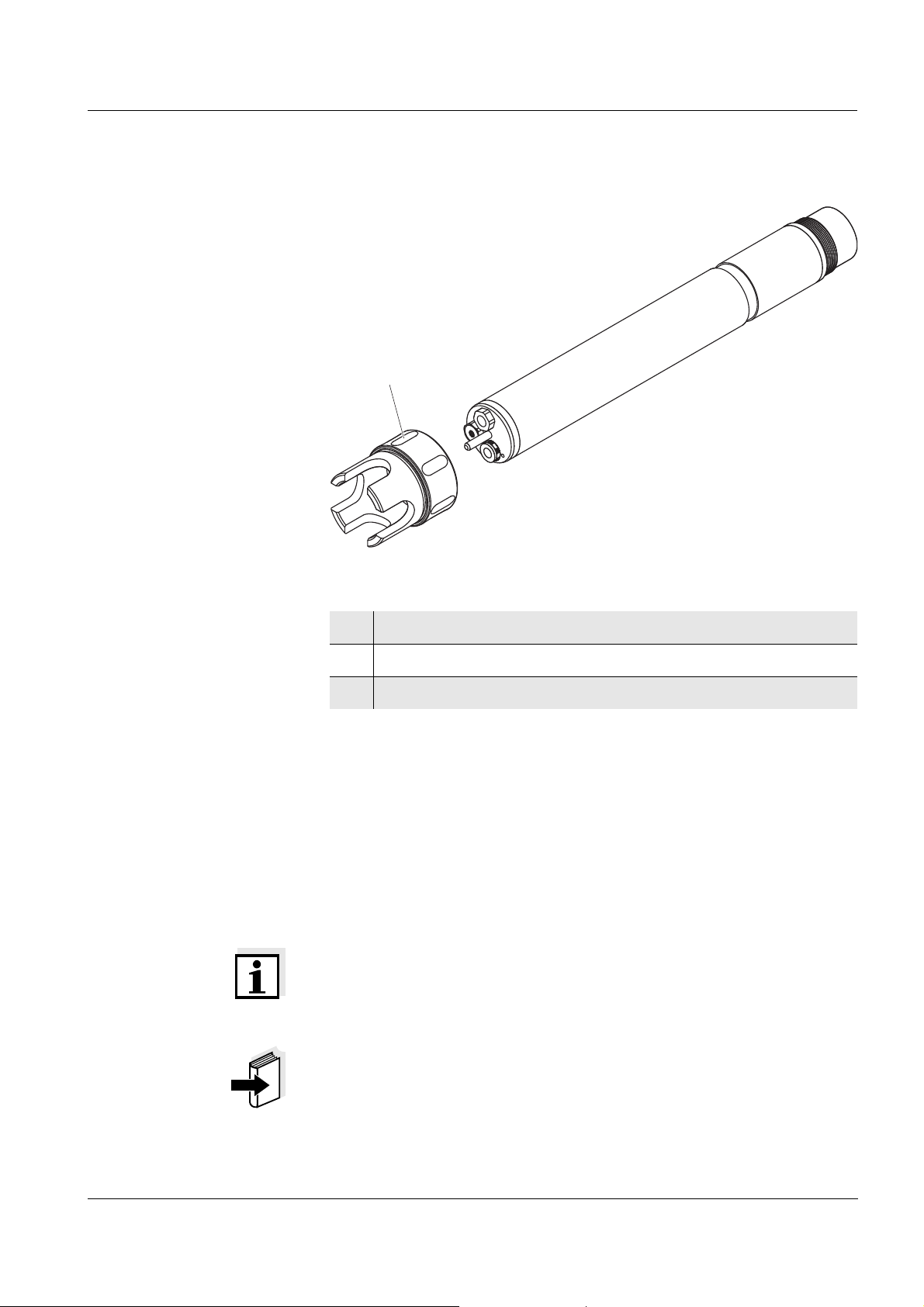
Cleaning the coupling
ring of the protective
hood
The coupling ring can be unscrewed and dismantled for cleaning as
follows:
Fig. 6-2 Dismantling the coupling ring
1 Remove the retaining ring (pos. 1 in Fig. 6-2).
2 Remove the intermediate ring (pos. 2) and sealing ring
(pos.
3).
After the parts have been cleaned, reassemble the coupling ring in
reverse order. When doing so make sure that the tapered side of the
intermediate ring (pos. 2) points towards the seali ng ring (pos. 3).
6 - 4
ba76004e01 01/2012
Page 45

NitraLyt
®Plus
700 IQ Maintenance and electrode exchange
6.3 Exchanging the electrodes Caution
The sensor can be damaged by dirt and moisture. Each time
before dismantling an electrode carefully clean the area around
the electrodes (
sure the area behind the sealing ring of the electrode and the
receptacle are dry and clean. The NitraLyt
submersed when the electrodes or original blind plugs are
mounted.
Use the special socket wrench provided to dismantle an electrode.
Electrodes are installed as described in
SENSOR WITH ELECTRODES.
section 6.2). Before mounting an electrode make
®Plus
700 IQ may only be
section 3.4.1 EQUIPPING THE
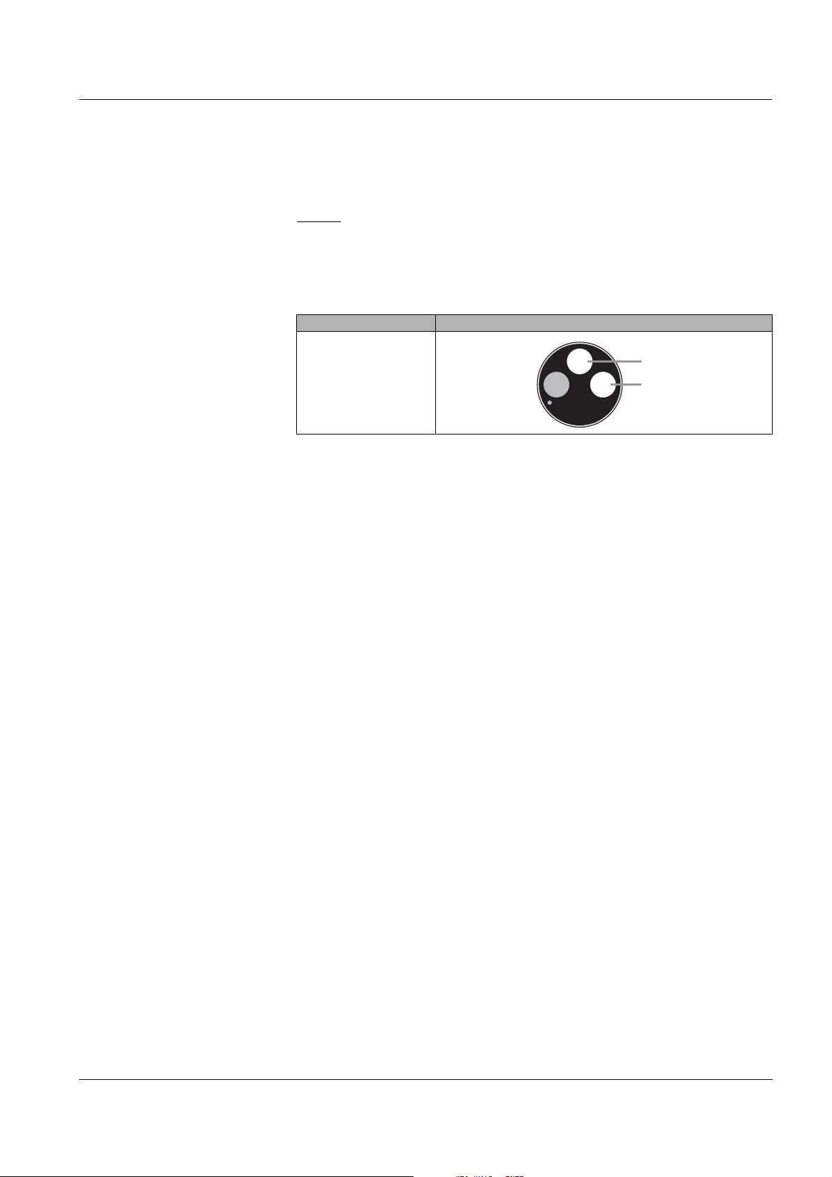
Recognizing the
electrode type from
outside
When mounted, the electrodes can be recognized by the following
features:
Electrode Hexagon Front
Other features
surface
VARiON® Ref black black – Thread at the
hexagon
VARiON
®Plus
NO3 white white – Labelling with
electrode type
VARiON
®Plus
Cl black black – Larger
membrane
– Membrane flush
with the front
surface
Note
For the correct storage of the electr odes pl ease fol low the i nstruct io ns
in
section 3.3 NOTES ON THE HANDLING OF THE ELECTRODES.
ba76004e01 01/2012
6 - 5
Page 46

Maintenance and electrode exchange NitraLyt
SF 300
6.4 Polishing the chloride electrode
Caused by the test medium, a coating can develop on the surface of
the chloride electrode, which reduces the electro de slope. To maintain
a proper chloride compensation the surface must be renewed by
polishing at regular intervals.
Caution
Danger of damaging the electrode. Exclusively use the SF 300
polishing strip. Never use commercial sandpaper or similar.
The polishing can be done while the electrod e is mounted (remove the
protective hood as necessary). To polish the electrode, use t he SF
polishing strip provided with the electrode. Moisten the rough side of
the polishing strip with water and polish off any coatings under slight
pressure.
®Plus
700 IQ
300
Fig. 6-3 Polishing the chloride electrode
6 - 6
ba76004e01 01/2012
Page 47

NitraLyt
®Plus
700 IQ Replacement parts and accessories
7 Replacement parts and accessories
7.1 Electrodes
Exchange electrodes
Storing equipment
Standard solutions
for calibration
Description Model Order no.
Reference electrode VARiON® Ref 107042Y
Nitrate electrode VARiON
Chloride electrode VARiON
®Plus
NO3 107045Y
®Plus
Cl 107047Y
Description Model Order no.
250 ml potassium chloride
KCl-250 109705Y
solution for the storage of the
electrode
7.2 General accessories
Description Model Order no.
1 liter combination standard 1
(low concentration)
VARiON®/ES-1 107050Y
Maintenance equipment
Protective plugs
1 liter combination standard 2
VARiON®/ES-2 107052Y
(high concentration)
Description Model Order no.
Polishing strip SF 300 203680Y
Description Model Order no.
Screwable plug for sensor
SACIQ-Plug 480065Y
connection cable
ba76004e01 01/2012
7 - 1
Page 48

Replacement parts and accessories NitraLyt
®Plus
700 IQ
General replacement
parts
Calibration and
maintenance case
Description Model Order no.
Protective hood VARiON® 700 IQ-SK 107056Y
Replacement parts set,
VARiON®/Epack 107057Y
comprising
– 1 blind plug for receptacle
– 1 special socket wrench
– 3 replacement sealing rings
for electrodes/blind plugs
– Storing equipment for
electrodes:
1 nut (transparent),
1 watering cap with sponge
1 nut (black)
1 watering cap (without
sponge) for reference
electrode
Description Model Order no.
Empty case for the storage of
VARiON® Case 107058Y
calibration and maintenance
equipment for the
NitraLyt
®Plus
700 IQ
7 - 2
Components for
cleaning system
Description Model Order no.
Cleaning head CH 900107Y
Passive valve module DIQ/CHV 472007Y
Active valve module (does not
MIQ/CHV PLUS 480018Y
require a free relay ou tput i n the
IQ
SENSOR NET system)
Air compressor for supply of the
sensor cleaning system with
compressed air
Cleaning Air Box
115 VAC
230 VAC
480017Y
480019Y
Note
Information on other IQ SENSOR NET accessories is given in the YSI
catalog and on the Internet.
ba76004e01 01/2012
Page 49

NitraLyt
®Plus
700 IQ What to do if ...
8 What to do if ...
8.1 Interpretation of the drift voltage
The drift voltage is influenced by the potential levels of the
measurement electrode and reference elec trode. If the pot ential levels
shift, e.g. caused by aging, both parts can move into the same direction
or into opposite directions. The comparison of the dri f t voltages of two
or three combination electrodes enables to dra w conc lusions
concerning the state of individual electrodes if a matrix adjustment or
calibration resulted in an invalid or considerably deviating drift voltage.
Assessment aids View the calibration history of the combination electrodes. In the
following cases, assessment is relati vely easy:
If the drift voltages of all combination electrodes show the same
trend, i. e. the drift voltages have shifted in the same direction
(positive or negative) by approximately the same amount, this
indicates that the potential level of the reference electrode has
shifted. The reference electrode is possibly highly contaminated or
at the end of its service life.
If the drift voltages of all combination electrodes do not show a trend
but shift by different amounts into different directions, the potential
level of the reference elec trode has not changed consider ably. Th e
invalid drift voltage is probabl y caused by a defective measuring
electrode. The measuring elec trode is possibly highly c ontaminated
or at the end of its service life.
ba76004e01 01/2012
8 - 1
Page 50

What to do if ... NitraLyt
8.2 Error causes and remedies
®Plus
700 IQ
No measured value
display
Cause Remedy
– Sensor not connected – Connect the sensor
– Incorrect electrode
– Correct electrode equipment
equipment
– Electrode(s) not at all or
incorrectly recognized by the
system
– Check the installation and
contacts of the electrode (gapfree mounting)
– Check electrode recept acle for
moisture
– If necessary, unscrew the
electrode/blind plug and
thoroughly dry the electrode/
blind plug and receptacle
– Unknown – Look for error messages in the
log book
– Liquid in the sensor shaft – Sensor defective, send it back
Measurement provides
implausible measured
values
Cause Remedy
– No matrix adjustment or
calibration carried out
– Adjustment or calibration
error (e.g. incorrect lab
values, contaminated
standard solutions)
– Manual chloride
compensation works with an
unsuitable value
– Electrode(s) not at all or
incorrectly recognized by the
system
– Adjust or calibrate the
electrode
– Check the adjustment or
calibration conditions
– Readjust or recalibrate the
electrode
– Determine and enter the
chloride concentration once
again, then recalibrate
– Check the installation and
contacts of the electrode (gapfree mounting)
– Check electrode recept acle for
moisture
– If necessary, unscrew the
electrode/blind plug and
thoroughly dry the electrode/
blind plug and receptacle
8 - 2
ba76004e01 01/2012
Page 51

NitraLyt
®Plus
700 IQ What to do if ...
Cause Remedy
– Electrode contaminated – Clean the electrode (see
section 6.2)
– Liquid in the sensor shaft – Sensor defective, send it back
Measurement provi des
jumping, unstable or
drifting values
Cause Remedy
– Measurement /
compensation electrode:
Electrode membrane not
moistened by measuring
solution, e.g. due to air in
front of the membrane
– Moisten membrane with
deionized water using a wash
bottle. To do so, position the
opening of the wash bottle on
the membrane and splash
against the membrane
vigorously
– Measurement /
compensation electrode:
Air bubble behind the
membrane
– Measurement electrode /
compensation and reference
electrode:
Insufficient electrical contact
in the electrode receptacle
– Hold the electrode in a vertical
position with the membrane
down and knock it on the side
with the special socket wrench
– Check the installation and
contacts of the electrode (gapfree mounting)
– Check electrode recepta cle for
moisture
– If necessary, unscrew the
electrode/blind plug and
thoroughly dry the electrode/
blind plug and receptacle
ba76004e01 01/2012
– Reference electrode dried up – Replace reference electrode
– Measurement /
– Replace defective electr ode
compensation electrode or
reference electrode leaky or
damaged
– Liquid in the sensor shaft – Sensor defective, send it back
8 - 3
Page 52

What to do if ... NitraLyt
®Plus
700 IQ
Faulty result of the
matrix adjustment
Faulty result of
calibration
Cause Remedy
– Error during procedure, e.g.
incorrect lab values
– Check the basic conditions
– Follow the practical notes on
page 4-4 or in the online help
– Recalibrate the electrode
– Electrode not sufficiently
adapted (conditioned) to test
sample
– Switch to mV mode and
observe measured value
– When measured value stable,
repeat matrix adjustment
– Reference electrode or
– Replace defective electrode
measurement electrode
defective due to aging (see
section 8.1)
Cause Remedy
– Error during procedure, e.g.
contaminated standard
solutions
– Check the basic conditions
– Follow the practical notes on
page 4-10 or in the online help
– Recalibrate the electrode
– Reference electrode or
measurement electrode
defective due to aging (see
section 8.1)
– Replace defective electrode
8 - 4
ba76004e01 01/2012
Page 53

NitraLyt
®Plus
700 IQ Technical data
9 Technical data
9.1 Measuring char acte r isti c s
Measuring principle Potentiometric measur ement by mea ns o f ion sensitive electrodes.
Modular structure with jointly used reference electrode and ion
sensitive electrodes. Integrated mic roprocessor electronics, screened
2-wire connection for power and data transmissi on.
Measured parameters
Measuring ranges and
resolution,
Nitrate measurement
Measuring ranges and
resolution,
Chloride measurement
Main measured parameter Nitrat
Secondary measured parameter Temperature
Compensation parameter Chloride (depending on the
electrode equipment)
Measuring mode Measuring range Resolution
NO3-N 0.1 ... 100.0 mg/l
1 ... 1000 mg/l
NO3 0.5 ... 450.0 mg/l
5 ... 4500 mg/l
0.1 mg/l
1 mg/l
0.5 mg/l
5 mg/l
mV -2000 ... +2000 mV 1 mV
Measuring mode Measuring range Resolution
Cl 1 ... 1000 mg/l 1 mg/l
mV -2000 ... +2000 mV 1 mV
Selectable procedures
for interfering ions
compensation
Temperature
measurement
ba76004e01 01/2012
Compensation procedures Description
Automatic up to 1000 mg/l chloride when
equipped with chloride selective
compensation electrode
Manual without chloride selective
compensation electrode by manual
entry of the chloride concentration
(range 1
... 1000 mg/l).
Sensing element type integrated NTC
Measuring range - 5 °C ... + 60 °C (23 ... 140 °F)
Accuracy ± 0.5 K
Resolution 0.1 K
Response time t
95
< 20 s
9 - 1
Page 54

Technical data NitraLyt
48 55 40
392
Socket SACIQ...
Minimum immersion
depth 50 mm
®Plus
700 IQ
Temperature
automatic in the range 0 °C ... 40 °C (32 ... 104 °F)
compensation
9.2 Application conditions
Allowed
temperature range
Allowed pH range of the
measuring medium
Pressure resistance Sensor with the electrodes or blind plugs screwed in and the SACIQ
Type of protection Sensor with the electrodes or blind plugs screwed in and the SACIQ
Measuring medium 0 °C ... 40 °C (32 ... 104 °F)
Storage/transport 0 °C ... 40 °C (32 ... 104 °F)
4 ... 12
sensor connection cable connected:
Max. allowed overpressure 2 x 10⁴ Pa (0.2 bar)
sensor connection cable connected:
IP 68, 0.2 bar (2 x 10⁴ Pa)
Depth of immersion min. 50 mm; max. 2 m depth
Operating position Electrode support pointing downward (maximum angle to the plumb
Fields of application Contr ol / monit or ing in th e aerat ion tank of a waste water treat ment
Dimensions
line = 60
°)
plant
Water and waste water monitoring
9.3 General data
9 - 2
ba76004e01 01/2012
Page 55

NitraLyt
®Plus
700 IQ Technical data
Weight (without sensor
approx. 670 g with protective hood
connection cable)
Connection technique Connection via SACIQ sensor conne ction cable
Material
Shaft V4A stainless steel 1.4571
Protective hood POM
Electrode support POM
Temperature probe V4A stainless steel 1.4571
Plug head connector housing POM
Plug, 3-pole ETFE (blue) Tefzel
Electrodes see section 9.5
Instrument safety
Applicable norms – EN 61010-1
–UL 3111-1
– CAN/CSA C22.2 No. 1010.1
®
9.4 Electrical data
Nominal voltage max. 24 VDC
via the IQ SENSOR NET (detail s see
chapter
IQ
manual)
Power consumption 0.2 W
Protective class III
TECHNICAL DATA of the
SENSOR NET system operating
ba76004e01 01/2012
9 - 3
Page 56

Technical data NitraLyt
®Plus
700 IQ
9.5 Data of the VARiON
®Plus
electrodes
9.5.1 Response times
®Plus
NO3 VARiON
10 to 100 mg/l
Cl
Response time t
90
Measured at 20 °C (68 °F) and
a concentration change of ...
VARiON
< 3 min < 3 min
5 to 50 mg/l
NO3-N
9.5.2 Materials
Plus
VARiON
®Plus
NO3
VARiON
®
Cl VARiON® Ref
Electrodes
Housing POM PVC PVC
Clamping ring POM - Membrane soft PVC with
stainless steel
protective grating
ISE element
(solid body)
in epoxy
-
®Plus
Cl
Junction - - Porous PVDF
Sealing ring FPM (Viton®) FPM (Viton®) FPM (Viton®)
Connection
gold-plated gold-plated gold-plated
contacts
Storing equipment
Watering cap POM POM POM
Nut PMMA PMMA POM
9.5.3 Weights
Plus
VARiON
®Plus
NO3
VARiON
®
Cl VARiON® Ref
5 g 5 g 13 g
9 - 4
ba76004e01 01/2012
Page 57

NitraLyt
®Plus
700 IQ Contact Information
10 Contact Information
10.1 Ordering & Technical Support
Telephone: (800) 897-4151
(937) 767-7241
Monday through Friday, 8:00 AM to 5:00 PM ET
Fax: (937) 767-1058
Email: environmental@ysi.com
Mail: YSI Incorporated
1725 Brannum Lane
Yellow Springs, OH 45387
USA
Internet: www.ysi.com
When placing an order please have the following information availabl e:
YSI account number (if available) Name and Phone Number
Model number or brief description Billing and shipping address
Quantity Purchase Order or Credit Card
10.2 Service Information
YSI has authorized service centers throughout the United States and
Internationally. For the neares t ser vice center inf ormati on, please vi si t
www.ysi.com and click ‘Support’ or cont act YSI Technical Support
directly at 800-897-4151.
When returning a product for service , i nclude the Product Retur n f orm
with cleaning certification. Th e form must be completely fil led out for an
YSI Service Center to accept the instrument for service. The Product
Return form may be downloaded at
‘Support‘ tab.
www.ysi.com and clicking on the
ba76004e01 01/2012
10 - 1
Page 58

Contact Information NitraLyt
®Plus
700 IQ
10 - 2
ba76004e01 01/2012
Page 59

NitraLyt
®Plus
700 IQ Indexes
11 Indexes
11.1 Explanation of the messages
This chapter contains a list of all the message codes and related
message texts that can occur in the log book of the IQ
system for the NitraLyt
®Plus
700 IQ sensor.
Note
Information on
the contents and structure of the log book and
the structure of the message code
is given in the LOG BOOK chapter of the IQ SENSOR NET system
operating manual.
Note
The last three digits of the message code identify the source of the
message:
SENSOR NET
523 = NitraLyt+700 IQ (armature / componen t class, ADA adapte rs)
396 = NitraLyt+ (nitrate sensor)
11.1.1 Error messages
Message code Message text
EA1396 Meas. range exceeded or undercut
* Check process
* Select other meas. range
EA2523 Sensor temperature too high!
* Check process and application
EA3523 Sensor temperature too low!
* Check process and application
EAN396 Chloride measurement: range exceeded or undercut
* Check process
EC7523 Cl electrode could not be calibrated, nitrate measure ment blocked,
nitrate measurement possible with manual Cl compensation and Cl
electrode removed
* Check calib. conditions and standard
* View calibration history
* Service sensor immediately
(see operating manual)
ba76004e01 01/2012
11 - 1
Page 60

Indexes NitraLyt
®Plus
Message code Message text
EIA523 Incorrect equipment
* for correct electrode equipment see operating manual
ES1523 Component hardware defective
* Contact service
11.1.2 Info messages
Message code Message text
IC4523 Cl electrode has been successfully calibrated
* For calibration data, see calibrati on hist ory
IC6396 (this message contains calibration data of the chloride electrode)
700 IQ
IC7396 Sensor could not be calibrated,
Measuring with old calibration values
* Check calibration conditions and calibration standard
* View calibration history
* Service sensor immediately
(see operating manual)
ICA396 Electrode: check successful
ICC396 Cl electrode: check successful
ICD396 Electrode: check unsuccessful
Please follow online help.
ICF396 Cl electrode: check unsuccessful
Please follow online help.
IIA523 (This message is generated when the elect rode equipment is changed.
It informs you of the new assignment of the electrode receptacles)
11 - 2
ba76004e01 01/2012
Page 61

NitraLyt
®Plus
700 IQ Indexes
11.2 Status info
The status info is a piece of coded information about th e current state
of a sensor. Each sensor sends this status info to the controller. The
status info of sensors consists of 32 bits, each of which can have the
value 0 or 1.
0 1 2 3 4 5 6 7 8 9 10 11 12 13 14 15
Status info,
general structure
1 0 0 0 0 0 0 0 0 0 0 0 0 0 0 0 (general)
0 0 0 0 0 0 0 0 0 0 0 0 0 0 0 0 (internal)
16 17 18 19 20 21 22 23 24 25 26 27 28 29 30 31
The bits 0 - 15 are reserved for general information.
The bits 16 - 21 are reserved for internal service information.
You obtain the status info:
via a manual query in the menu, Einstellungen/Settings/Service/List
of all components (see system operating manual)
via an automated query
– of a superordinate process control (e. g. when connected to the
Profibus)
– of the IQ Data Server (see operating manual of the
IQ
SENSOR NET software pack)
Note
The evaluation of the status info, e.g. in the case of an automated
query, has to be made individually for each bit.
NitraLyt
®Plus
Status info
ba76004e01 01/2012
700 IQ
Status bit Explanation
Bit 0 Component hardware defective
Bit 1-31 -
11 - 3
Page 62

Indexes NitraLyt
®Plus
700 IQ
11 - 4
ba76004e01 01/2012
Page 63

Page 64

1725 Brannum Lane
Yellow Springs, Ohio 45387 USA
+1 937-767-7241
800-765-4974 (US)
FAX (937) 767-1058
Email: environmental@ysi.com
Internet: www.ysi.com
 Loading...