

Page 1
YSI Model 5000
YSI Model 5100
Dissolved Oxygen
Temperature
Operations Manual
Page 2

Table of Contents
1. General Description..............................................................................................................................1
2. Specifications........................................................................................................................................3
3. Quick Start.............................................................................................................................................5
4. Controls .................................................................................................................................................6
4.1 Front Panel...................................................................................................................................................... 6
4.2 Software Flow Chart....................................................................................................................................... 7
4.3 Rear Panel....................................................................................................................................................... 9
5. Setup....................................................................................................................................................11
5.1 Display Setup................................................................................................................................................ 12
5.2 Report Setup ................................................................................................................................................. 14
5.3 Autostable Setup........................................................................................................................................... 16
5.4 System Setup................................................................................................................................................. 17
6. Calibration ...........................................................................................................................................19
6.1 Dissolved Oxygen Calibration...................................................................................................................... 19
Auto Cal........................................................................................................................................................ 20
DO Cal (manual)........................................................................................................................................... 21
Barometer ..................................................................................................................................................... 22
Salinity.......................................................................................................................................................... 23
6.2 Zero Calibration............................................................................................................................................ 24
7. Operation.............................................................................................................................................26
7.1 Main Mode ................................................................................................................................................... 26
Making Measurements .................................................................................................................................. 26
Store.............................................................................................................................................................. 27
Review.......................................................................................................................................................... 28
Send .............................................................................................................................................................. 30
7.2 Application Mode ......................................................................................................................................... 32
OUR.............................................................................................................................................................. 32
SOUR............................................................................................................................................................ 37
Remote.......................................................................................................................................................... 42
8. Diagnostics..........................................................................................................................................44
History .......................................................................................................................................................... 45
Sensor ........................................................................................................................................................... 46
Reset Ps......................................................................................................................................................... 47
9. Principles of Operation.......................................................................................................................48
10. Understanding Dissolved Oxygen Error Factors......................................................................49
i
Page 3

11. Maintenance..................................................................................................................................52
Batteries........................................................................................................................................................ 52
12. Troubleshooting...........................................................................................................................54
Error Messages ............................................................................................................................................. 54
13. Warranty & Repair ........................................................................................................................56
Cleaning Instructions .................................................................................................................................... 57
Packing Instructions...................................................................................................................................... 58
14. Required Notice............................................................................................................................59
15. Accessories and Replacement Parts..........................................................................................60
16. Appendix A - Oxygen Solubility Table........................................................................................61
17. Appendix B - Pressures and Altitudes.......................................................................................63
18. Appendix C - Conversion Factors...............................................................................................64
19. Appendix D - Remote Command Language...............................................................................65
ii
Page 4

1. General Description
Model 5000 Features
The Model 5000 is a microprocessor based, menu-driven, dissolved oxygen meter designed to
perform laboratory measurement of dissolved oxygen and Biochemical Oxygen Demand (BOD).
The instrument’s menu system makes it simple to use.
The Model 5000 has a new case design which facilitates laboratory measurement. The angled
profile makes these instruments both functional and attractive. A large graphical display provides
on-screen menus, and large data fields for ease of operation and readability. The angle and
position of the keypad make operation of the 5000 comfortable. The tactile and audio response
from each key stroke give you the confidence that every command has been received.
The Model 5000 is compatible with all existing YSI dissolved oxygen probes when used with the
YSI Model 5011 adapter. The new YSI Model 5010 self-stirring BOD Probe allows you to
operate the probe from the instrument’s power supply, eliminating the need for a separate power
cable for the probe.
Internal memory for storing up to 100 sets of data, and an RS232 port allow you to upload data
from the Model 5000 directly to your computer. Or you can use your Model 5000 with YSI BOD
Analyst software.
Model 5000 Features & Benefits
Feature Benefit
1. Menu driven operation for ease of use Ease of use -- little need for instruction manual.
2. Compatible with all existing YSI probes No need to re-invest in probes. (5011 adapter required)
3. Large graphic liquid crystal display Easy to read.
4. Internal memory for 100 data points No need to write down readings.
5. Auto stabilization feature You are alerted when stable DO reading is reached.
6. Compatible with YSI BOD Analyst Software Software does all the BOD calculations -- no chance for
math errors.
7. User upgradable internal software No fear that an instrument purchased today will be out of
date tomorrow.
8. RS232 interface Computer uploads to spreadsheets eliminates
transcription errors, & increases regulatory confidence.
9. 8-pin DIN connector which allows the instrument to
power the YSI 5010 self-stirring BOD probe
10. Computer interface control Allows you to control the functions of the instrument
11. Audio & tactile keypad response Affirmation of successful key strokes reduces errors and
12. Real-time clock For recalling or downloading data, this is essential.
No power supply needed for the DO probe which means
one less cable to clutter your work space.
from a computer.
uncertainty.
1
Page 5

Model 5100 Features
The YSI Model 5100 has all of the same functionality of the Model 5000 and much more.
The YSI Model 5100 is a state-of-the-art, microprocessor-based, dissolved oxygen instrument
with many automated and application specific features.
The YSI 5100 DO instrument contains built-in application software for the calculation of Oxygen
Uptake Rate (OUR) and Specific Oxygen Uptake Rate (SOUR). These application features
simplify compliance with USEPA 503 regulations for vector attraction and provide useful tools
for plant operation decisions.
For laboratories with larger volumes, the Model 5100 offers an optional bar code reader and
BOD Analyst software capability. These tools greatly reduce the labor required for processing
BODs and calculating BOD values. The RS232 serial port makes it easy to capture data
electronically.
The model 5000 and 5100 software can be upgraded easily using your computer. When YSI
upgrades these instruments, you’ll be able to get a floppy disk from YSI and simply upgrade the
software in a few minutes.
Calibration of the Model 5100 has been greatly simplified when compared to other dissolved
oxygen instruments. With its internal barometer, the Model 5100 is able to automatically
compensate for changes in barometric pressure so there is no need for charts, altitude information
or external barometric pressure information. The 5100 also has a membrane integrity feature
which will notify you when the membrane needs to be changed.
Model 5100 Features & Benefits
The Model 5100 has all the same functionality as the Model 5000, but with these additional
features:
Additional Feature Benefit
1. Built-in application software for OUR/ SOUR Easy compliance with USEPA 503 regulations.
2. Internal barometer No need to consult external barometer and perform
manual barometric pressure compensation.
3. Automated calibration Saves time and extra steps of manual calibration.
4. Bar-code capability No need to manually type or write the bottle number on
your bench sheet.
5. Port for computer keyboard For some applications, using a keyboard for data entry
will be faster than using the instrument keypad.
2
Page 6

2. Specifications
Oxygen Measurement
Ranges: mg/L: 0.0 to 60.0 mg/L
% air saturation: 0.0 to 600.0% air saturation
mbar: 0 to 1500
Accuracy: mg/L: ±0.1% plus 1 Least Significant Digit (LSD)
% air saturation: ±0.1% plus 1 LSD
mbar: ±±±±1% plus 1 LSD
Resolution: mg/L: 0.1%, or 0.01 mg/L , whichever is greater
% air saturation: 0.1% air saturation
mbar: 1 mbar
Temperature Measurement
Range: -5.0 to +50.0°C
Accuracy: ±0.1°C
Resolution: 0.01°C
Barometric Pressure Measurement
Range: 450 to 825 mmHg (600 to 1100 mbar)
Accuracy: ±1% plus 1 LSD within ±10°C ambient temperature from calibration point
Resolution: 1 mmHg
Temperature Compensation
The mg/L mode is automatically temperature-compensated to an accuracy of ±1% of DO
readings between 0 and 5°C, and to an accuracy of ±0.6% of readings between 5 and 45°C.
The % air saturation mode is automatically temperature-compensated to an accuracy of ±0.5% of
calibration values between 0 and 5°C, and to an accuracy of ±0.3% of values between 5 and
45°C.
3
Page 7

Salinity Compensation
Range: 0.0 to 40.0 ppt
Accuracy: ±.02 mg/L
Operating Environment
0 to 45°C, 10 to 90% relative humidity, non-condensing
Water Resistance
The Model 5000 and 5100 are designed exclusively for indoor use and are NOT waterproof.
Power
The Model 5000 & 5100 are powered by an AC adapter or 4 C-size alkaline batteries. A new set
of alkaline batteries will power the selected instrument for approximately 30 hours (not including
stirring).
Size and Weight
22.9 by 24.1 by 11.2 cm; 1.1 kg (with batteries)
9 by 9.5 by 4.4 inches; 2.6 pounds (with batteries)
4
Page 8

3. Quick Start
When you unpack your new Model 5000 or 5100 there are several things you’ll want to do to set
the instrument up.
1. Inspect the product to assure that it has not been damaged during shipment.
2. Check the packing list to make sure you have received everything you should have.
3. Install the batteries (see 11. Maintenance, Batteries).
4. Plug the power supply into its mating connector on the back of the meter (see 4.3
Rear Panel).
5. Prepare the DO probe, as discussed in the Probe Operations Manual, and plug it into
the connector on the back of the instrument.
6. Depress the (on/off ) key (see 4.1 Front Panel).
7. Set the date and time (see 5.4 System Setup).
8. Calibrate the system in a known oxygen environment (see 6.1 Dissolved Oxygen
Calibration).
You are now ready to make dissolved oxygen and temperature readings.
5
Page 9
4. Controls
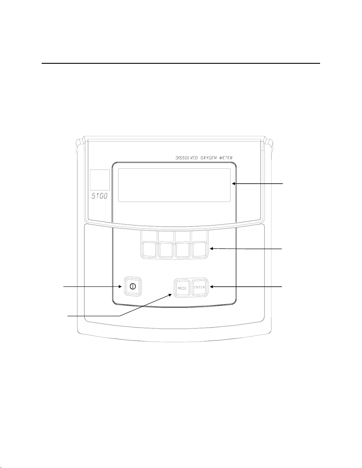
4.1 Front Panel
The front panel of the instrument contains the display and keypad as shown below. The front
panel display and controls of the 5000 and 5100 are identical.
Display
Power
ON/OFF
MODE Key
Soft-Keys
ENTER Key
6
Page 10
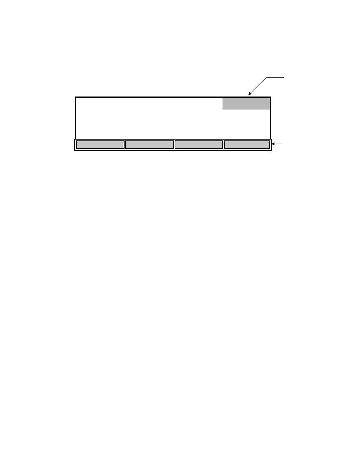
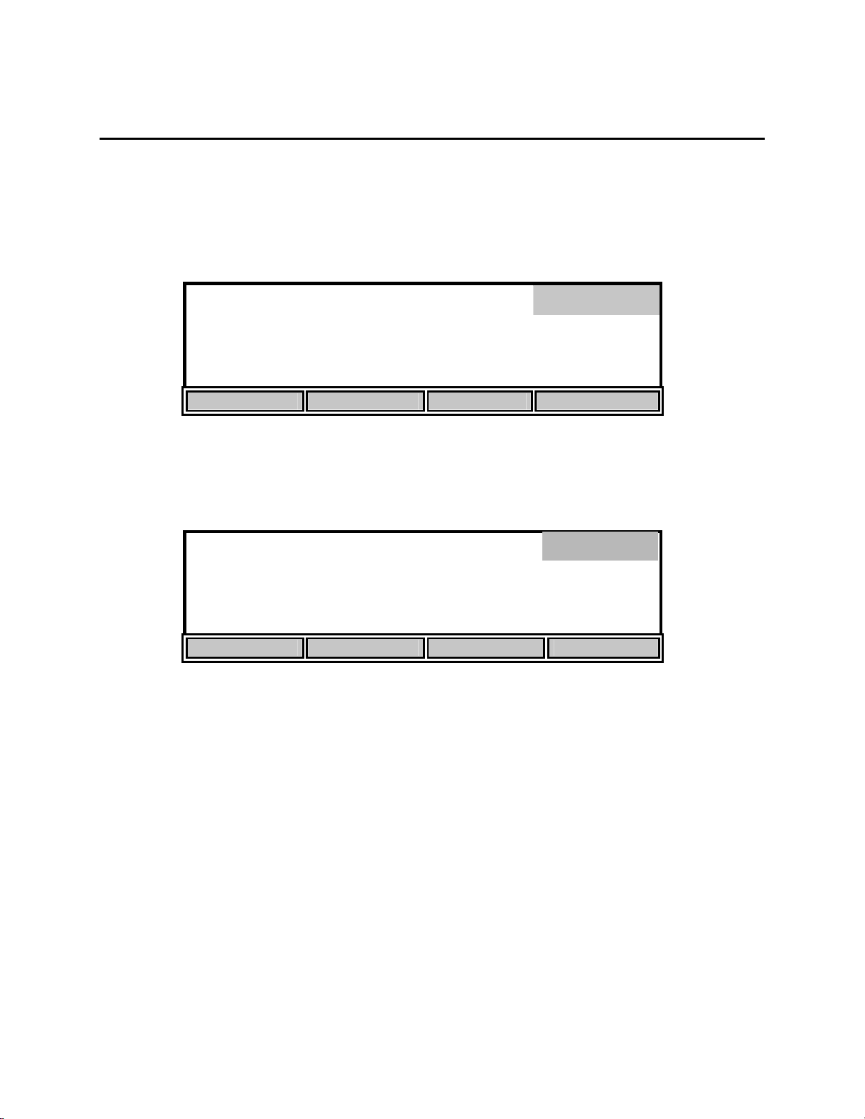
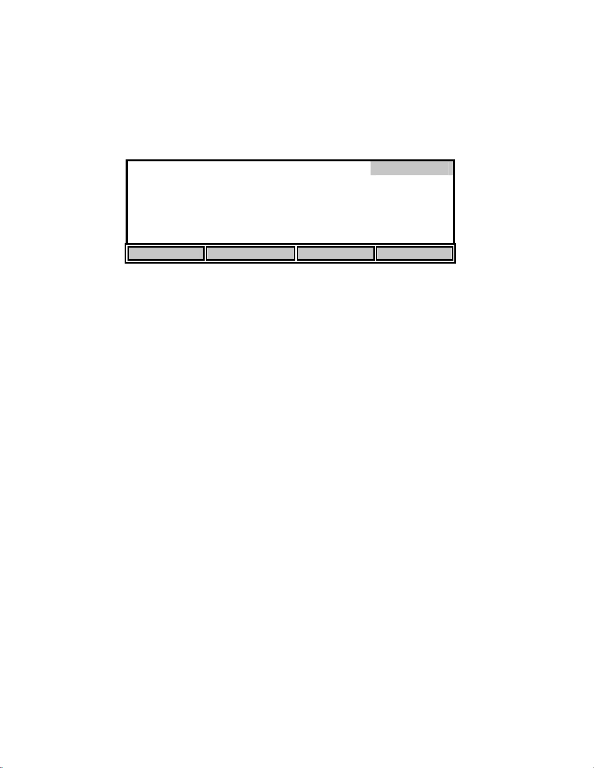
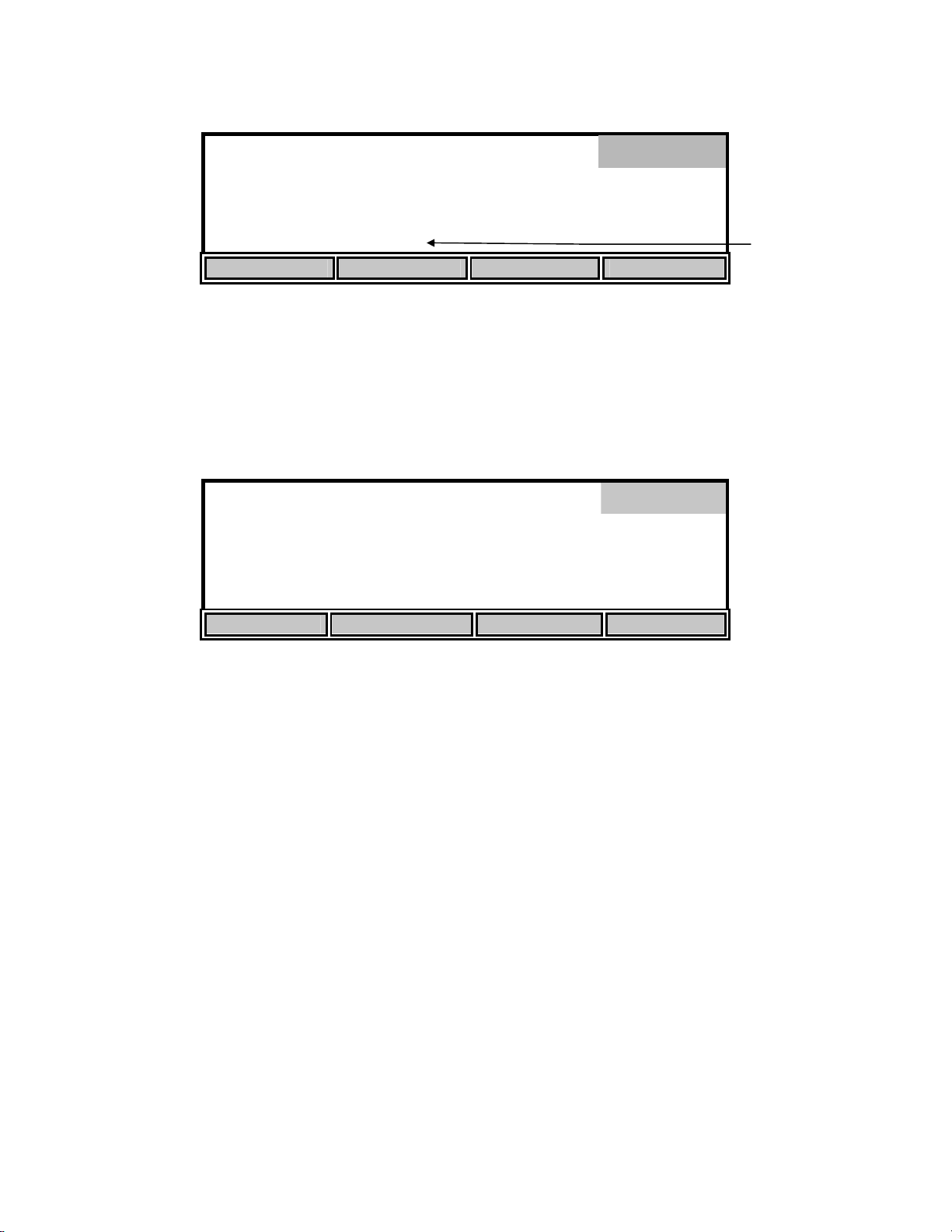
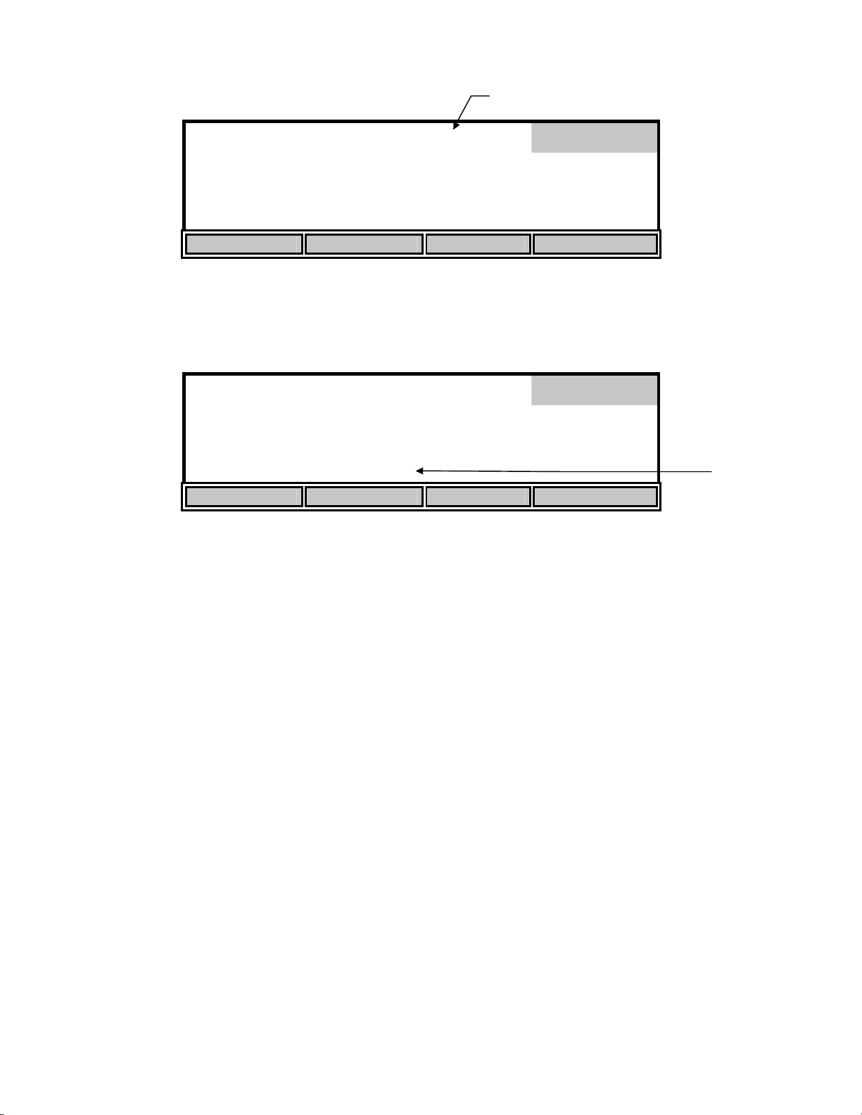
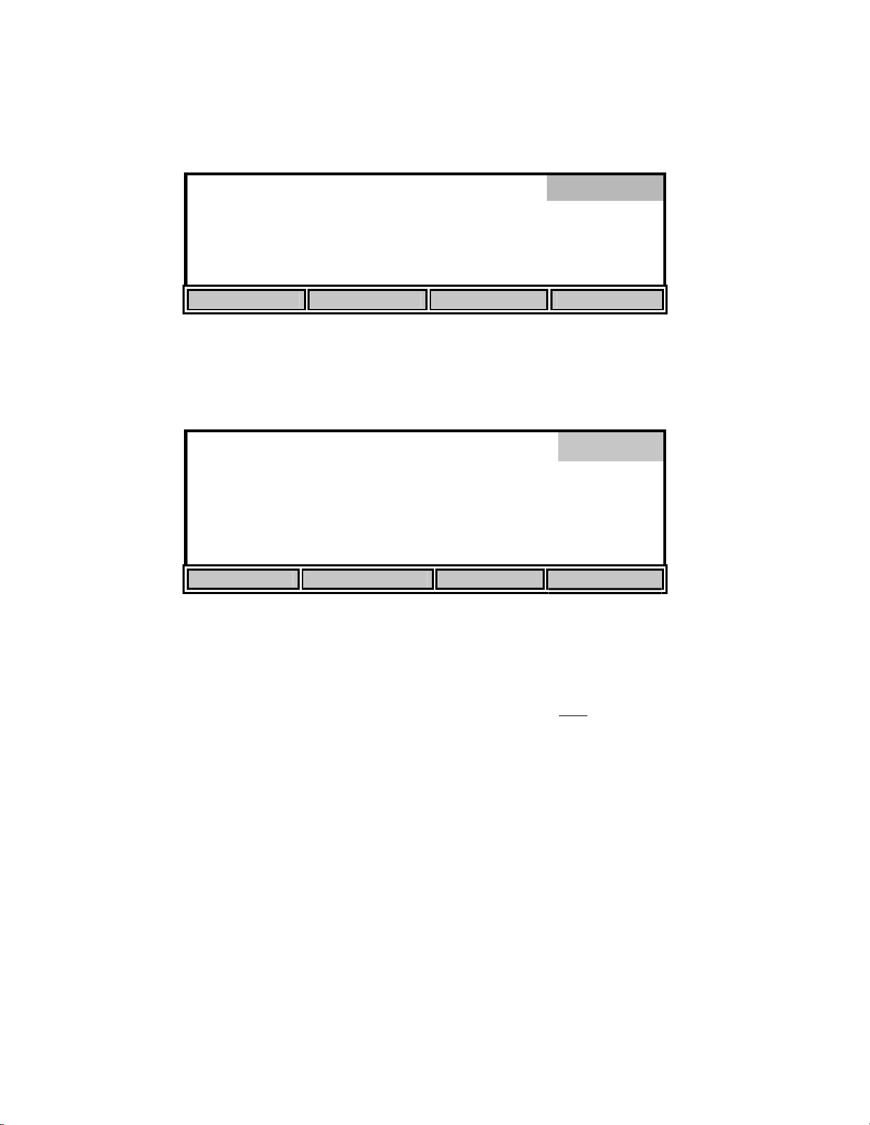
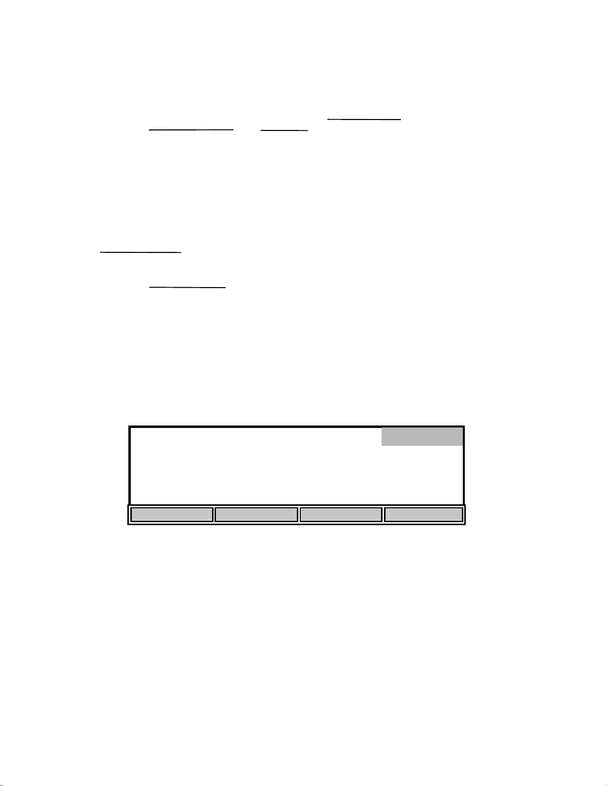
The 5000/5100 has two main operating modes, Main and Application. The current mode is
displayed in the dark bar at the top right corner of the display. The following diagram shows the
display while the instrument is in the Main mode.
Main
Mode
mg
8.15*
/L
24.38°C 11:33AM
STORE REVIEW SEND CALIBRATE
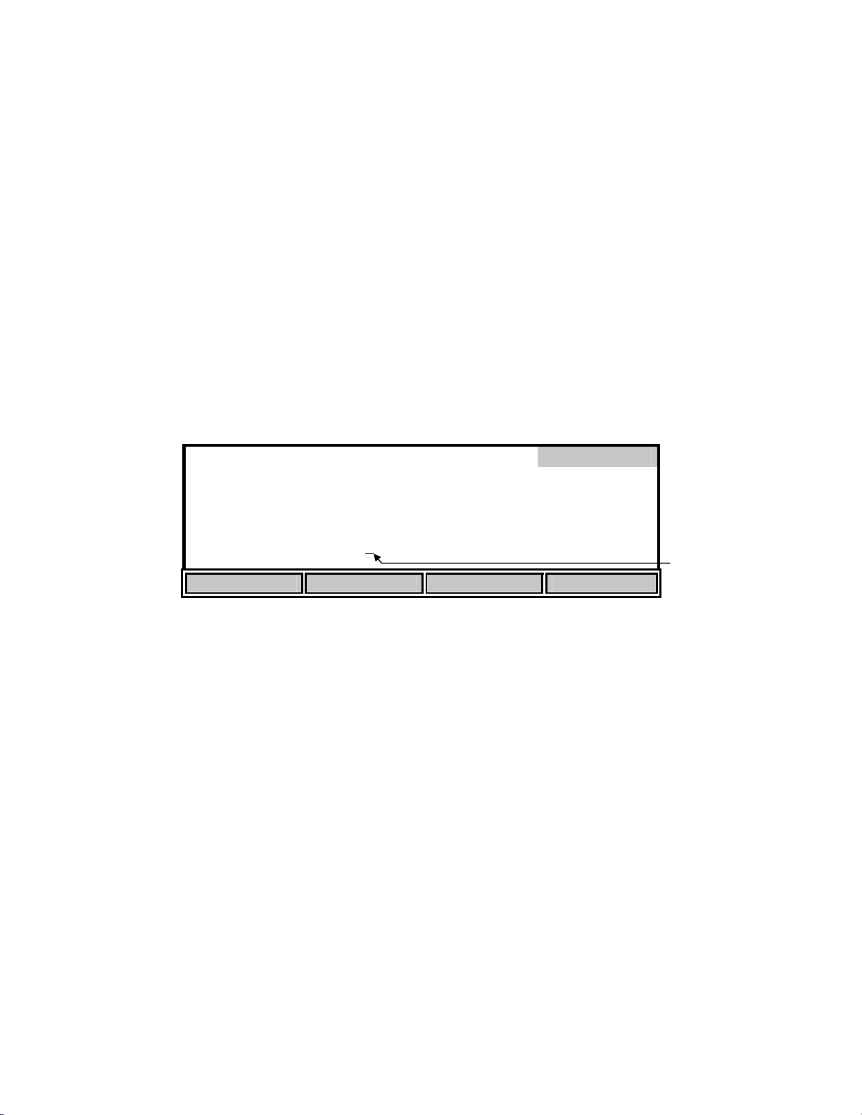
The bottom row of the display identifies the function of the four soft-keys which are located on
the keypad below the display. The function of each of these keys changes with each mode.
The [Mode] key and soft-keys are used to navigate through the menus. The [Mode] key is used to
cycle between the two main operating modes. Pressing a soft-key will bring up a new set of softkey functions (menu). The [Mode] key is also used to backup through the menus to the top level.
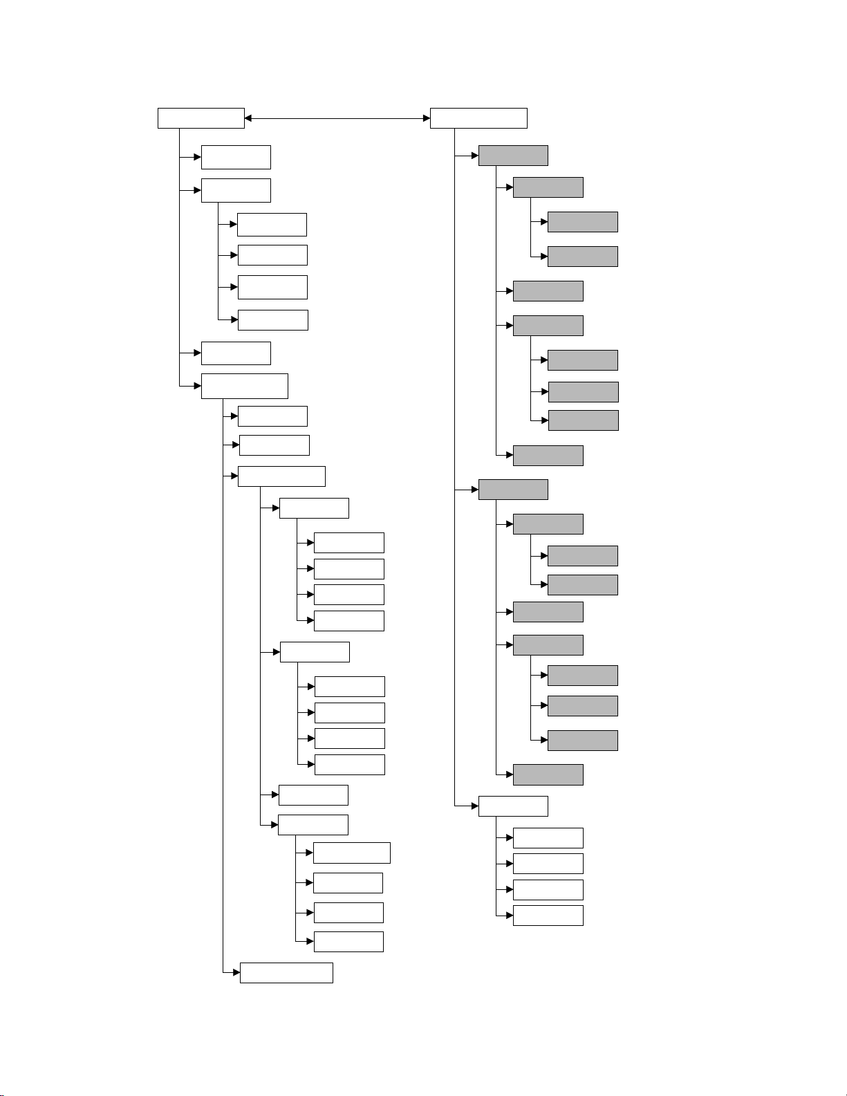
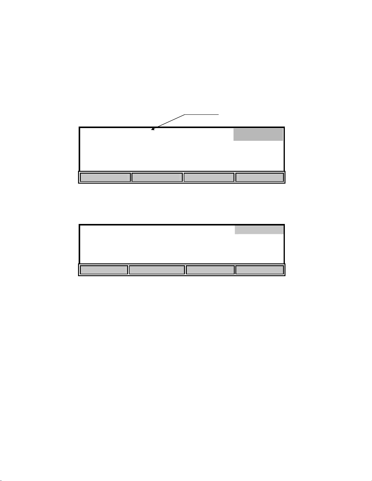
4.2 Software Flow Chart
The following section shows the software flow chart for the 5000/5100. The two operating
modes, Main and Application, are shown at the top with the soft-key functions that are accessed
in each mode below them. Functions in shaded boxes are only available on the model 5100.
Soft-key
functions
7
Page 11
5000/5100 Software Flow Chart
A
A
MAIN
Store
Review
Send
Calibrate
Recall
Send All
Clear
Delete All
uto Cal
DO Cal
Setup
Display
Size
Unit
Contrast
Last Digit
APPLICATION
OUR
Start
End
Send on/off
Setup
Review
Next Rec.
Modify
Send
Send
SOUR
Start
End
Send on/off
Setup
Report
SDF
CDF
Range
Next
Stable
System
udio On/Off
Time/Date
Version
RS-232
Diagnostic
NOTE: Shaded boxes are only available
on the model 5100
8
Review
Next Rec.
Modify
Send
Send
Remote
Skip
Up
Down
Confirm
.
Page 12
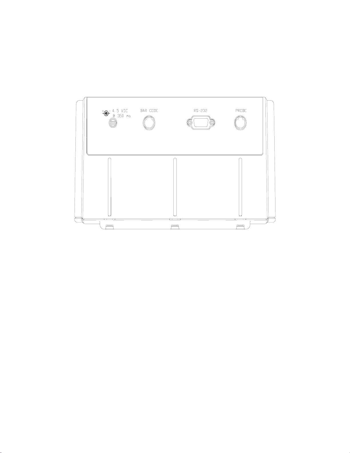
4.3 Rear Panel
The rear panel contains the connections for the power supply, probe, bar code reader, external
computer keyboard and RS232 serial port as shown below. The bar code reader and external
computer keyboard share the same socket and are only available on the model 5100.
Power Supply Connection
The power supply connection requires a 4.5 to 5.5 VDC power supply with at least 350 mA
current (6.0 VDC 800 mA when using the YSI 5015 bar code reader).
Probe Connection
The connector for the probe is an 8-pin mini DIN connector and is marked with an arrow to show
proper alignment. Be sure to align the arrows when plugging in the probe.
YSI 5000 series probes, such as the YSI 5010 BOD probe, will plug directly into the 5000/5100.
If you have an older YSI 5700 or 5900 series probe, the YSI 5011 adapter will be required.
The YSI 5011 adapter has a mini-DIN connector at one end and a 5-pin MS connector and probe
power connector at the other end. The 8-pin mini-DIN connector plugs into the 5000/5100 probe
socket and the 5-pin MS connector plugs into a 5700 or 5900 series probe/cable. The power
connector plugs into the matching connector on a self stirring BOD probe. This allows the
5000/5100 to power the BOD probe, eliminating the need for a separate probe power supply.
NOTE: Do NOT plug the 5011 adapter power connector into the 5000/5100 power supply
socket. Doing so will prevent the 5000/5100 from operating.
9
Page 13

Bar Code Reader Connection
The YSI 5015 bar code reader connects to this 6-pin mini DIN connector. The connector is
marked with an arrow to show proper alignment. Be sure to align the arrows when plugging in
the YSI 5015 bar code reader (see 7.2 Application Mode, Remote,
Bar Code Reader).
The bar code connector is also used for attaching an external computer keyboard. Using a
keyboard simplifies data entry when using the 5100 in the remote mode, such as with YSI BOD
Analyst software (see 7.2 Application Mode, Remote).
RS232 Connection
The RS232 connection is a standard DB9 connector. See 7.2 Application Mode, Remote, System
Setup for details.
10
Page 14
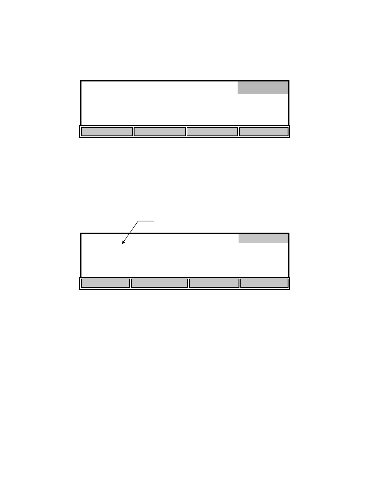
5. Setup
Before operating the 5000/5100 for the first time, you should set the instrument parameters. Once
set, these parameters are maintained in memory. These parameters are discussed below.
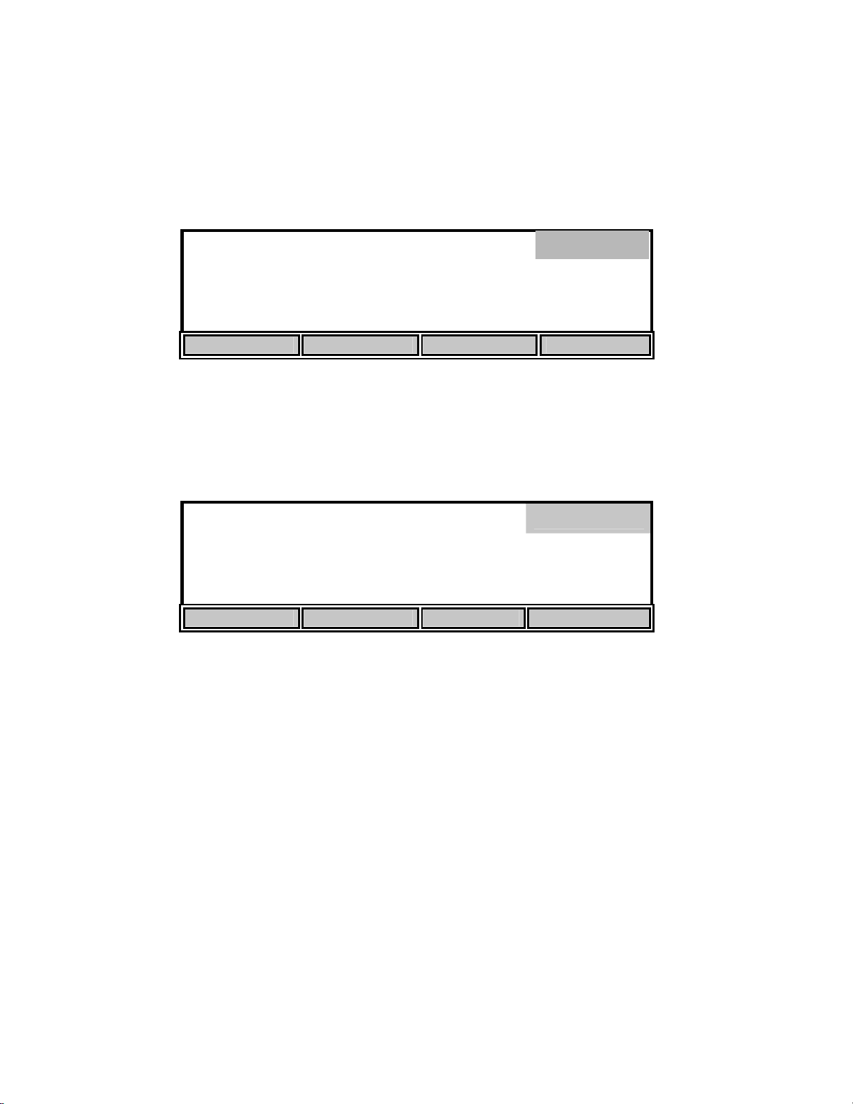
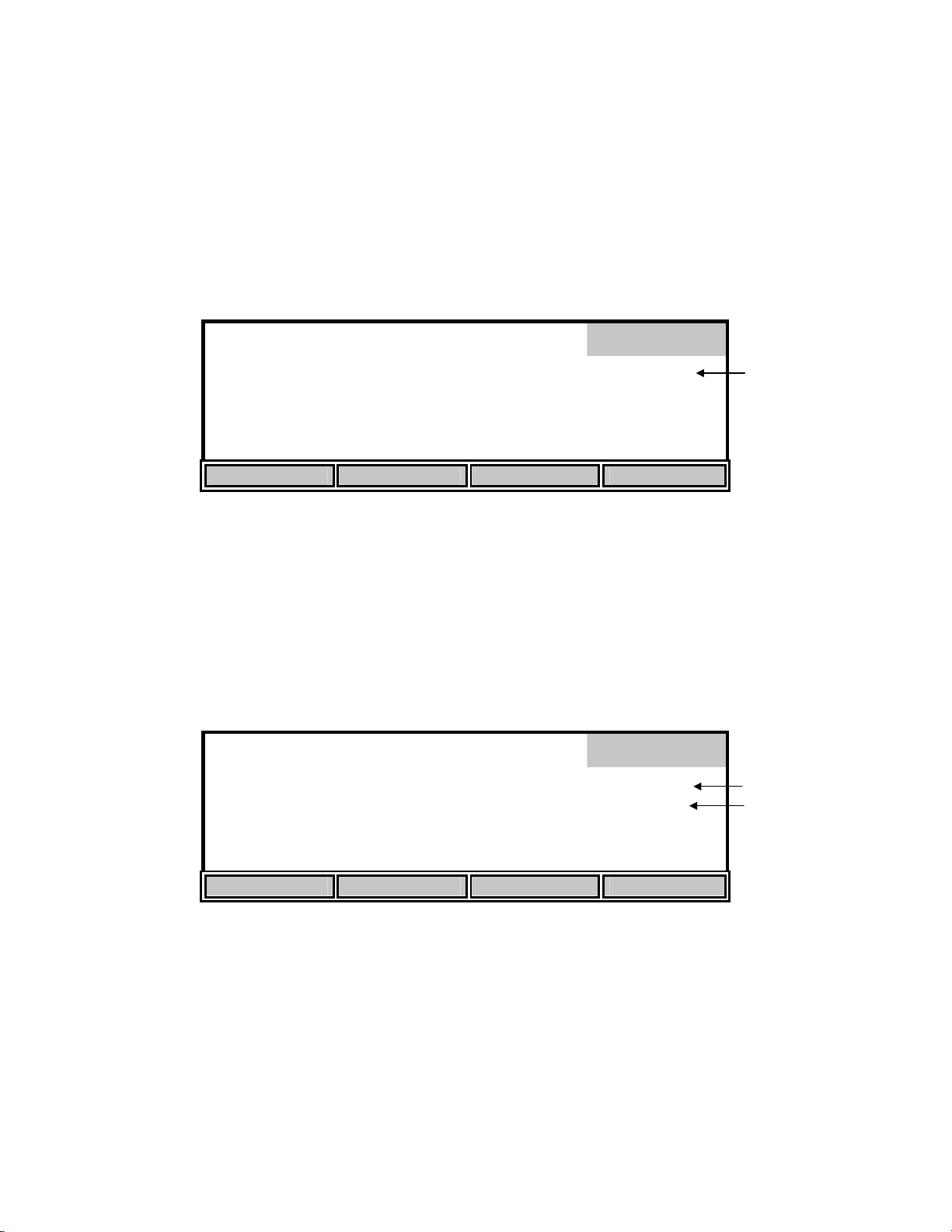
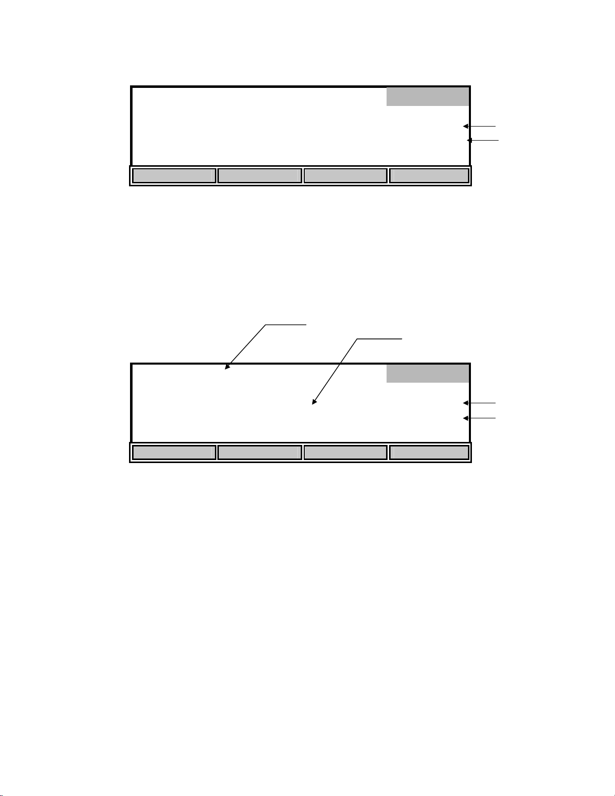
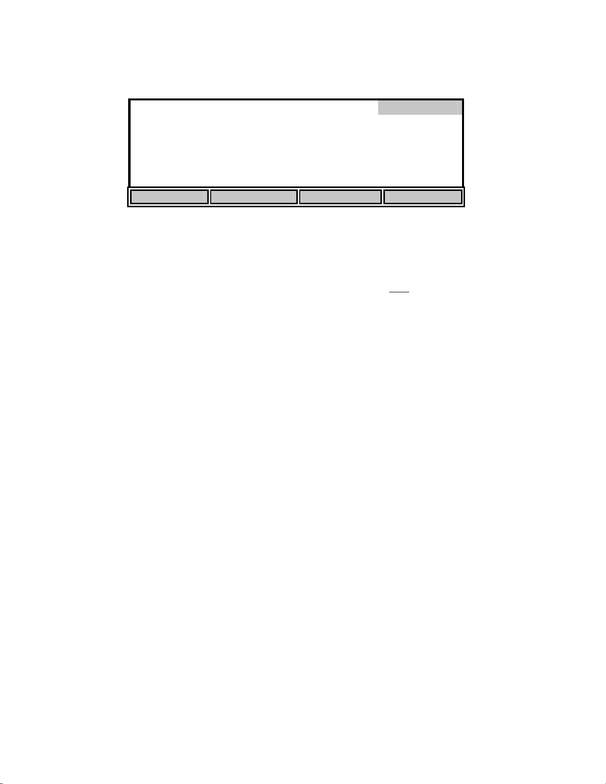
From Main mode, press the [CALIBRATE] soft-key to enter the calibration menu. Notice that
the dark bar in the top right corner of the display shows the current mode.
98.0 % 8.15
ppt
0.0
740
mg/L
mmHg
Calibrate
24.38°C 11:33AM
AUTO CAL DO CAL SETUP DIAGNOSTICS
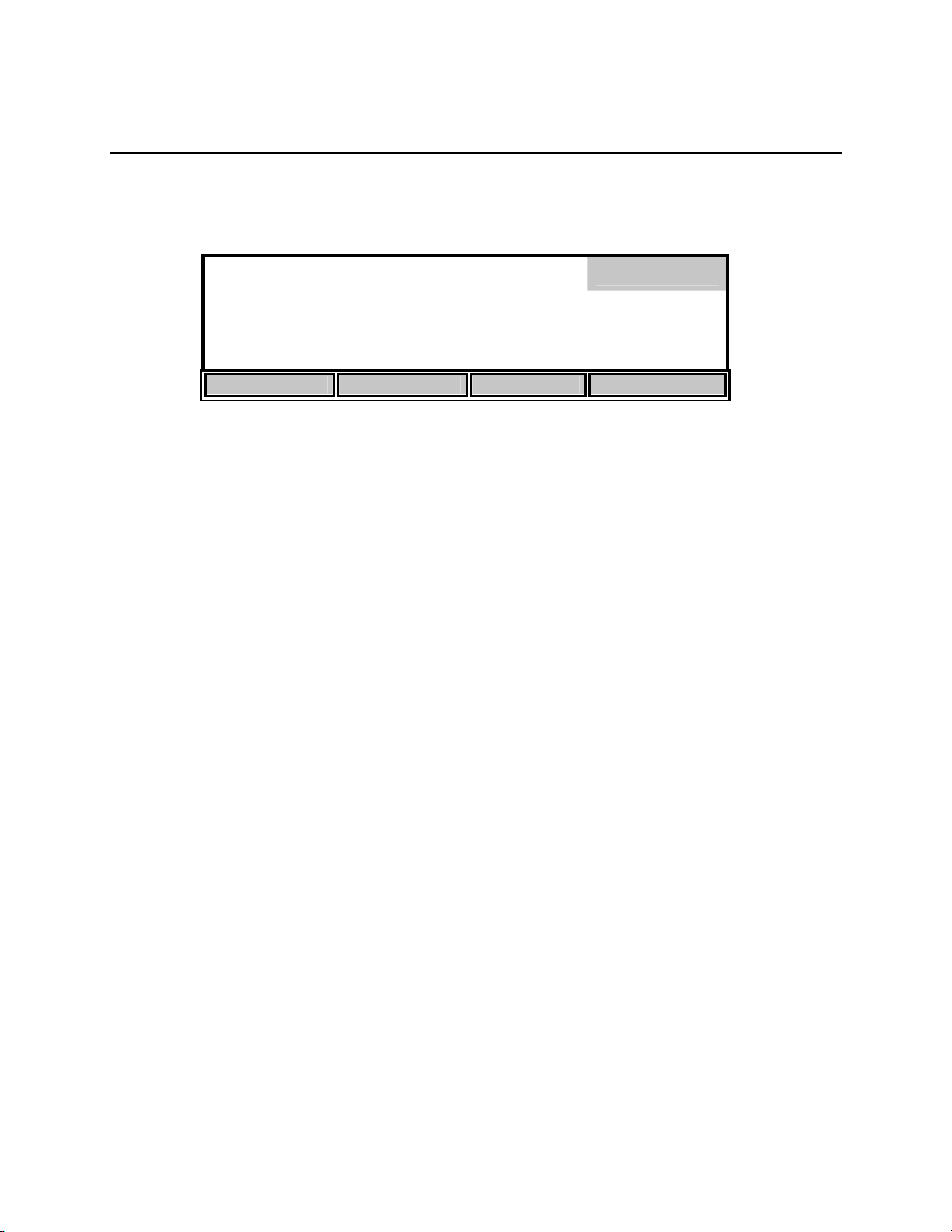
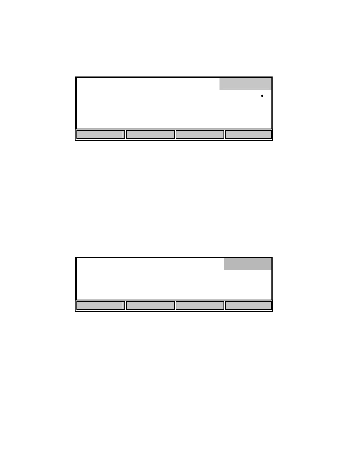
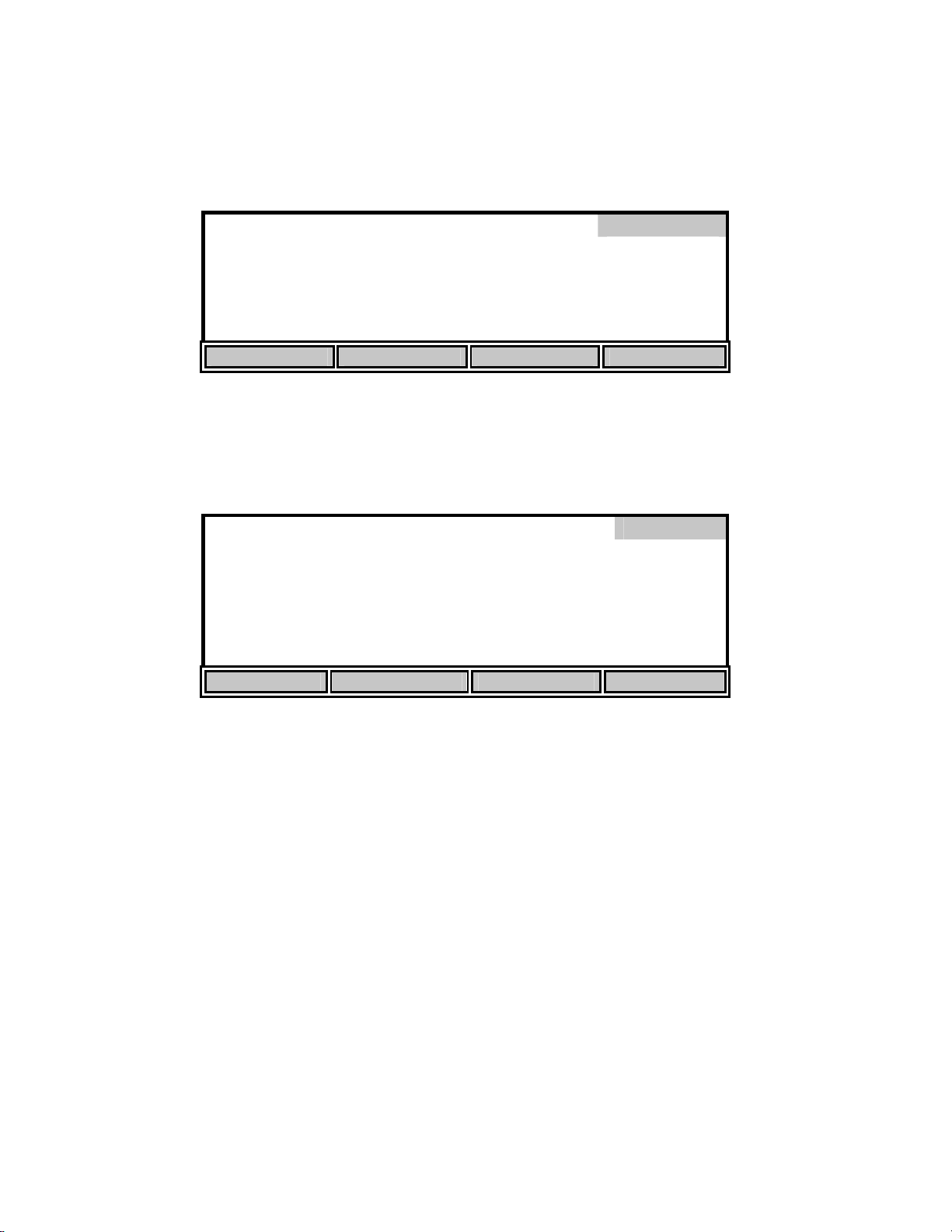
Next, press the [SETUP] soft-key to enter the Setup menu. The bottom row of the display will
show the following soft-key setup selections.
Setup
mg
8.15*
/L
24.38°C 11:33AM
DISPLAY REPORT STABLE SYSTEM
These four selections are used to change the instrument setup.
11
Page 15
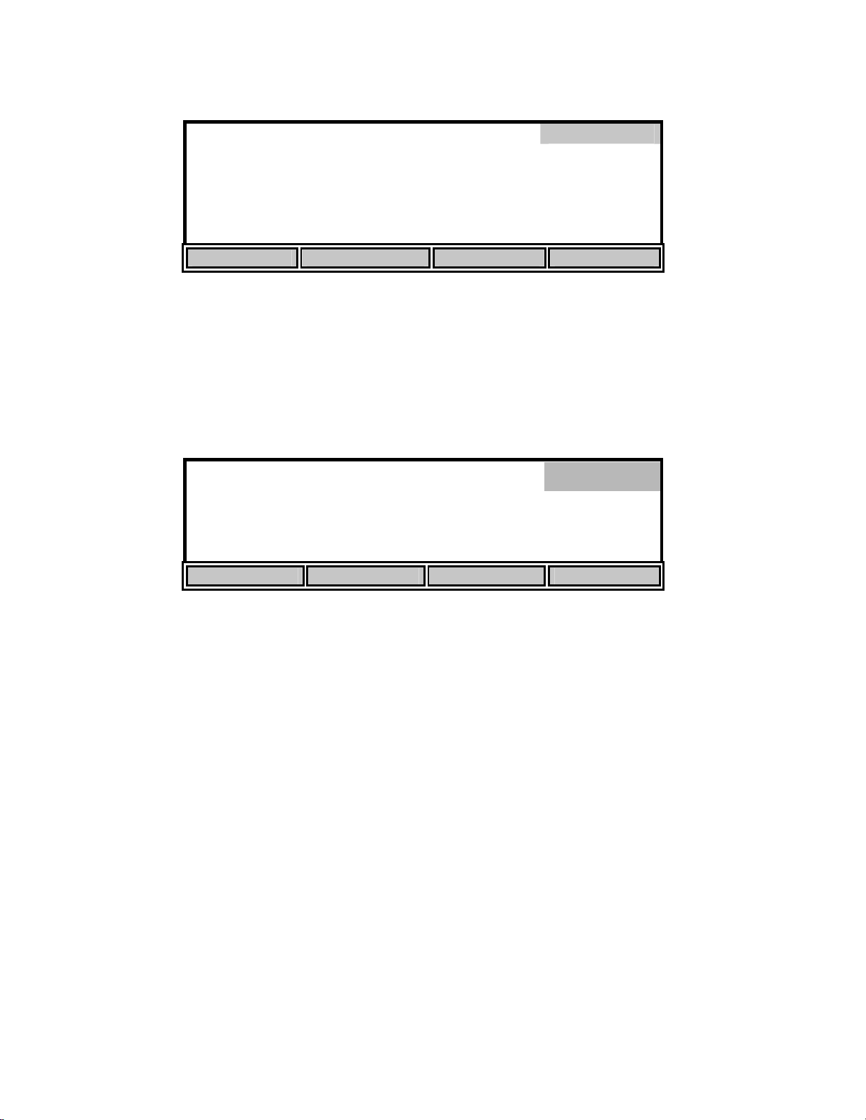
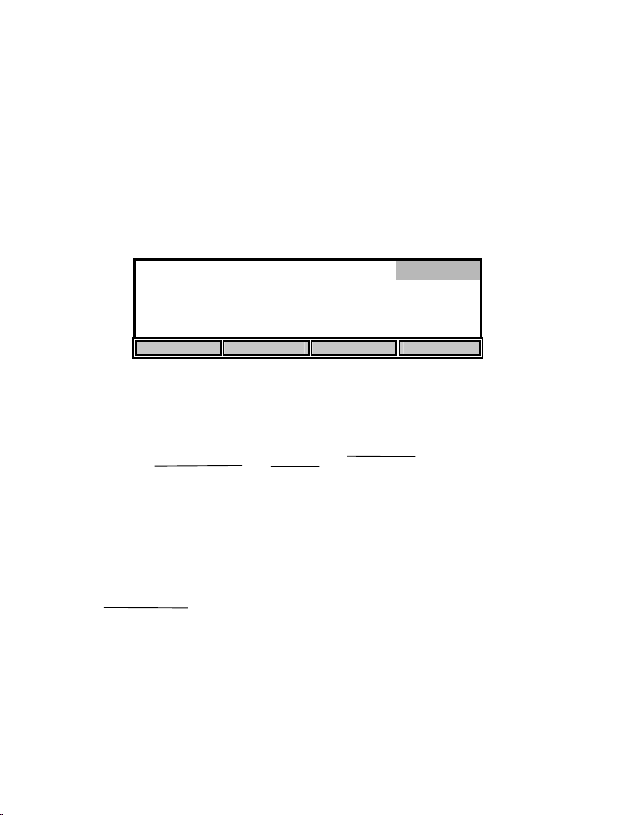
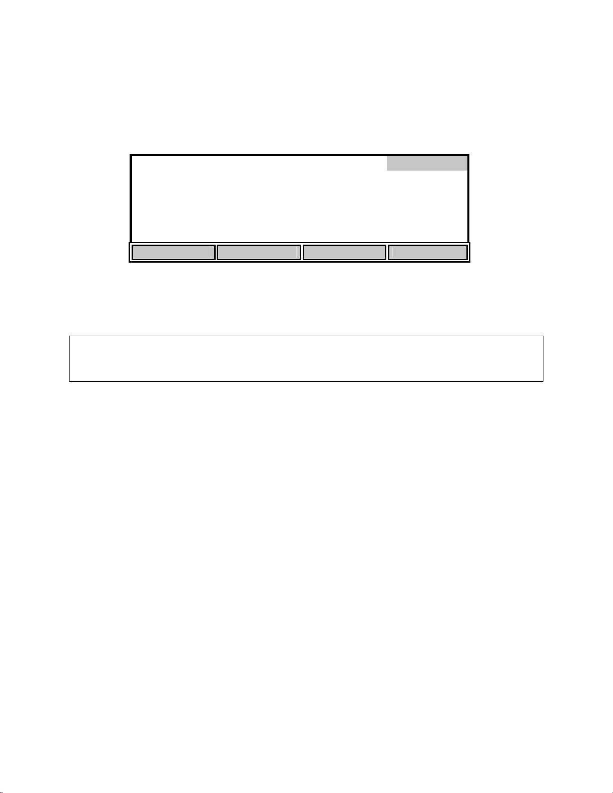
5.1 Display Setup
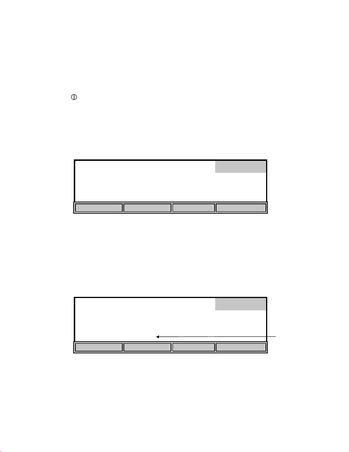
Press the [DISPLAY] soft-key to show the following menu.
Display
mg
8.15*
/L
24.38°C 11:33AM
SIZE UNITS CONTRAST LAST DIG.
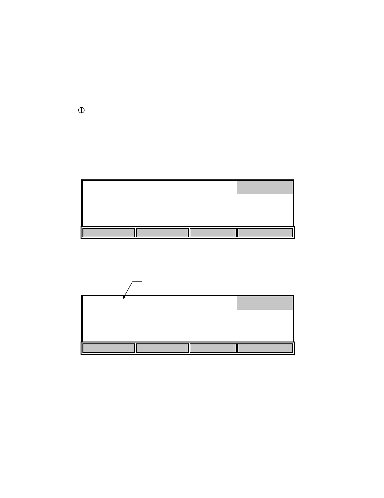
The [SIZE] soft-key cycles among the two possible display arrangements for Main mode. One
selection shows as many parameters as possible, the other shows Dissolved Oxygen in large type
with temperature and time in small type. These different display arrangements are for Main mode
only. The display will show all parameters in Calibration mode.
98.0% 8.15
ppt
0.0
740
mg/L
mmHg
Display
24.38°C 11:33AM
SIZE UNITS CONTRAST LAST DIG.
The [UNITS] soft-key brings you to the [UNITS] menu. Use the [UP] and [DOWN] soft-keys to
change the measurement units. If you have selected the size to be large, only the DO units
selected on the [UNITS] screen will be shown. When the size is set to small, both % and mg/L
will be shown. The Date Format is also used to change from a 2 digit year to 4 digit year. The
Sal – 78 scale give salinity in unitless values as the measurements are in reference to the
conductivity of standard seawater at 15 °C. The HOUR units switch from a 12 to 24 hour day.
Press the [MODE] key to return to the Display menu.
12
Page 16
[
[
[
[
[
[
]
DISPLAY UNIT SETUP
D.O.
Barometer
Salinity
Temperature
Date Format
UP DOWN NEXT
The [CONTRAST] soft-key allows the user to change the display contrast. The display contrast
will change slightly each time the [UP] or [DOWN] soft-key is pressed.
The [LAST DIG.] soft-key allows the user to suppress the last digit of the DO reading. This
function is only available when the large size display has been selected. The small size display
will not be affected.
% ]
in Hg ]
Sal – 78 ]
C ]
MM/DD/YY ] HOUR
mg
8.2*
/L
Units
12H
Display
24.38°C 11:33AM
SIZE UNITS CONTRAST LAST DIG.
Press the [MODE] key to return to the Setup menu. If you wish to return to Main mode, press
[MODE] two more times.
13
Page 17
[*]
[*]
[*]
[*]
[*]
[*]
[*]
]
5.2 Report Setup
From the Setup menu, press [REPORT] to display the following soft-keys.
[SDF] Space Delimited Format
SAMPLE ID #
DO%
DO mg/L
DATE
TIME
BAROMETER
TEMPERATURE [*] SALINITY
SEND Record from [ 0] to [99
SDF CDF RANGE NEXT
The display lists the parameters that can be included in the output string at the RS232 serial port,
the default set has everything selected for inclusion.
You can select the report format that you wish to use by pressing the [SDF] or [CDF] soft-key.
Select [SDF] for Space Delimited Format (standard text). If you are going to import the data to a
spreadsheet, select [CDF] for Comma Delimited Format. The following are examples of each
format:
Report
Space Delimited Format
SAMPLE ID mg/L % C ppt mmHg TIME DATE
ID: 0 7.95 97.3 25.6 0.0 786 15:06:34 01/23/96
ID: 1 7.94 97.1 25.6 0.0 786 15:06:36 01/23/96
ID: 2 7.95 97.2 25.6 0.0 785 15:06:44 01/23/96
14
Page 18
[*]
[*]
[*]
[*]
[*]
[*]
[*]
Comma Delimited Format
"SAMPLE ID","mg/L","%","C","ppt","mmHg","TIME","DATE"
"ID: 0", 7.95, 97.3,25.6, 0.0, 786,"15:06:34","01/23/96"
"ID: 1", 7.94, 97.1,25.6, 0.0, 786,"15:06:36","01/23/96"
"ID: 2", 7.95, 97.2,25.6, 0.0, 785,"15:06:44","01/23/96"
The asterisk character in front of each parameter indicates that the parameter will be included in
the report. Press the [NEXT] soft-key to select the parameter that you want to change. Then press
[ENTER] to turn the asterisk character on or off.
NOTE: After pressing [SDF] or [CDF] to choose the report format, press the [MODE] key to exit
the Report menu. Do NOT press [ENTER] as this will change the currently selected parameter.
To return to Main mode, press [MODE] two more times.
The [RANGE] soft-key brings up the following soft-key menu.
[SDF] Space Delimited Format
SAMPLE ID #
DO%
DO mg/L
DATE
TIME
BAROMETER
Report
TEMPERATURE [*] SALINITY
SEND Record from [ 00] to [99]
UP DOWN DIGIT NEXT
Flashing Cursor
This menu allows specifying a specific range of memory locations for the report. The default
range is 00 - 99 and empty locations will not be sent to a computer or serial printer.
The display digit that has the flashing cursor below it is increased or decreased by pressing the
[UP] or [DOWN] soft-key. If the [UP] or [DOWN] soft-key is held down, the digit will continue
to change until the key is released. The [DIGIT] soft-key makes it easy to make large changes by
selecting the digit you wish to change. Press the [NEXT] soft-key to change between the
minimum and maximum parameter. When the desired number is obtained, pressing [ENTER]
will accept the number and exit the RANGE sub-menu. The RANGE sub-menu can be left
without making any changes by pressing the [MODE] key. Operation returns to the report setup
menu.
To return to Main mode, press [MODE] three more times.
15
Page 19
[
[
)
5.3 Autostable Setup
The autostable feature indicates when readings are stable by emitting a single beep and
displaying an asterisk (*) to the right of the dissolved oxygen reading. The instrument uses
criteria that you input to determine what a stable reading is. You select the maximum percent of
change that may occur during a selected time duration. The default values are 10 seconds and
0.4% variation. The instrument will display an asterisk (*) only when these criteria are met.
mg
Stable reading indication
Main
8.20*
/L
24.38°C 11:33AM
STORE REVIEW SEND CALIBRATE
From the Setup menu, press the [STABLE] soft-key to display the following menu.
PARAMETERS
10] Time Duration (3-19) Seconds
0.4] DO % variation (0.0-1.9
UP DOWN DIGIT NEXT
This menu is used to change the autostable criteria. Press the [NEXT] soft-key to select between
the time duration and the percent variation. Use the [DIGIT] soft-key to select the digit you wish
to change by pressing [UP] or [DOWN]. When you have finished setting the parameters, press
[ENTER] to confirm. The STABLE sub-menu can be left without making any changes by
pressing the [MODE] key instead of [ENTER]. Operation returns to the setup menu.
Stable
If you wish to disable the autostable feature, set the DO% variation to 0.0.
To return to Main mode, press [MODE] two more times.
16
Page 20
5.4 System Setup
From the Setup menu, press the [SYSTEM] soft-key to display the following menu.
mg
System
8.38*
/L
24.38°C 11:47AM
AUDIO off TIME / DATE VERSION RS232
The [AUDIO on/off] soft-key allows setting the beeper on or off. The key toggles between an
[AUDIO off] soft-key and an [AUDIO on] soft-key. The present state of the beeper would be the
OPPOSITE of the function shown on the soft-key. If the beeper is currently on, the soft-key
shows “AUDIO off”; i.e., your alternate choice.
The [TIME/DATE] soft-key brings up the following menu to allow setting of the date and time.
Flashing Digit
Time/Date
09:58:04
01/20/96
UP DOWN DIGIT NEXT
Use the UP, DOWN, DIGIT and NEXT soft-keys to enter the time in 24-hour format. The
display digit that is flashing is increased or decreased by pressing the [UP] or [DOWN] soft-key.
If the [UP] or [DOWN] soft-key is held down, the digit will continue to change until the key is
released. The [DIGIT] soft-key makes it easy to make large changes by selecting the digit you
wish to change. After you have set the hour, press the [NEXT] soft-key to move to the next
parameter, minutes. Repeat the process for the remaining parameters.
When you have finished entering the time and date, press [ENTER] to confirm and return to the
system setup menu. The message
at the bottom of the screen. The Time/Date sub-menu can be left without making any changes by
pressing the [MODE] key instead of [ENTER]. Operation returns to the system setup menu.
“TIME SETTING SAVED” will be displayed on the message line
17
Page 21
mg
System
8.38*
/L
24.38°C 9:59AM
TIME SETTING SAVED
AUDIO off TIME / DATE VERSION RS232
If you wish to return to Main mode, press [MODE] three times.
The [VERSION] soft-key displays the instrument software version on the message line of the
display just above the soft-key descriptions.
The [RS232] soft-key displays the RS232 setup.
[ 2 ] BAUD RATE 19200
0. 4. 4800
1. 5. 2400
2. 19200 6. 1200
3. 9600
UP DOWN
RS232
Message
Select the baud rate by pressing the [UP] or [DOWN] soft-keys. The first two choices, 0 and 1,
are not currently available.
The remaining RS232 parameters are fixed as follows:
Data Length: 8 bits
Parity: None
Stop Bits: 1
Press [ENTER] to confirm. The RS232 sub-menu can be left without making any changes by
pressing the [MODE] key instead of [ENTER]. Operation returns to the system setup menu.
Press [MODE] to return to the previous menu, Setup. To return to Main mode, press [MODE]
two more times.
18
Page 22
6. Calibration
From the Main mode, press the [CALIBRATE] soft-key to enter Calibration mode. The bottom
row of the display shows the soft-key menu.
98.0*% 8.15
ppt
0.0
740
mg/L
mmHg
Calibrate
24.38°C 11:33AM
AUTO CAL DO CAL SETUP DIAGNOSIS
6.1 Dissolved Oxygen Calibration
Dissolved oxygen calibration can be done automatically with the push of one button (see Auto
Cal) or manually by entering the desired value in milligrams per liter or percent saturation (see
DO Cal).
BEFORE YOU CALIBRATE you must Setup the meter, as discussed in the Setup section of
this manual, and Prepare the DO probe as discussed in the Probe Operations Manual. Before
performing an AUTO CAL on a Model 5100, you must check the barometric pressure reading
and calibrate the barometer, if necessary, as shown under 6.1 Dissolved Oxygen Calibration,
Barometer. The Model 5000 does not contain a barometer, therefore, the current barometric
pressure must be entered before an AUTO Cal is performed.
Dissolved oxygen calibration must be done in an environment with a known oxygen content.
Three such environments will be discussed here: calibration in air (water saturated), calibration
in air-saturated water and calibration by Winkler titration. Choose the one which best fits your
application. Calibration in air is the simplest and most accurate method of calibration.
• For air calibration, place the probe in air at 100% relative humidity. To achieve this, the
probe can be placed in a BOD bottle containing 1″ of water. No stirring is required in air.
• For air-saturated water calibration, air-saturate a volume of water (300 to 500 mL) by
aerating for at least 15 minutes at a relatively constant temperature. Place the probe in the
aerated water and provide adequate stirring (at least 1 foot per second) while calibrating, such
as that provided by the 5010 self-stirring BOD Probe.
• To calibrate to a Winkler-titrated sample, determine the dissolved oxygen value of a
sample by Winkler titration. Place the probe in the sample and provide adequate stirring (at
least 1 foot per second) while calibrating in the manual mode.
NOTE: If you choose calibration by Winkler titration, you cannot use AUTO CAL, you must use
DO CAL (manual) mode, since AUTO CAL assumes the probe is in a saturated environment.
19
Page 23
Auto Cal
1. Prepare the probe according to the instructions in the Probe Operations Manual.
2. Connect the probe to the meter.
3. Place the probe in a BOD bottle containing about 1″ of water to provide a 100% relative
humidity environment.
4. Press [ ] to turn the instrument on.
5. Allow the probe to polarize and the temperature to stabilize for at least 15 minutes. If
calibration is performed prematurely the values will drift and may be out of specification.
6. Press the [CALIBRATE] soft-key to change to Calibration mode. The following display will
appear.
98.0*% 8.15
ppt
0.0
740
mg/L
mmHg
Calibrate
24.38°C 11:33AM
AUTO CAL DO CAL SETUP DIAGNOSIS
7. Model 5100: Verify that the barometer reading is correct. Calibrate the barometer, if
necessary, as shown under 6. Dissolved Oxygen Calibration, Barometer.
Model 5000: Enter the current barometric pressure as shown under 6. Dissolved Oxygen
Calibration, Barometer.
8. Make sure that the display readings are stable, then press the [AUTO CAL] soft-key to
calibrate Dissolved Oxygen. The message “
a few seconds.
98.0*% 8.15
ppt
0.0
740
D.O. CALIBRATION SAVED” will be displayed for
mg/L
mmHg
Calibrate
24.38°C 11:33AM
D. O. CALIBRATION SAVED
AUTO CAL DO CAL SETUP DIAGNOSIS
9. Press [MODE] to return to the Main mode. The instrument is now calibrated and ready to
measure dissolved oxygen and temperature. See 7.1 Main Mode, Making Measurements.
20
Message
Page 24
DO Cal (manual)
1. Prepare the probe according to the probe instructions.
2. Connect the probe to the meter.
3. Place the probe in a known oxygen environment, such as a BOD bottle containing about 1″ of
water to provide a 100% relative humidity environment or a Winkler-titrated sample.
4. Press [ ] to turn the instrument on.
5. Allow the probe to polarize and the temperature to stabilize for at least 15 minutes. If
calibration is performed prematurely the values will drift and may be out of specification.
6. Press the [CALIBRATE] soft-key to change to Calibration mode. The following screen will
be displayed.
98.0*% 8.15
ppt
0.0
740
mg/L
mmHg
Calibrate
24.38°C 11:33AM
AUTO CAL DO CAL SETUP DIAGNOSTICS
7. Press the [DO CAL] soft-key to enter the manual DO calibration menu.
98.0*% 8.15
ppt
0.0
Flashing digit
mg/L
740
mmHg
Cal %
24.38°C 11:33AM
UP DOWN DIGIT NEXT
8. Make sure that the display readings are stable, then enter the calibration value in percent
saturation, using the [UP], [DOWN] and [DIGIT] soft-keys. See Appendix A - Oxygen
Solubility Table and Appendix B - Pressures and Altitudes for manual calibration data.
If you wish to calibrate in milligrams per liter (instead of percent), verify that the salinity is set to
the salinity value of the calibration environment (0.0 ppt for air calibration, see 6.1 Dissolved
Oxygen Calibration, Salinity). Then, use the [NEXT] soft-key to select mg/L and enter the
calibration value in milligrams per liter as shown below.
21
Page 25
98.0*% 08.15
0.0
ppt
740
mmHg
Flashing digit
mg/L
Cal mg/L
24.38°C 11:33AM
UP DOWN DIGIT NEXT
9. Press [ENTER] to confirm your calibration. The screen will momentarily display
CALIBRATION SAVED”
98.0*% 8.15
as shown below.
ppt
0.0
740
mg/L
mmHg
Calibration
24.38°C 11:33AM
D. O. CALIBRATION SAVED
UP DOWN DIGIT NEXT
“D.O.
Message
NOTE: If you wish to abort calibration before you have pressed [ENTER], you may press
[MODE] to return to the calibrate menu without saving the new calibration value. You may
also press [NEXT] to select a different parameter (any change made will not be saved).
10. Press [MODE] to return to the Main mode. The instrument is now calibrated and ready to
measure dissolved oxygen and temperature. See 7.1 Main Mode, Making Measurements.
Barometer
The YSI Model 5100 has an internal barometer for pressure compensation during AUTO
Dissolved Oxygen Calibration. This barometer only needs to be calibrated when it is no longer
reading the correct barometric pressure. If the 5100 is kept at a fairly constant ambient
temperature (±10°C), the barometer calibration should be accurate for approximately 30 days.
The Model 5000 does not contain a barometer, therefore, the current barometric pressure must be
entered before an AUTO Cal is performed. The pressure value displayed is the setting that was
entered and stored during the previous calibration.
From the calibration menu press the [DO CAL] soft-key, then press the [NEXT] soft-key until
the barometric pressure is flashing and “Barometer” appears in the top right corner of the display
as follows:
22
Page 26

mg/L
98.0*% 8.15
0.0
ppt
0740
mmHg
Flashing digit
Barometer
24.38°C 11:33AM
Press ENTER to SAVE SETTING
UP DOWN DIGIT NEXT
Using the [UP], [DOWN] and [DIGIT] soft-keys, enter the true local barometric pressure. This
corresponds to a reading from a mercury barometer. Do NOT use the pressure reported by the
weather bureau. Weather bureaus correct pressures to sea level.
NOTE: You may estimate
and Altitudes.
Press [ENTER] to confirm. The message
the model 5100, as shown below. The model 5000 will display
since it does not contain an internal barometer.
the standard pressure at your altitude by using Appendix B - Pressures
“PRESSURE CALIBRATION SAVED” will be displayed, on
“PRESSURE SETTING SAVED”,
98.0*% 8.15
ppt
0.0
740
mg/L
mmHg
Calibrate
24.44°C 11:34AM
PRESSURE CALIBRATION SAVED
AUTO CAL DO CAL SETUP DIAGNOSIS
NOTE: If you wish to abort before pressing [ENTER], you may press [MODE] to return to the
calibrate menu without saving the new value for barometric pressure. You may also press
[NEXT] to select a different parameter (any change made will not be saved).
Salinity
Salt reduces the ability of water to hold oxygen in solution. Enter the salinity of the sample you
are measuring and the meter will automatically compensate for the effect of salinity on dissolved
oxygen. The default setting for salinity is 0.0 ppt. You can enter any value between 0.0 and 40.0
ppt.
From the Calibration menu press the [DO CAL] soft-key, then press the [NEXT] soft-key until
the salinity value is flashing. The top right corner of the screen will display “Salinity” as shown
in the following screen. Remember, if you are manually calibrating in mg/L in water saturated
air, salinity is 0.0 ppt.
Message
23
Page 27

98.0
*
% 8.15
ppt
0.0
Flashing digit
mg/L
740
mmHg
Salinity
24.55°C 11:35AM
Press ENTER to SAVE SETTING
UP DOWN DIGIT NEXT
Using the [UP], [DOWN] and [DIGIT] soft-keys, enter the salinity value.
Press [ENTER] to confirm. The message
below.
10.0
*
% 8.15
ppt
740
98.0
“SALINITY SETTING SAVED” will be displayed as shown
mg/L
mmHg
Calibrate
24.57°C 11:36AM
SALINITY SETTING SAVED
AUTO CAL DO CAL SETUP DIAGNOSIS
Message
NOTE: For accurate DO readings, the salinity setting MUST match the salinity of each sample
measured.
6.2 Zero Calibration
In rare applications, the accuracy of the calibration can be improved by performing a zero
calibration along with one of the procedures discussed previously.
All oxygen probes have a small background current, even in the absence of oxygen. Model
5000/5100 compensation is based on the average background current of YSI probes. This is the
default zero value. Using this average will result in errors with probes whose background current
differs from the average.
Note: Errors will be insignificant in most applications. See 10. Understanding Dissolved
Oxygen Error Factors.
For highest accuracy measurements, a zero calibration should be performed to compensate for
the specific background current of the probe in use.
To calibrate to a true zero, place the probe in a zero oxygen environment and adjust the
calibration value to zero.
24
Page 28

A standard method for creating such an environment is to dissolve excess sodium sulfite
(Na
the sample to be measured. These chemicals will remove all oxygen from the sample (See
Standard Methods for the Examination of Water & Wastewater, method 4500-O G, 19th edition).
Alternatively, you may place the probe in 100% nitrogen gas.
1. Place the probe in the zero oxygen sample and allow at least 20 minutes for the probe to
2. Press the [CALIBRATE] soft-key to change to Calibration mode. The following screen will
) and a trace of cobalt chloride (CoCl2) in water. Preferably, the water should come from
2SO3
come to equilibrium.
be displayed.
98.0*% 8.15
ppt
0.0
740
mg/L
mmHg
Calibration
24.38°C 11:33AM
AUTO CAL DO CAL SETUP DIAGNOSTICS
3. Press the [DO CAL] soft-key to enter the manual DO calibration menu.
000.0*% 0.00
ppt
0.0
740
mg/L
mmHg
Cal %
24.38°C 11:33AM
UP DOWN DIGIT NEXT
4. Make sure that the display readings are stable, then use the [UP], [DOWN] and [DIGIT] softkeys to enter the calibration value of 0.0% (or 0.00 mg/L).
NOTE: The instrument will not except any value other than zero for the first point of a two-point
calibration.
5. Press [ENTER] to confirm your calibration. The screen will momentarily display “D.O.
CALIBRATION SAVED
The Model 5000/5100 is calibrated at two points: the calibration value you select, and its default
zero.
NOTE: When you change the zero calibration point, you offset the other value, so that after
zeroing the probe for zero oxygen, you must recalibrate in an oxygen environment.
6. You must now recalibrate in an oxygen environment (see 6.1 Dissolved Oxygen Calibration,
Auto Cal or DO Cal).
”.
25
Page 29

7. Operation
7.1 Main Mode
When the instrument is turned on it is in the Main mode. The following chart shows the display
during Main mode operation.
8.15*
mg
/L
Main
24.38°C 12:13AM
STORE REVIEW SEND CALIBRATE
The bottom row of the display shows the functions of the four soft-keys used during Main mode.
Main mode is used to make measurements, store or review readings and send the current
readings to a computer or serial printer.
Making Measurements
Main mode is used to make dissolved oxygen and temperature measurements as follows:
1. Make sure that the instrument has been properly calibrated (see 6. Calibration).
NOTE: If the instrument has just been turned on, allow at least 15 minutes for the probe to
polarize and the temperature to stabilize before calibrating.
2. Verify that the salinity of the sample matches the salinity setting of the instrument (see 6.1
Dissolved Oxygen Calibration, Salinity).
3. Place the probe in the sample.
4. Provide adequate stirring (at least 1 foot per second), such as that provided by the 5010 selfstirring BOD Probe.
5. Allow time for the temperature and dissolved oxygen readings to stabilize. The amount of
time varies with temperature, the condition of the probe and the dissolved oxygen level.
6. Read the dissolved oxygen and temperature.
NOTE: Temperature compensation of the dissolved oxygen reading is automatically
determined.
26
Page 30

Store
Press the [STORE] soft-key to enter Store mode and display the following menu.
Store
mg
8.15*
/L
Record: 01
Record number
24.38°C 11:33AM
UP DOWN DIGIT SAVE
The Store menu is used to control the storing of data. The current record number is shown in the
display on the right side.
Press the [SAVE] soft-key to store the values currently displayed. The message
(where
number will increase to the next memory location.
X is the record number) will momentarily be displayed on the screen and the record
Store
mg
8.15*
/L
Record: 02
“Record X SAVED”
Record number
24.38°C 11:33AM
Record 1 SAVED
UP DOWN DIGIT SAVE
Message
If you wish to store a record at a location other than the current one, use the [UP], [DOWN] and
[DIGIT] soft-keys to select the memory location desired.
If the current record location contains data, you will see the following display to warn you that
the current memory location contains data.
8.15*
mg
/L
Store
Record: 01
Record Full
WARNING
24.38°C 11:33AM
UP DOWN DIGIT SAVE
27
Page 31

If the current memory location already contains data and you press [SAVE], the current readings
will be stored and the previous readings will be erased.
NOTE: There is NO way to restore previous data once it has been deleted.
When you have finished storing records, press [MODE] to return to Main mode.
Review
Press the [REVIEW] soft-key to enter Review mode and display the following menu.
98.0 % 8.15
ppt
0.0
740
mg/L
mmHg
Review
Record: 01
Record Full
24.38°C 11:33AM 02/06
RECALL SEND ALL CLEAR DEL. ALL
Recall
From the Review menu, press the [RECALL] soft-key to enter Recall mode and display the
following menu.
98.0 % 8.15
ppt
0.0
740
mg/L
mmHg
Recall
Record: 01
Record Full
Record number
24.38°C 11:33AM 02/06
UP DOWN DIGIT SEND
The Recall menu is used to recall or send data that was previously stored. The current record
number is shown on the right side of the display.
Use the [UP], [DOWN] and [DIGIT] soft-keys to view a different record number.
Press the [SEND] soft-key to send the currently displayed record to a computer or serial printer
via the RS232 port.
When you have finished recalling records, press [MODE] two times to return to Main mode.
28
Page 32
Send All
From the Review menu, you may send ALL stored data to a computer or serial printer by
pressing the [SEND ALL] soft-key. See 5.2 Report Setup for format.
Clear
From the Review menu, press the [CLEAR] soft-key to enter Clear mode and display the
following menu.
98.0 % 8.15
ppt
0.0
740
mg/L
mmHg
Clear
Record: 01
Record Full
Record number
24.38°C 11:33AM 02/06
UP DOWN DIGIT DELETE
The Clear menu is used to delete data that was previously stored. The current record number is
shown in the display on the right side.
Use the [UP], [DOWN] and [DIGIT] soft-keys to select the record that you want to delete. Press
the [DELETE] soft-key to delete the selected record.
NOTE: It is not necessary to clear records before new data can be stored. The new data will
overwrite the previous data.
%
mg/L
Clear
ppt
mmHg
Record: 01
Deleted
Record number
Status of record
°C
Record 1 DELETED
UP DOWN DIGIT DELETE
NOTE: There is NO way to restore data once it has been deleted.
When you have finished deleting records, press [MODE] two times to return to Main mode.
29
Page 33
Delete All
To delete ALL stored data, press the [DEL. ALL] soft-key to display the following:
98.0 % 8.15
ppt
0.0
740
mg/L
mmHg
Delete All
Record: 01
Record Full
Record number
24.38°C 11:33AM 02/06
Press ENTER to DELETE ALL
RECALL SEND ALL CLEAR DEL. ALL
Press [ENTER] to confirm your decision and delete ALL stored data. Press [MODE], instead of
[ENTER], if you wish to abort.
NOTE: There is NO way to restore data once it has been deleted.
Press [MODE] to return to Main mode.
Send
While in the Main menu, the [SEND] soft-key is used to send the current live display readings to
a computer or serial printer via the RS232 port. This is an alternative to storing results, recalling
them, and then printing them.
Main
mg
8.15*
/L
24.38°C 11:33AM
STORE REVIEW SEND CALIBRATE
Each time you press the [SEND] soft-key, on the model 5100, the current display values are sent,
along with the salinity setting, date and barometric pressure reading. The model 5000 prints the
same information, however, the barometric pressure is the current setting and not a reading. The
output format can be changed under 5.2 Report Setup. The following are examples of the send
format:
Space Delimited Format
mg/L % C ppt mmHg TIME DATE
8.69 98.5 21.5 0.0 797 10:17:30 02/06/96
30
Page 34

Comma Delimited Format
"mg/L","%","C","ppt","mmHg","TIME","DATE"
12.19,138.2,21.6, 0.0, 790,"10:20:56","02/06/96"
NOTE: If you want to send stored records, you must first enter Recall mode (see 7.1 Main Mode,
Review, Recall).
31
Page 35
7.2 Application Mode
The YSI Model 5100 DO instrument contains built-in application software for the calculation of
Oxygen Uptake Rate (OUR) and Specific Oxygen Uptake Rate (SOUR). These application
features may simplify compliance with USEPA 40 CFR Part 503 regulations for vector attraction
and provide useful tools for plant operation decisions. With the Model 5100 complete sets of
data from five OUR tests and five SOUR tests can be stored to memory and later reviewed.
From the Main mode, press the [MODE] key to enter the Application mode. The bottom row of
the display shows the soft-key menu of the Model 5100. The Model 5000 does not support OUR
or SOUR applications. The 5000 does, however, support Remote mode which allows the
instrument to be controlled via computer.
mg
8.99*
/L
23.22°C 11:01AM
OUR SOUR REMOTE
OUR
The 5100 uses the following formula to calculate the OUR value:
OUR =
Where:
DO
DO
START
END
DO
T
START
ELAPSED
- DO
END
3600 Sec
x
x
1 Hour
= Dissolved oxygen level at start of test
= Dissolved oxygen level at end of test
Total
Volume
Sample
Volume
Application
mg/L/h
=
T
Total Volume
= Elapsed time of test in seconds
ELAPSED
= Dilution factor of sample (entered in setup screen as Sample / Total)
Sample Volume
32
Page 36
]
[
]
[
[
[
f
From the Model 5100 Application mode menu press the [OUR] (Oxygen Uptake Rate) soft-key.
The following screen will be displayed.
OUR
mg
4.7
23.21°C 8.92 0:00
START SETUP REVIEW SEND
Press [SETUP] to change the OUR parameters. The following screen shows the default
parameters.
PARAMETERS
Sample / Total 1 / [ 1
Min. Time
Max. Time
Min. Beginning DO
Min. Ending DO
UP DOWN DIGIT NEXT
/L /h
mg
/L
1
15] min. SEND: off
5.00] mg/L
2.00] mg/L
min.
SEND: of
OUR
Use the [UP], [DOWN], [DIGIT] and [NEXT] soft-keys to change the following parameters as
necessary:
Sample / Total: Enter the ratio of sample volume to total volume. For example, if
you are diluting 1 to 10 (1 part sample plus
then enter the number 10. This would be a 10-fold dilution.
Min. Time: Enter the minimum time (in minutes).
Max. Time: Enter the maximum time (in minutes). When the maximum time is
reached, the test will end.
Min. Beginning DO: Enter the minimum level of DO allowed at the start of the test.
Min. Ending DO: Enter the minimum level of DO allowed during the test. If the DO
level falls below this value, the test will end.
SEND: on/off This sets the RS232 status at the beginning of the test.
After the parameters have been set, press [ENTER] to save them and return to the OUR menu.
9 parts dilution water),
33
Page 37
f
OUR
mg
2.6
23.21°C 8.92 0:00
OUR SETTING SAVED
START SETUP REVIEW SEND
Once the parameters have been set, you are ready to begin. Place the probe in the prepared
sample and make certain no air bubbles are trapped, then turn on the stirring and wait a few
seconds for the temperature readings to stabilize.
NOTE: It is normal for the OUR reading to oscillate for the first few seconds.
Press [START] to begin the OUR measurement. The following screen shows the available softkeys after the test is started.
/L /h
mg
/L
OUR
SEND: of
Current DO
OUR
RS232 status
Elapsed Time
mg
348.7
23.20°C 6.97 0:32
END SEND ON
/L /h
mg
/L
SEND: off
RS232 status
Elapsed Time
The OUR value is displayed on the screen and is updated approximately once per second.
The [SEND ON/OFF] soft-key toggles the RS232 status. Press [SEND ON] if you want to send
the readings to a computer or serial printer during the OUR measurement. The RS232 status is
displayed just above the elapsed time. During the OUR measurement, data will be sent every 15
seconds until the OUR measurement ends or the [SEND OFF] soft-key is pressed. The following
is an example of the format:
NOTE: Once pressed, the [SEND ON] soft-key toggles and becomes a [SEND OFF] soft-key.
Second mg/L/h C mg/L 11:04:10 09/21/98
0 0.23 23.20 8.52
15 595.27 23.20 7.28
30 369.63 23.20 6.98
45 275.23 23.20 6.80 . . .
34
Page 38
If you want to stop the OUR measurement before the maximum time or minimum ending DO
(entered in OUR setup) is reached, press [END]. The final OUR reading will be displayed on the
screen.
OUR
Mg
50.5
21.21°C 0.54 14:20
PROCESS COMPLETE
START SETUP STORE SEND
NOTE: The DO and temperature readings do not stop updating on the screen.
After the OUR measurement has ended, the [SEND] soft-key can be used to send all of the DO
values and the final OUR reading to a computer or serial printer via the RS232 port. The format
is as follows:
Time stamp: 11:04 AM
Date stamp: 09/21/98
Reference point: 105 (sec.)
Second mg/L
/L /h
mg
/L
SEND: on
0 8.52
15 7.28
30 6.98
45 6.80
60 6.66
75 6.53 . . .
863 1.99
OUR = 50.53 mg/L/h
Dilution ration: 1 / 2(Sample/Total)
NOTE: If you have run an OUR measurement, but did not enter the appropriate sample dilution,
you will get uncorrected results. However, after running the OUR measurement, you
may return to the OUR setup screen, change the Sample/Total ratio, then press [ENTER]
to save the changes. The recalculated OUR value will be displayed. Press [SEND] to
send the new OUR value to a computer or serial printer via the RS232 port.
35
Page 39
If you want to save these values press the [STORE] soft-key. A record number will then show
up under the REVIEW menu. If the record slot contains a set of data, an indicator saying FULL
will appear beside the test number. If the record slot does not contain a set of data, the indicator
will say EMPTY.
62.9 mg /L /hr 8.5 mg /L
mg
/L
0
NEXT REC. MODIFY SAVE SEND
870
REVIEW
REC:1 EMPTY
11:04 AM
09/21/98
Record Number
FULL or EMPTY
indicator
Press the [NEXT REC.] soft-key to change the record number to find an empty slot, or pick a slot
to overwrite (you cannot delete records, you must overwright). Press the [SAVE] soft-key to
save the current test data into that slot. Once you have saved the data you can press the
[MODIFY] soft-key to change some parameters of the test.
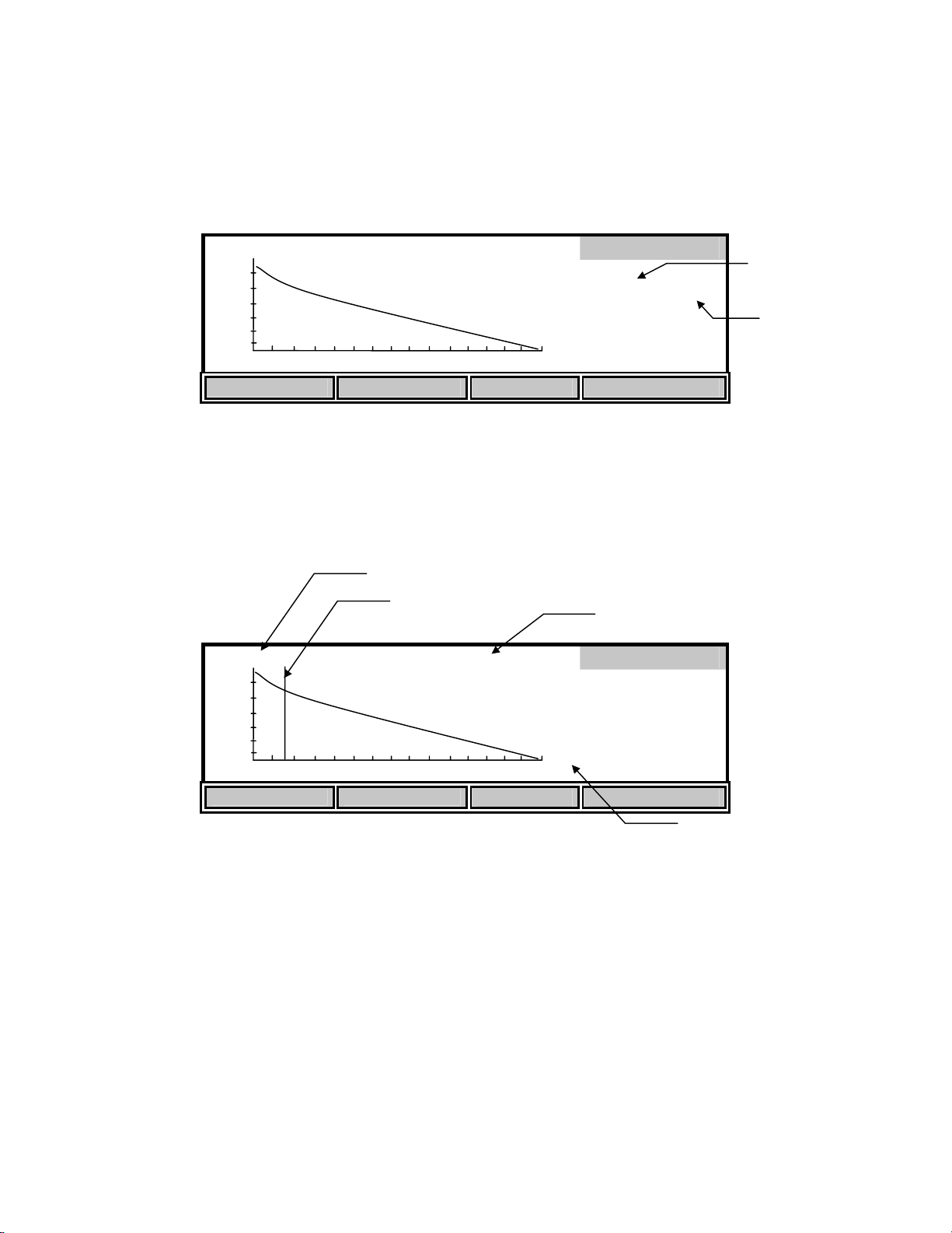
OUR
Time Reference
50.0 mg /L /hr 5.6 mg /L
mg
/L
0
DO (at Reference
MODIFY
REC:1 FULL
11:04 PM
870
09/21/98
! "
SETTINGS
Test time
Press the ! or " soft-keys to move the start time reference point to an optimal place on the
curve. The reference point is represented by a vertical line. Only data to the right of the
reference point will be used to calculate the OUR value. Moving this reference point allows you
to start the test at anytime and trim off unwanted data after the test has run. The DO reading at
the reference point is shown at the top. The reference point cannot move closer than the
minimum time to the end of the test.
The [SETTINGS] soft-key allows you to modify or input values for the Dilution factor. Changes
to the Dilution factor are saved if you save the record again.
36
Page 40
SOUR
The 5100 uses the following formula to calculate the SOUR value:
OUR =
DO
T
START
ELAPSED
- DO
END
3600 Sec
x
1 Hour
Total Volume
x
Sample Volume
=
mg/L/h
Where:
DO
DO
T
ELAPSED
Total Volume
= Dissolved oxygen level at start of test
START
= Dissolved oxygen level at end of test
END
= Elapsed time of test in seconds
= Dilution factor of sample (entered in setup screen as Sample/Total)
Sample Volume
SOUR =
OUR
Solids Weight
mg/h/g (mg O
=
/ hour / g solids)
2
Where:
Solids Weight = Total Solids or Volatile Suspended Solids in g/L
From the Model 5100 Application mode menu press the [SOUR] (Specific Oxygen Uptake Rate)
soft-key. The following screen will be displayed.
SOUR
mg
2.8
25.37°C 9.12 0:00
START SETUP REVIEW SEND
/h /g
SEND: off
mg
/L
37
Page 41
[
[
[*]
[
[
[
Press [SETUP] to change the SOUR parameters. The following screen shows the default
parameters.
Sample / Total 1 / [ 1]
Min. Time
Max. Time
Min. Beginning DO
Min. Ending DO
Solids Weight
UP DOWN DIGIT NEXT
1] min.
15] min.
5.00] mg/L SEND: off
2.00] mg/L
1.000] g/L
SOUR
SOUR@20
Use the [UP], [DOWN], [DIGIT] and [NEXT] soft-keys to change the following parameters as
necessary:
Sample / Total: Enter the ratio of sample volume to total volume. For example, if
you are diluting 1 to 10 (1 part sample plus
9 parts dilution water)
then enter the number 10. This would be a 10-fold dilution.
Min. Time: Enter the minimum time (in minutes).
Max. Time: Enter the maximum time (in minutes). When the maximum time is
reached, the test will end.
Min. Beginning DO: Enter the minimum level of DO allowed at the start of the test. If the
DO falls below this level, the test will not start.
Min. Ending DO: Enter the minimum level of DO allowed during the test. If the DO
level falls to this value, the test will end.
Solids Weight: Enter the Total Solids or Volatile Suspended Solids concentration of
the sample in g/L. The maximum acceptable value is 31.999 g/L.
SOUR@20: This applies the calculation for temperature correction to 20°C
according to the Farrell and Bhide equation as follows:
SOUR
= SOURT x Θ
20
(20-T)
Where:
Θ = 1.05 above 20°C
1.07 below 20°C
This calculation is only valid for temperature ranges from 10° - 30°C
SEND: on/off This sets the RS232 status at the beginning of the test.
After the parameters have been set, press [ENTER] to save them and return to the SOUR menu.
38
Page 42

SOUR
mg
7.7
25.35°C 8.09 0:00
SOUR SETTING SAVED
START SETUP REVIEW SEND
Once the parameters have been set, you are ready to begin. Place the probe in the prepared
sample and make certain no air bubbles are trapped, then turn on the stirring and wait a few
seconds for the temperature readings to stabilize.
NOTE: It is normal for the SOUR reading to oscillate for the first few seconds.
Press [START] to begin the SOUR measurement. The following screen shows the available softkeys .
40.7
25.35°C 6.57 1:09
END SEND ON
/h /g
mg
/h /g
SOUR
mg
/L
mg
/L
@20
SEND: off
Current DO
SOUR
SEND: off
RS232 status
RS232 status
The SOUR value is displayed on the screen and is updated approximately once per second.
The [SEND ON/OFF] soft-key toggles the RS232 status. Press [SEND ON] if you want to send
the readings to a computer or serial printer during the SOUR measurement. The RS232 status is
displayed just above the elapsed time. During the SOUR measurement, data will be sent every 15
seconds until the SOUR measurement ends or the [SEND OFF] soft-key is pressed. The
following is an example of the format:
NOTE: Once pressed, the [SEND ON] soft-key toggles and becomes a [SEND OFF] soft-key.
Second mg/h/g C mg/L 10:32:36 09/21/98
1 .36 25.35 7.35
15 92.57 25.35 6.99
30 64.55 25.34 6.83
45 42.54 25.35 6.71
60 45.76 25.35 6.60 . . .
39
Page 43

If you want to stop the SOUR measurement before the maximum time or minimum ending DO
(entered in SOUR setup) is reached, press the [END] soft-key. The final SOUR reading will be
displayed on the screen.
mg
20.07
/h /g
25.33°C 1.29 11:38
PROCESS COMPLETE
START SETUP STORE SEND
NOTE: The DO and temperature readings do not stop updating on the screen.
After the SOUR measurement has ended, the [SEND] soft-key can be used to send all of the DO
values and the final SOUR to a computer or serial printer via the RS232 port. The format is as
follows:
Time stamp: 10:32 AM
Date stamp: 09/21/98
@20
mg
/L
SOUR
SEND on
Reference point: 30 (sec.)
Second mg/L
1 7.35
15 6.99
30 6.83
45 6.71
60 6.60 . . .
701 1.98
SOUR = 26.04 mg/h/g
SOUR@20 = 20.07 mg/h/g Tavg = 25.34 C
Dilution ratio: 1 / 1(Sample/Total)
Solids Weight : 1.000 g/L
NOTE: If you have run a SOUR measurement, but did not enter the appropriate sample dilution,
you will get uncorrected results. However, after running the SOUR measurement, you
may return to the SOUR setup screen, change the Sample / Total ratio or Solids Weight,
then press [ENTER] to save the changes. The recalculated SOUR value will be
displayed. Press [SEND] to send the new SOUR value to a computer or serial printer via
the RS232 port.
If you want to save these values press the [STORE] soft-key. A record number will then show
up under the REVIEW menu. If the record slot contains a set of data, an indicator saying FULL
will appear beside the test number. If the record slot does not contain a set of data, the indicator
will say EMPTY.
SOUR@20 Indicator
40
Page 44

20.1 mg /h /g @20 6.8 mg /L
mg
/L
0
NEXT REC. MODIFY SAVE SEND
705
REVIEW
REC:1 EMPTY
10:32 AM
09/21/98
Record Number
FULL or EMPTY
indicator
Press the [NEXT REC.] soft-key to change the record number to find an empty slot, or pick a slot
to overwrite (you cannot delete results, you must overwrite). Press the [SAVE] soft-key to save
the current test data into that slot. Once you have saved the data you can press the [MODIFY]
soft-key to change the parameters of the test.
20.1 mg /h /g @20 6.8 mg /L
mg
/L
0
SOUR
Time Reference
DO (at Reference
MODIFY
REC:1 FULL
10:32 AM
705
09/21/98
! "
SETTINGS
Test time
Press the ! or " soft-keys to move the start time reference point to an optimal place on the
curve. The reference point is represented by a vertical line. Only data to the right of the
reference point will be used to calculate the SOUR value. Moving this reference point allows
you to start the test at anytime and trim off unwanted data after the test has run. The DO reading
at the reference point is shown at the top. The reference point cannot move closer than the
minimum time to the end of the test.
The [SETTINGS] soft-key allows you to modify or input values for the Dilution factor and
Solids Weight. These changes are saved if you save the record again.
41
Page 45

Remote
From the Model 5000/5100 Application mode menu press the [REMOTE] soft-key. The
following screen will be displayed.
STIR
ON
SKIP UP DOWN CONFIRM
ID: 1680 MODE :0
96.4% 24.94 C
REMOTE
The Remote mode is used in conjunction with YSI 5910 BOD Analyst software to greatly reduce
the labor required for processing BODs and calculating BOD values.
Remote mode is also used to control the 5000/5100 via computer. This can be done using any
standard communications program. See Appendix D - Remote Command Language for details.
RS232 Serial Port
The RS232 serial port uses a standard DB9 connector. Use a straight serial cable (not a null
modem) to connect the 5000/5100 to a computer serial port or a serial printer. See
15. Accessories and Replacement Parts for the YSI item number. A 9 to 25 pin adapter will also
be needed if the computer has a 25 pin serial port. Port settings are 9600 baud, 8 bits, Parity
None, Stop bits 1, and Flow Control set to Xon / Xoff.
Bar Code Reader
The YSI Model 5015 bar code reader may be connected to the Model 5100 while in the Remote
mode. This greatly improves data entry when entering sample ID numbers used with YSI BOD
Analyst software. The YSI 5015 has a 6-Pin Mini DIN connector that connects to the rear of the
5100 (see section 4.3 for the location of the socket). The model 5000 does not support a bar code
reader. Before using the 5015 bar code reader for the first time, it must be programmed as
follows:
1. Plug the bar code reader into the connector labeled “BAR CODE” on the rear of the 5100.
2. Turn on the 5100.
The YSI 5015 bar code reader may be either an Imageteam 3800/3900 or Laser Wedge 300 scanner.
**Please check which scanner you have by locating the scanner’s operations manual. If your Bar Code
Scanner is an Imageteam 3800/3900 then you will follow the first set of instructions to initialize.
Follow the second set of instructions if you have a Laser Wedge 300 scanner.
A) Imageteam 3800/3900 scanner
The following instructions involve the IMAGETEAM 3800/3900 User’s Guide:
42
Page 46

1. Prepare the scanner by installing the ferrite bead on the scanner’s cable near to where it plugs
into the 5100 meter as shown in the following diagram:
2. Turn to page 1-7 and scan the “Keyboard Wedge Interface for IBM PC AT and compatibles”
bar code label. The scanner should beep, indicating that it is ready to be used.
3. Test the bar code reader configuration by selecting Remote mode from the Application menu
of the 5100 and scanning a BOD bottle label. The bar code reader and 5100 meter will beep
and the 5100 will briefly display ”BC” along with the bar code number.
B) Laser Wedge 300 scanner
The following instructions involve the Laser Wedge 300 Bar Code Reader Programming Menus
booklet:
1. Turn to the page entitled “Bar Codes For Menus”, the last page in the booklet. Fold out the
page so that the list of bar codes is scanable. Keep this page unfolded for later use as it
contains the numbers and letters that will be used to program the bar code reader in the
following steps.
2. Turn to the page entitled “Status Check”, the second to last page. Scan the DEFAULT ALL
PARAMETERS bar code to load the factory default parameters. The bar code reader will
beep to indicate a successful scan.
43
Page 47

3. Turn to the page entitled “Terminal Selection”, the first page in the booklet.
3.1. Scan the ENTER TERMINAL SELECTION bar code.
3.2. Scan the 0 code on the “Bar codes for menus” page that you unfolded earlier.
Hold the reader close to the page to prevent scanning more than one code at a
time.
3.3. Scan the 1 code on the “Bar codes for menus” page.
3.4. Go back to the “Terminal Selection” page and scan the EXIT TERMINAL
SELECTION bar code.
4. Turn to the page entitled “General III Control Parameters”, the sixth page in the booklet.
4.1. Scan the ENTER GENERAL III SELECTIONS bar code.
4.2. Scan the POSTAMBLE bar code.
4.3. Scan the 0 code on the “Bar codes for menus” page that you unfolded earlier.
4.4. Scan the D code.
4.5. Scan the 0 code again.
4.6. Scan the A code.
4.7. Go back to the “General III Control Parameters” page and scan the EXIT
GENERAL III SELECTIONS bar code.
5. Test the bar code reader configuration by selecting Remote mode from the Application menu
of the 5100 and scanning a BOD bottle label. The bar code reader should beep, the 5100
should beep (if the beeper is enabled) and the 5100 should briefly display ”BC” and the bar
code number.
External Computer Keyboard
An external computer keyboard may be connected to the Model 5100 while in the Remote mode.
This greatly improves data entry when entering sample ID numbers used with YSI BOD Analyst
software (when a bar code reader is not available). The computer keyboard must be PC
compatible and have a 6-Pin Mini DIN connector. A commercially available adapter may be used
if necessary (5-Pin DIN to 6-Pin mini DIN). See 4.3 Rear Panel for the location of the socket.
The model 5000 does not support an external computer keyboard.
8. Diagnostics
The YSI 5000/5100 has a diagnostic mode that is used primarily during troubleshooting. In
Diagnosis mode you can view information from specific sensors, such as DO probe current, DO
background current and pressure sensor offset. This information is useful when trying to isolate
problems or monitor sensor conditions. When the 5000/5100 senses a problem, it displays an
error code and message. Diagnosis mode can be used to determine when membrane/probe service
is needed, before the instrument displays an error code. Refer to section
44
Page 48
12. Troubleshooting for additional information on error codes.
From the Main mode, press the [CALIBRATE] soft-key to enter Calibration mode, then press the
[Diagnosis] soft-key to enter Diagnosis mode. The following screen will be displayed.
Diagnosis
HISTORY SENSOR HELP RESET Ps
History
Press the [HISTORY] soft-key to display the following information.
Date Time DO uA %/uA C
Diagnosis
02/01 14:12 16.8 5.98 21.9
02/02 08:42 16.3 7.90 28.0
02/05 09:55 17.0 6.42 23.0
02/06 10:58 17.1 7.47 27.9
02/07 13:08 16.9 6.43 22.8
HISTORY SENSOR HELP RESET Ps
The History screen displays information about the last five DO calibrations. This information is
useful for tracking the performance of the DO probe/membrane. The following parameters are
displayed:
Date: The date the calibration was performed.
Time: The time the calibration was performed.
DO uA: The dissolved oxygen calibration current in microamps. The calibration
current (100% saturation at sea level) of an ideal probe using a 1 mil
(standard) membrane is 13.7uA @ 20°C. If the probe current (100%
saturation @ 20°C, 1 mil membrane) is greater than 17.0uA or lower than
8.0uA, the membrane/probe may need service. See 12. Troubleshooting,
Error Codes, E3 and E4.
%/uA: The slope of the dissolved oxygen probe in percent per microamp
corrected to 20°C. The slope of an ideal probe using a 1 mil membrane is
45
Page 49

7.3 %/uA @ 20°C. If the probe slope (1 mil membrane) is greater than
12.6 %/uA or lower than 5.9 %/uA, the membrane/probe may need
service. See 12. Troubleshooting, Error Codes, E3 and E4.
C: The temperature at the time of calibration in °C.
Sensor
Press the [SENSOR] soft-key to display the following sensor diagnostics screen:
System Parameters
Sensor
Cal. Temperature = 22.85 C
Probe Slope = 6.43 %/uA @20C
Probe Offset = 0.000 uA
Probe Current = 16.91 uA
Pressure Offset = 830 mbar P = 981
Cal. Temperature: The temperature at the time of the last calibration in °C.
Probe Slope: The slope of the dissolved oxygen probe in percent per microamp
corrected to 20°C. The slope of an ideal probe using a 1 mil
membrane is 7.3%/uA @ 20°C. If the probe slope (1 mil
membrane) is greater than 12.6 %/uA or lower than 5.9 %/uA, the
membrane/probe may need service. See 12. Troubleshooting, Error
Codes, E3 and E4.
Probe Offset: The zero offset current (background current) of the DO probe in
microamps. The factory default value is 0.000 uA. This value will
only change after a zero calibration is performed (see 6.2 Zero
Calibration). If this value is greater than 0.15uA (after a zero
calibration) the membrane/probe may need service. See 12.
Troubleshooting, Error Code E2.
Probe Current: The present (real time) DO probe current in microamps.
Pressure Offset: The offset of the barometer in millibars. This value will change
whenever the barometer is calibrated. The normal range is 300 to
1300 mbar.
P: Current barometer reading in millibars.
Press [MODE] to return to the Diagnosis menu. Press [MODE] two more times to return to the
Main menu.
46
Page 50
Reset Ps
The [RESET Ps] soft-key (Reset Parameters) is used to reset all instrument parameters to the
factory default values. This is useful when the parameters have been changed or corrupted, such
as when new software is loaded. Press the [RESET Ps] soft-key to display the following:
Reset
Press ENTER to RESET Parameters
HISTORY SENSOR HELP RESET Ps
Press [ENTER] to confirm. All parameters, including calibration values, will be reset. If you do
NOT wish to reset the parameters, press [MODE], instead of [ENTER], to return to the
Diagnosis menu.
WARNING: Resetting the instrument parameters to the factory default values will clear
the barometer calibration/setting. You MUST recalibrate the barometer before performing
an autocal. See 6.1 Dissolved Oxygen Calibration Barometer.
47
Page 51

9. Princip l es o f Operation
YSI dissolved oxygen probes use membrane-covered, Clark-type polarographic sensors with
built-in thermistors for temperature measurement and compensation. A thin permeable
membrane, stretched over the sensor, isolates the sensor elements from the environment, but
allows oxygen and certain other gases to enter. When a polarizing voltage is applied across the
sensor, oxygen that has passed through the membrane reacts at the cathode, causing a current to
flow. This current is read and interpreted by the YSI dissolved oxygen meter utilizing customized
electronics and software to assure the highest possible accuracy and reliability.
Oxygen diffuses through the membrane at a rate proportional to the pressure difference across it.
Since oxygen is rapidly consumed at the cathode, it can be assumed that the oxygen pressure
inside the membrane is zero. Hence, the amount of oxygen diffusing through the membrane is
proportional to the absolute pressure of oxygen outside the membrane. If the oxygen pressure
increases, more oxygen diffuses through the membrane and more current flows through the
sensor. A lower pressure results in less current.
48
Page 52

10. Understanding Dissolved Oxygen Error Factors
The major sources of error in DO measurement are the accuracy of the instrument components,
the accuracy of the probe, and the user’s ability to calibrate the system precisely. Most errors can
be reduced substantially by calibrating at DO levels and probe temperatures as close as possible
to the expected measurement DO levels and temperatures.
In the following, individual sources of error and their ranges are listed. By calculating the rootmean-squared sum of these individual uncertainties (usually less than half the possible error), the
user can estimate the probable error in any reading.
Note that all types of errors discussed are not necessarily present in a given situation. If salinity
compensation is not used, for example, no salinity compensation error need be considered. If
calibration is to a Winkler Titration sample, calibration errors are replaced by the Winkler
uncertainty.
Type 1 Errors: Instrument Components
a. Instrument accuracy:
±0.1% plus 1 least significant digit.
Type 2 Errors: Probe Accuracy
a. Probe background current error:
background factor x (1 - a/b)c
where a is the observed calibration value, b is the solubility of oxygen in fresh water at 760 mm
Hg and at measurement temperature, and c is the measured DO value.
a, b and c are all measured in mg/L or all are measured in % air saturation.
Use the following table to determine the background factor:
probe temp. in °C background factor (%)
0 2.3
10 1.5
20 1.0
30 0.8
40 0.6
b. Probe nonlinearity error:
±0.3% of reading
49
Page 53

c. Temperature compensation error: The variation from nominal response to sample temperature
is ±0.2% of the DO reading per degree C of the temperature difference between the
temperature of the sample and the temperature at which the probe was calibrated.
Type 3 Errors: Calibration
a. Sample temperature uncertainty error:
±1% of reading
This error is approximately zero when using AUTO CAL, when manually calibrating in the % air
saturation mode or when calibrating to a Winkler titration sample.
b. Error due to barometric pressure uncertainty of 9 mmHg (12 mbar):
±1.2% of reading
c. Error due to altitude estimation uncertainty of 500 ft (152m):
±1.8% of reading
This error is near zero when using AUTO CAL.
Error Calculation Example
The example given assumes that air calibration is used. If the Winkler titration calibration
method is used, type 3 errors are replaced by the uncertainty attributable to the overall Winkler
determination. This example is for an extreme combination of conditions.
Calibration conditions:
method: air calibration
temperature: 24°C
altitude: 600 feet (183 meters)
calibrated to: 8.24 mg/L
Measurement conditions:
temperature: 20°C
reading: 7.26 mg/L
mode: mg/L
50
Page 54

Calculation
Type Description Calculation Error (mg/L)
1a instrument accuracy (±0.001 x 7.26) + 0.01 ±0.017
2a probe background ±0.01 x (1- (8.24/9.09)) x 7.26 ±0.007
2b probe nonlinearity ±0.003 x 7.26 ±0.021
2c temp. compensation ±(24-20) x 0.002 x 7.26 ±0.058
3a temp. uncertainty ±0.01 x 7.26 ±0.073
3b pressure ±0.012 x 7.26 ±0.087
Probable error can be determined by an r.m.s. calculation:
r.m.s. error = [.0172 + .0072 + .0212 + .0582 + .0732 + .0872 ]
1/2
= ±0.13 mg/L
51
Page 55
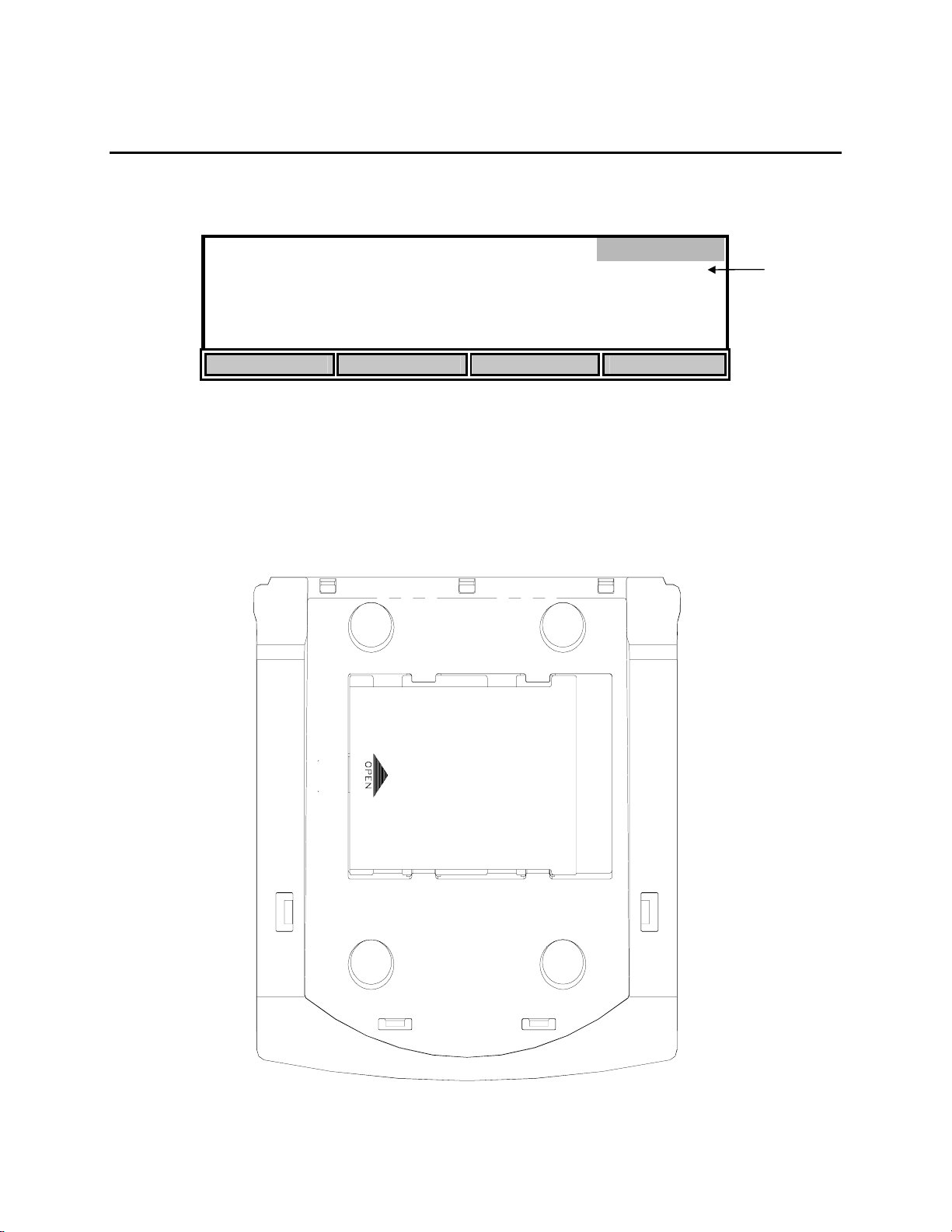
11. Maintenance
Batteries
Low batteries are indicated on the display by “LOW BATT” as shown here.
Main
LOW BATT
8.20*
mg
/L
24.38°C 11:33AM
STORE REVIEW SEND CALIBRATE
When this happens, replace the batteries with 4 fresh alkaline C-size batteries as soon as
possible.
• Turn off the instrument.
Low battery
warning
• Turn the instrument over and slide the battery cover to the right (as indicated on the cover)
and remove it.
52
Page 56
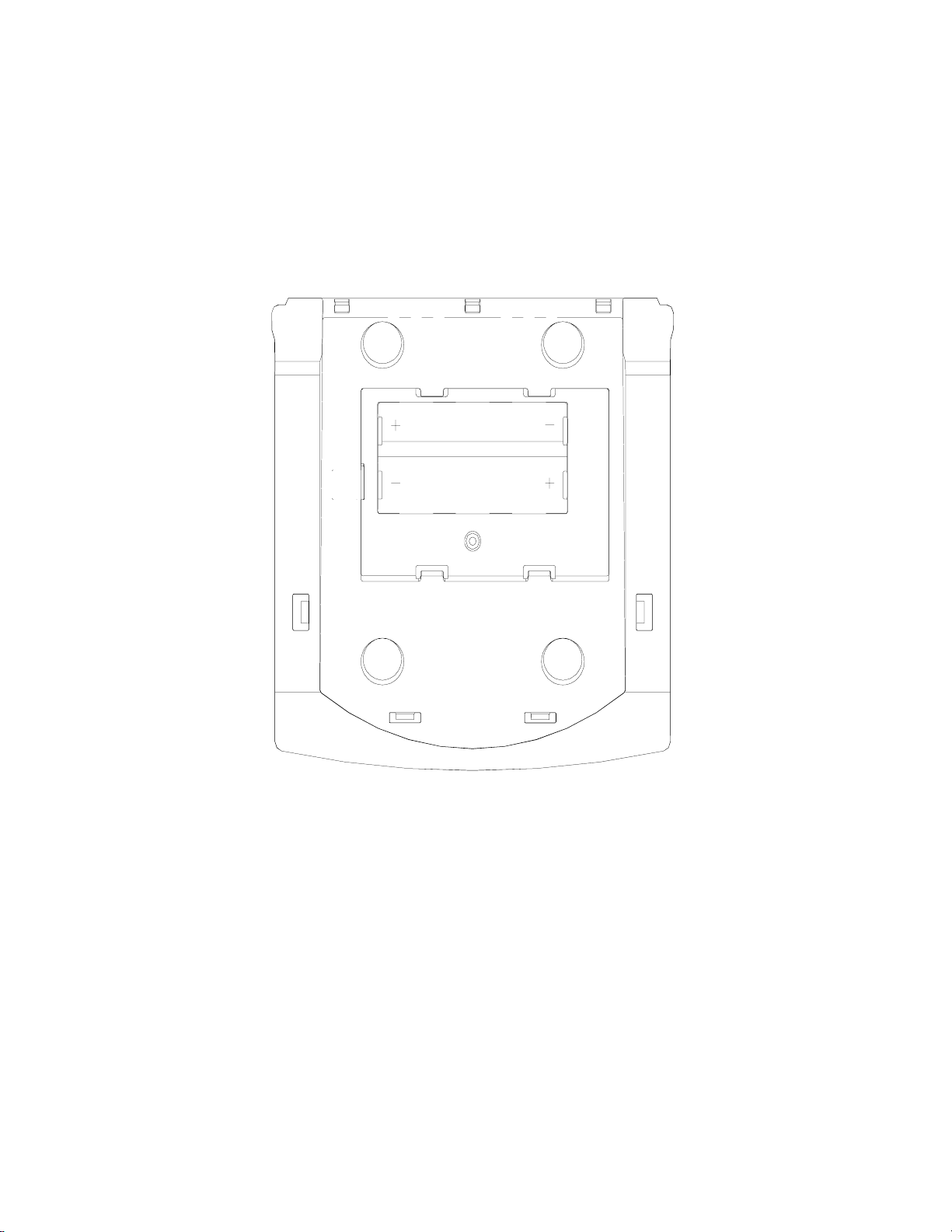
• Remove the old batteries and install fresh alkaline batteries. NOTE: Always observe the
correct polarity when installing the batteries.
• Replace the battery cover and slide it to the left to lock it into place.
NOTE: The instrument parameters are stored in nonvolatile memory and will not be lost during
battery replacement.
53
Page 57

12. Troubleshooting
Error Messages
The instrument performs a Power On Self Test each time it is turned on. The following error
codes are provided to facilitate troubleshooting.
Code/Problem Error Possible Cause Correction
Blank Display Dead/low batteries Replace batteries or
connect power supply
E1: Check Probe
Intermittent connection
Temperature over
E2: Check
Membrane
Incorrect probe zeroing
Probe needs servicing See probe instructions
Probe malfunction Repair or replace
5011 adapter
improperly connected
Temperature under
range
range
Faulty temperature
High Background
current (DO)
Connector improperly
installed
in cable or plug
Electrical leakage in
connector or cable
sensor
Insufficient warm-up
time
procedure
Unplug 5011 from
power supply connector
Check probe
connection
Repair or replace
Repair or replace
Repair or replace
See Calibration
See Zero Calibration
E3: Check
Membrane
Contaminated
Membrane too thick Try another membrane
High resistance in
DO Low current Insufficient electrolyte See probe instructions
See probe instructions
electrodes or fouled
membrane
Repair or replace
probe connection
54
Page 58

Code/Problem Error Possible Cause Correction
E4: Check
DO High Current Membrane too thin Try another membrane
Membrane
Electrodes need
Repair or replace
resurfacing
Internal leakage in
Repair or replace
probe or cable
connector
Short circuit in probe or
Repair or replace
cable
E5: Check
DO unstable Membrane damaged Replace membrane
Membrane
Probe needs servicing See probe instructions
Connector improperly
Check probe connection
installed
Intermittent connection
Repair or replace
in cable or plug
Probe malfunction Repair or replace
ERROR: DO reading < min. DO The DO reading at the start of the OUR or SOUR
measurement is below the “minimum beginning
DO” entered in the OUR or SOUR setup.
See 7.2 Application Mode, OUR, or SOUR.
ERROR: Illegal value The value entered is
Enter the correct value
outside the acceptable
range.
ERROR: RTC defect control
Real time clock failure Return for repair
register
ERROR: Init. Logger failed Logger initialization
Return for repair
failed
55
Page 59

13. Warranty & Repair
YSI 5000 Series Dissolved Oxygen Instruments are warranted for two years from date of purchase by the end user
against defects in materials and workmanship. YSI dissolved oxygen probes and cables are warranted for one year
from date of purchase by the end user against defects in material and workmanship. Within the warranty period, YSI
will repair or replace, at its sole discretion, free of charge, any product that YSI determines to be covered by this
warranty.
To exercise this warranty, write or call your local YSI representative, or contact YSI Customer Service in Yellow
Springs, Ohio. Send the product and proof of purchase, transportation prepaid, to the Authorized Service Center
selected by YSI. Repair or replacement will be made and the product returned, transportation prepaid. Repaired or
replaced products are warranted for the balance of the original warranty period, or at least 90 days from date of repair
or replacement.
Limitation of Warranty
This Warranty does not apply to any YSI product damage or failure caused by (i) failure to install, operate or use the
product in accordance with YSI’s written instructions, (ii) abuse or misuse of the product, (iii) failure to maintain the
product in accordance with YSI’s written instructions or standard industry procedure, (iv) any improper repairs to the
product, (v) use by you of defective or improper components or parts in servicing or repairing the product, or (vi)
modification of the product in any way not expressly authorized by YSI.
THIS WARRANTY IS IN LIEU OF ALL OTHER WARRANTIES, EXPRESSED OR IMPLIED,
INCLUDING ANY WARRANTY OF MERCHANTABILITY OR FITNESS FOR A PARTICULAR
PURPOSE. YSI’s LIABILITY UNDER THIS WARRANTY IS LIMITED TO REPAIR OR
REPLACEMENT OF THE PRODUCT, AND THIS SHALL BE YOUR SOLE AND EXCLUSIVE
REMEDY FOR ANY DEFECTIVE PRODUCT COVERED BY THIS WARRANTY. IN NO EVENT
SHALL YSI BE LIABLE FOR ANY SPECIAL, INDIRECT, INCIDENTAL OR CONSEQUENTIAL
DAMAGES RESULTING FROM ANY DEFECTIVE PRODUCT COVERED BY THIS WARRANTY.
YSI Factory Service Centers
United States
YSI Incorporated • Repair Center • 1725 Brannum Lane • Yellow Springs, OH • 45387 • Phone: 937 767-7241 • Fax: 937 767-9353
Endeco/YSI Inc. • 13 Atlantis Drive • Marion, MA • 02738 • Phone: 508 748-0366 • Fax: 508 748-2543
Europe
YSI LTD • Lynchford House • Lynchford Lane • Farnborough, Hampshire • GU14 GLT • Phone: 441 252 514711 • Fax: 441 252 511855
YSI Authorized Service Centers
California
EviroServices & Repair • 1110 Burnett Avenue, Suite D • Concord, CA • 94520 • Phone: 510 609-1088 • Fax: 510 674-8655
Fisher Scientific ISD • 2822 Walnut Avenue, Suite E • Tustin, CA • 92681 • Phone: 800 395-5442
Florida
Aquatic Eco Systems, Inc. • 1767 Benbow Court • Apopka, FL • 32703 • Phone: 407 886-3939 • Fax: 407 886-6787
Georgia
Fisher Scientific ISD • 2775 Horizon Ridge Court • Suwanee, GA • 30174 • Phone: 800 395-5442
Illinois
Fisher • 1600 West Gleenlake Avenue • Itasca, Ill • 60143 • Phone: 800 395-5442
Maine
Q. C. Services • P.O. Box 68 • Harrison, ME • 04040 • Phone: 207 583-2980
Mississippi
Aquacenter • 166 Seven Oaks Road • Leland, MS • 38756 • Phone: 601 378-2861 • Fax: 601 378-2862
New Jersey
Fisher Scientific ISD • 52 Fadem Road • Springfield, NJ • 07081 • Phone: 800 395-5442
Oregon
Q. C. Services • P.O. Box 14831 • Portland, OR • 97293 • Phone: 503 236-2712
Pennsylvania
Fisher Scientific ISD • 585 Alpa Drive • Blawnox, PA • 15238 • Phone: 800 395-5442
56
Page 60

Cleaning Instructions
NOTE: Before they can be serviced, equipment exposed to biological, radioactive, or toxic
materials must be cleaned and disinfected. Biological contamination is presumed for any
instrument, probe, or other device that has been used with body fluids or tissues, or with waste
water. Radioactive contamination is presumed for any instrument, probe or other device that has
been used near any radioactive source.
If an instrument, probe, or other part is returned or presented for service without a Cleaning
Certificate, and if in our opinion it represents a potential biological or radioactive hazard, our
service personnel reserve the right to withhold service until appropriate cleaning,
decontamination, and certification has been completed. We will contact the sender for
instructions as to the disposition of the equipment. Disposition costs will be the responsibility of
the sender.
When service is required, either at the user's facility or at YSI, the following steps must be taken
to insure the safety of our service personnel.
1. In a manner appropriate to each device, decontaminate all exposed surfaces, including any
containers. 70% isopropyl alcohol or a solution of 1/4 cup bleach to 1 gallon tap water are
suitable for most disinfecting. Instruments used with waste water may be disinfected with
.5% Lysol if this is more convenient to the user.
2. The user shall take normal precautions to prevent radioactive contamination and must use
appropriate decontamination procedures should exposure occur.
3. If exposure has occurred, the customer must certify that decontamination has been
accomplished and that no radioactivity is detectable by survey equipment.
4. Any product being returned to the YSI Repair Center, should be packed securely to prevent
damage.
5. Cleaning must be completed and certified on any product before returning it to YSI.
57
Page 61

Packing Instructions
1. Clean and decontaminate items to insure the safety of the handler.
2. Complete and include the Cleaning Certificate.
3. Place the product in a plastic bag to keep out dirt and packing material.
4. Use a large carton, preferably the original, and surround the product completely with packing
material.
5. Insure for the replacement value of the product.
Cleaning Certificate
Organization _______________________________
Department ________________________________
Address ___________________________________
City ______________ State _____ Zip _________
Country__________________ Phone ___________
Model No. of Device _____Lot Number__________
Contaminant (if known) ______________________
Cleaning Agent(s) used ______________________
Radioactive Decontamination Certified?
(Answer only if there has been radioactive exposure)
___ Yes ___ No
Cleaning Certified By _________________________
Name Date
58
Page 62

14. Required Notice
This equipment generates and uses radio frequency energy and if not installed and used properly,
may cause interference to radio and television reception. There is no guarantee that interference
will not occur in a particular installation. If this equipment does cause interference to radio or
television reception, which can be determined by turning the equipment off and on, the user is
encouraged to try to correct the interference by one or more of the following measures:
• Reorient the receiving antenna
• Relocate the computer with respect to the receiver
• Move the computer away from the receiver
• Plug the computer into a different outlet so that the computer and receiver are on
different branch circuits.
If necessary, the user should consult the dealer or an experienced radio/television technician for
additional suggestions. The user may find the following booklet, prepared by the Federal
Communications Commission, helpful: "How to Identify and Resolve Radio-TV Interference
Problems." This booklet is available from the U.S. Government Printing Office, Washington,
D.C. 20402, Stock No. 0004-000-00345-4.
59
Page 63

15. Accessories and Replacement Parts
YSI Item # Description Model / Comments
005117 Power Supply, 115 VAC, 800 ma 5000, 5100
051051 Power Supply, 230 VAC, 500 ma 5000, 5100
050101 Overlay, Window, 5000 5000
051015 Overlay, Window, 5100 5100
051016 Overlay, Keypad 5000, 5100
051009 Window 5000, 5100
050048 Board Assy, PC, Main 5000
051055 Board Assy, PC, Main 5100
111021 Display Assy 5000, 5100
051023 Door, Battery 5000, 5100
111015* Case Assy, Upper 5000
111007* Case Assy, Upper 5100
111017 Case Assy, Lower, w/battery door 5000, 5100
051043 Foot, Rubber, Self-Stick 5000, 5100
051034 Terminal, Battery, Push-On 5000, 5100
032061 Gasket, Connector, Probe/Bar Code 5000, 5100 (2 required)
032063 Gasket, Connector, Power Supply 5000, 5100
032064 Gasket, Connector, RS232 5000, 5100
051025 Standoff, .25, Snap-In 5000, 5100 / Retain Display
003228* Extension, Switch 5000, 5100
051029 Operations Manual 5000, 5100
051042 Service Manual 5000, 5100
052021 RS232 Cable, DB9 5000, 5100
YSI Model 5015 Bar code reader 5100 only
YSI Model 5011 Probe adapter (converts from probe
MS connector to meter DIN)
* Instruments with serial numbers starting with 96L or lower, contact YSI.
60
5000, 5100
Page 64
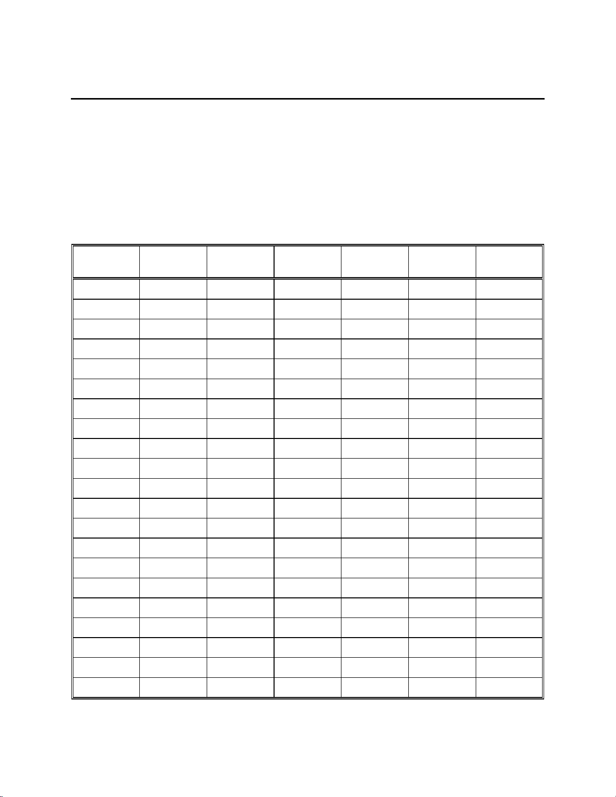
16. Appendix A - Oxygen Solubility Table
Solubility of Oxygen in mg/l in Water Exposed to Water-Saturated Air at 760
mm Hg Pressure as a function of temperature.
Salinity = Measure of quantity of dissolved salts in water.
Chlorinity = Measure of chloride content, by mass, of water.
0
/00) = 1.80655 x Chlorinity (0/
S(
00)
)
Temp
o
C
0.0 14.62 13.73 12.89 12.10 11.36 10.66
1.0 14.22 13.36 12.55 11.78 11.07 10.39
2.0 13.83 13.00 12.22 11.48 10.79 10.14
3.0 13.46 12.66 11.91 11.20 10.53 9.90
4.0 13.11 12.34 11.61 10.92 10.27 9.66
5.0 12.77 12.02 11.32 10.66 10.03 9.44
6.0 12.45 11.73 11.05 10.40 9.80 9.23
7.0 12.14 11.44 10.78 10.16 9.58 9.02
8.0 11.84 11.17 10.53 9.93 9.36 8.83
9.0 11.56 10.91 10.29 9.71 9.16 8.64
10.0 11.29 10.66 10.06 9.49 8.96 8.45
11.0 11.03 10.42 9.84 9.29 8.77 8.28
12.0 10.78 10.18 9.62 9.09 8.59 8.11
Chlorinity:0
Salinity:0
5.0 ppt
9.0 ppt
10.0 ppt
18.1 ppt
15.0 ppt
27.1 ppt
20.0 ppt
36.1 ppt
25.0 ppt
45.2 ppt
13.0 10.54 9.96 9.42 8.90 8.41 7.95
14.0 10.31 9.75 9.22 8.72 8.24 7.79
15.0 10.08 9.54 9.03 8.54 8.08 7.64
16.0 9.87 9.34 8.84 8.37 7.92 7.50
17.0 9.67 9.15 8.67 8.21 7.77 7.36
18.0 9.47 8.97 8.50 8.05 7.62 7.22
19.0 9.28 8.79 8.33 7.90 7.48 7.09
20.0 9.09 8.62 8.17 7.75 7.35 6.96
61
Page 65

Temp
o
C
21.0 8.92 8.46 8.02 7.61 7.21 6.84
22.0 8.74 8.30 7.87 7.47 7.09 6.72
23.0 8.58 8.14 7.73 7.34 6.96 6.61
24.0 8.42 7.99 7.59 7.21 6.84 6.50
25.0 8.26 7.85 7.46 7.08 6.72 6.39
26.0 8.11 7.71 7.33 6.96 6.62 6.28
27.0 7.97 7.58 7.20 6.85 6.51 6.18
28.0 7.83 7.44 7.08 6.73 6.40 6.09
29.0 7.69 7.32 6.96 6.62 6.30 5.99
30.0 7.56 7.19 6.85 6.51 6.20 5.90
31.0 7.43 7.07 6.73 6.41 6.10 5.81
32.0 7.31 6.96 6.62 6.31 6.01 5.72
33.0 7.18 6.84 6.52 6.21 5.91 5.63
Chlorinity:0
Salinity:0
5.0 ppt
9.0 ppt
10.0 ppt
18.1 ppt
15.0 ppt
27.1 ppt
20.0 ppt
36.1 ppt
25.0 ppt
45.2 ppt
34.0 7.07 6.73 6.42 6.11 5.82 5.55
35.0 6.95 6.62 6.31 6.02 5.73 5.46
36.0 6.84 3.52 6.22 5.93 5.65 5.38
37.0 6.73 6.42 6.12 5.84 5.56 5.31
38.0 6.62 6.32 6.03 5.75 5.48 5.23
39.0 6.52 6.22 5.98 5.66 5.40 5.15
40.0 6.41 6.12 5.84 5.58 5.32 5.08
41.0 6.31 6.03 5.75 5.49 5.24 5.01
42.0 6.21 5.93 5.67 5.41 5.17 4.93
43.0 6.12 5.84 5.58 5.33 5.09 4.86
44.0 6.02 5.75 5.50 5.25 5.02 4.79
45.0 5.93 5.67 5.41 5.17 4.94 4.72
62
Page 66

17. Appendix B - Pressures and Altitudes
Calibration Values for Various Atmospheric Pressures and Altitudes
PRESSURE ALTITUDE CALIBRATION
inches Hg mm Hg millibars Feet meters VALUE (%)
30.23 768 1023 -276 -84 101
29.92 760 1013 0 0 100
29.61 752 1003 278 85 99
29.33 745 993 558 170 98
29.02 737 983 841 256 97
28.74 730 973 1126 343 96
28.43 722 963 1413 431 95
28.11 714 952 1703 519 94
27.83 707 942 1995 608 93
27.52 699 932 2290 698 92
27.24 692 922 2587 789 91
26.93 684 912 2887 880 90
26.61 676 902 3190 972 89
26.34 669 892 3496 1066 88
26.02 661 882 3804 1160 87
25.75 654 871 4115 1254 86
25.43 646 861 4430 1350 85
25.12 638 851 4747 1447 84
24.84 631 841 5067 1544 83
24.53 623 831 5391 1643 82
24.25 616 821 5717 1743 81
23.94 608 811 6047 1843 80
23.62 600 800 6381 1945 79
23.35 593 790 6717 2047 78
23.03 585 780 7058 2151 77
22.76 578 770 7401 2256 76
22.44 570 760 7749 2362 75
22.13 562 750 8100 2469 74
21.85 555 740 8455 2577 73
21.54 547 730 8815 2687 72
21.26 540 719 9178 2797 71
20.94 532 709 9545 2909 70
20.63 524 699 9917 3023 69
20.35 517 689 10293 3137 68
20.04 509 679 10673 3253 67
19.76 502 669 11058 3371 66
63
Page 67
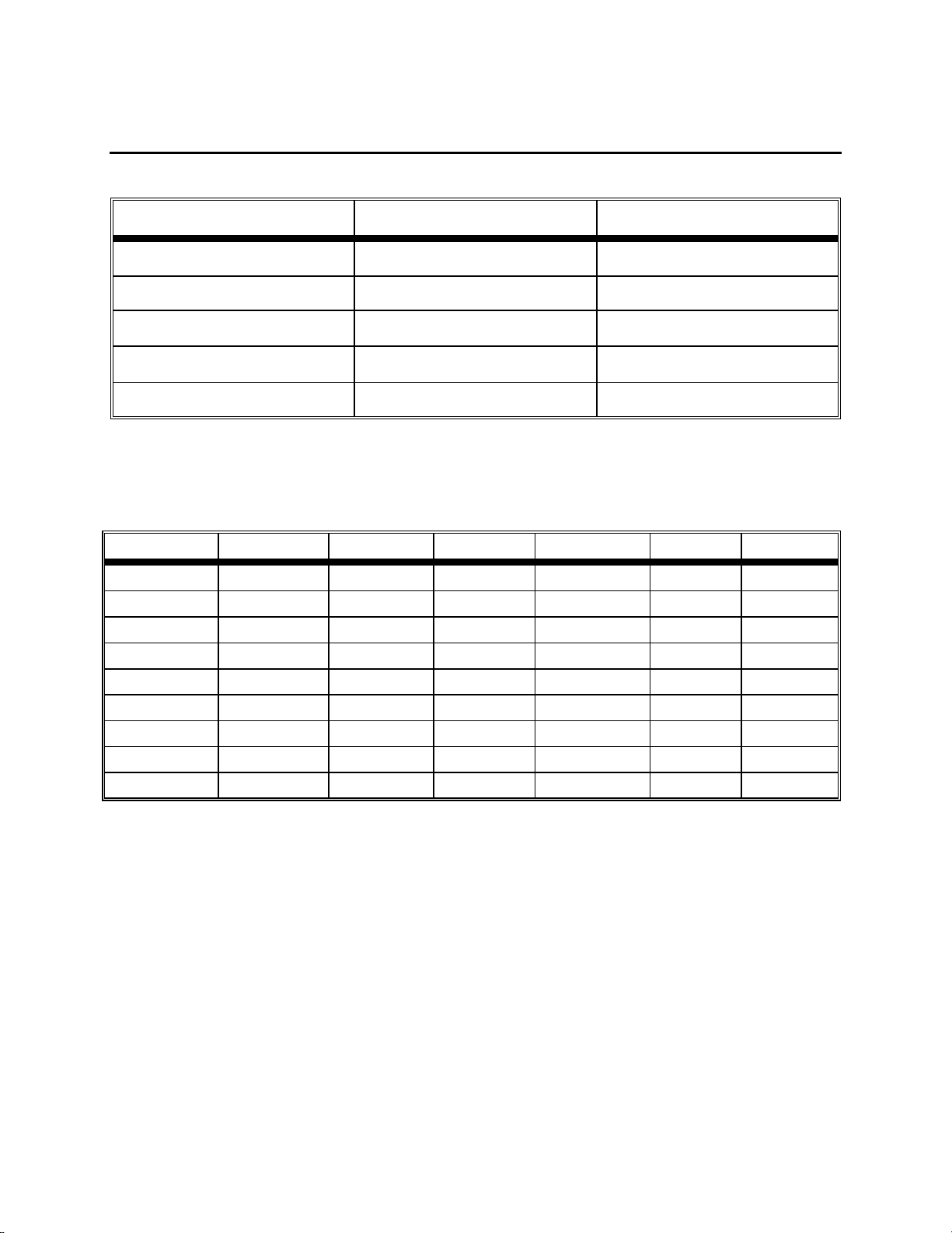
18. Appendix C - Conversion Factors
TO CONVERT FROM TO EQUATION
Feet Meters Multiply by 0.3048
Meters Feet Multiply by 3.2808399
Degrees Celsius Degrees Fahrenheit
Degrees Fahrenheit Degrees Celsius
9/5×(
5/9×(
o
C)+32
o
F-32)
Milligrams per liter (mg/l) Parts per million (ppm) Multiply by 1
Conversion Factors for Common Units of Pressure
kilo Pascals mm Hg millibars inches H20 PSI inches Hg
1 atm
1 kiloPascal
1 mmHg
1 millibar
1 inch H20
1 PSI
1 inch Hg
1 hectoPascal
1 cm H20
101.325 760.000 1013.25 406.795 14.6960 29.921
1.00000 7.50062 10.0000 4.01475 0.145038 0.2953
0.133322 1.00000 1.33322 0.535257 0.0193368 0.03937
0.100000 0.750062 1.00000 0.401475 0.0145038 0.02953
0.249081 1.86826 2.49081 1.00000 .0361 0.07355
6.89473 51.7148 68.9473 27.6807 1.00000 2.0360
3.38642 25.4002 33.8642 13.5956 0.49116 1.00000
0.100000 0.75006 1.00000 0.401475 0.0145038 0.02953
-7
0.09806 0.7355 9.8 x 10
0.3937 0.014223 0.02896
64
Page 68

19. Appendix D - Remote Command Language
Remote commands and data output are available only when the instrument is in the Remote
mode.
Command Format:
<Prefix><Command Type><Parameter><Suffix>
Prefix:
The prefix consists of the two character sequence <ESC>&. In HEX this is 1B 26.
Suffix:
The suffix consists of the two character sequence <CR><LF>. In HEX this is 0D 0A.
Command Types and Parameters:
Command types are arranged into two groups, immediate and automatic.
The Display command controls the display of remote messages.
Command type parameter description
D 0 string echoes the string to the first line of the display
D 1 string echoes the string to the second line of the display
D 2 none Clear display lines 0 and 1
D 3 0 Set display update flag line 0
D 3 1 Set display update flag line 1
The ouTput mode command controls how data flow is controlled. A bar code scan in T1 or T2
mode will cause a line of output, just as if the T command had been received.
Command type parameter description
T 0 none Continuous data output
T 1 none One line of data output in response
T 2 none One line after stable reading
65
Page 69
The P commands are for requesting system information.
Command type parameter description
P 0 none Request calibration parameters
P 1 none Request solubility table dump
P 2 none Request raw A/D
P 3 none Request System status
The system Setup commands.
Command type parameter description
S 0 nn.n set salinity to nn.n
S 1 hh:mm:ss set time of day, 24 hour clock
S 2 mm/dd/yy set calendar
S 4 1 emit an audio beep from beeper
S 5 0 DO. calibration and display mode is %
S 5 3 DO. calibration and display mode is mg/L
S 7 nnn.n Set DO. calibration value
S 9 0 Disable audio feedback
S 9 1 Enable audio feedback
Software Version requests:
Command type parameter description
V 0 none request software version
V 1 none request version date
V 2 none request model number
Reset command:
Command type parameter description
E none none reset system to defaults
66
Page 70

1725 Brannum Lane
Yellow Springs, Ohio 45387 USA 051029
937 767-7241 • 800 765-4974 • Fax 937 767-9353 A51029H
Info@ysi.com • www.YSI.com September 02
1998 YSI Incorporated
 Loading...