

Page 1
FDO 4410
FDO 4410W
OPERATING MANUAL
OPERATIONS MANUAL
ba76197e01 10/2017
FDO 4410
FDO 4410W
OPTICAL D.O. SENSOR
Page 2

FDO 4410
Contact YSI
1725 Brannum Lane
Yellow Springs, OH 45387 USA
Tel: +1 937-767-7241
800-765-4974
Email: environmental@ysi.com
Internet: www.ysi.com
Copyright © 2017 Xylem Inc.
2 ba76197e01 10/2017
Page 3

FDO 4410(W) Contents
FDO 4410(W) - Contents
1 Overview . . . . . . . . . . . . . . . . . . . . . . . . . . . . . . . . . . . . . . . 4
1.1 Structure and function . . . . . . . . . . . . . . . . . . . . . . . . . . . . 4
1.2 Recommended fields of application . . . . . . . . . . . . . . . . . 5
2 Commissioning, measuring . . . . . . . . . . . . . . . . . . . . . . . . 6
2.1 General information on the handling of the sensor cap . . 6
2.2 Commissioning . . . . . . . . . . . . . . . . . . . . . . . . . . . . . . . . . 6
2.3 Opening and closing the IDS plug connection (FDO 4410W)
7
2.4 Measuring . . . . . . . . . . . . . . . . . . . . . . . . . . . . . . . . . . . . . 8
2.5 Function check and user calibration . . . . . . . . . . . . . . . . . 8
2.6 Storage . . . . . . . . . . . . . . . . . . . . . . . . . . . . . . . . . . . . . . . 9
3 Maintenance, cleaning, replacement . . . . . . . . . . . . . . . . 10
3.1 General maintenance instructions . . . . . . . . . . . . . . . . . . 10
3.2 Exchanging the sensor cap . . . . . . . . . . . . . . . . . . . . . . . 11
3.3 Cleaning the sensor . . . . . . . . . . . . . . . . . . . . . . . . . . . . 12
3.4 Checking the zero point of the sensor . . . . . . . . . . . . . . . 13
4 What to do if... . . . . . . . . . . . . . . . . . . . . . . . . . . . . . . . . . 14
5 Technical data . . . . . . . . . . . . . . . . . . . . . . . . . . . . . . . . . 15
6 Wear parts and accessories . . . . . . . . . . . . . . . . . . . . . . . 18
Contact Information . . . . . . . . . . . . . . . . . . . . . . . . . . . . . 19
Ordering & Technical Support . . . . . . . . . . . . . . . . . . . . . 19
Service Information . . . . . . . . . . . . . . . . . . . . . . . . . . . . . 19
ba76197e01 10/2017
3
Page 4
Overview FDO 4410(W)
12
3
4
7
9
512811106
FDO 4410
FDO 4410W
1Overview
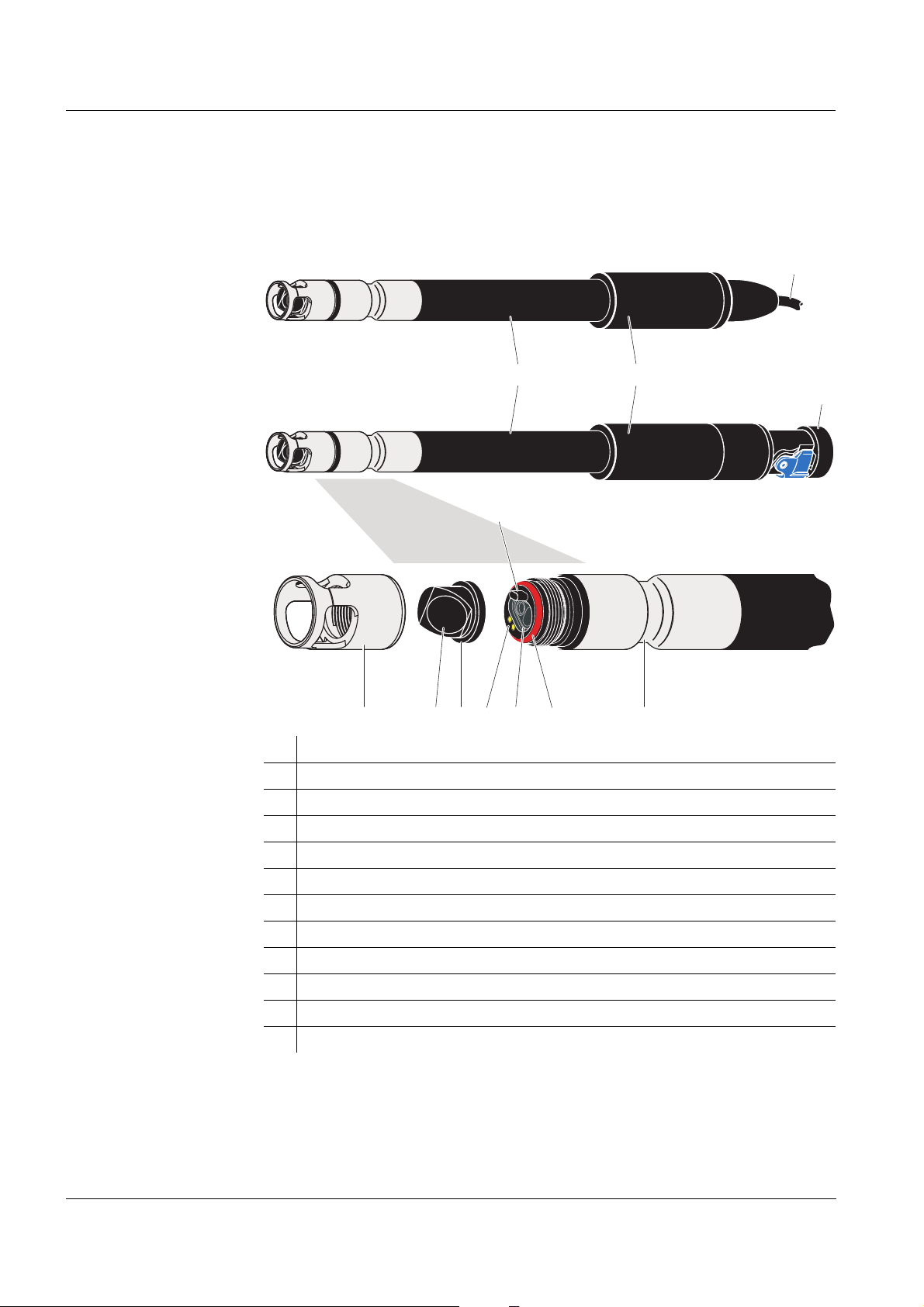
1.1 Structure and function
Structure
1 Shaft
2 Connecting head with active sensor electronics
3 Connection cable (FDO 4410)
4 IDS plug (FDO 4410W)
5 Protective hood
6 Sensor membrane
7 SC-FDO 4410 sensor cap with memory chip
8 Gold-plated contacts for the memory chip of the sensor cap
9 Locking device
10 Measurement window
11 O-ring
12 Thermistor enclosure with temperature sensor
4
ba76197e01 10/2017
Page 5

FDO 4410(W) Overview
Sensor cap with
memory chip
A memory chip is integrated in the sensor cap. The following data are stored
on the memory chip:
Type designation of the sensor cap
Series number
Data of the factory calibration or user calibration
Intelligent
membrane (IQMC
technology)
For each membrane, the individual calibration values are determined by
a factory calibration process and stored to the memory chip of the sensor
cap, ensuring maximum accuracy over the whole lifetime of the
sensor.
Automatic sensor
recognition
The data of the sensor and sensor cap is recalled by the meter when the
sensor is connected and is used for measurement and for measured value
documentation. The calibration data are stored in the sensor cap. Thus, the
calibration is automatically retained if the sensor or meter are exchanged.
The digital transmission technique guarantees the failure-free communication with the meter even with long connection cables.
Firmware update You can update the firmware of the IDS sensor using your meter.
Details on the firmware update are given in the current operating manual of
your meter.
Recommended
fields of
application
The current operating manual of your meter and the firmware update for the
sensor are available on the Internet under www.YSI.com.
1.2 Recommended fields of application
On site measurements in rivers, lakes and wastewater
Applications in water laboratories
BOD measurements
ba76197e01 10/2017
5
Page 6

Commissioning, measuring FDO 4410(W)
2 Commissioning, measuring
2.1 General information on the handling of the sensor cap
Despite its exterior robustness, the sensor is a high precision optical instrument. Therefore, you should take the following precautions when dealing with
the FDO 4410(W):
Please do not touch the sensor membrane with your fingers
Avoid any great mechanical stress of the sensor membrane (pressure,
scratches).
2.2 Commissioning
Scope of delivery D.O. sensor FDO 4410(W) with sensor cap
Check and storage vessel, FDO Check
Operating manual
Commissioning Connect the electrode to the meter.
FDO 4410 – via the sensor cable to a free IDS connec-
tor on the meter
FDO 4410W – via a connecting cable (accessory) to a
free IDS connector on the meter
or
– wireless via an IDS WA-S adapter (acces-
sory) to a WA-capable meter
Accessories for the connection of the FDO
4410W sensor to the meter: See chapter 6
W
EAR PARTS AND ACCESSORIES.
Opening and closing the IDS plug connection,
see section 2.3 O
IDS
PENING AND CLOSING THE
PLUG CONNECTION (FDO 4410W).
6
ba76197e01 10/2017
Page 7
FDO 4410(W) Commissioning, measuring
2
4
3
1
Plug connection
closed and locked
Guidance
Groove
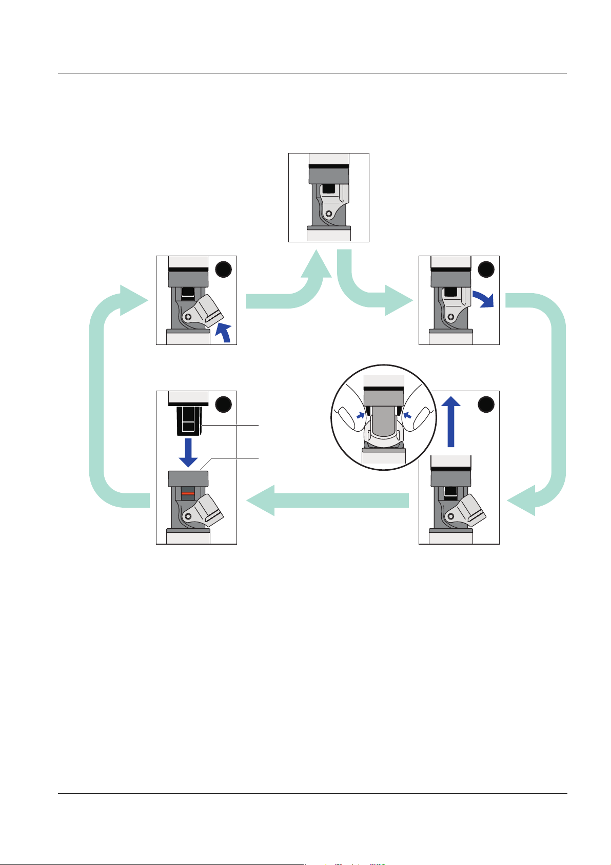
2.3 Opening and closing the IDS plug connection (FDO 4410W)
This section only applies to the IDS plug variant, FDO 4410W.
Opening the plug
connection
Closing the plug
connection
If necessary, clean the plug connection
Open the locking device (step 1)
Use your thumb and index finger to press the clips of the connector
together, and pull the connector out of the plug (step 2).
Make sure that the plug connection is completely dry and clean.
Align the guidance of the connector with the groove in the plug and insert
the connector in the unlocked plug until it catches (step 3).
Close the locking device (step 4).
ba76197e01 10/2017
7
Page 8

Commissioning, measuring FDO 4410(W)
12
2.4 Measuring
Minimum depth of
immersion
Observe the required minimum immersion depth (see chapter 5 TECHNICAL
DATA).
Incident flow The FDO 4410(W) D.O. sensor enables precise measurements without any
incident flow.
However, an incident flow of the sensor membrane improves the responding
behavior of the sensor (see chapter 5 T
ECHNICAL DATA). The incident flow can
be provided in different ways, e. g.:
The flow of the water to be measured is sufficient (aeration tank, water
pipe, stream)
Slowly pull the sensor through the water by hand (lake, container), or
Use a flow aid such as a magnetic stirrer with stirring device (see
chapter 6 W
EAR PARTS AND ACCESSORIES)
2.5 Function check and user calibration
Factory calibration The FDO 4410(W) is factory calibrated. In the recommended application (see
page 5), the measuring characteristics of the sensor cap remain stable for the
specified service life. Thus, a user calibration is not usually required.
When does a
check or user
calibration make
sense?
Check- or
calibration
medium
A function check or user calibration can be useful in the following special
cases:
If the measured values appear to be implausible and it is assumed that the
service life of the sensor cap is over
Routinely within the framework of the company quality assurance.
The check and user calibration take place in water vapor-saturated air. The
suitable conditions are easily provided with the aid of the check and calibration vessel, FDO Check. For this purpose, moisten the sponge inside the ves-
sel. Then insert the sensor in the vessel as far as it will go. The sensor
membrane must be clean and dry for this.
Moisten the sponge:
Remove the cap (1).
8
Take out the sponge (2), wet it, then slightly squeeze it out.
Insert the sponge again and close the calibration and storage vessel with
ba76197e01 10/2017
Page 9

FDO 4410(W) Commissioning, measuring
the lid.
After inserting the sensor, wait for the temperatures of the sensor and calibration vessel to adjust.
The steps of the check or user calibration are described in detail
in the operating manual of the meter.
2.6 Storage
Always store the sensor in the check and storage vessel (FDO Check) at a
temperature in the range 0 ... 50 °C (32 ... 122 °F).
ba76197e01 10/2017
9
Page 10

Maintenance, cleaning, replacement FDO 4410(W)
3 Maintenance, cleaning, replacement
3.1 General maintenance instructions
Handling of the
sensor cap
Despite its exterior robustness, the sensor is a high precision optical instrument. Therefore, special care should be taken when doing any maintenance
or cleaning work:
Dirt and moisture under the sensor cap can affect the functioning and
shorten the service life of the sensor cap. Therefore, make sure the working environment is clean and dry prior to removing the sensor cap.
Please do not touch the outer sensor membrane with your fingers. Touch
the sensor cap at the sides only (arrows in figure on the left).
Avoid any great mechanical stress of the sensor membrane (pressure,
scratches).
Exposure to light, particularly daylight, of the interior of the sensor cap will,
by-and-by, affect the measurement characteristics and shorten the service life of the sensor cap. Therefore, the interior of the sensor cap should
not be exposed to direct sunlight. Avoid any exposure to light that exceeds
the extent required for necessary maintenance and cleaning activities.
Store dismantled sensor caps in a light-protected environment only.
10
ba76197e01 10/2017
Page 11

FDO 4410(W) Maintenance, cleaning, replacement
Sealing
ring
3.2 Exchanging the sensor cap
Before removing the sensor cap, observe the general maintenance instructions in section 3.1.
To exchange the sensor cap, proceed as follows:
Removing the
sensor cap
Mounting the
sensor cap
1. Pull the sensor out of the sample.
2. Clean the outside of the sensor (see section 3.3.1).
3. Unscrew the protective hood from the sensor by hand.
4. Thoroughly clean and dry the sensor head once again.
5. Grasp the sensor cap on the sides (arrows in figure on the left) and
remove it by pulling it away from the sensor in a straight
upward
direction.
Caution:
Do not push any tools or other sharp objects between the sealing surfaces. This would damage the sealing surfaces and sealing ring.
6. Check the front surface of the sensor for absolute cleanness and
clean it if necessary (see section 3.3.2).
ba76197e01 10/2017
7. Thoroughly clean the thread of the protective hood.
8. Check the sealing ring for intactness and correct position.
The sealing ring has to be replaced if it is damaged.
9. Aim the sensor head upwards and place the new sensor cap on the
sensor. The locking device on the sensor head must be inserted into
the receptacle on the inside of the sensor cap (see figure on the left).
10. Put the protective hood on the sensor head and screw it tight by hand
as far as it will go
. A gap of approx. 0.8 mm remains between the protective hood and sensor.
The sensor is immediately ready to measure.
11
Page 12

Maintenance, cleaning, replacement FDO 4410(W)
3.3 Cleaning the sensor
3.3.1 Exterior cleaning
Dirt on the sensor can affect the measuring characteristics. Biological deposits for example, consume oxygen and can, when occurring on the sensor
membrane, impair the responding behavior and cause values that are too
low. Therefore, we recommend regular visual inspections and exterior cleaning as necessary.
Pay attention to the following points for cleaning:
First, thoroughly rinse the sensor with tapwater to remove loosely adher-
ing dirt.
Rough dirt on the sensor shaft can be brushed off with a soft brush. Atten-
tion: Do not use the brush in the area of the sensor membrane. Risk of
damage!
The sensor cap including the sensor membrane should be wiped with a
soft and moist microfiber cloth.
In the case of persisting dirt you can add some household washing-up liq-
uid to the tapwater. Attention:
Never use any alcohol for cleaning!
3.3.2 Interior cleaning of sensor cap and sensor head
If moisture or dirt have penetrated under the sensor cap, e.g. because the
sensor cap is damaged, you can make the sensor ready for operation again
as follows:
NOTE
Only use nonabrasive, alcohol-free detergents, as otherwise the optical
surfaces could be damaged.
1. Remove the sensor cap (see section 3.2).
2. Clean the sensor head and sensor cap:
– Rinse all inner surfaces with tapwater
– Remove contamination containing fat and oil with warm water and
household washing-up liquid
– Then rinse all inner surfaces with deionized water
12
3. Pat dry all surfaces with a clean, lint free cloth.
4. Allow the sensor and sensor cap to dry completely at a dry location
so moisture can evaporate even from corners difficult to access.
When doing, so protect the inside of the sensor cap from light.
5. Put the sensor cap on (see section 3.2).
ba76197e01 10/2017
Page 13

FDO 4410(W) Maintenance, cleaning, replacement
If the sensor cap is visibly damaged it has to be replaced.
3.4 Checking the zero point of the sensor
There are two methods to check the zero point of the sensor:
Measurement in a nitrogen atmosphere (recommended method)
Measurement in a sodium sulfite solution according to DIN EN 25814/
ISO 5814.
Test criterion The sensor is OK if the measuring instrument displays < 0.5 % D.O. satura-
tion after 15 minutes.
ba76197e01 10/2017
13
Page 14

What to do if... FDO 4410(W)
4 What to do if...
Error symptom Cause Remedy
No temperature value
or D.O. value
Measured value too
high or too low
or
error message,
Error
Incorrect temperature
display
Error message,
no cap
– No connection between meter
and D.O. sensor
– Establish connection between
meter and D.O. sensor
– Cable defective – Return the D.O. sensor
– Coating on sensor cap – Clean the outside of the sensor
(see section 3.3.1)
– Membrane damaged – Exchange the sensor cap
– Service life of the sensor cap
over
– Check the sensor
– Replace the sensor cap as nec-
essary (see section 3.2)
– Dirt inside the sensor cap and
sensor head.
– Protective hood not properly
tightened.
– Sensor cap untight or defective.
– Dismantle the sensor cap
– Clean the insides of the sensor
cap and sensor head (see
section 3.3.2)
– Mount the sensor cap correctly
and tighten the protective hood
as far as it will go (see
section 3.2)
– Replace a defective sensor cap
as necessary
– The temperature sensor is not
immersed deep enough in the
– Observe the minimum immer-
sion depth
measuring solution
– Temperature sensor defective – Return the D.O. sensor
– No sensor cap put on – Clean the sensor head and sen-
sor cap
– Sensor cap not recognized – Return the D.O. sensor
14
– Sensor cap defective – Replace the sensor cap
ba76197e01 10/2017
Page 15

FDO 4410(W) Technical data
150.0
150.0
205.5
252.1
15.3
15.3
21.7
21.7
FDO 4410
FDO 4410W
5 Technical data
General features Measuring principle Optical measurement based on photolumi-
nescence.
Temperature sensor Integrated NTC 30 (30 kat 25 °C / 77 °F)
Dimensions
(in mm)
Weights FDO 4410 180 g (with 3 m cable)
FDO 4410W 107 g
FDO Check 58 g
Materials Shaft POM
Connection head POM
Sensor cap PVC, silicone and PMMA
Sensor head POM, PV and PMMA
Sensor head - sensor cap
Brass, gold-plated
contacts
Thermistor housing VA steel 1.4571
Protective hood VA steel 1.4571
Seals FPM (Viton)
ba76197e01 10/2017
15
Page 16

Technical data FDO 4410(W)
Connection cable
(FDO 4410)
IDS plug
(FDO 4410W)
Pressure
resistance
Lengths FDO 4410: 1,5 / 3 m
FDO 4410W: 1,5 / 3 m
Diameter 4.3 mm
Smallest allowed
bend radius
Fixed installation: 20 mm
Flexible use: 60 mm
Plug type Socket, 4 pins
Connection type 4-pole, watertight plug connection with lock,
reverse polarity protected
Materials Synthetic materials: Glass fiber reinforced
Noryl, TPU, TPC-ET, POM, PEEK, PBT
O-ring: FPM
Contacts gold-plated
Sensor with connection
IP 68 (1 x 10
6
Pa or 10 bar)
cable
Cable plug (FDO 4410) IP 67 (when plugged in)
The FDO 4410(W) meets the requirements according to article 3(3) of the
97/23/EC directive ("Pressure equipment directive").
Measurement
conditions
Measuring ranges at 20 °C
(68 °F)
Temperature range 0 ... 50 °C (32 ... 122 °F)
Max. admissible overpressure
Immersion depth min. 6 cm
Operating position any
Approach flow not required
Storage conditions Recommended storing
method
Storage temperature 0 ... 50 °C (32 ... 122 °F)
0 ... 20 mg/l D.O.
0 ... 200 % D.O
saturation
.
0 ... 400 mbar D.O. partial pressure
6
1 x 10
Pa (10 bar)
max. 100 m (depending on the cable length)
in the check and storage vessel, FDO Check
16
ba76197e01 10/2017
Page 17

FDO 4410(W) Technical data
Characteristic data
on delivery
Accuracy of D.O. measure-
± 1.5 %
ment at 20 °C (68 °F) in airsaturated water
Zero signal ≤ 0.02 mg/l O
≤ 0.2 % O2 saturation
≤ 0.4 mbar O
Response time at 20 °C
(68 °F) in stirred solution
t
(90 % of the final value display after)
90
< 30 s
(95 % of the final value display after)
t
95
< 45 s
t
(99 % of the final value display after)
99
<60s
Response time of temperature measurement
Precision of temperature
t
(99 % of the final value display after)
99
<60s
± 0.2 K
measurement
Working life of the sensor
Min. 1 year with authorized use
cap
2
partial pressure
2
ba76197e01 10/2017
17
Page 18

Wear parts and accessories FDO 4410(W)
6 Wear parts and accessories
Wear parts and
maintenance
equipment
Connection cable
FDO 4410(W)
- meter
Radio connection
FDO 4410(W) -
meter
Description Model Order no.
Replacement sensor cap SC-FDO 4410 201 310Y
Description Model Order no.
IDS connection cable, 1.5 m IDS-CABLE-
903 850Y
1.5
IDS connection cable, 3 m IDS-CABLE-3 903 851Y
Description Model Order no.
WA capable IDS meter
see Internet
+ radio module for IDS meter
Radio module for plug head sensor IDS WA-S 108 141Y
18
ba76197e01 10/2017
Page 19

FDO 4410 Contact Information
Contact Information
Ordering & Technical Support
Telephone
Fax
: (937) 767-1058
Email
Mail: YSI Incorporated
Internet
When placing an order please have the following information available:
YSI account number (if available) Name and Phone Number
Model number or brief description Billing and shipping address
Quantity Purchase Order or Credit Card
: (800) 897-4151
(937) 767-7241
Monday through Friday, 8:00 AM to 5:00 PM ET
: environmental@ysi.com
1725 Brannum Lane
Yellow Springs, OH 45387
USA
: www.ysi.com
Service Information
YSI has authorized service centers throughout the United States and
Internationally. For the nearest service center information, please visit
www.ysi.com
directly at 800-897-4151.
When returning a product for service, include the Product Return form
with cleaning certification. The form must be completely filled out for an
YSI Service Center to accept the instrument for service. The Product
Return form may be downloaded at www.ysi.com
‘Support‘ tab.
and click ‘Support’ or contact YSI Technical Support
and clicking on the
ba76197d01 10/2017
19
Page 20

Contact Information FDO 4410
20
ba76197d01 10/2017
Page 21

Page 22

1) The tissue in plants that brings water upward from the roots;
2) a leading global water technology company.
We're 12,500 people unified in a common purpose: creating innovative solutions
to meet our world's water needs. Developing new technologies that will improve
the way water is used, conserved, and re-used in the future is central to our work.
We move, treat, analyze, and return water to the environment, and we help people
use water efficiently, in their homes, buildings, factories and farms. In more than
150 countries, we have strong, long-standing relationships with customers who
know us for our powerful combination of leading product brands and applications
expertise, backed by a legacy of innovation.
For more information on how Xylem can help you, go to www.xyleminc.com
Xylem |' m|zīlə
YSI
1725 Brannum Lane
Yellow Springs, OH 45387
Tel: +1 937-767-7241; 800-765-4974
Fax: +1 937-767-1058
Email: environmental@ysi.com
Web: www.ysi.com
©Xylem Inc
 Loading...