

Page 1
BATCH CONTROLLERS
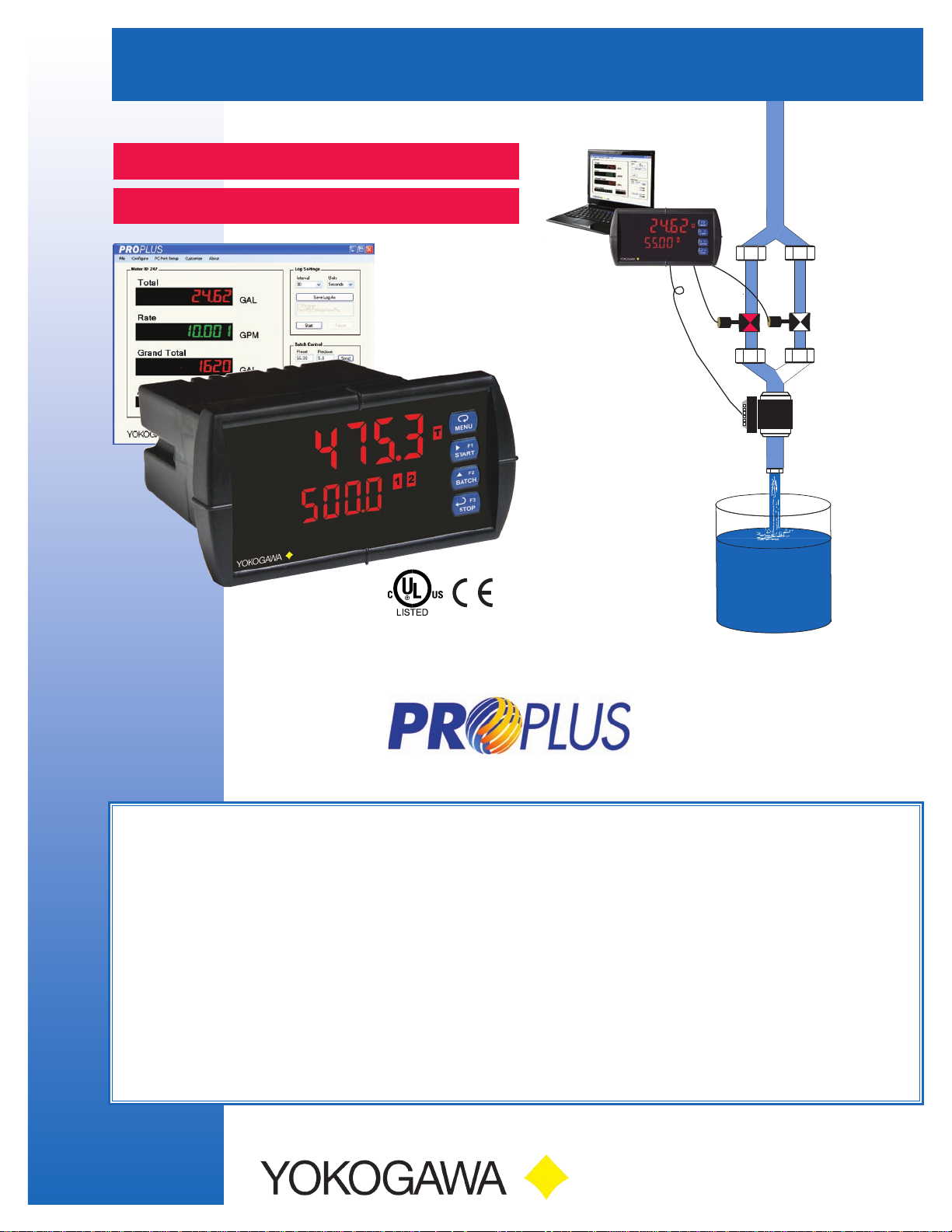
PROPLUS • Model YPP6210 Analog Input
PROPLUS • Model YPP6310 Pulse Input
BATCH CONTROL FEATURES
•Start/Pause/Stop,ChangeBatchwithFrontButtons
•DisplayBatchTotal,Rate,GrandTotal,CountorPreset
•SingleorMulti-StageBatchControl(Upto8Relays)
•AutomaticOverrunCorrection
•RateinUnitsperSecond,Minute,Hour,orDay
•AutomaticorManualBatchControl
•LoworHighFlowAlarmswhileBatching
•9DigitGrandTotalwithOverflowFeature
•CountUporDownwithEachBatch
•ProgramandControlwithaComputer
UsingPROPLUS Software
Two-Stage
Batch Control Example
ADDITIONAL FEATURES
•YPP6210:0-20mA,4-20mA,0-5V,1-5V,and
±
10VInputs
•YPP6310:Pulse,OpenCollector,NPN,PNP,TTL,
SwitchContact,SineWave(Coil),SquareWaveInputs
•LargeDual-Line6-DigitDisplay,0.60″&0.46″
•NEMA4X,IP65Front
•85-265VACor12/24VDCInputPower
•SunlightReadableDisplayModels
•2or4Relays+Isolated4-20mAOutputOptions
•External4-Relay&DigitalI/OExpansionModules
•USB,RS-232,&RS-485ModulesforModbus
®
RTU
2DartRoad•Newnan,Georgia30265
770-253-7000•800-888-6400
Fax:770-251-2088•www.yokogawa-usa.com
Page 2
YPP6210 & YPP6310 BATCH CONTROLLERS
UV Resistant
Sunlight Readable Models
Large
0.6" Digits
(Actual Size)
Rugged Front
Dual-Line
6-Character
Display
Batch Preset
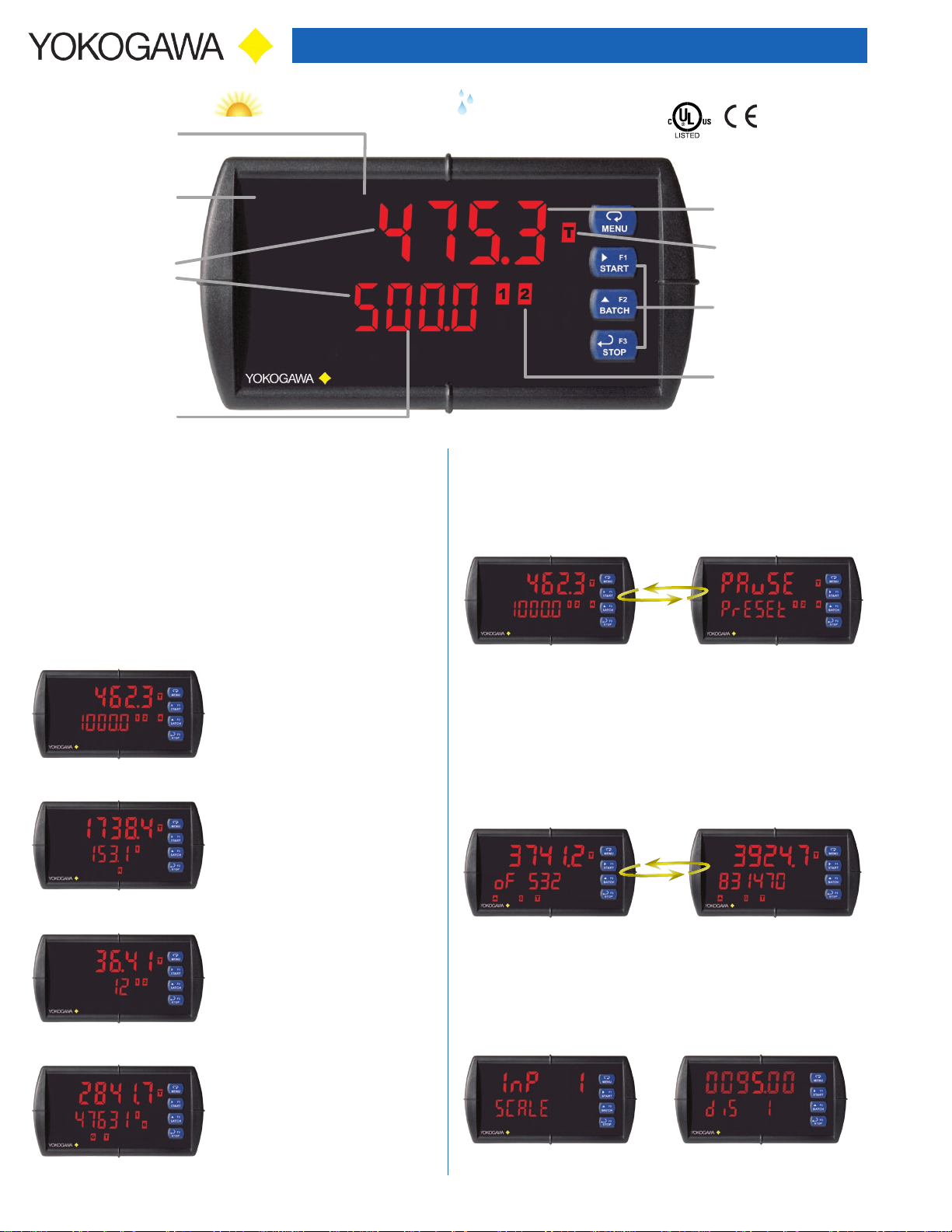
INTUITIVE BATCH CONTROL
The front panel has intuitive buttons and displays that make
operating the batch controller clear and easy right out of the box.
START, BATCH, and STOP buttons come setup by default for
batch controller operation. The START button is used to begin a
batching process. The BATCH button is used to quickly access the
preset value. The STOP button can be pressed once to pause a
batch, or twice to cancel a batch in progress. The upper and lower
displays can be easily configured for your application need.
Front Panel
NEMA 4X Rated
Current Batch
Quantity
Total
Start,
Batch Preset,
Stop Keys
Batch Control
& Alarm Relays
Clearly Labeled Displays
The upper display alternates the display to show the controller state
when in pause or stop mode. When displaying rate, grand total,
batch count, or preset, the lower display alternates between the
display value and the function or unit of measure.
Easily Choose Your Display Information
Batch Total & Preset
The preset on the lower display
provides even quicker access to
the preset menu just by using the
arrow keys to change the value.
Batch Total & Rate
The rate on the lower display may
be alternated with units for variable
flow batching systems. Rate
alarms may also be used during
the batch process.
Batch Total & Batch Count
The batch count on the lower
display, tracks completed batches.
The count may be set back to 0
with the reset menu.
Batch Total & Grand Total
A grand total with overflow digits
for up to a 9 digit total may be
displayed in the lower display,
with password protection and nonresettable programmable features.
Batch Total & Preset
Alternating Display
Grand Total Displays Up to 9 Digits
These batch controllers can display up to nine digits of total flow
with the grand total feature. In the diagrams below, the batch
controller is displaying 532,831,470 by toggling between a display
of “oF 532” and “831470”. Notice the (GT with arrow ▲ symbol) is lit
up indicating the display is in a grand total overflow mode.
Simple to Program
The user friendly dual-line display makes the PROPLUS easy to
set up & program. No jumpers to set for input selection. All setup &
programming are done via the front panel.
Input Setup Display Setup
2
Page 3
YPP6210 & YPP6310 BATCH CONTROLLERS
BATCH CONTROLLER CAPABILITIES
A PROPLUS batch controller can be programmed for a wide variety
of applications. Setup is easy for single or multi-stage batching.
Automatic overrun correction keeps the batch size accurate, even
over time and with system wear. It can record grand total, or nonresettable grand total with a time base of seconds, minutes, hours
or days. The user can program a conversion factor, and configure a
non-resettable grand total, and password protection.
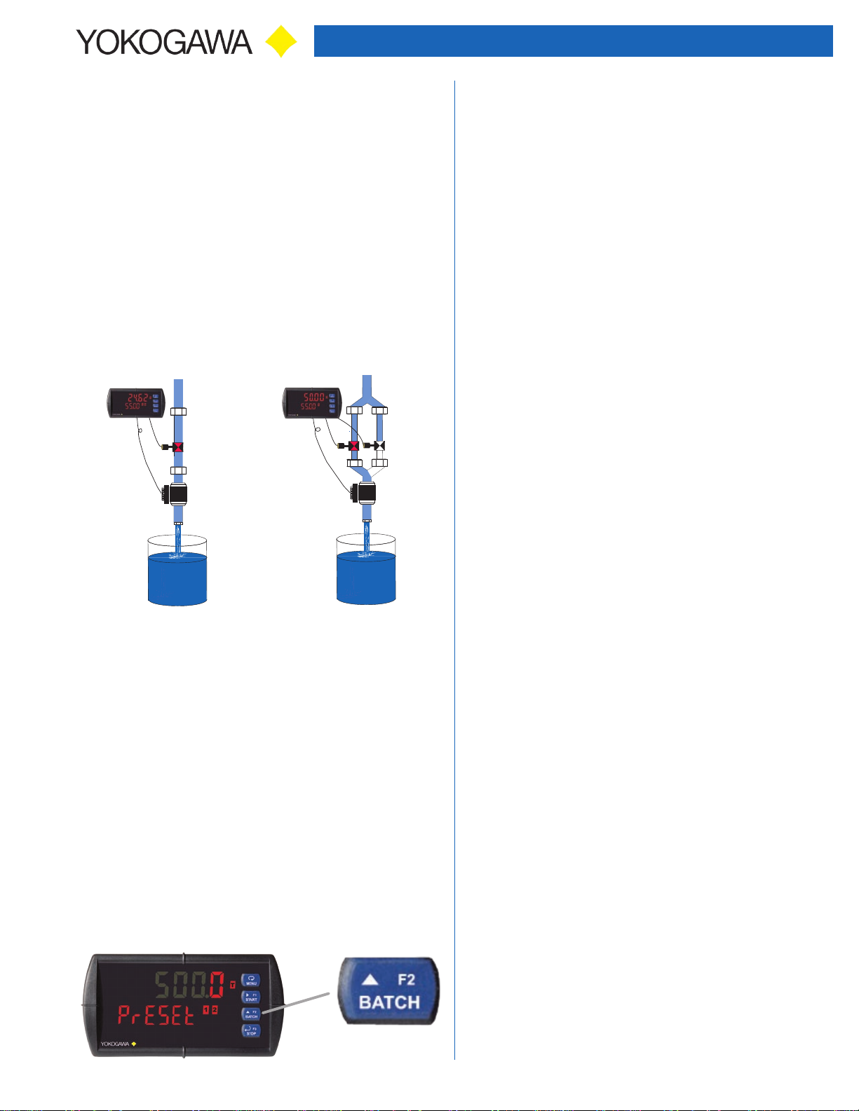
Single and Multi-Stage Batching
The PROPLUS can be used as a single or multi-stage batch
controller. Relays assigned to the total act as batch control relays,
with additional relays beyond the first including a preclose value. The
preclose deactivates the relay before the batch is finished, to allow
slower fill rates and a more accurate batch finish. With expansion
module relays, up to eight-stage batching is possible. Each
additional stage batching relay has an individually programmable
preclose amount.
Non-Resettable Grand Total
The user can set up the grand total to be non-resettable by entering
a specific password. Once this is done, the grand total can never
be reset.
Total Conversion Factor
The user can enter a conversion factor that allows the controller
to display total in different units than the rate. For instance, an
operator could measure flow rate in gallons per minute and grand
total in hundredths of acre-feet.
Grand Total & Rate Alarms
The PROPLUS’s four internal and four external relays can be set
up to alarm when the grand total reaches a user-defined set point
or when the rate is above or below a certain value. Rate alarms
are only activated when the batching process is running. A variety
of reset modes are available and the user can also program time
delays and fail-safe operation.
Relay Outputs
The PROPLUS has up to four 3 A Form C relays (SPDT) with
multiple programmable functions. One (relay 1) should always be
used for batch control. Other relays may be configured as additional
batch relays, with or without preclose for multi-stage batching or as
alarms for the rate or grand total. Each alarm has multiple power
loss fail-safe options. Alarm relays can be configured for proper
protective action upon input loop break. Alarm relay ON and OFF
delay times are user adjustable. Up to eight front panel indicators
show alarm and/or relay state. All alarm relays can be configured
for 0-100% deadband. Rate alarms are only active while a batch is
running.
Single Stage Batch Control Multi-Stage Batch Control
Manual or Automatic Batch Control
Batches may be started manually with the START front panel
button, or with a remote digital input trigger. Batches may also be
programmed to start automatically after a 0 to 999.9 second delay
after the end of the last completed batch. A manually stopped batch
will not automatically restart. The START button or digital input
must be used.
Automatic Overrun Correction
The PROPLUS batch controller will correct for batch overrun or
shortages automatically. By tracking the amount the batch was off
by, the controller will automatically adjust the batch by modifying
the batch relay deactivation time.
Quick Preset Changes
The front panel BATCH key is configured by default to access
the preset menu. The preset may be changed quickly and easily
between batches without the need to enter setup menus.
Relay Operation/Configuration
There are powerful relay functions that can be configured in the
PROPLUS controller, including:
• Single and multiple stage batch control with preclose
• Manual and automatic batch control modes
• Rate alarms during batch process
• Grand total alarms
• Sampling function
• User selectable fail-safe operation
• Relay action for loss (break) of 4-20 mA input signal (YYP6210)
• Time delay (on and off), independent for each alarm relay
Analog Output
The isolated analog retransmission signal can be configured
to represent the batch total, grand total, maximum (peak) value,
minimum (valley) value, the value for any of the eight relay set
points, manual setting control, or Modbus input. While the output is
nominally 4-20 mA, the signal will accurately accommodate underand over-ranges from 1 to 23 mA.
Isolated Transmitter Power Supplies
A powerful 24 V @ 200 mA power supply is a standard feature on
the
PROPLUS controller. It can be configured for 5, 10, or 24 V
(default) by means of a simple internal jumper (see manual). An
additional power supply (24 V @ 40 mA) is standard with the 4-20
mA output option.
3
Page 4

YPP6210 & YPP6310 BATCH CONTROLLERS
Four Types of Password Protection
The PROPLUS offers 4 types of password protection. Level 1
protection allows the operator use of only the 3 pre-configured
function keys on the front panel without a password. Level
2 protection allows the operator use of only the function keys
and the ability to change set points without a password. Level 3
protection restricts the function keys and all configuration menus
without a password. Grand total reset protection prevents the
total from being reset manually.
Environmentally Protected
The PROPLUS has standard UV protection, a NEMA 4X front panel,
extremely durable face plate, performs in wide ambient operating
temperatures, and is CE Certified (high noise and RF immunity).
Optional SunBright Display Models
PROPLUS’s SunBright display models have an extraor-
dinarily bright LED display. They are perfect for applications where the controller is in direct sunlight or in applications where visibility may be impaired by smoke, fog, dust,
or distance. This option is available on all PROPLUS models.
Rugged
A unique front panel design makes the
PROPLUS nearly impenetrable in typical
applications. Here, the PROPLUS easily
survives a direct hit on the display from a
heavy 2" solid stainless steel ball dropped
from eight feet.
FIELD EXPANSION MODULES
Add functionality to the
PROPLUS
to-install external expansion
modules. Add RS-232, RS485 communications, I/O
modules (up to 2), and 4-relay
expansion module.
items for these modules do
not appear until the module is connected, simplifying the basic menu.
Relay and digital I/O modules are shown below with optional DIN rail
mounting kit, P/N YPPA1002.
YPPA1044 I/O Expansion Module
Four digital inputs and four digital outputs are available per
expansion module. The PROPLUS controller will accept two of these
modules. External digital inputs can function similarly to the front
panel function keys.
in the field with easy-
The menu
PROPLUS SOFTWARE
Configure, monitor, control, and datalog a PROPLUS YPP6210 or
YPP6310 from a PC using
download at www.yokogawa-usa.com) and a serial adapter.
Batch Control From a Computer
Through PROPLUS Software, the preset and relay 2 preclose may
be easily changed from the main control window shown above. The
total and grand total may be reset with just the click of a button. The
batch controller may be started, paused, and stopped through the
control window, for full featured batch controller operation.
Fully Program the Controller
All the programming parameters of the controller may be configured
from
PROPLUS Software. The configuration file may be saved for
later use, and saved configuration files may be loaded into the
software for download into the
DIGITAL COMMUNICATIONS
Modbus® RTU Serial Communications
With the purchase of a serial communication adapter, PROPLUS
controllers can communicate with any Modbus Master device using
the ever-popular Modbus communications protocol that is included
in every PROPLUS. Below are some examples of other things that
can be done with PROPLUS’s Modbus communications.
• Start, pause, stop, or change preset values
• Send a 6-character message to the lower display upon an event
• Remote user control (i.e. change set points, acknowledge alarms)
• Read rate, total, grand total, batch count, etc.
PROPLUS Software (available for free
PROPLUS meter.
YPPA1004 Relay Expansion Module
An external module containing four 3 A Form A (SPST) relays can
be added to the PROPLUS at anytime. Removable screw terminal
blocks accept 12 to 22 AWG wire.
YPPA1232, YPPA1485, & YPPA8008
Communication Modules
Serial communications on the PROPLUS can be added anytime with
external YPPA1232 (RS-232), YPPA1485 (RS-485), or YPPA8008
(USB) communication adapters.
Remote MessageModbus PV Input
Controller Copy
The Copy feature is used to copy (or clone) all the settings from one
PROPLUS to other PROPLUS controllers in about 20 seconds! The
Copy function is a standard feature on all controllers. It does not
require a communications adapter, only an optional cable assembly,
P/N YPPA1200. See the ordering information for complete details.
4
Page 5

YPP6210 & YPP6310 BATCH CONTROLLERS
MANUAL MULTI-STAGE BATCH CONTROL OPERATION
System Setup
1. Both valves are closed with an empty barrel in
place. The batched total is displayed in the upper
display, the preset is selected for the lower display.
Batch Start
2. The START button is pressed, with both
valves open. The barrel begins to fill.
Preclose Valve
3. When the batch total reaches a value of 50.00
(Preset [55.00] – Preclose [5.00]) the full-flow valve
closes. The fill rate of the tank slows as a result.
F
F
F
Completed Batch
4. When the batch total equals the preset amount,
the restricted-flow valve closes. The barrel is now
full. If some overrun occurs, the next batch will
adjust for this offset amount to maintain accuracy.
Change Preset
5. After placing a new, empty barrel, a new preset
fill amount may be selected with the BATCH key,
while the process is stopped.
Begin New Batch
6. Press the START key and a new batch will begin.
With both valves open, the process continues.
Pause/Stop
7. At any time, the STOP button may be pressed,
once to Pause the process, or twice to cancel
the batch, which stops the process.
F
F
F
F
VALVE KEY LEGEND
FLOWMETER
5
F
SOLENOID
VALVE
= VALVE CLOSED
= VALVE OPEN
Page 6

YPP6210 & YPP6310 BATCH CONTROLLERS
NEMA 4X FIELD ENCLOSURES
Thermoplastic NEMA 4X enclosures are constructed for either
indoor or outdoor use.
YPPA2811
Plastic Low-Cost
YPPA2812
Plastic Low-Cost
CONNECTIONS
YPP6210
• Form C (SPDT) relays
• Two isolated power supplies available even on
12/24 VDC input power models
• Removable terminal blocks
• 2 or 4 relays + isolated 4-20 mA output option
RELAY4 RELAY3
4 36 5 2 1
COM NONO NC NC COM
SIGNAL
P- COMP+ V+ mA+
3 41 2 5
+
Transmitter
Powered by PROPLUS
-
RELAY2 RELAY1
• Universal 85-265 VAC or 12/24 VDC input power
• Voltage or current inputs
• No jumpers needed for V/mA input selection
• M-Link for adding expansion modules
YPP6 310
• Form C (SPDT) relays
• Two isolated power supplies available even on
12/24 VDC input power models
• Removable terminal blocks
• 2 or 4 relays + isolated 4-20 mA output option
• Universal 85-265 VAC or 12/24 VDC input power
• M-Link for adding expansion modules
Flowmeter
4 36 5 2 1
COM NONO NC NC COM
4-20 mA Output
Powered by
for Rate or Total
1 2 3 4 5 6 7 8
M-LINK
4-20 mA Output
Powered by
for Rate or Total
+
MA OUT
3 2
24 V
+
POWER
PROPLUS
+
PROPLUS
-
1
RI- I+
-
21
-
SPECIFICATIONS
Except where noted all specifications apply to operation at +25°C.
General
Display: Upper display: 0.60" (15 mm) high. Lower display: 0.46" (12 mm)
high. Both displays are 6 digits (-99999 to 999999), red LEDs with leading
zero blanking.
Default Display Assignment: The upper display shows batch total. The
lower display shows rate with alternating units, and can be switched to
show grand total, batch count, or preset with the STOP key.
Custom Display Assignment: The upper and lower displays may be
assigned to rate, total, grand total, batch count, preset, set points, units
(lower display only), alternating R & T, R & GT, preset & rate, max & min,
or a Modbus display register. Any rate display may be programmed to
alternate with a custom unit or tag.
Alternating Display: Displays alternate every 10 seconds when display is
selected or the batch is paused.
Display Intensity: Eight user selectable intensity levels
Display Update Rate: 5/second (200 ms)
Overrange: Display flashes 999999
Underrange: Display flashes -99999
Front Panel: NEMA 4X, IP65
Operating Methods: Three programmable front panel buttons (default
START, BATCH, STOP), digital inputs, PC and
Modbus registers.
Programming Methods: Four front panel buttons, digital inputs, PC and
PROPLUS
software, Modbus registers, or cloning using Copy function.
Noise Filter: Programmable from 2 to 199 (0 will disable filter)
Filter Bypass: Programmable from 0.1 to 99.9% of calibrated span.
Recalibration: All ranges are calibrated at the factory. Recalibration is
recommended at least every 12 months.
Max/Min Display: Max (Peak) / min (Valley) readings reached by the
process are stored until reset by the user or until power is cycled.
Password: Three programmable passwords restrict modification of
programmed settings and two prevent resetting the totals. Pass 1: Allows
use of function keys. Pass 2: Allows use of function keys, digital inputs,
and editing set/reset points. Pass 3: Restricts all programming, function
keys, and digital inputs. Gtotal password: Prevents resetting the grand total
manually.
Non-Volatile Memory: All programmed settings are stored in non-volatile
memory for a minimum of ten years if power is lost.
Power Options: 85-265 VAC 50/60 Hz, 90-265 VDC 20 W max, or jumper
selectable 12/24 VDC ±10%, 15 W max.
Fuse: Required external fuse: UL Recognized, 5 A max, slow blow; up to 6
controllers may share one 5 A fuse.
Isolated Transmitter Power Supply: Terminals P+ & P-: 24 VDC ± 5%
@ 200 mA max (standard), (12/24 VDC powered models rated @ 100 mA
max). 5 or 10 VDC @ 50 mA max, selectable with internal jumper J4.
Normal Rejection Mode: Greater than 60 dB at 50/60 Hz (YPP6210)
Isolation: 4 kV input/output-to-power line. 500 V input-to-output or
output-to-P+ supply.
Overvoltage Category: Installation Overvoltage Category II: Local level with
smaller transient overvoltages than Installation Overvoltage Category III.
Environmental: Operating temperature range: -40 to 65°C. Storage
temperature range: -40 to 85°C. Relative humidity: 0 to 90% non-condensing.
Connections: Removable screw terminal blocks accept 12 to 22 A WG wire,
RJ45 for external relays, digital I/O, and serial communication adapters.
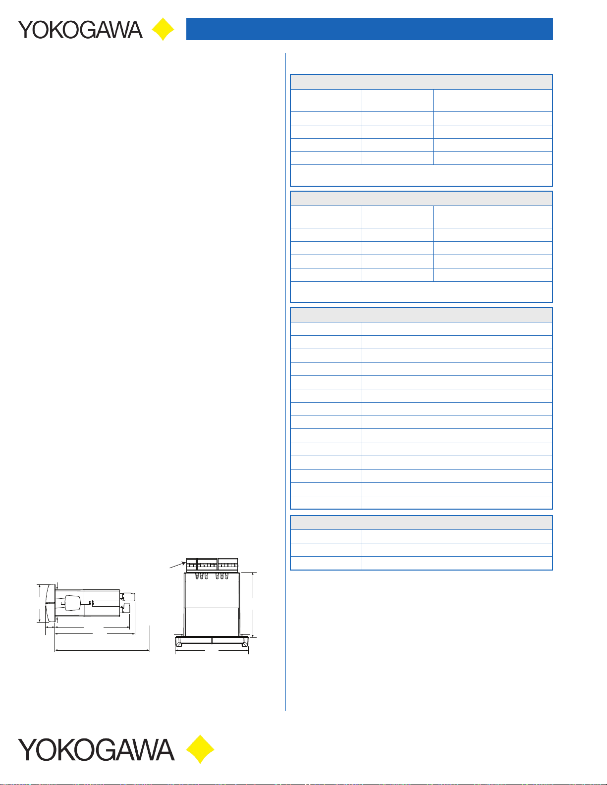
Enclosure: 1/8 DIN, high impact plastic, UL 94V-0, color: black
Mounting: 1/8 DIN panel cutout required: 3.622" x 1.772"
(92 mm x 45 mm). Two panel mounting bracket assemblies are provided.
Tightening Torque: Screw terminal connectors: 5 lb-in (0.56 Nm)
Weight: 9.5 oz. (269 g)
Overall Dimensions: 4.68" x 2.45" x 5.64"
(119 mm x 62 mm x 143 mm) (W x H x D)
UL File Number: UL & c-UL Listed. E348677; 508 Industrial Control Equipment.
Warranty: 3 years parts & labor
PROPLUS
software, and
6
Page 7

YPP6210 & YPP6310 BATCH CONTROLLERS
YPP6210 Analog Input
Input: Field selectable: 0-20, 4-20 mA, ±10 VDC (0-5, 1-5, 0-10 V),
Modbus PV (Slave)
Accuracy: ±0.03% of calibrated span ±1 count, square root &
programmable exponent accuracy range: 10-100% of calibrated span
Temperature Drift: 0.005% of calibrated span/°C max from 0 to 65°C
ambient, 0.01% of calibrated span/°C max from -40 to 0°C ambient
Signal Input Conditioning: Linear, square root, programmable exponent,
or round horizontal tank volume calculation.
Multi-Point Linearization: 2 to 32 points
Programmable Exponent: 1.0001 to 2.9999
Low-Flow Cutoff: 0-999999 (0 disables cutoff function)
Decimal Point: Up to five decimal places or none: d.ddddd, dd.dddd,
ddd.ddd, dddd.dd, ddddd.d, or dddddd.
Calibration Range:
Input Range
4-20 mA
±10 V
An error message will appear if input 1 and input 2 signals are too close together.
Minimum Span Input 1 & 2
0.15 mA
0.10 V
Input Impedance: Voltage ranges: greater than 1 MΩ.
Current ranges: 50 - 100 Ω (depending on resettable fuse impedance).
Input Overload: Current input protected by resettable fuse, 30 VDC max.
Fuse resets automatically after fault is removed.
YPP6310 Pulse Input
Input: Field selectable: Pulse or square wave 0-5 V, 0-12 V, or 0-24 V @
30 kHz; TTL; open collector 4.7 kΩ pull-up to 5 V @ 30 kHz; NPN or PNP
transistor, switch contact 4.7 kΩ pull-up to 5 V @ 40 Hz; coil (sine wave)
40 mVp-p min @ 10 kHz; Modbus PV (Slave)
Low Voltage Mag Pickup (Isolated): Sensitivity: 40 mVp-p to 8 Vp-p
Minimum Input Frequency: 0.001 Hz - Minimum frequency is dependent
on high gate setting.
Maximum Input Frequency: 30,000 Hz (10,000 for Low Voltage Mag Pickup)
Input Impedance: Pulse input: Greater than 300 kΩ @ 1 kHz. Open
collector/switch input: 4.7 kΩ pull-up to 5 V.
Accuracy: ±0.03% of calibrated span ±1 count
Display Update Rate: Total: 10/sec, Rate: 10/sec to 1/1000 sec
Temperature Drift: Rate display is not affected by changes in temperature.
Multi-Point Linearization: 2 to 32 points
Low-Flow Cutoff: 0-999999 (0 disables cutoff function)
Decimal Point: Up to five decimal places or none: d.ddddd, dd.dddd,
ddd.ddd, dddd.dd, ddddd.d, or dddddd.
Calibration: May be calibrated using K-factor, scale using internal
calibration, or calibrate by applying an external calibration signal.
K-Factor: Field programmable K-factor converts input pulses to rate in
engineering units. May be programmed from 0.00001 to 999,999 pulses/unit.
Calibration Range: Input 1 signal may be set anywhere in the range of
the controller; input 2 signal may be set anywhere above setting.
Filter: Programmable contact de-bounce filter, 40 to 999 Hz maximum
input frequency allowed with low speed filter.
Time Base: Second, minute, hour, or day
Low Gate: 0.1-99.9 seconds; this function determines how often the
incoming pulses are calculated and the rate display is updated.
High Gate: 2.0-999.9 seconds; this function determines how long to wait
for pulses before the display goes to zero. This function is used to display
slow pulse rates.
Note: The combination of the low and high gate functions makes it possible to have a fast display
update for fast pulse rates while displaying slow pulse rates, if needed. For example: If the low gate
is set to 1.0 second and the high gate to 999.9 second, with a fast pulse rate the display is updated
every second; with a slow pulse rate the controller is capable of waiting up to 999.9 seconds before
calculating the rate, making it possible to display a very slow rate down to 1 pulse/999.9 second
(0.001 pulse/second).
Batch Controller
Rate Display Indication: 0 to 999999, lead zero blanking. “R” LED
illuminates while displaying rate.
Total Displays & Grand Total Overflow: 0 to 999,999; automatic lead
zero blanking. “T” LED is illuminated while displaying batch total and
“GT” for grand total. Up to 999,999,999 with total-overflow feature. “oF” is
displayed to the left of grand total overflow and ▲ LED is illuminated.
Batch Total Decimal Point: Up to five decimal places or none: d.ddddd,
dd.dddd, ddd.ddd, dddd.dd, ddddd.d, or dddddd.
Total decimal point is independent of rate decimal point.
Totalizer: Calculates total based on rate and field programmable multiplier
to display total in engineering units. Time base must be selected according
to the time units in which the rate is displayed.
Total Conversion Factor: 0.00001 to 999,999
Batch Preset: 0.00001 to 999,999 based on batch total decimal point.
Automatic Batch Restart Delay: 00000.1 to 999.9 seconds. The batch
will automatically restart after completion of the last batch.
Grand Total Rollover: Totalizer rolls over when display exceeds
999,999,999. Relay status reflects the display value.
Grand Total Alarms: Up to seven, user selectable under Setup menu.
Any set point can be assigned to grand total and may be programmed
anywhere in the range of the controller for grand total alarm indication.
Note that Relay 1 should always be assigned to batch control (total).
Grand Total Reset: Via front panel button, external contact closure on
digital inputs, automatically via user selectable preset value and time
delay, or through serial communications.
Grand Total Reset Password: A grand total password may be entered to
prevent resetting the grand total from the front panel.
Non-Resettable Grand Total: The grand total can be programmed as a
non-resettable total by entering the password “050873”.
Caution: Once the Grand Total has been programmed as “non-resettable” the feature cannot be disabled.
Relays
Rating: 2 or 4 SPDT (Form C) internal and/or 4 SPST (Form A) external;
rated 3 A @ 30 VDC and 125/250 VAC resistive load; 1/14 HP (≈ 50 W) @
125/250 VAC for inductive loads
Noise Suppression: Noise suppression is recommended for each relay
contact switching inductive loads.
Relay Assignment: Relays may be assigned to batch control, sampling,
rate, or grand total alarms.
Preclose: 0-100% of batch size, individually user programmable for each
additional batch control relay beyond the first.
Alarm Deadband: 0-100% of span, user programmable
High or Low Alarm: User may program any alarm for high or low trip
point. Unused alarm LEDs and relays may be disabled (turned off).
Batching Relay Operation: Single or (2 to 8) multi-relay batching with
optional preclose for multi-stage operation. Each additional relay may be
programmed with an individual preclose value.
Alarm Relay Operation: automatic (non-latching), latching (requires
manual acknowledge), sampling (based on rate or grand total), pump
alternation control (2 to 8 relays), off (disable unused relays), and manual
on/off control mode. Alarms are active only when the batch is running.
Alarm Relay Reset: User selectable via front buttons, digital inputs, or PC
1. Automatic reset only (non-latching), when input passes the reset point
or total is reset to zero.
2. Manual reset only, when batch is stopped (latching).
3. Manual reset only after alarm condition has cleared (latching)
Note: Front panel button or digital input may be assigned to acknowledge relays programmed for
manual reset. This replaces one of the standard batch control function keys. Only the PAUSE/STOP
key function is possible during a batch process, so manual reset may only be done when the
controller is in STOP mode.
Deadband: 0-100% of span, user programmable
Time Delay: 0 to 999.9 seconds, on & off relay time delays. Programmable
and independent for each relay.
Fail-Safe Operation: Programmable and independent for each relay.
Note: Relay coil is energized in non-alarm condition. In case of power failure, relay will go to alarm state.
Auto Initialization: When power is applied, relays will reflect the state of
the input. Alarms are active only when the batch is running.
7
Page 8
YPP6210 & YPP6310 BATCH CONTROLLERS
Isolated 4-20 mA Transmitter Output
Output Source: Rate/process, total, grand total, max, min, set points 1-8,
manual control setting, or Modbus input
Scaling Range: 1.000 to 23.000 mA for any display range
Calibration: Factory calibrated: 4.000 to 20.000 = 4-20 mA output
Analog Output Programming: 23.000 mA maximum for all parameters:
Overrange, underrange, max, min, and break
Accuracy: ± 0.1% FS ± 0.004 mA
Temperature Drift: 0.4 μA/°C max from 0 to 65°C ambient,
0.8 μA/°C max from -40 to 0°C ambient
Note: Analog output drift is separate from input drift.
Isolated Transmitter Power Supply: Terminals I+ & R: 24 VDC ± 5%
@ 40 mA maximum, may be used to power the 4-20 mA output or other
devices. Present on both AC & DC powered units.
External Loop Power Supply: 35 VDC maximum
Output Loop Resistance:
Power supply Minimum Maximum
24 VDC 10 Ω 700 Ω
35 VDC (external) 100 Ω 1200 Ω
Serial Communications
Protocol: Modbus® RTU
Controller Address/Slave ID: 1 - 247
Baud Rate: 300 - 19,200 bps
Transmit Time Delay: Programmable between 0 and 199 ms
Data: 8 bit (1 start bit, 1 or 2 stop bits)
Parity: Even, odd, or none with 1 or 2 stop bits
Byte-to-Byte Timeout: 0.01 - 2.54 seconds
Turn Around Delay: Less than 2 ms (xed)
Note: Refer to the YPP6000/YPP7000 Modbus Register Tables located at
www.yokogawa-usa.com for details.
Digital I/O Expansion Module
Channels: 4 digital inputs & 4 digital outputs per module
System: Up to 2 modules for a total of 8 inputs & 8 outputs
Digital Input Logic: High: 3 to 5 VDC Low: 0 to 1.25 VDC
Digital Output Logic: High: 3.1 to 3.3 VDC Low: 0 to 0.4 VDC
Source Current: 10 mA maximum
Sink Current: 1.5 mA minimum
+5 V Terminal: To be used as pull-up for digital inputs only.
4-Relay Expansion Module
Relays: Four Form A (SPST) rated 3 A @ 30 VDC and 125/250 VAC
resistive load; 1/14 HP (≈ 50 watts) @ 125/250 VAC for inductive loads.
R
C
+
C
NO
NC
NC
-
NO
C
C
NO
NC
NC
DIMENSIONS
1.76"
(45 mm)
Optional
Connectors
Installed
NO
ORDERING INFORMATION
PROPLUS YPP6210 Analog Input
85-265 VAC
Model
YPP6210-6R2 YPP6210-7R2 2 Relays
YPP6210-6R4 YPP6210-7R4 4 Relays
YPP6210-6R5 YPP6210-7R5 2 Relays & 4-20 mA Output
YPP6210-6R7 YPP6210-7R7 4 Relays & 4-20 mA Output
To order SunBright display models replace the “R” with “H” (i.e. YPP6210-6H2)
Note: 24 V flowmeter power supply standard on all models.
85-265 VAC
Model
YPP6310-6R2 YPP6310-7R2 2 Relays
YPP6310-6R4 YPP6310-7R4 4 Relays
YPP6310-6R5 YPP6310-7R5 2 Relays & 4-20 mA Output
YPP6310-6R7 YPP6310-7R7 4 Relays & 4-20 mA Output
To order SunBright display models replace the “R” with “H” (i.e. YPP6310-6H2)
Note: 24 V flowmeter power supply standard on all models.
Model Description
YPPA1002 DIN Rail Mounting Kit for Two Expansion Modules
YPPA1004 4-Relay Expansion Module
YPPA1044 4 Digital Inputs & 4 Digital Outputs Module
YPPA1200 Controller Copy Cable
YPPA1232 RS-232 Serial Adapter
YPPA1485 RS-485 Serial Adapter
YPPA7485-I RS-232 to RS-422/485 Isolated Converter
YPPA7485-N RS-232 to RS-422/485 Non-Isolated Converter
YPPA8008 USB serial adapter
YPPA8232-N USB to RS-232 Non-Isolated Converter
YPPA8485-I USB to RS-422/485 Isolated Converter
YPPA8485-N USB to RS-422/485 Non-Isolated Converter
YPPX6901 Suppressor (snubber): 0.01 μF/470 Ω, 250 VAC
Model Description
YPPA2811 1 Meter Plastic NEMA 1 Batch Controller
YPPA2812 2 Meter Plastic NEMA 2 Batch Controllers
12/24 VDC
Model
Options Installed
PROPLUS YPP6310 Pulse Input
12/24 VDC
Model
Accessories
Enclosures
Options Installed
2.45"
(62 mm)
(15 mm)
Notes:
0.59"
(121 mm)
4.77"
5.05"
6" (152 mm) Clearance
(128 mm)
Side View
3.61"
(92 mm)
1. Panel cutout required: 1.772" x 3.622" (45mm x 92mm)
2. Panel thickness: 0.040 - 0.250" (1.0mm - 6.4mm)
3. Mounting brackets lock in place for easy mounting
4. Clearance: Allow 6" (152 mm) behind the panel
4.17"
(106 mm)
4.68"
(119 mm)
Top View
Disclaimer
The information contained in this document is subject to change without notice. Yokogawa
Corporation of America makes no representations or warranties with respect to the contents
hereof, and specically di sclaims a ny implied w arranti es of merc hantability or t ness for a
particular purpose.
©2011 Yokogawa Corporation of America. All rights reserved
2DartRoad•Newnan,Georgia30265
770-253-7000•800-888-6400
Fax:770-251-2088•www.yokogawa-usa.com
LDS6210_B 11/11
 Loading...