

Page 1
User's
Manual
CA450
Process Multimeter
99 Washington Street
Melrose, MA 02176
Phone 781-665-1400
Toll Free 1-800-517-8431
Visit us at www.TestEquipmentDepot.com
Store this manual in an easily
accessible place for quick reference.
6th Edition: Aug. 2018 (YMI)
IM CA450-EN
Page 2

Introduction
Thank you for purchasing our CA450 Process Multimeter.
This User’s Manual explains the functions of this Process Multimeter, as well as
the operating methods and handling precautions.
Before using this product, thoroughly read this manual to understand
how to use it properly.
■ List of Manuals
The following manuals, including this one, are provided as manuals for the CA450.
Please read all manuals.
IM CA450-EN User's Manual (this manual)
IM CA450-93Z2
Document for Korea
Contact information of
the following sheet.
PIM 113-01Z2
Yokogawa ofces worldwide is provided on
Inquiries
List of worldwide contacts
■ Notes
• The information contained in this manual is subject to change without notice.
Furthermore, the actual display ite
appearing in this manual.
• Every effort has been made to ensure the information contained herein is
accurate. However, should any concerns, errors, or emissions come to your
attention, or if you have any comments, please contact us.
• Copying or reproduction of any or all of the content of this manual without
YOKOGAWA's permission is strictly prohibited.
ms may differ slightly from the ones
■ Registered Trademarks
“HART” is a registered trademark of the HART Communication Foundation.
Disk No. IMCA450-EN
6th Edition: August 2018 (YMI)
All Rights Reserved, Copyright ©
2010 Yokogawa Test & Measurement Corporation
Printed in Japan
IM CA450-EN i
Page 3
■ Revision Information
1st Edition: October 2010
2nd Edition: February 2011
3rd Edition: March 2015
4th Edition: October 2016
5th Edition: October 2017
6th Edition: August 2018
Checking the Contents of the Package
After receiving the product and opening the package, check the items described below.
If the wrong items have been delivered, if items are missing, or if there is a problem
with the appearance of the items, contact your nearest YOKOGAWA dealer.
• Model and Sufx Codes
Model Sufx Code
CA450 -E
• NO. (Serial Number)
Refer to this serial number on the nameplate when contacting the vendor about
the instrument.
(For the model, nameplate, and serial number, see section 4.2, “Components.”)
• Standard Accessories
Make sure that the package contains all the accessories listed below and that
they are all free from any damage.
Standard accessories are not covered by warranty of this instrument.
AA-size alkaline batteries 4 pieces
Test leads (98073) 1 set
Lead cables (98064) 1 set
Fuses (inside the CA450) (99042) 440 mA/1000 V 2 pieces
User’s manual 1 copy
Blank cover 1 piece
ii IM CA450-EN
Page 4

Regarding Safe Use of This Product
WARNING
CAUTION
Note
Tip
This product is designed to be used by a person with specialized knowledge.
When operating the instrument, be sure to observe the cautionary notes given
below to ensure correct and safe use of the instrument.
If you use the instrument in any way other than as instructed in this manual,
the instrument’s protective measures may be impaired.
This manual is an essential part of the product; keep it a safe place for
future reference.
YOKOGAWA is by no means liable for any damage resulting from use of
the instrument in contradiction to these cautionary notes.
The following safety symbols are used on the instrument and
in the manual:
This indicates that the operator must refer to an explanation in the instruction
manual in order to avoid the risk of serious injury or the loss of life.
This indicates that the operator must refer to an explanation in the instruction
manual in order to avoid the risk of injury or damage to the product.
This indicates information that is essential for handling the instrument or
should be noted in order to familiarize yourself with the instrument’s operating
procedures and/or functions.
This indicates supplemental information for explanations.
IM CA450-EN iii
Page 5
Danger! Handle with Care
WARNING
This symbol indicates that the operator must refer to an explanation
in the instruction manual in order to avoid risk of injury or death of
personnel or damage to the instrument.
This symbol indicates double insulation or reinforced insulation.
This symbol indicates DC voltage/current.
This symbol indicates AC voltage/current.
This symbol indicates AC and DC.
This symbol indicates a fuse.
This symbol indicates a battery.
This symbol indicates ground (earth).
■ Always observe the following instructions.
Failure to do so
may result in electrical shock or other dangers that
may lead to serious injury or the loss of life.
Use the instrument Only for Its Intended Purpose
This instrument is for measuring voltage or current and generating (output) current.
Do not use this instrument for other purpose.
Check the Physical Appearance
Do not use the instrument if there is a problem with its physical appearance.
Operating Environment
• Do not operate the instrument in an atmosphere where any ammable or
explosive gas ispresent.
• Avoid using the instrument if it has been exposed to rain or moisture or
if your hands are wet.
iv IM CA450-EN
Page 6

WARNING
CAUTION
Test Leads and Lead cables
• Use the products provided by YOKOGAWA for this device.
• Do not use degraded or damaged test leads or lead cables.
Check the continuity of the test leads and lead cables.
• When you attach or remove the test leads or lead cables or remove the case
(for example to change the batteries), be sure to remove the lead cables
from the circuit under measurement.
• When you remove the case (for example to change the batteries),
be sure to remove the test leads and lead cables from the instrument.
• There are caps at the ends of the test leads.
To ensure safety (safety standard EN 61010-031), be sure to put the caps on
the leads when you use them.
Damaged Signal Cable
If the signal cable (test leads and lead cables) is torn and the inner metal is
exposed or if a color different from the outer sheath appears, stop using
the cable immediately.
Casing
Do not use the instrument if there is any damage to the casing or
when the casing is removed.
Fuses
Use fuses of the specied rating when the fuse is replaced.
Do Not Remove the Case or Disassemble
Do not open the case except when replacing batteries or fuse.
Only Yokogawa service personnel are authorized to remove the casing or
disassemble or modify the instrument.
Do not attempt to repair the instrument yourself, as doing so is extremely
dangerous.
When the instrument needs an internal inspection or calibration,
contact YOKOGAWA or the dealer from whom you purchased the instrument.
The instrument is for domestic use (Class B) and meets the electromagnetic
compatibility requirements.
IM CA450-EN v
Page 7
Concernant l’usage en toute sécurité de ce produit
AVERTISSEMENT
ATTENTION
Remarque
Conseil
Dans le cadre de l'utilisation de cet instrument, assurez-vous de respecter
les mises en garde indiquées ci-dessous pour garantir une utilisation correcte
et sans danger de l'instrument. Si vous utilisez l'appareil d'une autre manière
que celle indiquée dans ce manuel, il est possible que cela endommage
les dispositifs de protection.
YOKOGAWA ne saurait en aucun cas être déclaré responsable de
tout dommage résultant d'une utilisation de l'instrument ne respectant pas
ces mises en garde.
Symboles utilisés sur l'instrument et dans ce manuel d’instructions:
Indique un danger. Attire l’attention sur une utilisation quipourrait engendrer
des accidents susceptibles de provoquer des blessures qui peuvent
éventuellement s’avérer mortelles.
Indique un danger. Attire l’attention sur une utilisation qui pourrait engendrer
une blessure personnelle et/ou être préjudiciable au produit.
Indique les informations essentielles à la manipulation de l’instrument ou qui
doivent être prises en compte an de vous familiariser avec les procédures
d’utilisation et/ou l es fonctions de l’instrument.
Ce qui suit indique des informations supplémentaires pour les explications.
vi IM CA450-EN
Page 8
Danger ! Manipuler avec soin.
AVERTISSEMENT
Ce symbole indique que l’opérateur doit se reporter à une
explicationdonnée par le manuel d’instruction, an d’éviter tout
accident susceptible de provoquer des blessures au personnel qui
peuvent éventuellement s’avérer mortelles, ou de protéger l’appareil.
Ce symbole indique une double isolation ou une isolation renforcée.
Ce symbole indique une tension/intensité C.C.
Ce symbole indique une tension/intensité C.A.
Ce symbole indique le C.A. et le C.C.
Ce symbole indique un fusible.
Ce symbole indique une batterie.
Ce symbole indique la masse (terre).
■ Les précautions suivantes doivent être prises. Dans le cas contraire,
des accidents susceptibles de provoquer des blessures qui peuvent
éventuellement s’avérer mortelles résultant de dangers tels que des
chocs électriques, ou un préjudice au produit, risquent de survenir.
Utilisez cet instrument uniquement pour l'usage auquel il est destiné.
Cet instrument est destiné à mesurer une tension ou un courant et à générer
du courant (sortie). N'utilisez pas cet instrument à d'autres ns.
Vériez l'aspect physique
N'utilisez pas cet instrument si son aspect physique présente un problème.
Environnement d’opération
• N’utilisez pas l’instrument là où un gaz ou de la vapeur (atmosphère)
inammable ou explosive quelconque est présente.
• Évitez d’utiliser l’instrument s’il a été exposé à la pluie ou à l’humidité ou si
vos mains sont humides.
IM CA450-EN vii
Page 9

AVERTISSEMENT
ATTENTION
Fils de test et câbles de dérivation
• Utilisez les produits fournis par YOKOGAWA pour ce dispositif.
• N'utilisez pas de ls de test ou de câbles de dérivation dégradés ou
endommagés.
Vériez la continuité des ls de tes
• Lorsque vous xez ou retirez les ls de test ou les câbles de dérivation,
ou que vous enlevez le boîtier (par exemple pour changer les batteries),
veillez à retirer les ls de test et les câbles de dérivation du circuit en cours
de mesure.
• Lorsque vous enlevez le boîtier (par exemple pour changer les batteries),
veillez à retirer les ls de test et les câbles de dérivation de l'instrument.
• Un chapeau est fourni sur le bout d’un l de test.
Utilisez un l de test avec le chapeau placé dessus pour une bonne sécurité
(normes de sécurité: EN 61010-031).
t et des câbles de dérivation.
Câble de signal endommagé
Si le câble de signal (des ls de test et des câbles de dérivation) est déchiré et que
le métal intérieur est exposé ou si une couleur différente de la gaine externe est
visible, arrêter immédiatement d’utiliser ce câble.
Boîtier
N’utilisez pas l’instrument s’il y a un dommage quelconque au boîtier ou quand
le boîtier est enlevé.
Fusibles
Utilisez les fusibles avec l’évaluation spéciée quand le fusible est remplacé.
Ne retirez pas le boîtier, ne le démontez pas.
N'ouvrez pas le boîtier, sauf pour remplacer la batterie ou un fusible.
Seul le personnel qualié de YOKOGAWA est habilité à retirer le boîtier et
démonter ou modier l'instrument. N'essayez pas de réparer/modier l'instrument
vous-même, car cela est extrêmement dangereux.
Pour un contrôle interne ou un étalonnage de l’instrument, contacter
YOKOGAWA ou le revendeur auprès duquel a été acheté l’instrument.
Cet instrument est destiné à un usage domestique (classe B) et respecte les
exigences en matière de compatibilité électromagnétique.
viii IM CA450-EN
Page 10
Contents
Introduction .....................................................i
Checking the Contents of the Package............................... ii
Regarding Safe Use of This Product.................................iii
Concernant l’usage en toute sécurité de ce produit .....................vi
1. Overview................................................... 1
2. Operating Environment ........................................ 2
3. Specications ............................................... 4
3.1 General Specications.................................... 4
3.2 Accuracy ..............................................7
4. Operation .................................................10
4.1 Precautions before Measurement .......................... 10
4.2 Components........................................... 11
4.3
Measuring Instructions................................... 18
4.3.1
4.3.2 DC Voltage Measurement
4.3.3 Measuring Using Sensors (SENSOR)................. 19
4.3.4 Resistance Measurement (Ω) ....................... 20
4.3.5 Continuity Check
4.3.6 Diode Test
4.3.7 DC Current Measurement
4.3.8
4.3.9
4.3.10 Auto Hold Function ...............................27
4.3.11 Peak Hold Function ...............................27
4.3.12 Relative Value Display
4.3.13 MIN/MAX/AVG Function ...........................30
4.4 Output Instructions...................................... 31
4.4.1 Constant Current Output (SOURCE mode)............. 32
4.4.2 Constant Current Output (SIMULATE mode) ...........34
4.4.3
4.4.4 Current Span Setting .............................. 38
4.5 Auto Power-Off (Sleep) Function........................... 38
oltage Measurement
AC V
............................ 21
................................. 21
Loop Power Measurement..........................25
Frequency Measurement (Hz)....................... 26
Current Sweep Output............................. 36
............... 18
............... 18
....................23
.................. 29
IM CA450-EN ix
Page 11

4.6 Setup Function......................................... 39
4.6.1 Turning the Buzzer On and Off ......................40
4.6.2 SENSOR Mode Input, Display, and Unit Settings ........41
4.6.3 Current Span Setting for the 100 mA Range for DCmA
Measurement
4.6.4
Setting the Slow Step
4.6.5
Returning the Settings to
4.7
Additional Po
4.7.1
Making
5.
User Calibratio
5.1 Cali
5.1.1
5.1.2 Loop Power Calibration ............................48
5.2 Calibrating Output ......................................49
5.3 What to Check after Calibration............................ 51
6. Communication............................................. 52
6.1 Cable Connection and Interface Specications ................ 52
6.2 Communication Commands............................... 53
6.3 Detailed Command Descriptions ...........................55
6.4 List of Errors...........................................73
6.5
Communication Command V
6.6 Status Byte Format .....................................76
Replacing the
7.
7.1 Replacing th
7.2
Replacing th
8.
Calibration and
Troubleshooting ............................................
9.
10. Sales in Each
10.1 Disposing the
10.2
How to Replace and Dispose th
10.3
Authorized R
10.4
For the Pollu
Products of the People's Republic of China
Appendix (External Dimensions)................................... 84
n Function
brating Measurements
Peak Hold Calibration ............................. 48
Batteries and Fuses
e Batteries ..................................
e Fuses ....................................
After-Sales Service .............................
Country or Region
epresentative in the EEA
tion Control of Electronic and Electrical
....................................42
Time . . . . . . . . . . . . . . . . . . . . . . . . . 43
Their Factory Default Values
wer-on Functions ............................
All the LCD Elements Appear
.....................................45
................................46
alidity Table
..............................77
...............................82
Product ...................................
e Batteries
................. 44
.................... 74
................... 82
....................... 82
................... 83
.... 43
44
77
78
79
81
82
x IM CA450-EN
Page 12

1. Overview
• Display
Main display: 5-digit LCD, Subdisplay: 5-digit LCD
(Measured values other than current values are displayed with 4 digits.)
• Various Functions
Measurement Functions
DC voltage, AC voltage, DC current (24 V loop power supply possible),
resistance, frequency, continuity check, and diode test
Output Functions
DC current (constant output, current sweep output, and
SIMULATE (SINK) function)
Additional Functions
Data hold (D•H); auto hold (A•H); peak hold (P•H); auto range (Auto);
range hold (Range Hold); maximum, minimum, and average value recording
and measurement; zero adjustment (Ω); relative measured value display
(RELΔ, REL%); and backlight
• Communication (Optional PC communication set required)
Measurement data can be transferred to a PC through the use of
a USB communication adapter and a USB cable.
• Safety
Conforms to IEC 61010-1, Safety requirements for electrical equipment for
measurement, control, and laboratory use.
“Safety requirements for electrical equipment for measurement, control, and
laboratory use”
This instrument uses a current-input terminal shutter for preventing wrong input.
This instrument uses high-performance UL-standard fuses.
IM CA450-EN 1
Page 13
2. Operating Environment
WARNING
■ Measurement Category
Measurement
Category
O
(None, Other)
CAT II For measurements performed on circuits
CAT III For measurements performed in the building
CAT IV For measurements performed at the source
Other circuits that are not directly
connect to MAINS.
directly connected to the low-voltage
installation
installation.
of the low-voltage installation.
■ Measurement Category of CA450
There are restrictions on the maximum voltage level at which the CA450 can
be used. These restrictions are based on the measurement categories specied
by the safety standards.
AC/DC 1000 V CAT III, AC/DC 600 V CAT IV
Current measurement and output:
Measurement category O (Other) 48 Vmax 100 mAmax
■ Category of Lead cables (98064)
Measurement category O (Other) DC 70V 100 mA
■ Category of Test leads (98073)
With Caps: 1000V 10A CAT III/600V 10A CAT IV
Without Caps: 1000V 10A CAT II
Description Remarks
Circuits not connected to a
mains power source
Appliances, portable
equipment, etc.
Distribution board, circuit
breaker, etc.
Overhead wire, cable
systems, etc.
When you use the test leads, attach or remove the caps according to
the measurement category.
2 IM CA450-EN
Page 14

CAUTION
Note
The instrument is for domestic use (Class B) and meets the electromagnetic
compatibility requirements.
Radiation immunity affects electrical performance (accuracy) under
the conditions in EN 61326-1 and EN 61326-2-2.
The use of this instrument is limited to domestic, commercial,
and light industry applications.
The instrument may malfunction if it is exposed to strong electromagnetic
interference from nearby devices.
Operating Environment and Conditions
This instrument complies with the EMC standard under specic operating
environment and operating conditions.
If the installation, wiring, and so on are not appropriate,
the compliance conditions of the EMC standard may not be met.
In such cases, the user will be required to take appropriate measures.
■ Operating Environment
Do not use the instrument in the following locations:
• Outdoors
• In direct sunlight or near heat sources
• Where the instrument is exposed to water or other liquids
• Where there is a lot of mechanical vibration
• Near noise sources such as high-voltage equipment or power lines
• Near strong magnetic eld sources
• Where an excessive amount of greasy fumes, steam, dust, or corrosive
gases are present
• In an unstable place
• Where, for example, re and explosions caused by inammable gases and
the like are possible
IM CA450-EN 3
Page 15
3. Specications
3.1 General Specications
Measurement functions: DC voltage, AC voltage, DC current, resistance, frequency,
continuity check, diode test
Additional functions: Data hold (D•H); auto hold (A•H); peak hold (P•H);
auto range (
maximum, minimum, and average value recording
measuremen
relative mea
24 V loop power supply; internal resistor on/off
for HART communication
Output functions:
current output SIMULA
Additional functions:
Operation methods:
Output: Multiplicative DA
Display:
Numeric display
Subdisplay Displays supplemental information
for various functions
Polarity indicator
Over range indicator “OL”
Low-battery indicator
the operating voltage.
Measurement cycle: 2.5 to 5 times a second
(however, frequency measurement takes place once a second)
5-digit LCD (7 segment)
20 mA
Current span
Measurement:
DC current: 33000 DC current: 25000
Frequency: 19999 --Other: 6600 ---
Auto); range hold (Range Hold);
t; zero adjustment (Ω);
sured value display (REL
DC current for current output SOURCE and
switching and current sweep output
TE (SINK)
Σ modulation
, REL%);
Measurement Output
Automatic display
appears when the battery voltage is below
. Only the minus sign “–” appears.
and
IM CA450-EN4
Page 16

Operating temperature and humidity: -20°C to 55°C (80% RH or less)
with no condensation
Within the range of 40°C to 55°C,
the humidity must be 70% RH or less.
Storage temperature and humidity:
with no condensation
emperature coefcient (typ.):
T
add the accuracy of 23°C ± 5°C × 0.1/°C.
Power supply:
Battery life:
DC voltage measurement: Approx. 140 hours
DC current output (SIMULATE): Approx. 140 hours
DC current output (SOURCE) 12 mA (500 Ω load):
Approx. 10 hours
Insulation resistance:
Withstand voltage:
(between the input terminals and the case)
External dimensions:
(For external dimensions, see
Weight:
-40°C to 70°C (70% RH or less)
In the ranges of -20°C to 18°C and 28°C to 55°C,
AA-size alkaline batteries (1.5 V LR6)
Four
When using alkaline batteries
100 MΩ or greater at 1000 VDC
AC for ve seconds
6.88 kV
Approx. 90 (W) × 192 (H) × 49 (D) mm
Approx. 600 g (including the batteries)
Appendix.)
Standard accessories:
T
Lead cables (98064)
Fuses (99042)
440 mA/1000 V (inside the CA450)
User
Blank cover
Optional accessories:
(for carrying the CA450, the test leads, and the lead cables)
Carrying case (93043-P1) 1 piece
Test leads (98073) 1 set
Lead cables (98064)
Alligator test leads (99014) 1 set
Fuse 440 mA/1000 V (99042) 2 pieces
Communication Package (92015)
(USB adapter
1 to 5V
(250 Ω resistor
AC/DC clamp-on probe (96095)
Clamp-on probe for current (96001)
AA-size alkaline batteries
est leads (98073)
’s manual
Carrying case (93029)
Adapter set (99031)
, USB cable and software)
, terminal adapters and leads)
4 pieces
1 set
1 set
2 pieces
1 copy
1 piece
1 piece
1 set
1 set
1 set
1 piece
1 piece
5IM CA450-EN
Page 17

Safety standards: EN 61010-1, EN 61010-2-030, EN 61010-2-033, EN 61010-031
Measurement Categories: 1000 V CA
For current measurement and output: 48 V max, 100 mA
Measurement category O (Other)
Lead cables (98064): 70 VDC, 100 mA
Measurement category O (Other)
Indoor use, altitude: 2000 m or less, pollution degree 2
V
Amplitude 0.15 mm (peak value)
Duration 30 minutes
Shock: 1 m drop test as dened by the safety standards
ibration:
Sweep vibration frequencies 10 Hz to 55 Hz to 10 Hz
TIII, 600 V CATIV
max
EMC standards:
EN 55011 Class B Group 1
EMC Regulatory Arrangement in Australia and New Zealand
EN 55011 Class B Group 1
Korea Electromagnetic Conformity Standard
(한국전자파적합성기준)
Inuence of radiated immunity: In RF electromagnetic elds of 3 V/m
EN 61326-1
AC voltage measurement, 600 mV range: 1.5% of range
DC voltage measurement, 600 mV range: 1% of range
DC current measurement, all ranges: 1.5% of range
DC current output: 1.5% of range
EN 61326-2-2
AC voltage measurement (6 V range or higher):
Within 5 times the accuracy
DC voltage measurement (6 V range or higher):
Within 5 times the accuracy
EN 61326-1 Class B, EN6 1326-2-2
Environmental standard EN 50581
Monitoring and control instruments including industrial
monitoring and control instruments
IM CA450-EN6
Page 18
3.2 Accuracy
Standard test conditions
(1) Ambient temperature:
(2) Relative humidity:
(3) Orientation:
Horizontal or standing
(4) External magnetic elds:
Accuracy: ± (% of reading + digits)
* Each of the response times indicates the time it takes for the accuracy to
fall within the specied range.
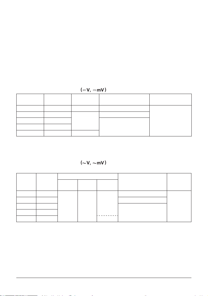
DC Voltage Measurement
Range Resolution Accuracy Input Resistance
600 mV 0.1 mV 0.09% + 2 10 MΩ or more
6 V 0.001 V
60 V 0.01 V
1000 V 1 V 0.1% + 1
NMRR: 60 dB or more, 50/60 Hz ± 0.1%
CMRR: 120 dB or more, 50/60 Hz (Rs = 1 kΩ)
Response time: Within 1 second
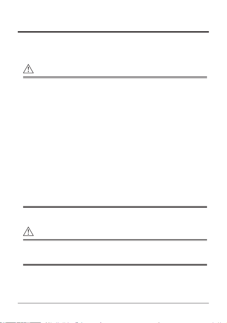
AC Voltage Measurement
AC coupling, rms value detection: sine wave
Range
600 mV 0.1 mV
For a range of 5 to 100%, the accuracy for the 1000 V range is 200 V to 1000 V
CMRR: 60 dB or more, DC to 60 Hz (Rs = 1 kΩ)
For nonsinusoidal waveforms whose crest factor is less than 3,
add ±(2% of reading + 2% of range) to the accuracy.
For the 1000 V range, the peak voltage is 1500 V or less
Response time: Within 2 seconds
Resolution
50/60 Hz
6 V 0.001 V
60 V 0.01 V
0.5% + 5 1% + 5
600 V 0.1 V
1000 V 1 V —
23°C ± 5°C
45% to 75% RH (no condensation)
errestrial magnetic eld only
T
Approx. 11 MΩ
0.09% + 1
Approx. 10 MΩ600 V 0.1 V
Accuracy
40 Hz to
500 Hz
500 Hz to
1 kHz
1.5% + 5
Impedance
10 MΩ or more, <200 pF
Approx. 11 MΩ, <50 pF
Approx. 10 MΩ, <50 pF
Maximum Input
1000 VDC
1000 Vrms AC
Input
Voltage
Maximum
Input
Voltage
1000 VDC
1000 V
rms AC
7IM CA450-EN
Page 19

DC Current Measurement
Range Resolution Accuracy Voltage Drop
30 mA 0.001 mA 0.05% + 2 < 0.3 V
100 mA *1 0.01 mA 0.05% + 2 < 0.8 V
*1 Only the 30 mA range can be used during LOOP POWER output.
Response time: Within 1 second
Resistance Measurement ( Ω )
Maximum
Range
Resolution
Accuracy
Measuring
Current
600 Ω 0.1 Ω 0.2% + 2 <1.2 mA <3.5 V
6 kΩ 0.001 kΩ
60 kΩ 0.01 kΩ <13 µA
0.2% + 1 *1
<110 µA
600 kΩ 0.1 kΩ <1.3 µA
6 MΩ 0.001 MΩ 0.35% + 3
60 MΩ 0.01 MΩ 1% + 2 *2
*1 The accuracy after ZERO CAL
*2 For 40 MΩ to 60 MΩ, the accuracy is 2% + 2.
Response time:
Within 2 seconds for 600 Ω to 600 kΩ, within 10 seconds for 6 MΩ to 60 M
<130 nA
Open-Loop
Voltage
<1.3 V
Continuity Check
Range
Resolution
600 Ω 0.1 Ω
Operating Range
The buzzer sounds at
resistances lower than
50 ± 30 Ω.
Measuring
Current
<1.2 mA < 3.5 V 1000 Vrms
Open-Loop
Voltage
Input Protective
Voltage
1000 Vrms
Ω
Input Protective
Voltage
Diode Test
Range
2 V 0.001 V 1% + 2
Resolution
Accuracy
Measuring
Current
(Vf = 0.6 V)
Approx.
0.5 mA
Open-Loop
Voltage
Input Protective
Voltage
<3.5 V 1000 Vrms
IM CA450-EN8
Page 20

Frequency Measurement ( Hz )
AC Coupling
Range Resolution Accuracy Input Voltage Range
10.00 Hz to 199.99 Hz 0.01 Hz
90.0 Hz to 1999.9 Hz 0.1 Hz
0.900 Hz to 19.999 kHz 0.001 kHz 0.4 to 600 Vrms
0.005% + 1
0.3 to 600 Vrms
Peak Hold (P•H)
Measurement Function Accuracy Minimum Detection Width
DCV ±100 digits >6 ms
DC Output
Range
20 mA 0.001 mA
Resolution
Accuracy Load Condition
SOURCE 0 to 20 mA
Compliance voltage 28 V
0.05%
of range
SIMULATE (SINK) 0 to 20 mA
External power supply 15 to 48 V
overrange up to 25 mA
< 10 mH
24 V Loop Power Supply (LOOP POWER)
Range Load Condition
24 V 24 VDC (typ.), load current 20 mA
9IM CA450-EN
Page 21
4. Operation
CAUTION
CAUTION
4.1 Precautions before Measurement
■ Operation and Strage Precautions
• When inserting the batteries into the instrument, refer to section 7.1,
“Replacing the Batteries.”
• There is a blank cover on the upper part of the back casing.
Only remove it when connecting th
package (sold separately).
• Do not use the instrument near devices that produce high levels of noise or
in areas subject to sudden changes in temperature.
Doing so may result in unstable rea
Cleaning
• Do not wipe the instrument using benzine, paint thinner, or any other solvent
(chemical).
Doing so may lead to discoloration and other problems.
Use a dry cloth to clean the instrument.
Strage
• Do not leave the instrument exposed to direct sunlight or in a hot and
humid location, such as the inside of a vehicle, for a signicant length of time.
• If you do not intend to use the instrument for a signicant period of time,
remove its batteries.
e USB adapter of the communication
dings and errors.
■ Turning the Power On and Off
To verify the instrument's functionality, check that the measured value is update
after turning on the power. If the measured value is not update, the reading
will be incorrect and may lead to possible electrical shock or personal injury.
Turn the function switch from the OFF position to the measurement range position.
The power turns on. After measuring, turn the function switch off.
(If test leads or lead cables are connected to the current measurement and
output terminals, you cannot turn the function switch to the OFF position.)
IM CA450-EN10
Page 22
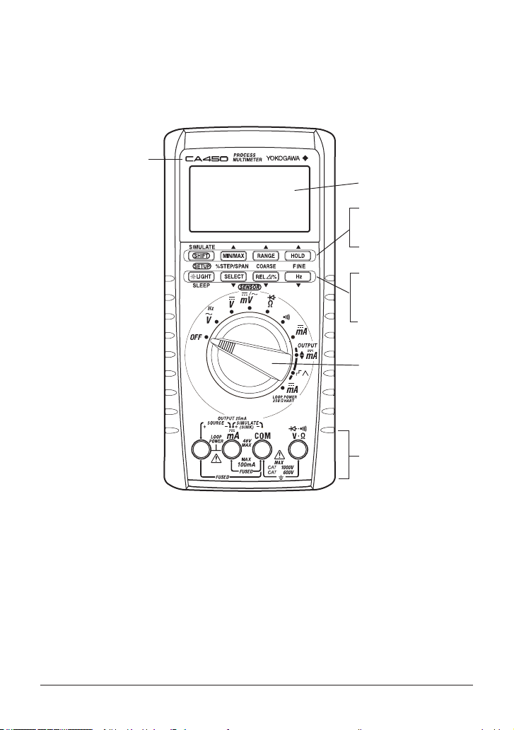
4.2 Components
Display (LCD)
Model name
Front Panel
■ CA450
SHIFT key
MIN/MAX key
RANGE key
HOLD key
LIGHT key
SELECT key
RELΔ/% key
Hz key
Function
switch
Input and
output
terminal area
11IM CA450-EN
Page 23

Blank cover
Rear Panel
(Back)
Under (hidden below)
the stand
1000V 10A CAT II
Caps of Test leads
Measurement category O (Other) DC 70V 100 mA
Serial
number
Nameplate
■ Test leads (98073)
With Caps:
1000V 10A CAT III/600V 10A CAT IV
Without Caps:
■ Lead cables (98064)
Stand
Black
Red
IM CA450-EN12
Page 24

(1) Function switch
V / Hz
V
mV / mV
Ω /
mV / mV
Ω /
Use this switch to turn the power on and off and to select the measurement mode.
Function Mode Function Mode
OFF
Turns the CA450 off. Continuity check
AC voltage measurement
and frequency measurement
DC voltage measurement
DC/AC voltage measurement
in mV and various
SENSOR modes
Resistance measurement
Diode test
OUT
PUT
DC current measurement
DC current output
Constant current output
DC current output
Current sweep output
DC current measurement
Loop power supply
If test leads or lead cables are connected to the current measurement
and output terminals, you cannot turn the function switch to
the OFF position.
(2) SELECT key
By pressing this key, you can select different measurement modes
when the function switch is at the positions listed below.
You can switch out of the selected mode by pressing the key again.
position: AC voltage mV measurement
(AC SENSOR measurement in SENSOR mode)
position:
Diode test
position:
position:
(3) RANGE key
Use this key to select the measurement range.
Fixed
AUTO
range: “Range Hold” appears on the display.
The range increases each time you press RANGE.
range:
“AUTO” appears on the display.
To select AUTO range, hold down RANGE for 1 second or longer.
The SELECT key turns the internal series resistor
for HART communication on and off.
Operation mode switching
13IM CA450-EN
Page 25
(4) HOLD key
Use this key to hold the measured values.
Press HOLD to switch between data hold, auto hold, peak hold,
and no hold (release).
(Hold modes that are not supported for the selected measurement function
are skipped.)
Data hold:
Auto hold:
Peak hold
The currently displayed measured values are held. “D•H” appears
on the display.
The measured values are automatically held according to
the operation of the test leads. “A•H” appears on the display.
The peak values are held. “P•H” appears on the display.
(5) LIGHT key
Use this key to turn the backlight on and off.
Press the key once to turn it on. Press it again to turn it off.
Use this key to control the sleep function.
During measurement or output, Hold down LIGHT for 2 seconds or longer
to put the CA450 in sleep mode. (While the CA450 is in sleep mode,
hold down the LIGHT key for 2 seconds or longer to clear sleep mode.)
(You cannot clear sleep mode immediately after the CA450 is put in sleep mode.
Wait at least 2 seconds after the CA450 is put in sleep mode before you clear it.)
(6) key
Use this key to display the measured values as relative values
(you can display the differences between values using numbers or percentages).
1: Difference display
2: Percentage difference
display
(REL%)
" " appears on the display.
" " and " % " appear on the display.
Use this key during the zero adjustment of the resistance measurement function.
With the test leads shorted, press the REL key to execute zero adjustment.
IM CA450-EN14
Page 26
(7) MIN/MAX key
Use this key to display the minimum (MIN), maximum (MAX), and
average (AVG) values within the measurement period.
When you press the key, recording starts, and “MIN,” “MAX,” and “AVG” appear
on the display.
(The AUTO OFF function is disabled.) When peak hold is enabled,
press the REL key to reset the peak value.
(8) Hz key
When the function switch is turned to , use this key to switch between
AC voltage measurement and frequency measurement.
Use this key in calibration mode to conrm the calibration value.
(9) SHIFT key
If you press SHIFT while a measurement mode is selected,
“Shift” appears on the display.
In this state, you can congure various settings by pressing the various keys.
SHIFT +
LIGHT key
SELECT key
SETUP mode
Switches from mV mode to SENSOR mode
While an output mode is selected, press SHIFT to switch between
SOURCE and SIMULATE.
15IM CA450-EN
Page 27
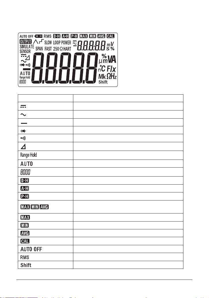
■ Display (LCD) Description
Symbol or Unit Description
Appears during DC measurement or output
Appears during AC measurement
Appears when the polarity is negative (minus)
Appears during diode test mode
Appears during continuity check mode
Appears when relative values are being displayed
Indicates that the measurement range is set to xed
Indicates that the measurement range is set to auto
Indicates the present range
Appears when data hold is enabled
Appears when auto hold is enabled
Appears when peak hold is enabled
Appears when the MIN, MAX, and AVG values
are being measured
Appears when the MAX value is being displayed
Appears when the MIN value is being displayed
Appears when the AVG value is being displayed
Appears when user calibration is being performed
Appears when the auto power-off function is enabled
Appears during rms value detection
Appears when SHIFT has been pressed
IM CA450-EN16
Page 28
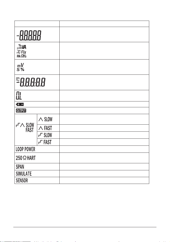
Symbol or Unit Description
Shows the main value
Shows the input or output value
A converted value is shown in SENSOR mode
Appears when the range has been exceeded
Appears when the battery voltage is low
Appears during current output
Appears in loop power supply mode
Appears in SPAN check mode
Appears when the SIMULATE operation is being performed
Appears in SENSOR mode
Indicates the main unit
Indicates the subunits
Shows the MIN, MAX, and AVG recording time
Shows the input voltage unit in SENSOR mode
Shows the subvalue
Shows the MIN, MAX, and AVG recording time
Shows the reference value during relative calculation
Shows the current sweep output or step output status
Appears during slow linear output
Appears during fast linear output
Appears during slow step output
Appears during fast step output
Appears when the internal resistor for
HART communication is on
17IM CA450-EN
Page 29
4.3 Measuring Instructions
WARNING
Note
To avoid damaging the instrument and other equipment:
• Before you start measuring, make sure that the position of the function switch
and position of the input terminals for connecting the test leads or lead cables
are appropriate for the desired mode of measurement.
(Check that they are appropriate fo
• Before you turn the function switch, remove the test leads or lead cables
from the circuit under measurement.
• Before you use this instrument or use its indications as a reference for further
procedures, make sure that the instrument functions properly when used
with a known power supply.
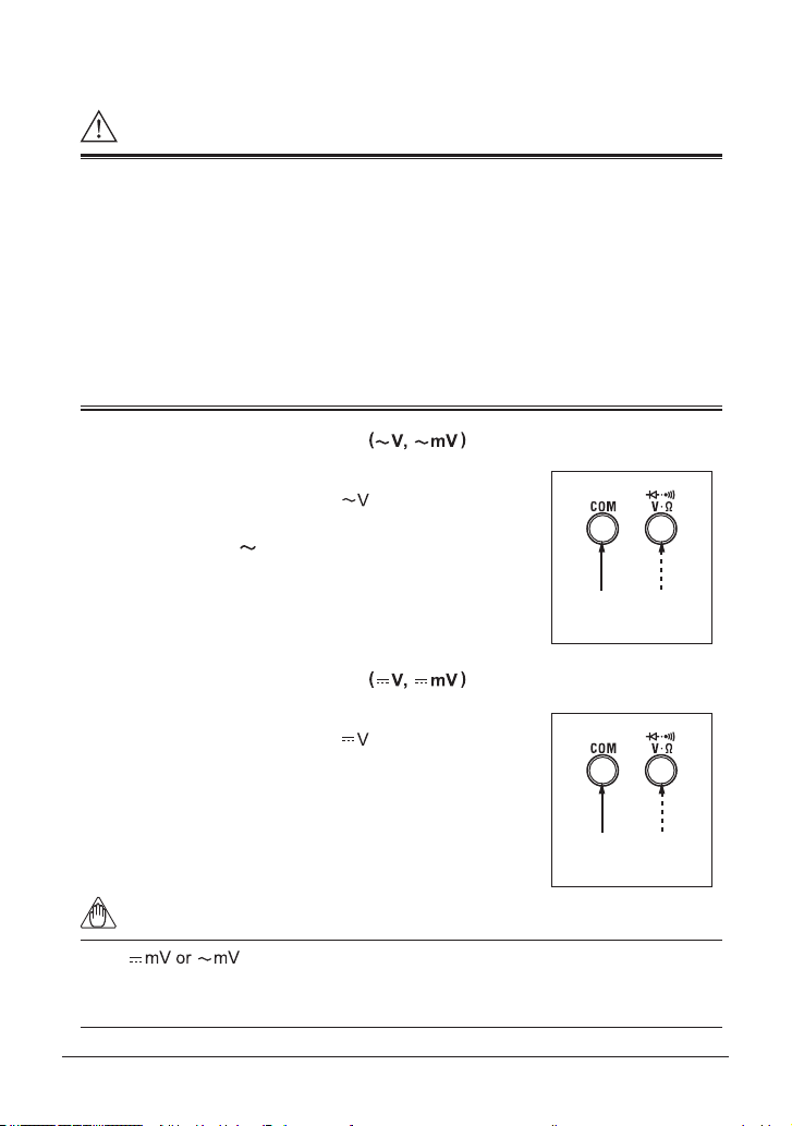
4.3.1 AC Voltage Measurement
1) Turn the function switch to the “ ” or “mV” position.
2) If you turned the function switch to “mV,”
press SELECT. (“
3) Insert the test leads into the input terminals.
4) Connect the test leads to the circuit under
measurement, and then read the value
when it stabilizes.
” is displayed.)
4.3.2 DC Voltage Measurement
r the measurement category.)
Test leads
Black Red
1) Turn the function switch to the “ ” or “mV” position.
2) Insert the test leads into the input terminals.
3) Connect the test leads to the circuit under
measurement, and then read the value
when it stabilizes.
Test leads
Black Red
If the range setting is selected and the test leads are not connected
to a circuit, the instrument will still display a value, but measurement will not be
adversely affected.
IM CA450-EN18
Page 30

4.3.3 Measuring Using Sensors (SENSOR)
DC SENSOR range
You can use this function to measure the output of a current sensor or other type of
sensor that converts its measured values into voltages, to convert the voltages
into the original measured values, and to display the converted values.
Before you perform measurement, you need to congure unit, conversion,
and other settings.
See section 4.6.2 “SENSOR Mode Input, Display, and Unit Settings.”
urn the function switch to the “mV” position.
1)
T
2) Press SHIFT+SELECT to switch to DC SENSOR mode.
To switch to AC SENSOR mode, press SELECT again.
The input voltage appears in the s
In the main display, the value converted using the settings congured in
section 4.6.2 “SENSOR Mode Input, Display, and Unit Settings.”
AC SENSOR range
3) Connect the sensor that you will use to the input terminals.
4) Read the value when it stabilizes.
To return to normal mV measurement, press SHIFT+SELECT again.
ubdisplay.
SENSOR
Example of measurement when connecting a current clamp sensor
with an input-to-output ratio of 10 mV/A
Use the setup function (see section 4.6) to congure the following settings.
Instrument input voltage: 10.0 (mV)
Converted value, decimal place: 01.00
Unit: A
If you connect the sensor after conguring the above settings,
the current clamp sensor’ s output voltage (in mV) appears in the subdisplay,
and the current detected by the current clamp sensor appears in the main display.
(You can read the values directly.)
19IM CA450-EN
Page 31

4.3.4 Resistance Measurement (Ω)
CAUTION
Note
To avoid damaging the instrument:
Before measurement, turn off the circuit under measurement so that no voltage is
applied.
1) Turn the function switch to the “Ω” position.
2) Insert the test leads into the input terminals.
3) Connect the test leads to the circuit under
measurement, and then read the value
when it stabilizes.
Test leads
Black Red
Zero adjustment for resistance
We recommend that you perform zero adjustment to obtain accurate
measurements.
After you perform steps 1) and 2) above, short the test leads,
and press the REL key.
(When zero adjustment is performed, the instrument will show a reading of 0.0 Ω.)
The zero adjustment value is used until the power is turned off.
IM CA450-EN20
Page 32

4.3.5 Continuity Check
CAUTION
CAUTION
To avoid damaging the instrument:
Before measurement, turn off the circuit under measurement so that
no voltage is applied.
1) Turn the function switch to the“
2) Insert the test leads into the input terminals.
3) Connect the test leads to the circuit under measurement
whose continuity you want to check.
If
the circuit is continuous
(less than approximately 50Ω), the buzzer sounds.
”position.
4.3.6 Diode Test
To avoid damaging the instrument:
Before measurement, turn off the circuit under measurement so that
no voltage is applied.
1) Turn the function switch to the “Ω” position.
Press SELECT to switch to diode measurement.
(
is displayed.)
2) Insert the test leads into the input terminals.
3) Connect the test leads to the diode, and then read
the value when it stabilizes.
Test leads
Black Red
Test leads
Black Red
21IM CA450-EN
Page 33

Forward-Bias Diode Test
Test leads
Forward-bias test
Reverse-bias test
Test leads
Connect the black test lead to the cathode, and connect
the red test lead to the anode.
For a silicon diode, the reading should be approximately
0.5 V.
For an LED, the reading should be approximately
1.5 V to 2.0 V.
Reverse-Bias Diode Test
Connect the black test lead to the anode, and connect
the red test lead to the cathode.
Normally, “OL” appears. If a voltage value appears,
the diode is defective.
Black
Red
Figure 1
Red Black
Figure 2
IM CA450-EN22
Page 34

4.3.7 DC Current Measurement
WARNING
Subdisplay (percentage of span)
Subdisplay (percentage of span)
Main display (30 mA range) Main display (100 mA range)
To avoid damaging the instrument and other equipment:
• Before you start measuring, make sure that the position of the function switch
and position of the input terminals for connecting the test leads are appropriate
for the desired mode of measurement.
The maximum input current for mA
measurement is 110 mA.
1) Turn the function switch to the “
2) Connect the black test lead to the COM input terminal,
and connect the red test lead to the
3) Connect the test leads to the circuit under measurement,
and then read the value when it stabilizes.
Press the RANGE key to select a range.
When the range is 4 to 20 mA
”position.
input terminal.
Test leads
Red Black
When the range is 10 to 50 mA
23IM CA450-EN
Page 35

Subdisplay: Displaying and Conguring the Span
In addition to the DC current value in the main display,
you can also display the span value as a percentage in the subdisplay.
Subdisplay for the 30 mA Range
Input Current Value
(Main display)
-33.000 mA -231.3% -165.0%
0.000 mA -25.0% 0.0%
4.000 mA 0.0% 20.0%
20.000 mA 100.0% 100.0%
30.000 mA 162.5% 200.0%
33.000 mA 181.3% 165.0%
The displayed value varies depending on the setting
(4 to 20 mA or 0 to 20 mA) made in section 4.4.4, “Current Span Setting.”
Subdisplay for the 100 mA Range
Input Current Value
(Main display)
-110.00 mA -110.0% -300.0% -220.0%
0.00 mA 0.0% -25.0% 0.0%
10.00 mA 10.0% 0.0% 20.0%
50.00 mA 50.0% 100.0% 100.0%
100.00 mA 100.0% 225.0% 200.0%
110.00 mA 110.0% 250.0% 220.0%
The displayed value varies depending on the setting
(0 to 100mA, 10 to 50mA, or 0 to 50mA) made in section 4.6.3, “Current Span Setting
for the 100 mA Range for DCmA Measurement.”
Subdisplay for the 30 mA Range
4 to 20 mA 0 to 20 mA
Subdisplay for the 100 mA Range
0 to 100 mA 10 to 50 mA 0 to 50 mA
IM CA450-EN24
Page 36

4.3.8 Loop Power Measurement
LOOP POWER
Two-wire system transmitter
Transmitter
You can use this function to measure the current that ows when a constant
voltage of 24 VDC is applied.
24 V loop measurement can be used for transmitter loop testing.
(You can connect the CA450 to the transmitter instead of connecting a transmitter
or signal conditioner.)
(signal conditioner)
4 to 20 mA
Red Black
1) Turn the function switch to the “ ” position.
(“LOOP POWER” appears on the display.)
A constant voltage of 24 VDC is output between the “SOURCE (+)” and
“SOURCE (−)” measurement terminals.
2) Connect the red test lead to “SOURCE (+)” and the black test lead to “SOURCE (−).”
3) Connect the test leads to the circuit under measurement, and then read the values
when they stabilize.
Just as in mA measurement, the main display shows the measured value,
and the subdisplay shows the value of the measured value divided by
the current span times 100 (%).
(See section 4.3.7 “DC Current Measurement.”)
Distributor
25IM CA450-EN
Page 37

4) Press SELECT to turn the internal 250 Ω series resistor for
Tip
Tip
HART communication on.
(“250ΩHART” appears on the display.)
Press SELECT again to turn the internal resistor off.
The loop power is supplied at the typical value of 24 VDC.
Depending on different conditions, such as the loop current value or
whether there is a internal series resistor,
the voltage across the terminals may be greater than 24 V.
4.3.9 Frequency Measurement (Hz)
1) Turn the function switch to the “ “ position.
2) Press the Hz key to select frequency measurement.
(The measured frequency value and unit appear in
the main display, and the measured voltage appears
in the subdisplay.)
3) Insert the test leads into the input terminals.
4) Connect the test leads to the circuit under measurement,
and then read the values when they stabilize.
Test leads
Black Red
Note that range hold and selection operations performed using the Range key
only apply to the subdisplay (measured voltages).
IM CA450-EN26
Page 38

4.3.10 Auto Hold Function
Note
The CA450 can automatically detect measured values and hold them according to
the operation of the test leads.
1) During normal measurement, press the HOLD key twice to select “A•H.”
(“A•H” appears
2) Connect the test leads to the circuit under measurement.
3)
When the measured value stabiliz
4) Remove the test leads from the circuit under measurement.
5) The measured value display is held down.
While “A•H” is displayed, you can
• You cannot use this function during DCmV or ACmV measurement
(this includes SENSOR mode), frequency measurement, or during
a continuity check.
• You cannot use this function at the same time as the relative value display
function or when the MIN, MAX, and AVG values are being recorded.
• Unstable input signals (measured values) cannot be held.
on the display.)
es, the buzzer makes a beeping sound.
repeat steps 2) through 4) as often as you want.
4.3.11 Peak Hold Function
The CA450 always detects and updates the instantaneous peak value during
DC voltage measurement (DCV).
You can determine the peak value of a waveform.
1) Set the function switch to .
2) Connect the test leads to the circuit under measurement.
3) Press the HOLD key three times to select “P•H.”
(“P•H” appears on the display, and the voltage range is xed.)
4) The peak value display is held.
5) You can reset the held peak value by pressing the MIN/MAX key.
You can hold a new peak value.
27IM CA450-EN
Page 39

Note
• Even if the polarity of the input signal (DCV) is negative (minus), as long as
the peak (change) direction is positive, the peak value can be measured.
• While the peak value is being measured, you can display relative values
based on a measured reference value.
1) Press the key while the peak is held. (“ ” is displayed.)
Main display value: The current peak value – the peak value
when the REL key was pressed
2) Press the key again. (The unit changes to ‘%’.)
Main display value: (The current peak value – the peak value
when the REL key was pressed) /the peak value when the REL key
was pressed × 100 (%)
3) To no longer show relative values, press again.
The “ ” and “%” display disappear, and the CA450 returns to the
normal peak hold mode.
You can reset the peak value by pressing MIN/MAX.
•
ou can hold a new peak value.
Y
IM CA450-EN28
Page 40

4.3.12 Relative Value Display
The CA450 can calculate and display relative values that represent the difference
or percentage from a reference value. (In this display, the range is xed.)
Difference Display
The CA450 shows the value of the measured value minus the reference value.
Measure (input) the reference val
1)
2) Press to conrm the reference value.
(“
” is displayed, and the range is held.)
Measure (input) the measured va
3)
on the measurement function.
• For DCmA measurement (including loop power measurement):
Main display value:
Subdisplay value: (Measured value – reference value)/
current span setting × 100 (%
• For measurement types other than DCmA:
Main display value:
Subdisplay value:
Percentage Difference Display (REL%)
The CA450 computes the value of (Measured value – reference value)/
reference value and displays the result as a percentage.
1)
Measure (input) the reference val
2) Press
(“ ” is displayed, and the range is held.)
3) Press again. (“%” appears.)
4)
Measure (input) the measured va
The displayed v
to conrm the reference value.
alues vary depending on the measurement function.
ue.
lues. The displayed values vary depending
Measured value – reference value
)
Measured value – reference value
Reference value
ue.
lues.
• For DCmA measurement (including loop power measurement):
Main display value: (Measured value – reference value)/
current span setting × 100 (%)
Subdisplay value: Reference value
• For measurement types other than DCmA:
Main display value: (Measured value – reference value)/
reference value × 100 (%)
Subdisplay value: Reference value
29IM CA450-EN
Page 41

4.3.13 MIN/MAX/AVG Function
Note
You can use this function to display the minimum (MIN), maximum (MAX),
and average (AVG) values within the current measurement period.
(In this display, the range is xed.)
The averaged value that is displayed is the total of the recorded data divided by
the number of recorded values.
When you press the MIN/MAX key, recording starts, and “MIN,” “MAX,” and “AVG”
appear on the display. (The AUTO OFF function is disabled.)
Recording Time
The timer starts, and the time from the start of recording is displayed as well as
the MIN/ MAX record update time.
The recorded time display shows times in the range of 0 seconds to 99 minutes,
59 seconds in units of seconds.
It shows times greater than 100 minutes in units of minutes.
To stop recording, press the HOLD key. (“D•H” appears on the display.)
Checking the Recording Time
You can check the recorded data by pressing the MIN/MAX key to switch between
the display of the current maximum (MAX), minimum (MIN), and average (AVG)
values.
To restart recording, press the HOLD key again.
To disable the MIN/MAX/AVG function, hold down MIN/MAX for 1 second or longer.
(“MAX,” “MIN,” and “AVG” disappear.)
• While recording is stopped, removing the test leads does not affect the recorded
data.
• When an out-of-range input value is recorded, the minimum or maximum value
is displayed as “OL,” and the average value data becomes inaccurate.
• When you are measuring a widely uctuating signal, set the range to contain
the maximum and minimum values so that these values are not displayed as “OL.”
IM CA450-EN30
Page 42

4.4 Output Instructions
WARNING
CAUTION
The CA450 can output DC current.
There are two output modes.
SOURCE mode: Current is supplied from the CA450.
SIMULA
voltage source.
TE mode (SINK):
There are two conguration modes.
Constant current output: The specied current is output continuously.
Current sweep output:
decreased within the specied span.
Do not apply a voltage of 48 V or greater to the output terminals.
Doing so may lead to electric shock.
Also, keep the voltage between the circuit and the ground below 48 V.
Always use the attached lead cables and lead cables.
(Check that they are appropriate for the measurement category.)
In modes other than SIMULATE mode, do not apply voltages to the output
terminals.
Mistakenly applying voltage to the output terminals could damage the internal
circuitry.
The CA450 sinks current from an external
The output current is increased and
If the mark appears while you are using the current output function,
replace the batteries.
31IM CA450-EN
Page 43

4.4.1 Constant Current Output (SOURCE mode)
1) Turn the function switch to the “ ” position.
After you turn the function switch, “OUTPUT” appears on the screen,
and the output is set to 0% of the current span setting.
(If you turn the function switch from the “
the “
” position, the output value setting and SOURCE/SIMULATE
” (current sweep) position to
setting are retained.)
2)
ULATE” is displayed, press the SHIFT key.
If “SIM
(“SIMULATE” disappears, the CA450 switches to SOURCE mode,
and current output starts.)
3) Connect the lead cables to the positive (+) and negative (–) SOURCE terminals.
4) Use the output value setting keys to set the output value.
5)
ct the lead cables to the circuit under test.
Conne
Lead cables
Red Black
Output Value
Setting Key
%STEP *
COARSE
FINE
Output Setting
(Increase and decrease)
1-step (25%) increase
▲
1-step (25%) decrease
▼
0.1 mA increase
▲
0.1 mA decrease
▼
0.001 mA increase
▲
0.001 mA decrease
▼
* For details about using the %STEP key,
see “Output Values for Each Step” and “Span Check Mode.”
IM CA450-EN32
Page 44

Tip
When the range is 4 to 20 mA
• Because the CA45 0 outputs current in SOURCE mode, it consumes more
current than in other modes.
You can keep the current consumption down in SIMULATE mode.
• Hold down the %STEP, COARSE, or FINE key to increase or decrease
each digit consecutively.
Output Values for Each Step
You can press
by one step (25%).
You can check the step value (as a percentage) in the subdisplay.
(The output current appears in the main display.)
or to increase or decrease the output
Step
(Subdisplay)
-25% 0.000 mA ---
0% 4.000 mA 0.000 mA
25% 8.000 mA 5.000 mA
50% 12.000 mA 10.000 mA
75% 16.000 mA 15.000 mA
100% 20.000 mA 20.000 mA
125% --- 25.000 mA
131.2% 25.000 mA ---
For the method for setting the current span,
see section 4.4.4, “Current Span Setting.”
Span Check Mode
You can switch the output current between 20 mA and 4 mA (or 20 mA and 0 mA)
using just the %STEP keys.
4 to 20 mA 0 to 20 mA
Output Value
33IM CA450-EN
Page 45

When you hold down or for 1 second or longer, “SPAN” appears,
Tip
CAUTION
and the CA450 enters into span check mode.
In this mode, the output switches to 100% when you press and to 0%
when you press
Setting Key Output Setting
%STEP
The COARSE (0.1 mA increase and decrease) and FINE
(0.001 mA increase and decrease) keys can also be used.
.
▲ 20.000 mA (100%)
▼
4 to 20 mA
4.000 mA (0%)
0 to 20 mA
0.000 mA (0%)
To exit span check mode, hold down
or longer again. (“SPAN” disappears.)
If the set current is 0.1 mA or more and the terminals are open, “-----” appears
in the main display, and “----” appears in the subdisplay.
or for 1 second
4.4.2 Constant Current Output (SIMULATE mode)
When the SIMULATE (SINK) function is enabled, the CA450 can sink the specied
amount of current from an external voltage source (such as a distributor) through
the SIMULATE(+) terminal, and you can use the CA450 to simulate a two-wire
system transmitter in a loop test.
(You can connect the CA450 instead of a transmitter to test a transmitter or
signal conditioner.)
• When sinking 20 mA from an external power source, keep the voltage
within the range of 15 to 48 V.
• Set the polarity of the applied voltage as shown in the following gure,
and be careful not to apply voltage in the opposite direction.
IM CA450-EN34
Page 46

(SINK)
Ttansmitter
(signal conditioner)
Two-wire system
transmitter
4 to 20 mA
Distributor
Red Black
SIMULATE
1) Turn the function switch to the “ ” position.
After you turn the function switch, “OUTPUT” appears on the screen,
and the output is set to 0% of the current span setting.
(If you turn the function switch from the “
the output value setting and SOURCE/SIMULATE setting are retained.)
2) Press the SHIFT key. “SIMULATE” appears. (Current sinking starts.)
3) Connect the lead cables to the positive (+) and negative (−) SIMULATE terminals.
(Connect the positive SIMULATE terminal to the positive terminal of the external
DCV power source. Make sure that the power source voltage is within 15 to 48 V.)
4) Just as in SOURCE mode, use the output setting keys to set the sink current value.
(To enter span check mode, hold down
or longer.)
5) Connect the lead cables to the circuit under test.
” position to the “ ” position,
or for one second
Press the SHIFT key again. “SIMULATE” disappears, and the CA450 returns to
constant current output (SOURCE) mode.
35IM CA450-EN
Page 47

Tip
Tip
If the set current is 0.1 mA or more and the terminals are open, “-----” appears
in the main display, and “----” appears in the subdisplay.
4.4.3 Current Sweep Output
You can make the output current (in SOURCE or SIMULATE mode) automatically
uctuate between 0% and 100% of the current span setting.
1) Turn the function switch to the “
After you turn the function switch, “OUTPUT” appears on the screen,
” position.
and the output starts rising from 0% of the current span setting.
(If you turn the function switch from the “
” position to the “ ” position,
the output value setting and SOURCE/SIMULATE setting are retained.)
Press the SHIFT
2)
key to select the current output mode (SOURCE or SIMULATE).
3) Press the SELECT key to select an output mode.
(When you change the output mode, the current starts rising from the value
currently being output according to the new mode.)
4) After you connect the lead cables to the appropriate terminals for the output mode
(SOURCE or SIMULATE), connect them to the circuit under test.
If you want to stop a current sweep that is being output,
turn the function switch to “
.”
(The constant current output value is set to the value of the current
being output when the switch is turned.)
Operation Mode Operation
Slow 0% to 100% to 0% in 40 seconds
Fast 0% to 100% to 0% in 15 seconds
Slow 0% to 100% to 0% in 25% steps
Each step is 15 to 60 seconds long. *
Fast 0% to 100% to 0% in 25% steps
Each step is 5 seconds long.
IM CA450-EN36
Page 48

Linear Mode Current Output
(%)
Time (s)
Span
Fast: 5 sec
Time (s)
Span
Tip
Output current
100
0
Step Mode Current Output
SlowFast
4015
Output current
100
(%)
0
Slow: 15 to 60 sec *
* In slow step mode, you can select 15, 30, 45, or 60 seconds.
See section 4.6.4, “Setting the Slow Step Time.”
37IM CA450-EN
Page 49

4.4.4 Current Span Setting
You can select one of the following two current spans.
The following two percentage displays vary depending on the selected range:
the output current value and the measured current value for mA measurement mode
in the 30 mA range.
Current Span
Setting
4 to 20 mA 4.000 mA 20.000 mA
0 to 20 mA 0.000 mA 20.000 mA ---
Output Current and Measured Current
(30 mA range)
When the display is 0% When the display is 100%
Notes
Factory
default
You can use the following method to set (change) the current span.
1) Turn the function switch to the “OFF” position, or put the CA450 into sleep mode.
2)
While holding d
If the CA450 is in sleep mode, hold down the RANGE and LIGHT keys
for 2 seconds or longer.
3)
After all the LCD elements appea
4) After setting the current span, turn the function switch to the "OFF" position,
or put the CA450 into sleep mode.
If the current span was set to 4 to 20 mA, this operation changes it to 0 to 20 mA.
If the current span was set to 0 to 20 mA, this operation sets it to 4 to 20 mA.
The setting you make remains valid until you change it.
own the RANGE key, turn the function switch to any position.
r and then disappear, release the key.
4.5 Auto Power-Off (Sleep) Function
When the Auto Power-Off Function Is Enabled
“AUTO OFF” appears.
• The CA450 has an auto power-off function that automatically switches itself to
sleep mode 20 minutes after the last key operation.
The buzzer makes a beeping sound approximately 30 seconds before
the CA450 enters sleep mode. (This period is referred to as the warning period.)
• If you press a key or switch during the warning period, the time before
auto power-off is extended.
• You can clear sleep mode by turning the function switch to the OFF position,
waiting 1 second or longer, and then turning the switch to any position
other than OFF. (You canalso hold down the LIGHT key for 2 seconds
or longer to clear sleep mode.)
IM CA450-EN38
Page 50

When the Auto Power-Off Function Is Disabled
Note
1) Turn the function switch to the “OFF” position, or put the CA450 into sleep mode.
2) While holding down HOLD, turn the function switch to any position.
If the CA450 is in sleep mode, ho
for 2 seconds or longer.
The auto power-off function is disabled, and “AUTO OFF” disappears.
Restoring the Auto Power-Off Function
When the function switch is set to OFF or when the CA450 enters sleep mode,
the auto power-off function is restored.
(When the power is turned on or when sleep mode is cleared, “AUTO OFF” appears.)
ld down the HOLD and LIGHT keys
4.6 Setup Function
You can use the setup function to:
1. Turn the buzzer on and off.
2. Congure SENSOR mode input, display, and unit settings.
3. Set the current range of the 100 mA range for DCmA measurement.
4. Set the slow step time.
5. Return the settings to their factory default values.
1) Press the SHIFT key. “Shift” appears on the display.
While “Shift” is displayed, press th
2)
After “SEtUP” appears, the screen for turning the buzzer on and off appears.
3) The setting to congure changes each time you press the LIGHT or SHIFT key.
4) To change a setting, use the ▲ (RANGE) and ▼ (REL) keys.
5) To save (conrm) a setting, press the HOLD key. (“SEt” appears,
the setting is saved, and the setting item is redisplayed.)
6) To return to normal measurement from setup mode, hold down the LIGHT key
for 1 second or longer.
e LIGHT key to switch to setup mode.
• To cancel a setting, press the LIGHT key for 1 second or longer without pressing
the HOLD key, or use the function switch to turn the power off.
• You cannot enter setup mode from one of the current output modes
(constant current output or current sweep output mode).
39IM CA450-EN
Page 51

4.6.1 Turning the Buzzer On and Off
:ON
You can turn the buzzer (beeping) sound on and off.
Even if you turn the buzzer off, it will sound when it is performing important functions
such asthose listed below.
• Continuity check buzzer
• Excess input alarm buzzer
• Auto power-off warning buzzer
1) Press the LIGHT or SHIFT key to display “bEEP.”
urn the buzzer on and off in the subdisplay. The initial setting is on.)
(T
:OFF
HOLD
2) Use the ▲ (RANGE) and ▼ (REL) keys to select ON or OFF.
3)
Press the HOLD key to save the setting.
(After “SEt” appears, “bEEP” will appear again.)
4) To return to normal measurement from setup mode, hold down the LIGHT key
for 1 second or longer.
IM CA450-EN40
Page 52

4.6.2 SENSOR Mode Input, Display, and Unit Settings
Subdisplay 4
Main display 4
Subdisplay 1
Main unit
Main decimal place
10 mV
6
660 mV
Display
Input
For SENSOR mode (mV position on the function switch), you can set
the input voltage and the corresponding main display and unit for that input voltage.
1) Press the LIGHT or SHIFT key to display the screen shown below.
The parameter that can be changed blinks.
Main display 1
Keep pressing the LIGHT key to switch between the following parameters.
Subdis
2) Use the ▲ (RANGE) and ▼ (REL) keys to set the various values,
3) Press the HOLD key to save the settings.
(After “SEt” appears, the setting screen will appear again.)
4) To return to normal measurement from setup mode,
<Settings>
Subdisplay value: 000.0 to 999.9
Main display value: 0000 to 9999
Main display decimal place: XXXX, X.XXX, XX.XX, or XXX.X
Main display unit: A, mA, μA, °C, MΩ, kΩ, Ω, kHz, Hz, μF, nF, %, lx, no unit, V, or mV
<Example>
For a current clamp sensor with an input-to-output ratio
of 10 mV/A, set the subdisplay to 10.0 mV,
and set the main display (value, decimal place, and unit)
to 01.00 A.
With these settings, a maximum input of 660.0 mV
will be displayed as 66.00 A.
play 4, subdisplay 3, subdisplay 2, subdisplay 1, main display 4,
main display 3,
(You can press the SHIFT key to switch parameters in the opposite direction.)
the decimal place, and the unit.
hold down the LIGHT key for 1 second or longer.
main display 2, main display 1, main decimal place, and main unit
6 A
1 A
0
41IM CA450-EN
Page 53

4.6.3 Current Span Setting for the 100 mA Range for DCmA Measurement
When you select the 100 mA range in DCmA measurement mode ( ),
you can change the current span (0 to 100 mA, 10 to 50 mA, or 0 to 50 mA).
Input Current Value
(Main display)
-110.00 mA -110.0% -300.0% -220.0%
0.00 mA 0.0% -25.0% 0.0%
10.00 mA 10.0% 0.0% 20.0%
50.00 mA 50.0% 100.0% 100.0%
100.00 mA 100.0% 225.0% 200.0%
110.00 mA 110.0% 250.0% 220.0%
1)
Press the LIGHT
(The selected current span appears in the subdisplay.
The default span is 0 to 100 mA.)
2) Use ▲ (RANGE) and ▼ (REL) to select 0 to 100 mA, 10 to 50 mA, or 0 to 50 mA.
Press the HOLD key to save the setting.
3)
(After “SEt” appears, “SPAn” will appear again.)
4) To return to normal measurement from setup mode,
hold down the LIGHT key for 1 second or longer.
0 to 100 mA 10 to 50 mA 0 to 50 mA
or SHIFT key to display “SPAn.”
Subdisplay for the 100 mA Range
HOLD
IM CA450-EN42
Page 54

4.6.4 Setting the Slow Step Time
If you select slow step mode for current sweep output,
you can select the hold time (in seconds) of each step.
1) Press the LIGHT or SHIFT key to display “t.Int.”
HOLD
2) Use ▲ (RANGE) and ▼ (REL) to select 15s, 30s, 45s, or 60s.
3)
Press the HOLD key to save the setting.
(After “SEt” appears, “t.lnt” will appear again.)
4) To return to normal measurement from setup mode,
hold down the LIGHT key for 1 second or longer.
4.6.5 Returning the Settings to Their Factory Default Values
You can reset all the items that you have changed (set) in setup mode
to their factory default values.
1) Press the LIGHT or SHIFT key to display the screen for initialization,
which shows “dEF.”
HOLD
2) The settings return to their default values when you press the HOLD key.
(After “donE” appears, “dEF” will appear again.)
3) To return to normal measurement from setup mode,
hold down the LIGHT key for 1 second or longer.
Initial Settings (Default Values) for the Setting Items
Setting Item Initial Setting
Buzzer sound ON
1.
SENSOR mode Subdisplay 10.0
2.
Main display 01.00
Unit A
The current span of the 100 mA range for
3.
DCmA measurement
Slow step time setting 15 sec
4.
0 to 100 mA
43IM CA450-EN
Page 55

4.7 Additional Power-on Functions
Hold one of the keys below, and turn the function switch from OFF to any position to
congure various functions.
(If the CA450 is in sleep mode, hold down one of the keys below and
the LIGHT key for 2 seconds or longer to congure various functions.)
Key Congured Function Details
RANGE
SELECT
HOLD The auto power-off function is disabled.
Current output and measurement (30 mA range) span
(0 to 20 mA, 4 to 20 mA)
All the LCD elements appear
(only while the SELECT key is pressed).
Section
4.4.4
Section
4.7.1
Section
4.5
HOLD +
SELECT + RANGE Calibration function
The calibration data is returned to its factory default. ---
Chapter
5
4.7.1 Making All the LCD Elements Appear
If you hold down the SELECT key and turn the function switch from OFF
to any position, all the LCD segments and marks are displayed.
The LCD segments and marks are only displayed while the SELECT key is held.
(If the CA450 is in sleep mode, hold down the SELECT and LIGHT keys
for 2 seconds or longer to turn the entire LCD on.)
IM CA450-EN44
Page 56

5. User Calibration Function
CAUTION
We recommend that you calibrate the instrument once a year to maintain its accuracy
(high accuracy).
You can use the user calibration function to perform calibration.
To avoid electrical shock:
• Make sure that specialized technicians calibrate the instrument using
the proper equipment.
• To connect the CA450 to a signal generator (reference device),
use the test leads and lead cables that come with the reference device.
• Be sure to read the reference device’s instruction manual before
you calibrate the CA450.
• When you switch measurement modes during calibration,
be sure to remove the test leads and lead cables rst,
and then change the mode and terminal locations.
Calibration Conditions
Reference device: Use a reference device that fully satises
the accuracy of the CA450.
DC voltage and current generator or
digital multimeter (DMM)
Environment: Temperature: 23 ± 5°C,
Humidity: 45 to 75% RH (no condensation)
Before you perform calibration,
leave the CA450 in the environment described
above for 30 minutes or more.
45IM CA450-EN
Page 57

5.1 Calibrating Measurements
Calibration mode
Calibration point
Note
(CAL)
Subdisplay
Main display
Masured value
Perform calibration according to Table 1.
1) While holding down the SELECT and RANGE keys, turn the function switch
from the OFF position to the ACV position.
The CA450 will start in “calibration mode.” (The “CAL” segment will be visible.)
If the CA450 is in sleep mode, hold down the SELECT, RANGE, and
LIGHT keys for 2 seconds or longer to start the CA450 in calibration mode.
2) Use the test leads to connect the CA450 to the reference device.
3)
From the reference device, apply
The calibration point appears in the subdisplay.
4) Press the Hz key to conrm the value.
Press the calibration conrmation key after the reference device’s value stabilizes.
5) To calibrate other ranges, press the RANGE key to switch the range,
check the function switch and the input terminals, refer to Table 1,
and perform steps 3) and 4) again.
To perform peak hold and loop power calibration, see section 5.1.1,
“Peak Hold Calibration,” and section 5.1.2, “LOOP POWER calibration.”
6) To end calibration, turn the function switch off.
the values in Table 1.
You cannot calibrate the continuity check. Even in calibration mode,
normal measurement is performed.
(Keys other than RANGE and SELECT cannot be used.)
IM CA450-EN46
Page 58

Table 1 Calibration Table (Measurements)
Function Range Calibration Point (Input value)
AC voltage measurement
6.000 V 6.000 V
60.00 V 60.00 V
600.0 V 600.0 V
1000 V 1000 V
DC voltage measurement
6.000 V 6.000 V
60.00 V 60.00 V
600.0 V 600.0 V
1000 V 1000 V
DC voltage measurement
600 mV 600.0 mV
[ 50.00/60.00 Hz ]
[ 50.00/60.00 Hz ]
[ 50.00/60.00 Hz ]
[ 50.00/60.00 Hz *1 ]
AC voltage measurement
Diode test
Resistance measurement
600 mV 600.0 mV
2 V 2.000 V
600.0 Ω 600.0 Ω
6.000 kΩ 6.000 kΩ
60.00 kΩ 60.00 kΩ
600.0 kΩ 600.0 kΩ
6.000 MΩ 6.000 MΩ
60.00 MΩ 40.00 MΩ
DC voltage measurement
30.000 mADC 30.000 mA
100.00 mADC 100.00 mA
*1 If the power supply frequency is 50 Hz, calibrate using 60.00 Hz.
If the power supply frequency is 60 Hz, calibrate using 50.00 Hz.
47IM CA450-EN
Page 59

5.1.1 Peak Hold Calibration
1) In calibration mode (when the “CAL” segment is displayed),
turn the function switch to the
Press the HOLD key to enable pe
2)
3) Use the test leads to connect the CA450 to the reference device.
From the reference device, apply
4)
The calibration
You can clear the peak value by pressing the MIN/MAX key.
Press the Hz key to conrm the value.
5)
6)
From the reference device, apply the value under Full Scale in Table 2.
The calibration
Y
ou can clear the peak value by pressing the MIN/MAX key.
7) Press the Hz key to conrm the value.
T
o end calibration, turn the function switch off.
8)
point appears in the subdisplay.
point appears in the subdisplay.
position.
ak hold mode.
the value under ZERO in Table 2.
Table 2
Calibratio
Function Range
DCV
peak hold
n Table (Peak Hold)
6.000 V 0 V 6.000 V
Calibration Point (Input value)
ZERO +Full Scale
Condition
---
5.1.2 Loop Power Calibration
1) In calibration mode (when the “CAL” segment is displayed),
turn the function switch to the LOOP POWER position.
2) Connect the CA450 to the reference device as shown in the diagram.
3) Set the reference device (the sink) to -30.000 mA.
The calibration point appears in the subdisplay.
4) Adjust the reference device, which was set to -30.000 mA in the previous step,
so that the DMM display value (measured value) is 3.0000 V.
5) Press the Hz key to conrm the value.
6) To end calibration, turn the function switch off.
Table 3 Calibration Table (Loop Power)
Function Range Calibration Point
LOOP POWER 30.000 mA DC 30.000 mA 3.0000 V
DMM Display (Measured)
Value
IM CA450-EN48
Page 60

Connection Diagram (Loop power)
LOOP POWER
Digital multimeter
Second decimal place Fourth decimal place
Up to the third decimal place
Calibration mode
(CAL)
Subdisplay
Calibration
point
Main display
Measured value
5.2 Calibrating Output
Load
510 Ω/1 W
100 Ω
Red
Black
Subdisplay
Fourth decimal place
Main display
(DMM)
H (V)
3.0000 V
L
H
-30.000 mA
L
DC voltage and
current generator
(Sink function)
Perform calibration according to Table 4.
1) While holding down the SELECT and RANGE keys, turn the function switch
from the OFF position to the
2) Connect the CA450 to the reference device as shown in the diagram.
3) Start +5% calibration:
In the main display and the subdisplay, 0.0000 mA appears.
(The display in the subdisplay shows the value up to the fourth decimal place.)
position. (The “CAL” segment will be visible.)
49IM CA450-EN
Page 61

4) Use , , COARSE▲, and COARSE▼ to adjust the value
Note
that appears in the main display and the subdisplay so that it is the same as
the value read by the multimeter connected to the CA450.
You can use and to adjust the second decimal place
(values above the second decimal place are also affected), and
you can use COARSE▲ and COARSE▼ to adjust the fourth decimal place
(the third decimal place is also affected).
After you have nished adjusting
5)
the value, press the Hz key to conrm it.
6) Start full scale calibration:
In the main disp
lay and the subdisplay, 20.0000 mA appears.
(The display in the subdisplay shows the value up to the fourth decimal place.)
7) Use , , COARSE▲, and COARSE▼ to adjust the value
that appears in the main display and the subdisplay so that it is the same as
the value read by the multimeter connected to the CA450.
You can use and to adjust the second decimal place,
and you can use COARSE▲ and COARSE▼ to adjust the fourth decimal place.
8) After you have nished adjusting the value, press the Hz key to conrm it.
The calibrated
(The previous calibration data is o
T
9)
o stop calibration, turn the function switch off.
range value is computed and saved in the internal memory.
verwritten.)
10) Perform steps 2) through 7) for the SOURCE and SIMULATE output modes.
You cannot calibrate current sweep output. Even in calibration mode,
normal output is performed.
(Keys other than SHIFT and SELECT cannot be used.)
Table 4 Calibration Table (Output)
Function
Constant current
output
Output
Direction
SOURCE 1.0000 mA 20.0000 mA ---
SIMULATE 1.0000 mA 20.0000 mA
* Adjust at 5% of the range.
Calibration Point
±5% * ±Full Scale
Condition
28 V
external voltage
IM CA450-EN50
Page 62

Connection Diagram (SOURCE, SIMULATE)
(SINK)
SOURCE
Digital multimeter
Digital multimeter
current generator
Red
Black
(DMM)
I (A)
L
Red
Black
(DMM)
I (A)
L
H
L
DC voltage and
SIMULATE
5.3 What to Check after Calibration
After you have nished calibrating the CA450, make sure (through inspection)
that the calibration has been performed correctly and that the calibration values
have been saved to the memory.
Inspection Method
After calibration has nished, turn off the CA450.
Then, turn on the CA450, and check the calibration in the normal output and
measurement modes (not calibration mode).
Use the reference device that you used for calibration to check the calibration.
(Refer to the calibration points.)
51IM CA450-EN
Page 63

6. Communication
Note
USB adapter
CA450
You can congure the CA450 and check its settings, measured values,
and other information from a PC.
Through the use of a communication adapter, the CA450 can communicate
with a PC through USB.
6.1 Cable Connection and Interface Specications
Cable Connection
Model 92015: Communication Package (sold separately)
Remove the blank cover on the back of the CA450, and connect a USB adapter.
(USB adapter
, USB cable and software)
USB
cable
Stand
Conguring the RS232 Interface
Baudrate: 9600 bps
Parity: None
Stop bits:
Data length: 8 bits
Flow control: None
Terminator: CrLf only
2 bits
IM CA450-EN52
Page 64

6.2 Communication Commands
Item
Data
acquisition
Measurement
settings
Output
settings
Command
OD
MF
MR
HD
SM
DI
IO
MH
RP
MI
MC
CC
RG
SF
SR
SD
AS
UP
DW
SP
UQ
DQ
RA
SS
Description
Outputs measured values
Normal
O O
Cal.
Queries the measurement function O X
Sets or queries the measurement range O O
Sets or queries the measured-value-display
hold function
O O
Sets or queries SENSOR mode O X
Switches or queries diode test mode O O
Sets or queries whether the internal resistor for
HART communication is on or off
O X
Sets or queries frequency measurement O X
Sets or queries the RELΔ/% display O X
Sets or queries the MIN/MAX/AVG function O X
Switches or queries the MIN/MAX/AVG function
O X
Sets or queries whether the measurement
mode is DCmV or ACmV (DC sensor or AC
O O
sensor in SENSOR mode)
Sets or queries the auto range and range hold
settings
O X
Queries the output function O X
Sets or queries the output range (span) O O
Sets or queries the output value O X
Sets or queries whether the current output
function is set to SOURCE or SIMULATE mode
Increases the m
th
digit of the output value by 1 O X
Decreases the mth digit of the output value by 1
O X
O X
Sets or queries SPAN check mode O X
Increases the output value by one step or sets
the output value to 100%
Decreases the output value by one step or sets
the output value to 0%
O X
O X
Sets or queries the current sweep output O O
Sets or queries the slow step time O X
53IM CA450-EN
Page 65

Item
Calibration
Other
commands
Command
SY
CL
CP
CMF
CS
CSF
CR
CD
CW
OE
OS
ESC C/
RC
ESC S
H
IM
BL
HC
BZ
MP
SI
ST
SL
SU
Description
Sets or queries whether the mode is normal
mode or calibration mode
Queries the calibration item X O
Sets the calibration point X O
Queries the measurement mode being
calibrated
Confirms the measurement calibration value X O
Queries the output mode being calibrated X O
Sets the output calibration value X O
Confirms the output calibration value X O
Saves the calibration value X O
Outputs error data O O
Outputs setup data O X
Initializes setup data
Outputs the status byte O O
Sets or queries whether a header is attached to
the output data (OD)
Sets or queries whether the bits in the status
byte are detected or masked
Sets or queries whether the backlight is on or off
Resets the peak hold value O X
Sets or queries whether the buzzer is on or off O X
Sets or queries the span setting for the 100 mA
range for DCmA measurement
Sets or queries the input voltage value for
SENSOR mode
Sets or queries the converted value for
SENSOR mode
Sets or queries the decimal place for SENSOR
mode
Sets or queries the unit for SENSOR mode O X
Normal
O O
X O
O X
O O
O O
O X
O X
O X
O X
O X
Cal.
IM CA450-EN54
Page 66

6.3 Detailed Command Descriptions
Conguration and Control
Command: The format for sending the command.
Answer: The format of replies to commands, such as configuration and
control commands, that are not queries for information.
(Some commands do not receive any reply.)
When an error occurs, the same error message that appears on the LCD
(“ERRm,” where m is the error number) is returned.
Queries
Command: The format for sending the command.
Return: The format of replies to commands that are queries for information.
Mode Conditions
Normal: The command can be used during normal measurement and output.
Cal.:
The other conditions for each command are listed in section 6.5, “Communication
Command
The command can be used during user calibration (see chapter 5).
Validity Table.”
AS
BL
Sets or queries whether the current output function is set to
SOURCE or SIMULATE mode
Command = ASm<CRLF> -> Answer = ASm<CRLF>
Command = AS?<CRLF> -> Return = ASm<CRLF>
Parameters
m = 0: SOURCE (default)
1: SIMULATE (SINK)
This command returns ERR13 when the CA450 is in constant
current output mode or current sweep output mode.
Sets or queries whether the backlight is on or off
Command = BLm<CRLF> -> Answer = BLm<CRLF>
Command = BL?<CRLF> -> Return = BLm<CRLF>
Parameters
m = 0: Off (default)
1: On
Norma
O X
Norma
O X
l Cal.
l Cal.
55IM CA450-EN
Page 67

BZ
Sets or queries whether the buzzer is on or off
Command = BZm<CRLF> -> Answer = BZm<CRLF>
Command = BZ?<CRLF> -> Return = BZm<CRLF>
Parameters
m = 0: OFF
1: On (default)
Normal
O X
Cal.
CC
CD
CL
Sets or queries whether the measurement mode is DCmV or
ACmV
Command = CCm<CRLF> -> Answer = CCm<CRLF>
Command = CC?<CRLF> -> Return = CCm<CRLF>
Parameters
m = 0: DCmV measurement (default)
1: ACmV measurement
In SENSOR mode
m = 0: DC sensor measurement (default)
1: AC sensor measurement
If the measurement mode is neither DCmV nor ACmV, ERR13
is returned.
Confirms the output calibration value
Command = CD<CRLF> -> Answer = CD<CRLF>
In output calibration mode, the current output settings are
used as the output calibration values for the currently selected
function, range, and calibration point (+FS, +5%, -FS, or -5%).
If the CA450 is in a measurement mode, ERR13 is returned.
Queries the calibration item
Command = CL?<CRLF> -> Return = CLm<CRLF>
Parameters
m = 3: Output calibration
4: Measurement calibration
Norma
O O
Norma
X O
Normal
X O
l Cal.
l Cal.
Cal.
IM CA450-EN56
Page 68

CMF
Queries the measurement mode being calibrated
Command = CMF?<CRLF> -> Return = CMFm<CRLF>
Parameters
m = 0: DCV
2: Ω
5: Hz
7: ACV
8: DCmV
9: ACmV
10: Diode test
11: Continuity check
12: DCmA
13: LOOP POWER
If the CA450 is in constant current output, current sweep
output, or continuity check function, ERR13 is returned.
Normal
X O
Cal.
CP
Sets the calibration point
Command = CPm<CRLF> -> Answer = CPm<CRLF>
Parameters
m = 0:
1:
2: –FS calibration
3: –5% calib
–FS calibration and –5% calibration are used to calibrate the
SIMULATE output mode.
If –FS calibration or –5% calibration is specified in
measurement mode, ERR13 is returned.
+FS calibration
Peak hold
calibration
zero calibration or +5% output
ration
Normal
X O
Cal.
57IM CA450-EN
Page 69

CR
Sets the output calibration value
Command = CRm<CRLF> -> Answer = CRm<CRLF>
Command = CR?<CRLF> -> Return = CRm<CRLF>
Parameters
m = 18.0000 to 22.0000 for ±FS calibration
m = 0.9600 to 1.0400 for ±5% calibration
Normal
X O
Cal.
CS
CSF
CW
Confirms the measurement calibration value
Command = CS<CRLF> -> Answer = CS<CRLF>
In measurement calibration mode, the current measured values
are used as the measurement calibration values for the currently
selected function, range, and calibration point (+FS or +0).
If the CA450 is in an output mode, ERR13 is returned.
Queries the output mode being calibrated
Command = CSF?<CRLF> -> Return = CSFm<CRLF>
Parameters
m = 14: Constant current output
15: Current sweep output
If the CA450 is in a measurement mode, ERR13 is returned.
Saves the calibration value
Command = CW<CRLF> -> Answer = CW,OK<CRLF>
(normal completion)
Saves the data after a mode or range is calibrated. If you turn
off the CA450 without executing this command, the calibrations
made immediately before are discarded.
Normal
X O
Normal
X O
Norma
X O
Cal.
Cal.
l Cal.
IM CA450-EN58
Page 70

DI
Switches or queries diode test mode
Command = DIm<CRLF> -> Answer = DIm<CRLF>
Command = DI?<CRLF> -> Return = DIm<CRLF>
Parameters
m = 0: Resistance measurement (default)
1: Diode test
If the mode is neither Ω nor diode test, ERR13 is returned.
Norma
O O
l Cal.
DQ
DW
Decreases the output value by one step or sets the output
value to 0%
Command = DQ<CRLF> -> Answer = DQ,OK<CRLF>
Decreases the output value by one step (25%).
Sets the output value to 0% of the span in span check mode.
If the CA450 is in any mode other than constant current output
mode, ERR13 is returned.
Decreases the m
th
digit of the output value by 1
Command = DWm<CRLF> -> Answer = DW,OK<CRLF>
Parameters
m = 1 to 5 (1 is the least significant digit while 5 is the most
significant digit)
If the CA450 is in any function other than constant current
output function, ERR13 is returned.
If the CA450 is in span check mode, ERR13 is returned.
Normal
O X
Normal
O X
Cal.
Cal.
59IM CA450-EN
Page 71

ESC C/
RC
Initializes setup data
("ESC" = ASCII 0x1B)
Command = ESC C<CRLF>
or
Command = RC<CRLF>
However, when this command is used to initialize the settings:
The output current span setting (0 to 20 mA or 4 to 20 mA) is
not initialized.
Normal
O X
Cal.
ESC S
H
HC
Outputs the status byte
("ESC" = ASCII 0x1B)
Command = ESC S<CRLF> -> Answer = m<CRLF>
Outputs the status byte (as a decimal number).
See section 6.6, “Status Byte Format.”
Sets or queries whether a header is attached to the output data
(OD)
Command = Hm<CRLF> -> Answer = Hm<CRLF>
Command = H?<CRLF> -> Return = Hm<CRLF>
Parameters
m = 0:
1: Header is
The changed setting is valid until the power is turned off.
Resets the peak hold value
Command = HC<CRLF> -> Answer = HC,OK<CRLF>
When peak hold is not enabled, ERR13 is returned.
Header is
not attached. (default)
attached.
Normal
O O
Norma
O O
Normal
O X
Cal.
l Cal.
Cal.
IM CA450-EN60
Page 72

HD
Sets or queries the measured-value-display hold function
Command = HDm<CRLF> -> Answer = HDm<CRLF>
Command = HD?<CRLF> -> Return = HDm<CRLF>
Parameters
m = 0: Display update enabled (default)
1: Data hold
2: Auto hold
3: Peak hold
• If the CA450 is in an output mode, ERR13 is returned.
• During MIN/MAX measurement, if HD1 is sent, recording and
the updating of the display of the elapsed time are stopped.
If HD0 is sent, recording and the updating of the display of
the elapsed time are resumed.
• If HD1 is sent while peak hold is enabled, ERR13 is returned.
• To clear peak hold, use the HC command.
* During calibration, only the HD3 command, which switches the mode
so that peak hold calibration can
be performed, is valid.
Normal
O O
Cal.
*
61IM CA450-EN
Page 73

IM
Sets or queries whether the bits in the status byte are detected
or masked
Command = IMm<CRLF> -> Answer = IMm<CRLF>
Command = IM?<CRLF> -> Return = IMm<CRLF>
Sets whether each of the bits in the status byte is detected or
masked. (Querying is performed using the ESC S command.
See section 6.6.)
If you specify IM0, all the bits are masked. If you specify IM63,
all the data bits reflect the current status.
Parameter
m = 0 to 63
1: bit0 (measurement completion) is detected
2: bit1 (output adjustment completion) is detected
4: bit2 (syntax error) is detected
8: bit3 (overrange) is detected
16: bit4 (24 V loop output error) is detected
32: bit5 (output error) is detected
(Bits 6 and 7 of the status byte are fixed bits.)
The default is m = 63 (no masking)
Norma
O O
l Cal.
IO
Sets or queries whether the internal resistor for HART
communication is on or off
Command = IOm<CRLF> -> Answer = IOm<CRLF>
Command = IO?<CRLF> -> Return = IOm<CRLF>
Parameters
m = 0: 250 Ω resistor off (default)
1: 250 Ω resistor on
If the CA450 is in any mode other than loop power
measurement mode, ERR13 is returned.
Normal
O X
IM CA450-EN62
Cal.
Page 74

MC
Switches or queries the MIN/MAX/AVG function
Command = MCm<CRLF> -> Answer = MCm<CRLF>
Command = MC?<CRLF> -> Return = MCm<CRLF>
Parameters
m = 0: Measured value display (default)
1: MAX value display
2: MIN value display
3: AVG value display
If MIN/MAX/AVG recording is disabled, ERR13 is returned.
Normal
O X
Cal.
MF
MH
Queries the measurement function
Command = MF?<CRLF> -> Return = MFm<CRLF>
Parameters
m = 0: DCV
2: Ω
5: Hz
ACV
7:
DCmV
8:
ACmV
9:
10: Diode tes
1:
1
12:
13: LOOP
Switches or queries frequency measurement
Command = MHm<CRLF> -> Answer = MHm<CRLF>
Command = MH?<CRLF> -> Return = MHm<CRLF>
Parameters
m = 0: ACV measurement (default)
1: Frequency measurement
If the CA450 is in any mode other than ACV mode, ERR13 is
returned.
Continuity
DCmA
t
check
POWER
Norma
O X
Norma
O X
l Cal.
l Cal.
63IM CA450-EN
Page 75

MI
Sets or queries the MIN/MAX/AVG function
Command = MIm<CRLF> -> Answer = MIm<CRLF>
Command = MI?<CRLF> -> Return = MIm<CRLF>
Parameters
m = 0: MIN/MAX/AVG recording is disabled (default)
1: MIN/MAX/AVG recording starts
If the CA450 is in an output mode, ERR13 is returned.
Normal
O X
Cal.
MP
Sets or queries the span setting for the 100 mA range for
DCmA measurement
Command = MPm<CRLF> -> Answer = MPm<CRLF>
Command = MP?<CRLF> -> Return = MPm<CRLF>
Parameters
m = 0: 0 to 100 mA (default)
1: 10 to 50 mA
2: 0 to 50 mA
If the CA450 is in an output mode, ERR13 is returned.
The changed setting is valid until it is changed again.
Normal
O X
Cal.
IM CA450-EN64
Page 76

MR
Sets or queries the measurement range
Command = MRm<CRLF> -> Answer = MRm<CRLF>
Command = MR?<CRLF> -> Return = MRm<CRLF>
Parameters
[DCV] m = 1: 6 V
3: 60 V
4: 600 V
5: 1000 V
[DCA] m = 0: 30 mA
1: 100 mA
[ACV] m = 0: 6 V
1: 60 V
2: 600 V
3: 1000 V
[Ω] m = 0: 600 Ω
1: 6 kΩ
2: 60 kΩ
3: 600 kΩ
[DCmV] m =
[ACmV] m =
[Diode test] m =
[Continuity check] m = 0: 600 Ω
[LOOP
POWER] m = 0:
4: 6 MΩ
5: 60 MΩ
0: 600 mV
0: 600 mV
0: 2 V
30 mA
Norma
O O
l Cal.
65IM CA450-EN
Page 77

OD
Outputs measured values
Command = OD<CRLF> -> Return = abbcsddddddeee<CRLF>
Parameters
Header (4 bytes)*
a = V: voltage, A: current, O: resistance, T: temperature,
F: frequency, S: SENSOR mode
bb = DC: direct current, AC: alternating current,
R3: resistance measurement
c = N: normal, O: overrange, E: no data, B: burnout
* The header will not appear if you specify 0 (no header) in
the H command.
Data Area (10 bytes)
s (sign) = _: plus or –: minus (_ represents a space)
dddddd = measured value (6 digits)
eee = E+0, E+3, E–3, E+6, E–6
(For overrange, no data, and burnout, ddddddeee =
_99999.E+6)
Normal
Cal.
O O
OE
Outputs error data
Command = OE<CRLF> -> Return = ERRm<CRLF>
Outputs the most recent output error.
After a value is returned, the saved error number is overwritten
with ‘ERR00<CRLF>’.
Even if there is no error, ‘ERR00<CRLF>’ is returned.
Parameters
m = Error code
See section 6.4, “List of Errors.”
Normal
O O
IM CA450-EN66
Cal.
Page 78

OS
Outputs setup data
Command = OS<CRLF> -> Return = Measure a<CRLF>
Function b<CRLF>
Range c<CRLF>
Source d<CRLF>
Function e<CRLF>
Range f<CRLF>
Data g<CRLF>
24V Output h<CRLF>
Light i<CRLF>
Charge j<CRLF>
Parameters
a (measurement) = ON or OFF
b (measurement function) =
c (measurement range) = 1000V, 600V, 60V, 6V for
600 mV for DCmV
600 mV for ACmV
60 MOHM, 6MOHM, 600kOHM,
60kOHM, 6kOHM, 600OHM for OHM
2 V for diode test
600OHM for continuity check
100 mA or 30 mA for DCmA
30 mA for loop power
d (output) = ON or OFF
e (output function) = DCmA
f (output range) = 20 mA for DCmA
g (output value)
h (output for 24 V loop measurement) = ON or OFF
i (backlight) = ON or OFF
j (charging) = OFF (always OFF)
DCV, OHM, FREQ, ACV, DCmV,
ACmV,
DIODE, CONTINUITY,
DCmA, LOOP POWER
DCV/FREQ
Norma
O X
l Cal.
67IM CA450-EN
Page 79

RA
Sets or queries the current sweep output
Command = RAm<CRLF> -> Answer = RAm<CRLF>
Command = RA?<CRLF> -> Return = RAm<CRLF>
Parameters
m = 0: Slow Linear (default)
1: Fast Linear
2: Slow Step
3: Fast Step
When the CA450 is in a measurement mode or constant
current output mode, ERR13 is returned.
Norma
O O
l Cal.
RG
RP
Sets or queries the auto range and range hold settings
Command = RGm<CRLF> -> Answer = RGm<CRLF>
Command = RG?<CRLF> -> Return = RGm<CRLF>
Parameters
m = 0: Auto range (default)
1: Range ho
When the CA450 is in an output mode or DCmV, ACmV, diode
test, or continuity check mode, ERR13 is returned.
Sets or queries the RELΔ/% display
Command = RPm<CRLF> -> Answer = RPm<CRLF>
Command = RP?<CRLF> -> Return = RPm<CRLF>
Parameters
m = 0: Normal measurement (default)
1: RELΔ display
2: REL% display
If the CA450 is in an output mode, ERR13 is returned.
ld
Norma
O X
Norma
O X
l Cal.
l Cal.
IM CA450-EN68
Page 80

SD
Sets or queries the output value
Command = SDm<CRLF> -> Answer = SDm<CRLF>
Command = SD?<CRLF> -> Return = SDm<CRLF>
Parameters
m (output value) = 0.000 to 25.000
If the CA450 is in a measurement mode, ERR13 is returned.
Normal
O X
Cal.
SF
SI
SL
Queries the output function
Command = SF?<CRLF> -> Return = SFm<CRLF>
Parameters
m = 14: Constant current output
15: Current sweep output
If the CA450 is in a measurement mode, ERR13 is returned.
Sets or queries the input voltage value for SENSOR mode
Command = SIm<CRLF> -> Answer = SIm<CRLF>
Command = SI?<CRLF> -> Return = SIm<CRLF>
Parameters
m (input voltage value) = 0000 to 9999 (4 digits)
If the CA450 is in an output mode, ERR13 is returned.
Because the decimal place of the input voltage value is fixed,
only the number is entered.
Sets or queries the decimal place for SENSOR mode
Command = SLm<CRLF> -> Answer = SLm<CRLF>
Command = SL?<CRLF> -> Return = SLm<CRLF>
Parameters
m (decimal place) = 0: X.XXX, 1: XX.XX, 2: XXX.X, 3: XXXX
Norma
O X
Norma
O X
Norma
O X
l Cal.
l Cal.
l Cal.
If the CA450 is in an output mode, ERR13 is returned.
69IM CA450-EN
Page 81

SM
Sets or queries SENSOR mode
Command = SMm<CRLF> -> Answer = SMm<CRLF>
Command = SM?<CRLF> -> Return = SMm<CRLF>
Parameters
m = 0: SENSOR mode is disabled (default)
1: SENSOR mode is enabled
If the CA450 is in a mode other than DCmV or DCmA mode,
ERR13 is returned.
Norma
O X
l Cal.
SP
SR
Sets or queries SPAN check mode
Command = SPm<CRLF> -> Answer = SPm<CRLF>
Command = SP?<CRLF> -> Return = SPm<CRLF>
Parameters
m = 0: SPAN check mode is disabled (default)
1: SPAN check mode is enabled
When you switch to span check mode, the previously
output values are retained. Change the output values using
commands such as the UQ and DQ commands.
If the CA450 is in any mode other than constant current output
mode, ERR13 is returned.
Sets or queries the output range (span)
Command = SRm<CRLF> -> Answer = SRm<CRLF>
Command = SR?<CRLF> -> Return = SRm<CRLF>
Parameters
m = 0: 4 to 20 mA span (factory default setting)
1: 0 to 20 mA span
The changed setting is valid until it is changed again.
Norma
O X
Normal
O O
l Cal.
Cal.
IM CA450-EN70
Page 82

SS
Sets or queries the slow step time
Command = SSm<CRLF> -> Answer = SSm<CRLF>
Command = SS?<CRLF> -> Return = SSm<CRLF>
Parameters
m = 0: 15 seconds (default)
1: 30 seconds
2: 45 seconds
3: 60 seconds
If you select slow step mode for current sweep output, this
command sets or queries the hold time of each step.
If the CA450 is in an output mode, ERR13 is returned.
Normal
O X
Cal.
ST
SU
Sets or queries the converted value for SENSOR mode
Command = STm<CRLF> -> Answer = STm<CRLF>
Command = ST?<CRLF> -> Return = STm<CRLF>
Parameters
m (converted value) = 0000 to 9999 (4 digits)
If the CA450 is in an output mode, ERR13 is returned.
Sets or queries the unit for SENSOR mode
Command = SUm<CRLF> -> Answer = SUm<CRLF>
Command = SU?<CRLF> -> Return = SUm<CRLF>
Parameters
m (unit) = 0: A, 1: mA, 2: uA, 3: °C, 5: MΩ, 6: kΩ,
7: Ω, 8: kHz, 9: Hz, 10: uF, 11: nF, 12: %
13: lx, 14: none, 15: V, 16: mV
If the CA450 is in an output mode, ERR13 is returned.
Norma
O X
Norma
O X
l Cal.
l Cal.
71IM CA450-EN
Page 83

SY
Sets or queries whether the mode is normal mode or
calibration mode
Command = SYm<CRLF> -> Answer = SYm<CRLF>
Command = SY?<CRLF> -> Return = SYm<CRLF>
Parameters
m = 0: Normal mode (default)
1: Calibration mode
Norma
O O
l Cal.
UP
UQ
Increases the m
th
digit of the output value by 1
Command = UPm<CRLF> -> Answer = UP,OK<CRLF>
Parameters
m = 1 to 5 (1 is the least significant digit while 5 is the most
significant digit)
If the CA450 is in any mode other than constant current output
mode, ERR13 is returned.
If the CA450 is in span check mode, ERR13 is returned.
Increases the output value by one step or sets the output value
to 100%
Command = UQ<CRLF> -> Answer = UQ,OK<CRLF>
Increases the output value by one step (25%).
Sets the output value to 100% of the span in span check mode.
If the CA450 is in any mode other than constant current output
mode, ERR13 is returned.
Norma
O X
Norma
O X
l Cal.
l Cal.
IM CA450-EN72
Page 84

6.4 List of Errors
When ERR13 appears
in the main display
Number Description
ERR00 No errors
ERR11 An undened command has been received.
ERR12 The parameter specication for the command is incorrect.
ERR13 A command has been received that cannot be executed
because of the status of the CA450.
ERR16 An error was detected during calibration.
ERR20 Error in the power supply for LOOP POWER measurement
ERR23 The output current or voltage has exceeded its limit.
ERR60 The saved setting data in the internal ash memory is not correct.
ERR61 The saved measurement calibration value data in
the internal ash memory is not correct.
ERR62 The saved output calibration value data in
the internal ash memory is not correct.
If error number 11, 12, or 13 occurs during communication,
the error number appears in the LCD main display.
73IM CA450-EN
Page 85

6.5 Communication Command Validity Table
Measurement Output
Command
AS
BL
BZ
CC
CD
CL
CMF
CP
CS
CSF
CR
CW
DQ
DI
DW
ESC C/
RS
ESC S
H
HC
HD
IM
IO
MC
MF
MH
MI
MP
MR
Normal RELΔ/%
X X X X X O X O O
O O O X O O X O X
O O O X X O X O X
O O X O X X X X X
X X X X X X O X X
X X X O X X O X X
X X X O X X X X X
X X X O X X O X X
X X X O X X X X X
X X X X X X O X X
X X X X X X O X X
X X X O X X O X X
X X X X X O X X X
O O X O X X X X X
X X X X X O X X X
O O O X X O X O X
O O O O O O O O O
O O O O O O O O O
O O X X X X X X X
O O O O X X X X X
O O O O O O O O O
O X X O X X X X X
X X O X X X X X X
O O O X X X X X X
O O X X X X X X X
O X O X X X X X X
O O O X X X X X X
O X X O X X X X X
MIN/
MAX
Cal. SETUP
Constant
Current Output
Normal Cal. Normal Cal.
Current Sweep
Output
IM CA450-EN74
Page 86

Measurement Output
Command
OD
OE
OS
RA
RG
RP
SD
SF
SI
SL
SM
SP
SR
SS
ST
SU
SY
UP
UQ
There are communication commands that may not be executable depending on
the selected mode and the status of the CA450.
Normal RELΔ/%
O O O O O X X X X
O O O O O O O O O
O O O X O O X O X
X X X X X X X O O
O X X X X X X X X
O O X X X X X X X
X X X X X O X X X
X X X X X O X O X
O O O X X X X X X
O O O X X X X X X
O X X X X X X X X
X X X X X O X X X
O O O O X O O O O
O O O X X X X X X
O O O X X X X X X
O O O X X X X X X
O X X O X O O O O
X X X X X O X X X
X X X X X O X X X
MIN/
MAX
Cal. SETUP
Constant
Current Output
Normal
Cal.
Current Sweep
Output
Normal
Cal.
75IM CA450-EN
Page 87

6.6 Status Byte Format
Status byte format (see the explanation of the ESC S command)
bit 7 bit 6 bit 5 bit 4 bit 3 bit 2 bit 1 bit 0
LOOP
error
POWER
supply
error
Overrange
0
(xed)1(xed)
bit 7 Fixed at 0
bit6 Fixed at 1
bit5 Becomes 1 if an error occurs during output.
bit4 Becomes 1 if an error occurs in the power supply for
bit3 Becomes 1 if a measured value is outside of its limits (overrange).
bit2 Becomes 1 when a forbidden operation or command is processed,
bit1 Becomes 1 when output is on after the output value has changed
bit0 Becomes 1 when measured data is conrmed during measurement.
Output
The data is held until the status byte is read.
LOOP POWER measurement.
The data is held until the status byte is read.
Becomes 1 if the CA450 switches to a higher range
when auto range is enabled.
The data is held until the status byte is read.
when the CA450 cannot parse a command,
or when a parameter is outside of its range.
The data is held until the status byte is read.
and the output has stabilized.
The data is held until the status byte is read.
The data is held until the status byte is read.
Syntax
error
Output
adjustment
completion
Measurement
end
IM CA450-EN76
Page 88

7. Replacing the Batteries and Fuses
WARNING
CAUTION
With the case open
Screw position
7.1 Replacing the Batteries
When the battery voltage falls below the operating voltage, appears on
the display. Follow the procedure below to replace the batteries.
• To avoid electrical shock, be sure to disconnect the CA450 from the circuit
under measurement. (Remove the test leads and lead cables as well.)
• Turn the CA450 off.
• Do not measure while the case is open. Doing so may lead to electric shock.
• Do not mix different types of batteries or mix old batteries with new batteries.
• Insert the batteries with their polarities in the directions indicated by the holder.
Replacement Procedure
1) Remove the fastening screw on the back of the CA450’s case.
2) Open the case.
3) Replace each of the four batteries with a new battery.
4) Return the case to its original position, and tighten the fastening screw.
Blank cover
(USB adapter
attachment position)
Battery slots
Back of the case
77IM CA450-EN
Page 89

7.2 Replacing the Fuses
WARNING
(440 mA/1000 V)
(440 mA/1000 V)
Back of the case
With the case open
During current range measurement, the fuses may melt (blow out) because of
excessive current. If this happens, replace the fuses.
• To avoid electrical shock, be sure to disconnect the CA450 from the circuit
under measurement. (Remove the test leads and lead cables as well.)
• Turn the CA450 off.
• Do not measure while the case is open. Doing so may lead to electric shock.
• To avoid damaging the CA450, be sure to use the specied fuses.
Fuse specications (rating, maker, and model number):
F1 and F2
(440 mA/1000 V, Littlefuse, FLU .440)
Replacement Procedure
Remove the fastening screw on th
1)
2) Open the case.
3) Remove the fuses from their holders.
4)
Insert the new fuses into the hold
5)
Return the case to its original position, and tighten the fastening screw.
Model number: 99042
e back of the CA450’s case.
ers. (Check the ratings of the fuses.)
F1:
F2:
Screw position
IM CA450-EN78
Page 90

8. Calibration and After-Sales Service
Please direct questions about this product to the contact your nearest YOKOGAWA
dealer.
Calibration
We recommend that you calibrate the instrument once a year to maintain its accuracy
(high accuracy).
Recommended calibration period: 1 year
(Refer to the information about the user calibration function.)
For a service of calibration, contact your nearest YOKOGAWA dealer.
79IM CA450-EN
Page 91

Serial Number
Serial number details
Sequential number
Serial number can be found on back-side of this product.
No. HK Q Xnnn
Q: Model CA450
Production Year
S: 2016 Y: 2022
T: 2017 Z: 2023
U: 2018 1: 2024
V: 2019 2: 2025
W: 2020 3: 2026
X: 2021 4: 2027
Rear (Back)
Blank cover
Production Month
1: Jan. 7: Jul.
2: Feb. 8: Aug.
3: Mar. 9: Sep.
4: Apr. A: Oct.
5: May. B: Nov.
6: Jun. C: Dec.
Serial number
IM CA450-EN80
Page 92

9. Troubleshooting
What to Check When There Is a Problem
If the CA450 does not work properly even after you check the items below or
you have a problem that is not listed below, contact your nearest YOKOGAWA dealer.
Symptom Items to Check
Even when the power is on,
nothing appears on the LCD.
Current output is not working. • Have the fuses melted (blow out)?
The output or measured
values are strange.
Control through the USB
interface is not working.
“Err60” appears
when the power is turned on.
“Err61” or “Err62” appears
when the power is turned on.
• Are the batteries inserted properly?
• Have the batteries worn out?
SOURCE mode:
• When the current is output, is the load
resistance too high?
(Open output terminals or leads)
SIMULATE mode:
• Is the input voltage too low?
(Check the external DCV power supply.)
• Is it possible that the values are being affected
by noise?
• Are the communication settings correct?
• The settings that were specied with
the setup function are incorrect.
Refer to section 4.6, “Setup Function,”
to return the CA450 to its factory default settings.
• The calibration data is incorrect.
Refer to section 4.7, “Additional Power-on
Functions,” to return the calibration data to
its factory defaults.
If after you perform the above operations,
errors still appear every time you turn on
the power, repairs are necessary.
81IM CA450-EN
Page 93

10. Sales in Each Country or Region
10.1 Disposing the Product
Waste Electrical and Electronic Equipment (WEEE), Directive
(This directive is valid only in the EU.)
This product complies with the WEEE directive marking requirement.
This marking indicates that you must not discard this electrical/
electronic product in domestic household waste.
Product Category
With reference to the equipment types in the WEEE directive,
this product is classied as a “Monitoring and control
instruments” product.
When disposing products in the EU, contact your local
Yokogawa Europe B.V. ofce.
Do not dispose in domestic household waste.
10.2 How to Replace and Dispose the Batteries
EU Battery Directive
(This directive is valid only in the EU.)
Batteries are included in this product.
When you remove batteries from this product and dispose them,
discard them in accordance with domestic law concerning disposal.
Take a right action on waste batteries, because the collection system in
the EU on waste batteries are regulated.
Battery type: Alkaline dry cell
Notice:
This marking indicates they shall be sorted out and collected as
ordained in the EU battery directive.
How to remove batteries safely:
For further details, see section 7.1 “Replacing the Batteries.”
10.3 Authorized Representative in the EEA
Yokogawa Europe B.V. is the authorized representative of
Yokogawa Test & Measurement Corporation for this product in the EEA.
(EEA: European Economic Area)
To contact Yokogawa Europe B.V., see the separate list of
worldwide contacts, PIM 113-01Z2.
IM CA450-EN82
Page 94

10.4 For the Pollution Control of Electronic and Electrical Products of the People's Republic of China
They are applicable only in China.
产品中有害物质的名称及含量
有害物质
部件名称
框架(塑料) × ○ ○ ○ ○ ○
线路板 ASSY × ○ ○ ○ ○ ○
导线
98073
98064
电池 × ○ ○ ○ ○ ○
< 选购 >
导线
98073
98064
○:×:表示该有害物质在该部件所有均质材料中的含量均在 GB/T 26572
规定的限量要求以下。
表示该有害物质至少在该部件的某一均质材料中的含量超出 GB/T 26572
规定的限量要求。
环保使用期限 :
铅
(Pb)汞(Hg)镉(Cd)
× ○ ○ ○ ○ ○
× ○ ○ ○ ○ ○
该标识适用于 SJ/T 11364 中所述,在中华人民共和国销售的电子电气
产品的环保使用期限。
只要您遵守该产品相关的安全及使用注意事项,
在自制造日起算的年限内,则不会因产品中有害物质泄漏或突发变异,
而造成对环境的污染或对人体及财产产生恶劣影响。
六价铬
(Cr(VI))
多溴联苯
(PBB)
多溴二苯醚
(PBDE)
注)
该年数为“环保使用期限”,并非产品的质量保证期。
零件更换的推荐周期,请参照使用说明书。
83IM CA450-EN
Page 95

Appendix (External Dimensions)
192
90
49
IM CA450-EN84
Page 96

 Loading...