

Page 1

User's
Manual
IM CA150E
CA150
HANDY CAL
99 Washington Street
Melrose, MA 02176
Phone 781-665-1400
Toll Free 1-800-517-8431
Visit us at www.TestEquipmentDepot.com
8th Edition: Dec. 2018 (YMI)
IM CA150E
Page 2

Introduction
Thank you for purchasing the CA150 HANDY CAL.
This User’s manual contains useful information regarding the instrument's
functions and operating procedures, as well as precautions that should be
observed during use.
Before using this product, thoroughly read this manual to understand
how to use it properly.
List of Manuals
The following manuals, including this one, are provided as manuals for
the CA150. Please read all manuals.
Manual No. Description
IM CA150E User's Manual (this manual)
IM CA150-93Z2 Document for Korea
Contact information of Yokogawa ofces worldwide is provided on
the following sheet.
Document No. Description
PIM 113-01Z2 Inquiries
Notes
• The information contained in this manual is subject to change without notice.
Furthermore, the actual display items may differ slightly from the ones
appearing in this manual.
•
•
fort has been made to ensure the information contained herein is
Every ef
accurate. However, should any concerns, errors, or emissions come to
your attention, or if you have any comments, please contact us.
or reproduction of any or all of the content of this manual without
Copying
YOKOGAWA's permission is strictly prohibited.
List of worldwide co
ntacts
Trademark Acknowledgments
• Company names and product names mentioned herein may be
trademarks or registered trademarks of their respective companies.
Disk No. CA150E
8th Edition: December 2018 (YMI)
All Rights Reserved. Copyright ©
2006, Yokogawa Meters & Instruments Corporation
2017, Yokogawa Test & Measurement Corporation
Printed in Japan
IM CA150E
1
Page 3

Introduction
Revision Information
1st Edition: October 2006
2nd Edition: April 2007
3rd Edition:
4th Edition: July 2009
5th Edition: October 2013
6th Edition: May 2015
7th Edition: October 2017
8th Edition: December 2018
October 2008, February 2009
2
IM CA150E
Page 4

Checking the Contents of the Package
After opening the package, check the following items before use.
If the product is not the one you ordered, any item is missing,
or there is a visible defect, contact the dealer from whom
you purchased the instrument.
Main Unit
Check that the model name given on the name plate on the back panel of
the instrument matches the one on your order.
• Model
Model Sufx
CA150
1 For products whose sufx code contains “Z,” an exclusive manual may be
included. Please read it along with the standard manual.
• No. (Serial Number)
Should you need to contact the dealer from whom you purchased
the instrument, have your unit's serial number handy to give to the person.
1
IM CA150E
3
Page 5

Source lead cables
Measurement lead cables
Carrying case
Fuse
Checking the Contents of the Package
Standard Accessories
The following standard accessories are supplied with the instrument.
Make sure that all items are present and undamaged.
Standard accessories are not covered by warranty of this instrument.
(98020)
Terminal adapter
(99022)
(RD031)
AA-size alkaline batteries
(six)
(93026)
User's Manual
(IM CA150E)
Optional Accessories
The following optional accessories are available.
Upon receiving these optional accessories, make sure that all the items
you ordered have been supplied and are undamaged.
If you have any questions regarding optional accessories, or if you wish to
place an order, contact the dealer from whom you purchased the instrument.
Model Sufx Remarks
739874 (AC adapter)
Power cord
Make sure that the attached power cord meets the designated standards of
the country and area that you are using it in.
If the sufx code is -Y, a power cord is not included.
Characters in parentheses are part numbers.
UL/CSA Standard (A1068WD) rated voltage: 125 V
-D
VDE Standard (A1071WD) rated voltage: 250 V
-F
Chinese Standard (A1076WD) rated voltage: 250 V
-H
Brazilian Standard (A1086WD) rated voltage: 250 V
-N
Korean Standard (A1087WD) rated voltage: 250 V
-P
BS/Singaporean Standard (A1069WD) rated voltage: 250 V
-Q
Australian Standard (A1070WD) rated voltage: 250 V
-R
Taiwanese Standard (A1083WD) rated voltage: 125 V
-T
Argentine Standard (A1097WD) rated voltage: 250 V
-A
No power cord included
-Y
(A1566EF)
Ferrite core
(A1193MN: two)
4
IM CA150E
Page 6

AC adapter Accessories case RJ sensor
Checking the Contents of the Package
Name Model Remarks
NiMH battery 94015
RJ sensor B9108WA For reference junction compensation
Accessories case B9108XA
Main body case 93027 With strap and accessories case
Optional Spare Parts
Name Model Remarks
Source lead cables 98020
Measurement lead cables RD031 Safety Test Lead
Carrying case 93026
Terminal adapter 99022 Used for temperature measurement
Fuse A1566EF
Lead Cable for Source
Set of 10 fuses
IM CA150E
5
Page 7

Safety Precautions
This product is designed to be used by a person with specialized knowledge.
When operating the instrument, be sure to observe the cautionary notes given
below to ensure correct and safe use of the instrument.
If you use the instrument in any way other than as instructed in this manual,
the instrument’s protective measures may be impaired.
This manual is part of the product and contains important information.
Store this manual in a safe place close to the instrument so that you can refer
to it immediately. Keep this manual until you dispose of the instrument.
YOKOGAWA is by no means liable for any damage resulting from use of
the instrument in contradiction to these cautionary notes.
The following safety symbols are used on the instrument and in the manual:
Danger! Handle with Care.
This symbol indicates that the operator must refer to an explan
in the User’s Manual or Service Manual in order to avoid risk of
injury or loss of life of personnel or damage to the instrument.
This symbol indicates a direct current (DC).
This symbol indicates a power source.
This symbol indicates the voltage to earth of measuring circuit.
WARNING
Indicates a hazard that may result in the loss of life or serious injury of the user
unless the described instruction is abided by.
ation
CAUTION
Indicates a hazard that may result in an injury to the user and/or physical
damage to the product or other equipment unless the described instruction is
abided by.
NOTE
Indicates information that is essential for handling the instrument or should be noted
in order to familiarize yourself with the instrument’s operating procedures and/or
functions.
6
IM CA150E
Page 8

Safety Precautions
Tip
Indicates additional information to complement the present topic.
Be sure to comply with the following safety precautions.
Failure to do so may result in loss of life or injury to personnel from such
hazards as electrical shock, or damage to the instrument.
WARNING
• Use the instrument Only for Its Intended Purpose
This instrument is for generating (sourcing)/measuring DC voltage or current.
(This instrument is for generating/measuring resistance or temperature
(thermocouple used).)
Do not use this instrument for other purpose.
• Check the Physical Appearance
Do not use the instrument if there is a problem with its physical appearance.
• Prohibition of Use in Gaseous Environments
Donotoperatetheinstrumentinthepresenceofinammableandexplosive
gases or vapors. Operating the instrument in such an environment is
extremelyhazardous.
• Protection Feature Defects
Do not operate the instrument if a fuse or other protection feature is defective.
Before commencing operation, make sure that protection features are free
from defects.
•ExternalConnections
Whenconnectingtheinstrumenttotheobjecttobetestedoranexternal
controlcircuit,orifyouneedtotouchanyexternalcircuit,turnoffthepower
to the circuit and make sure that no voltage is generated.
• Fuses
Topreventare,besuretousefuseswiththespeciedratings
(voltage, current, and type). Do not short-circuit the fuse holder.
• Correct Use of Lead Cables
Be sure to correctly use the measurement lead cables (model: RD031) and
source lead cables (model: 98020) without mistaking them.
• Damaged Signal Cable
Ifthesignalcable(leadcables)istornandtheinnermetalisexposedor
if a color different from the outer sheath appears, stop using the cable
immediately.
IM CA150E
7
Page 9

Safety Precautions
WARNING
• Do Not Remove the Casing or Disassemble
Only Yokogawa service personnel are authorized to remove the casing or
disassemble or modify the instrument. Do not attempt to repair
theinstrumentyourself,asdoingsoisextremelydangerous.
Somepartsinsidetheinstrumentareextremelydangerousbecause
they use a high voltage.
When the instrument needs an internal inspection or calibration, contact
YOKOGAWA or the dealer from whom you purchased the instrument.
CAUTION
The instrument is for domestic use (Class B) and meets the electromagnetic
compatibility requirements.
To use the AC adapter (optional) safely, be sure to comply with the following
precautions.
For details on safety precautions and handling procedures, refer to the user's
manual for the AC adapter.
WARNING
•TheACadapterisdesignedexclusivelyforYOKOGAWAproducts.
DonotusetheACadapterfordevicesotherthanthespeciedYOKOGAWA
products.
• Before using the AC adapter, ensure that the source voltage is in the range of
theratedsupplyvoltageoftheACadapterandthatitdoesnotexceed
themaximumratedvoltageofthepowercordtouse.
• Do not use the power cord for the AC adapter with another instrument.
• Be sure to use the power cord for the AC adapter.
• If the power cord is damaged or if you are using the instrument in a location
wherethepowersupplyspecicationsaredifferent,purchaseapowercord
thatmatchesthespecicationsoftheregionthattheinstrumentwillbeused
in.
• When unplugging the plug of the power cord or the DC plug of the DC cord,
do not pull the cord.
8
IM CA150E
Page 10

Précautions d’emploi
Ce produit est conçu pour être utilisé par une personne ayant des
connaissances spécialisées.
Dans le cadre de l'utilisation de cet instrument, s'assurer de respecter les
mises en garde indiquées ci-dessous pour garantir une utilisation correcte et
sans danger de l'instrument.
Si vous utilisez l'appareil d'une autre manière que celle indiquée dans ce
manuel, il est possible que cela endommage les dispositifs de protection.
Ce manuel fait partie du produit et contient des informations importantes.
Conservez ce manuel dans un endroit sûr à proximité de l'instrument,
pour pouvoir vous y référer immédiatement.
Conservez ce manuel jusqu'à ce que vous mettiez l'instrument au rebut.
YOKOGAWA ne saurait en aucun cas être déclaré responsable de tout
dommage résultant d'une utilisation de l'instrument ne respectant pas ces
mises en garde.
Symboles utilisés sur les appareils et dans le manuel d’instruction:
Danger ! Manipuler avec soin.
Ce symbole
explication donnée par le manuel utilisateur, an d’éviter tout
accident susceptible de provoquer des blessures au personnel qui
peuvent éventuellement s’avérer mortelles, ou de protéger l’appareil.
Ce symbole indique une intensité CC.
Ce symbole indique une source d’alimentation.
Ce symbole indique la tension à la terre du circuit de mesure.
indique que l’opérateur doit se reporter à une
AVERTISSEMENT
Indique un danger. Attire l’attention sur une utilisation qui pourrait engendrer
des accidents susceptibles de provoquer des blessures qui peuvent éventuellement s’avérer mortelles.
ATTENTION
Indique un danger. Attire l’attention sur une utilisation qui pourrait engendrer
une blessure personnelle et/ou être préjudiciable au produit.
IM CA150E
9
Page 11

Précautions d’emploi
REMARQUE
Indique les informations essentielles à la manipulation de l’instrument ou qui doivent
être prises en compte an de vous familiariser avec les procédures d’utilisation et/ou
les fonctions de l’instrument.
ASTUCE
Indique les informations complémentaires au présent sujet.
Les précautions suivantes doivent être prises. Dans le cas contraire,
des accidents susceptibles de provoquer des blessures qui peuvent
éventuellement s’avérer mortelles résultant de dangers tels que des chocs
électriques, ou un préjudice au produit, risquent de survenir.
AVERTISSEMENT
• Utiliser cet instrument uniquement pour l’usage auquel il est destiné.
Cet instrument est destiné à produire (générer)/mesurer du courant ou une
tension CC. (Cet instrument sert à produire/mesurer la résistance ou la
température (thermocouple utilisé).)
Ne pas utiliser cet instrument pour un autre usage.
•Vérierl’aspectphysique
Ne pas utiliser cet instrument si son aspect physique présente un problème.
• Interdiction d’utilisation dans une atmosphère gazeuse.
Ne pas utiliser l’instrument dans un endroit qui renferme des gaz/vapeurs
inammablesouexplosifs.Ilestextrêmementdangereuxd’utiliser
l’instrument dans une telle atmosphère.
• Défauts du dispositif de protection
Ne pas utiliser l’instrument si un fusible ou tout autre dispositif de protection
estdéfectueux.Avantdemettrel’instrumentsoustension,toujourss’assurer
quelesdispositifsdeprotectionsontexemptsdetoutdéfaut.
10
IM CA150E
Page 12

Précautions d’emploi
AVERTISSEMENT
•Connexionsexternes
Mettre le circuit hors tension et veiller à ce qu’aucune tension ne soit
générée lors du branchement de l’instrument à l’objet devant être mesuré ou
àuncircuitdecommandeexterne,oulorsduréglagedetoutcircuitexterne.
• Fusibles
Veilleràn’utiliserquedesfusiblesauxpouvoirsderupturedéterminés
(tension,intensitéettype)and’évitertoutrisqued’incendie.
Ne pas court-circuiter le porte-fusible.
• Utilisation correcte des câbles
Veiller à utiliser correctement les câbles de mesure (modèle : RD031)
et les câbles source (modèle : 98020) sans les confondre.
• Câble de signal endommagé
Silecâbledesignalestdéchiréetquelemétalintérieurestexposéousi
unecouleurdifférentedelagaineexterneestvisible,arrêterimmédiatement
d’utiliser ce câble.
• Ne pas retirer le boîtier ou le démonter
Ne pas retirer le boîtier de l’instrument et ne pas essayer non plus de
démonter/modierl’instrumentlui-même.L’instrumentrenfermedes
composants parcourus par des tensions élevées ce qui les rend
extrêmementdangereux.
Pour un contrôle interne ou un étalonnage de l’instrument, contacter
YOKOGAWA ou le revendeur auprès duquel a été acheté l’instrument.
ATTENTION
Cet instrument est destiné à un usage domestique (classe B) et respecte les
exigencesenmatièredecompatibilitéélectromagnétique.
IM CA150E
11
Page 13

Précautions d’emploi
Veuillezrespecterlesprécautionssuivantesand'utiliserl'adaptateurAC
(vendu séparément) en toute sécurité.
Pour plus d'informations sur la sécurité de l'adaptateur CA,
reportez-vousauxinstructionsd'utilisationdel'adaptateurCA.
AVERTISSEMENT
•L’adaptateurCAestexclusivementconçupourlesproduitsYOKOGAWA.
Ne pas utiliser l
YOKOGAWA indiqués.
•Avantd'utiliser
la plage de la tenson d'alimentation nominale de l'adaptateur CA, et qu'elle
dépassepaslatensionnominalemaximumducordond'alimentationà
ne
.
utiliser
• Ne pas utiliser ce cordon d’alimentation avec d’autres instruments.
•Utiliserexclusivementlecordond'alimentationprévupourcetinstrument.
•
e cordon d’alimentation est endommagé ou si vous utilisez l’instrument
Si l
dansunemplacementoùlesspécicationsd’alimentationsontdifférentes,
achetez
l’emplacement où l’instrument sera utilisé.
Lors du stockage de l'adaptateur CA, ne pas enrouler de manière t
•
le cordon secteur ou le cordon CC.
’adaptateur CA pour d’autres appareils que les produits
l'adaptateur
uncordond’alimentationenaccordaveclesspécicationsde
CA,vérierquelatensiondesourceestdans
3.2.1 Utilisation de batteries alcalines
ATTENTION
rop serrée
Insérer les batteries en positionnant leurs électrodes positives et négatives
correctement, comme indiqué sur le support.
3.2.2 Utilisation d’un adaptateur CA
Pour plus d'informations sur la sécurité de l'adaptateur CA,
reportez-vousauxinstructionsd'utilisationdel'adaptateurCA.
AVERTISSEMENT
•L’adaptateurCAestexclusivementconçupourlesproduitsYOKOGAWA.
Ne pas utiliser l’adaptateur CA pour d’autres appareils que les produits
YOKOGAWA indiqués.
(Le courant nominal du cordon d'alimentation est de 2,5 A ou plus.)
•Avantd'utiliserl'adaptateurCA,vérierquelatensiondesourceestdans
la plage de la tenson d'alimentation nominale de l'adaptateur CA, et qu'elle
nedépassepaslatensionnominalemaximumducordond'alimentationà
utiliser.
12
IM CA150E
Page 14

Précautions d’emploi
3.2.3 Utilisation d’une batterie NIMH
S’assurer de respecter les avertissements suivants à propos de la
manipulation de la batterie NiMH.
AVERTISSEMENT
• La solution d’électrolyte contenue dans la batterie NiMH est alcaline.
a solution entre en contact avec un vêtement ou la peau suite à une fuite
Si l
ou à une rupture de la batterie, cela peut endommager le vêtement ou la peau.
En particulier, si la solution entre en contact avec un œil, cela peut entraîner
une baisse de l’acuité visuelle. Dans ce cas, ne pas frotter l’œil affecté,
mais le rincer soigneusement et immédiatement à l’eau claire.
Puis consulter rapidement un médecin pour qu’il prescrive un trait
• Lors du remplacement de la batterie NiMH, toujours placer l’interrupteur
d’alimentation de l’instrument en position d’arrêt et débrancher le cordon
d’alimentation de l’adaptateur secteur de la prise pour éviter tout danger
potentiel, tel qu’un court-circuit ou un choc électrique.
• Ne pas utiliser d’autre batterie que celle fournie par YOKOGAWA (modèle : 94015).
• Ne pas laisser la batterie NiMH à la lumière directe du soleil, dans un véhicule par
forte chaleur ou près d’un feu. Sinon, cela pourrait causer une fuite de la solution
ou une détérioration de la performance et/ou durée de vie de la batterie.
•NepasdémonternimodierlabatterieNiMH,carlesdispositifsdeprotectionde
la batterie pourraient être endommagés, et causer une surchauffe ou une rupture.
• Ne pas court-circuiter la batterie NiMH, car cela pourrait causer des brûlures
dues à la surchauffe de la batterie.
• Ne pas jeter la batterie au feu et ne pas y appliquer de chaleur.
Sinonilexisteunrisquederuptureoudefuitedelasolutiond’électrolyte.
•Nepasfairesubirdechocexcessifàlabatterie,parexempleenlajetant.
Cela pourrait causer une fuite de la solution, une surchauffe ou une rupture
de la batterie.
•Nepasutiliserdebatteriedéfectueuse,commeparexempleunebatterie
présentant une fuite de solution, une batterie déformée, décolorée ou
présentant toute autre anomalie.
•Évitertoutcontactdelabatterieavecdumétallorsdutransport,carilexiste
un risque de court-circuit.
• Ne pas immerger la batterie dans l’eau et ne pas la mouiller. Sinon,
elle pourrait surchauffer ou rouiller, ce qui entraînerait une perte de ses fonctions.
Si la batterie n’est pas utilisée pendant une longue période, la retirer de
l’instrument et la stocker dans le type d’environnement suivant.
Période de stockage d’un an ou moins :
Température de -20 à 35°C (emplacements avec humidité faible)
Période de stockage de 3 mois ou moins :
Température de -20 à 45°C (emplacements avec humidité faible)
ement.
IM CA150E
13
Page 15

Précautions d’emploi
AVERTISSEMENT
S’assurer d’utiliser le CA150 pour charger la batterie NiMH. Charger la batterie
NiMH dans un environnement où la température se trouve entre 10 et 35°C.
Charger la batterie à une température ne se trouvant pas dans la plage
ci-dessuspeutavoirpourconséquenceunechargeinsufsante,
une fuite de solution ou une surchauffe.
ATTENTION
• Les opérations de production ou de mesure sont possibles pendant la charge,
mais leur précision est affectée par la chaleur générée par la charge.
Pour assurer une mesure (production) précise, il est recommandé de ne pas
utiliser la fonction de charge au même moment.
Pour en savoir plus sur l’effet de
•
(ajoutdecoefcientdetempérature),consulterlescaractéristiques
techniques.
Ilestrecommandédeprocéderauxopérationsdeproductionetdemesure
•
une fois la charge achevée (après un délai de 2 heures au moins).
la génération de la chaleur sur la précision
3.2.4 Fusible
ATTENTION
S’assurer d’utiliser le fusible désigné.
3.3.1 Mettre l’instrument sous et hors tension
ATTENTION
Lorsquel’instrumentestsoustension,vérierqu’ilfonctionnenormalement.
3.4 Environnement de fonctionnement
Catégorie de mesure
AVERTISSEMENT
Cet équipement (le CA150) est "0" (autre) sans catégorie de mesure.
Ne pas utiliser le CA150 pour les mesures dans les endroits qui appartiennent
auxcatégoriesdemesureII,III,etIV.
14
IM CA150E
Page 16

Précautions d’emploi
AVERTISSEMENT
Danslecasd'utilisationd'uncâble,xezlecapuchonsenfonctionlacatégorie
de mesure.
4. Source
AVERTISSEMENT
Pour éviter tout risque de choc électrique, ne pas appliquer de tension de 30 V
ouplusauxbornesdesortie.
S’assurer également que la tension à la masse ne dépasse pas 30 V.
S’assurer d’utiliser les câbles de dérivation fournis.
ATTENTION
N’appliqueraucunetensionauxbornesdesortiepourdesplagesne
correspondant pas à 20 mA COLLECTEUR. Sinon, le circuit interne pourrait être
endommagé.
Lacomposantedechutedetensiondueàlarésistance(environ0,1Ωpourun
aller-retour) des câbles de dérivation se transforme en erreur sur l’instrument.
Précaution pour brancher les bornes de sortie
ATTENTION
Serrer l’écrou de la borne de sortie à la main.
Ne pas utiliser d’outils ou d’objets similaires. Serrer l’écrou avec un outil ou
objet similaire pourrait endommager la borne, et causer le dysfonctionnement
de la production normale.
Avant de stocker l’instrument dans son étui de transport, resserrer l’écrou de la
borne de sortie.
Si l’instrument est stocké dans l’étui de transport lorsque l’écrou de la borne
desortien’estpascomplètementserréetdépasse,uneforceexternepeutêtre
appliquée sur la borne et l’endommager, entraînant le dysfonctionnement de la
production.
IM CA150E
15
Page 17

Précautions d’emploi
4.3.3 Fonction 20 mA COLLECTEUR
ATTENTION
Utiliserunealimentationexternede20mACOLLECTEURdansuneplagede5à
28 V.
Réglerlapolaritédelatensionappliquéecommeindiquésurlagure
ci-dessous et prendre garde à ne pas appliquer de tension dans la direction
contraire.
4.5.2Utilisationd’unesondeRJexterne
AVERTISSEMENT
Pour éviter tout choc électrique, s’assurer d’utiliser uniquement la sonde RJ
B9108WA dédiée.
5. Mesure
AVERTISSEMENT
• Mettre l’objet à tester hors tension avant de le brancher à l’instrument.
Ilesttrèsdangereuxdebrancheretdébrancherdescâblesdedérivation
de mesure pendant qu’un objet est sous tension.
•Ilestextrêmementdangereuxdebrancherdemanièreincorrectelaborne
d’entrée de tension H et la borne d’entrée de courant mA. S’assurer que la
sélection de la fonction de mesure (FUNCTION) et les branchements de borne
sont corrects. Un branchement incorrect pourrait non seulement endommager
le circuit ou le dispositif testé ainsi que l’instrument, mais pourrait également
provoquer des blessures chez l’opérateur.
•Latensionappliquéeautoriséemaximumpourlamiseàlaterredetoutesles
bornes d’entrée/sortie est de 42 V crête. S’assurer de ne pas dépasser cette
tension, car cela pourrait non seulement endommager l’instrument mais aussi
provoquer des blessures chez l’opérateur.
16
IM CA150E
Page 18

Précautions d’emploi
ATTENTION
À propos du fusible
Ilexisteunfusibledeprotectiondel’entréedecourantintégrépourlaborne
d’entrée de courant.
Lefusiblesautelorsqu’uncourantexcessifestutilisé.Silefusiblesaute,
s’assurer de le remplacer avec le fusible désigné (modèle : A1566EF).
Pour plus de détails sur la procédure de remplacement du fusible,
consulter « 3.2.4 Fusible ».
5.4 Mesure du thermocouple (TC)
5.5Mesuredelarésistance(Ω)
5.6 Mesure du détecteur de température à résistance (RTD)
ATTENTION
Lors de l’utilisation de l’adaptateur de borne (modèle : 99022), serrer l’écrou à
la main. Ne pas utiliser d’outils ou d’objets similaires. Serrer l’écrou avec un
outil ou similaire pourrait endommager la borne, et causer le
dysfonctionnement de la fonction de mesure.
Avant de stocker l’instrument dans son étui de transport, retirer l’adaptateur de
borne (modèle : 99022).
Sil’instrumenteststockédansl’étuidetransportlorsquel’adaptateurestxé,
forceexternepeutêtreappliquéesurlaborneetl’endommager,
une
entraînant le dysfonctionnement de la mesure.
IM CA150E
17
Page 19

Précautions d’emploi
9.1 Étalonnage des fonctions sources (ajustement)
ATTENTION
•Àproposdelacongurationdedécalageinternederésistance(500Ω)
*: Lors de l’étalonnage du point zéro, s’assurer que la tension entre les
bornes H et L est d’environ ±20 µV (±0,02 mV). Si la valeur est dépassée,
l’instrument doit être réparé (étalonnage interne).
•Àproposducourantd’excitationderésistance
Lorsdel’étalonnagedesplagesde500Ωet5kΩ,deuxtypesd’étalonnages
nécessairesenraisondesdifférencesdecourant(courantd’excitation)
sont
d’undispositifexterne.
arrivant
L 500 Ω, 1 mA
L 5 kΩ, 0.1 mA
H 500 Ω, 5 mA
H 5 kΩ, 0.5 mA
Il est possible de calibrer avec la plage de mesure de
résistance d’un multimètre numérique.
Pendant l’étalonnage, s’assurer que le courant de mesure
de résistance correspond à la valeur de courant indiquée à
gauche.
Appliquer le courant indiqué sur la gauche à partir d’un
dispositif externe, tel qu’indiqué sur le diagramme de
connexion <4> puis mesurer la chute de tension et procéder
à l’étalonnage.
Annexe3Installationdesnoyaudeferrite
ATTENTION
PoursatisfaireauxexigencesdelanormeCEM,vousdevezxerlenoyaude
ferritefourniaucâbles,commeindiquésurlagureci-dessous.
(Danslecasd'unesortiederaccordementà3ls,l'autrecâble(noir)est
égalementxéaunoyaudeferrite.)
ATTENTION
PoursatisfaireauxexigencesdelanormeCEM,lenoyaudeferritefournidoit
êtreinstallédanslecodeCC,commeindiquésurlagureci-dessous.
18
IM CA150E
Page 20

Contents
1
Introduction ........................................1
Checking the Contents of the Package
..................3
Safety Precautions...................................6
Précautions d’emploi.................................9
1.
Product Outline ................................1-1
1.1 Product Outline ..................................1-1
2. Names and Functions of Parts ....................2-1
3. Before Starting Source or Measurement ............3-1
3.1 Usage Precautions ...............................3-1
3.2 Connecting a Power Supply ........................3-3
3.2.1 Using Alkaline Batteries .....................3-3
Using
3.2.2
3.2.3
Using an NiMH Battery Pack .................3-5
3.2.4 Fuse
Turning the Power On and Off.......................3-9
3.3
3.3.1 Turning the Power On and Off ................3-9
3.3.2 Auto Power Off ............................3-9
Turning the Backlight On and Off .............3-10
3.3.3
3.4
Operating Environment
an AC Adapter .......................
....................................3-8
...........................
3-4
3-1
4. Source ........................................4-1
4.1 Connecting the Source Terminals ....................4-2
Source DC
4.2
4.3
Source DC
4.3.1 Source DC Current Signals ..................4-4
4.3.2
4.3.3
4.4
Source Resistance (Ω) Signals ......................4-8
4.5 Source Thermocouple (TC) Signals..................4-10
4.5.1
4.5.2
4.5.3 Using the Built-in RJ Sensor ................4-12
Voltage (DCV) Signals
Current (DCA) Signals
4-20 mA
20 mA
Source
Using an External RJ Sensor ................4-11
Function
SINK Function
Thermocouple (TC) Signals
..........................4-5
...................4-3
...................4-4
.......................4-6
...........4-10
2
3
4
5
6
7
8
9
10
1
11
12
App
IM CA150E
19
Page 21

Contents
4.6 Source Resistance Temperature Detector
(RTD) Signals
4.7
Source Frequency and Pulse (PULSE) Signals ........4-15
..................................4-13
4.7.1 Source a Continuous Pulse Train.............4-16
4.7.2
4.8
Divided Output (n/m) Function......................4-18
Source a Pulse Cycle......................4-17
4.9 Sweep Output Functions ..........................4-19
4.9.1 Step Sweep Function ......................4-20
Linear S
Program Sweep Function...................4-24
emperature Monitor Function
4.10
4.9.2
4.9.3
T
weep Function
....................4-22
......................4-26
5. Measurement ..................................5-1
5.1 Connecting the Measurement Terminals ...............5-2
5.2 Measuring DC Voltage (DCV) .......................5-4
5.3 Measuring DC Current (DCA) .......................5-4
5.3.1 Measuring DC Current ......................5-4
5.3.2
Measuring Thermocouple (TC) ......................5-6
5.4
Measurin
g 24V LOOP ......................
5.5 Measuring Resistance (Ω)..........................5-7
5.6 Measuring Resistance Temperature Detector (RTD)......5-8
5.7
Measuring
5.7.1
Frequency (FREQ) and Pulse ..............
Measurin
g Frequency (FREQ) and Pulse .......
5.7.2 Measuring Contact Input ...................5-10
6. Memory Function ...............................6-1
6.1 Data Memory Items ...............................6-2
6.1.1 Saving ..................................6-3
6.1.2 Replacing and Saving ......................6-3
6.1.3 Clearing Memory ..........................6-4
6.1.4 Displaying (Conrming) Saved Data ...........6-5
6.2
Setting Memory Items
Saving ..................................6-6
6.2.1
6.2.2 Replacing and Saving ......................6-7
6.2.3 Clearing Memory ..........................6-8
6.2.4 Loading .................................6-9
.............................
5-5
5-9
5-9
6-6
20
IM CA150E
Page 22

Contents
7. Setting Mode...................................7-1
7.1 Source .........................................7-2
7.2 Measure........................................7-3
7.3 Conguration ....................................7-4
8. Communication Function ........................8-1
8.1 Cable Connection and Interface Specications..........8-1
8.2 Communication Command List ......................8-2
8.3 Detailed Description of Commands ...................8-4
8.4 Error Code List..................................8-14
8.5 Table of Valid Communication Commands ............8-15
8.6
Status Byte Format
8.7
Output Format of Printer Mode
..............................
.....................
8-17
8-18
9. Calibration Mode ...............................9-1
9.1 Calibration of Source Functions (Adjustment) ...........9-2
9.2 Calibration of Measurement Functions
(Adjustment) ....................................9-5
9.3 Verication after Calibration .........................9-8
9.4 Calibration of Temperature Ranges ...................9-8
10. Troubleshooting and Calibration .................10-1
10.1 Troubleshooting Checklist .........................10-1
10.2 Calibration .....................................10-2
11.Specications.................................11-1
12. Sales in Each Country or Region .................12-1
12.1 Disposing the Product ............................12-1
12.2 How to Replace and Dispose the Batteries ............12-2
12.3 Authorized Representative in the EEA................12-2
12.4 For the Pollution Control of Electronic and
Electrical Products of the People's
Republic of China ...............................12-3
Appendix1 UsingaColdJunctionCompensator .......App.1-1
Appendix2 BlockDiagram..........................App.2-1
Appendix3 InstallingFerriteCore....................App.3-1
IM CA150E
21
Page 23

1. Product Outline
1.1 Product Outline
Generation (SOURCE)
Function Range
DC Voltage (DCV) 100 mV, 1 V, 10 V, 30 V
DC Current (DCA) 20 mA, 20 mA SINK, 4-20 mA
Resistance (Ω) 500 Ω, 5 kΩ, 50 kΩ
Thermocouple (TC) K, E, J, T, N, L, U, R, S, B
Resistance temperature detector (RTD) Pt100, JPt100
Frequency and pulse (PULSE) CPM, 100 Hz, 1000 Hz,
10 kHz, 50 kHz
Measurement (MEASURE)
Function Range
DC Voltage (DCV) 35 V, 5 V, 500 mV
DC Current (DCA) 100 mA, 20 mA
Resistance (Ω) 50 kΩ, 5 kΩ, 500 Ω
Thermocouple (TC) K, E, J, T, N, L, U, R, S, B
Resistance temperature detector (RTD) Pt100, JPt100
Frequency and pulse (FREQ) 100 Hz, 1000 Hz, 10 kHz,
CPM, CPH
24V LOOP (DCA)
1
Product Outline
Other
IM CA150E
Divided output (n/m) function
Sweep output functions
Step sweep function
Linear sweep function
Program sweep function
Temperature monitor function
Averaging (measurement)
1-1
Page 24

1
2. Names and Functions of Parts
Output terminals
Input terminals
AC adapter
Battery holder
Fuse
holder
(FUSE)
Measure
Output value
setting keys
keys
2
Names and Functions of Parts
LCD Screen
Source keys
Keys
Name plate
IM CA150E
RJ sensor
connector
RS232
connector
jack
2-1
Page 25

POWER Turns on/off the power.
LIGHT Turns on/off the backlight of the LCD screen.
SAVE Saves measurement values and setting values.
LOAD Displays measurement values and loads setting values.
ENTER Confirms the selected item or displays the temperature monitor.
CHARGE Starts/stops charging of the NiMH battery.
Output value setting keys
2. Names and Functions of Parts
Common Keys
(It turns off automatically if approximately 10 minutes elapse
without a key being pressed.)
Output Value Setting Keys
Sets the source output value.
Each (up) and (down) key corresponds to a digit, and increments or
decrements the value by one count.
(The
and marks are used indicate these keys in this manual.)
If you attempt to increment or decrement the value 9 or 0,
the digit moves up or down one place.
key: Sets the memory number for the memory function.
n key: Sets the n (numerator side) for divided output (n/m).
2-2
m key: Sets the m (denominator side) for divided output (n/m).
IM CA150E
Page 26

1
SOURCE Keys
FUNCTION Changes the source function. DCV → DCA → Ω
FUNCTION Changes the source function. DCV → DCA → Ω
MEASURE Keys
2. Names and Functions of Parts
→ TC → RTD → PULSE → (DCV)
(The mark is lit for the selected function.)
RANGE Changes the range for each function.
SOURCE ON/OFF Turns on/off the source (setting value output).
n/m Selects/cancels divided output (n/m) mode.
+ ←→ - Toggles the polarity of output.
SWEEP SET Selects step sweep, linear sweep, or program
sweep.
PULSE SET Selects the mode for generating a pulse and
frequency signals. Refer to "4.7 Generating
Frequency and Pulse (PULSE) Signals."
CLEAR • Restores the setting value to its default.
• Goes back one level in setting mode.
• Clears the memory for the memory function.
→ TC → RTD → FREQ → (DCV)
(The mark is lit for the selected function.)
RANGE Changes the range for each function.
MEASURE ON/OFF
24V LOOP Selects/cancels the loop test (24 V output).
HOLD • Holds the display value (measurement value).
• Starts/Stops CPM and CPH measurement.
• Starts communication data output. (When
OFF turns off the measurement value indication
and ON turns on the measurement value
indication.
communication of the setting mode is set to
printer mode.)
2
Names and Functions of Parts
IM CA150E
2-3
Page 27

2
2. Names and Functions of Parts
LCD Screen
1
4
3
1 Indicates the function selected with the FUNCTION key of MEASURE.
2 Indicates the measurement value (top row: seven segments).
MEASURE and the unit are also displayed.
3 Indicates the function selected with the FUNCTION key of SOURCE.
4 Indicates the source setting value (bottom row: seven segments).
SOURCE and the unit are also displayed.
2-4
IM CA150E
Page 28

1
2. Names and Functions of Parts
SOURCE: OFF lights when output is off or the protection circuit
Lights when the memory function or program sweep function is in use.
temperature source and measurement (TC, RTD).
has been activated.
ON lights when output is on.
Indicates hold.
Indicates that the 4-20 mA range is selected for the source.
Flashes while communication data is being output.
(When communication of the setting mode is set to printer mode.)
Indicates that 24 V DC is being output for a loop test.
Indicates reading of the memory function.
(Indicates the memory number.)
Lights when the sweep function is in use.
Lights when the divided output (n/m) function or step sweep
function is in use.
Indicates that contact input is selected during pulse measurement.
Lights or flashes during offset or full scale adjustment in
calibration mode.
Indicates the battery level of the alkaline batteries or NiMH battery.
(Remaining battery power indicator)
2
Names and Functions of Parts
Indicates that the NiMH battery pack is charging.
IM CA150E
Indicates the type of thermocouple.
Lights during an RJ compensation calculation.
Lights when the PT100 or JPT100 standard is selected for
the RTD function.
Lights when IPTS-68 (temperature scale standard) is selected for
2-5
Page 29

2. Names and Functions of Parts
0
A
Q
Z
Digital Display of Alphanumeric Characters
Since the LCD screen of the instrument has seven segments,
alphanumeric characters are displayed as shown below.
(Some of the characters are not used.)
I
1
2
3
4
5
6
7
8
9
B
C
c
D
E
F
G
H
i
J
K
L
M
N
O
P
h
R
S
T
U
u
V
W
X
Y
2-6
IM CA150E
Page 30

1
2
3. Before Starting Source or Measurement
3.1 Usage Precautions
Safety Precautions
• Before using the instrument, be sure to thoroughly read "Safety Precautions"
on pages 6 to 8.
• Do not remove the casing from the instrument.
Some parts inside the instrument are extremely dangerous because
they use a high voltage. When the instrument needs an internal inspection
or calibration, contact YOKOGAWA or the dealer from whom you purchased
the instrument.
• In the case of an abnormality
If the instrument begins to emit smoke, give off an unusual odor,
or show any other signs of an abnormality, immediately turn off the power
switch. If you are using an AC adapter, unplug the power cord from
the outlet.
Also turn off any object under test that is connected to the input terminals.
General Handling Precautions
• When carrying the instrument
Turn off the power to the object under test. Turn off the power to
the instrument and unplug the power cord from the outlet if you are using
an AC adapter. Then, disconnect all lead cables from the instrument.
When carrying the instrument, use the carrying case.
• Keep input terminals away from electrically charged articles as they may
damage the internal circuitry.
Do not allow vola
•
operation panel. Also, do not allow the instrument to come into contact with
any rubber or vinyl products for prolonged periods.
Since the operation panel is made
let it come into contact with any heat sources such as a soldering iron.
Before cleaning
•
cord is unplugged from the outlet if you are using an AC adapter.
Dampen a clean
the casing and panel.
W
ater getting inside the instrument may result in a failure.
If the
•
AC adapter will not be used for a prolonged period, unplug the power
cord from the outlet.
For precautions on handling dry ba
•
Batteries."
• Do not use the instrument with the cover for the battery holder left open.
tile chemicals to come into contact with the casing or
of thermoplastic resin, be careful not to
the case and operation panel, make sure that the power
soft cloth with water and gently wipe the surface of
tteries, refer to "3.2.1 Using Alkaline
3
Before Starting Source or Measurement
IM CA150E
3-1
Page 31

3.1 Usage Precautions
Operating Environment and Conditions
This instrument complies with the EMC standard under specic operating
environment and operating conditions.
If the installation, wiring, and so on are not appropriate, the compliance
conditions of the EMC standard may not be met.
In such cases, the user will be required to take appropriate measures.
Environmental Requirements
Use the instrument in locations that meet the following conditions:
Ambien
•
Ambien
Ambien
• Indoors
Do not use the instrument in the following locations:
• Outdoors
In direct sunlight or near heat sour
•
Where the instrument is exposed to water or other liquids
•
• Where there is a lot of mechanical
Near noise sources such as high-v
•
Near strong mag
•
Where an excessive amount of gre
•
gases are present
In an unstable place
•
• Where, for example, re and explo
the like are possible
t temperature and humidity
t temperature: 0 to 40°C
t humidity: 20 to 80% RH (no condensation)
ces
vibration
oltage equipment or power lines
netic eld sources
asy fumes, steam, dust, or corrosive
sions caused by inammable gases and
NOTE
• When you require high source and measurement accuracy, use the instrument
under the following conditions:
Ambient temperature: 23 ±5°C
Ambient humidity: 20 to 80% RH (no condensation)
When using the instrument in an ambient temperature range of 0 to 18°C or 28 to
40°C, add the temperature coefcient specied in “11. Specications” to
the accuracy.
• When using the instrument in ambient humidity of 30% or less, use an anti-static
mat to prevent static electricity.
• Condensation may occur if the instrument is moved from a location of low
temperature and humidity to a location of high temperature and humidity,
or if the temperature otherwise changes suddenly.
In such a case, leave the instrument for at least one hour to ensure it is free from
condensation before starting operation.
3-2
IM CA150E
Page 32

1
2
3.2 Connecting a Power Supply
3.2 Connecting a Power Supply
In addition to AA-size alkaline batteries (six), the instrument can use
two other types of power supply.
•
AA-size (LR6) alkaline batteries (s
•
AC adapter (optional)
• NiMH (nickel hyd
rogen) battery (optional): Model: 94015
ix): 1.5 V
3.2.1 Using Alkaline Batteries
Installing and Replacing Batteries
Make sure that the power switch of the instrument is turned off and
1
the lead cables and AC adapter are not connected.
Slide up the lock switch on the left side of the instrument and remove
2
the alkaline battery holder.
Insert the six alkaline batteries into the holder.
3
Insert the holder into the opening on the instrument.
4
Slide down the lock switch to x the holder in place.
5
(The lock switch indication changes to " FREE.")
CAUTION
Insert the batteries with their positive and negative electrodes positioned
correctly as indicated on the holder.
Lock
switch
3
Before Starting Source or Measurement
Battery Level Indication (Remaining Battery Power Indicator)
Indicates that the battery voltage is normal.
Indicates that the battery level is above 50%. (Lit)
IM CA150E
Replace the batteries when this mark begins ashing.
3-3
Page 33

For details on ferite core,
3.2 Connecting a Power Supply
3.2.2 Using an AC Adapter
For details on safety precautions and handling procedures, refer to the user's
manual for the AC adapter.
WARNING
•TheACadapterisdesignedexclusivelyforYOKOGAWAproducts.
Donot
products.
(The current rating of the power
• Before using the AC adapter, ensure that the source voltage is in the range of
theratedsupplyvoltageoftheACadapterandthatitdoesnotexceed
themaximumratedvoltageofthepowercordtouse.
theACadapterfordevicesotherthanthespecied
use
cord is 2.5 A or more.)
Overvoltage category when using the AC adapter: Overvoltage Category II
Ratings: AC adapter (Model: 739874)
Rated supply voltage:
Allowable supply voltage range:
Rated supply frequency:
Allowable supply voltage frequency range:
Maximum input current:
Output voltage rating of AC adapter:
Maximum output current rating of AC adapter:
100 VAC to 240 VAC
90 VAC to 264 VAC
50 Hz/60 Hz
47 Hz to 63 Hz
0.9 A
12.0 VDC
3.0 A
YOKOGAWA
3-4
refer to “Appendix 3.”
Make sure that the power switch of the instrument is turned off.
1
Connect the AC adapter to the AC adapter jack of the instrument.
2
Connect the plug of the power cord to the power connector of
3
the AC adapter.
Connect the other plug of the power cord to an outlet that meets
4
the ratings described above.
IM CA150E
Page 34

1
2
3.2 Connecting a Power Supply
3.2.3 Using an NiMH Battery Pack
Charging type NiMH (nickel hydrogen) battery (optional): Model: 94015
Specications Voltage: 7.2 V
Capacity: 2100 mAh
Number of times can be charged (life cycle):
Be sure to observe the following warnings on handling the NiMH battery
(typ.), 1900 mAh (min.)
Approx. 300
times (varies depending on the operating environment)
.
WARNING
• The electrolyte solution contained in the NiMH battery pack is alkaline.
If it comes into contact with any clothing or skin due to a leakage from or
rupture in the battery pack, the clothing or skin may be damaged.
In p
articular, if the solution gets into an eye, it may cause loss of eyesight.
In such a case, do not rub the aff
immediately with clean water. Then see a doctor quickly for treatment.
• When replacing the NiMH battery pack, always turn off the power switch of
the instrument and disconnect the AC adapter power cord from the outlet to avoid
possible danger such as a short in the electric circuit or electrical shock.
• Do not use any battery pack other than YOKOGAWA’s NiMH battery pack
(model: 94015).
• Do not leave the NiMH battery pack in strong direct sunlight, inside a vehicle
underthehotsun,ornearare,otherwiseitmayresultinasolutionleakage
or deterioration in the performance and/or life.
• Do not disassemble or modify the NiMH battery pack, otherwise the protective
features of the battery pack may be damaged, resulting in heating up or rupture.
• Do not short the NiMH battery as this may cause burns due to the battery pack
heating up.
•Donotdisposeofthebatterypackinareorapplyheattoit,otherwisethere
is a risk that it will rupture or its electrolyte solution will scatter.
•Donotapplyexcessiveshocktothebatterypack,forexample,bythrowingit.
Doing so may cause solution leakage, battery pack heating, or rupture.
• Do not use a defective battery pack, such as one leaking solution, deformed,
discolored, or showing any other abnormality.
• Avoid any metal coming into contact with the battery pack when carrying it,
as there is a danger of a short.
• Do not immerse the battery pack in water or make it wet.
Otherwise, it may heat up or rust, as well as lead to a loss of functions.
If the battery pack will not be used for a prolonged period, remove it from
the instrument and store it in the following environment.
Storage period of 1 year or less:
Temperatureof−20to35°C(inlocationswithlowhumidity)
Storage period of 3 months or less:
Temperatureof−20to45°C(inlocationswithlowhumidity)
ected eye, but thoroughly wash it
3
Before Starting Source or Measurement
IM CA150E
3-5
Page 35

3.2 Connecting a Power Supply
Installing the NiMH Battery
Make sure that the power switch of the instrument is turned off and
1
the lead cables and AC adapter are not connected.
If alkaline batteries are in use, slide up the lock switch on
2
the left side of the instrument and remove the alkaline battery holder
before installing the NiMH battery.
Insert the holder into the opening on the instrument.
3
Slide the holder into the opening so that the connector is aligned properly.
Slide down the lock switch to x the holder in place.
4
(The lock switch indication changes to " FREE.")
Lock
switch
3-6
NiMH battery
Battery Level Indication (Remaining Battery Power Indicator)
Indicates that the battery voltage is normal.
Indicates that the battery level is above 50%. (Lit)
The battery takes approximately 6 hours to fully charge from the ashing state.
Charge the battery when this mark begins ashing.
IM CA150E
Page 36

1
2
3.2 Connecting a Power Supply
• Charging the NiMH Battery
For safety reasons, the NiMH battery is not sufciently charged at
the time of shipment. Fully charge the NiMH battery prior to use.
Use the instrument and AC adapter for charging.
WARNING
Be sure to use the CA150 to charge the NiMH battery. Charge the NiMH battery
in an environment with a temperature within the range of 10 to 35°C.
Charging the battery at a temperature that is not in the range above may
resultinaninsufcientcharge,solutionleakage,orheatingup.
•
Charging Procedure
Connect the AC adapter to the instrument when the NiMH battery pack is
1
installed in accordance with the installation procedure.
Press the POWER key to turn on the power.
2
Press the CHARGE key to start charging. (The CHARGE mark appears.)
The CHARGE mark disappears when charging is complete.
3
(To stop charging, press the CHARGE key again.)
CAUTION
• Performing generation or measurement is possible during charging,
but accuracy is affected by the heat generated by charging.
o ensure accurate measurement (generation), use of the charging function
T
at the same time is not recommended.
•
For details on th
(addingoftemperaturecoefcient),refertothespecications.
• Performing generation and measurement after charging is complete
(after at least 2 hours have elapsed) is recommended.
• Usage Guidelines
Usage time differs depending on the source function.
e effect of heat generation on accuracy
3
Before Starting Source or Measurement
Source output 5 VDC/10 kΩ or more Approx. 10 hours
(Measurement: ON, 24V LOOP: OFF)
Tip
Charging NiMH Battery
Depending on the use condition of the main body of the instrument,
charging may aborted.
E.g.) When outputting 24 VDC (loop), press the CHARGE key again
if the load current is high. If charging is aborted again, turn the OUTPUT OFF and
try charging again.
IM CA150E
3-7
Page 37

3.2 Connecting a Power Supply
Fuse holder
(A1566EF)
• NiMH Battery Life
The battery can be charged approximately 300 times.
(This number varies depending on the operating environment.)
The life of the battery is over when the low battery level indication appears
only a short time after the battery is fully charged. In such a case,
replace the NiMH battery pack with a new one.
Dispose used the NiMH battery under regional rules.
For details on disposing, refer to "12.2 How to Replace and Dispose
the Batteries."
3.2.4 Fuse
CAUTION
Be sure to use the designated fuse.
A fuse for current input protection is inserted in the side (fuse holder) of
the instrument.
Part number:
Procedure for Replacing the Fuse
When replacing the fuse, turn the M- part of the fuse holder with a at-blade
screwdriver and remove the holder.
Then, replace the fuse, reinsert the fuse holder, and turn the fuse holder with
the screwdriver.
A1566EF, Rating: 125 mA/250 V FAST
3-8
Fuse
IM CA150E
Page 38

1
2
3.3 Turning the Power On and Off
3.3 Turning the Power On and Off
3.3.1 Turning the Power On and Off
When the power is off, press the POWER key to turn the power on.
Press the POWER key again to turn the power off.
Pressing the POWER key after the power is turned off does not turn
the power on for approximately two seconds.
CAUTION
When the power is on, check that the instrument operates normally.
NOTE
Turn the power off before disconnecting the AC adapter from the power supply.
Remove the plug of the AC adapter from the instrument when running
the instrument on batteries.
3.3.2 Auto Power Off
When running the instrument on batteries, the LCD screen ashes (alarm)
if approximately 9 minutes 30 seconds elapse without a key being pressed.
If no operation is performed within approximately 30 seconds after that,
the power turns off automatically.
(The auto power off function is set to ON at the time of shipment.)
To continue using the instrument after the screen begins ashing,
press any key other than the POWER key so that the screen stops
ashing and lights.
3
Before Starting Source or Measurement
Tip
If the AC adapter is in use or the CPH range is selected for pulse measurement,
the instrument is not turned off automatically regardless of the auto power off setting.
For details on canceling the auto power off function, refer to "7. Setting Mode."
IM CA150E
3-9
Page 39

3.3 Turning the Power On and Off
3.3.3 Turning the Backlight On and Off
The backlight of the LCD screen can be turned on.
This makes it easy to see the screen when working in dark places.
Press the LIGHT key to turn the backlight on.
1
Press the LIGHT key again to turn the backlight off.
2
NOTE
The backlight turns off automatically if approximately 10 minutes elapse without a key
being pressed. To continue using the backlight, press any key other than
the POWER key.
Using the backlight when the instrument is running on batteries reduces the lifespan
of the batteries.
3-10
IM CA150E
Page 40

1
2
3.4 Opereting Environment
3.4 Operating Environment
Environmental Requirements
Use the CA150 in the following environment:
Ambient temperature: 0 to 40°C
Ambient humidity: 20 to 80 % RH (no condensation)
Operating altitude: 2000 m or less
Indoors
Measurement Category
WARNING
The CA150 is designed for measurement category O (Other).
Do not use the CA150 for measurements in locations that fall under
measurement categories II, III, and IV.
Measurement Category
Measurement Category of Main unit (CA150)
Measurement
Category
O
(None, Other)
CAT II For measurement performed on
CAT III For measurement performed in
CAT IV For measurement performed at
The estimated transient overvoltage that may appear at the CA150 signal
input is 350 V.
Other circuits that are not directly
connect to MAINS.
circuits directly connected to the
low-voltage installation.
the building installation.
the source of the low-voltage
installation.
Description Remarks
Circuits not connected to
a mains power source.
Appliances, portable
equipment, etc.
Distribution board, circuit
breaker, etc.
Overhead wire, cable
systems, etc.
3
Before Starting Source or Measurement
Measurement Category of measurement lead cables (RD031)
With Caps: 1000V 10A
Without Caps: 1000V 10A CAT II
CAT III / 600V 10A CAT IV
WARNING
When you use the test leads, attach or remove the caps according to
the measurement category.
IM CA150E
3-11
Page 41

3.4 Opereting Environment
Pollution Degree
The pollution degree of the CA150 in the operating environment is 2.
Pollution Degree applies to the degree of adhesion of a solid, liquid,
or gas which deteriorates withstand voltage or surface resistivity.
Pollution Degree 2 applies to normal indoor atmospheres. Normally,
only non-conductive pollution is emitted.
However, a temporary electrical conduction may occur depending on
the concentration.
NOTE
• For accurate source and measurement, operate the CA150 in the 23 ± 5°C
temperature range and 55 ± 10% RH.
• Condensation may occur if the CA150 is moved to another place where
the ambient temperature and humidity are higher, or if the temperature
changes rapidly.
If this happens, let the CA150 adjust to the new environment for at least two hours
before using it.
Storage location
We recommend you store the CA150 in an environment with a temperature
between 0 and 50°C and a relative humidity between 5 to 85% RH.
When storing the CA150, avoid a location that is:
• Outdoors,
• exposed to direct sunlight,
• exposed to water or other liquids,
• 60°C or higher
• 90% RH or higher
• close to a heat source,
• exposed to severe vibrations,
• exposed to corrosive or explosive
• exposed to excessive amount of soot, dust, salt, and iron.
,
,
gas, or
3-12
IM CA150E
Page 42

1
2
3
4. Source
The instrument can source DC voltage, DC current (current sink), resistance,
thermocouple, resistance temperature detector, and frequency/pulse signals.
WARNING
To protect against the risk of electrical shock, do not apply a voltage of 30 V or
more to the output terminals.
Alsoensurethatthecircuit-to-groundvoltagedoesnotexceed30V.
Be sure to use the supplied lead cables.
CAUTION
Do not apply any voltage to the output terminals for ranges other than 20 mA
SINK. Otherwise the internal circuitry may be damaged.
Thevoltagedropcomponentduetotheresistance(approximately0.1Ωona
round-trip basis) of the lead cables becomes an error on the instrument.
Precaution of connecting the output terminals
CAUTION
Tighten the output terminal knob by hand.
Do not use a tool or the like. Tightening the knob using a tool or the like may
damage the terminal, resulting in the disability of normal generation.
Before storing the instrument in the carrying case, tighten the output terminal
knob.
If the instrument is stored in the carrying case while the output terminal knob is
nottightenedcompletelyandisprotruding,anexternalforcemaybeappliedto
the terminal, thus causing damage to the terminal and resulting in the disability
of generation.
4
Source
IM CA150E
4-1
Page 43

Output value
Operation on source side
4.1 Connecting the Source Terminals
4.1 Connecting the Source Terminals
Connect the supplied source lead cables (model: 98020) to the output
terminals of the instrument. Connect the clips to the input terminals of
the target device.
Be sure to conrm the polarity to ensure the clips are correctly
connected to the input terminals.
Target device terminals
Source lead cables
(98020)
Red Black
Source output terminals
(Refer to Page4-1)
4-2
Source (setting value)
indication
Function selection
setting keys
IM CA150E
Page 44

1
2
3
4.2 Source DC Voltage (DCV) Signals
4.2 Source DC Voltage (DCV) Signals
Connect the terminals.
1
Use the FUNCTION key on the SOURCE side to align
2
the
source mark with DCV. (DC voltage selection)
Use the RANGE key to select a range. (100 mV, 1 V, 10 V, or 30 V)
3
Use the output value setting keys to set each digit output value.
4
Each key corresponds to a digit of the setting value.
Each time a key is pressed the value is incremented or decremented by
one count.
If you attempt to increment or decrement the value 9 or 0,
the digit moves up or down one place.
A value continues to change when you hold down the key.
Press the CLEAR key to restore the setting to its initial value (zero).
Use the + ←→− key to select a polarity
5
if the polarity needs to be changed. (No sign appears for +.)
Press the SOURCE ON/OFF key to start generation.
6
(SOURCE OFF changes to ON.)
Press the SOURCE ON/OFF key again to turn off the output.
7
(OFF lights and the output terminals are open-circuited.)
• When using the divided output (n/m) function,
refer to "4.8 Divided Output (n/m) Function."
• When using a sweep output function,
refer to "4.9 Sweep Output Functions."
When using the temperature monit
•
refer to "4.10 Temperature Monitor Function."
or function,
4
Source
Tip
In the following cases, the protection circuit is activated and the output is turned off.
• If settings are modied with the FUNCTION and RANGE keys.
• If output terminals (or lead cables connected to the terminals) are short-circuited.
• The current becomes excessive (an overload current).
IM CA150E
4-3
Page 45

4.3 Source DC Current (DCA) Signals
4.3 Source DC Current (DCA) Signals
4.3.1 Source DC Current Signals
Connect the terminals.
1
Use the FUNCTION key on the SOURCE side to align
2
the
source mark with DCA. (DC current selection)
Use the RANGE key to select the 20 mA range. (Max. 22.000 mA)
3
Use the output value setting keys to set each digit output value.
4
Each key corresponds to a digit of the setting value.
Each time a key is pressed the value is incremented or decremented by
one count.
If you attempt to increment or decrement the value 9 or 0,
the digit moves up or down one place.
A value continues to change when you hold down the key.
Press the CLEAR key to restore the setting to its initial value (zero).
Use the + ← → − key to select a polarity
5
if the polarity needs to be changed. (No sign appears for +.)
For the − polarity, refer to "4.3.3 20 mA SINK Function."
Press the SOURCE ON/OFF key to start generation.
6
(SOURCE OFF changes to ON.)
Press the SOURCE ON/OFF key again to turn off the output.
7
(OFF lights and the output terminals are open-circuited.)
• When using the divided output (n/m) function,
refer to "4.8 Divided Output (n/m) Function."
• When using a sweep output function,
refer to "4.9 Sweep Output Functions."
• When using the temperature monitor function,
refer to "4.10 Temperature Monitor Function."
Tip
In the following cases, the protection circuit is activated and the output is turned off.
• If settings are modied with the FUNCTION and RANGE keys.
• If output terminals (or lead cables connected to the terminals) are open-circuited.
• The voltage becomes excessive.
4-4
IM CA150E
Page 46

1
2
3
steps
4.3 Source DC Current (DCA) Signals
4.3.2 4-20 mA Function
The source current can be increased or decreased in 4 mA steps.
4 mA
Connect the terminals.
1
Use the FUNCTION key on the SOURCE side to align
2
the
source mark with DCA. (DC current selection)
Use the RANGE key to select the 4-20 mA range. (4-20 mA lights.)
3
Set the output value.
4
Use the output value setting keys for the two leftmost digits
to set the value in 4 mA steps up and down. (4-8-12-16-20 mA)
Use the output value setting keys for the three rightmost digits to
increment or decrement the value by one count.
(Use these keys to make ne adjustments, etc.)
Press the CLEAR key to restore the setting to its initial value (4.000).
Press the SOURCE ON/OFF key to start generation.
5
(SOURCE OFF changes to ON.)
Press the SOURCE ON/OFF key again to turn off the output.
6
(OFF lights and the output terminals are open-circuited.)
4
Source
Tip
A step-down operation in which the setting value becomes 3 mA or less is not
possible.
• When you use the linear sweep function, the generation start (0%) is set
to 4 mA. Refer to "4.9.2 Linear Sweep Function."
• The same is the case when you use the divided output (n/m) function.
Refer to "4.8 Divided Output (n/m) Function."
IM CA150E
4-5
Page 47

Output 1-5 V
4.3 Source DC Current (DCA) Signals
4.3.3 20 mA SINK Function
The SINK function allows you to use DC current (DCA) with the polarity
set to − (minus). This allows drawing (SINK) the specied value of the current
from an external voltage source (distributor, etc.) in the direction of the H
terminal. Thus, you can use the instrument in a loop test, for example,
as a simulator for two-wire transmitters.
CAUTION
Use the external power supply of 20 mA SINK within the 5 to 28 V range.
Set the polarity of the applied voltage as shown in the gure below and
take care not apply a voltage in the opposite direction.
24 VDC
+
Distributor
-
AC or DC
power supply
(-22.000 mA to 22.000 mA)
Tip
4-20 mA
H L mA H L
MEASURE
1
2
3
4
5
6
7
SOURCE
CA150
Use the FUNCTION key on the SOURCE side to align
the
source mark with DCA. (DC current selection)
Use the RANGE key to select the 20 mA range.
Use the output value setting keys to set each digit output value.
Each key corresponds to a digit of the setting value.
Each time a key is pressed the value is incremented or decremented by
one count.
If you attempt to increment or decrement the value 9 or 0,
the digit moves up or down one place.
A value continues to change when you hold down the key.
Press the CLEAR key to restore the setting to its initial value (zero).
Use the + ← → − key to set the polarity to minus.
Connect the terminals as shown in the gure above.
Turn on the power of the external voltage source (distributor).
Press the SOURCE ON/OFF key to start generation.
(SOURCE OFF changes to ON.)
Press the SOURCE ON/OFF key again to turn off the output.
(OFF lights and the output terminals are open-circuited.)
The I/O signals of the distributor can be checked by connecting the terminals
as indicated by the dashed line in the gure above.
4-6
IM CA150E
Page 48

1
2
3
CA150
Equipment such
CA150
99020
10%, 1/4 W
4.3 Source DC Current (DCA) Signals
Input Inductance Component
• The current source function of the instrument may result in an unstable
output if the instrument is connected to, for example, a positioner or
electro-pneumatic converter having a large input inductance component.
Make sure the input inductance co
mponent of the equipment to be
connected is no greater than 100 µH.
If the equipment
•
's input inductance component is unknown,
connect the instrument to the equipment as shown in the gure below,
and measure the generated current at the MEASURE side.
If the reading do
es not stabilize or an accuracy error results at that point,
the input inductance component is likely to be greater than 100 µH.
H
L
as a converter
H L mA H L
MEASURE SOURCE
4
Source
DCA
DCA
• If the equipment's input inductance component is too large,
connect a 200 Ω resistor R and a 1 µF capacitor C to the instrument's
outputs, as shown in the gure below.
This setup makes it possible to connect an input having an inductance
component of up to 3 H to the instrument.
Note, however, that the instrument's response time becomes 1 second
(at load resistances no greater than 2 kΩ).
Do not use this circuitry for purposes other than current generation (DCA),
otherwise errors may be produced.
H
R
C
L
Equipment such
as a converter
H L
SOURCE
R: 200 Ω ±
DCA
C: 1µF ±10%, 50V
This combination of a resistor (200 Ω) and capacitor (1 µF) is
available as an accessory (Model: 99020).
IM CA150E
4-7
Page 49

(Three-wire measuring equipment)
4.4 Source Resistance (Ω) Signals
4.4 SourceResistance(Ω)Signals
Procedure for Generating Resistance Signals
• The instrument generates a resistance signal by receiving
the resistance-measuring current I supplied from the device under
calibration (resistance meter, RTD thermometer, etc.) and delivering
the voltage V = R × I proportional to the preset resistance R between
the output terminals, and thus producing the equivalent resistance R = V/I.
Consequently, the instrument generates the signal correctly only for
such devices that employ this method of measurement.
• The allowable range of the resistance measuring current I that
the instrument receives from a resistance measuring device under
calibration is rated as 0.01 to 5 mA.
(This varies depending on the generated resistance value. For details,
refer to the specications.)
Obtaining Accurate Measurements
• Since the generated resistance value is calibrated without including
the voltage drop component of the lead cables, the resistance
(approximately 0.1 Ω on a round-trip basis) of the lead cables becomes
an error in the case of a load current.
• For accurate generation of resistance signals, use a three-wire connection
for output. (Refer to the gure below.)
• If the capacitance between the terminals of a device under calibration is
greater than 0.01 µF, the instrument may be unable to generate correct
resistance values.
Three-wire Connection Output Method
Attach another black source lead cable (98020) to the output terminal L side.
4-8
Red Black
H
L
L'
Device under calibration
CA150
H L
SOURCE
IM CA150E
Page 50

1
2
3
4.4 Source Resistance (Ω) Signals
Connect the terminals.
1
Use the FUNCTION key on the SOURCE side to align
2
the
source mark with Ω. (Resistance selection)
Use the RANGE key to select a range. (500 Ω, 5 kΩ, or 50 kΩ)
3
Use the output value setting keys to set each digit output value.
4
Each key corresponds to a digit of the setting value.
Each time a key is pressed the value is incremented or decremented by
one count.
If you attempt to increment or decrement the value 9 or 0,
the digit moves up or down one place.
A value continues to change when you hold down the key.
Press the CLEAR key to restore the setting to its initial value (zero).
Press the SOURCE ON/OFF key to start generation.
5
(SOURCE OFF changes to ON.)
Press the SOURCE ON/OFF key again to turn off the output.
6
(OFF lights and the output terminals are open-circuited.)
• When using the divided output (n/m) function,
refer to "4.8 Divided Output (n/m) Function."
• When using a sweep output function,
refer to "4.9 Sweep Output Functions."
• When using the temperature monitor function,
refer to "4.10 Temperature Monitor Function."
4
Source
Tip
If settings are modied with the FUNCTION and RANGE keys,
the protection circuit is activated and the output is turned off.
IM CA150E
4-9
Page 51

4.5 Source Thermocouple (TC) Signals
4.5 Source Thermocouple (TC) Signals
4.5.1 Source Thermocouple (TC) Signals
Generate voltages (mV) corresponding to the following thermocouples.
Set the temperature with (°C). This enables calibration of a thermometer.
Thermocouple (TC) types: K, E, J, T, N, L, U, R, S, B
(For the temperature range, refer to the specications.)
Connect the terminals.
1
Use the FUNCTION key on the SOURCE side to align
2
the
source mark with TC. (Thermocouple selection)
Use the RANGE key to select a thermocouple type.
3
Use the output value setting keys to set each digit output value.
4
Each key corresponds to a digit of the setting value.
5
Each time a key is pressed the value is incremented or decremented by
one count.
If you attempt to increment or decrement the value 9 or 0,
the digit moves up or down one place.
A value continues to change when you hold down the key.
Press the SOURCE ON/OFF key to start generation.
6
Press the SOURCE ON/OFF key again to turn off the output.
7
(OFF lights and the output terminals are open-circuited.)
Toggling Display
Press the ENTER key to toggle the display as shown below.
Setting value (°C) → source value (mV) → temperature monitor (°C)
(The display returns to the setting value (°C)
if no key is pressed for 10 seconds.)
Temperature Scale Standard Setting
The temperature scale standard (ITS-90/IPTS-68) can be selected in
setting mode.
Refer to "4.6 Source Resistance Temperature Detector (RTD) Signals" and
"7. Setting Mode."
When using the divided output (n/m
•
refer to "4.8 Divided Output (n/m) Function."
When using a sweep output functio
•
refer to "4.9 Sweep Output Functions."
When using the temperature monit
•
refer to "4.10 Temperature Monitor Function."
) function,
n,
or function,
Tip
For details on how to use a cold junction compensator, refer to “Appendix 1.”
4-10
IM CA150E
Page 52

1
2
3
Device under
Calibration of thermometer
Device under
(thermometer)
Calibration including use of thermocouple
4.5 Source Thermocouple (TC) Signals
4.5.2 UsinganExternalRJSensor
Use an RJ sensor to measure (detect) the temperature of the device under
calibration, and compensate the thermoelectric emf.
The instrument outputs (generates) the compensated value.
When calibrating a device with a built-in reference junction temperature
compensator, connect an optional RJ sensor (model: B9108WA) to
the instrument (RJ sensor connector). (RJON appears.)
4
Source
CA150 unit
WARNING
To prevent electrical shock,
RJ sensor (B9108WA)
be sure to use the dedicated
R.J.Sensor B9108WA only.
CA150
Lead cable
H L
SOURCE
calibration
(thermometer)
H
L
External RJ sensor
CA150
Thermocouple
H L
SOURCE
calibration
H
L
External RJ sensor
The generation operating procedure is identical to that described in
"4.5.1 Source Thermocouple (TC) Signals."
For details on using the RJ sensor built into the instrument,
refer to "4.5.3 Using the Built-in RJ Sensor."
• Compensation of the output voltage using the temperature measured
(detected) with the RJ sensor is executed at a sampling rate of
approximately 10-second intervals.
(This means that there is a delay of up to 10 seconds before the rst
compensation starts after the external RJ sensor is connected to
the connector of the instrument.)
• To perform accurate measurement, leave enough time for the temperature
to stabilize after connecting the RJ sensor to the instrument.
IM CA150E
4-11
Page 53

ENTER
4.5 Source Thermocouple (TC) Signals
4.5.3 Using the Built-in RJ Sensor
Although accurate temperature output (reference junction compensation)
requires an external RJ sensor to be used, you can use the RJ sensor
built into the instrument. The default setting (at shipment) is OFF.
Set the built-in RJ sensor to ON (enable) in setting mode.
ENTER
Simultaneously press the CLEAR and ENTER keys to switch to
1
setting mode.
SEt appears on the top row and SrC (SOURCE) appears on
the bottom row.
Select source. Three types of setting modes are available.
2
Use the key to select a mode.
[Source: SrC, Measure: MEAS, Common: ConF]
Press the ENTER key to conrm the selection.
3
Select the RJ sensor setting.
4
Use the key to select a setting.
[Interval: IntVAL, RJ sensor: rJC, Calibration: CAL]
Press the ENTER key to conrm the selection.
5
Use the key to select ON.
6
Simultaneously press the CLEAR and ENTER keys to
7
switch back to normal mode.
Use the FUNCTION key on the SOURCE side to select TC.
8
Conrm that RJON appears.
9
Three types of source settings are available.
(Press the CLEAR key to go back one level.)
The generation operating procedure is identical to that described in
"4.5.1 Source Thermocouple (TC) Signals."
For details on setting mode, refer to "7. Setting Mode."
Tip
The built-in RJ sensor measures (detects) the internal temperature of the
measurement terminals. Accuracy is affected by temperature rises due to,
for example, charging. For accurate temperature output,
use an external RJ sensor or cold junction compensator.
4-12
IM CA150E
Page 54

1
2
3
4.6 Source Resistance Temperature Detector (RTD) Signals
4.6 Source Resistance Temperature Detector
(RTD) Signals
Resistance Temperature Detector: Select from PT100 and JPT100.
Temperature scale standard: Select from ITS-90 and IPTS-68.
(The default setting: ITS-90)
The temperature scale standard can be set in setting mode.
Connect the terminals.
1
Use the FUNCTION key on the SOURCE side to align
2
the
source mark with RTD.
Use the RANGE key to select PT100 or JPT100.
3
Use the output value setting keys to set each digit output value.
4
Each key corresponds to a digit of the setting value.
Each time a key is pressed the value is incremented or decremented by
one count.
If you attempt to increment or decrement the value 9 or 0,
the digit moves up or down one place.
A value continues to change when you hold down the key.
Press the CLEAR key to restore the setting to its initial value (zero).
Use the + ← → − key to select a polarity if the polarity needs
5
to be changed. (No sign appears for +.)
Press the SOURCE ON/OFF key to start generation.
6
(SOURCE OFF changes to ON.)
Press the SOURCE ON/OFF key again to turn off the output.
7
(OFF lights and the output terminals are open-circuited.)
(Resistance temperature detector selection)
4
Source
Toggling Display
Press the ENTER key to toggle the display as shown below.
Setting value (°C) → resistance value corresponding to temperature (Ω) →
temperature monitor (°C)
(The display returns to the setting value (°C) if no key is pressed
for 10 seconds.)
• When using the divided output (n/m) function,
refer to "4.8 Divided Output (n/m) Function."
• When using a sweep output function,
refer to "4.9 Sweep Output Functions."
• When using the temperature monitor function,
refer to "4.10 Temperature Monitor Function."
Tip
For details on the procedures for resistance generation and three-wire connection
output method, refer to “4.4 Source Resistance (Ω) Signals.”
IM CA150E
4-13
Page 55

4.6 Source Resistance Temperature Detector (RTD) Signals
Setting the Temperature Scale Standard
You can select from ITS-90 and IPTS-68 in setting mode.
(The default setting: ITS-90)
ITS-90:
IPTS-68:
1
2
3
4
5
6
7
8
9
1990 International
1968 International Practica
ENTER
Simultaneously press the CLEAR and ENTER keys to switch
to setting mode.
SEt appears on the top row and SrC (SOURCE) appears on
the bottom row.
Select common.
Three types of setting modes are available.
Use the key to select a mode.
[Source: SrC, Measure: MEAS, Common: ConF]
Press the ENTER key to conrm the selection.
Select the temperature scale standard setting.
Four types of common settings are available.
Use the key to select a setting.
[Auto power off: PWr.oFF, Communication: CoM, Date: dAtE,
Temperature scale standard: t.Std]
Press the ENTER key to conrm the selection.
Use the key to select ITS-90 or IPTS-68.
Simultaneously press the CLEAR and ENTER keys to
switch back to normal mode.
(Press the CLEAR key to go back one level.)
Use the FUNCTION key on the SOURCE side to select RTD.
IPTS68 appears if IPTS-68 is set.
Temperature Scale
l Temperature Scale
ENTER
4-14
For details on setting mode, refer to "7. Setting Mode."
IM CA150E
Page 56

1
2
3
Amplitude voltage
(setting value)
(continuous)
Amplitude voltage
4.7 Source Frequency and Pulse (PULSE) Signals
4.7 Source Frequency and Pulse (PULSE) Signals
Frequency
SOURCE
ON
Frequency
(setting value)
Pulse cycle
SOURCE
ON
1
Frequency
2
3
n
End
n = pulse number
(setting value)
PULSE SET Key
When the generation of frequency and pulse signals is selected with
FUNCTION (key) of SOURCE, each press of the PULSE SET key toggles
the mode as shown below.
Frequency setting mode
Amplitude setting mode
(setting value)
(setting value)
4
Source
IM CA150E
Pulse number setting mode
Amplitude Voltage Setting Values
Default value: 0.1000 V
Upper value: 11.0000 V
Lower value: 0.0000 V
Resolution: 0.0001 V
4-15
Page 57

4.7 Source Frequency and Pulse (PULSE) Signals
4.7.1 Source a Continuous Pulse Train
Connect the terminals.
1
Use the FUNCTION key on the SOURCE side to select
2
frequency and pulse (PULSE). (
Use the RANGE key to select a frequency setting mode.
3
(Default setting: 100 Hz)
(100 Hz, 1000 Hz, 10 kHz, 50 kHz, 1000 CPM)
Use the output value setting keys to set the frequency.
Each time a key is pressed the value is incremented or
decremented by one count.
If you attempt to increment or decrement the value 9 or 0,
the digit moves up or down one place.
A value continues to change when you hold down the key.
Press the CLEAR key to restore the frequency setting of
each range to its default setting.
Press the PULSE SET key once to switch to amplitude setting mode.
4
Use the output value setting keys to set the voltage.
Press the CLEAR key to restore the setting to 0.10000 V.
Press the PULSE SET key again to switch to pulse number setting mode.
5
(Default setting: Cont, continuous pulse)
For generating a continuous frequency, no setting is necessary.
For generating a pulse cycle, set the pulse number.
Press the PULSE SET key again to return back to frequency setting mode.
6
Press the SOURCE ON/OFF key to start generation.
7
(SOURCE OFF changes to ON.)
Press the SOURCE ON/OFF key again to turn off the output.
8
(OFF lights and the output terminals are open-circuited.)
PULSE appears.)
Tip
When frequency or pulse (PULSE) is selected using FUNCTION, the sweep functions
(step, linear, and program) and the divided output (n/m) function cannot be used.
4-16
IM CA150E
Page 58

1
2
3
4.7 Source Frequency and Pulse (PULSE) Signals
4.7.2 Source a Pulse Cycle
Connect the terminals.
1
Use the FUNCTION key on the SOURCE side to select
2
frequency and pulse (PULSE). (
Use the RANGE key to select a frequency setting mode.
3
(Default setting: 100 Hz)
(100 Hz, 1000 Hz, 10 kHz, 50 kHz, 1000 CPM)
Use the output value setting keys to set the frequency.
Each time a key is pressed the value is incremented or decremented by
one count.
If you attempt to increment or decrement the value 9 or 0,
the digit moves up or down one place.
A value continues to change when you hold down the key.
Press the CLEAR key to restore the frequency setting of each range to its
default setting.
Press the PULSE SET key once to switch to amplitude setting mode.
4
Use the output value setting keys to set the voltage.
Press the CLEAR key to restore the setting to 0.10000 V.
Press the PULSE SET key again to switch to pulse number setting mode.
5
(Default setting: Cont, continuous pulse)
Use the output value setting keys to set the pulse number.
Press the CLEAR key to restore the pulse setting to Cont.
Press the PULSE SET key again to return back to frequency setting mode.
6
Press the SOURCE ON/OFF key to start generation.
7
(SOURCE OFF changes to ON.)
Press the SOURCE ON/OFF key again to turn off the output.
8
(OFF lights and the output terminals are open-circuited.)
PULSE appears.)
4
Source
Tip
When frequency or pulse (PULSE) is selected using FUNCTION, the sweep functions
(step, linear, and program) and the divided output (n/m) function cannot be used.
IM CA150E
4-17
Page 59

4.8 Divided Output (n/m) Function
Setting value
4.8 Divided Output (n/m) Function
The divided output (n/m) function outputs a value n/m times the setpoint of a
voltage, current, resistance, thermocouple or resistance temperature detector
(RTD) signal.
Output value = setting value × n/m.
n/m key
Set the source value to output (FUNCTION, RANGE, Setting Value).
1
Press the n/m key to switch to n/m mode. (n/m appears.)
2
Use the n key of the output setting keys to set the value for
3
the numerator, and the
set value for the denominator.
The initial value is 1/1. n is settable from 0 to 19 and m is settable
from 1 to 19. (n ≤ m)
Press the CLEAR key to restore the setting to the initial value 1/1.
Press the SOURCE ON/OFF key to start generation.
4
Press the SOURCE ON/OFF key again to turn off the output.
5
(OFF lights and the output terminals are open-circuited.)
Press the n/m key again to cancel the n/m function.
6
(The n/m indication disappears.)
m key of the output setting keys to
4-18
IM CA150E
Page 60

1
2
3
4.9 Sweep Output Functions
Tip
• When frequency or pulse (PULSE) is selected using FUNCTION,
the divided output (n/m) function cannot be used.
•
When the divided
cannot be changed. Disable the divided output (n/m) function by pressing
the n/m key and switch to the normal mode.
•
The n and m setting values can eve
• Divide the range between the source setting value and the default value (4 mA):
E.g.: When the source setting value is 3 mA and the default value is 4 mA,
the output value is (3 mA - 4 mA) × 1/2 + 4 mA = 3.5 mA.
•
In the case of a B type
output (n/m) function is enabled, a displayed setting value
n be changed during output (SOURCE ON).
TC source, a 600°C offset is added to the source value.
4.9 Sweep Output Functions
Three types of sweep output (generation) are available.
4
Source
Each press of the
shown below.
Step Sweep → Linear Sweep → Program Sweep → Cancel
Tip
When frequency or pulse (PULSE) is selected using FUNCTION, the sweep functions
(step, linear, and program) cannot be used.
(SWEEP SET) key toggles the mode as
IM CA150E
4-19
Page 61

Setting value
Source value indication
(ON)
0
4.9 Sweep Output Functions
4.9.1 Step Sweep Function
Set divided output (n/m) to be generated automatically as shown in
the gure below.
n
2 2
1
OFF
SOURCE ON
key operation
Set the source value to output (FUNCTION, RANGE, Setting Value).
1
Press the SWEEP SET key to select Step Sweep.
2
(SWEEP and n/m appear.)
Use the m key to set the step number.
3
The default value is 1. m is settable from 1 to 19.
Use the n key to set the generation start step.
4
The default value is 1. n is settable from 0 to 19.
(A value higher than the m value cannot be set.)
Press the SOURCE ON/OFF key to start the steps as shown in
5
the gure above.
Press the SOURCE ON/OFF key again to stop the output.
6
Press the SWEEP SET key three times to cancel
7
the sweep output function.
→ Linear Sweep → Program Sweep → Cancel
Press
m
3 3
Actual output
Interval time setting value
2
1
Tip
The default setting for the interval time is 5 seconds.
For details on changing the setting, refer to the next page.
4-20
If you press the SOURCE ON/OFF key again after output is stopped in
Step 6 above, output resumes from the stopped step.
If you change the n and m values while output is stopped and then
press the ON/OFF key again, output restarts from the rst step.
IM CA150E
Page 62

1
2
3
4.9 Sweep Output Functions
Sweep Interval Time
You can change the sweep interval time.
The default setting (at shipment) is 5 seconds (FAST).
Set 5 seconds (FAST) or 10 seconds (SLOW) in setting mode.
When a sweep function is enabled, a setting mode cannot be selected.
Disable the sweep function by pressing the SWEEP SET key and
switch to the normal mode.
In the normal mode, simultaneously press the CLEAR and ENTER keys
1
to switch to setting mode.
SEt appears on the top row and SrC (SOURCE) appears on
the bottom row.
Select source. Three types of setting modes are available.
2
Use the key to select a mode.
[Source: SrC, Measure: MEAS, Common: ConF]
Press the ENTER key to conrm the selection.
3
Select the interval time setting.
4
Use the key to select a setting.
[Interval: IntVAL, RJ sensor: rJC, Calibration: CAL]
Press the ENTER key to conrm the selection.
5
Use the key to select SLOW or FAST.
6
Simultaneously press the CLEAR and ENTER keys to switch back to
7
normal mode. (Press the CLEAR key to go back one level.)
Three types of source settings are available.
4
Source
ENTER ENTER
Tip
The interval setting (FAST, SLOW) of setting mode is common to the following
three items. (It cannot be set individually for each item.)
Step sweep, linear sweep, and program sweep
For details on setting mode, refer to "7. Setting Mode."
IM CA150E
4-21
Page 63

4.9 Sweep Output Functions
Source value indication
SOURCE ON indication
SOURCE OFF indication
OFF
(ON)
(OFF)
(ON)
4.9.2 Linear Sweep Function
Output can be varied in a continuous manner as shown in the gure below.
Flashing
Setting value
Approx. 2 sec Approx. 3 sec
OFF
SOURCE ON/OFF
key operation
OFF
SOURCE ON/OFF
key operation
Set the source value to output (FUNCTION, RANGE, Setting Value).
1
Press the SWEEP SET key twice to select Linear Sweep.
2
Step Sweep → Linear Sweep (SWEEP appears.)
Use the output setting key to set the setting value (upper value).
3
Press the SOURCE ON/OFF key to start output automatically as shown
4
in the gure above.
Press the SOURCE ON/OFF key again to stop the output.
5
Press the SWEEP SET key twice to cancel the sweep output function.
6
→ Program Sweep → Cancel
Press
(ON)
Press
0
Actual output
Press
Press
Flashing
Press
(OFF)
When the SOURCE ON
key is pressed while output
is being varied)
Tip
• The default setting for the linear sweep time is 16 seconds.
For details on changing the setting, refer to the next page.
• When output reaches the lower limit, the state is retained for 3 seconds,
and then output is turned off and the rst sweep operation ends.
• To change the direction for varying output, press the SOURCE ON/OFF key
during the sweep operation. The direction for varying output changes and
the sweep operation continues. (For example, pressing the SOURCE ON/OFF
key during rising output results in the output switching to a falling direction.)
4-22
IM CA150E
Page 64

1
2
3
4.9 Sweep Output Functions
Linear Sweep Time
You can change the linear sweep time.
The default setting (at shipment) is 16 seconds (FAST).
Set 16 seconds (FAST) or 32 seconds (SLOW) in setting mode.
When a sweep function is enabled, a setting mode cannot be selected.
Disable the sweep function by pressing the SWEEP SET key and
switch to the normal mode.
In the normal mode, simultaneously press the CLEAR and ENTER keys
1
to switch to setting mode.
SEt appears on the top row and SrC (SOURCE) appears on
the bottom row.
Select source. Three types of setting modes are available.
2
Use the key to select a mode.
[Source: SrC, Measure: MEAS, Common: ConF]
Press the ENTER key to conrm the selection.
3
Select the sweep time (interval) setting.
4
Three types of source settings are available.
Use the key to select a setting.
[Interval: IntVAL, RJ sensor: rJC, Calibration: CAL]
Press the ENTER key to conrm the selection.
5
Use the key to select SLOW or FAST.
6
Simultaneously press the CLEAR and ENTER keys to
7
switch back to normal mode.
(Press the CLEAR key to go back one level.)
4
Source
ENTER ENTER
Tip
The interval setting (FAST, SLOW) of setting mode is common to the following
three items. (It cannot be set individually.)
Step sweep, linear sweep, and program sweep
For details on setting mode, refer to "7. Setting Mode."
IM CA150E
4-23
Page 65

4.9 Sweep Output Functions
5V
0V
When the start number was set to 0
Source Value
4.9.3 Program Sweep Function
Multiple setting values saved with the SAVE key can be output in order
as shown in the gure below.
Memory Number Function Range
SOURCE
Memory No.
0
1
2
3
4
5
•
•
•
990
ON
0 1 2 3 4 3 2 1 0 1 2 •••
DCV
DCV
DCV
DCV
DCV
Unused
•
•
•
•
10 V
10 V
10 V
10 V
10 V
Unused
•
•
•
•
(Setting Value)
5.0000V
1.0000V
4.0000V
2.0000V
3.0000V
Unused
•
•
•
•
Tip
• This is only valid for the saved data memory information of SOURCE.
(The saved information of measure
ment conditions is ignored.)
• If there is an unused number during the step operation or a number saved with
different FUNCTION and RANGE conditions, the step operation returns to
the starting number and repeats the step operation.
•
The frequency or pulse source valu
es saved in the data memory cannot be used
for program sweep.
4-24
You can change the sweep interval time.
The default setting (at shipment) is 5 seconds (FAST).
Set 5 seconds (FAST) or 10 seconds (SLOW) in setting mode.
The interval setting (FAST, SLOW) is also common to step sweep and
linear sweep.
When a sweep function is enabled, a setting mode cannot be selected.
Disable the sweep function by pressing the SWEEP SET key and
switch to the normal mode.
IM CA150E
Page 66

1
2
3
4.9 Sweep Output Functions
Source value
Saving Source Values
Set the source value to output (FUNCTION, RANGE, Setting Value).
1
Press the SAVE key. (MEM No. appears.)
2
Use the key to select the memory number.
3
Press the ENTER key to conrm the selection.
4
(MEM No. disappears.)
Program Sweep
Press the SWEEP SET key three times to select Program Sweep.
1
Step Sweep → Linear Sweep → Program Sweep
(SWEEP and MEM NO. appear.)
Use the key to set the memory number (Start).
2
(The source value that corresponds to a memory number is displayed)
Press the SOURCE ON/OFF key to start output automatically.
3
(Output moves back and forth from the start to the last memory number.)
Press the SOURCE ON/OFF key again to stop the output.
4
Press the SWEEP SET to cancel the sweep output function.
5
→ Cancel
4
Source
If you press the SOURCE ON/OFF key again after output is stopped in
Step 4 above, output resumes from the stopped step.
If you change the starting number while output is stopped and
the press the ON/OFF key again, output restarts from the rst step.
IM CA150E
4-25
Page 67

4.10 Temperature Monitor Function
4.10 Temperature Monitor Function
The ambient temperature (temperature measured with the built-in RJ sensor)
can be displayed when you are using a source function.
A reading higher than the room temperature may be displayed because of
a temperature rise within the instrument.
WhentheVoltage(DCV),Current(DCA),Resistance(Ω),
or Frequency/Pulse (PULSE) source is selected
Press the ENTER key to display the ambient temperature (°C). (°C ashes.)
When the Thermocouple (TC) or Resistance Temperature
Detector (RTD) source is selected
The source value [setting value] (°C) is displayed.
1
Press the ENTER key once.
2
Thermocouple (TC): The thermoelectric power (mV) corresponding to
the temperature is displayed.
Resistance Temperature Detector (RTD): The resistance value (Ω)
corresponding to the temperature is displayed.
(The offset by the RJ sensor is not included.)
Press the ENTER key once again.
3
The ambient temperature (°C) is displayed.
Press the ENTER key once again.
4
The source value [setting value] (°C) is displayed.
Tip
• If an external RJ sensor is connected, the temperature measured with
the external RJ sensor is displayed.
•
The source value
the case of thermocouple and resistance temperature detector,
and approximately 2 seconds in the case of other sources.
is redisplayed automatically after approximately 10 seconds in
4-26
IM CA150E
Page 68

1
2
3
4
5. Measurement
WARNING
• Turn off the power supply to the object to be tested before connecting it
totheinstrument.Itisextremelydangeroustoconnectanddisconnect
measurement lead cables while power is being supplied to the object.
•ItisextremelydangeroustoincorrectlyconnectthevoltageinputterminalH
and the current input terminal mA.
Make sure that the measurement
connections are correct.
An incorrect connection may not only cause damage to the circuit or device
under test and the instrument, but also result in injury to the operator.
•Themaximumallowableappliedvoltageforthegroundingofallinput/output
terminals is 42 Vpeak.
Besurenottoexceedthisvoltagebecausedoingsomaynotonlycause
damage to the instrument, but also result in injury to the operator.
CAUTION
About the Fuse
There is a built-in current input protection fuse for the current input terminal.
Thefuseblowswhenanexcessivecurrentows.
If the fuse does blow, be sure to replace it with the designated fuse
(model: A1566EF).
For details on the procedure for replacing the fuse, refer to “3.2.4 Fuse.”
function (FUNCTION) selection and terminal
5
Measurement
About Display
HOLD key: Enables you to hold the display value (measurement value).
MEASURE ON/OFF key: Switches display on and off. (Shows/hides)
Display update interval: Approximately 1 second
Overrange: "------" is displayed if the input value is overrange.
IM CA150E
5-1
Page 69

5.1 Connecting the Measurement Terminals
measurement side
For the connections when DCA or 24 V
5.1 Connecting the Measurement Terminals
This shows the lead cable connections
for when DCV, &ohm&, TC, RTD, or
Measurement lead cables
(RD031)
Red
Black
FREQ is selected with FUNCTION.
LOOP (DCA) is selected, refer to
the next page.
Measurement input
terminals
Measurement
indication
Function
selection
Operation on
5-2
IM CA150E
Page 70

1
2
3
4
DC Current (DCA)
Measurement lead cables
(RD031)
Measurement
input terminals
24V LOOP (DCA)
Measurement lead
cables (RD031)
Measurement
input terminals
5.1 Connecting the Measurement Terminals
Black
Red
5
Measurement
Red
Black
3W (Ω, RTD)
Terminal adapter
(99022)
Measurement
input terminals
IM CA150E
5-3
Page 71

Measurement
lead cables
(RD031)
Measurement
input terminals
Measurement
input terminals
Measurement
lead cables
(RD031)
5.2 Measuring DC Voltage (DCV)
5.2 Measuring DC Voltage (DCV)
Red
Black
Connect the terminals as shown in the gure above.
1
Use the FUNCTION key on the MEASURE side to align
2
the
measurement mark with DCV. (DC voltage selection)
Use the RANGE key to select a range. (35 V, 5 V, or 500 mV)
3
Set the range in accordance with the object to be measured.
The measurement value and unit (mV, V) appear.
4
5.3 Measuring DC Current (DCA)
5.3.1 Measuring DC Current
5-4
Black
Red
Connect the terminals as shown in the gure above.
1
Use the FUNCTION key on the MEASURE side to align
2
the
measurement mark with DCA. (DC current selection)
Use the RANGE key to select a range. (100 mA, 20 mA)
3
Set the range in accordance with the object to be measured.
The measurement value and unit (mA) appear.
4
IM CA150E
Page 72

1
2
3
4
5.3 Measuring DC Current (DCA)
Measurement
lead cables
(RD031)
Measurement
input terminals
Two-wire transmitter
Converter
5.3.2 Measuring 24V LOOP
This function is for measuring the current owing when a 24 VDC constant
voltage is applied.
With 24V LOOP measurement, you can perform a transmitter loop test.
Red
Black
5
Measurement
IM CA150E
4-20 mA
24 VDC
Connect the terminals as shown in the gure above.
1
Use the FUNCTION key on the MEASURE side to align
2
the
measurement mark with DCA. (DC current selection)
Press the 24V LOOP key.
3
A constant voltage (24 V DC) is output between the H and mA
measurement terminals.
The measurement value and unit (mA) appear.
4
Press the 24V LOOP key again to cancel measurement.
5
H L mA
24V LOOP
MEASURE
Distributor
CA150
Tip
A constant voltage (24 V DC) is not output if the measurement function is set to
other than DCA.
5-5
Page 73

5.4 Measuring Thermocouple (TC)
Thermocouple
Terminal adapter
Measurement
input terminals
5.4 Measuring Thermocouple (TC)
CAUTION
When using the terminal adapter (model: 99022), tighten the knob by hand.
Do not use a tool or the like. Tightening the knob using a tool or the like may
damage the terminal, resulting in the disability of measurement.
Before storing the instrument in the carrying case, remove the terminal adapter
(model: 99022).
If the instrument is stored in the carrying case while the adapter is attached, an
externalforcemaybeappliedtotheterminal,thuscausingdamageto
the terminal and resulting in the disability of measurement.
+ leg − leg
(99022)
Connect the terminals as shown in the gure above.
1
Use the FUNCTION key on the MEASURE side to align
2
the
measurement mark with TC. (Thermocouple selection)
Use the RANGE key to select a thermocouple type.
3
(K, E, J, T, N, L, U, R, S, B)
The measurement value and unit (°C) appear.
4
Tip
• When there is an overrange or measurement is not possible, “------” appears.
• If the operating environment changes suddenly, wait to stabilize before beginning
measurement.
• It may take a while for the temperature of the terminal parts to stabilize after a
terminal adapter is attached or a thermocouple is connected.
About Temperature Scale Standards
You can select from ITS-90 and IPTS-68 in setting mode.
(IPTS-68 appears if IPTS-68 is set.)
For details, refer to "4.6 Source Resistance Temperature Detector (RTD)
Signals" and "7. Setting Mode."
5-6
IM CA150E
Page 74

1
2
3
4
5.5 Measuring Resistance (Ω)
input terminals
Terminal adapter
Three-wire method
Two-wire method
Measurement
input
terminals
Measurement
lead cables
(RD031)
5.5 Measuring Resistance (Ω)
CAUTION
When using the terminal adapter (model: 99022), tighten the knob by hand.
Do not use a tool or the like. Tightening the knob using a tool or the like may
damage the terminal, resulting in the disability of measurement.
Before storing the instrument in the carrying case, remove the terminal adapter
(model: 99022).
If the instrument is stored in the carrying case while the adapter is attached,
anexternalforcemaybeappliedtotheterminal,thuscausingdamageto
the terminal and resulting in the disability of measurement.
Red
Black
Measurement
input
terminals
(99022)
5
Measurement
Measurement
Connect the terminals as shown in the gure above.
1
Use the FUNCTION key on the MEASURE side to align
2
the
measurement mark with V. (Resistance selection)
Use the RANGE key to select a range. (50 kΩ, 5 kΩ, 500 Ω)
3
Set the range in accordance with the object to be measured.
The measurement value and unit (Ω) appear.
4
Tip
For accurate measurement in the 500 Ω range, use the three-wire method.
IM CA150E
Terminal adapter
(99022)
5-7
Page 75

5.6 Measuring Resistance Temperature Detector (RTD)
input terminals
Terminal
Measurement
lead cables
(RD031)
Two-wire method Three-wire method
5.6 Measuring Resistance Temperature Detector (RTD)
CAUTION
When using the terminal adapter (model: 99022), tighten the knob by hand.
Do not use a tool or the like. Tightening the knob using a tool or the like may
damage the terminal, resulting in the disability of measurement.
Before storing the instrument in the carrying case, remove the terminal adapter
(model: 99022).
If the instrument is stored in the carrying case while the adapter is attached, an
externalforcemaybeappliedtotheterminal,thuscausingdamageto
the terminal and resulting in the disability of measurement.
Red
Black
Measurement
input
terminals
Connect the terminals as shown in the gure above.
1
Use the FUNCTION key on the MEASURE side to align
2
the
measurement mark with RTD.
(Resistance temperature detector selection)
Use the RANGE key to select a range. (PT100, JPT100)
3
You can select the temperature scale standard (ITS-90, IPTS-68).
The measurement value and unit (°C) appear.
4
Tip
• For accurate measurement, use the three-wire method.
• About Temperature Scale Standards
You can select from ITS-90 and IPTS-68 in setting mode.
(IPTS-68 appears if IPTS-68 is set.)
For details, refer to “4.6 Source Resistance Temperature Detector (RTD) Signals”
and “7. Setting Mode.”
Measurement
input
terminals
RTD
Measurement
Terminal
adapter
(99022)
adapter
(99022)
5-8
IM CA150E
Page 76

1
2
3
4
5.7 Measuring Frequency (FREQ) and Pulse
Measurement
lead cables
(RD031)
Measurement
input terminals
5.7 Measuring Frequency (FREQ) and Pulse
5.7.1 Measuring Frequency (FREQ) and Pulse
Red
Black
Connect the terminals as shown in the gure above.
1
Use the FUNCTION key on the MEASURE side to align
2
the
measurement mark with FREQ. (Frequency and pulse selection)
Use the RANGE key to select a range.
3
Set the range in accordance with the object to be measured.
<For frequency measurement>
Set the range to 100 Hz, 1000 Hz, or 10 kHz.
The measurement value and unit (Hz or kHz) appear.
<For pulse measurement>
Set the range to 100000 CPM or 100000 CPH.
After the measurement value is reset to 0, the unit (CPM or CPH) and
HOLD are displayed.
The instrument is in a standby state for measurement.
Press the HOLD key to start pulse count (measurement).
4
In the CPM range, pulses are counted (measured) for 1 minute.
In the CPH range, pulses are counted (measured) for 1 hour.
(HOLD lights up.)
5
Measurement
Tip
• In the case of the CPM and CPH ranges, pressing the HOLD key while HOLD is lit
after the count ends will restart the count from 0.
•
In the case of the CPM and CPH ranges, pressing the HOLD key partw
before the selected time (CPM: 1 minute, CPH: 1 hour) is reached will end
the count at that point in time. (The count value until the end is displayed.)
•
In the case of the CPM and CPH ra
ends if the count number exceeds the measurement range (limit).
• Auto power off does not work while the 100000 CPH range is selected.
IM CA150E
nges, “------” is displayed and measurement
ay through
5-9
Page 77

5.7 Measuring Frequency (FREQ) and Pulse
5.7.2 Measuring Contact Input
The instrument can measure transistor contact on/off signals.
Set contact input to ON in setting mode.
The default setting (at shipment) is OFF.
Simultaneously press the CLEAR and ENTER keys to switch to setting
1
mode.
SEt appears on the top row and SrC (SOURCE) appears on
the bottom row.
Select MEAS. Three types of setting modes are available.
2
Use the key to select a mode.
[Source: SrC, Measure: MEAS, Common: ConF]
Press the ENTER key to conrm the selection.
3
Select the contact input setting.
4
Three types of measure settings are available.
Use the key to select a setting.
[Averaging: AVE, Contact input: Cont, Measurement calibration: CAL]
Press the ENTER key to conrm the selection.
5
Use the key to select ON.
6
Simultaneously press the CLEAR and ENTER keys to switch back to
7
normal mode.
(Press the CLEAR key to go back one level.)
Use the FUNCTION key on the MEASURE side to align
8
the
measurement mark with FREQ. (Frequency and pulse selection).
The mark appears.
The measurement value and unit (Hz, kHz, CPM, CPH) appear.
9
5-10
ENTER
ENTER
For details on setting mode, refer to "7. Setting Mode."
IM CA150E
Page 78

1
2
3
4
5
6. Memory Function
Two types of information are saved to memory: data memory items and setting
memory items. (Data memory items and setting memory items are saved to
separate memory areas.)
Data Memory Items
Information such as records of source values and measurement values and
program sweep output data can be stored.
Press the SAVE key to save data and the LOAD key to display
(conrm) data.
Number of storable items: 100 (No. 0 to No. 99)
Stored items: Save date and time
Source FUNCTION, RANGE, and source values
When PULSE is selected with FUNCTION:
Frequency, amplitude, and pulse number
Measurement MEASURE ON/OFF, FUNCTION, RANGE,
and measurement values
Setting mode Contact input and temperature scale
standard
Setting Memory Items
Conditions that have been previously saved in setting mode can be
reproduced.
Press the SAVE and ENTER keys to save data and
the LOAD and ENTER keys to load data.
6
Memory Function
Number of storable items:
No. 0 becomes the initial setting (default value) at power on.
Stored items: Save date and time
Source FUNCTION, RANGE, and source values
Measurement MEASURE ON/OFF, FUNCTION, RANGE,
Setting mode Source: Interval and built-in RJ sensor
Tip
The following items cannot be saved:
SOURCE ON/OFF state, 24V LOOP ON/OFF state, divided output (n/m) state
(n and m setting values), sweep output state (setting), backlight on/off state,
NiMH battery charge state
IM CA150E
21 (No. 0 to No. 20)
When PULSE is selected with FUNCTION:
Frequency
and measurement values
Measurement: Averaging and contact input
Common: Auto power off, communication,
and temperature scale standard
, amplitude, and pulse number
6-1
Page 79

6.1 Data Memory Items
Memory
number setting
Memory
operations
6.1 Data Memory Items
6-2
IM CA150E
Page 80

1
2
3
4
5
Replace confirmation indication
6.1 Data Memory Items
6.1.1 Saving
Press the SAVE key when a source value or measurement value is
1
displayed.
MEM No. (memory number) appears.
The next number after the largest used (saved) number appears.
Use the key to change the memory number.
2
Press the ENTER key. The data is saved and save mode is canceled.
3
(To not save the data, press the SAVE key to cancel save mode.)
6
Tip
To conrm saved data, press the LOAD key.
After pressing the LOAD key, use the
to conrm. The save date and time appear and then the data appears.
key to select the memory number
6.1.2 Replacing and Saving
Follow the procedure below to replace saved data (a memory number).
Press the SAVE key. (Save mode)
1
MEM No. (memory number) appears.
Use the key to select a memory number.
2
Press the ENTER key.
3
If data exists for the memory number, a replace conrmation indication
appears.
Press the ENTER key again to replace the data.
4
The instrument returns to normal (source/measurement) mode.
(To not replace the data, press the SAVE key to cancel the operation.)
Memory Function
IM CA150E
6-3
Page 81

Clear confirmation indication
Clear confirmation indication
6.1 Data Memory Items
6.1.3 Clearing Memory
Follow the procedures below to clear (delete) saved data.
Clearing Selected Memory Number
Press the SAVE key. (Save mode)
1
MEM No. (memory number) appears.
Use the key to select a memory number.
2
Press the CLEAR key.
3
The clear conrmation indication appears.
4
Press the ENTER key to clear the data.
5
(To not clear the data, press the SAVE key to cancel the operation.)
Clearing All Memory Numbers
Press the SAVE key. (Save mode)
1
MEM No. (memory number) appears.
Use the key to select a memory number.
2
Press the CLEAR key.
3
Press the CLEAR key again.
4
The clear all conrmation indication appears.
5
Press the ENTER key to clear all the memory numbers.
6
(To not clear the data, press the SAVE key to cancel the operation.)
Tip
To return to normal (source/measurement) mode from save mode,
press the SAVE key again while MEM No. (memory number) is displayed.
6-4
IM CA150E
Page 82

1
2
3
4
5
6.1.4 Displaying(Conrming)SavedData
Follow the procedures below to display (conrm) saved data.
Press the LOAD key. (Conrmation mode)
1
MEM No. (memory number) and LOAD appear.
Use the key to select a memory number.
2
The save date and time appear.
3
The saved data appears.
4
Follow the procedure below to clear saved data.
Press the LOAD key. (Conrmation mode)
1
MEM No. (memory number) and LOAD appear.
Use the key to select a memory number.
2
The save date and time appear.
3
The saved data appears.
4
Press the CLEAR key.
5
The clear conrmation indication appears.
6
Press the ENTER key to clear the data.
7
The indication changes to "-----."
(To not clear the data, press the LOAD key to cancel the operation.)
6.1 Data Memory Items
6
Memory Function
For details, refer to "6.1.3 Clearing Memory."
Tip
To return to normal (source/measurement) mode from load mode,
press the LOAD key again while MEM No. (memory number) and
LOAD are displayed.
IM CA150E
6-5
Page 83

6.2 Setting Memory Items
6.2 Setting Memory Items
In addition to normal mode (source/measurement) FUNCTION, RANGE,
and source values (measurement values), the conditions of setting mode
can also be saved.
This enables you to load saved conditions and reproduce them
(reect the state) in source and measurement modes.
The data saved to MEM No. 0 of setting memory becomes the initial setting
(default value) at power on.
You can save data in MEM No. 0 to No. 20
6.2.1 Saving
Simultaneously press the SAVE and ENTER keys while a source or
1
measurement value is displayed.
SAVE/SETUP appears and then
2
the MEM No. (memory number) appears.
Use the key to change the memory number.
3
Press the ENTER key.
4
The data is saved and setting memory mode is canceled.
Saving to Memory Number 0
While MEM No. 1 is displayed in Step 3 above, press the
the key for at least 1 second.
The number changes to MEM No. 0 and data can be saved as initial settings
at power on.
(down) part of
Tip
To conrm saved data, simultaneously press the LOAD and ENTER keys and then
use the key to select the memory number to conrm.
The saved data appears.
6-6
IM CA150E
Page 84

1
2
3
4
5
6.2 Setting Memory Items
Replace confirmation indication
6.2.2 Replacing and Saving
Follow the procedure below to replace saved data (a memory number).
Simultaneously press the SAVE and ENTER keys. (Setting memory mode)
1
MEM No. (memory number) appears.
Use the key to select a memory number.
2
Press the ENTER key.
3
If data exists for the memory number, a replace conrmation indication
appears.
Press the ENTER key again to replace the data.
4
The instrument returns to normal (source/measurement) mode.
(To not replace the data, press the SAVE key to cancel the operation.)
6
Memory Function
IM CA150E
6-7
Page 85

6.2 Setting Memory Items
Clear confirmation indication
Clear confirmation indication
6.2.3 Clearing Memory
Follow the procedure below to clear (delete) saved data.
Clearing Selected Memory Number
Simultaneously press the SAVE and ENTER keys. (Setting memory mode)
1
MEM No. (memory number) appears.
Use the key to select a memory number.
2
Press the CLEAR key.
3
The clear conrmation indication appears.
4
Press the ENTER key to clear the data.
5
(To not replace the data, press the SAVE key to cancel the operation.)
Clearing All Memory Numbers
Simultaneously press the SAVE and ENTER keys. (Setting memory mode)
1
MEM No. (memory number) appears.
Use the key to select a memory number.
2
Press the CLEAR key.
3
Press the CLEAR key again.
4
The clear all conrmation indication appears.
5
Press the ENTER key to clear MEM No. 1 to No. 20. (No. 0 is not cleared.)
6
(To not clear the data, press the SAVE or CLEAR key to cancel
the operation.)
Tip
• If the data of No. 0 is cleared, the data is replaced with the setting conditions
(initial settings) at the time of shipment.
• To return to normal (source/measurement) mode from setting memory mode,
press the SAVE key again while MEM No. (memory number) is displayed.
6-8
IM CA150E
Page 86

1
2
3
4
5
6.2.4 Loading
Loading
Simultaneously press the LOAD and ENTER keys. (Load mode)
1
MEM No. (memory number) and LOAD appear.
LOAD/SETUP appears.
2
Use the key to select a memory number.
3
If no data exists (empty) for the memory number, "-----" appears.
The saved data (settings) appears.
4
Press the ENTER key.
5
The setting conditions are reproduced (state is reected) and
6
the instrument returns to normal (source/measurement) mode.
6.2 Setting Memory Items
Clearing Saved Data
Simultaneously press the LOAD and ENTER keys. (Load mode)
1
MEM No. (memory number) and LOAD appear.
SETUP appears.
2
Use the key to select a memory number.
3
The saved data (settings) appears.
4
Press the CLEAR key.
5
The clear conrmation indication appears.
6
Press the ENTER key to clear the data.
7
The indication changes to "-----."
(To not clear the data, press the LOAD key to cancel the operation.)
For details, refer to "6.1.3 Clearing Memory."
Tip
To return to normal (source/measurement) mode from load mode,
press the LOAD key again while MEM No. (memory number) and
LOAD are displayed.
6
Memory Function
IM CA150E
6-9
Page 87

1
2
3
4
5
6
7. Setting Mode
* You can press the CLEAR + ENTER keys in any level (display)
in setting mode to return to normal mode.
In the normal mode, simultaneously press the CLEAR and ENTER keys
to switch to setting mode.
The following table shows the items that can be set in setting mode.
(When the divided output (n/m) or a sweep function is enabled, a setting mode
cannot be selected.)
Level 3
7
Setting Mode
Source
Measure
Conf
Level 1
Level 2: Detailed Items
Interval Time
Built-in RJ Sensor
Calibration (Source)
Averaging
Contact Input
Calibration (Measure)
Auto Power Off
Communication
Date/Time
Temperature Scale
Standard
SLOW/FAST
ON/OFF
ON/OFF
ON/OFF
AUTO/MAN
Normal/Print
In the case of Print: Transfer interval
Year/Month/Day
Hour/Minute/Second
ITS-90/IPTS-68
Basic Operating Procedure
Simultaneously press the CLEAR and ENTER keys. (Setting mode)
1
Use the keys to select an item.
2
[Level 1: Source, Measure, or Conguration]
Press the ENTER key.
3
Use the keys to select a detailed item. (Level 2)
4
Press the ENTER key.
5
Use the keys to select a setting for the item. (Level 3)
6
Setting modeNormal mode
CLEAR + ENTER
Level 1
ENTER
CLEARCLEAR
Level 2
ENTER
Level 3
CLEAR/ENTER
IM CA150E
7-1
Page 88

7.1 Source
Default value: FAST
7.1 Source
(1) Interval Time
This sets the interval time for step sweep and program sweep,
as well as the sweep time for linear sweep.
(These items cannot be set individually.)
Selection
FAST
SLOW
For details, refer to "4.9.1 Step Sweep Function,"
"4.9.2 Linear Sweep Function," and "4.9.3 Program Sweep Function."
(2) Built-in RJ Sensor
This turns on or off the RJ sensor built into the instrument.
For details, refer to "4.5.3 Using the Built-in RJ Sensor."
(3) Calibration (Source)
This is a calibration mode for adjusting (calibrating) source.
For details, refer to "9. Calibration Mode."
Interval Time
5 seconds
10 seconds
Linear Sweep
16 seconds
32 seconds
7-2
IM CA150E
Page 89

1
2
3
4
5
6
7.2 Measure
(1) Averaging
This enables (ON) or disables (OFF) the moving averaging process for
measurement data. (default value: ON)
If the reading (measurement value) uctuates as a result of, for example,
noise being included in the input signal, use the averaging function.
Simultaneously press the CLEAR and ENTER keys to switch
1
to setting mode.
Use the keys to select Measure.
2
Press the ENTER key to conrm the selection.
3
Use the keys to select the averaging setting.
4
Press the ENTER key to conrm the selection.
5
Use the keys to select ON or OFF.
6
ENTER
7.2 Measure
7
Setting Mode
ENTER
To return to normal mode from setting mode,
simultaneously press the CLEAR and ENTER keys.
(Press the CLEAR key to go back one level.)
(2) Contact Input
The instrument can measure transistor contact on/off signals during
frequency measurement (FREQ).
The initial value is OFF.
When ON is set and frequency (FREQ) is set with FUNCTION,
the mark appears.
For details, refer to "5.7.2 Measuring Contact Input."
(3) Calibration (Measure)
This is a calibration mode for adjusting (calibrating) measurement.
For details, refer to "9. Calibration Mode."
IM CA150E
7-3
Page 90

ENTER
7.3 Conguration
7.3 Conguration
(1) Auto Power Off
When auto power off is set, the whole LCD screen ashes
if approximately 9 minutes 30 seconds elapse without a key being pressed.
If no operation is performed within approximately 30 seconds after that,
the power turns off automatically.
(This function is for when the instrument is running on batteries.)
(default value: AUTO = the power turns off automatically)
Simultaneously press the CLEAR and ENTER keys to switch to
1
setting mode.
Use the keys to select conguration.
2
Press the ENTER key to conrm the selection.
3
Use the keys to select the auto power off setting.
4
Press the ENTER key to conrm the selection.
5
Use the keys to select AUTO or MANUAL.
6
ENTER
To return to normal mode from setting mode,
simultaneously press the CLEAR and ENTER keys.
(Press the CLEAR key to go back one level.)
Tip
If the AC adapter is in use or the CPH range is selected for pulse measurement,
the instrument is not turned off automatically regardless of the auto power off setting.
7-4
IM CA150E
Page 91

1
2
3
4
5
6
7.3 Conguration
(2) Communication
You can select normal mode and printer mode for communication.
(defaultvalue: Normal mode)
Normal mode: Enables normal sending and receiving.
Printer mode: Enables a source value and measurement value to be
output to a printer at a specied interval*
(0 to 3600 seconds).
*: If the transfer interval of printer mode is set to 0 seconds,
1 data item is output each time the HOLD key is pressed.
If a transfer interval other than 0 seconds is set,
pressing the HOLD key starts communication and
outputs data in accordance with the transfer interval,
and pressing the HOLD key again stops communication.
Simultaneously press the CLEAR and ENTER keys to switch to
1
setting mode.
Use the keys to select Conguration.
2
Press the ENTER key to conrm the selection.
3
Use the keys to select the communication setting.
4
Press the ENTER key to conrm the selection.
5
Use the keys to select Normal or Printer.
6
If you select Printer, next set the transfer interval.
ENTER
7
Setting Mode
ENTER
ENTER
To return to normal mode from setting mode, simultaneously
press the CLEAR and ENTER keys.
(Press the CLEAR key to go back one level.)
IM CA150E
7-5
Page 92
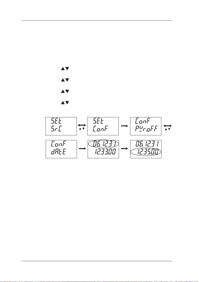
7.3 Conguration
(3) Date/Time
You can set the date and time.
(These settings are set to Japan time at the time of shipment.)
Top row: Year (2 digits)/Month/Day
Bottom row: Hour/Minute/Second
1
2
3
4
5
6
7
8
Simultaneously press the CLEAR and ENTER keys to switch to
setting mode.
Use the keys to select Conguration.
Press the ENTER key to conrm the selection.
Use the keys to select the date/time setting.
Press the ENTER key to conrm the selection.
Use the keys to set year/month/day on the top row. (Flashes)
Press the ENTER key to conrm the setting.
Use the keys to set hour/minute/second on the bottom row.
(Flashes)
ENTER
ENTERENTER
7-6
To return to normal mode from setting mode, simultaneously
press the CLEAR and ENTER keys.
(Press the CLEAR key to go back one level.)
(4) Temperature Scale Standard
You can select from ITS-90 and IPTS-68 for the temperature scale standard.
(default setting: ITS-90)
ITS-90: 1990 International Temperature Scale
IPTS-68: 1968 International Practical Temperature Scale
For details, refer to "4.6 Source Resistance Temperature Detector (RTD)
Signals."
IM CA150E
Page 93

1
2
3
4
5
6
7
8
8. Communication Function
You can congure the instrument and conrm setting values and
measurement values from a personal computer.
NOTE
You can use a communication cable to connect the instrument to an RS232
compliant serial port of a personal computer, etc.
In printer mode, you can output source values and measurement values at
preset intervals.
Communication Function
8.1 CableConnectionandInterfaceSpecications
Cable Connection
Recommended communication cable
RS232 (D-SUB 9-pin) cross cable
Connect the communication cable to the RS232 connector on
the side of the instrument.
RS232 Settings
Baud rate: 9600 bps
Parity: None
Stop bit: 1 bits
Data length: 8 bits
Flow control: None (Xon/Xoff control for printing only)
Terminator: Fixed to CrLf
IM CA150E
8-1
Page 94

8.2 Communication Command List
8.2 Communication Command List
Command Description
AS Sets and queries the source/SINK of the current (DCA)
BL Queries whether the back light is on or off
BT Starts charging the batteries when the AC adapter is
connected
CD Sets the source value during calibration
CL Sets and queries the calibration item
CMF Sets and queries the calibration measurement function
CP Sets the calibration point
CS Sets the measurement value during calibration
CSF Sets and queries the calibration source function
CW Writes the calibration data
DT Sets and queries the date and time
DW Decreases the m (th) digit of the source value by 1 digit
ESC C/RC Initializes the setting information (setting conditions)
ESC S Outputs the status byte
H Sets and queries the output header of the OD and OM
commands
HD Holds and queries the measurement value indication
IM Sets and queries the mask of status byte
MF Sets and queries the measurement function
MO Turns on (starts)/turns off (stops) and
queries the measurement value indication
MR Sets and queries the measurement range
ND Sets and queries the n and m values for divided output
(n/m)
NM Sets and queries divided output (n/m)
When
Normal
O X
O X
O X
X O
X O
X O
X O
X O
X O
X O
X O
O O
O X
O O
O O
O X
O O
O X
O X
O O
O X
O X
When
Setting
8-2
IM CA150E
Page 95

1
2
3
4
5
6
7
8
8.2 Communication Command List
ommand
C
OB Queries the battery charge state
OD Outputs the measurement values
OE Outputs the error information
OM Requests sending of memory data
OR Queries whether an external RJ sensor is connected
OS Outputs the setting information (conditions)
PU Sets and queries display of PULSE (source)
SD Sets and queries the source values
SF Sets and queries the source function
SO Starts/stops and queries source
SR Sets and queries the source range
SY Switches and queries normal mode and calibration mode
TE Sets and queries TC and RTD (source) display
TT Sets and queries the international temperature standard
UP Increases the m (th) digit of the source value by 1 digit
VO Sets and queries start/stop of 24 VDC (LOOP)
Description
power supply
When
Normal
O X
O O
O O
O X
O X
O X
O X
O X
O X
O O
O O
O O
O X
X O
O O
O X
When
Setting
Communication Function
IM CA150E
8-3
Page 96

8.3 Detailed Description of Commands
8.3 Detailed Description of Commands
Setting and Control
Command: Send command syntax
Answer: Return data syntax of command (setting, control) with
no response.
When an error occurs, the same data as that of
the error message ERRm (m = error number) displayed on
the LCD is returned.
Query
Command: Send command syntax
Return: Return data syntax of command (query) with response.
Operating Condition by Mode
Normal: The command can be used during normal measurement/
source operation.
Setting: The command can be used in setting mode (Chapter 7) or
calibration mode (Chapter 9).
8-4
For details on whether each command can be used in other modes,
refer to "8.5 Table of Valid Communication Commands."
IM CA150E
Page 97

1
2
3
4
5
6
7
8
8.3 Detailed Description of Commands
AS Normal SettingSets and queries the source/SINK of the current (DCA)
Command = ASm<Delimiter> → Answer = ASm <Delimiter>
Command = AS?<Delimiter>
Parameter m=0: Source (Generation)/1:SINK (Draw in)
When the current source setting value is 0 mA and the measurement
function is other than DCA, an error is returned.
BL Normal SettingQueries whether the back light is on or off
Command = BLm<Delimiter> → Answer = BLm <Delimiter>
Command = BL?<Delimiter>
Parameter m=0: Off/1: On
default value of m = 0 (Off)
→ Return = ASm <Delimiter>
→ Return = BLm <Delimiter>
○ ×
Communication Function
○ ×
BT Normal SettingStarts charging the batteries when the AC adapter is connected
Command = BT<Delimiter>
An error is generated in the following cases (LCD indication)
• AC power supply is not connected (Err 14)
• Charging has already started (Err 12)
Use the OB command to confirm the charge state.
○ ×
Note:
At the beginning of using communication function send "ESC C" or "RC"
command in order to initialize the unit.
IM CA150E
8-5
Page 98

8.3 Detailed Description of Commands
CD Normal SettingSets the source value during calibration
Command = CD<Delimiter>
During generation in calibration mode, sets the current output source
values as the calibration values for the selected function, range, and
scale (+FS/0).
CL Normal SettingSets and queries the calibration item
Command = CLm<Delimiter>
Command = CL?<Delimiter>
Parameter m=3: (Calibration) Source/4: (Calibration) Measure
CMF Normal SettingSets and queries the calibration measurement function
Command = CMFm<Delimiter>
Command = CMF?<Delimiter>
Parameter
m=0: DCV/1: DCA/2: Ω
default Value of m=0 (DCV)
CP Normal SettingSets the calibration point
Command = CPm<Delimiter>
Parameter
m=0: + FS Calibration/1: + Zero Calibration/2: -FS Calibration
→ Answer = CD <Delimiter>
→ Answer = CLm <Delimiter>
→ Return = CLm <Delimiter>
→ Answer = CMFm <Delimiter>
→ Return = CMFm <Delimiter>
→ Answer = CPm <Delimiter>
× ○*
× ○*
× ○*
× ○*
CS Normal SettingSets the measurement value during calibration
Command = CS<Delimiter>
During measurement in calibration mode, sets the current input
measurement values as the calibration values for the selected function,
range, and scale (+FS/0/-FS ).
CSF Normal SettingSets and queries the calibration source function
Command = CSFm<Delimiter>
Command = CSF?<Delimiter>
Parameter m=0: DCV/1: DCA/2: Ω
default Value of m=0 (DCV)
CW Normal SettingWrites the calibration data
Command = CW<Delimiter>
Answer = CW, OK<Delimiter> (Normal End)
Writes to EEPROM after calibrating each function and range.
If the power is turned off without executing this command, the values that
were calibrated just before are discarded.
→ Answer = CS <Delimiter>
→ Answer = CSFm <Delimiter>
→ Return = CSFm <Delimiter>
→
*: Can only be used in calibration mode of setting mode.
8-6
× ○*
× ○*
× ○*
IM CA150E
Page 99

1
2
3
4
5
6
7
8
8.3 Detailed Description of Commands
DT Normal SettingSets and queries the date and time
Command = DTyyyymmddhhmmss<Delimiter> →
Answer = DTyyyymmddhhmmss<Delimiter>
Command = DT? (CrLf)
Return = yyyyy/mm/dd, hh:mm:ss<Delimiter>
Parameter (default Value)
yyyy: Year (2006) 4 byte, mm: Month (04) 2 byte, dd: Day (01) 2 byte
hh: Hour (00) 2 byte, mm: Minute (00) 2 byte, ss: Second (00) 2 byte
Setting (confirmation) of the 2 leftmost digits of the year is only possible
for the communication function.
(Using the operation keys to change the values of the 2 leftmost digits on
the LCD will not move up or down to the 2 rightmost digits.)
DW Normal SettingDecreases the m (th) digit of the source value by 1 digit
Command = DWm<Delimiter> → Answer = DW, OK<Delimiter>
Parameter m = 1 to 5 (1: Least Significant Digit to 5: Most Significant
Digit)
ESC C
or
RC
("ESC" = ASCII 0 × 1B)
Command = ESC C<Delimiter>
or
Command = RC <Delimiter>
The following settings (common setting item) are not initialized.
• Auto power off setting
• Communication setting
• International temperature standard selection (ITS-90/IPTS-68)
• Time setting
→
× ○
Communication Function
○ ○
Normal SettingInitializes the setting information (setting conditions)
○ ×
ESC S Normal SettingOutputs the status byte
H Normal SettingSets and queries the output header of the OD and OM commands
HD Normal SettingHolds and queries the measurement value indication
("ESC" = ASCII 0 × 1B)
Command = ESC S<Delimiter>
The status byte is output. (Decimal number)
(Refer to "8.6 Status Byte Format.")
Command = Hm<Delimiter> → Answer = Hm <Delimiter>
Command = H?<Delimiter>
Parameter m=0: No/1: Yes
default Value of m=0 (No)
Command = HDm<Delimiter> → Answer = HDm <Delimiter>
Command = HD?<Delimiter>
Parameter m=0: Indication Update/1: Indication Hold
→ Return = Hm <Delimiter>
→ Return = HDm <Delimiter>
○ ○
○ ○
○ ×
IM CA150E
8-7
Page 100

8.3 Detailed Description of Commands
IM Normal SettingSets and queries the mask of status byte
Command = IMm<Delimiter> → Answer = IMm <Delimiter>
Command = IM?<Delimiter>
Performs detection or sets mask for each bit of status byte.
If IM0 is set, all information bits are masked.
If IM63 is set, the current operating conditions are reflected for all
information bits.
(No mask)
Parameter m = 0 to 63 (Decimal number)
1: Detects bit 0 (Measurement Ends)
2: Detects bit 1 (Output Change Ends)
4: Detects bit 2 (Syntax Error)
8: Detects bit 3 (Overrange)
16: Detects bit 4 (24 V Loop Output Error)
32: Detects bit 5 (Error During Output)
(Bits 6 and 7 of the status byte are fixed bits.)
default Value of m = 63 (No Mask)
MF Normal SettingSets and queries the measurement function
Command = MFm<Delimiter> → Answer = MFm <Delimiter>
Command = MF?<Delimiter>
Parameter
m=0: DCV/1: DCA/2: Ω/3: TC/4: RTD/5: Freq
MO Normal SettingTurns on (starts)/turns off (stops) and queries the measurement value
indication
Command = MOm<Delimiter> → Answer = MOm <Delimiter>
Command = MO?<Delimiter>
Parameter m=0: Turn off (stop)/1: turn on (start)
MR Normal SettingSets and queries the measurement range
Command = MRm<Delimiter> → Answer = MRm <Delimiter>
Command = MR?<Delimiter>
→ Return = IMm <Delimiter>
○ ○
○ ×
→ Return = MFm <Delimiter>
○ ×
→ Return = MOm <Delimiter>
○ ○
→ Return = MRm <Delimiter>
8-8
Parameter
[DCV] m = 0: 500 mV/1: 5 V/2: 35 V
[DCA] m = 0: 20 mA DC/1: 100 mA DC
[Ω] m = 0: 500 Ω/1: 5 kΩ/2: 50 kΩ
[TC] m = 0: K/1: E/2: J/3: T/4: R/5: B/6: S/7: N/8: L/9: U
[RTD] m = 0: PT100/1: JPT100
[Freq] m = 0: 100 Hz/1: 1000 Hz/2: 10 kHz/3: CPM/4: CPH
ND Normal SettingSets and queries the n and m values for divided output (n/m)
Command = NDnm<Delimiter> → Answer = NDnm <Delimiter>
Command = ND?<Delimiter>
Parameter
n = n value (2 digits from 00 to 19, n ≤ m)
m = m value (2 digits from 01 to 19, n ≤ m)
default Value of n = 01 and m = 01
→ Return = NDnm <Delimiter>
○ ×
IM CA150E
 Loading...