

Specifications
The latest product information is available at our web site http://www.yokogawa.com/tm/. Review the specifications to determine which model is right for you.
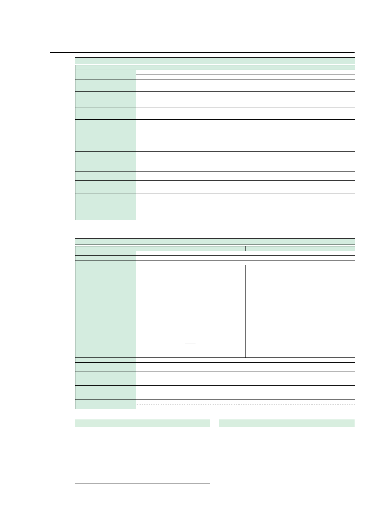
Input Specifications
Input type
Rated values (ranges)
Measuring instrument loss
(input resistance)
Maximum instantaneous allowed input
(1 cycle, 20 ms duration)
Maximum instantaneous allowed input
(1 second duration)
Maximum continuous allowed input
Maximum continuous common mode voltage
(with 50/60 Hz input)
CMRR
600 Vrms across input terminal and case
Input terminal type
A/D converter Simultaneous conversion of voltage and current inputs
Range switching Ranges can be set manually, automatically, or through online controls.
Measurement mode switching Any of the following, selected manually or through online controls: RMS (true rms value measurements for both voltage and current), V MEAN (calibration of
Note: Current direct input and external sensor input cannot both be used at the same time. When you operate current input terminals and external input terminals, please be careful.
Since these terminals are electrically connected inside the instrument.
1, Connect wires that match the size of the measurement current.
2, Factory setting
Parameter Voltage
Resistance voltage divider
15/30/60/150/300/600 V
Input resistance: Approximately 2 MΩ
Input capacitance: Approximately 13 pF
Peak voltage of 2.8 kV or rms value of 2.0 kV (whichever is less)
Peak voltage of 2.0 kV or rms value of 1.5 kV (whichever is less)
Peak voltage of 1.5 kV or rms value of 1.0 kV (whichever is less)
600 Vrms (with output connector protective cover),
50/60 Hz, -80 dB or higher (±0.01% of range or less) with voltage input terminals shorted and current input terminals open and external input terminals shorted
Reference value (up to 100 kHz): ±((Maximum range rating)/(Range rating) × 0.001 × f% of rng) or less (voltage range and 0.5-20 A current range and external
3
)
input range
±((Maximum range rating)/(Range rating) × 0.0002 × f% of rng) or less (WT210; 5-200 mA range)
Note: 0.01% or higher. f is in kHz. 3 Decuple the above-formula about the external input range.
Plug-in terminal (safety terminal) Direct input: Large binding post
Resolution: 16 bits
Maximum conversion speed: Approximately 20 µs (approximately 51 kHz)
Auto-range function
Range raising: When a measurement exceeds 130% of the rating, or when the peak value exceeds approximately 300% of the rating
Range lowering: When a measurement falls to 30% or less of the rating, and the peak value falls to approximately 300% or less of the rating for the low range
average-value-rectified rms value for voltage; true rms value measurement for current), DC (simple averages for both voltage and current)
CAT II / 400 Vrms (without output connector protective cover) CAT II
Floating input
Shunt input system
Direct input: 5/10/20/50/100/200 mA (WT210 only)
Direct input: Approximately 500 mΩ + approximately 0.1 µH (5-200 mA; WT210)
External input:
0.5-20 A (WT210/WT230): Peak current of 450 A or rms value of 300 A (whichever is less)
5-200 mA (WT210): Peak current of 150 A or rms value of 100 A (whichever is less)
External input: Peak value of 10 times range or less
0.5-20 A (WT210/WT230): Peak current of 150 A or rms value of 40 A (whichever is less)
5-200 mA (WT210): Peak current of 30 A or rms value of 20 A (whichever is less)
External input: Peak value of 10 times range or less
0.5-20 A (WT210/WT230): Peak current of 100 A or rms value of 30 A (whichever is less)
5-200 mA (WT210): Peak current of 30 A or rms value of 20 A (whichever is less)
External input: Peak value of 5 times range or less
External input: BNC connector (insulation type)
; 0.5/1/2/5/10/20 A (WT210/WT230)
External input (optional): 2.5/5/10 V or 50/100/200 mV
Approximately 6 mΩ + 10 mΩ (max)2 + approximately 0.1 µH (0.5-20 A; WT210)
Approximately 6 mΩ approximately 0.1 µH (0.5-20 A; WT230)
Approximately 100 kΩ (2.5/5/10 V), approximately 20 kΩ (50/100/200 mV)
Measurement Functions
System
Frequency range
Crest factor
Accuracy (three months after calibration)
Note: In the accuracy calculation formula, f is in kHz.
Power factor effect
Note: In the accuracy calculation formula, f is in kHz.
Effective input range
Accuracy (12 months after calibration)
Line filter function
Accuracy with line filter on
Temperature coefficient
Display updating intervals
Lead/lag detecting
Measurement lower limit frequency
Parameter Voltage/current
(Conditions)
Temperature: 23±5°C
Humidity: 30-75% RH
Input waveform: Sinewave
Power factor: cosϕ = 1
In-phase voltage: 0 V DC
Frequency filter: ON at 200 Hz or less
Scaling: OFF
Display digits: 5 digits
After CAL is executed
DC:
0.5 Hz ≤ f < 45 Hz:
45 Hz ≤ f ≤ 66 Hz:
66 Hz < f ≤ 1 kHz:
1 kHz < f ≤ 10 kHz:
10 kHz < f ≤ 100 kHz:
* Add ±10 µA to the current DC accuracy.
1-130% of voltage/current range rating (for accuracy at 110-130%, add the reading tolerance × 0.5 to the above accuracy)
Add the accuracy's reading tolerance (three months after calibration) × 0.5 to the accuracy three months after calibration.
A low-pass filter can be inserted in the input circuit for measurement. The cutoff frequency (fc) is 500 Hz.
Voltage and current: Add 0.2% of rdg at 45-66 Hz. Add 0.5% of rdg below 45 Hz.
Power: Add 0.3% of rdg at 45-66 Hz. Add 1% of rdg below 45 Hz.
±0.03% of range/°C at 5-18°C and 28-40°C.
0.1/0.25/0.5/1/2/5 seconds
Lead/lag is detected correctly when phase difference equal to or greater than ±5° with both voltage and current inputs as sine waves equal to or greater than
50% of rated range-value, and the frequency is between 20 Hz to 2 kHz.
Data updating rate 0.1 second 0.25 second 0.5 second 1 second 2 seconds 5 seconds
Measurement lower limit frequency
±(0.2% or rdg + 0.2% of rng)*
±(0.1% of rdg + 0.2% of rng)
±(0.1% of rdg + 0.1% of rng)
±(0.1% of rdg + 0.2% of rng)
±((0.07 × f)% of rdg + 0.3% of rng)
±((0.5% of rdg + 0.5% of rng)
±((0.04 × (f-10))% of rdg)
25 Hz 10 Hz 5 Hz 2.5 Hz 1.5 Hz 0.5 Hz
Digital sampling; sum of averages method
3 (with rated input) 300 (with minimum effective input)
DC, and 0.5 Hz to 100 kHz
DC:
0.5 Hz ≤ f < 45 Hz:
45 Hz ≤ f ≤ 66 Hz:
66 Hz < f ≤ 1 kHz:
1 kHz < f ≤ 10 kHz:
10 kHz < f ≤ 100 kHz:
* Add ±10 µA
For cosϕ = 0
45 Hz ≤ f ≤ 66 Hz: ±0.2% of VA (VA is a reading value of apparent power)
Reference data (up to 100 kHz): ±((0.2 + 0.2 × f)% of VA)
Indicated value tolerance for 0 < cosϕ < 1
Add (tanϕ × (effect when cosϕ = 0)% of power reading to the above power accuracy.
Note: ϕ is the phase angle between voltage and current.
×
Current
1
Active power
±(0.3% or rdg + 0.2% of rng)*
±(0.3% of rdg + 0.2% of rng)
±(0.1% of rdg + 0.1% of rng)
±(0.2% of rdg + 0.2% of rng)
±(0.1% of rdg + 0.3% of rng)
±((0.067 × (f-1))% of rdg)
±(0.5% of rdg + 0.5% of rng)
±((0.09 × (f-10))% of rdg)
voltage reading to the power DC accuracy.
rng: Range rdg: Reading
Frequency Measurements
Measurement inputs
Measurement system
Measurement frequency ranges
Accuracy: ±(0.06% of rdg)
Conditions: Input equal to at least 30% of voltage/current rated range.
: V1, V2, V3, A1, A2, or A3 (select one)
: Reciprocal system
100 ms: 25 Hz ≤ f ≤ 100 kHz
250 ms: 10 Hz ≤ f ≤ 100 kHz
500 ms: 5 Hz ≤ f ≤ 100 kHz
1 sec: 2.5 Hz ≤ f ≤ 100 kHz
2.5 sec: 1.5 Hz ≤ f ≤ 50 kHz
5 sec: 0.5 Hz ≤ f ≤ 20 kHz
Frequency filter function ON at 200 Hz and below.
Frequency filter cutoff frequency: 500 Hz
Communication Functions (Optional for the WT210)
GP-IB or serial interface (RS-232-C) (select one)
GP-IB
Electrical and mechanical specifications:
Functional specifications:
Protocol: Conforms to IEEE Standard 488.2-1992.
Code used: ISO (ASCII) code
Addresses: 0-30 talker/listener addresses can be set.
Serial interface (RS-232-C)
Transmission mode
Baud rates: 1200, 2400, 4800, 9600 bps
Conform to IEEE Standard 488-1978 (JIS C1901-1987).
SH1, AH1, T5, L4, SR1, RL1, PR0, DC1, DT1, C0
: Asynchronous
Specifications
Calculation Functions Internal Memory Functions
Single-
Three-phase 3-wire
phase 3-
(2 voltages,
wire
Voltage ∑V (V1 + V3)/2
Current ∑A
Active power ∑W
Reactive
power
var, ∑var
Apparent
power
VA, ∑VA
Power
factor PF,
∑PF
Phase
angle deg,
∑deg
Notes
1. This equipment's apparent power (VA), reactive power (var), power factor (PF),
and phase angle (deg) are calculated from voltage, current, and active power.
(Therefore, if the input contains a distorted wave, the values may not match those
of other measuring instruments based on different measurement principles.)
2.
If either voltage or current falls to 0.5% of the range rating or less, then the apparent
power (VA) and reactive power (var) are displayed as zero, and errors are displayed
for power factor (PF) and phase angle (deg).
3. The sign of the var of each phase is displayed with +(positive). In the ∑var
calculation, the var value for each phase is calculated with a negative sign if the
current input leads the voltage input, and with a positive sign if the current input
lags the voltage input. Then the value of ∑ var may be displayed with –(negative).
4. Apparent power (VA) and reactive power (var) cannot be calculated and displayed
at the harmonics measurement mode.
vari = (VA2 - W2)
VAi = Vi × Ai
Pfi = Wi/VAi ∑W/∑VA
degi =
-1
cos
(Wi/VAi)
(A1 + A3)/2
W1 + W3
var1 + var3
VA1 + VA3
-1
cos
(∑W/∑VA)
2 currents)
2
3
(VA1 + VA3)
Three-phase 3-wire
(3 voltages,
3 currents)
(V1 + V2 + V3)/3
(A1 + A2 + A3)/3
3
(VA1 + VA2 + VA3)
3
Threephase 4wire
W1 + W2 + W3
var1 + var2 + var3
VA1 + VA2 + VA3
Display Functions
Display unit: 7-segment LED (light-emitting diode)
Display areas: 3
Display area
A
V, A, W, VA, var (for each element), integration elapsed time
B
V, A, W, PF, deg (for each element, percentage (content percentage, THD)
C
V, A, W, V/AHz, Vpk, Apk, ±Wh, ±Ah (for each element), MATH
Measurement parameters
V, A, W, VA, var
PF
deg
±Wh, ±Ah
VHz, AHz
Display digits: 4 or 5 digits (selectable by user).
Factory default setting is 5 digits.
Units: m, k, M, V, A, W, VA, var, Hz, h±, deg, %
Display updating intervals: 0.1/0.25/0.5/1/2/5 seconds
Response time: Maximum 2 times the display updating interval (time required
Maximum display: 140% of voltage/current range rating
Minimum display: About Vrms, Arms, and Ah, 0.5% of range rating.
Display scaling function
Effective digits: Selected automatically according to the digits in the voltage and
Setting range: 0.001 to 9999
Averaging function
There are two averaging methods (selectable by user):
Exponential average
Moving average
Auto-range monitor
An LED turns on when the input value is outside the range set for the auto-range.
MAX hold function
This function can be used to hold V, A, W, VA, var, Vpk, and Apk at maximum values.
MATH functions
System: When a function key on DISPLAY C is pressed to select the
Maximum display
99999
±1.0000
±180.0
999999
99999
for display value to enter accuracy range of final value with line
filter off, when range rating abruptly changes from 0% to 100%,
and from 100% to 0%)
Less than 0.5% is zero suppression.
current ranges.
In cases where response can be set and exponential average is used, the attenuation
constant can be selected. In cases where a moving average is used, the number of
averages N can be selected from 8, 16, 32, and 64.
MATH functions, it is possible to perform efficiency (WT230 only)
and input crest factor measurements, as well as arithmetic
calculations on DISPLAY A and B measurements. In addition, it
is possible to display average active power for time-converted
integrated power.
Displayed information
Display resolution
0.001%
0.01%
0.1*
0.0001%
Input frequency/20,000
Measurement data
Stored data
WT210 (760401)
WT230 (760502)
WT230 (760503)
Store interval: Display updating interval and 1 second to 99 hours, 59 minutes,
Recall interval: Display updating interval and 1 second to 99 hours, 59 minutes,
Panel setting information
Normal measurement
Data for 600 samples
Data for 300 samples
Data for 200 samples
and 59 seconds
and 59 seconds
(Both can be set in 1-second increments.)
: Four different patterns of panel setting information can be written/
read.
Harmonic Measurement Function (optional)
System: PLL synchronization
Measurement frequency range:
Maximum display: 99999
Display digits: 4 or 5 digits (selectable by user).
Measurement parameters: V, A, W, deg (WT210), V1, V2, V3, A1, A2, A3, W1, W2,
Measurement element: These parameters can only be measured simultaneously for
Sampling speed, window width, and analysis orders
The values for these parameters vary according to the input fundamental frequency
as shown below.
Fundamental frequency Sampling speed Window width Analysis orders
40 ≤ f < 70 Hz f × 512 Hz 2 periods of f 50
70 ≤ f < 130 Hz f × 256 Hz 4 periods of f 50
130 ≤ f < 250 Hz f × 128 Hz 8 periods of f 50
250 ≤ f ≤ 440 Hz f × 64 Hz 16 periods of f 30
FFT data length: 1024
FFT processed word length: 32 bits
Window function: Rectangular
Display updating interval:
Accuracy: Add ±0.2% of range to normal measurement accuracy.
Fundamental frequency in range of 40-440 Hz
Factory default setting is 5 digits.
W3, deg1, deg2, deg3 (WT230), individual harmonic levels, rms
voltage, rms current, active power, fundamental frequency PF,
harmonic distortion rate, individual harmonic content
a single specified input element.
0.25/0.5/1/2/5 seconds Updating is slower during online output
according to the communication speed and the number of
parameters transferred.
Note: For nth-order component input, add ((nth order reading)
× (10/(m+1))%) to the n+mth order and n-mth order.
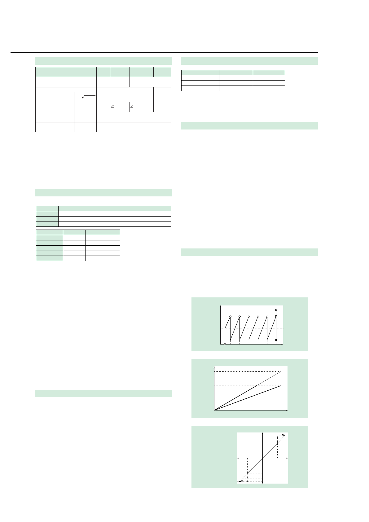
D/A Output (optional)
Output voltage: ±5 V FS (maximum approximately ±7.5 V) for each rated value
Number of outputs: 12 parameters with /DA12 option; 4 parameters with /DA4 option
Output data selection
Accuracy: ±(equipment accuracy + 0.2% of FS)
D/A converter: 12-bit resolution
Response time: Maximum 2 times the display updating interval
Updating interval: Same as the equipment's display updating interval
Temperature coefficient: ±0.05%˚C of FS
Output type
Frequency
Integration
: Can be set separately for each channel.
D/A output
7.5V
5.0V
2.5V
0.5V
0
0.5Hz 100Hz10Hz1Hz 1kHz 10kHz
D/A output
7.0V
5.0V
For input equal to 140% of rating
Integration Functions
Display resolution: The minimum display resolution changes together with the
Maximum display: -99999 to 999999 MWh/MAh
Modes: Standard integration mode (timer mode), continuous integration
Timer: Automatic integration start/stop based on timer setting.
Count over flow: When the integrated value exceeds 999999 MWh/MAh or falls
Accuracy: ±(display accuracy + 0.1% of rdg)
Timer accuracy: ±0.02%
Remote control: Starting, stopping, and resetting can be controlled through
integrated value.
mode (repeat mode), manual integration mode
Setting range: 000 h:00 min:00 sec to 10000 h:00 min:00 sec
(If the time is set to zero, manual mode is automatically set.)
to at least -99999 MWh/MAh, the elapsed time is saved and the
operation is stopped.
external contact signals. This function is only available when
option /DA4, /DA12 or /CMP is installed.
Other parameters
Display
140%
100%
-100%
-140%
Note: For PF and
deg, there is no
output between ±5
and ±7 V. When an
error occurs,
approximately 7.5 V
are output.
0
t0:
0%
Rated setting time
Output
7.0V
5.0V
0V
-5.0V
-7.0V
Harmonic measurement
Data for 30 samples
Data for 30 samples
Data for 30 samples
For rated input
D/A output
7.5V
7.0V
5.0V
-100%-140%
0V
-5.0V
-7.0V
-7.5V
100kHz
Display value
t0
Integration time
Display value
140%100%

External Input (Optional)
Model or part number
751533-E2
751533-J2
751534-E2
751534-J2
751533-E3
751533-J3
751534-E3
751534-J3
Specification
For WT210 EIA standalone installation
For WT210 JIS standalone installation
For WT210 EIA connected installation
For WT210 JIS connected installation
For WT230 EIA standalone installation
For WT230 JIS standalone installation
For WT230 EIA connected installation
For WT230 JIS connected installation
Order quantity
1
1
1
1
1
1
1
1
Product
Rack mounting kit
Rack mounting kit
Rack mounting kit
Rack mounting kit
Rack mounting kit
Rack mounting kit
Rack mounting kit
Rack mounting kit
Ask Yokogawa for information on rack mounts in which WT210 and WT230 are combined.
B9317WD
B9284LK
1.5 mm hex wrench
External sensor cable
For fastening cable on 758931
For external input; 50 cm
Model number
Description
Single-phase 2-wire
Single-phase 3-wire
Three-phase 3-wire (2 voltages, 2 currents)
Three-phase 3-wire (3 voltages, 3 currents)
Three-phase 4-wire
760401
✓
–
–
–
–
760502
✓
✓
✓
–
–
760503
✓
✓
✓
✓
✓
Wiring
Model
Select either /EX1 or /EX2 for the voltage output-type current sensor.
/EX1: 2.5/5/10 V
/EX2: 50/100/200 mV
Specifications: See the section on input specifications.
Comparator Output (Optional)
Output method: Normal-open and normal-close relay contact output (pair)
Number of output parameters and settings:
Contact capacitance:24 V/0.5 A
D/A output (4-channel)
Four parameters; can be set separately on each output channel.
:See section on D/A output (optional)
External Control Signal (with D/A or /CMP Option Only)
External control signals
Input: TTL level negative pulse
:EXT-HOLD, EXT-TRIG, EXT-START, EXT-STOP, EXT-RESET,
INTEG-BUSY
General Specifications
Warmup time: Approximately 30 minutes
Operating temperature and humidity ranges: 5-40˚C, 20-80% RH (no condensation)
Storage temperature
Maximum operating elevation: 2000 meters
Insulating resistance
Insulating withstand voltage:
Power supply: Free power supply (100-240 V), 50/60 Hz frequency
Consumed power: Max 35 VA for WT210, max 55 VA for WT230
External dimensions for WT210:
External dimensions for WT230:
Weight: Approximately 3 kg for WT210, approximately 5 kg for WT230
Safety standard Complying standard EN61010-1
Emission Complying standard EN61326 Class A
Immunity Complying standard EN61326 Annex A
: -25-60˚C (no condensation)
: 50 MΩ or higher at 500 V DC across all of the following areas:
Voltage input terminals (ganged) and case
Current input terminals (ganged) and case
Voltage input terminals (ganged) and current input terminals
(ganged)
Voltage input terminals (ganged) of each element
Current input terminals (ganged) of each element
Voltage input terminals (ganged) and power plug
Current input terminals (ganged) and power plug
Case and power plug
3700 V for one minute at 50/60 Hz across all of the following
areas:
Voltage input terminals (ganged) and case
Current input terminals (ganged) and case
Voltage input terminals (ganged) and current input terminals
(ganged)
Voltage input terminals (ganged) of each element
Current input terminals (ganged) of each element
Voltage input terminals (ganged) and power plug
Current input terminals (ganged) and power plug
1500 V for one minute at 50/60 Hz across case and power plug
Approximately 213 × 88 × 379 mm (WHD) (excluding projections)
Approximately 213 × 132 × 379 mm (WHD) (excluding
projections)
Overvoltage category (Installation category) II
Pollution degree 2
EN61000-3-2
EN61000-3-3
AS/NZS 2064 Class A
■ Exterior View
Unit : mm
250 73 23
213
356
359
■ Model Numbers and Suffix Codes
-D
-F
-R
-Q
-C1
-C2
Suffix code
/C1
/C2
/EX1
/EX2
/HRM
Suffix code
-D
-F
-R
-Q
/EX1
/EX2
/HRM
WT210 single-input element model
UL/CSA standard
VDE
standard
AS
standard
BS
standard
GP-IB communication interface
Serial (RS-232-C) communication interface
External input 2.5/5/10 V
External input 50/100/200 mV
Harmonic measurement function
/DA4
4-channel DA output
/CMP
Comparator and D/A, 4 channels each
WT230 2-input element model
WT230 3-input element model
GP-IB communication interface
Serial (RS-232-C) communication interface
UL/CSA standard
VDE
standard
AS
standard
BS
standard
External input 2.5/5/10 V
External input 50/100/200 mV
Harmonic measurement function
/DA12
12-channel DA output
/CMP
Comparator and D/A, 4 channels each
Description
Description
Select one
Select one
Select one
Select one
Select one
Select one
Model number
760401
Power cord
Options
Note: The WT210 communication interface cannot be changed or modified after delivery.
Model number
760502
760503
Interface
Power cord
Options
■ Standard Accessories
Power cord, Power fuse, Current input protective cover, Rubber feet for the hind feet,
24-pin connector (provided only on options/DA4, /DA12, and /CMP), User’s manual
■ Wiring Types and Model Numbers
■ Rack mounts
179
13
213 327
8819
13221
WT210
23
28.5
34
WT230
■ Accessories (sold separately)
 Loading...