

Page 1

Instruction
Manual
540 51
TM10 Thermo-Collector
IM 54051-E
1st Edition
Page 2

This instruction manual describes how to operate the TM10 Thermo-Collector.
■ Intended Readers
This manual is primarily intended for two groups of readers: “operators” who actually measure temperatures with this TM10 Thermo-Collector and, “engineers” who are qualified to
perform setup and data processing operations for this instrument.
■ Structure of the manual
This manual is organized into the following four parts:
● Information Required before Use
This part explains basic information, including the names and functions of each component
of this instrument and how to input characters, etc. Read this part before using this instrument.
● Preparation for Measurement
This part explains “Thermo-Collector” software and how to perform setup. This part must be
read before starting preparation for temperature measurement.
● Temperature Measurement
This part explains the major operations required to actually measure temperatures. Read this
part before commencing temperature measurement.
● Utilizing the Measurement Data
This part explains the procedures for outputting the data measured with this instrument to a
personal computer or printer. Read this part to use or analyze the data measured with this
instrument.
■ Checking contents of the package
Perform a visual check on the TM10 Thermo-Collector to make sure it is not damaged.
In addition, make sure that the following items have been supplied. If any of the items are
missing, please contact the dealer where this product was purchased.
Keep this box in case this product needs to be returned to Yokogawa M&C Corporation.
Item name Quantity
TM10 Thermo-Collector 1
“Thermo-Collector” software installer FD 2
LR6 alkaline dry cell 2
Dust-proof seal (for sealing screw holes on the back of the main unit) 2
Instruction Manual (this document) 1
IM 54051-E
ii
Page 3
■ Precautions required for safe use
● About this manual
• Read this manual to gain a thorough understanding of this instrument before operating it.
• This manual only describes the functions of this product and is not intended to guarantee
the applicability of this product to user’s particular purpose.
• This manual shall not be reproduced or copied in part or in whole without permission from
Yokogawa M&C Corporation.
• The contents of this manual may be subject to change without notice.
• Should the user find any errors, or unclear or missing sections in this document, contact the
dealer where this product was purchased, or the marketing division of Yokogawa M&C
Corporation.
● Disassembly or retrofit
Do not disassemble or retrofit this instrument. Only qualified Yokogawa M&C Corporation
service personnel are authorized to disassemble and service the main unit.
● Precautions on handling
• Only parts and consumables specified by Yokogawa M&C Corporation should be used in
this product.
• Do not store this instrument in a location where it will be subject to direct sunlight or high
temperatures, otherwise it may be discolored or deformed.
● Notes on protection and safety of this product
• Follow the safety instructions of this manual when handling the main unit or accessories to
be connected to the main unit. If the main unit or accessories are not handled as specified
in this manual, Yokogawa M&C Corporation cannot guarantee the safety of this product.
• The “
that must be observed when handling this instrument. Refer to this manual for information
about how to operate this instrument.
• Throughout this manual the following safety conventions are used.
Warning” mark that appears on the back of the main unit indicates the precautions
Warning
Used if the operator is at risk of being severely injured or killed.
Caution
Used if the operator is at risk of being injured or if the instrument may be damaged.
Note
Used to draw attention to important information about handling the instrument or useful information about the operations and functions of this instrument.
iiii
IM 54051-E
Page 4
[TIP]
Contains information supplementary to the main text.
See Also
Provides a reference to related topics in this document.
■ Precautions for handling components
Always observe the following precautions to avoid operator injury and damage to the equipment.
● Probe
Warning
Do not point the tip of a needle-type standard probe or needle-type high-speed probe
at another person. The tip of the needle is very sharp and can cause injury.
Caution
• Do not touch the stylus (metal) of a probe which has just measured a hot object. A
hot stylus can cause a burn.
• Do not use a worn or damaged probe. Such probes cannot measure temperatures
correctly.
• Before removing the probe from the main unit, pull the probe away from the object
to be measured.
• If a needle-type standard probe or needle-type high-speed probe is used, stick it
into a measuring object half the dimension of the probe’ s stylus (metal). If it is stuc k
in too deeply , the operator ma y be burnt due to heat transf er to the probe grip. Also,
the probe itself may be damaged.
• The probe grip and the cable connected to the main unit must be maintained at a
temperature between -20C and 50C. They have a small heat resistance, unlike the
stylus (metal) of the probe.
● Battery
Caution
If this instrument will not be used for a long period, remove the battery from the main
unit. Otherwise, the battery liquid may leak and damage the main unit or cause it to
malfunction.
IM 54051-E
iiiiii
Page 5

■ Exemptions
•Yokogawa M&C Corporation does not guarantee this product in any way, except as set
forth in the terms and conditions of the certificate.
•Yokogawa M&C Corporation shall not be liable for any consequent or inconsequent damages to the customer or a third party arising from the use of this product due to any defect
in materials or workmanship beyond the control of Yokogawa M&C Corporation.
■ About the conventions used in the figures in this document
For understanding, figures in this document may be highlighted or simplified, or may have
portions omitted.
■ Care of the main unit
• If there is a need to clean the main unit, wipe the surfaces with a wrung wet cloth.
• Use a cloth dampened with diluted neutral detergent to remove tough stains. Only use
neutral detergents. Do not use solvents or other detergents or chemicals. They may damage the main unit.
• Keep connectors, etc., dry. Otherwise, the main unit may be damaged.
■ Maintenance
If the main unit needs to be serviced, contact Yokogawa Engineering Service Corp. The
address is given on the back cover of this manual.
◆ Trademark
• “Microsoft”, “Windows”, and “Excel” are the trademarks or registered trademarks of
Microsoft Corporation.
• Corporate names and product names that appear in this document are the trademarks or
registered trademarks of their owners.
iviv
IM 54051-E
Page 6

CONTENTS
◆ Intended Readers...................................................................................................................... i
◆ Structure of the manual ............................................................................................................ i
◆ Checking contents of the package............................................................................................ i
◆ Precautions required for safe use ............................................................................................ ii
◆ Precautions for handling components .................................................................................... iii
◆ Exemptions ............................................................................................................................ iv
◆ About the conventions used in the figures in this document ................................................. iv
◆ Care of the main unit ............................................................................................................. iv
◆ Maintenance ........................................................................................................................... iv
Information Required before Use
1Features of This Product .................................................................. 1
■ Collector function ................................................................................................................... 1
■ Logging function ..................................................................................................................... 2
2Names and Functions of Each Part.................................................. 3
3Setting the Battery............................................................................ 4
4Turn ON/OFF of the Power Supply .................................................. 5
■ Turn the power supply to ON ................................................................................................. 5
■ Turn the power supply to OFF ................................................................................................ 5
5Screen (LCD) Displays..................................................................... 6
6How to Input Characters................................................................... 7
■ Entering characters.................................................................................................................. 7
■ Entering lowercase characters................................................................................................. 7
Preparation for Measurement
1Overview of Preparation for Measurement....................................... 8
2Setting Up the Main Unit................................................................... 9
2.1 Setting the date and time ........................................................................................9
2.2 Setting the name of the main unit..........................................................................10
3Setting Up with the Main Unit ..........................................................11
3.1 Setups required to use the collector function (Setting the tag name,
input channel, alarm, and operator name).................................................. 11
■ Setup contents ........................................................................................................................11
■ Creating a new tag ................................................................................................................ 13
■ Setting the alarm function for each tag ................................................................................. 14
■ Batch-setting the alarm function ........................................................................................... 16
■ Registering the measurement operator name ........................................................................ 17
3.2 Setups required to use the logging function (Setting the log name,
input channel, measurement interval, and measurement period) ..............19
■ Setup contents ....................................................................................................................... 19
■ Operation procedure.............................................................................................................. 20
IM 54051-E
v
Page 7

4Setting Up with the Personal Computer ......................................... 22
4.1 Setting up the “Thermo-Collector” software ..........................................................22
■ Connecting the personal computer and main unit................................................................. 22
■ Installing the “Thermo-Collector” software ......................................................................... 23
■ Confirming the communication environment (on the personal computer) ........................... 25
■ Confirming the communication environment (on the main unit) ......................................... 26
4.2 Basic operation of Thermo-Collector software ...................................................... 27
■ Initiating Thermo-Collector software ................................................................................... 27
■ Terminating Thermo-Collector software .............................................................................. 28
■ Saving the setup data in a file ............................................................................................... 28
■ Loading a file containing the setup data ............................................................................... 29
■ Saving the measurement operator name data........................................................................ 30
■ Loading the measurement operator name file ....................................................................... 31
■ Other functions (Menu functions) ......................................................................................... 32
■ Other functions (Tool icons functions) ................................................................................. 34
4.3 Setups required to use the collector function (Setting the tag name, input
channel, alarm, and operator name) ..........................................................35
■ Setup contents ....................................................................................................................... 35
■ Setting tags ............................................................................................................................ 35
■ Setting the measurement operator name ............................................................................... 39
4.4 Setups required to use the logging function (Setting the log name, input channel,
measurement interval, and measurement period)...................................... 40
■ Setup contents ....................................................................................................................... 40
■ Operation procedure.............................................................................................................. 40
4.5 Transmitting the setup data to the main unit .........................................................43
■ Preparation for transmission ................................................................................................. 43
■ Transmitting the tag and log setup data to the personal computer........................................ 44
■ Transmitting the measurement operator name data .............................................................. 45
5Confirm, Modify, Clear, or Delete the Data with the Main Unit ....... 46
5.1 Confirming the number of pieces of tag data ........................................................46
5.2 Modifying the tag name .........................................................................................46
5.3 Clearing the measurement data associated with the tag ......................................47
5.4 Deleting the tag .....................................................................................................48
5.5 Confirming the log setup data ...............................................................................49
5.6 Modifying the log name and setup data (measurement interval and period) ................. 49
5.7 Clearing the measurement data associated with the log.......................................52
5.8 Deleting the log .....................................................................................................52
5.9 Batch-clearing the measurement data associated with both the tag and log .................53
5.10 Initializing the main unit .........................................................................................54
5.11 Confirming the current operator name ..................................................................54
5.12 Modifying the operator...........................................................................................55
vi
IM 54051-E
Page 8

Temperature Measurement
1 Input Channel and Probe................................................................ 56
2Measuring Temperatures with the Collector Function .................... 58
3Measuring Temperatures with the Logging Function...................... 60
4Measuring Temperatures with the Radiation Temperature Probe ........... 62
■ Switching on/off the decimal portion of the temperature display......................................... 62
■ Measuring with the radiation temperature probe .................................................................. 63
5Other Useful Functions................................................................... 65
■ To instantly clear the measured data on the main unit.......................................................... 65
■ To start a measurement in the logging mode at a specified time (timer function)................ 65
■ To quickly search for a tag or log ......................................................................................... 67
■ To record measured data if the tag or log has not been set ................................................... 67
■ To record the start time and finish time of an operation (only with the collector function). 68
■ To restrict inputs from the panel keys (the key lock function) ............................................. 68
■ To enable only the panel keys (yellow keys) requied for measurement (FUNC lock function)........69
■ To automatically turn off the power supply if no operation is performed in a specified
period of time (Auto Power Off function) ............................................................................ 69
■ To determine how much more data can be recorded ............................................................ 69
■ To see the number of measured data pieces recorded on the tag or log................................ 69
■ To see the average of the measured data............................................................................... 70
■ To sound a chime at the specified time (the chime function) ............................................... 70
■ To view the screen in a dark place (the backlight function) ................................................. 70
■ To turn off the electronically generated sound ...................................................................... 70
Utilizing the Measurement Data
1Receiving the Data on the Personal Computer .............................. 71
■ Preparation before reception ................................................................................................. 71
■ Receiving the data ................................................................................................................. 72
2Outputting Directly from the Main Unit to the Printer ...................... 74
2.1 Output preparation ................................................................................................74
■ Printer-main unit connection................................................................................................. 74
■ Confirming the printer setup conditions ............................................................................... 75
2.2 Outputting the measured data to the printer..........................................................76
APPENDIX
◆ Thermo-Collector specifications........................................................................................... 78
◆ Operation environment of Thermo-Collector software ........................................................ 83
◆ Function keys quick reference .............................................................................................. 83
IM 54051-E
vii
Page 9
1 Features of This Product
1 Features of This Product
This product is a handy-type thermometer that can measure a temperature and
make a record of it. It has a “collector function” to record the measured temperatures and measurement conditions under the specified tag, and a “logging function” to automatically measure and record temperatures at given intervals.
This section outlines each function.
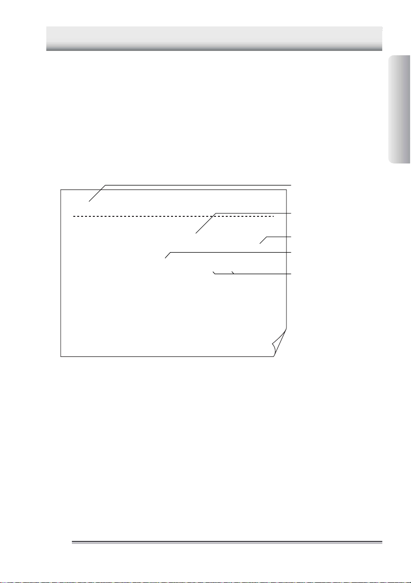
■ Collector function
The collector function is used when the measured temperature and measurement conditions
are recorded under the specified “tag”.
In the “tag”, the tag name (i.e. “what”), date and time (i.e. “when”), operator name (i.e. “who”),
and alarm (i.e. “judgment on the measured data”) are recorded as the measurement conditions, in addition to the measured temperature.
Tag name ("what")
[Burger]
No. Date Temp. Hi
00001 98/11/12/11:37:01 56.0
00002 98/11/12/11:37:01 57.5
00003 98/11/12/11:37:02 58.5
00004 98/11/12/11:37:03 59.8
00005 98/11/12/11:37:04 61.2
00006 98/11/12/11:37:04 62.0
00007 98/11/12/11:37:05 62.0
00008 98/11/12/11:37:06 70.0
00009 98/11/12/11:37:06 75.0
00010 98/11/12/11:37:07 81.0
00011 98/11/12/11:37:07 82.0
HiAlarm=+80.0 LoAlarm=+60.0
OK
OK
OK
OK
OK
OK
OK
OK
OK
NG
NG
Lo Person
Smith
NG
Smith
NG
Smith
NG
Smith
NG
Smith
OK
Smith
OK
Smith
OK
Smith
OK
Smith
OK
Smith
OK
Smith
OK
Measure
ment
temperature
Operator name ("who")
Date and time ("when")
Alarm
("measured data judgment")
NG = No Good
Information Required
before Use
Printout of image from a recommended printer
It is possible to use maximum 50 tags, and in these 50 tags, a total of 5,000 pieces of temperature measurement data can be recorded. However, the more the data is saved with the logging
function, the less number of measurements can be made with the collector function.
Set up the following tag items in advance to use the collector function.
•Tag name
• Input channel
• Alarm
• Operator name
See Also
For more information, refer to the “Preparation for Measurement” part.
IM 54051-E
11
Page 10

1 Features of This Product
■ Logging function
The logging function is used to automatically measure temperatures at given measurement
intervals and to continue to record the result data. This function is useful when a temperature
variation within a certain period of time (e.g. temperature variation in a refrigerator being
transported) needs to be recorded.
With this logging function, the temperatures and date (year/month/day) and time will be recorded as a “log”. Unlike the collector function, the logging function does not record the
operator name and alarm (measured data judgment).
Log name
[Convey ] Interval=00:00:10
No. Date Temp.
00001 00/00/00/00:00:00 -10.5
00002 00/00/00/00:00:10 -10.5
00003 00/00/00/00:00:20 -11.0
00004 00/00/00/00:00:30 -12.0
00005 00/00/00/00:00:40 -11.5
00006 00/00/00/00:00:50 -11.0
00007 00/00/00/00:01:00 -11.0
00008 00/00/00/00:01:10 -10.7
00009 00/00/00/00:01:20 -10.5
00010 00/00/00/00:01:30 -11.0
00011 00/00/00/00:01:40 -12.0
Printout of image from a recommended printer
Measurement interval
Temperature
Date and time
It is possible to use maximum 10 logs, and in these 10 logs, a total of 20,000 pieces of data
can be recorded. However, the more the data is saved with the collector function, the less
number of measurements can be made with the logging function.
Set up the following items in advance to use the logging function.
• Log name
• Input channel
• Measurement interval
• Measurement period
See Also
For more information, refer to the “Preparation for Measurement” part.
22
IM 54051-E
Page 11
2 Names and Functions of Each Part
2 Names and Functions of Each Part
A
➀
➅
➆
Bottom face
➁
D
RS232C
➂
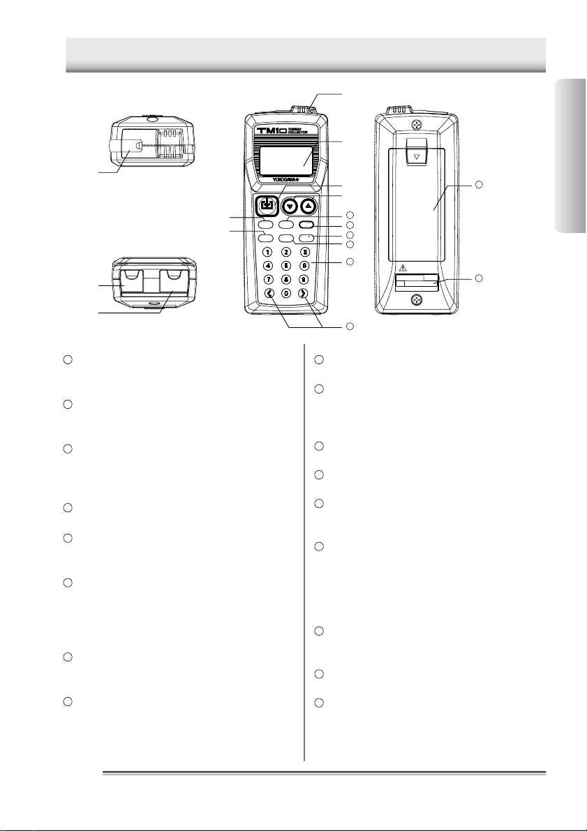
External probe connection jack (channel A)
1
Used to connect a needle-type standard probe, a
needle-type high-speed probe, or other probes.
Radiation temperature probe connec-
2
tion jack (channel D)
Used to connect a radiation thermometer.
RS-232C communication connection
3
terminal
Used to output data from this instrument to a personal computer or printer.
Built-in sensor (channel C)
4
Used to measure the external temperature.
Display (LCD)
5
Displays Thermo-Collector conditions, various setup
information, measurement temperature, etc.
[CH] key
6
Used to switch the current input channel. Available
input channels include channel A (for probes), channel C (for the built-in sensor), and channel D (for the
radiation temperature probe).
[ESC] key
7
Used to cancel the previous operation and return to
the previous screen.
[Memory] key
8
Used to commence a temperature measurement with
either the collector function or the logging function.
Front faceTop face
MEMORY
CH
ESC FUNC
PQRS
LOGGING
CLEAR
POWER
ABC DEF
JKLGHI MNO
Symbol
➃
Back face
➄
➇
➈
10
11
[▼] [▲] key
9
12
13
14
15
WARNING
NO.
Yokogawa M&C Corporation
Made in
Japan
SET
WXYZTUV
Used to select an appropriate tag, log, or function.
[LOGGING] key
10
Used to switch between the collector and logging
functions. Also used to modify alphanumeric characters from uppercase to lowercase.
[POWER] key
11
Used to turn the power supply on and off.
[Set] key
12
Used to make the setup contents valid for operation.
[Func] key
13
Used to set up the selected function.
Also used to delete the measurement data.
[1],...,[9], and [0] keys
14
Used to enter alphabets and numbers.
The [0] key is also used for switching the unit of temperature display. If, for example, this [0] key is
pressed in the Home screen, the unit is switched to
“F”. Another pressing of the same key will restore
the unit to “C”.
[<] and [>] keys
15
Used to retrieve the logged tag data or log data, or to
select the character input position.
Battery compartment
16
Accommodates two LR6 alkaline dry cells.
Name plate
17
Information Required
before Use
16
17
IM 54051-E
33
Page 12
3 Setting the Battery
3 Setting the Battery
Two LR6 alkaline dry cells are included with this instrument.
1. Open the battery compartment cover at the back of the main unit.
See Also
For information about the position of the battery compartment, refer to “2 Names and Functions of
Each Part”.
2. Observing the correct polarity, install the two LR6 alkaline dry cells in the battery com-
partment.
Caution
Observe the correct polarity when installing the batteries in the battery compartment.
The main unit may be damaged if the batteries are installed incorrectly.
3. Close the battery compartment cover.
-End of procedure-
Caution
Remove old batteries from the compartment. Battery liquid leakage may cause the
main unit to malfunction or may damage it. A “BatteryEmpty” message will appear on
the LCD shortly before the battery life expires. When this message appears, replace
the batteries.
44
IM 54051-E
Page 13

4 Turn ON/OFF of the Power Supply
4 Turn ON/OFF of the Power Supply
■ Turn the power supply to ON
Press the [POWER] key.
After the “TM10 Ver. 1.00”, “Initial Test”, and “Initial OK” messages have been displayed, the time display screen
appears on the LCD.
19:13:15
– –––––––
The power of the main unit is turned on.
■ Turn the power supply to OFF
Hold down the [POWER] key for about three seconds.
The power to the main unit will be shut down after a short beep has been sounded.
Information Required
before Use
IM 54051-E
55
Page 14
5 Screen (LCD) Displays
5 Screen (LCD) Displays
➄
➀
➁
➂
➃
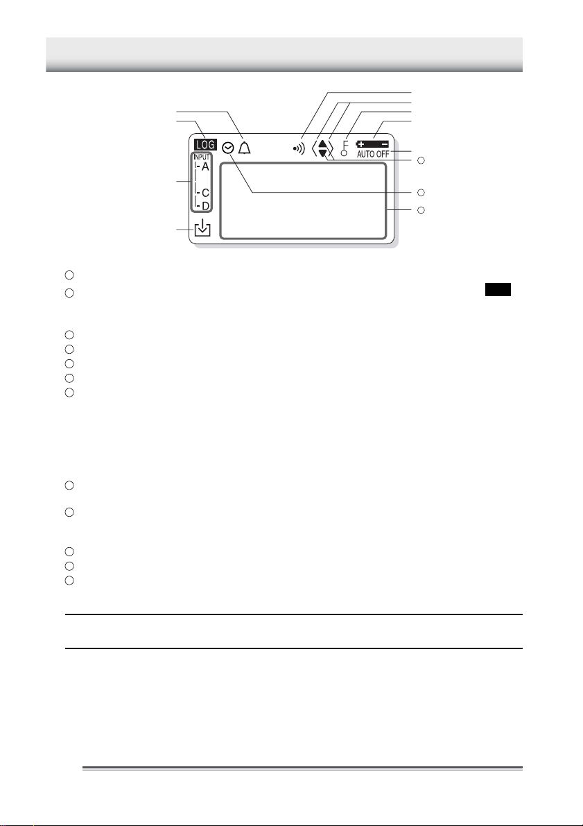
Indicates that the chime function is being set.
1
Indicates whether the current mode is the collector mode or logging mode. If LOG is
2
displayed, the current mode is the logging mode. If it is not displayed, the current mode is the collector mode.
Indicates the input channels currently used for measurement.
3
Indicates that the measurement data is being logged into the instrument.
4
Indicates that the alarm is set.
5
Indicates that either the [<] or [>] key can be used.
6
Indicates that either the key lock or FUNC lock is set. If the key lock function is
7
on, all the keys are disabled. In the FUNC lock state, only the temperature measurement keys can be used.
12:30:00
+028
.5 C
See Also
For information about canceling the lock state, refer to “5 Other Useful Functions” in the “Temperature Measurement” part.
Indicates that the battery is almost used up. Replace the battery as soon as
8
possible after this symbol is displayed.
Indicates that the instrument is set so that the power to the main unit will be
9
automatically turned off if no operation is made in a predetermined period of
time.
Indicates that either the [▲] or [▼] key can be used.
10
Indicates that the timer function is on and the instrument is in the wait state.
11
A tag name, log name, and temperature will be displayed.
12
➅
➆
➇
➈
10
11
12
[TIP]
If this instrument is used in a location where the ambient temperature is low, the characters may be
displayed slowly. Note that this does not indicate the main unit being at a malfunction.
66
IM 54051-E
Page 15
6 How to Input Characters
6 How to Input Characters
This section explains the character input procedure. Alphabets and n umbers can
be entered.
The procedure used to input characters into Thermo-Collector is similar to the
method used to enter characters in a cellular phone.
■ Entering characters
Use the 0 to 9 keys to enter characters. These keys are also used to enter alphabets.
2
For example, the
key three times.
To enter “2”, press the
Mode
Key
1
2
ABC
3
DEF
4
GHI
5
JKL
6
MNO
7
PQRS
8
TUV
9
WXYZ
0
Symbol
key can be used to enter “A” to “C”, and “2”. To enter “C”, press the
2
key four times.
Alphanumeric input mode
1
A B C 2
D E F 3
G H I 4
J K L 5
M N O 6
P Q R S 7
T U V 8
W X Y Z
0 ! # $ )& ( =+ -
%
9
Information Required
before Use
2
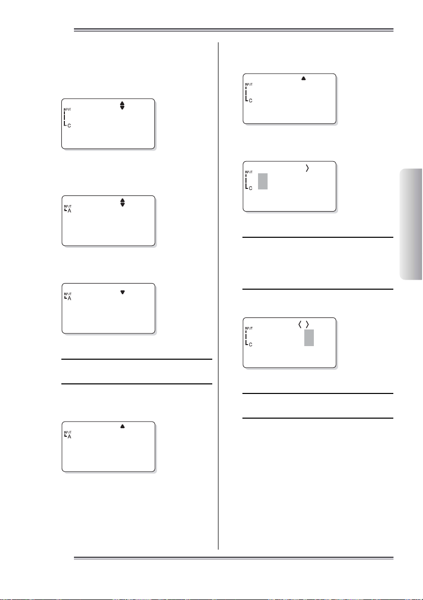
■ Entering lowercase characters
1. Enter a character to be made small.
A
[NewTag]
2. Position the cursor on the character and press the [LOGGING] key.
This character is made small.
a
[NewTag]
IM 54051-E
- End of procedure
77
Page 16
1 Overview of Preparation for Measurement
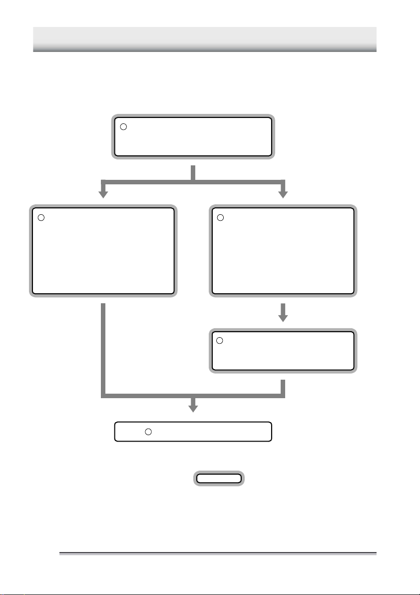
1 Overview of Preparation for Measurement
Before measuring temperatures, set the tag names, etc., on the main unit.
There are two methods for making the settings. One is for the main unit and the
other is for a personal computer. For efficiency, use a personal computer to set
many items.
Setting up the main unit
• Setting the date and time
• Setting the name of the main unit
Setting up the main unit Setting up the personal computer
Set up the following
• Collector function
Tag name, input channel, alarm,
and operator name
• Logging function
Log name, input channel,
measurement interval,
and measurement period
Measure the temperature
Set up the following
• Collector function
Tag name, input channel, alarm,
and operator name
• Logging function
Log name, input channel,
measurement interval,
and measurement period
Transmit the following data
• Setup data
• Operator name
: Setup to be performed in this part
88
IM 54051-E
Page 17
2 Setting Up the Main Unit
2 Setting Up the Main Unit
2.1 Setting the date and time
Home screen
18:54:27
22225.9°C
[TIP]
This screen which displays the current time is
referred to as the “Home” screen. All the functions in the main unit are accessed from this
screen.
1. Press the [FUNC], [6], and [1] keys, in
this order.
The “Time setting” screen will appear on the LCD.
F61
ClockSet
2. Press the [SET] key.
A screen for setting the date will appear on the LCD.
4. Press the [SET] key.
A screen for setting the time will appear on the LCD.
Time
18:56:14
5. Enter the time.
6. Press the [SET] key.
The specified time is set.
F61
ClockSet
Press the [ESC] key repeatedly to return to the Home
screen.
-End of procedure-
Preparation for
Measurement
Date
98/11/11
3. Enter the date.
See Also
For information about entering a character or
number, refer to “6 How to Input Characters”
in the “Information Required before Use” part.
IM 54051-E
9
99
Page 18

2 Setting Up the Main Unit
222
2.2 Setting the name of the
main unit
If more than one Thermo-Collector is used
at a time, a unique name must be set for each.
[TIP]
Make this setting as necessary.
Home screen
18:54:27
222
25.9°C
1. Press the [FUNC], [9], and [7] keys, in
this order.
The “Name” screen appears on the LCD.
F97
Name
2. Press the [SET] key.
4. Press the [SET] key.
The instrument name is set.
The “Name” screen will be restored.
F97
Name
Press the [ESC] key repeatedly to return to the Home
screen.
-End of procedure-
DevName
Name00---
3. Enter the name of the instrument (Ex-
ample: NO1).
DevNamee
NO1
See Also
For information about entering a character or
number, refer to “6 How to Input Characters”
in the “ Information Required before Use” part.
10
1010
IM 54051-E
Page 19

3 Setting Up with the Main Unit
3 Setting Up with the Main Unit
3.1 Setups required to use the collector function
(Setting the tag name, input channel, alarm, and operator name)
Before using the collector function, the following tag setups must be made.
■ Setup contents
●Tag name
Put a title for each tag.
●Input channel
Thermo-Collector has multiple input channels and probes for measuring temperatures of
substances in a vapor, solid, or liquid phase. Since the probe to be used depends on the
measuring object, it is necessary to set the available input channel on a tag in advance.
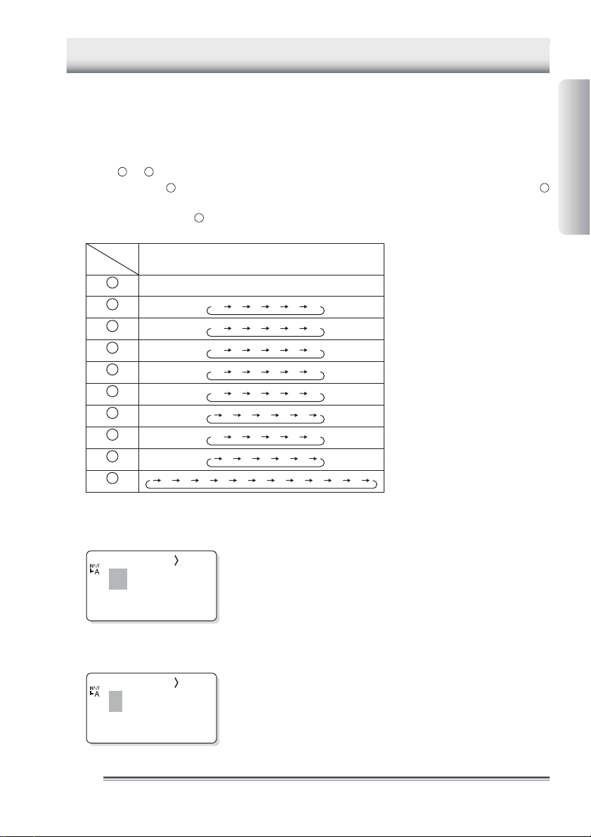
The following table shows the probe types and their corresponding input channels.
Probe type Input channel
Standard needle probe
High speed needle probe
Surface probe
Rounded end probe
Built-in sensor C
Emission thermo probe D
A
Preparation for
Measurement
●Alarm
Set a limit temperature at which the alarm sounds.
• ON/OFF of the upper-limit alarm and upper-limit temperature
Make the following settings to sound an alarm when the temperature rises above a preset limit.
The upper-limit temperature cannot be set if the alarm function for the upper limit is set to OFF.
Setting the upper-limit alarm to ON and the upper-limit temperature to 70°C
Temperature
70°C
: Range in which the alarm sounds.
IM 54051-E
1111
Page 20

3 Setting Up with the Main Unit
• ON/OFF of the lower-limit alarm and lower-limit temperature
Make the following settings to sound an alarm if the temperature falls below a preset limit.
The lower-limit temperature cannot be set if the alarm function for the lower limit is set to OFF.
Setting the lower-limit alarm to ON and the lower-limit temperature to 50°C
Temperature
50°C
: Range in which the alarm sounds
• Inverse alarm function ON/OFF
The settings of the alarm function can be inverted.
Specifically, if this inverse alarm functions is set to ON, an alarm will sound if the temperature falls
below the upper limit or if the temperature rises above the lower limit.
If “OFF”
Upper-limit alarm 70°C
Lower-limit alarm 50°C
Temperature
If “ON”
Upper-limit alarm 70°C
Lower-limit alarm 50°C
Temperature
70°C
50°C
: Range in which the alarm sounds
70°C
50°C
[TIP]
The alarm can also be set to turn off if the temperature exceeds the upper limit, or it can be set to turn
on if the temperature falls between the upper and lower limits.
●Operator name
Set the name of the operator.
See Also
For information about setting the operator name, refer to “■ Registering the measurement operator
name”.
12
1212
IM 54051-E
Page 21
3 Setting Up with the Main Unit
■ Creating a new tag
Create new tags for recording the measurement data.
Home screen
18:54:27
22225.9°C
1. Press the [FUNC], [1], and [3] keys, in
this order.
The “Ins” screen will appear on the LCD.
F13
Ta g Ins
2. Press the [SET] key.
A screen for selecting the tag name will appear.
Burger
0
[TIP]
If no tag has been created in the main unit,
[NewTag] is displayed on the screen.
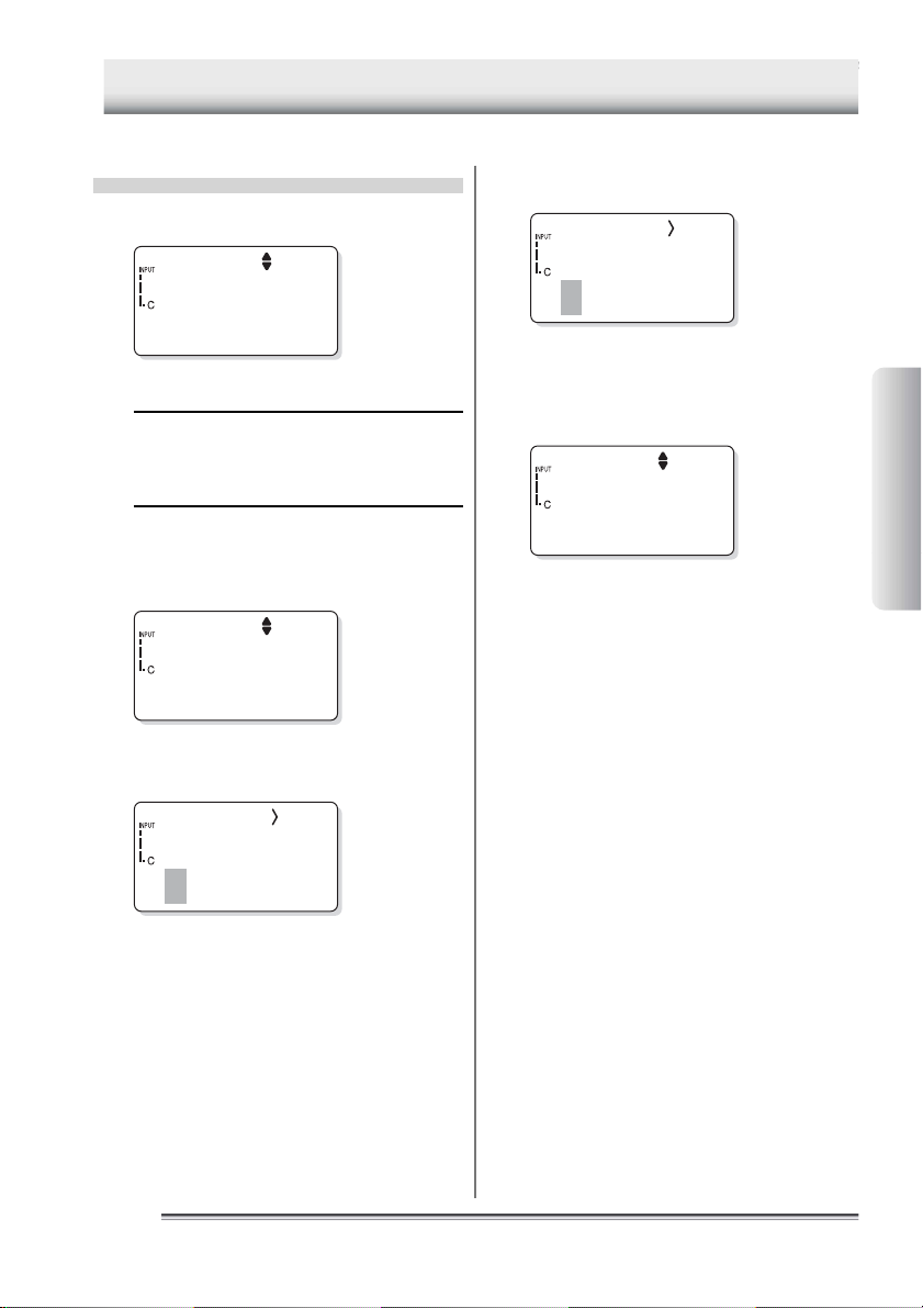
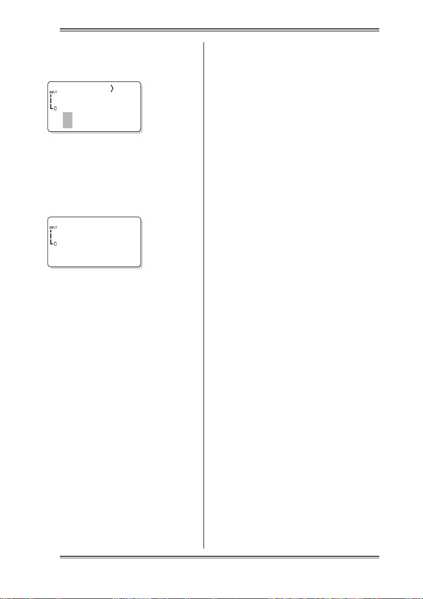
3. Press the [▼] key repeatedly until
[NewTag] is displayed on the screen.
4. Use the [CH] key to select the input
channel.
The input channel of the [INPUT] gage changes.
[NewT ag]
0
5. Press the [SET] key.
A screen for entering a new tag name will appear.
[NewTag]
[TIP]
If a new tag is created while [NewTag] is displayed, the created tag will be added to the end
of the list. If the [SET] key is pressed while
[NewTag] is not displayed, the created tag will
be inserted immediately before the selected tag.
6. Enter the tag name.
Convey
[NewTag]
[TIP]
A tag name can consist of a maximum of eight
alphanumeric characters.
Preparation for
Measurement
IM 54051-E
[NewT ag]
0
See Also
For information about entering a character or
number, refer to “6 How to Input Characters”
in the “ Information Required before Use” part.
13
1313
Page 22
3 Setting Up with the Main Unit
222
7. Press the [SET] key.
A screen for confirming the entered contents will appear.
Insert?
Yes1/No0
8. Press the [1] key.
A new tag will be created.
Convey
0
Press the [ESC] key repeatedly to return to the Home
screen.
-End of procedure-
■ Setting the alarm function for
each tag
The alarm function can be set according to
different tag conditions, or the same alarm
function can be set for all tags.
The following procedure is used to set the
alarm function for different conditions.
See Also
To set the same alarm function for all tags, proceed to “■ Batch-setting the alarm function”.
Home screen
1. Press the [FUNC], [7], and [2] keys, in
this order.
The “1File” screen will appear on the LCD.
F72
1File
2. Press the [SET] key.
A screen for selecting a tag name will appear.
Convey
0
3. Press the [▼] key repeatedly until a tag
name for which the alarm is to be set
appears on the screen.
4. Press the [SET] key.
A screen for setting the alarm HIGH function ON/
OFF will appear on the LCD.
Hi Alarm
ON
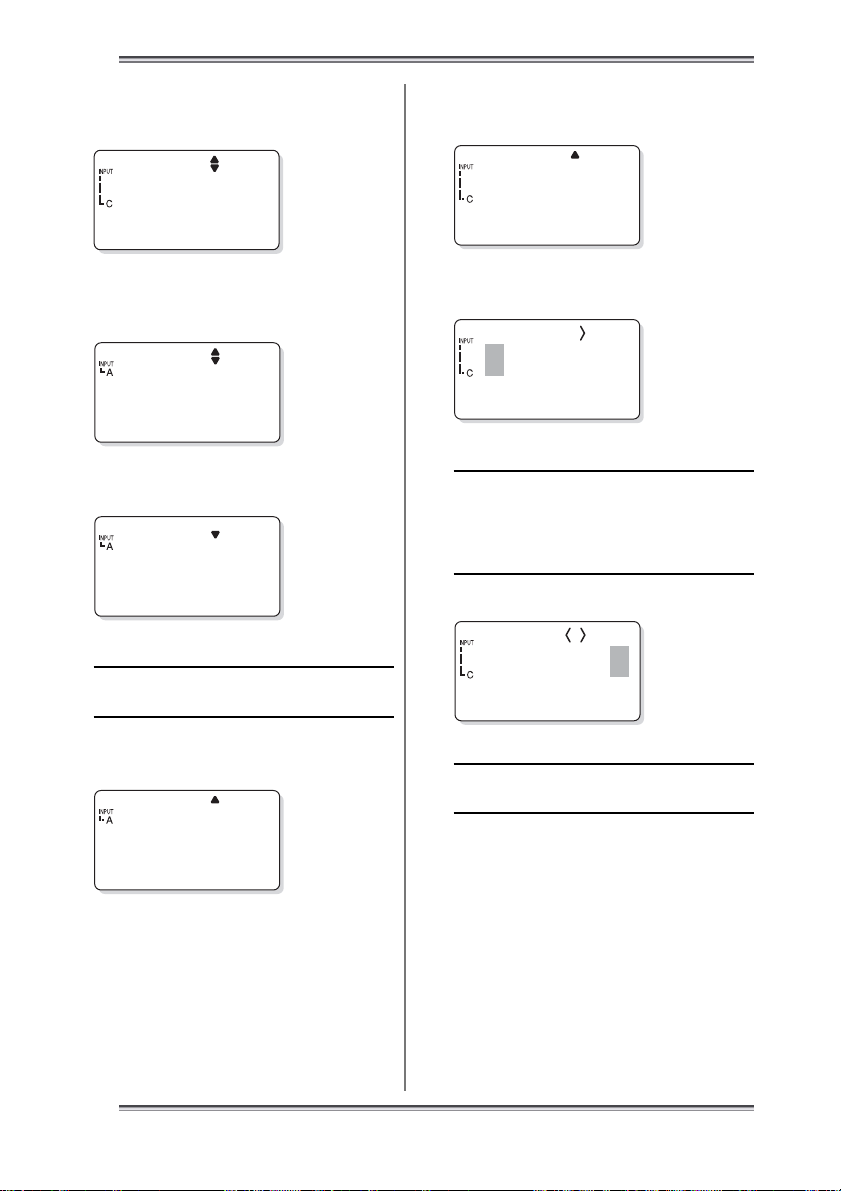
5. Use either the [▼] or [▲] key to set the
upper-limit temperature alarm function
ON/OFF.
14
1414
18:54:27
222
25.9°C
6. If ON has been selected, press the [SET]
key.
The “Hi Alarm” setting screen will appear on the
screen.
If OFF has been selected in step 5, this screen will
not appear. In this case proceed to step 8.
Hi Alarm
+000.0° C
IM 54051-E
Page 23

3 Setting Up with the Main Unit
7. Enter the upper-limit temperature.
Hi Alarm
+020.0° C
[TIP]
To set a negative value, press either the [▼] or
[▲] key. The “+” symbol on the screen will
change to a “-” symbol.
See Also
For information about entering a character or
number, refer to “6 How to Input Characters”
in the “ Information Required before Use” part.
8. Press the [SET] key.
The specified upper-limit temperature is set and the
screen to set the “Lo Alarm” function ON/OFF will
appear on the screen.
Lo Alarm
ON
9. Use either the [▼] or [▲] key to set the
lower-limit temperature alarm function
ON/OFF.
10
.
If “ON” has been selected, press the
[SET] key.
The “Lo Alarm” setting screen will appear on the
screen.
If “OFF” has been selected in step 9, this screen will
not appear. In this case proceed to step 12.
11
.
Enter the lower-limit temperature.
Lo Alarm
+020.0° C
[TIP]
To set a negative value, press either the [▼] or
[▲] key. The “+” symbol on the screen will
change to a “-” symbol.
12.Press the [SET] key.
The specified lower-limit temperature is set and the
“Inverse alarm function” screen will appear on the
screen.
Turn
OFF
13.Use either the [▼] or [▲] key to select
whether the operation of the alarm function is to be inverted. If ON is selected,
the alarm function will operate under the
inverse conditions.
14.Press the [SET] key.
The range in which the alarm sounds will be displayed.
Then, the screen for confirming the setting will appear.
Change?
Yes1/No0
Preparation for
Measurement
IM 54051-E
Lo Alarm
+000.0° C
15.Press the [1] key.
The alarm function will be set for each tag.
Press the [ESC] key repeatedly to return to the Home
screen.
-End of procedure-
15
1515
Page 24

3 Setting Up with the Main Unit
222
■ Batch-setting the alarm function
The following procedure is used to set the
same alarm function for all tags.
Home screen
18:54:27
222
25.9°C
1. Press the [FUNC], [7], and [1] keys, in
this order.
The “All File” screen appears on the LCD.
F71
All File
2. Press the [SET] key.
A screen for setting the alarm HIGH function ON/
OFF will appear.
Hi Alarm
ON
3. Use either the [▼] or [▲] key to set the
upper-limit temperature alarm function
ON/OFF.
4. If ON has been selected, press the [SET]
key.
The “Hi Alarm” setting screen will appear on the
screen.
If OFF has been selected in step 3, this screen will
not appear. In this case proceed to step 6.
5. Enter the upper-limit temperature.
Hi Alarm
+020.0° C
[TIP]
To set a negative value, press either the [▼] or
[▲] key. The “+” symbol on the screen will
change to a “-” symbol.
See Also
For the method of entering a character or number, refer to “6 How to Input Characters” in
the “Information Required before Use” part.
6. Press the [SET] key.
The specified upper-limit temperature is set and the
screen of selecting ON/OFF of the “Lo Alarm” function will appear on the screen.
Lo Alarm
ON
7. Use either the [▼] or [▲] key to select
ON/OFF of the lower-limit temperature
alarm function.
8. When ON has been selected, press the
[SET] key.
The “Lo Alarm” setting screen will appear on the
screen.
If OFF has been selected in step 7, this screen will
not appear. In this case proceed to step 10.
Lo Alarm
16
1616
Hi Alarm
+000.0° C
+000.0° C
IM 54051-E
Page 25
3 Setting Up with the Main Unit
18:54:27
22225.9°C
9. Enter the lower-limit temperature.
Lo Alarm
+020.0° C
[TIP]
In order to set a negative value, press either
the [▼] or [▲] key. The “+” symbol on the
screen will change to a “-” symbol.
10.Press the [SET] key.
The specified lower-limit temperature is set and the
“Turn” screen will appear on the screen.
Turn
OFF
11.Use either the [▼] or [▲] key to select
whether the operation of the alarm function is to be inverted. If ON is selected,
the alarm function will operate under the
inverse condition.
12
.
Press the [SET] key.
The range in which the alarm sounds will be displayed.
Then, the screen for confirming the settings will appear.
■ Registering the measurement
operator name
Home screen
1. Press the [FUNC], [8], and [3] keys, in
this order.
F83
Entry
2. Press the [SET] key.
A screen for registering an operator name will appear.
1
Smith
3. Press the [▼] key repeatedly until a
number assigned to the operator name
to be registered appears on the screen.
Preparation for
Measurement
Change?
Yes1/No0
13.Press the [1] key.
The range in which the alarm function is active will
be set for all tags as a batch.
Press the [ESC] key repeatedly to return to the Home
screen.
[TIP]
If another alarm function is batch-set for all
tags after one alarm function has been batchset, only the latest one will be effective.
IM 54051-E
-End of procedure-
2
[TIP]
Each operator name is assigned a unique registration number. A maximum of ten operators
can be registered in the main unit.
See Also
For information about entering a character or
number, refer to “6 How to Input Characters”
in the “ Information Required before Use” part.
17
1717
Page 26
3 Setting Up with the Main Unit
4. Press the [SET] key.
5. Enter the operator name with a maxi-
mum of eight characters.
2
See Also
For information about entering a character or
number, refer to “6 How to Input Characters”
in the “ Information Required before Use” part.
6. Press the [SET] key.
The screen for confirming the settings will appear.
Entry?
Yes1/No0
7. Press the [1] key.
The specified operator name has been set.
Press the [ESC] key repeatedly to return to the Home
screen.
-End of procedure-
18
1818
IM 54051-E
Page 27

3 Setting Up with the Main Unit
3.2 Setups required to use the logging function
(Setting the log name, input channel, measurement interval,
and measurement period)
Before using the logging function, it is necessary to make logs settings.
■ Setup contents
●Log name
Put a title to each log. A log name can consist of a maximum of eight alphanumeric characters.
●Input channel
Thermo-Collector is provided with multiple input channels and probes for measuring temperatures of substances in a vapor, solid, or liquid phase. Since the probe to be used depends on the measuring object, it is necessary to set the available input channel on a tag in
advance.
The following table shows the probe types and their corresponding input channels.
Probe type Input channel
Standard needle probe
High speed needle probe
Surface probe
Rounded end probe
Built-in sensor C
Emission thermo probe D
A
Preparation for
Measurement
●Measurement interval
Set an interval at which the temperature is periodically measured. The interval can be set to
between 1 second to 24 hours.
●Measurement period
Set a period through which the temperature is measured continuously. The period can be
set to between 1 second to 999 days.
IM 54051-E
19
1919
Page 28
3 Setting Up with the Main Unit
222
■ Operation procedure
Home screen
18:54:27
222
25.9°C
1. Press the [FUNC], [2], and [3] keys, in
this order.
The “Ins” screen will appear on the LCD.
F23
Log Ins
2. Press the [SET] key.
A screen for selecting the log name will appear.
Accept1
0
[TIP]
If no log has been created in the main unit,
[NewLog] is displayed on the screen.
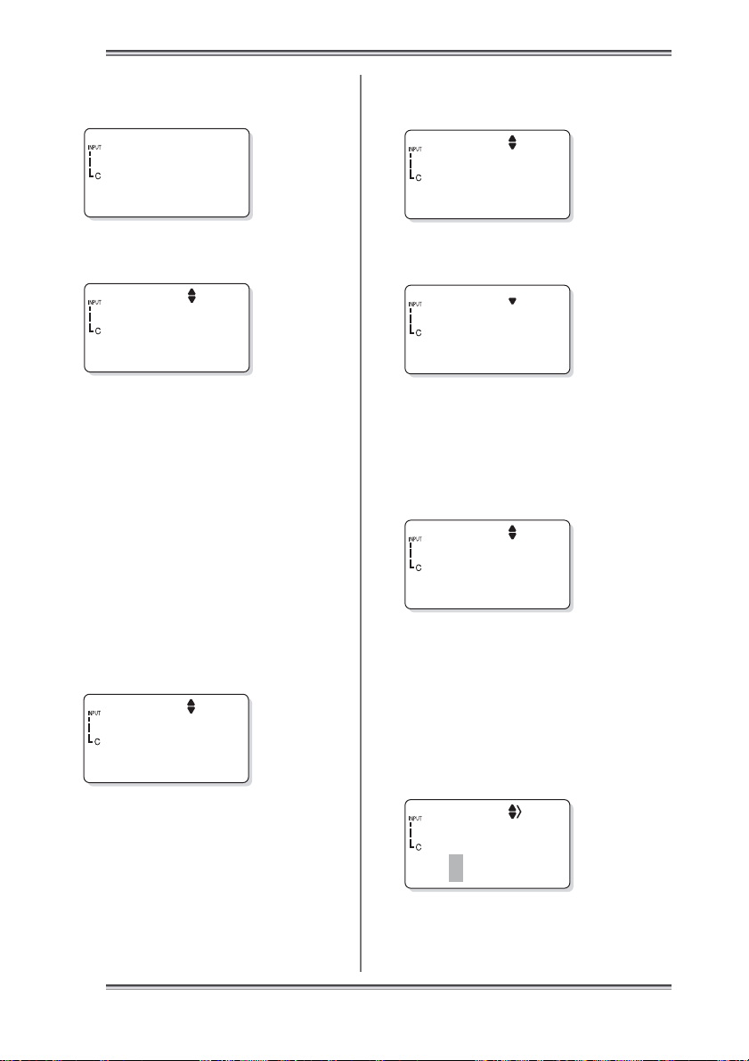
4. Use the [CH] key to select the input
channel.
The input channel of the [INPUT] gage changes.
[
NewLog
]
0
5. Press the [SET] key.
A screen for entering a new log name will appear.
[NewLog]
[TIP]
If a new log is created while [NewLog] is displayed, the created log will be added to the end
of the list. If the [SET] key is pressed while
[NewLog] is not displayed, the created log will
be inserted immediately before the selected log.
6. Enter the log name.
Accept2
[NewLog]
3. Press the [▼] key repeatedly until
[NewLog] appears on the screen.
[
NewLog
]
0
20
2020
[TIP]
A log name can consist of a maximum of eight
alphanumeric characters.
See Also
For information about entering a character or
number, refer to “6 How to Input Characters”
in the “ Information Required before Use” part.
IM 54051-E
Page 29

3 Setting Up with the Main Unit
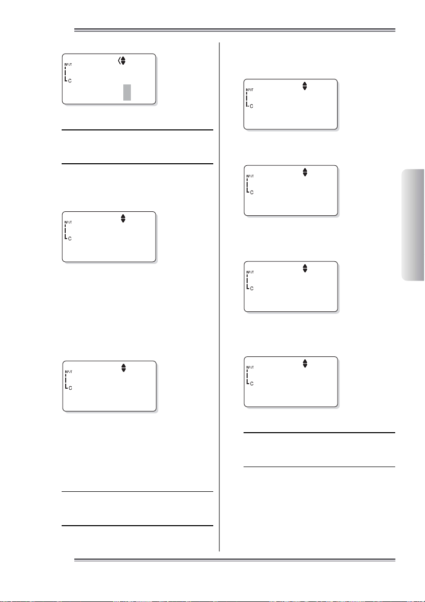
7. Press the [SET] key.
A screen for setting the measurement interval will appear.
Interval
00:00:10
8. Enter the hour, minute, and seconds.
Interval
01:15:30
[TIP]
The definition and range of each input value is
given below.
00:00:00
Indicates the seconds.
The input range is between 0
and 59 seconds
Indicates the minutes.
The input range is between 0
and 59 minutes
Indicates the hours.
The input range is between 0
and 24 hours.
9. Press the [SET] key.
The specified measurement interval is set and the
screen for setting the measurement period (select the
number of days from the options, which also includes
the number of hours, minutes, and seconds) will be
displayed.
11
.
Press the [SET] key.
The screen for setting the measurement period (select the
number of hours, minutes and seconds from the options,
which also includes the number of days) will be displayed.
ProdTime
00:00:00
12
.
Enter the number of hours, minutes, and
seconds.
ProdTime
01:30:00
[TIP]
The definition and range of each input value
are given below.
00:00:00
Indicates the seconds.
The input range is between 0
and 59 seconds
Indicates the minutes.
The input range is between 0
and 59 minutes
Indicates the hours.
The input range is between 0
and 23 hours.
13
.
Press the [SET] key.
The screen for confirming the settings will appear.
Insert?
Preparation for
Measurement
ProdDay
10
.
Enter the number of days.
IM 54051-E
002
Yes1/No0
14
.
Press the [1] key.
The specified measurement period has been set.
Accept2
0
Press the [ESC] key repeatedly to return to the Home
screen.
-End of procedure-
21
2121
Page 30

4 Setting Up with the Personal Computer
4 Setting Up with the Personal Computer
4.1 Setting up the “Thermo-Collector” software
The setup operation required for the main unit can be performed on a personal computer.
The “Thermo-Collector” software must be used to do this. This section explains the procedure used to set up the “Thermo-Collector” software on the personal computer.
Connecting the personal computer and the main unit
↓
Installing the “Thermo-Collector” software on the personal computer
↓
Confirming the communication environment (on the personal computer)
↓
Confirming the communication environment (on the main unit)
■ Connecting the personal computer and the main unit
Purchase an RS-232C cable (Model name: 910 09, round DIN 8-pin to D-sub 25-pin type).
Follow the procedure below to connect the main unit to the personal computer.
1. Turn off the power to both the personal computer and main unit.
2. Connect the personal computer and the main unit as shown in the following diagram.
2222
MEMORY
ESC FUNC SET
PQRS
Main unit
POWERCHLOGGING
ABC DEF
JKLGHI MNO
WXYZTUV
Symbol
D
Bottom of the
main unit (8-pin)
Personal computer
Dedicated cable (Model name: 910 09)
Connection between connector pins
(Round DIN 8-pin to D-sub 25-pin)
14
22
35
43
77
87
Serial port of the personal
computer (with 25-pin connector)
Plug this cable into the connector so that the
“ ” mark on the grip faces downward.
5, 6 (N.C.)
IM 54051-E
Page 31

4 Setting Up with the Personal Computer
[TIP]
If the personal computer has a 9-pin type serial port, a 25-pin to 9-pin conversion connector is required
(RS-232C conversion adapter, D09-9F25F (Manufacturer: Sanwa Supplies Corp.) is recommended).
3. First turn on the power to the main unit, then turn on the power to the personal com-
puter.
-End of procedure-
■ Installing the “Thermo-Collector” software
Install the “Thermo-Collector” software on the personal computer. The two floppy diskettes
that come with the main unit are required for this installation.
1. Place a floppy diskette (Setup Disk #1) in the floppy disk drive of the personal com-
puter.
2. Double-click on the “My Computer” icon.
The “My Computer” folder will be displayed.
Preparation for
Measurement
IM 54051-E
2323
Page 32

4 Setting Up with the Personal Computer
3. Double-click on the floppy disk drive icon (A:drive in the case of a DOS/V machine).
4. Double-click on “Setup”.
The Setup is initiated and a screen prompting the insertion of the second floppy diskette (Setup Disk #2) will appear.
5. After inserting the second floppy diskette (Setup Disk #2), click on the [OK] button.
Precautions to be observed prior to installation will appear.
6. Click on the [OK] button.
The installer of the application program is initiated and the “Thermo Collector Setup” screen will be displayed.
[Start Setup] button
2424
IM 54051-E
Page 33

4 Setting Up with the Personal Computer
7. Click on the [Start Setup] button.
[TIP]
Do as follows to change the application install destination.
1.Click on the [Change Directory] button.
2.Select a installation destination folder.
3.Click on the [OK] button.
After installation has been completed, the following confirmation window is displayed.
8. Click on the [OK] button.
-End of procedure-
■ Confirming the communication environment (on the personal computer)
Confirm the settings related to the communication environment on the personal computer.
1. Select “Thermo-Collector” in the “Programs” accessed from the “Start” menu.
2. Select “Properties” from the “Comm” menu.
The “Properties” window will be displayed.
3. Confirm that the settings are exactly as shown in the above figure.
If any of the settings are different, set them to the values given below.
Setup item Setting value
CommPort 1
Baud Rate 9600
Parity None
Data Bits 8
Stop Bits 2
[TIP]
The communication port setting values vary, depending on the type of personal computer. For more
information, refer to the manual supplied with your personal computer.
Preparation for
Measurement
IM 54051-E
-End of procedure-
25
2525
Page 34

4 Setting Up with the Personal Computer
222
■ Confirming the communication
environment (on the main unit)
Confirm the settings related to communication environment on the main unit. Confirm that the settings are exactly as shown
in the following table.
If any of the settings are different, set them
to the values given below.
Setup item Setting value (Factory Settings)
Baud rate 9600
Parity
Data Length 8bit
Stop bits 2bit
Flow control None
Home screen
None
18:54:27
222
25.9°C
1. Press the [FUNC], [5], and [1] keys, in
this order.
A screen for setting the communication environment
will appear on the LCD.
4. Press the [SET] key.
A screen for setting the data length will appear on the
LCD. Confirm that the displayed data length is as
shown in the following figure.
Data Len
8bit
5. Press the [SET] key.
A screen for setting the number of stop bits will appear on the LCD. The displayed number of stop bits
is 2 bits, which is factory setting.
Stop Bit
2bit
6. Press the [SET] key.
A screen for setting the flow control method will appear on the LCD. The displayed flow control method
is None, which is factory setting.
Flow
None
F51
Comm Set
2. Press the [SET] key.
A screen for setting the baud rate will appear on the
LCD. The displayed baud rate is 9600 bps, which is
factory setting.
Baudrate
3. Press the [SET] key.
A screen for setting the parity will appear on the LCD.
The displayed parity is None, which is factory setting.
Parity
26
2626
9600
None
7. Press the [SET] key.
Returns to the communication environment setup screen.
F51
Comm Set
Press the [ESC] key repeatedly to return to the Home
screen.
-End of procedure-
IM 54051-E
Page 35

4 Setting Up with the Personal Computer
4.2 Basic operation of Thermo-Collector software
This section explains the basic operation of the supplied software.
■ Initiating Thermo-Collector software
Select “Thermo-Collector” in the “Programs” accessed from the “Start” menu.
After the main screen of the software is displayed, the “Setup Tags/Logs - New” screen will be displayed.
Preparation for
Measurement
IM 54051-E
2727
Page 36

4 Setting Up with the Personal Computer
■ Terminating Thermo-Collector software
Select “Exit” from the “File” menu.
■ Saving the setup data in a file
1. Select “Save” in the “Setup Tags/Logs” menu accessed from the “File” menu.
The “Save As” window will be displayed.
2. Enter a file name in the “File name” field, then click on the [Save] button.
The setup data will be saved.
-End of procedure-
2828
IM 54051-E
Page 37

4 Setting Up with the Personal Computer
■ Loading a file containing the setup data
1. Select “Open” in the “Setup Tags/Logs” menu accessed from the “File” menu.
The “Open” window will be displayed.
2. Select a file to be loaded, then click on the [Open] button.
The specified file containing the setup data will be loaded, and the tag and log setup data in the file will be displayed.
Preparation for
Measurement
IM 54051-E
-End of procedure-
2929
Page 38

4 Setting Up with the Personal Computer
■ Saving the measurement operator name data
The operator data will be saved in a file different from that in which the tag and log data is
stored.
1. Select “Save” in the “Setup Persons” menu accessed from the “File” menu.
The “Save as” window will be displayed.
2. Enter a file name in the “File name” field, then click on the [Save] button.
The measurement operator name data being set will be saved.
-End of procedure-
3030
IM 54051-E
Page 39

4 Setting Up with the Personal Computer
■ Loading the measurement operator name file
1. Select “Open” in the “Setup Persons” menu accessed from the “File” menu.
The “Open” window will be displayed.
Preparation for
Measurement
2. Select a file to be loaded, then click on the [Open] button.
The measurement operator name file will be loaded, and a list of operator names will be displayed.
IM 54051-E
-End of procedure-
3131
Page 40

4 Setting Up with the Personal Computer
■ Other functions (Menu functions)
“Setup T ags/Logs” submenu
“Setup Persons” submenu
New
New
Creates a new file for setting up operator names.
Creates a new file for setting up operator names.
Open
Open
Opens a file in which operator names have been stored.
Opens a file in which operator names have been stored.
Save
Save
Overwrites a file in which operator names have been set.
Overwrites a file in which operator names have been set.
Save As
Save As
Saves a file in which operator names have been
Saves a file in which operator names have been
set under a new file name
set under a new file name
Close
Close
Closes the operator name setup screen.
Closes the operator name setup screen.
Send
Send
Transmits the operator name data file currently
Transmits the operator name data file currently
opened to the main unit.
opened to the main unit.
Print
Print
Outputs the operator name data for the printer.
Outputs the operator name data for the printer.
New
Creates a new setup file of tags and logs.
Open
Opens a file in which tags and logs have
been stored.
Save
Overwrites a file in which tags and logs
have been set.
Save As
Saves a file in which tags and logs have
been set under a new file name.
Send
Transmits the tag and log setup data to
the main unit.
Print
Outputs the tag and log setup data for
the printer.
“Measured Datas” submenu
3232
Save As
Saves the measurement data in a text format.
Close
Closes the measurement data file.
Transfer
Transfers the measurement data file to Excel.
Print
Outputs the measurement data to the printer.
IM 54051-E
Page 41

4 Setting Up with the Personal Computer
“Comm” menu
Properties
Set the conditions required to communicate with the personal
computer. Below are the setup items
• Communication port
• Baud rate
• Parity
• Data bits
• Stop bits
Receive
Receives from the main unit the measured temperature data and
other data set with the main unit.
“Edit” menu
Cut
Moves the currently selected data to the pasteboard.
Copy
Copies the currently selected data to the pasteboard.
Paste
Copies the data recorded in the pasteboard to the selected
location on the screen.
Delete
Deletes the currently selected data.
Select All
Sets all the data on the currently selected box to the selected
condition.
[TIP]
Measurement data received from the main unit cannot be edited using the “Edit” menu functions.
Preparation for
Measurement
“Display” menu
“Help” menu
IM 54051-E
Tool Bar
Switches on and off the toolbar display (button icon allowing
one-touch operation).
Status Bar
Switches on and off the status bar display (a region in which the
date and time are displayed).
About Thermo Collector...
Displays the version information of the Thermo-Collector
software.
33
3333
Page 42

4 Setting Up with the Personal Computer
■ Other functions (Tool icons functions)
For efficiency , single-click on any of the tool icons to instantly execute the assigned function.
Creates a new setup file of tags and logs.
This function is the same as “New” in the
“Setup Tags/Logs” submenu of the “File”
menu.
Loads a file of stored tags and logs. This
function is the same as “Open” in the “Setup
Tags/Logs” submenu of the “File” menu.
Saves the tag and log setup data file so it
overwrites the existing file. This function
is the same as “Save” in the “Setup Tags/
Logs” submenu of the “File” menu.
Transmits the tag and log setup data currently selected to the main unit. This function is the same as “Send” in the “Setup
Tags/Logs” submenu of the “File” menu.
Creates a new file for setting operator
names. This function is the same as “New”
in the “Setup Persons” submenu of the
“File” menu.
Loads the operator name file that has been
saved. This function is the same as “Open”
in the “Setup Persons” submenu of the
“File” menu.
Saves the operator name file so it overwrites
the existing file. This function is the same
as “Save” in the “Setup Persons” submenu
of the “File” menu.
Saves the measured data in a text format file.
This function is the same as “Save As” in
the “Measured Datas” submenu of the “File”
menu.
Transfers the measurement data which is
going to the personal computer to Microsoft
Excel. This function is the same as “Transfer” in the “Measured Datas” submenu of
the “File” menu.
Outputs the measurement data received in
association with the specified tag and log
to the printer. This function is the same as
“Print” in the “Measured Datas” submenu
of the “Comm” menu.
Receives the data from the main unit. This
function is the same as “Receive” in the
“Comm” menu.
Moves the currently selected data to the
pasteboard. This function is the same as
“Cut” in the “Edit” menu.
Copies the currently selected data to the
pasteboard. This function is the same as
“Copy” in the “Edit” menu.
Copies the data recorded in the pasteboard
to the currently selected location on the
screen. This function is the same as “Paste”
in the “Edit” menu.
34
3434
Transmits the operator name data currently
displayed on the screen to the main unit.
This function is the same as “Send” in the
“Setup Persons” submenu of the “File”
menu.
IM 54051-E
Page 43

4 Setting Up with the Personal Computer
4.3 Setups required to use the collector function
(Setting the tag name, input channel, alarm, and operator
name)
Make tag settings before using the collector function.
■ Setup contents
See Also
For information about each setup item, refer to “3.1 Setups required to use the collector function
(Setting the tag name, input channel, alarm, and operator name)”.
• Tag name
• Input channel
• Alarm
• Operator name
■ Setting tags
1. Initiate the “Thermo-Collector” software.
After the main screen of the “Thermo-Collector” software has been displayed, the “Setup Tags/Logs - New” screen
will appear.
Preparation for
Measurement
2. Enter the tag name in the “Name” field with a maximum of eight alphanumeric charac-
ters (Example: Burger).
[TIP]
A piece of setup data with an empty “Name” field cannot be transmitted to the main unit. Always enter
a name for setup data to be transmitted.
IM 54051-E
3535
Page 44

4 Setting Up with the Personal Computer
3. Double-click in the “Channel” column.
The specified tag name is set and the pull-down menu will appear.
4. Select either A, C, or D.
The specified channel is set.
5. Click in the “Hi Temperature” column
The cursor moves to a cell for the “Hi Temperature”.
6. Enter the “Hi Temperature” with numeric characters (-999.9 to +999.9; Example: +091.0).
[TIP]
Enter a value that does not exceed “Hi temperature” of the probe used for actual measurement. The
“Hi Temperature” that can be measured varies according to the probe used for measurement.
The specified upper-limit temperature has been set.
3636
IM 54051-E
Page 45

4 Setting Up with the Personal Computer
7. Double-click in the “Hi Alarm” column.
The pull-down menu will appear.
8. Select either ON or OFF.
9. Click in the “Lo Temperature” column.
The upper-limit alarm ON/OFF setting is made and the cursor moves to the “Lo Temperature” column.
10
.
Enter the “Lo Temperature” with numeric characters (-999.9 to +999.9; Example: +021.0).
[TIP]
Enter a value that does not fall below the “Lo Temperature” of the probe used for the actual measurement. The “Lo T emperature” that can be measured varies according to the probe used for the measurement.
Preparation for
Measurement
The specified lower-limit temperature has been set.
11
.
Double-click in the “Lo Alarm” column.
The pull-down menu will appear.
IM 54051-E
3737
Page 46

4 Setting Up with the Personal Computer
12
.
Select either ON or OFF.
The lower-limit alarm ON/OFF setting is made.
13
.
Click in the “Turn Alarm” column.
The pull-down menu will appear.
14
.
Select either ON or OFF.
The alarm condition is set.
If multiple tags have to be set, select the “Name” field in the next line, then repeat steps 2 through 14.
Subsequently, set the operator name.
3838
-End of procedure-
IM 54051-E
Page 47

4 Setting Up with the Personal Computer
■ Setting the measurement operator name
1. Select “New” from the “Setup Persons” submenu of the “File” menu.
A box for setting the Person name will appear.
2. In the “Person” field, enter the operator name with a maximum of eight alphanumeric
characters (Example: Smith).
Preparation for
Measurement
3. Click in the “Person” field on the next line.
The Persons name is set.
If multiple Person names have to be set, select the next line and repeat steps 1 through 3.
IM 54051-E
-End of procedure-
3939
Page 48

4 Setting Up with the Personal Computer
4.4
Setups required to use the logging function
(Setting the log name, input channel, measurement interval,
and measurement period)
Settings relating to the logging function must be made here.
■ Setup contents
See Also
For more information about each setup item, refer to “3.2 Setups required to use the logging function
(Setting the log name, input channel, measurement interval, and measurement period)”.
• Log name
• Input channel
• Measurement interval
• Measurement period
■ Operation procedure
1. Double-click on the “Logs” tab.
The log file setup screen will appear.
2. In the “Name” field, enter the tag name using a maximum of eight alphanumeric char-
acters (Example: Convey).
The specified log name is set
[TIP]
A piece of setup data with an empty “Name” field cannot be transmitted to the main unit. Always enter
a name for setup data to be transmitted.
4040
IM 54051-E
Page 49

3. Double-click in the “Channel” column.
The pull-down menu will appear.
4 Setting Up with the Personal Computer
4. Select either A, C, or D.
The specified channel is set.
5. Click in the “Measuring interval” column.
The cursor moves to a cell for the measurement interval.
6. Enter the measurement interval with numeric characters and colons “:” (Example:
00:10:00).
[TIP]
Use numeric characters and colons to enter a measurement interval. The input range is: hh < 25, mm
< 60, and ss < 60, where “hh” denotes hours, “mm” denotes minutes, and “ss” denotes seconds.
All the interval data must be eight characters or less (i.e. “hh:mm:ss”. h, m, and s are optional numeric
characters).
The specified measurement interval has been set.
Preparation for
Measurement
IM 54051-E
4141
Page 50

4 Setting Up with the Personal Computer
7. Click in the “Measuring period” column.
The cursor moves to a “Measuring period” field.
8. Enter the measurement period with numeric characters, a backslash, and colons
(Example: 003/20:30:00).
[TIP]
Use numeric characters, a backslash, and colons to enter a measurement period. The input range is:
ddd < 1000, hh < 24, mm < 60, and ss < 60, where “ddd” denotes the number of days, “hh” denotes
hours, “mm” denotes minutes, and “ss” denotes seconds.
All the period data must be twelve characters or less (i.e. “ddd:hh:mm:ss”. d, h, m, and s are optional
numeric characters).
The specified measurement period has been set.
If multiple tags have to be set, select a “Name” cell from the next line, then repeat steps 2 through 8.
-End of procedure-
4242
IM 54051-E
Page 51

4 Setting Up with the Personal Computer
4.5 Transmitting the setup data to the main unit
If the setup operation for the personal computer has been completed, transmit the setup data
of the tag, log, and operator name to the main unit.
Tag setup data and log setup data will be transmitted in a batch and as one file. The operator
data will be transmitted separately.
NOTE
If the setup data is transmitted to the main unit, the setup data and measurement data
that existed in the main unit before transmission will be deleted.
■ Preparation for transmission
1. Confirm that the power to the personal computer and main unit is OFF.
2. Connect the personal computer and main unit with the supplied cable.
See Also
For information about connecting the personal computer and main unit, refer to “■ Connecting the
personal computer and main unit” in section 4.1.
3. Turn on the power of the main unit.
See Also
For information about turning on the power to the main unit, refer to “4 Turn ON/OFF of the Power
Supply” in the “Information Required before Use” part.
Preparation for
Measurement
4. Turn on the power of the personal computer.
Now it is ready for transmission.
IM 54051-E
-End of procedure-
4343
Page 52

4 Setting Up with the Personal Computer
■ Transmitting the tag and log setup data to the personal computer
1. Initiate Thermo-Collector software.
After the main screen of Thermo-Collector software has been displayed, the “Setup T ags/Logs - New” screen will be
displayed.
2. Load a file in which the tag and log setup data is stored.
See Also
For information about loading a file containing tag and log data, refer to “■ Loading a file containing
the setup data” in section 4.2.
3. Select “Send” in the “Setup Tags/Logs” submenu accessed from the “File” menu.
The confirmation dialog box will appear.
4444
IM 54051-E
Page 53

4 Setting Up with the Personal Computer
4. Click on the [OK] button.
A dialog box indicating the progress of data transmission will be displayed. At the same time, “Sending...” is
displayed on the main unit.
After the transmission of the tag and log setup data has been completed, the screen indicating the progress of data
transmission and the screen displaying the “Comm...” message on the main unit will disappear.
-End of procedure-
■ Transmitting the measurement operator name data
1. Load a file in which the operator name to be transmitted is stored.
See Also
For information about loading a file containing operator names, refer to “■ Loading a file containing
the setup data” in section 4.2.
2. Select “Send” in the “Setup Persons” menu accessed from the “File” menu.
A dialog box indicating the progress of transmission will be displayed.
At the same time, “Comm...” is displayed on the main unit.
Preparation for
Measurement
After the transmission of the operator data has been completed, the screen indicating the progress of data transmission and the screen displaying the “Comm...” message on the main unit will disappear.
-End of procedure-
IM 54051-E
4545
Page 54

5 Confirm, Modify, Clear, or Delete the Data with the Main Unit
222
5
Confirm, Modify, Clear , or Delete the Data with the Main Unit
5.1 Confirming the number of
pieces of tag data
This section explains the procedure for confirming the number of pieces of tag data.
Home screen
18:54:27
222
25.9°C
1. Press the [FUNC], [1], and [1] keys, in
this order.
The “Curr tag” screen appears on the LCD.
F11
Curr Tag
2. Press the [SET] key.
Burger
12
5.2 Modifying the tag name
This section explains the procedure for modifying the tag name.
Home screen
18:54:27
22225.9°C
1. Press the [FUNC], [1], and [2] keys, in
this order.
The “TagChnge” screen appears on the LCD.
F12
TagChnge
2. Press the [SET] key.
Burger
12
3. Press the [▼] key repeatedly until the tag to
be confirmed is displayed on the screen.
The tag name and the measurement data recorded in
association with the tag will be displayed.
Beef
5
Press the [ESC] key repeatedly to return to the Home
screen.
-End of procedure-
46
4646
3. Press the [▼] key repeatedly until the
tag to be modified is displayed on the
screen.
Beef
5
4. Use the [CH] key to select the input
channel.
The input channel of the [INPUT] gage is modified.
IM 54051-E
Page 55

5 Confirm, Modify, Clear, or Delete the Data with the Main Unit
18:54:27
22225.9°C
5. Press the [SET] key.
Beef
5
6. Enter a new tag name to be modified.
Pork
5
[TIP]
A tag name that has not been modified will be
displayed. If it needs to be modified, overwrite
it with a new tag name.
See Also
For information about entering a character or
number, refer to “6 How to Input Characters”
in the “ Information Required before Use” part.
7. Press the [SET] key.
The confirmation dialog box will appear.
5.3 Clearing the measurement
data associated with the tag
This section explains the procedure used to
clear the measurement data obtained with the
collector function. However, the setup data
(tag name) will not be cleared.
Home screen
1. Press the [FUNC], [4], and [1] keys, in
this order.
The “1TagFile” screen appears on the LCD.
F41
1TagFile
2. Press the [SET] key.
Burger
Preparation for
Measurement
Change?
Yes1/No0
8. Press the [1] key.
The tag name after modification will be displayed.
Pork
The tag name has been modified.
Press the [ESC] key repeatedly to return to the Home
screen.
IM 54051-E
5
-End of procedure-
12
3. Press the [▼] key repeatedly until a tag
with measurement data that is to be
cleared is displayed on the screen.
Chicken
27
4. Press the [SET] key.
The confirmation dialog box will appear.
TagClr?
Yes1/No0
47
4747
Page 56

5 Confirm, Modify, Clear, or Delete the Data with the Main Unit
222
5. Press the [1] key.
Chicken
0
All the measurement data of the selected tag will be
cleared.
Press the [ESC] key repeatedly to return to the Home
screen.
-End of procedure-
5.4 Deleting the tag
This section explains the procedure used to
delete the tag from the main unit.
Note
Before deleting the tag, save the measurement data associated with the tag
to a personal computer, etc.
Once the tag has been deleted, all the
measurement data associated with the
tag will be completely lost.
See Also
For information about the procedure used to
save the measurement data, refer to “1 Receiving the Data on the Personal Computer” in the
“Utilizing the Measurement Data” part.
Home screen
1. Press the [FUNC], [1], and [4] keys, in
this order.
The “Tag Del” screen appears on the LCD.
F14
Ta g Del
2. Press the [SET] key.
Burger
12
3. Press the [▼] key repeatedly until the
tag to be deleted is displayed on the
screen.
Chicken
0
4. Press the [SET] key.
The confirmation dialog box will appear.
Delete?
Yes1/No0
48
4848
18:54:27
222
25.9°C
5. Press the [1] key.
The selected tag and its associated measurement data
will be deleted.
Press the [ESC] key repeatedly to return to the Home
screen.
-End of procedure-
IM 54051-E
Page 57

5 Confirm, Modify, Clear, or Delete the Data with the Main Unit
18:54:27
22225.9°C
5.5 Confirming the log setup
data
This section explains the procedure used to
confirm the log setup data.
Home screen
18:54:27
22225.9°C
1. Press the [FUNC], [2], and [1] keys, in
this order.
The “Curr Log” screen appears on the LCD.
F21
Curr Log
2. Press the [SET] key.
Convey
12
3. Press the [▼] key repeatedly until the
log to be confirmed is displayed on the
screen.
Accept
0
5. Press the [SET] key.
The current period (the number of days selected from
the options, including also the number of hours, minutes, and seconds) will be displayed.
ProdDay
2
6. Press the [SET] key.
The current period (the number of hours, minutes,
and seconds from the options including also the number of days) will be displayed.
ProdTime
00:00:30
[TIP]
If the [SET] key is pressed, the screen used to
confirm the interval set in step 4 is restored.
Press the [ESC] key repeatedly to return to the Home
screen.
-End of procedure-
5.6 Modifying the log name
and setup data (measurement interval and period)
This section explains the procedure used to
modify the log name, measurement interval,
and measurement period.
Home screen
Preparation for
Measurement
4. Press the [SET] key.
The current interval will be displayed.
Interval
00:00:10
IM 54051-E
49
4949
Page 58

5 Confirm, Modify, Clear, or Delete the Data with the Main Unit
1. Press the [FUNC], [2], and [2] keys, in
this order.
The “LogChnge” screen appears on the LCD.
F22
LogChnge
2. Press the [SET] key.
A screen for selecting a log will be displayed.
Convey
12
3. Press the [▼] key repeatedly until the
log to be modified is displayed on the
screen.
Accept
0
4. Use the [CH] key to select the input
channel.
The input channel of the [INPUT] gage is modified.
6. Enter a new log name to be modified.
Carry
0
[TIP]
•A log name can consist of a maximum of
eight alphanumeric characters.
•A tag name that has not been modified is
displayed on the screen. If it needs to be
modified, overwrite it with a new tag name.
See Also
For information about entering a character or
number, refer to “6 How to Input Characters”
in the “ Information Required before Use” part.
7. Press the [SET] key.
A screen for modifying the measurement interval will
appear.
Interval
00:00:10
8. Enter the hours, minutes, and seconds.
5. Press the [SET] key.
A screen for modifying the log name will be displayed.
Accept
0
50
5050
Interval
00:00:30
[TIP]
The definition and range of each input value is
given below.
00:00:00
Indicates the seconds.
The input range is between 0
and 59 seconds
Indicates the minutes.
The input range is between 0
and 59 minutes
Indicates the hours.
The input range is between 0
and 24 hours.
IM 54051-E
Page 59

5 Confirm, Modify, Clear, or Delete the Data with the Main Unit
9. Press the [SET] key.
The measurement interval is modified and a screen for
modifying the measurement period (the number of days
from the options, which also includes the number of
hours, minutes, and seconds) will be displayed.
ProdDay
000
10
.
Enter the number of days.
[TIP]
Between 0 and 999 days can be inputted.
11
.
Press the [SET] key.
A screen for modifying the measurement period (the
number of hours, minutes, and seconds from the options, which also includes the number of days) will
be displayed.
ProdTime
00:00:30
12
.
Enter the number of hours, minutes, and
seconds.
13
.
Press the [SET] key.
The confirmation dialog box will appear.
Change?
Yes1/No0
14
.
Press the [1] key.
The measurement period has been set.
Carry
0
Press the [ESC] key repeatedly to return to the Home
screen.
-End of procedure-
Preparation for
Measurement
ProdTime
00:00:45
[TIP]
The definition and range of each input value is
given below.
00:00:00
Indicates the seconds.
The input range is between 0
and 59 seconds
Indicates the minutes.
The input range is between 0
and 59 minutes
Indicates the hours.
The input range is between 0
and 23 hours.
IM 54051-E
51
5151
Page 60

5 Confirm, Modify, Clear, or Delete the Data with the Main Unit
222
5.7 Clearing the measurement
data associated with the log
This section explains the procedure for clearing the measurement data obtained with the
logging function. However, the setup data
(log name, measurement interval, and measurement period) will not be cleared.
Home screen
18:54:27
222
25.9°C
1. Press the [FUNC], [4], and [2] keys, in
this order.
The “1LogFile” screen appears on the LCD.
F42
1LogFile
2. Press the [SET] key.
Convey
12
3. Press the [▼] key repeatedly until a log
with measurement data that is to be
cleared is displayed on the screen.
5. Press the [1] key.
Accept
0
All the measurement data of the selected log will be
cleared.
Press the [ESC] key repeatedly to return to the Home
screen.
-End of procedure-
5.8 Deleting the log
This section explains the procedure used to
delete the log from the main unit.
Note
Before deleting the log, save the measurement data associated with the log
to a personal computer, etc.
If the log has already been deleted, all
the measurement data associated with
the log will be completely lost.
See Also
For information about the procedure used to
save the measurement data, refer to “1 Receiving the Data on the Personal Computer” in the
“Utilizing the Measurement Data” part.
Home screen
18:54:27
Accept
4. Press the [SET] key.
The confirmation dialog box will appear.
LogClr?
Yes1/No0
52
5252
22225.9°C
3
IM 54051-E
Page 61

5 Confirm, Modify, Clear, or Delete the Data with the Main Unit
18:54:27
22225.9°C
1. Press the [FUNC], [2], and [4] keys, in
this order.
The “Log Del” screen appears on the LCD.
F24
Log Del
2. Press the [SET] key.
Convey
12
3. Press the [▼] key repeatedly until the
log to be deleted is displayed on the
screen.
Accept
0
4. Press the [SET] key.
The confirmation dialog box will appear.
5.9 Batch-clearing the mea-
surement data associated
with both the tag and log
This section explains the procedure used to
clear all the measurement data associated
with both the tag and log. However, note
that the setup data will not be cleared.
Home screen
1. Press the [FUNC], [4], and [4] keys, in
this order.
The “All File” screen appears on the LCD.
F44
All File
2. Press the [SET] key.
Preparation for
Measurement
Delete?
Yes1/No0
5. Press the [1] key.
The selected log and its associated measurement data
will be deleted.
Press the [ESC] key repeatedly to return to the Home
screen.
IM 54051-E
-End of procedure-
DataClr?
Yes1/No0
3. Press the [1] key.
All the measurement data recorded in the main unit
will be cleared.
Press the [ESC] key repeatedly to return to the Home
screen.
-End of procedure-
53
5353
Page 62

5 Confirm, Modify, Clear, or Delete the Data with the Main Unit
222
5.10
Initializing the main unit
This section explains the procedure used to
initialize the main unit.
Note
Before initializing the main unit, it is recommended to save the setup data and
measurement data in the main unit to a
personal computer, etc.
When the main unit is initialized, all the
setup data and measurement data recorded in the main unit will be lost. However, the instrument name, chime setup,
and time setup data will not be erased.
See Also
For information about the procedure used to
save the measurement data, refer to “1 Receiving the Data on the Personal Computer” in the
“Utilizing the Measurement Data” part.
Home screen
18:54:27
222
25.9°C
3. Press the [1] key.
The initialization process begins.
Initia··
In two minutes, all the data set in the main unit will be
erased and the “Initial” screen will be restored,
Press the [ESC] key repeatedly to return to the Home
screen.
-End of procedure-
5.11
Confirming the current operator name
This section explains the procedure used to
confirm the operator name currently set.
Home screen
18:54:27
22225.9°C
1. Press the [FUNC], [8], and [1] keys, in
this order.
The “CurrData” screen appears on the LCD.
1. Press the [FUNC], [0], and [1] keys, in
this order.
The “Initial” screen appears on the LCD.
F01
Initial
2. Press the [SET] key.
Initial?
Yes1/No0
54
5454
F81
CurrData
2. Press the [SET] key.
The operator name currently set will be displayed.
1
Smith
Press the [ESC] key repeatedly to return to the Home
screen.
-End of procedure-
IM 54051-E
Page 63

5 Confirm, Modify, Clear, or Delete the Data with the Main Unit
5.12
Modifying the operator
This section explains the procedure used to
switch the currently set operator.
Home screen
18:54:27
22225.9°C
1. Press the [FUNC], [8], and [2] keys, in
this order.
The “Change” screen appears on the LCD.
F82
Change
2. Press the [SET] key.
A screen for modifying the operator will be displayed.
Preparation for
Measurement
1
Smith
3. Press the [▼] key repeatedly until the
operator to be modified is displayed on
the screen.
Operator names assigned to numbers between 1 and
10 will be sequentially displayed.
2
White
4. Press the [SET] key.
The operator set on the main unit will be changed.
Press the [ESC] key repeatedly to return to the Home
screen.
-End of procedure-
IM 54051-E
55
5555
Page 64

1 Input Channel and Probe
1 Input Channel and Probe
When measuring temperatures with Thermo-Collector, it is necessary to use an
appropriate input channel and probe. By combining these items in different ways,
it is possible to measure the temperature of various objects. The temperature of
air (gases), the surface and center of a solid, and various types of liquids can be
measured.
For example, the “C” input channel (built-in sensor of the main unit) is used to
measure the ambient air temperature. To measure the temperature at the center
of a hamburger , connect a needle-type standar d probe to the “A” measuring channel. To measure the surface temperature of a steel plate, connect a radiation
temperature probe to the “D” input channel.
The following table shows the available probe types, their corresponding input
channels, and the positions of connection jacks.
Probe (option) type Input channel Position of connection jack
Standard needle probe (Model name: 900 01)
High speed needle probe (Model name: 900 11)
Surface probe (Model name: 900 12)
Rounded end probe (Model name: 900 13)
Built-in sensor C Built into the main unit
Emission thermo probe (Model name: 900 03)
Warning
A
D
Left side of the top face (position marked “A” on the cover)
Left side of the bottom face (position marked “D” on the cover)
Do not point the tip of a needle-type standard probe or needle-type high-speed probe
towards somebody. The needle tip is very sharp and can cause injury.
Caution
• Handle the needle-type standard probe and needle-type high-speed probe carefully
so that its stylus is only put into the intended measuring object.
• Do not use this instrument in a location where it may be splashed or dropped in
water, otherwise it may malfunction.
5656
IM 54051-E
Page 65

1 Input Channel and Probe
Needle-type standard probe
MEMORY
POWER
CH
LOGGING
ESC FUNC
SET
ABC DEF
JKLGHI MNO
WXYZYUV
PQRS
Symbol
An example of the needle-type standard probe connected to input channel “A”
Note
Only connect a probe to input channel “A” if the power to the main unit is off or if the
home screen is being displayed. If the probe is connected to the channel after a tag
has been selected, this instrument may start having data logged into it the moment the
connection is made.
Radiation temperature probe
xxxxxx
xxxxxxxxxxxx
POINTER MEASURE
MEMORY
CH
ESC FUNC
PQRS
LOGGING
CLEAR
ABC DEF
JKLGHI MNO
Symbol
POWER
SET
WXYZYUV
IM 54051-E
Built-in sensor
MEMORY
POWER
CH
LOGGING
ESC FUNC
SET
CLEAR
ABC DEF
JKLGHI MNO
WXYZYUV
PQRS
Symbol
Position of input channel “C” An example of the radiation temperature probe connected to input channel “D”
Measurement
57
5757
Temperature
Page 66

2 Measuring Temperatures with the Collector Function
2 Measuring Temperatures with the Collector Function
This section explains the procedure for measuring temperatures with the collector function.
Home screen
18:54:27
25.9°C
[TIP]
• This screen which indicates the current
time is referred to as the “Home” screen.
Each function in the main unit is accessed
from this screen.
• The [0] key is also used for switching the
unit of temperature display. If, for example,
this [0] key is pressed in the Home screen,
the unit is switched to “°F”. Another pressing of the same key will restore the unit to
“°C”.
1. Press the [LOGGING] key when the LOG
mark is displayed in the upper left corner of the screen.
The LOG mark is turned off and the
collector mode is entered.
2. If the “A” or “D” input channel is to be
used, connect the probe to the appropriate jack.
NOTE
Only connect a probe to input channel
“A” if the Home screen is on. If the
probe is connected to the channel after
a tag has been selected, this instrument
may start having data logged into it the
moment the connection is made.
3. Press the [▼] key repeatedly until the
tag to be selected is displayed on the
screen.
The tag name currently set will be displayed.
Burger
24°C
4. If the operator name needs to be modi-
fied, press the [1] numeric key. If not,
proceed to step 7.
[TIP]
If the operator name is not modified at this point,
the operator name assigned the registration number
“1” will automatically be set. Therefore, the factorysetting operator name must be modified if an operator other than that which is assigned the registration number “1” performs the measurement task.
1
Smith
A screen for modifying the operator name will be displayed.
5. Press the [▼] key repeatedly until the
operator name to be selected is displayed on the screen.
2
White
See Also
For information about connecting an input
channel to a probe, refer to “1 Input Channel
and Probe”.
58
5858
IM 54051-E
Page 67

6. Press the [SET] key.
The confirmation screen will appear.
Change?
Yes1/No0
7. Press the [1] key.
The operator name is modified and the previous
screen displaying the tag name is restored.
Burger
24° C
8. Press the [MEMORY] key.
A mark is displayed in the measurement screen,
and the measurement is terminated as soon as the
buzzer sounds. The measured value will be stored in
memory together with the current time.
Burger
24° C
The mark will be turned off after the measurement has been completed.
[TIP]
• If the [MEMORY] key is pressed when
[NewTag] is being displayed, a new tag will
automatically be created. New tags will
automatically be assigned tag names such
as TAG01 and TAG02.
• If the measurement continues with the selected tag, perform step 7 again after step 8
has been performed. With 50 tags, a total
of 5,000 pieces of data can be recorded.
2 Measuring Temperatures with the Collector Function
Measurement
Temperature
Press the [ESC] key repeatedly to return to the Home
screen.
-End of procedure-
IM 54051-E
59
5959
Page 68

3 Measuring Temperatures with the Logging Function
3
Measuring Temperatures with the Logging Function
If a log has measured data remaining in it, it is not possible to record new measurement data additionally on the same log. To record new data in the log, it m ust
be cleared beforehand.
[TIP]
The [0] key is also used for switching the unit
of temperature display. If, for example, this
[0] key is pressed in the Home screen, the unit
is switched to “°F”. Another pressing of the
same key will restore the unit to “°C”.
See Also
For information about clearing the measured
data in a log, refer to “5.7 Clearing the measurement data associated with the log” in the
“Preparation for Measurement” part.
Home screen
18:54:27
25.9°C
1. Press the [LOGGING] key when the LOG
mark is not displayed in the upper left
corner of the screen.
The LOG mark is turned on and the logging mode
is entered.
18:54:42
Note
Only connect a probe to input channel
“A” if the Home screen is on. If the
probe is connected to the channel after
a tag has been selected, this instrument
may start having data logged into it the
moment the connection is made.
See Also
For information about connecting an input
channel and a probe, refer to “1 Input Channel
and Probe”.
3. Press the [▼] key repeatedly until the
log to be selected is displayed on the
screen.
The log name currently set will be displayed.
Carry
24°C
4. Press the [MEMORY] key.
The interval at which the temperature measurement
is performed will be displayed.
25.9°C
2. If the “A” or “D” input channel is to be
used, connect the probe to the appropriate jack.
60
6060
Interval
00:00:10
IM 54051-E
Page 69

5. Press the [MEMORY] key again.
Measurement begins. During measurement the
mark is displayed in the lower left corner of the
screen.
00:00:07
24° C
[TIP]
• During measurement the number of days
or time elapsed can be confirmed with the
[▲] key or [▼] key.
• If the [MEMORY] key is pressed when
[NewTag] is being displayed, a new tag
will automatically be created. New tags
will automatically be assigned tag names
such as TAG01 and TAG02.
•To stop the measurement, hold down
the [ESC] key for about two seconds.
If the measurement has been completed, the previous screen displaying the log name will be restored.
Carry
3 Measuring Temperatures with the Logging Function
Measurement
Temperature
24° C
Press the [ESC] key repeatedly to return to the Home
screen.
-End of procedure-
IM 54051-E
61
6161
Page 70

4 Measuring Temperatures with the Radiation Temperature Probe
4
Measuring Temperatures with the Radiation Temperature Probe
The measurement accuracy of the radiation temperature probe(Model name:900
03) is not reliable below the decimal point. Therefore, before making a temperature measurement with the radiation temperature probe, set this instrument so
that it does not display a fraction of a temperature in the screen of the main unit.
The radiation temperature probe, however, can be used with this instrument to
measure temperatures without performing the following setups, but, if this is done,
the accuracy of the decimal in the temperature measurement cannot be guaranteed.
■
Switching on/off the decimal
portion of the temperature display
Home screen
18:54:27
25.0°C
1. Press the [FUNC], [9], and [3] keys, in
this order.
The “Digit” screen will appear on the LCD.
F93
Digit
2. Press the [SET] key.
A screen for switching on/off the decimal portion of
the temperature display will be displayed.
Digit
0.1°C
3. Press the [▼] key.
The decimal portion of the display will be turned off.
Digit
1°C
[TIP]
Each time the [▼] key is pressed, the decimal
portion of the temperature is toggled on/off.
4. Press the [SET] key.
The decimal portion of the temperature will no longer
be displayed.
F93
Digit
5. Press the [ESC] key three times.
The time display screen (i.e. Home screen) is restored.
18:54:57
62
6262
25°C
-End of procedure-
IM 54051-E
Page 71

4 Measuring Temperatures with the Radiation Temperature Probe
■ Measuring with the radiation temperature probe
Warning
Do not look into the laser beam which is emitted from the radiation temperature probe.
The laser can cause eye damage and other injuries.
Note
Before using the radiation temperature probe, read the instruction manual supplied
with the radiation temperature probe.
1. Connect the “D” channel jack on the main unit and the radiation temperature probe.
[TIP]
• Insert the connector plug so that the “←” mark on the cable grip faces upward.
• The “D” channel connection jack is located on the left side of the main unit bottom face.
Measuring in the collector mode
2. Set the main unit to the collector mode, then select a tag and operator name for the
measurement.
See Also
For more information about the collector mode, refer to “2 Measuring T emperatures with the Collector Function”.
3. Turn the radiation temperature probe towards the measuring object, and press the
[MEASURE] key.
A laser beam will be emitted from the radiation temperature probe and onto the measuring object.
Measurement
Temperature
[TIP]
If the laser beam is not being emitted, press the [POINTER] key on the radiation temperature probe.
4. While holding down the [MEASURE] key, press the [MEMORY] key on the main unit.
The temperature being displayed on the radiation temperature probe screen will also be displayed on the screen of
the main unit. When the buzzer sounds on the main unit, the measured value and current time will be stored in
memory.
[TIP]
If the measurement continues with the selected tag, perform step 3 again after step 4 has been performed.
-End of procedure-
IM 54051-E
6363
Page 72

4 Measuring Temperatures with the Radiation Temperature Probe
Measuring in the logging mode
2. Set the main unit to the logging mode, then select a log for the measurement.
See Also
For more information about the logging mode, refer to “3 Measuring T emperatures with the Logging
Function”.
3. While holding down the [MEASURE] key , turn the radiation temperature pr obe towar ds
the measuring object.
A laser beam will be emitted from the radiation temperature probe and onto the measuring object.
[TIP]
If the laser beam is not being emitted, press the [POINTER] key of the radiation temperature probe.
4. Press the [MEMORY] key twice.
Measurement begins.
[TIP]
To stop the measurement, hold down the [ESC] key for about two seconds.
After the specified measurement period elapses, the previous screen displaying the log name will be restored.
5. Hold down the [MEASURE] key on the radiation temperature probe until the measure-
ment has been completed.
-End of procedure-
6464
IM 54051-E
Page 73

5 Other Useful Functions
5 Other Useful Functions
■ To instantly clear the measured data on the main unit
There is a function on the main unit to clear the recorded measurement data.
If the measured data recorded in the main unit is not required anymore or if it needs to be
cleared instantly, use this function.
1. Bring up the Home screen.
2. Press the [▼] key repeatedly until the tag to be deleted is displayed.
3. Use either the [<] or [>] key to select the measured data to be deleted.
[TIP]
Press the [<] key once to bring the last piece of measured data recorded for the tag up on the screen.
The measured data is displayed.
4. Press the [FUNC] key.
The confirmation screen will appear.
5. Press the [1] key.
The measured data will be cleared.
[TIP]
If the [FUNC] key is pressed while the tag name display screen is active, all the data associated with
the currently selected tag will be cleared (this function can also be applied to logs).
-End of procedure-
■ To start a measurement in the logging mode at a specified time
(timer function)
The main unit has a function (timer function) to start logging measurement at a specified
time. This is useful to, for example, start logging measurements after one hour.
[TIP]
If the selected log has measurement data remaining in it, this timer function cannot be used. If this is
the case, either clear the measured data from the log or select another log.
Measurement
Temperature
See Also
For information about clearing the measured data in a log, refer to “5.7 Clearing the measurement data
associated with the log” in the “Preparation for Measurement” part.
1. Bring up the Home screen.
2. Press the [FUNC], [2], and [5] keys, in this order.
The “Timer reserve” screen will appear.
3. Press the [SET] key.
4. Press the [▼] key repeatedly until the log to record temperatures are displayed.
5. Press the [SET] key.
The measurement interval set for the selected log will be displayed.
IM 54051-E
6565
Page 74

5 Other Useful Functions
6. Press the [SET] key.
[TIP]
It is also possible to modify the measurement interval setting before pressing the [SET] key.
7. Press the [SET] key.
The measurement period (the number of days from the options which also include the number of hours, minutes, and
seconds) will be displayed.
[TIP]
It is also possible to modify the number of days setting before pressing the [SET] key.
8. Press the [SET] key.
The measurement period (the number of hours, minutes, and seconds from the options which also includes the
number of days) will be displayed.
[TIP]
It is also possible to modify the number of hours, minutes, and seconds settings before pressing the
[SET] key.
9. Set the date (year/month/day) and time when logging starts.
10
.Press the [SET] key.
The confirmation screen will appear.
11
. Press the [1] key.
The
mark and“Stand by” will be displayed in the screen, and the instrument will enter the wait state. When the
time set in step 9 is reached, the measurement will automatically begin.
21:30:20
Stand by
[TIP]
To cancel the wait state, hold down the [ESC] key for about two seconds.
6666
-End of procedure-
IM 54051-E
Page 75

5 Other Useful Functions
■ To quickly search for a tag or log
The main unit has a function to search for a tag or log using a number as the key.
This function is useful if there are many logs and tags set in the main unit and is faster than
using the [▼] key.
1. Bring up the Home screen.
2. Press the [▼] key.
3. Press the [POWER] key.
4. Enter a two-digit number.
[TIP]
A two-digit number entered is displayed in the “No.” field of Thermo-Collector screen. It is recommended to make a note of which tag or log corresponds to which number.
5. Press the [SET] key.
The tag (or log) that corresponds to the entered number will be displayed on the screen.
-End of procedure-
■ To record measured data if the tag or log has not been set
In addition to the function for creating a tag or log from the Function menu, the main unit has
a useful way to create them during measurement.
This is very useful when, for example, the temperature of a steel plate needs to be measured,
but a tag for that steel plate has not been set beforehand.
Measurement
Temperature
1. Bring up the Home screen.
2. Press the [▼] key repeatedly until [NewTag] or [NewLog] appears on the screen.
[NewTag] or [NewLog] will appear on the screen.
3. Press the [MEMORY] key.
The temperature will be measured.
[TIP]
Tags (or logs) will be temporally assigned a specific name using sequential numbers (Examples: T ag01,
Tag02, Log01, Log02....). In this case, the measurement interval for the log is automatically set to 10
seconds, and the measurement period of the log is set to 2 days. However, these temporary tag names
and log names can be modified later as required.
See Also
For information about modifying tag or log names, refer to “5 Confirm, Modify, Clear, or Delete the
Data with the Main Unit” in the “Preparation for Measurement” part.
-End of procedure-
IM 54051-E
6767
Page 76

5 Other Useful Functions
■ To record the start time and finish time of an operation (only with the
collector function)
The main unit has a function to record the start time and finish time of measurement operation.
This is useful when, for example, creating a daily report, since the start time and finish time
can be included in Microsoft Excel files or printouts.
●Recording the start time
1. Press the [▼] key repeatedly until the tag to record temperatures is displayed.
2. Press the [2] key.
The confirmation screen will appear.
3. Press the [1] key.
The start time will be recorded.
-End of procedure-
●Recording the finish time
1. Press the [3] key if selecting a tag.
The confirmation screen will appear.
2. Press the [1] key.
The finish time will be recorded.
-End of procedure-
■ To restrict inputs from the panel keys (the key lock function)
The main unit has a function called the key lock function that disables all the panel keys for input.
This function is used if the main unit is used only for temperature measurement and a temperature
record does not need to be retained, or when the main unit is used as a clock.
This function can be set by pressing the [FUNC], [9], and [5] keys in this order and in the Home
screen.
While this function is active, the “Key” mark will be displayed in the upper right corner of the
screen.
[TIP]
In order to cancel this function, hold down the [ESC] key for about two seconds.
6868
IM 54051-E
Page 77

5 Other Useful Functions
■ To enable only the panel keys (yellow keys) requied for mesurement
(FUNC lock function)
The main unit has a function called the FUNC lock function that enables only the panel keys
required for measurement. The keys used with this function are given below :
•[MEMORY]
•[▼] and [▲]
• [CH]
• [LOGGING]
• [POWER]
• [ESC]
• [SET]
• [>], [<], [1], [2], [3], and [0] (only if the collector function is on)
This function can also be used when the setup information on the main unit is not to be
modified due to an operation error.
This function can be set by pressing the [FUNC], [9], and [6] keys, in this order and in the
Home screen.
When this function is active, the “Key” mark will be displayed in the upper right corner of the
screen.
[TIP]
To cancel this function, hold down the [ESC] key for about two seconds.
■ To automatically turn off the power supply if no operation is performed
in a specified period of time (Auto Power Off function)
The main unit has a function called Auto Power Of f to automatically turn of f the power if the
main unit is not used in a given period of time (5, 10, 20, or 30 minutes).
This function is useful if you forget to tun off the power.
This function can be set by pressing the [FUNC], [9], and [4] keys, in this order and in the
Home screen.
When this function is active, the “AUTO OFF” mark will be displayed in the upper right
corner of the screen.
■ To determine how much more data can be recorded
The main unit has a function to display how much more measurement data can be recorded
for the tag or log on the screen.
To activate this function, press the [FUNC], [3], and [1] keys, in this order and in the Home
screen. Press the [SET] key to display the remaining memory capacity. If the [SET] key is
pressed again, the number of measurement data pieces that can be used with the collector
function, if selected, will be displayed. Furthermore, if the [SET] key is pressed another
time, the number of measurement data pieces that can be used with the logging function, if
selected, will be displayed.
■ To see the number of measured data pieces recorded on the tag or log
The main unit has a function to display the number of measured data pieces recorded on the
tag or log.
To activate this function, press the [FUNC], [3], and [3] keys, in this order and in the Home
screen.
Measurement
Temperature
IM 54051-E
6969
Page 78

5 Other Useful Functions
■ To see the average of the measured data
The main unit has a function to calculate the average of the measured data recorded on the
tags or logs. This is useful when pieces of data have been collected and the average is required.
To activate this function, press the [FUNC], [3], and [2] keys, in this order and in the Home
screen.
Also, to obtain the maximum and minimum values, press the [FUNC], [3], and [2] keys, in
this order and in the Home screen.
■ To sound a chime at the specified time (the chime function)
The main unit has a function called the chime function to sound a chime at a time specified by the
operator. This function is similar to an alarm clock.
The chime can be made to sound so as to signal the operator to start temperature measurement.
To activate this function, press the [FUNC], [6], and [2] keys, in this order and in the Home
screen.
■ To view the screen in a dark place (the backlight function)
The main unit has a backlight function, which provides a light source so that the operator can
view the screen in a dark place. T o activate this function, press the [FUNC], [9], and [1] keys,
in this order and in the Home screen.
The backlight will be turned off if no operation is performed on the main unit for about 10
seconds.
■ To turn off the electronically generated sound
The main unit has a function to turn off the key operation sound and the alarm. Use this
function if the electronically generated sound is disturbing you.
To activate this function, press the [FUNC], [9], and [2] keys, in this order and in the Home
screen.
7070
IM 54051-E
Page 79

1 Receiving the Data on the Personal Computer
1 Receiving the Data on the Personal Computer
This section explains the procedure used to receive data, such as measurement
data with the main unit, on the personal computer. The following data items can
be received:
● Measured data associated with tags and logs
● Tag and log setup data
● Operator name data
Received tag and log data can be transferred to Microsoft Excel95 or Microsoft
Excel97 (hereinafter referred to as Excel) when the data is received on the personal computer.
■ Preparation before reception
1. Make sure that the power to the personal computer and main unit is turned off.
2. Connect the personal computer and main unit with the supplied cable.
See Also
For information about connecting the personal computer and main unit, refer to “■ Connecting the
personal computer and the main unit” in section 4.1 of the “Preparation for Measurement” part.
3. Turn on the power to the main unit.
See Also
For information about turning on the main unit, refer to “■ Turn the power supply to ON” in section 4
of the “Information Required before Use” part.
4. Turn on the power to the main unit.
Now it is ready for reception.
IM 54051-E
-End of procedure-
the Measurement Data
Utilizing
7171
Page 80

1 Receiving the Data on the Personal Computer
■ Receiving the data
1. Initiate Thermo-Collector software.
The main screen of Thermo-Collector software eill be displayed.
2. Select “Receive” from the “Comm” menu.
A screen for selecting the data to be received will be displayed.
3. Select the data to be received.
[TIP]
The following data items can be received
• Measured Datas ........ Measured data obtained with the main unit for tags and logs
• Setup Tags/Logs ....... Tags and logs setup data recorded in the main unit
• Setup Persons ........... Measurement operator data
7272
IM 54051-E
Page 81

1 Receiving the Data on the Personal Computer
4. If the received data is to be transferred to Excel, double-click on the “Transfer” tab. If
not, proceed to step 6.
A screen for selecting to which Excel file and in which format the data is transferred will be displayed.
5. When there is a need to transfer the received measurement data to Excel, select either
"Transfer to the new file" or "Transfer to the specified file".
If "T ransfer to the specified file" is selected, click on the "Browse..." tab and select the
Excel file to which the data is transferred. (It is also permitted to enter the specified file
name.) Then, it is allowed to select "Sheet Form" for designating the data format by
which the measurement data is transferred to Excel.
6. Click on the [Start] button.
A screen showing the progress of data reception will be displayed. “Comm...” will also be displayed on the screen
of the main unit.
When data reception has been completed, the received data will be displayed on the personal computer as follows.
If “Transfer to Excel” is selected in step 5, Excel will automatically be initiated and the received data will be
transferred to Excel.
- End of procedure
IM 54051-E
the Measurement Data
Utilizing
7373
Page 82

2 Outputting Directly from the Main Unit to the Printer
2
Outputting Directly from the Main Unit to the Printer
This section explains the procedure to directly output the data from the main unit
to the printer (Model name: 970 10, optional).
2.1 Output preparation
Before starting output to the printer, confirm that the printer is connected to the main unit
and the setup conditions of the printer.
■ Printer-main unit connection
A dedicated cable must be purchased (Model name: 910 10, round DIN 8-pin to D-sub 9-pin
straight cable) to connect the printer and this instrument.
Follow the procedure below to connect the printer and main unit.
1. Turn off the power to the printer.
The power lamp will be turned off.
2. Refer to the following figure to connect the printer to the main unit.
Main unit
Printer
MEMORY
POWERCHLOGGING
ESC FUNC SET
CLEAR
ABC DEF
JKLGHI MNO
WXYZYUV
PQRS
Symbol
Power switch On-line switch
Bottom of the main unit
7474
Printer serial port (9-pin)
D
Round DIN 8-pin to D-sub 9-pin straight cable (optional)
- End of procedure
IM 54051-E
Page 83

2 Outputting Directly from the Main Unit to the Printer
■ Confirming the printer setup conditions
1. While holding down the [On-line switch] on the printer , turn on the po wer to the printer .
The printer setup conditions will be outputted to the printer.
2. Make sure that the contents are identical to that shown in the following figure. If they
are different, correct the setup conditions.
See Also
For information about modifying the printer setup, refer to the operation manual supplied with the
printer.
[DIP SW setting mode]
Dip SW-1
1 (OFF) : Input = Serial
2 (ON) : Printing Speed = High
3 (ON) : Auto Loading = ON
4 (OFF) : Auto LF = OFF
5 (ON) : Setting Command = Enable
6 (OFF) : Printing
7 (ON) : Density
8 (ON) : = 100%
Dip SW-2
1 (OFF) : Printing Columns = 80
2 (ON) : User Font Back-up = ON
3 (ON) : Character Select = Normal
4 (ON) : Zero = Normal
5 (ON) : International
6 (ON) : Character
7 (ON) : Set
8 (ON) : = Japan
Dip SW-3
1 (ON) : Data Length = 8 bits
2 (ON) : Parity Setting = No
3 (ON) : Parity Condition = Odd
4 (OFF) : Busy Control = XON/XOFF
5 (OFF) : Baud
6 (ON) : Rate
7 (ON) : Select
8 (ON) : = 9600 bps
the Measurement Data
Utilizing
3. Turn off the power to the printer.
IM 54051-E
- End of procedure
7575
Page 84

222
2 Outputting Directly from the Main Unit to the Printer
2.2 Outputting the measured data to the printer
[TIP]
Connect the main unit and the printer before
turning on the power to the printer. If this is
not done, the measured data cannot be outputted to the printer.
Home screen
18:54:27
222
25.9°C
1. Press the [FUNC], [5] and [2] keys, in
this order.
The “1File” screen appears on the LCD.
F52
1File
2. Press the [SET] key.
[TIP]
If the [▼] key is pressed repeatedly, “NewT ag”
will appear. Existing tags will be displayed
before “NewTag” appears. Existing logs are
displayed after “NewTag” appears.
4. Press the [SET] key.
The confirmation screen will appear.
Print?
Yes1/No0
5. Press the [1] key.
Printout is performed.
[TIP]
To output all the data recorded on the main unit,
press the [FUNC], [5], and [3] keys, in this order, and then press the [SET] and [1] keys.
Press the [ESC] key repeatedly to return to the Home
screen.
- End of procedure
Burger
11
3. Press the [▼] key repeatedly until the
tag or log to be outputted is displayed.
The tag name or log name and the number of pieces
of measured data recorded in the tag or log will be
displayed.
Convey
11
76
7676
IM 54051-E
Page 85

An output example from the printer
[Burger ] HiAlarm=+80.0 LoAlarm=+60.0
2 Outputting Directly from the Main Unit to the Printer
No. Date Temp. Hi
00001
00002
00003
00004
00005
00006
00007
00008
00009
00010
00011
00012
00013
Output example (tag)
[Convey ] Interval=00:00:10
No. Date Temp.
00001 00/00/00/00:00:00 -10.5
00002 00/00/00/00:00:10 -10.5
00003 00/00/00/00:00:20 -11.0
00004 00/00/00/00:00:30 -12.0
00005 00/00/00/00:00:40 -11.5
00006 00/00/00/00:00:50 -11.0
00007 00/00/00/00:01:00 -11.0
00008 00/00/00/00:01:10 -10.7
00009 00/00/00/00:01:20 -10.5
00010 00/00/00/00:01:30 -11.0
00011 00/00/00/00:01:40 -12.0
98/11/12/11:36:50 Start Smith
98/11/12/11:37:01 56.0
98/11/12/11:37:01 57.5
98/11/12/11:37:02 58.5
98/11/12/11:37:03 59.8
98/11/12/11:37:04 61.2
98/11/12/11:37:04 62.0
98/11/12/11:37:05 62.0
98/11/12/11:37:06 70.0
98/11/12/11:37:06 75.0
98/11/12/11:37:07 81.0
98/11/12/11:37:07 82.0
98/11/12/11:37:15 End Smith
OK
OK
OK
OK
OK
OK
OK
OK
OK
NG
NG
Lo Person
Smith
NG
Smith
NG
Smith
NG
Smith
NG
Smith
OK
Smith
OK
Smith
OK
Smith
OK
Smith
OK
Smith
OK
Smith
OK
NG=No Good
Output example (log)
IM 54051-E
the Measurement Data
Utilizing
77
7777
Page 86

■ Thermo-Collector specifications
●Features
Measuring range and measurement resolution
External probe input channel (A ch)
Measuring range: -20 to 200C (-4 to 392F) with a resolution of 0.1 or 1C (0.1 or 1F) (using only the dedicated
probe)
Built-in sensor (C ch)
Measuring range: -20 to 50C (-4 to 122F) with a resolution of 0.1 or 1C (0.1 or 1F)
Emission thermo probe (model: 900 03)
Measuring range: -20 to 400C (-4 to 752F) with a resolution of 1C (1F)
Accuracy
Accuracy of the external probe input channel (A ch) of the main unit
Measuring range Accuracy
-20 ≤ C ≤ 0 (-4 ≤ F ≤ 32) ±0.4C (±0.8F) where the ambient temperature is at 23C ±5C,
0 < C < 100 (32 < F < 212) ±0.3C (±0.6F) (73.4 F ±9F) the humidity is between 20 and
100 ≤ C < 150 (212 ≤ F < 302) ±0.4C (±0.8F) 80%RH, and the battery voltage is at 1.5V ±0.1V,
150 < C ≤ 200 (302 < F ≤ 392) ±0.7C (±1.3F) and excludes the accuracy of the probe.
Accuracy of the built-in sensor (C ch)
Measuring range Accuracy
-20 ≤ C ≤ 0 (-4 ≤ F ≤ 32) ±1.0C (±1.8F)
0 < C < 40 (32 ≤ F ≤ 104) ±0.8C (±1.5F)
40 ≤ C ≤ 50 (104 ≤ F ≤ 122) ±1.0C (±1.8F)
Accuracy (indication accuracy) of the radiation probe data input channel (D ch)
The indication accuracy for a radiation probe (model: 900 03) that can be connected to Thermo-Collector is ±1°C
(±1°F), excluding errors involved in the radiation temperature probe itself (Refer to the radiation temperature
probe specifications).
Characteristics
Effects from ambient temperature
A ch: Within ((±0.3C/10C) ±1 digit) (Within ((±0.6F/18F) ±1 digit)). For the accuracy of C ch, refer to the table
(Accuracy of the built-in sensor (C ch)) as shown above.
Effects from battery voltage drop
While the battery voltage alarm is off: Within ±1 digit
Battery life
Approx. 2 weeks (while the collector function is on, for eight hours of measurement per day and 30 minutes of
communication)
Approx. 1 month (while the logging function is on and measurement is at 1-minute intervals)
Approx. 3 months (while the logging function is on and measurement is at 10-minute intervals)
where the ambient temperature is at 23°C ±5°C,
(73.4F ±9F) the humidity is between 20 and
80%RH, and the battery voltage is at 1.5V ±0.1V,
and using a thermistor as the sensor.
*The battery life depends on the battery quality and measurement environment. The maximum lives shown the
above are those which measured with an LR6 alkaline dry cell under a room temperature.
●Functions
Measurement mode and interval
Collector mode
While the [LOG] sign is off, measurements will be saved in the internal memory if the [Memory] key is pressed
under a condition where an optional tag is being displayed on the screen. A tag name must consist of maximum
eight alphanumeric characters. The maximum number of tags is 50. The measurement interval should be 1 second
or longer. A measurement operator name must consist of maximum eight alphanumeric characters. The maximum
number of operators is 10.
7878
IM 54051-E
Page 87

Logging mode
While the [LOG] sign is on, measurements will be saved in the internal memory if the [Memory] key is pressed
under a condition where an optional log is being displayed on the screen. A log name must consist of maximum
eight alphanumeric characters. The maximum number of logs is 10. The measurement period depends on the
remaining capacity of the internal memory. The measurement interval should be greater than 1 second and less
than 24 hours.
Capacity of the internal memory
5000 pieces of data with the collector function solely. If using only the logging function, the maximum data
capacity is 20000 pieces.
However, the measured data collected either with the collector function or with the logging function can co-exist
in the internal memory.
Display
Semi-transmission type liquid crystal display (LCD)
8 characters x 2 lines dot matrix display section and icon display section
Display light
Two backlight LEDs for the display section. 10 seconds of duration from the moment when any key is operated
(factory setting: OFF).
Clock function
Controls the date (internal data) and time (internal data and display). The accuracy is within 1 minute per month.
Alarm function
This function can be set to the upper-limit temperature and lower-limit temperature. In both cases, it can be set so
either the alarm is turned on if the temperature falls within or outside the specified range.
Calculation function
Can obtain the maximum temperature (MAX), minimum temperature (MIN), and average (AVE).
Key operation sound function
Possible to set on or off of the buzzer sound when the keys are operated (factory setting: ON).
Auto Power Off function
Selectable from 5, 10, 20, and 30 minutes or infinite (factory setting: 10 minutes).
Low battery voltage alarm
A battery symbol turns on if the set LR6 alkaline dry cell almost expires.
Auto Operation Stop at a low battery voltage
When the set LR6 alkaline dry cell is almost used up, the system power will be automatically turned off after the
“BatteryEmpty” message appears.
Do not leave the used battery being set in the main unit. This may cause operation errors or battery liquid leakage.
Back-up function
Used to back up the measurement data or clock function when the regular LR6 alkaline dry cell is not installed.
The back-up battery has a capacity to retain data for typically six years under the room temperature (23±5C).
Key lock and FUNC lock
Disables the operation keys and function keys other than the Power key (factory setting: OFF).
Specification of the number of display digits
The user can specify whether the least significant digit of temperature display is the first decimal position (i.e.
0.1C (0.1F)) or first integer (i.e. 1C (1F)). (factory setting: 0.1C (0.1F))
IM 54051-E
7979
Page 88

Drip-proof
Protection class: IP54
IP 5 4
Drip-proof (protection for being subjected to splash)
Dust-proof (protection for being subjected to dust)
Protection characteristic symbol (International Protection)
Communication function
RS-232C communication function
• Electrical characteristics ..... Conforms to EIA RS-232C standard
• Baud rate .............................. 1200, 2400, 4800, 9600, 19200 [bps]
• Data length ........................... 7,
• Parity .................................... Odd parity (odd), Even parity (even), or None (None)
• Stop bit .................................1, 2 [bit]
• Flow control ......................... Hardware handshake (RTS, CTS) or
Connector ............................. Round DIN connector with 8 pins (requires a dedicated cable)
*The underline shows the factory settings.
8 [bit]
no flow control
Control lines
Pin No. Signal line name
1 CTS (Clear to Send)
2 RXD (Received Data)
3RTS (Request to Send)
4 TXD (Transmitted Data)
5, 6 (N.C.)
7 (SENS) *Note
8 SG (Signal Grounding)
Connector pin assignment
1 2
4 5
3
6 7
Note: Pin No.7 senses if the RS-232C Connector is plugged.
This is connected to No.8 pin of the dedicated cable.
8
Digital serial communication function (Note: this is not a USB port)
The digital serial I/O port (D ch) is capable of logging the radiation temperature probe data.
●External dimensions
Approx. 133 (H) x 56 (W) x 33 (D) mm (excluding the projecting sections)
●Weight
Approx. 170 g (including two standard LR6 alkaline dry cells)
●Battery (reccommeded)
LR6 alkaline dry cell, 1.5V x 2
●Operation and storage enviroment
Operation temperature/humidity range: -20 to 50C (-4 to 122F), 20 to 80%RH (without condensation)
Storage temperature/humidity range: -30 to 60C (-22 to 140F), 5 to 95%RH (without condensation)
The operation and storage environment must be free from organic solvent or corrosive gases.
●Accessories
Instruction manual (including the descriptions of the application software) 1 copy
LR6 alkaline dry cell 2 units
Application software (on 1.44 MByte floppy diskette) 2 diskettes
Dust-proof seal (for sealing the screw holes on the back face of the main unit) 2 pieces
8080
IM 54051-E
Page 89

●External probe (optional) specifications
Standard needle probe (Model: 900 10) *NOTE
Measuring range: -20 to 200°C (-4 to 392°F)
Range Accuracy
-20≤ C ≤0 (-4≤ F ≤32) ±0.5C (TYP) (±0.9F (TYP))
0< C <100 (32< F <212) ±0.5C (MAX) (±0.9F (MAX))
100≤ C < 150 (212≤ F <302) ±1.0C (TYP) (±1.8F (TYP))
150< C ≤200 (302< F ≤392) ±2.0C (TYP) (±3.6F (TYP))
High speed needle probe (Model: 900 11) *NOTE
Measuring range: -20 to 200C (-4 to 392°F)
Range Accuracy
-20≤ C ≤150 (-4≤ F ≤302) ±1.5C (TYP) (±2.7F (TYP))
150< C ≤200 (302< F ≤392) ±2.5C (TYP) (±4.5F (TYP))
Surface probe (Model: 900 12) *NOTE
Measuring range: -20 to 200C (-4 to 392°F)
Range Accuracy
-20≤ C ≤150 (-4≤ F ≤302) ±1.5C (TYP) (±2.7F (TYP))
150< C ≤200 (302< F ≤392) ±2.5C (TYP) (±4.5F (TYP))
Rounded end probe (Model: 900 13) *NOTE
Measuring range: -20 to 200C (-4 to 392°F)
Range Accuracy
-20≤ C ≤0 (-4≤ F ≤32) ±0.5C (TYP) (±0.9F (TYP))
0< C <100 (32< F <212) ±0.5C (MAX) (±0.9F (MAX))
100≤ C < 150 (212≤ F <302) ±1.0C (TYP) (±1.8F (TYP))
150< C ≤200 (302< F ≤392) ±2.0C (TYP) (±3.6F (TYP))
Emission thermo probe (Model: 900 03)
Measuring range: -20 to 200C (-4 to 392°F)
Accuracy : Measurement temperature ±1%±1C or ±3C of the indication whichever is greater.
*NOTE : The external probe assumes the condition where it is dipped in the liquid being mixed to a half
IM 54051-E
dimension of the temperature measurement section.
8181
Page 90

●External view and dimensions
33
Unit: mm
A
133
MEMORY
CH
LOGGING
ESC FUNC SET
CLEAR
ABC DEF
JKLGHI MNO
PQRS
Symbol
5629
D
RS232C
POWER
WXYZTUV
8282
IM 54051-E
Page 91

■ Operation environment of Thermo-Collector software
CPU : i486DX or higher
OS : Windows95/Windows98/WindowsNT4.0
FDD : 3.5", 1.44 MB-formatted
Required space on the HDD :10 MB or greater
Recommended memory capacity :16 MB or greater
Serial I/O capability :A serial port conforming to RS-232C standard should be available.
Software :Microsoft Excel95, Microsoft Excel97
■ Function keys quick reference
MenuMenu No.
Submenu No.
1
Tag Set
Log Set
2
3
CurrData
Data Clr
4
Comm
5
6
Clock
AlarmSet
7
Staff
8
Others
9
Initial
0
Submenu
Curr T ag
1
TagChnge Modifying the tag name
2
Tag Ins Inserting a tag
3
Tag Del Clearing the tag
4
Curr Log Confirming the log
1
LogChnge Modifying the log name
2
Log Ins Inserting a log
3
Log Del Clearing the log
4
Reserve Timer function
5
Capacity
1
Calc
2
3
Measure
1
1TagFile
1LogFile
2
3
1TagData Clearing one piece of measured data associated
A11 File
4
1
Comm Set Setting the communication environment
1File Outputting the tag/log data for the printer
2
A11 File Outputting all data for the printer
3
ClockSet Setting the date and time
1
ChimeSet
2
1
All File Batch-setting the alarm function for all tags
2
1File
1
CurrData
2
Change
3
Entry
1
BkLight
KeySound
2
Digit
3
APOff
4
KeyLock
5
FuncLock
6
Name
7
Initial
1
Confirming the tag
Confirming the remaining memory capacity
Confirming the maximum/minimum/average data
Confirming the number of tag data/log data pieces
Clearing the measured data associated with the tag
Clearing the measured data associated with the log
with the tag/log
Clearing all measurement data
Setting the chime function to ON/OFF and the time
at which it is turned on/off.
Setting the alarm function for the specified tags
Confirming the currently selected operator
Modifying the operator
Registering the operator name
Backlight ON/OFF
Key operation sound ON/OFF
On/Off of the temperature fraction display
Setting the Auto Power Off function
Key lock ON/OFF
FUNC lock ON/OFF
Setting the instrument name
Initializing the setup data and measured data
Description
IM 54051-E
8383
Page 92

YOKOGAWA M&C CORPORATION
International Sales Dept.
Musashino Center Bldg.
1-19-18 Nakacho, Musashino-shi, Tokyo, 180-0006 Japan
Phone: 81-422-55-8755 Facsimile: 81-422-55-8954
YOKOGAWA CORPORATION OF AMERICA (U.S.A.)
Phone: 1-770-253-7000 Facsimile: 1-770-251-2088
YOKOGAWA EUROPE B. V. (THE NETHERLANDS)
Phone: 31-334-64-1611 Facsimile: 31-334-64-1610
YOKOGAWA AMERICA DO SUL S. A. (BRAZIL)
Phone: 55-11-7295-1433 Facsimile: 55-11-5522-5231
YOKOGAWA ENGINEERING ASIA PTE. LTD. (SINGAPORE)
Phone: 65-241-9933 Facsimile: 65-241-2606
YOKOGAWA MEASURING INSTRUMENTS KOREA CORPORATION (KOREA)
Phone: 82-2-551-0660 to -0664 Facsimile: 82-2-551-0665
YOKOGAWA AUSTRALIA PTY. LTD. (AUSTRALIA)
Phone: 61-2-9805-0699 Facsimile: 61-2-9888-1844
YOKOGAWA BLUE STAR LTD. (INDIA)
Phone: 91-80-227-1513 Facsimile: 91-80-227-4270
LTD. YOKOGAWA ELECTRIC (RUSSIAN FEDERATION)
Phone: 7-095-737-7868 Facsimile: 7-095-737-7869
KIM3E-2001.7
<Recycled Paper Used>
Printed in Japan
 Loading...