

Page 1

User’s
Manual
Models SR10001/SR10002/SR10003/SR10004/
SR10006
SR10000 Recorder
Yo kogawa Electric Corporation
IM 04P03B01-01E
2nd Edition
Page 2

Foreword
Thank you for purchasing the YOKOGAWA SR10000 Recorder.
This user’s manual explains how to use the SR10000 recorder excluding the
communication functions. To ensure correct use, please read this manual thoroughly
before operation.
The following three manuals including this manual are available for the SR10000
Recorder.
• Paper Manual
Manual Title Manual No. Description
SR10000 Recorder IM 04P03B01-02E Explains concisely the operations of the
Operation Guide SR10000 Recorder. It is also provided in the
CD-ROM.
• Electronic Manuals Provided on the Accompanying CD-ROM
Manual Title Manual No. Description
SR10000 Recorder IM 04P03B01-02E Explains concisely the operations of the
Operation Guide SR10000 Recorder. This is the electronic
version of the paper manual.
SR10000 Recorder IM 04P03B01-01E This manual.
User’s Manual
SR10000 IM 04P03B01-17E Explains the communication functions of the
Communication Interface SR10000 Recorder using Ethernet interface and
User’s Manual the RS-422A/485 communication interface.
Notes
Trademarks
• The contents of this manual are subject to change without prior notice as a result of
continuing improvements to the instrument’s performance and functions.
• Every effort has been made in the preparation of this manual to ensure the accuracy
of its contents. However, should you have any questions or find any errors, please
contact your nearest YOKOGAWA dealer as listed on the back cover of this manual.
• Copying or reproducing all or any part of the contents of this manual without the
permission of Yokogawa Electric Corporation is strictly prohibited.
• The TCP/IP software of this product and the document concerning the TCP/IP
software have been developed/created by YOKOGAWA based on the BSD
Networking Software, Release 1 that has been licensed from the University of
California.
• All the brands or names of Yokogawa Electric’s products used in this manual are
either trademarks or registered trademarks of Yokogawa Electric Corporation.
• Microsoft, MS-DOS, Windows, Windows NT, and Windows XP are either registered
trademarks or trademarks of Microsoft Corporation in the United States and/or other
countries.
• Adobe, Acrobat, and PostScript are trademarks of Adobe Systems incorporated.
• For purposes of this manual, the TM and ® symbols do not accompany their
respective trademark names or registered trademark names.
• Company and product names that appear in this manual are trademarks or registered
trademarks of their respective holders.
Revisions
1st Edition February 2006
2nd Edition October 2006
2nd Edition: October 2006 (YK)
All Rights Reserved, Copyright © 2006 Yokogawa Electric Corporation
IM 04P03B01-01E
i
Page 3
How to Use This Manual
Structure of the Manual
Read the Operation Guide first to familiarize yourself with the basic operation, and
then read this manual. For a description of the communication function, see the
SR10000 Communication Interface User's Manual (IM 04P03B01-17E)
This user's manual consists of the following sections.
Chapter Title and Description
1 Functional Explanation and Setup Guide
Describes the functions of the SR10000 Recorder and provides a function setup
guide. Refer to this chapter when you are unsure of the details of the function that
you are operating.
2 Frequently Used Setup Operations (Setting Mode)
Describes how to change the input range, alarms, chart speed, etc.
3 Setup Operations for Convenient Functions (Setting Mode)
Describes the setup operations for convenient functions such as how to assign tags
to channels and how to set message strings that are to be printed.
4 Setup Operations for Changing/Adding Functions (Basic Setting Mode)
Describes the setup operations for changing or adding functions such as setting the
recorder to detect sensor burnouts and changing the contents that are printed on the
chart paper.
5 Troubleshooting
Describes error message and troubleshooting measures of the SR10000 Recorder.
6 Maintenance
Describes periodic inspection, calibration, and pen adjustment/printer carriage
adjustment.
7 Specifications
Gives the specifications of the SR10000 Recorder.
Appendix Describes the printout contents.
Index
.
Note
• This user’s manual covers information regarding the recorders with English as the printout
font (suffix code “2”).
Recorder’s Version and Functions Described in This Manual
The contents of this manual corresponds to the recorder with version 1.31.
SR10000 Versions and Functions
Version
1.21 or earlier
1.31
Suffix Code
–
/BT1
• Checking the Version Number
Press the
Hold down the
FUNC
key, key, or key to select VER ( ), then press the key.
FUNC
Software (Sold Separately)
The table below shows the relationship between the RXA10 Configuration Software
revisions and the SR10000 recorder versions.
RXA10 Configuration
Software revision
Yes: Compatible
Added or Modified Functions
–
(Added) Header printout
key to return to Operation mode.
Recorder version
1.21 or earlier
R3.01
1.31
YesYes
Reference
–
Section 1.3
ii IM 04P03B01-01E
Page 4

How to Use This Manual
Conventions Used in This Manual
Unit
K ........ Denotes 1024. Example: 768 KB (file size)
k ........ Denotes 1000.
Safety Markings
The following markings are used in this manual.
WARNING
CAUTION
Improper handling or use can lead to injury to the user or
damage to the instrument.
instrument to indicate that the user must refer to the user’s
manual for special instructions. The same symbol appears in
the corresponding place in the user’s manual to identify those
instructions. In the manual, the symbol is used in conjunction
with the word “WARNING” or “CAUTION.”
Calls attention to actions or conditions that could cause serious
or fatal injury to the user, and precautions that can be taken to
prevent such occurrences.
Calls attentions to actions or conditions that could cause light
injury to the user or damage to the instrument or user’s data,
and precautions that can be taken to prevent such occurrences.
This symbol appears on the
1
2
3
4
5
6
7
Note
Subheadings
On pages that describe the operating procedures in Chapter 2 through 4 and 6, the
following symbols are used to distinguish the procedures from their explanations.
Procedure
Explanation
Calls attention to information that is important for proper
operation of the instrument.
Follow the numbered steps. All procedures are written with
inexperienced users in mind; depending on the operation, not
all steps need to be taken.
This subsection describes the setting parameters and the
limitations on the procedures. It does not give a detailed
explanation of the function. For details on the function, see
chapter 1.
App
Index
IM 04P03B01-01E
iii
Page 5

Contents
Foreword ......................................................................................................................................... i
How to Use This Manual ................................................................................................................. ii
Chapter 1 Functional Explanation and Setup Guide
1.1 Measuring Input Section .................................................................................................. 1-1
1.2 Alarms .............................................................................................................................. 1-6
1.3 Recording ......................................................................................................................... 1-8
1.4 Remote Control Function (/R1 Option) .......................................................................... 1-19
1.5 Other Functions ............................................................................................................. 1-21
1.6 Function Setup Guide .................................................................................................... 1-23
Chapter 2 Frequently Used Setup Operations (Setting Mode)
2.1 Setting the Input Range ................................................................................................... 2-1
2.2 Setting the Alarm.............................................................................................................. 2-9
2.3 Setting the Unit on Linearly Scaled Channels ................................................................ 2-11
2.4 Changing the Chart Speed ............................................................................................ 2-12
2.5 Setting the Date/Time .................................................................................................... 2-13
Chapter 3 Setup Operations for Convenient Functions (Setting Mode)
3.1 Setting the Trend Recording Interval (Dot Model)............................................................ 3-1
3.2 Setting the Filter (Pen Model) .......................................................................................... 3-2
3.3 Setting the Moving Average (Dot Model) ......................................................................... 3-3
3.4 Setting Recording Zones for Each Channel (Zone Recording) ........................................ 3-4
3.5 Setting the Partial Expanded Recording .......................................................................... 3-5
3.6 Turning Trend Recording (Dot Model) and Periodic Printout ON/OFF for Each Channel 3-6
3.7 Setting Tags on Channels ................................................................................................ 3-7
3.8 Setting the Message String .............................................................................................. 3-8
3.9 Setting the Secondary Chart Speed (Remote Control Function, /R1) ............................. 3-9
3.10 Applying a Bias on the Measuring Input Signal ............................................................. 3-10
3.11 Performing Calibration Correction (/CC1 Option) .......................................................... 3-11
3.12 Setting Up Start Printout and End printout (/BT1 Option) .............................................. 3-13
3.13 Regarding the Message Format (/BT1 Option) .............................................................. 3-18
3.14 Setting the Date/Time for Switching between Standard Time and DST ......................... 3-20
Chapter 4 Setup Operations for Changing/Adding Functions
(Basic Setting Mode)
4.1 Changing the Auxiliary Alarm Function ............................................................................ 4-1
4.2 Changing the Integration Time of the A/D Converter ....................................................... 4-3
4.3 Setting the Burnout Detection Function ........................................................................... 4-4
4.4 Setting the RJC Function on TC Input Channels ............................................................. 4-5
4.5 Changing the Channel Recording Color (Dot Model) ...................................................... 4-6
4.6 Recording by Compensating for the Pen Offset along the Time Axis (Pen Model) .......... 4-7
4.7 Turning Printouts ON/OFF (Selecting the Channel/Tag Printout and Turning ON/OFF the
Channel, Alarm, Recording Start, New Chart Speed, Scale, and Pen Color
Printouts) .............................................................................................................. 4-8
4.8 Turning Periodic Printout ON and OFF and Setting the Interval .................................... 4-10
4.9 Setting the Key Lock ...................................................................................................... 4-12
4.10 Enabling the Moving Average Function (Dot Model)...................................................... 4-15
4.11 Enabling the Filter Function (Pen Model) ....................................................................... 4-16
iv IM 04P03B01-01E
Page 6

Contents
4.12 Enabling the Partial Expanded Recording Function ...................................................... 4-17
4.13 Changing the Printout Font ............................................................................................ 4-18
4.14 Changing the Print/Display Format of the Date ............................................................. 4-19
4.15 Enabling the Bias, Low-Cut, and Calibration Correction (/CC1 Option) Functions ........ 4-20
4.16 Changing the Time Printout Format ............................................................................... 4-22
4.17 Initializing the Settings ................................................................................................... 4-24
4.18 Assigning Functions to the Remote Control Input Terminals (/R1 Option) ..................... 4-25
4.19 Selecting to Show/Hide the FUNC Key Menus .............................................................. 4-27
4.20 Selecting to Show/Hide Setting Mode Menus ................................................................ 4-29
4.21 Enabling/Disabling the Customized Menu ..................................................................... 4-31
4.22 Setting the Calibration Correction Function (/CC1 Option) ............................................ 4-34
4.23 Enabling Start Printout, End printout, and Message Format (/BT1 Option) ................... 4-35
4.24 Changing the Temperature Unit ..................................................................................... 4-37
Chapter 5 Troubleshooting
5.1 A List of Error Messages .................................................................................................. 5-1
5.2 Troubleshooting Flow Charts ........................................................................................... 5-4
Chapter 6 Maintenance
6.1 Periodic Inspection ........................................................................................................... 6-1
6.2 Cleaning the Recorder ..................................................................................................... 6-2
6.3 Calibrating the Recorder .................................................................................................. 6-3
6.4 Adjusting the Pen Position (Pen Model) .......................................................................... 6-5
6.5 Adjusting the Dot Printing Position (Dot Model) ............................................................... 6-7
1
2
3
4
5
6
7
Chapter 7 Specifications
7.1 Input Specifications .......................................................................................................... 7-1
7.2 Alarm Function Specifications .......................................................................................... 7-3
7.3 Recording Function Specifications ................................................................................... 7-4
7.4 Display Function Specifications ....................................................................................... 7-7
7.5 Specifications of Optional Functions ................................................................................ 7-9
7.6 General Specifications ................................................................................................... 7-13
Appendix
Appendix 1 Periodic Printout Interval ................................................................................ App-1
Index
App
Index
IM 04P03B01-01E
v
Page 7

Chapter 1 Functional Explanation and Setup Guide
1.1 Measuring Input Section
Input Section
Number of Measurement Channels and Scan Interval
The recorder samples the input signals on the measurement channels at the scan
interval to obtain the measured values.
Model Number of Channels Scan Interval
1-pen model 1 125 ms
2-pen model 2 125 ms
3-pen model 3 125 ms
4-pen model 4 125 ms
Dot model 6 1 s
Input Type, Measurable Range, and Computation
The recorder can measure the following types of inputs.
Input Type Measurable Range
DC voltage DC voltage in the range of ±20 mV to ± 50 V
1-5V See “1-5V” below.
Thermocouple Temperature range corresponding to each type: R, S, B, K, E, J, T, N, W, L, U,
and WRe
RTD Temperature range corresponding to each type: Pt100Ω and JPt100Ω
ON/OFF input Contact input: Open contact is OFF (0). Closed contact is ON (1).
Voltage input: Less than 2.4 V is OFF (0). Greater than or equal to 2.4 V is ON (1).
Within ±6 V.
1
Functional Explanation and Setup Guide
(However, the scan interval is 2.5 s when the
integration time of the A/D converter is 100 ms.)
• 1-5V
1-5V is scaled to values in the appropriate unit to be used as measured values. Also,
the low-cut function (input less than 0% is fixed to 0% (scale left value)) can be used.
• Current Input
A shunt resistor is attached to the input terminal. The current signal is converted to a
voltage signal and measured. The measurable range is the range equivalent to the
“DC voltage” range indicated above after converting the current to the voltage signal.
Note
Three types of shunt resistors (250 Ω, 100 Ω, and 10 Ω) are available for current input (See
“Optional Accessories (Sold Separately)” in the
shunt resistor is used to convert the signal to the range of 1 to 5 V for 4 to 20 mA input.
• Range Type, Measurable Range, and Recording Span
Various “range type” are available for the different types of inputs (for example
thermocouple type R). Each range type has a preset measurable range (0.0 to
1760.0°C for thermocouple type R). Measurement can be made by specifying an
arbitrary range within the measurable range as the
in the input range are recorded on the chart paper. The range of measured values
that are recorded is called the
Measurable range (Thermocouple Type R example)
1760.0°C
recording span
Input range or recording span
Operation Guide
input range
). For example, a 250-Ω
. The measured values
.
1500.0°C (rightmost value of span)
IM 04P03B01-01E
300.0°C (leftmost value of span)
0.0°C
<Related Topics> Setting the input range: Section 5.1
For the procedure to set the functions, see section 1.6, “Function Setup Guide.”
1-1
Page 8
1.1 Measuring Input Section
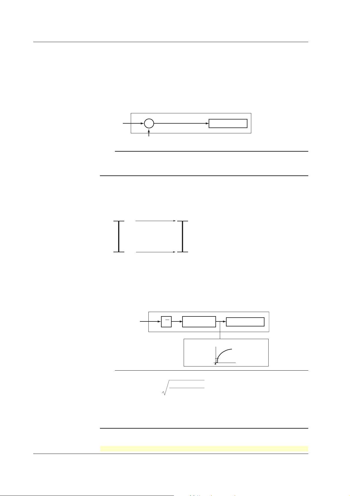
• Delta Computation
The value obtained by subtracting the measured value of another channel (called the
reference channel
) from the input value of the channel set to delta computation is used
as the measured value of that channel. The reference channel must be assigned to a
channel whose channel number is less than that of the channel on which delta
computation is specified. The channel on which delta computation is specified is
automatically set to the same range type as the reference channel.
Channel set to delta computation
Input
value
–
Measured value on the reference channel
Measured value
Note
A channel whose input type is set to DC voltage, TC, or RTD can be designated as a
reference channel. However, channels set to scaling or square root computation cannot be
designated.
• Scaling
The input values are scaled to values in the appropriate unit to be used as measured
values.
Measured valueInput value
10 V
0 V −100.0°C
• Square Root Computation
When the input type is DC voltage, the square root of the input value is calculated, the
result is scaled to a value in the appropriate unit, and used as the measured value of
the channel. Also, the low-cut function (input less than a given measured value is
fixed to 0% (scale left value)) can be used.
300.0°C
1-2
Channel set to square root computation
Input value
√
Scaling
Measured value
Low-cut value
Measured value
Result of square
root computation
Input value
Note
The square root computation on the recorder uses the following formula.
min
V - V
F = ( F - F )
x
max
min min
where V
min
(leftmost value of span) < V
F
min
(leftmost value of scale after scaling) < F
scaling)
Vx is the input voltage and Fx is the scaled value
x
max min
V - V
<Related Topics> Setting the input range: Section 5.1
For the procedure to set the functions, see section 1.6, “Function Setup Guide.”
+ F
max
(rightmost value of span)
max
(rightmost value of scale after
IM 04P03B01-01E
Page 9
1.1 Measuring Input Section
• Bias
A given value (bias value) is added to the input value and used as the measured
value of that channel.
Biased channel
Input value
+
Bias value
Measured value
<Related Topics> Setting the bias: Sections 4.15 and 3.10
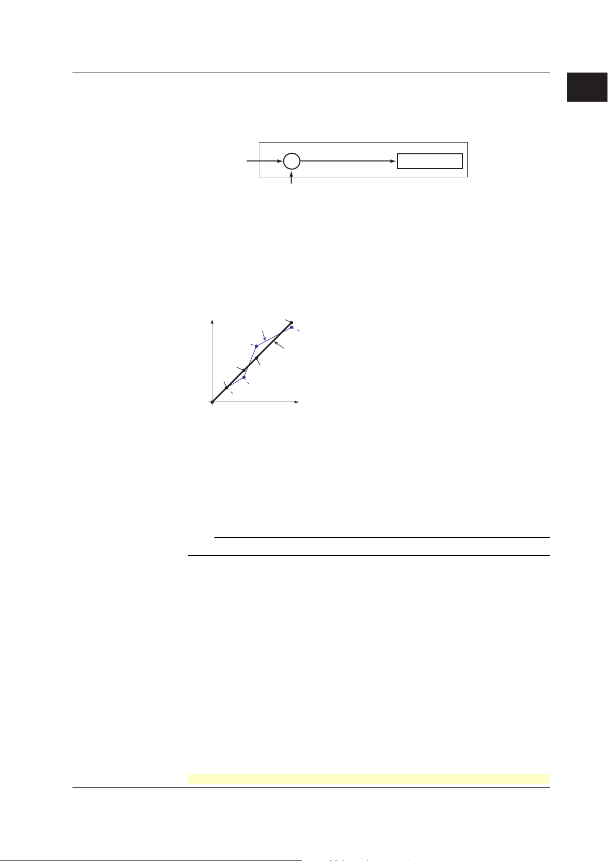
• Calibration Correction (/CC1 Option)
Corrects the measured value of each channel using segment linearizer approximation
and makes the resultant value the measured value of the channel. You can set
arbitrary correction values for 2 to 16 points of arbitrary measured values. Linear
approximation is used between two segment points. Correction values can be
assigned using revise values or absolute values.
Scale value
Measured value
B3
B2
B1
A2
A1
A4
A3
B4
B5
A5
Correction
value
Calibration point
Correction using
revise values
Measured value = A
Correction value = B – A
A1 to A5: Measured value (measured value before correction)
B1 to B5: Correction value (measured value after correction)
Correction using
absolute values
Measured value = A
Correction value = B
<Related Topics> Setting the calibration correction function: Sections 4.15, 4.22, and
3.11
1
Functional Explanation and Setup Guide
Burnout Detection of Thermocouples
This function makes the recording go off the scale to the right or left when the
thermocouple burns out while measuring temperature with a thermocouple. This function
can also be used on 1-5V. The burnout detection function can be set for each channel.
By default, this function is disabled.
Note
For 1-5V, a burnout occurs when the input value is less than or equal to 0.2 V.
<Related Topics> Setting the burnout detection function: Section 4.3
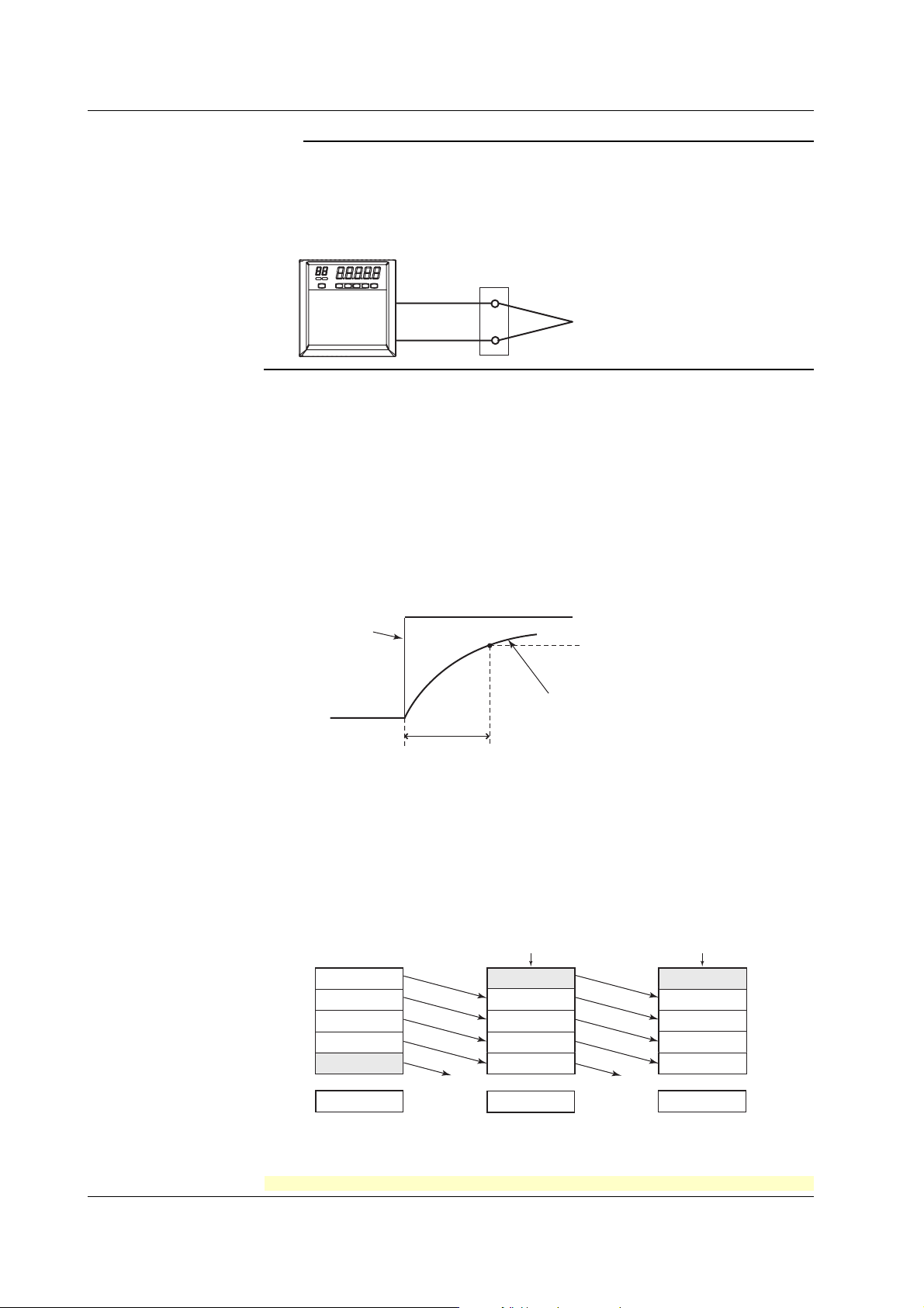
Reference Junction Compensation of Thermocouple Input
When measuring the temperature using a thermocouple, the reference junction
compensation on the recorder can be used. When using external reference junction
compensation, you can set the reference voltage. The reference junction compensation
can be set for each channel.
By default, the recorder is configured to use the internal reference junction compensation
function.
IM 04P03B01-01E
For the procedure to set the functions, see section 1.6, “Function Setup Guide.”
1-3
Page 10
1.1 Measuring Input Section
Note
When using external reference junction compensation, set an appropriate reference junction
compensation voltage. For example, if the reference junction temperature of the external
reference compensation is T0 °C, set the reference compensation junction voltage to the
thermoelectromotive force of the 0°C reference of T0 °C.
Example when using external reference junction compensation
Recorder
<Related Topics> Setting the reference junction compensation function: Section 4.4
Noise Elimination from Input Signals
Filter and Moving Average
This function used to suppress the effects of noise that is riding on the signal. The pen
model and dot model are equipped with a filter function and a moving average function,
respectively. The function can be set for each measurement channel. However, it does
not operate on channels set to ON/OFF input.
• Filter (Pen Model)
The filter is a low-pass filter. The time constant can be set to 2 s, 5 s, or 10 s.
Filter result (output for a step input)
Copper wire
External reference junction compensation
(Hold the contact point of the thermocouple
and copper wire at T
0
°C)
Thermocouple
Input signal
2, 5, 10 s (time constant, the time it takes
to reach 63.2% of the output value)
63.2% of the output value
Output response curve
(when using the filter)
• Moving Average (Dot Model)
The average value of the m most recent values acquired at the scan interval is used
as the measured value of the channel. The number of moving-averaged data points
(m) can be set in the range 2 to 16. The figure below shows an example indicating the
operation of the buffer for the moving average computation when the number of
moving averaged data points is set to 5.
Buffer data for the
n+2th sampling time
10.0 mV
15.0 mV
10.0 mV
5.0 mV
0.0 mV
Deleted
8.0 mV
Moving
average
Buffer data for the
nth sampling time
10.0 mV
1
5.0 mV
2
0.0 mV
3
–5.0 mV
4
–10.0 mV
5
0.0 mV
Buffer data for the
n+1th sampling time
Most recent data Most recent data
15.0 mV
10.0 mV
5.0 mV
0.0 mV
–5.0 mV
Deleted
5.0 mV
1-4
<Related Topics> Setting the filter: Sections 4.11 and 3.2
Setting the moving average: Sections 4.10 and 3.3
For the procedure to set the functions, see section 1.6, “Function Setup Guide.”
IM 04P03B01-01E
Page 11

1.1 Measuring Input Section
Integration Time of the A/D Converter
The recorder uses an A/D converter to convert the sampled analog signal to a digital
signal. By setting the integration time of the A/D converter to match the time period
corresponding to one cycle of the power supply or an integer multiple of one cycle, the
power supply frequency noise can be effectively suppressed.
The integration time of the A/D converter is selected according to the model from the
table below.
Model Integration Time of the A/D Converter
Pen model Select 16.7 ms (60 Hz), 20 ms (50 Hz), or Auto
Dot model Select 16.7 ms (60 Hz), 20 ms (50 Hz), 100 ms or Auto
• If Auto is selected, the recorder detects the power supply frequency and automatically
selects 16.7 ms or 20 ms.
• If Auto is specified when using the 24-VDC power supply on a recorder with the 24VDC/AC power supply (/P1 option), the integration time is fixed to 20 ms (50 Hz).
• Because 100 ms is an integer multiple of 16.7 ms and 20 ms, this setting can be used
to suppress the power frequency noise for either frequency, 50 Hz or 60 Hz.
• The scan interval on the dot model is 1 s when the integration time is set to 16.7 ms or
20 ms and 2.5 s when the integration time is set to 100 ms.
<Related Topics> Setting the A/D integration time: Section 4.2
1
Functional Explanation and Setup Guide
IM 04P03B01-01E
For the procedure to set the functions, see section 1.6, “Function Setup Guide.”
1-5
Page 12
1.2 Alarms
This function generates an alarm when the measured data meets a certain condition.
The alarm status is displayed on the screen while recording the alarm occurrence/
release on the chart paper.
Also, alarm output relays can be used to output contact signals when alarms occur (/A1,
/A2, and /A3 options).
Alarm Types
Number of Alarm Point Marks
Up to four alarms can be set for each channel.
Alarm Conditions
The following four conditions are available: The alphanumeric character or symbol inside
the parentheses is used on the recorder to denote each alarm.
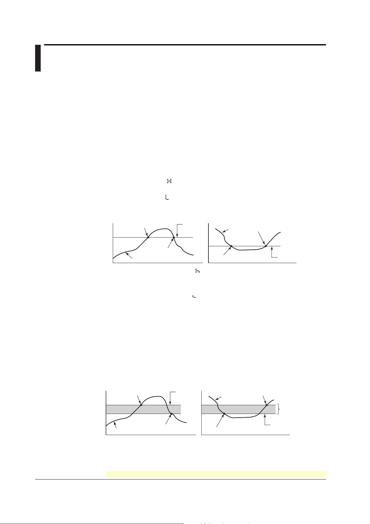
• High Limit Alarm (H/
• Low Limit Alarm (L/
)
An alarm occurs when the input value exceeds the alarm value.
)
An alarm occurs when the input value falls below the alarm value.
High limit alarm
Alarm occurrence
Measured value
Alarm
value
Alarm release
Low limit alarm
Measured
value
Alarm occurrence
Alarm release
Alarm value
• Difference High Limit Alarm (h/ )*
An alarm occurs when the difference in the input values of two channels is greater
than or equal to the specified value.
• Difference Low Limit Alarm (l/
)*
An alarm occurs when the difference in the input values of two channels is less than
or equal to the specified value.
* Can be specified on channels set to delta computation.
Alarm Hysteresis
Hysteresis can be specified to the values for activating and releasing the alarm. The
hysteresis applies only to high limit alarm (H) and low limit alarm (L). The hysteresis
width can be set in the range of 0.0% (OFF) to 1.0% of the recording span in 0.1 steps.
The setting applies to all high limit alarms and low limit alarms. By default, the hysteresis
width is set to 0.5%.
High limit alarm
Alarm occurrence
Measured value
Alarm
value
Alarm release
Low limit alarm
Measured
value
Alarm occurrence
Alarm release
Hysteresis
(1% or less)
Alarm value
1-6
<Related Topics> Setting alarms: Section 2.2
Setting the alarm hysteresis: Section 4.1
For the procedure to set the functions, see section 1.6, “Function Setup Guide.”
IM 04P03B01-01E
Page 13

1.2 Alarms
Alarm Indication
When an alarm occurs, the ALM indicator in the status display section illuminates, and
nd
the 2
digit of the LED shows the alarm status for each channel. When the alarm clears,
the indicator and the LED turn OFF.
Alarm Recording
The alarm occurrence/release can be recorded on the chart paper. See section 1.3.
Alarm Output Relay (/A1, /A2, and /A3 Options)
Contact signals can be generated from alarm output relays when alarms occur. The
number of output relays is 2 (/A1), 4 (/A2), or 6 (/A3). The alarm output relays are
denoted as I01 to I06 on the recorder.
The following functions can be assigned to the alarm output relay.
Diagnosis Output
The diagnosis output can be assigned to alarm output relay I01.
The relay is activated when there is an error in the plotter operation on the pen model,
when a burnout is detected, or when there is an error in the A/D converter. Output relay
I01 is normally energized and de-energizes when an error is detected (de-energized
operation).
Note
If diagnosis output is enabled, I01 becomes a relay dedicated to diagnosis output.
1
Functional Explanation and Setup Guide
<Related Topics> Setting the diagnosis output: Section 4.1
Energized/De-energized Operation of Alarm Output Relays
You can select whether the alarm output relay is energized or de-energized when an
alarm occurs. If de-energized is selected, the status of the alarm output relay when an
alarm occurs is the same as the status that results when the recorder is turned OFF
(including power failures). The setting applies to all alarm output relays.
The default setting is energized.
NO
Energize
De-energize
NO : Normally Opened, C : Common, NC : Normally Closed
CNC NOCNC NO C NC
NC
When power is
turned OFF
NO C NC NO C NCNO C
When an alarm
is not occurring
(During normal
operation)
When an alarm
is occurring
(During a
malfunction)
Note
If diagnosis output is enabled, I01 is fixed to de-energized operation.
IM 04P03B01-01E
<Related Topics> Setting the energized/de-energized operation of alarm output relays:
Section 4.1
Alarm Output Relay Operation
When the output destination of multiple alarms is assigned to a single alarm output relay,
the relay is activated when any of the assigned alarms is occurring (OR operation).
For the procedure to set the functions, see section 1.6, “Function Setup Guide.”
1-7
Page 14
1.3 Recording
The recorder is capable of recording the measured values with pens or dots (trend
recording) as well as various other types of information.
Trend Recording
The measured values are printed within a width of 100 mm.
Recording Method (Pen Model)
• The measured value is updated every scan interval and continuously recorded.
• The recording colors in order from channel 1 are red, green, blue, and violet.
Recording Method (Dot Model)
• The most recent measured value is recorded with a dot every dot printing interval.
The dot printing interval is in the range of 10 s to 90 s. There are two recording
methods from which you can select. One method automatically adjusts the dot
printing interval according to the chart speed so that the dots do not overlap. The
other method records at the fastest dot printing interval at all times.
• The recording colors in order from channel 1 are purple, red, green, blue, brown, and
black. The recording color of each channel can be changed among these six colors.
• For each channel, trend recording can be enabled or disabled.
<Related Topics> Setting the trend recording interval: Section 3.1
Changing the recording color: Section 4.5
Enabling/Disabling trend recording for each channel: Section 3.6
Chart Speed
On the pen model, the chart speed can be selected from 40 settings in the range of 10 to
12000 mm/h.
On the dot model, the chart speed can be selected from 28 settings in the range of 10 to
1500 mm/h.
The default setting is 20 mm/h.
<Related Topics> Setting the chart speed: Section 2.4
Zone Recording
A recording zone is assigned to each channel. This function is useful such when the
recording results overlap making them difficult to be viewed.
1-8
Zone 1 Zone 2 Zone 3 Zone 4
<Related Topics> Setting the zone recording: Section 3.4
For the procedure to set the functions, see section 1.6, “Function Setup Guide.”
IM 04P03B01-01E
Page 15
1.3 Recording
Partial Expanded Recording
This function expands a section of the recording range. By default, partial expanded
recording is disabled.
Compressed Expanded
<Related Topics> Setting the partial expanded recording: Sections 4.12 and 3.5
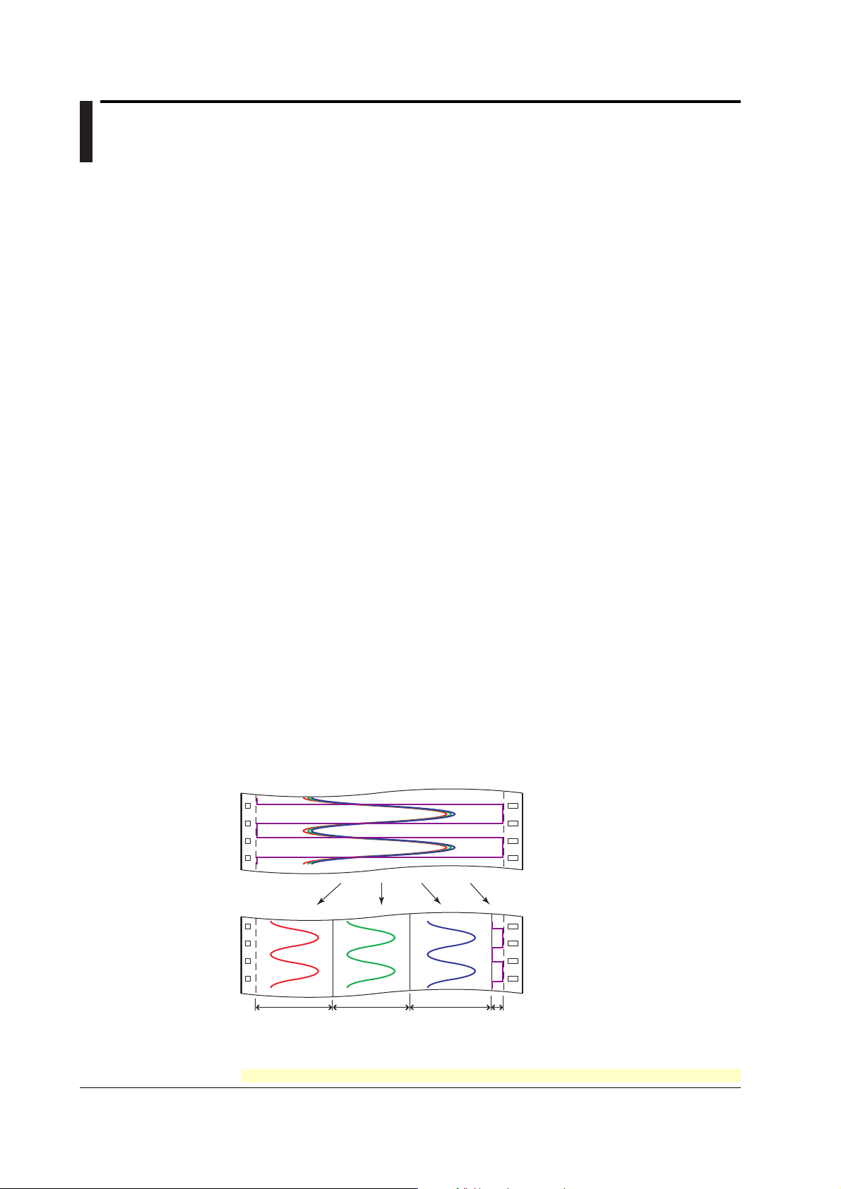
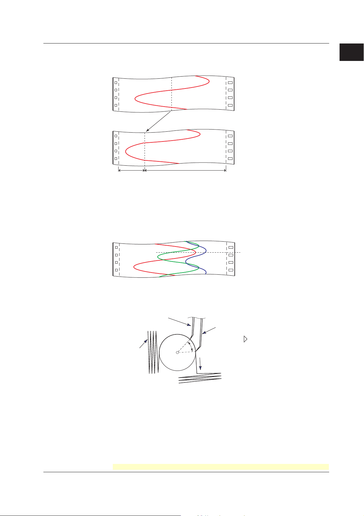
Pen Offset Compensation (Pen Model)
This function compensates for the pen offset (phase difference) along the time axis.
On 2-pen, 3-pen, and 4-pen recorders, there are offsets along the time axis (phase
difference) between the pens. This offset is corrected when pen offset compensation is
used.
1
Functional Explanation and Setup Guide
Same time
Below is an explanation for the 2-pen model.
The recording of these two pens are offset by an amount of phase P. If pen offset
compensation is enabled, the measured values of pen 1 are stored in the memory, and
recorded when the chart paper is fed by an amount corresponding to P.
Reference pen (pen 2)
Pen 1
Recorder front panel
Chart paper
P
Chart feeding direction
By default, this function is disabled.
<Related Topics> Setting the pen offset compensation: Section 4.6
IM 04P03B01-01E
For the procedure to set the functions, see section 1.6, “Function Setup Guide.”
1-9
Page 16
1.3 Recording
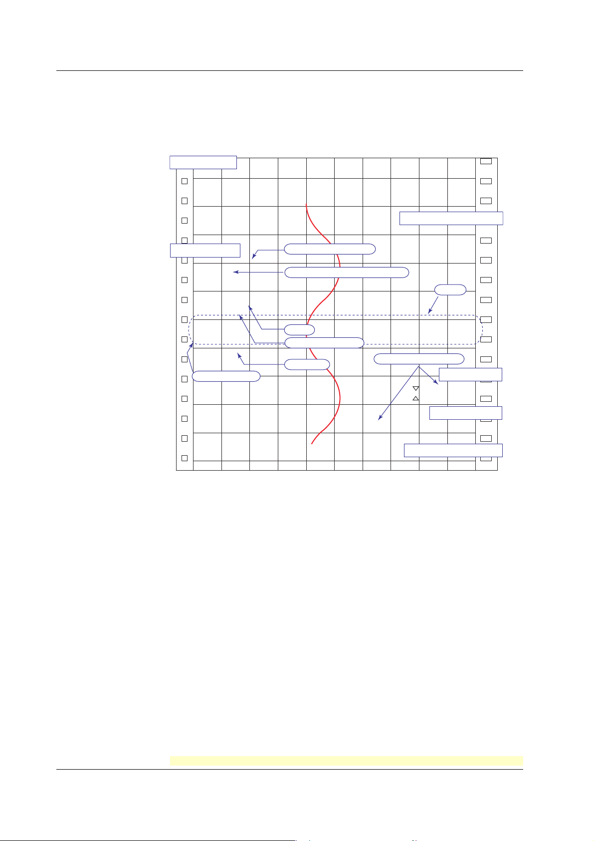
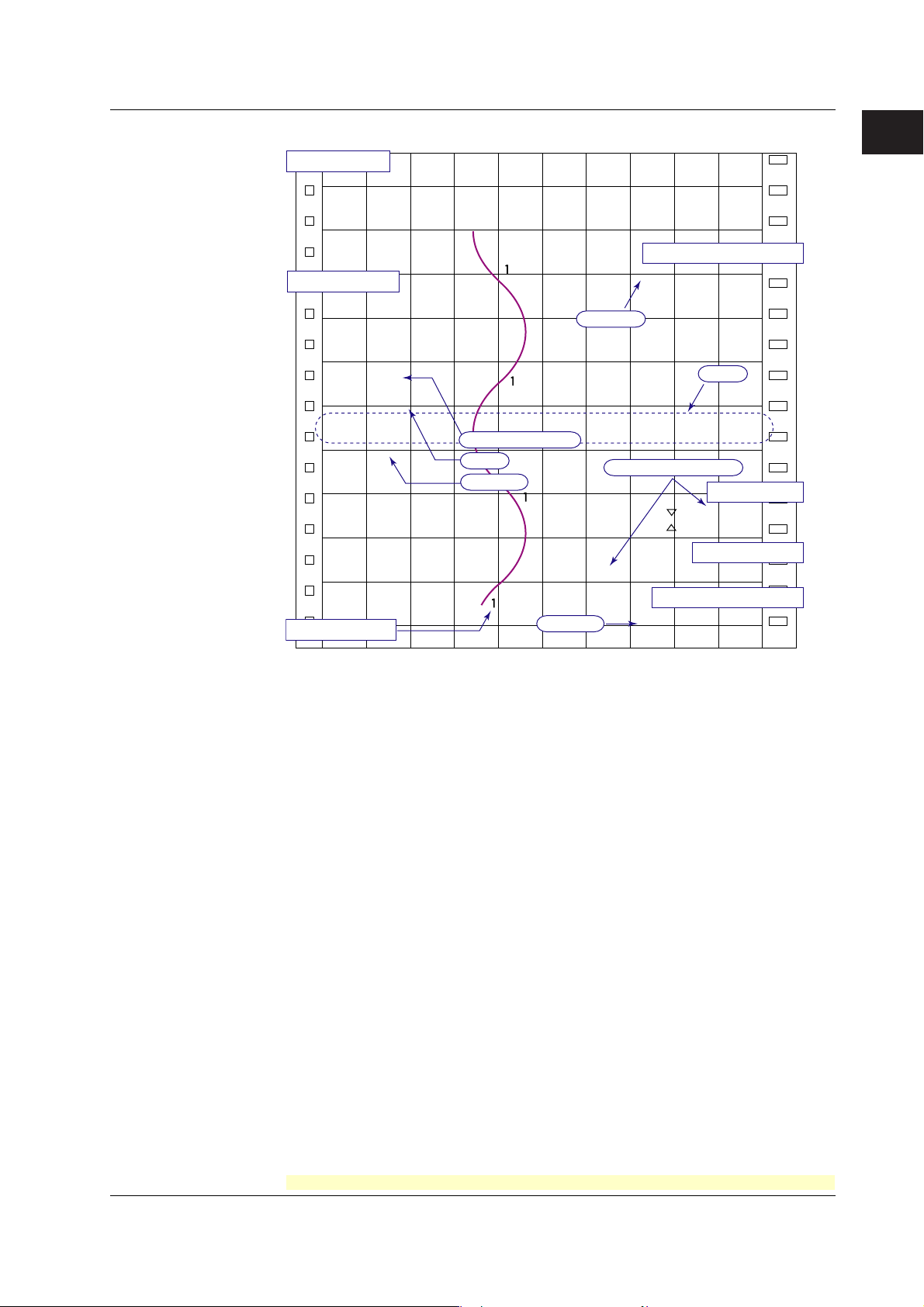
Printout
The figure below is used to explain the printout contents. The actual printout and font are
different from those illustrated in the figure. The printout positions are also slightly
different.
Printout Example on the Pen Model
Manual printout
Jan.31.05 15:00
1 223.5mg/cm
3
2 437.2µS/cm
3 H 591.6˚C 4d −0.222V
New chart speed printout
50mm/h 14:55
Periodic printout
Time tick cancel mark
Jan.31.05!
13:50*
1 218.7mg/cm
2 390.6µS/cm
Pen offset compensation mark
3
Scale
3 H 598.4˚C
4 d −0.222V
0.0 500.0
1CH mg/cm
RED
50mm/h_
Recording color
Alarm
Delta computation
Time tick
Buffer overflow mark
3
Alarm printout
1H3*10:09
1H3 10:05
Message printout
09:52*START#205 ABCDEF
Recording start printout
08:00 25mm/h
Time tick
The time ticks are marks that indicate the positions of the date/time on the chart paper.
Time tick cancel mark
An exclamation point (!) is printed when the periodic printout time tick was not printed at the
correct position.
Channel number or tag printout
Channel numbers or tags can be printed.
1-10
<Related Topics>
Switching between channel number printout and tag printout: Section 4.7
Setting the periodic printout
Turning printout ON/OFF
printout for periodic printout, and recording color printout for periodic printout)
(interval, reference time, and periodic printout ON/OFF): Section 4.8
(alarm printout, recording start printout, new chart speed printout, scale
: Section 4.7
Setting the time format (alarm printout, message printout, recording start printout, and new chart
speed printout): Section 4.16
Turning periodic printout ON/OFF for each channel: Section 3.6
Setting the message string: Section 3.8
Executing manual printouts, executing message printouts, clearing the alarm printout
buffer, and printing out settings: see the
Operation Guide
)
For the procedure to set the functions, see section 1.6, “Function Setup Guide.”
IM 04P03B01-01E
Page 17
1.3 Recording
Printout Example on the Dot Model
Manual printout
Jan.31.05 16:00
1 223.5mg/cm
3
2 437.2µS/cm
3 H 591.6˚C 4d −0.222V
5 −0.665V 6 L −0.448V
New chart speed printout
Periodic printout
_50mm/h 14:55
Jan.31.05
13:50
1 218.7mg/cm
3
Time tick
2 390.6µS/cm
3 H 598.4˚C
4 d −0.222V
5 −0.995V
6 L −0.448V
0.0 500.0
1CH mg/cm
50mm/h_
Delta computation
Alarm
Time tick
Buffer overflow mark
09:52*START#205 ABCDEF
1
Functional Explanation and Setup Guide
Scale
3
Alarm printout
1H3*10:09
1H3 10:05
Message printout
Recording start printout
Channel printout
Channel Printout (Dot Model Only)
Prints the channel No. or tag by the trend recording. The channel No. or tag is printed every
approximately 25 mm on the chart paper. The channel printout can be enabled or disabled. By
default, the channel printout is enabled.
Time tick
_08:00 25mm/h
<Related Topics>
Switching between channel number printout and tag printout: Section 4.7
Setting the periodic printout (interval, reference time, and periodic printout ON/OFF): Section 4.8
Turning printout ON/OFF
speed printout, and scale printout for periodic printout): Section 4.7
(channel printout, alarm printout, recording start printout, new chart
Setting the time format (alarm printout, message printout, recording start printout, and new chart
speed printout): Section 4.16
Turning recording and printout ON/OFF for each channel (trend recording and periodic
printout): Section 3.6
Setting the message string: Sections 3.8
Executing manual printouts, executing message printouts, clearing the alarm printout
buffer, and printing out settings: see the
Operation Guide
)
IM 04P03B01-01E
For the procedure to set the functions, see section 1.6, “Function Setup Guide.”
1-11
Page 18
1.3 Recording
Channel data
Recording color
Chart speed
Date
Time
Scale
Periodic Printout
Values such as the measured values are printed at a determined interval. The contents
of the printout vary between the pen model and dot model.
Printout cannot be performed at the following chart speeds.
Pen model: 1800 mm/h or higher; Dot model: 120 mm/h or higher
Channel No.
or tag
Measured
value
Unit
Time tick cancel mark
Offset compensation mark
Mar.31.2006!
15:50*
TAG-001 1.000V
2 -1.000V
3 H-2.1050UNIT03
4 d 2.000V
0.000 2.000
TAG-001 V
RED
50mm/h_
Time tick
The font used in the figure differs from that of the actual printout. The printout positions may
also differ from those of the actual printout.
Prints the letter “d” for channels set to
delta computation.
Alarm
• Printout Contents
• Date/Time: The date/time when the periodic printout was executed.
• Time ticks: Marks that indicate the first pen position of the date/time on the
chart paper. If the time tick is not printed in the correct position, the
pen model prints a time tick cancel mark (!), and the dot model does
not print the time tick.
• Offset compensation mark: When pen offset is being executed on the pen model,
asterisks (∗) are printed.
• Channel data: Prints the channel numbers or tags, measured values
(instantaneous values), and units.
• Alarm status: Prints the alarm that is occurring. Prints the letter “d” on channels
set to delta computation. If multiple alarms are occurring, the alarm
with the highest precedence is printed.
Alarm printout precedence: (Higher) H, L, h, and l (lower)
• Scale: Prints the leftmost and rightmost values of the recording span and
the channel number or tag for channels that have scale printout
specified. The scale is printed for one channel at each periodic
printout. The channel whose scale is printed changes in ascending
order. The scale of channels that are being zone recorded is printed
within the recording range of the zone for 40 mm or greater.
• Recording color (pen model): Prints the recording colors of channels that have
scale printout and recording color printout specified.
• Chart speed: The chart speed can be printed.
• For the measured values and alarm status, you can select whether to print them for
each channel. For the scale and recording color (pen model), you can select
whether to print them.
1-12
• Interval (for details, see appendix 1)
The printout interval can be set by specifying the value or set automatically in sync
with the chart speed.
• Turning ON/OFF the Periodic Printout
Periodic printout can be turn ON/OFF. By default, periodic printout is enabled with the
interval synchronized to the chart speed.
For the procedure to set the functions, see section 1.6, “Function Setup Guide.”
IM 04P03B01-01E
Page 19

1.3 Recording
Alarm Printout
Alarm information is printed when an alarm occurs or releases.
Printout cannot be performed at the following chart speeds.
Pen model: 1800 mm/h or higher; Dot model: 120 mm/h or higher
Time of alarm occurrence/release
Indicates that there are alarms that are not
printed because the alarm printout buffer is full.
Level number
Alarm type (H: high limit, L: low limit, h: difference high limit,
and l: difference low limit)
Channel No. or tag
: Alarm occurrence, : Alarm release
• The print condition can be set to (1) print when alarms occur and release, (2) print
only when alarms occur, or (3) do not print.
• Alarms that occur while an alarm printout is in progress are temporarily saved to the
buffer memory in a printout-wait condition. Alarms are cleared from the buffer memory
when they are printed.
• The number alarms that can be stored in the buffer is 8 and 12 on the pen model and
dot model, respectively. Alarms that occur while the buffer is full are not printed. A
buffer overflow mark is printed when there are alarms that cannot be printed because
the buffer is full.
• The time printout format can be selected.
1
Functional Explanation and Setup Guide
Manual Printout
Measured values and alarm status can be printed manually using the keys. When
manual printout is executed, trend recording stops and restarts when manual printout is
complete.
<For the operation procedure, see the
Operation Guide
.>
Message Printout
Printout cannot be performed at the following chart speeds.
Pen model: 1800 mm/h or higher; Dot model: 120 mm/h or higher
Preset messages can be printed on the chart paper using the keys. Five messages,
each within 16 characters, can be registered in advance.
• If message printout is executed while another message is being printed, the most
recent message is temporarily stored to the buffer memory in a printout-wait condition.
Messages are cleared from the buffer memory when they are printed.
• The number of messages that can be stored in the buffer is 5. If message printout is
executed when the buffer is full, the message is not printed. A buffer overflow mark is
printed when there are messages that cannot be printed because the buffer is full.
• The time printout format can be selected.
New Chart Speed Printout
Printout cannot be performed at the following chart speeds.
Pen model: 1800 mm/h or higher; Dot model: 120 mm/h or higher
• When the chart speed is changed, the time tick (dot model), the date/time of change,
and the new chart speed are printed. An asterisk (∗) shows there are messages that
cannot be printed.
• The time printout format can be selected.
IM 04P03B01-01E
For the procedure to set the functions, see section 1.6, “Function Setup Guide.”
1-13
Page 20
1.3 Recording
Recording Start Printout
Printout cannot be performed at the following chart speeds.
Pen model: 1800 mm/h or higher; Dot model: 120 mm/h or higher
When recording is started, the time tick (dot model), the time, and the chart speed can
be printed. An asterisk (∗) shows there are messages that cannot be printed.
• The recording start printout can be enabled or disabled. By default, the recording start
printout is disabled.
• The time printout format can be selected.
Printout/Display Format of the Date.
The printout/display format of the date can be selected from the list below.
Selectable Type Printout Format Display Format Notes
Settings Example Example
Year/Month/Day 2006/03/31 06 03 31 Default value
Month/Day/Year 03/31/2006 03 31 06
Day/Month/Year 31/03/2006 31 03 06
Day.Month.Year 31.03.2006 31 03 06
Month.Day.Year Mar.31.2006 03 31 06
*1 These do not apply for the date printout format for message printouts that include measured
values (/BT1 option). Specify that in the message format.
Printout Format of the Time
The printout format of the time can be selected from the list below.
Selectable Type Printout Format Notes
Settings Example
Hour:Minute 10:00 Default value
Hour:Minute:Second 10:00:00
Month/Day Hour:Minute 03/31 10:00
Month/Day Hour:Minute:Second 03/31 10:00:00
Year/Month/Day Hour:Minute:Second 2006/03/31 10:00:00
*1: The year/month/day format varies depending on the printout/display format of the date.
*2: Can be set to the alarm printout, message printout, recording start printout, and new chart
speed printout.
*3 These do not apply for the date printout format for message printouts that include measured
values (/BT1 option). Specify that in the message format.
1-14
<Related Topics> Setting the printout/display format of the date: Section 4.14
Setting the printout format of the time: Section 4.16
For the procedure to set the functions, see section 1.6, “Function Setup Guide.”
IM 04P03B01-01E
Page 21
1.3 Recording
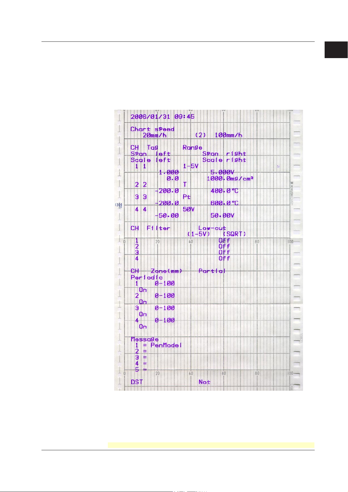
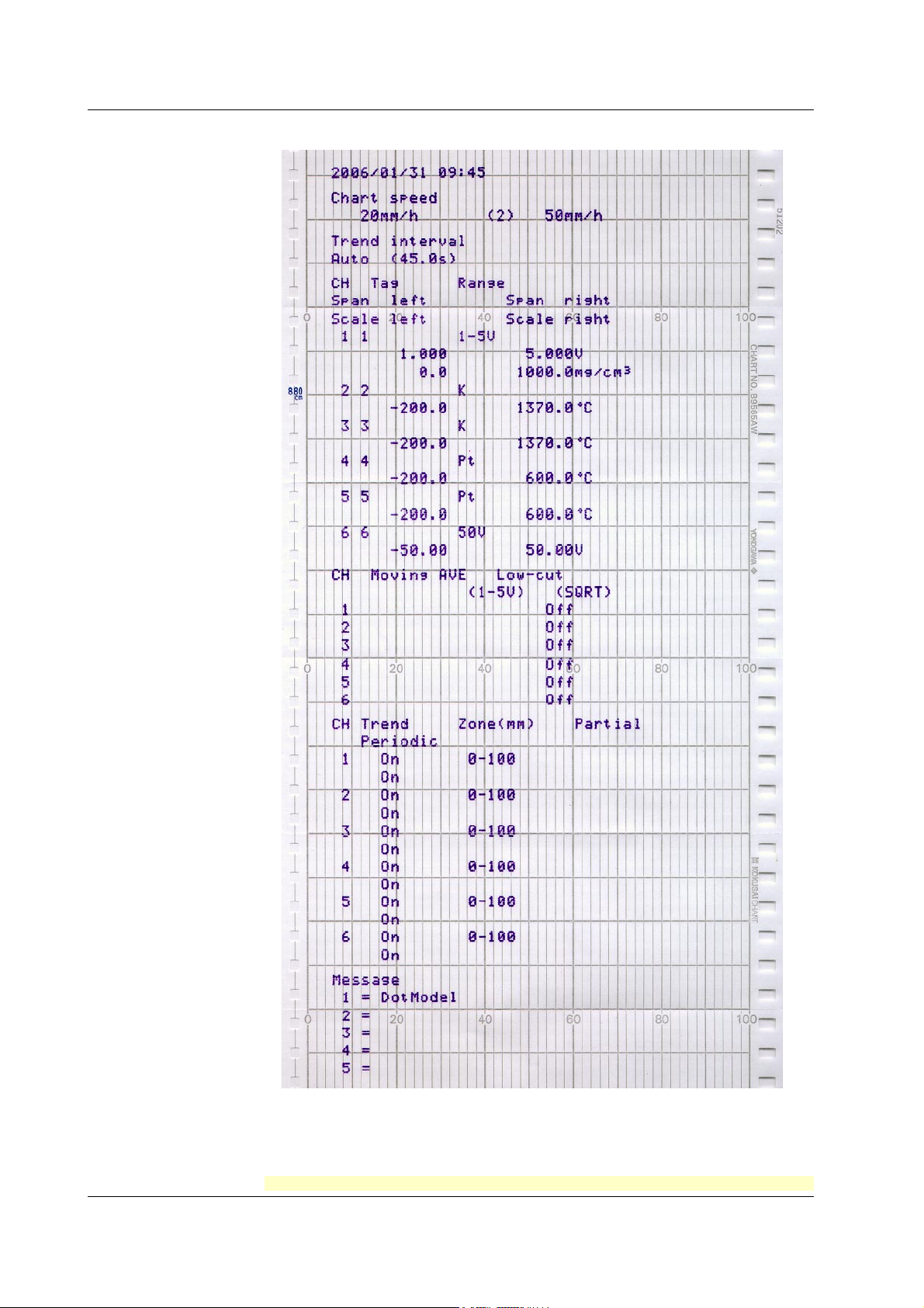
Setting Printout
List or setup list can be printed. When setting printout is executed, trend recording stops
and restarts when the printout is complete.
List printout contains Setting Mode settings such as the input range and alarm for each
channel.
Setup List contains Basic Setting Mode settings such as the alarm output relay operation
and printout method.
• Printout Example of List on the Pen Model
1
Functional Explanation and Setup Guide
IM 04P03B01-01E
The printout examples may appear differently from the actual printout as a result of functional
improvements made on the recorder after this manual was written.
For the procedure to set the functions, see section 1.6, “Function Setup Guide.”
1-15
Page 22
1.3 Recording
• Printout Example of List on the Dot Model
1-16
The printout examples may appear differently from the actual printout as a result of functional
improvements made on the recorder after this manual was written.
For the procedure to set the functions, see section 1.6, “Function Setup Guide.”
IM 04P03B01-01E
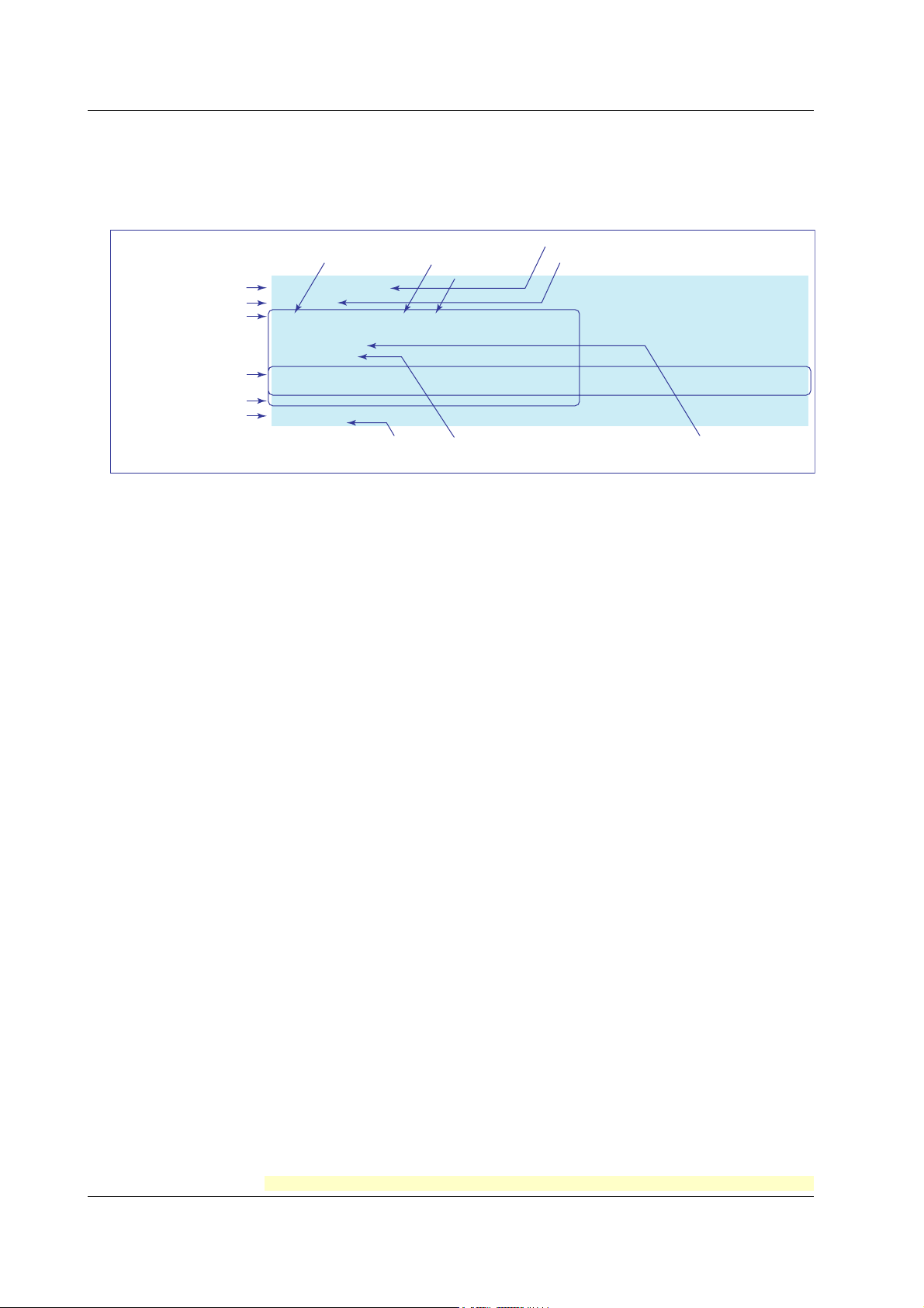
Page 23
1.3 Recording
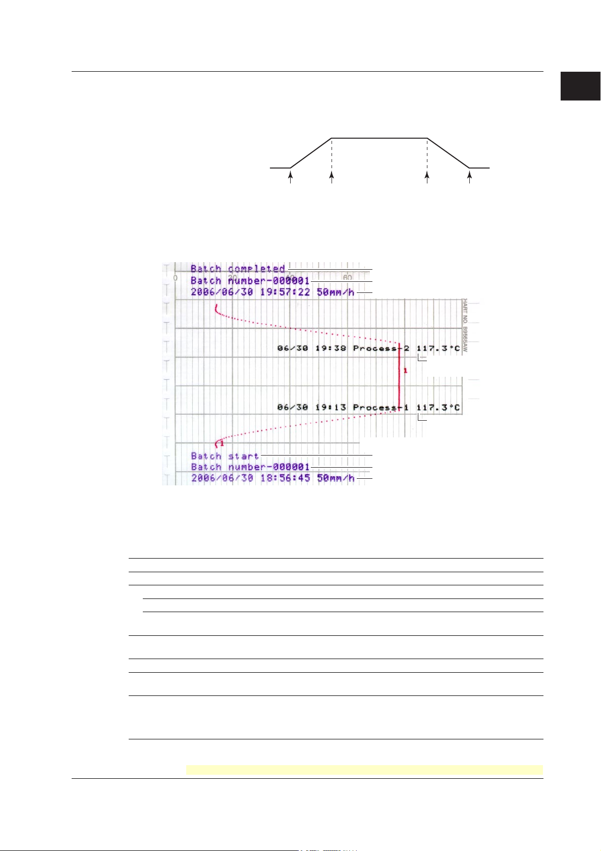
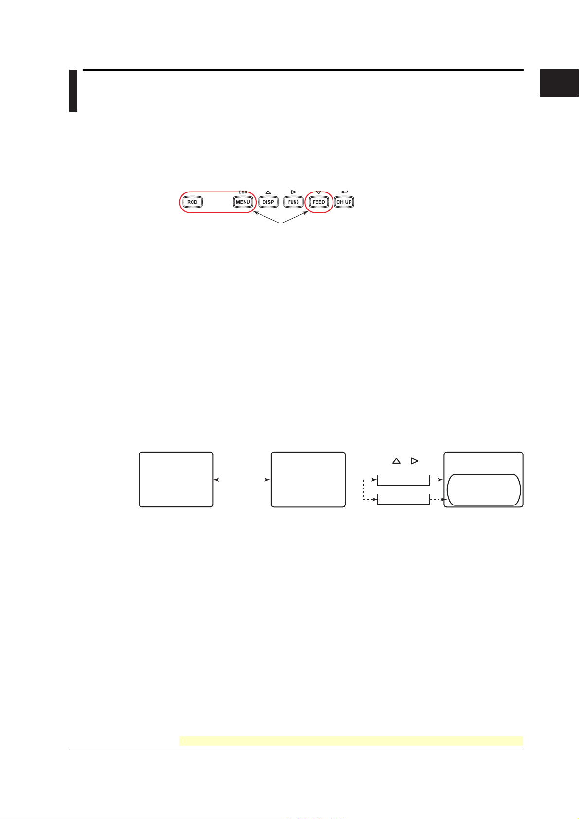
Header Printout (/BT1 Option)
When recording is started, the Start printout is performed, and recording starts. During
trend recording, you can print out messages (up to 5) that include measured values.
When recording is stopped, End printout is performed.
Operation
(Operation
instruction)
• Example Printout (Dot Model)
1. Chart paper feed
2. Start printout
3. Recording start
(Record start)
Message printout 1
including measured
values
(Message printout 1)
End printout
Comment
Batch name (batch number and lot number)
date/time, and chart speed
Message printout 2
including measured
values
(Message printout 2)
Message printout 2 including
measured values
1
Functional Explanation and Setup Guide
1. Recording stop
2. End printout
3. Chart paper feed
(Recording stop)
Message printout 1 including
measured values
Start printout
Comment
Batch name (batch number and lot number)
date/time, and chart speed
The printout examples may appear differently from the actual printout as a result of functional
improvements made on the recorder after this manual was written.
Start Printout and End printout
You can set “Start printout” and “Start printout 2” for the printout when recording starts.
Also, you can set “End printout” and “End printout 2” for the printout when recording stops.
Printout/Operation Description Notes
Comment Prints 32 characters x 5 lines or less.
Batch name
Batch number Prints up to 26 characters.
Lot number Prints a number from 4-digits or 6-digits. You can automatically increment
Date/time The date format prints out according to the date Date and time cannot be turned
printout/display format. On/Off independently.
Chart speed Prints the current chart paper feed speed.
Chart paper feed Feeds the chart paper 50 mm or less before Start printout. Steps of 1 mm
Feeds the chart paper 50 mm or less after End printout. Steps of 1 mm
Ejection of pen offset You can record the portion of the data that remains after When pen offset compensating
compensating data recording stops. Also, when recording the remaining is On (pen model).
portion of the data, you can change the chart speed to
450 mm/h (fixed).
by 1 when recording stops.
IM 04P03B01-01E
You can select whether to print out the batch name, date/time, and chart speed. By default, the printout is enabled.
For the procedure to set the functions, see section 1.6, “Function Setup Guide.”
1-17
Page 24

1.3 Recording
• Switching between Start Printout and Start printout 2, and between End printout
and End printout 2
With the remote control function (/R1 option), you can change the items that are
printed out.
For example, when a process ends successfully, End printout is performed and the lot
number is updated. If the process fails, you can have End printout 2 be carried out
and the lot number remain not updated.
Depending on the status of the “batch comment switching signal,” the following
switches occur when the “record start/stop signal” switches:
Batch Comment Switching Signal Status
Record start/Stop Signal Status Level: 0 (Open) Level: 1 (Closed)
Upon start Edge (rising) Start printout Start printout 2
Upon stop Edge (falling) End printout End printout 2
Remote Control Signal
Record start/stop
signal
Start Stop
Batch comment
switching signal
Start printout End printout
Concluded
successfully
Start Stop
Start printout End printout 2
Concluded
unsuccessfully
Message Printout Including Measured Values
Following the specified message format, the date/time, message strings of the standard
function (5 strings of up to 16 characters), and measured instantaneous values are
printed out together.
• Up to 5 messages of 35 characters can be entered.
• Messages are printed out in the order in which they are set.
• The specified number of characters specified for standard function messages is used,
then if a subsequent character string has been set, it is used next. Also, it can only be
used once for the message format.
Message Example
06/30 10:10 Process-1 134.8°C
Measured value on CH1 (no units)
Character string set for message 1
of the standard function
Date/time
<Related Topics> Setting start printout and stop printout: Sections 4.23 and 3.12
Assigning functions to the remote control input terminals: Section 4.18
Setting the message string: Section 3.8
Enabling the message format: Section 4.23
Regarding the message format: Section 3.13
1-18
For the procedure to set the functions, see section 1.6, “Function Setup Guide.”
IM 04P03B01-01E
Page 25
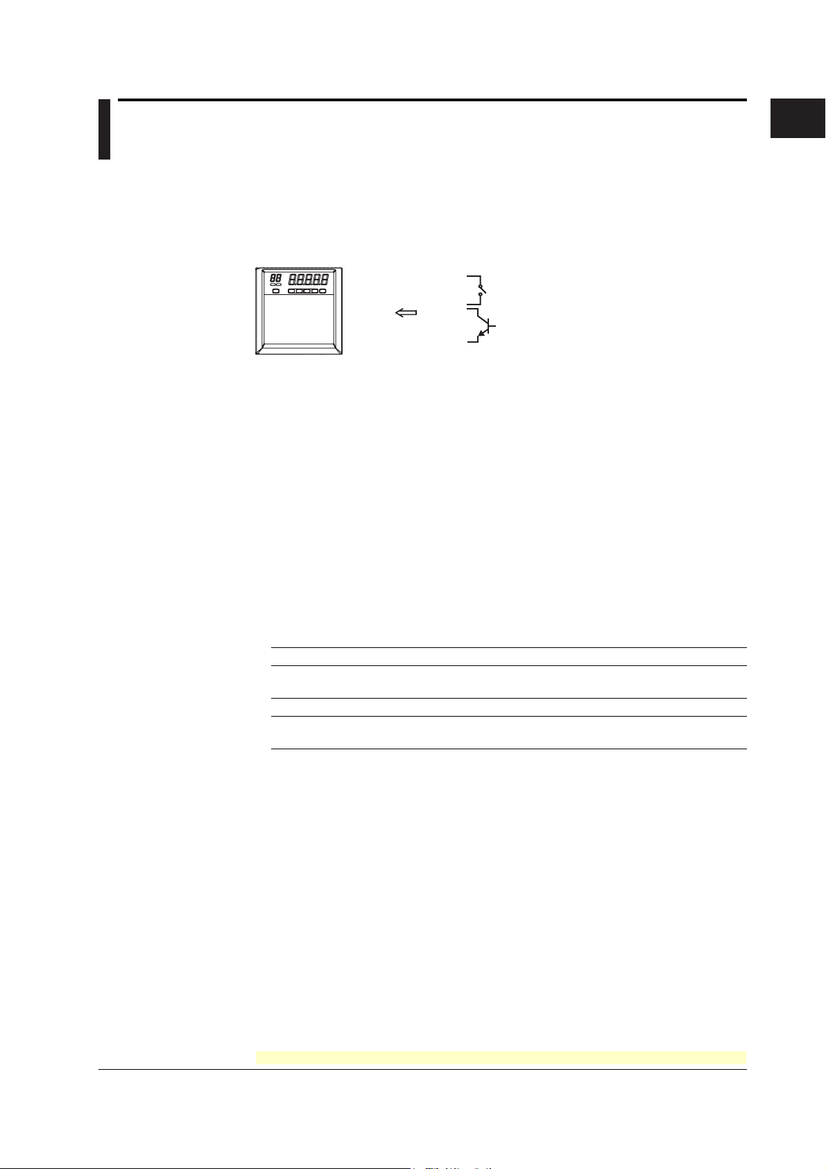
1.4 Remote Control Function (/R1 Option)
Specified operations can be carried out by applying remote signals (contact or open
collector signals) to the remote control input terminals.
There are five remote control input terminals. An action can be assigned to each
terminal.
Recorder
Contact
Open collector
Assignable Functions
• Recording start/stop
• Remote input signal: Rising edge signifies start; falling edge signifies stop
• Starts/stops recording.
• Applying a rising edge signal when recording is already in progress produces no
effect. Applying a falling edge signal when recording is stopped produces no effect.
• Chart Speed Switch
• Remote input signal: Level
• The chart paper is fed at the secondary chart speed while a level signal is applied
to the terminal. The secondary chart speed is set in advance.
1
Functional Explanation and Setup Guide
• Internal Clock Adjustment
• Remote input signal: Trigger
• The internal clock of the recorder is adjusted to the nearest hour depending on the
time when the remote signal is applied.
Time When Signal Is Input Adjustment
00 min 00 s to 01 min 59 s Truncates the minutes and seconds.
02 min 00 s to 57 min 59 s The time is not changed.
58 min 00 s to 59 min 59 s Rounds up the minutes and seconds.
• Message 1 Printout to Message 5 Printout
• Remote input signal: Trigger
• Manual Printout
• Remote input signal: Trigger
• Priority to Remote Recording (/BT1 Option)
• Remote input signal: Edge (rising/start or falling/stop)
• Starts/stops recording.
• When started with a remote signal (on a remote signal rise), stop per key operation
or communication is disabled.
Example: 10 hours 01 min 50 s becomes 10 hours 00 min 00 s.
Example: 10 hours 59 min 50 s becomes 11 hours 00 min 00 s.
IM 04P03B01-01E
For the procedure to set the functions, see section 1.6, “Function Setup Guide.”
1-19
Page 26
1.4 Remote Control Function (/R1 Option)
• Switching Batch Comment (/BT1 Option)
• Remote input signal: Level
• Switches between Start printout and Start printout 2, and between End printout and
End printout 2 depending on the status of the batch comment switching signal
when recording is started/stopped remotely.
• When starting/stopping by key operation, performs Start printout and End printout.
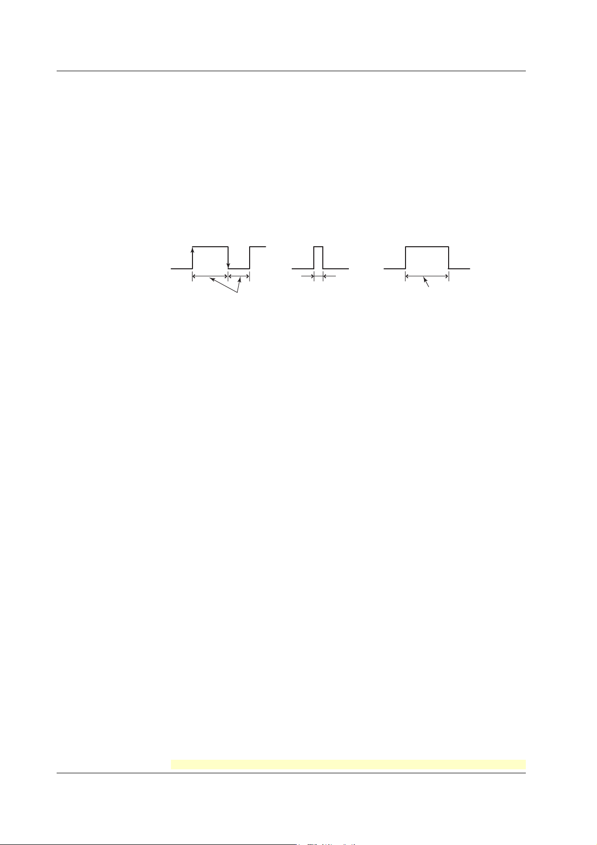
Remote Signal (Edge, Trigger, and Level)
The above actions are carried out on the rising or falling edge of the remote signal
(edge), the ON signal lasting at least 250 ms (trigger), or the ON/OFF signal (level).
Rising/Falling edge Trigger Level
Rising
Falling
For contact inputs, the remote signal rises when the contact switches from open to
closed and falls when the contact switches from closed to open. For open collector
signals, the remote signal rises when the collector signal (voltage level of the remote
control terminal) goes from high to low and falls when the collector signal goes low to
high.
250 ms or more
250 ms or more
Operates at the
secondary chart speed
<Related Topics> Assigning functions to the remote control input terminals: Section 4.18
Setting the secondary chart speed: Section 3.9
1-20
For the procedure to set the functions, see section 1.6, “Function Setup Guide.”
IM 04P03B01-01E
Page 27
1.5 Other Functions
Key Lock
Key lock is a function that prohibits key operations. When key lock is enabled, pressing
keys produces no effect. To release the key lock, a password is entered.
Key Lock Items
Each of the following keys can be included or excluded from the key lock function.
In the case of the FUNC key, each function of the FUNC key can be included or
excluded from the key lock function.
FUNC key functions: Manual printout, list printout, setup list printout, message printout,
<Related Topics> Setting the key lock function: Section 4.9
Using the key lock function: see the
Customize Menu
The menu can be customized to display only the menus that you use.
• Display only the items that you use on the FUNC key menu.
• Display only the items that you use on the Setting mode menu.
• Lock Basic Setting mode (use a password to enter the mode).
The pen position adjustment (pen model) and dot printing position adjustment (dot
model) can be set so that they can be used without the password.
Keys that can be locked
printout buffer clear, pen exchange (pen model), and ribbon
cassette exchange (dot model)
Operation Guide
)
1
Functional Explanation and Setup Guide
Font
Operation mode
Displays only the
FUNC key menu
items to be used
<Related Topics> Setting the FUNC key menu: Section 4.19
The characters used in the printout can be set to English, Japanese, German, or French.
The characters that are available vary depending on the selected font.
English: Alphabet, numbers, and symbols
Japanese: Alphabet, numbers, Katakana, and symbols
German: Alphabet (German), numbers, and symbols
French: Alphabet (French), numbers, and symbols
<Related Topics> Changing the language: Section 4.13
Hold down
MENU for 3 s
Setting the Setting mode menu: Section 4.20
Enabling/Disabling the customized menu: Section 4.21
Setting mode
Displays only the
setup menu items
to be used
Hold down +
for 3 s
Password
No password
Basic Setting mode
Pen and dot
printing position
adjustment
IM 04P03B01-01E
For the procedure to set the functions, see section 1.6, “Function Setup Guide.”
1-21
Page 28

1.5 Other Functions
DST
Temperature Unit
If the recorder is used in a region that has DST, time can be switched automatically
between DST and standard time by setting the date/time when switching from the
standard time to DST and the date/time when switching back from DST to standard time.
When switching from standard time to DST, the clock is set ahead by 1 hour. When
switching back from DST to standard time, the clock is set back by 1 hour.
<Related Topics> Using the DST: Section 3.14
The temperature unit can be set to Celsius or Fahrenheit. The setting applies to all
channels.
<Related Topics> Changing the temperature unit: Section 4.24
1-22
For the procedure to set the functions, see section 1.6, “Function Setup Guide.”
IM 04P03B01-01E
Page 29

1.6 Function Setup Guide
This section explains the settings necessary to use various functions of the recorder.
Read the section corresponding to the function you wish to use.
Note
This section contains all the settings related to each item. If the desired setting is the same as
the default value, you do not have to set it.
1
Functional Explanation and Setup Guide
Item Description Reference
Date/Time setting Use CLOCK in Setting mode 2.5
DST Sets the date/time for switching between DST and standard time using 3.14
AUX > DST in Setting mode.
Setting initialization Use INIT in Basic Setting mode to initialize the settings of Setting mode 4.17
and Basic Setting mode to their default values.
Measuring input functions
Item Description Reference
Range and span of the TC, RTD, or DC voltage
Use RANGE in Setting mode. 2.1
1-5V • Range, span, and scale 2.1
Use RANGE in Setting mode.
• Unit 2.3
Use UNIT in setting mode to set the unit after scaling.
• Low-cut 4.15
Use PERS. > 1-5V low-cut in Basic Setting mode and select Use or Not.
If Use is selected, turn ON/OFF the low-cut function using RANGE in Setting 2.1
mode.
If Not is selected, the Low-cut item does not appear in the RANGE setting.
Scaling • Range, span, and scale 2.1
Use RANGE in Setting mode.
• Unit 2.3
Use UNIT in setting mode to set the unit after scaling.
Square Root Computation • Range, span, and scale 2.1
Use RANGE in Setting mode.
• Unit 2.3
Use UNIT in setting mode to set the unit after scaling.
• Low-cut 4.15
Use PERS. > SQRT low-cut in Basic Setting mode and select Use or Not.
If Use is selected, set the low-cut value using RANGE in Setting mode. 2.1
If Not is selected, the Low-cut item does not appear in the RANGE setting.
Unused channels Use RANGE > SKIP in Setting mode to disabling the trend recording (dot model) 2.1
and periodic printout of the target channel.
Bias Use PERS. > BIAS in Basic Setting mode and select Use or Not. 4.15
If Use is selected, set the bias value that is added to the input using BIAS in 3.10
Setting mode. If Not is selected, the BIAS item does not appear.
Calibration Correction (/CC1 option)
Use PERS. > CALIB in Basic Setting mode and select Use or Not 4.15
If Use is selected,
• Use CALIB in Basic Setting mode to set the correction mode and the number 4.22
of calibration points.
• Use CALIB in Setting mode to set the measured value and correction value 3.11
for each channel.
If Not is selected, the CALIB item does not appear.
Burnout detection function (TC input and 1-5V input) 4.3
Use B_OUT in Basic Setting mode to set the burnout detection function for each
channel.
Section
Section
IM 04P03B01-01E
1-23
Page 30

1.6 Function Setup Guide
Item Description Reference
RJC of TC input Use RJC in Basic Setting mode to select whether to use the internal 4.4
RJC function or an external RJC function.
Filter (pen model) Use FILTR in Basic Setting mode and select Use or Not. 4.11
If Use is selected, set the filter time constant using AUX > FILTR in Setting mode. 3.2
If Not is selected, the AUX > FILTR item does not appear.
Moving average (dot model)
Use M_AVE in Basic Setting mode and select Use or Not. 4.10
If Use is selected, set the number of samples of moving average using AUX > 3.3
M_AVE in Setting mode.
If Not is selected, the AUX > M_AVE item does not appear.
Integration time of the A/D converter 4.2
Use INTG in Basic Setting mode to set the integration time of the A/D converter.
Temperature Unit Select the temperature unit using TEMP in Basic Setting mode. 4.24
Alarm functions
Item Description Reference
Alarms for each channel Use ALARM in Setting mode. 2.2
Set a hysteresis on the alarm occurrence/release value of high limit alarm and low limit alarm
Use ALARM > HYS in Basic Setting mode to set the hysteresis to be applied 4.1
to the high limit alarm and low limit alarm of measurement channels.
Diagnosis output Use ALARM > DIAG in Basic Setting mode to set the function. 4.1
Change the alarm output relay operation
If ALARM > RELAY in Basic Setting mode set to “DE_EN”, alarm output relay is 4.1
energized during normal operation and de-energized when an alarm occurs.
Section
Section
Recording functions
Item Description Reference
Section
Recording interval (dot model)
Change the recording color of measurement channels (dot model).
Turn trend recording ON/OFF (dot model)
Chart speed Use CHART in Setting mode to set the chart speed. 2.4
Record by setting recording zone
Partial expanded recording Use PART in Basic Setting mode and select Use or Not. 4.12
Record by compensating for the pen offset along the time axis (pen model)
Date format Use DATE in Basic Setting mode to set the printout/display format 4.14
Time format Use T_PRN in Basic Setting mode to set the printout format of the time. 4.16
Use AUX > TREND in Setting mode to set the recording interval to AUTO or FIX. 3.1
Use COLOR in Basic Setting mode to set the recording color of measurement 4.5
channels.
Use AUX > PRINT in Setting mode to turn ON/OFF the trend recording for each 3.6
measurement channel.
Use AUX > ZONE in Setting mode to set the recording zone for each channel. 3.4
If Use is selected, set the display mode using AUX > PART in Setting mode. 3.5
If Not is selected, the AUX > PART item does not appear.
Use POC in Setting mode to turn ON/OFF offset compensation. 4.6
of the date.
1-24
IM 04P03B01-01E
Page 31

1.6 Function Setup Guide
Item Description Reference
Periodic printout
Mar.31.2006!
15:50*
1 1.000V
2 -1.000V
0.000 2.000
1 V
RED
50mm/h_
• Enable/Disable the periodic printout 4.8
Use PER. in Basic Setting mode to turn ON/OFF the periodic printout.
• Printout interval 4.8
Use PER. in Basic Setting mode to set the periodic printout interval.
• Turn ON/OFF periodic printout for each channel 3.6
Use AUX > PRINT in Setting mode to turn ON/OFF the periodic printout for
each measurement channel.
• Scale printout and recording color printout (pen model) 4.7
Use PRINT > SCALE in Basic Setting mode to turn scale printout ON/OFF.
Use PRINT > PEN color in Basic Setting mode to turn pen color printout
ON/OFF (pen model).
Tag printout • Select channel printout or tag printout 4.7
Use PRINT > TAG.CH in Basic Setting mode to select whether to use channel
numbers or tags in printouts.
• Set the tag 3.7
Use AUX > TAG in Setting mode to set the tag name.
Alarm occurrence/release printout
• Turn printout ON/OFF 4.7
Use PRINT > ALARM in Basic Setting mode to select whether to print the alarm
occurrence and release, print only the alarm occurrence, or not print.
• Time printout format 4.16
Use T_PRN > ALARM in Basic Setting mode to set the time printout format
when printing alarm occurrence/release.
Message printout • Set the message string 3.8
Use AUX > MSG to set the message string to be printed.
• Time printout format 4.16
Use T_PRN > MSG in Basic Setting mode to set the time printout format.
• Execute the message printout Operation Guide
Use FUNC key > MSG in Operation mode to execute the message printout. Printing a Message
New chart speed printout • Turn printout ON/OFF 4.7
Use PRINT > SPEED in Basic Setting mode to set whether to print the new
chart speed when the chart speed is changed.
• Time printout format 4.16
Use T_PRN > SPEED in Basic Setting mode to set the time printout format.
Recording Start Printout • Turn printout ON/OFF 4.7
Use PRINT > RCD in Basic Setting mode to enable/disable the recording
start printout.
• Time printout format 4.16
Use T_PRN > RCD in Basic Setting mode to set the time printout format.
Setting Start printout/End printout (/BT1 option)
Use BATCH > DUAL (Dual comment) in Basic Setting mode, and select a LOT 4.23
from 4 or 6 digits.
Use BATCH > B.NUM in Setting mode to set the batch number. 3.12
Use BATCH > LOT in Setting mode to set the lot number. 3.12
Use BATCH > DETAI > START, END, STAT2, and END2 in Setting mode to set 3.12
the various comments, printout ON/OFF, and chart paper feed amount for each.
Also, in END and END2, enter the settings for lot number update and ejection of
pen offset compensating data (Pen model).
Channel number
or tag
Measured value
Scale
Recording color
(pen model)
Section
1
Functional Explanation and Setup Guide
IM 04P03B01-01E
1-25
Page 32

1.6 Function Setup Guide
Item Description Reference
Section
Switching between Start printout and Start printout 2, and between End printout and End printout 2 (/BT1, /R1 option)
• Switching settings
Assign DUAL (Batch comment switching) to the remote control input terminal. 4.18
Use BATCH > DUAL (Dual comment) in Basic Setting mode and select Use. 4.23
Set BATCH > DETAI > STAT2, and END2 in Setting mode. 3.12
• Executing the switch
The switch occurs according to the status of the DUAL (Batch comment 1.3
switching) signal when RCD or PR.RCD signal assigned to the remote control
input terminal rises or falls.
Printout of messages including measured values (/BT1 option)
• Setting message strings 3.8
Use AUX > MSG in Setting mode to enter the message to print out.
• Setting the message format 4.23
Use BATCH > MSG_F in Basic Setting mode and select Use.
Set the message format using the PC software (sold separately) or a
communication command.
• Executing the message printout
Execute the message printout by choosing FUNC key > MSG in Operation Guide
Operation mode. Printing a Message
Display functions
Item Description Reference
Section
Date format Same as the Date format in “Recording functions.” 4.14
Other functions
Item Description Reference
Section
Key lock • Target keys and password 4.9
Use LOCK in Basic Setting mode to set the keys to be key-locked and the
password.
• Enable the key lock Operation Guide
Use FUNC key > LOCK in Operation mode to turn key lock ON/OFF. Activating/Releasing
the Key Lock
Customize menu • FUNC key target menu selection 4.19
Use S.MENU > FUNC in Basic Setting mode to select the menus to be displayd.
• Setting mode target menu selection 4.20
Use S.MENU > SET in Basic Setting mode to select the menus to be displayd.
• Customize menu execution 4.21
Use CUST.M in Basic Setting mode to select whether to use the customized menu.
Font Use FONT in Basic Setting mode to set the characters used in the recording. 4.13
Remote control function • Assign functions to the remote control input terminals 4.18
(/R1 option) Use REM in Basic Setting mode to set the function to be assigned to the
remote control input terminal.
• Secondary chart speed 3.9
If “chart speed switching” is assigned, use AUX > SPD_2 in Setting mode to
set the secondary chart speed.
• Switching between Start printout and Start printout 2, and between End
printout and End printout 2 (/BT1 option)
If DUAL (Batch comment switching) is assigned, 4.23
Use BATCH > DUAL (Dual comment) in Basic Setting mode. Set BATCH > 3.12
DETAI > STAT2, and END2 in Setting mode.
1-26
IM 04P03B01-01E
Page 33

Chapter 2 Frequently Used Setup Operations (Setting Mode)
2.1 Setting the Input Range
Procedure
TC, RTD, and DC Voltage
Input range can be set for each measurement channel. Set unused channels to Skip.
If you change the input range, set the bias, alarm, partial expanded recording, and
calibration correction again.
1. Hold down the
key for 3 seconds to enter Setting mode.
MENU
2. Carry out the procedure shown in the figure below.
Press the or key to select the value.
For the procedure on how to enter values or characters, see page 19 in the
Operation Guide
.
To change the polarity, press the or key when the leftmost digit of the
value is blinking.
If you press the
key, the operation is cancelled, and the display returns to a
higher level menu.
Select “RANGE.”
(RANGE)
Select the channel number.
(CH1)
2
Frequently Used Setup Operations (Setting Mode)
Select the input type.
(TC)
Channel number
Select the range.
(R)
Set the left span value.
Span left
Set the right span value.
Span right
The settings are activated.
(OK)
3. Press the key to set other channels.
If you are done, press the key.
4. Hold down the
key for 3 seconds to return to Operation mode.
MENU
IM 04P03B01-01E
2-1
Page 34

2.1 Setting the Input Range
Description
• Selectable Range of Input Range, Span Left, and Span Right
The input range, span left, and span right can be set in the range shown below. Span
left and span right cannot be set to the same value.
DC voltage ( )
Range Type Selectable Span Range
20 mV( ) –20.00 to 20.00 mV
60 mV( ) –60.00 to 60.00 mV
200 mV( ) –200.0 to 200.0 mV
2 V( ) –2.000 to 2.000 V
6 V( ) –6.000 to 6.000 V
20 V( ) –20.00 to 20.00 V
50 V( ) –50.00 to 50.00 V
Thermocouple ( )
Range Type Selectable Span Range (°C) Selectable Span Range (°F)
R ( ) 0.0 to 1760.0°C 32 to 3200°F
S ( ) 0.0 to 1760.0°C 32 to 3200°F
B ( ) 0.0 to 1820.0°C 32 to 3308°F
K ( ) –200.0 to 1370.0°C –328 to 2498°F
E ( ) –200.0 to 800.0°C –328.0 to 1472.0°F
J ( ) –200.0 to 1100.0°C –328.0 to 2012.0°F
T ( ) –200.0 to 400.0°C –328.0 to 752.0°F
N ( ) 0.0 to 1300.0°C 32 to 2372°F
W ( ) 0.0 to 2315.0°C 32 to 4199°F
L ( ) –200.0 to 900.0°C –328.0 to 1652.0°F
U ( ) –200.0 to 400.0°C –328.0 to 752.0°F
WRe ( ) 0.0 to 2400.0°C 32 to 4352°F
RTD ( )
Range Type Selectable Span Range (°C) Selectable Span Range (°F)
PT (Pt100) ( ) –200.0 to 600.0°C –328.0 to 1112.0°F
JPT(JPt100) ( ) –200.0 to 550.0°C –328.0 to 1022.0°F
/N1 option /N3 option
Selectable
Settings
Cu1
Cu2
Cu3
Cu4
Cu5
Cu6
Cu25
Input Type
Cu10 (GE)
Cu10 (L&N)
Cu10 (WEED)
Cu10 (BAILEY)
Cu10: a = 0.00392 at 20°C
Cu10: a = 0.00393 at 20°C
Cu25*: a = 0.00425 at 0°C
Selectable Input Type Notes
Setting
PR PR40-20 Thermocouple
PLATI PLATINEL
NiMo NiNiMo
W/WRe W/WRe26
N2 Type N (AWG14)
Kp Kp vs Au7Fe
Pt4 Pt25 RTD
Pt3 Pt50
Ni1 Ni100 (SAMA)
Ni2 Ni100 (DIN)
Ni3 Ni120
J263 J263*B
Cu8 Cu53
Cu9
Cu100: a = 0.00425 at 0°C
2-2
IM 04P03B01-01E
Page 35

1-5V Input
(RANGE)
(CH1)
Channel number
(1-5V)
Span left
Span right
2.1 Setting the Input Range
Select “RANGE.”
Select the channel number.
Select “1-5V.”
Set the left span value.
Set the right span value.
Select the left scale value and the decimal place.
2
Frequently Used Setup Operations (Setting Mode)
Scale left
Decimal point
Select the right scale value.
Scale right
(When low-cut is enabled)
Select whether to use low-cut.
(ON)
Low-cut
The settings are activated.
(OK)
Description
• Span Left and Span Right
Selectable span left range: 0.8 to 1.2 V
Selectable span right range: 4.8 to 5.2 V
• Scale Left, Scale Right, and Decimal Place
Selectable range (mantissa): –19999 to 30000
Example: The value in the range of –100.00 to 350.00 cannot be specified. The
mantissa of scale right is 35000, which exceeds the upper limit to 30000.
Set in the range of –100.0 to 350.0.
Decimal place: XXXXX, XXXX.X, XXX.XX, XX.XXX, X.XXXX
To set the decimal place for the left scale setup item, press the
key to make
blink, then press the or key.
The decimal position is the position specified by scale left.
Make sure that left scale is less than scale right.
IM 04P03B01-01E
• Low-Cut
ON (
): Cuts values less than or equal to 0% of the recording span (sets
such values to 0% (scale left value)).
OFF (
): Does not apply the low-cut function.
<Related Topics> Setting the unit: Section 2.3
Enabling the low-cut function: Section 4.15
2-3
Page 36

2.1 Setting the Input Range
Linear Scaling
Select “RANGE.”
(RANGE)
Select the channel number.
(CH1)
Select “SCALE.”
(SCALE)
Channel number
Select the input type.
(VOLT)
Select the range.
(2V)
Set the left span value.
Span left
Set the right span value.
Span right
Select the left scale value and the decimal place.
Scale left
Decimal point
Select the right scale value.
Scale right
The settings are activated.
(OK)
Description
• Span Left and Span Right
Same as the selectable span range of the DC voltage, Thermocouple, and RTD
range.
• Scale Left, Scale Right, and Decimal Place
Selectable range (mantissa): –19999 to 30000
Example: The value in the range of –100.00 to 350.00 cannot be specified. The
mantissa of scale right is 35000, which exceeds the upper limit to 30000.
Set in the range of –100.0 to 350.0.
Decimal place: XXXXX, XXXX.X, XXX.XX, XX.XXX, X.XXXX
To set the decimal place for the left scale setup item, press the
key to make
blink, then press the or key.
The decimal position is the position specified by scale left.
2-4
<Related Topics> Setting the unit: Section 2.3
IM 04P03B01-01E
Page 37

Delta Computation
(RANGE)
(CH2)
(DELTA)
Channel number
(CH1)
Span left
Span right
(OK)
2.1 Setting the Input Range
Select “RANGE.”
Select the channel number.
Select “DELTA.”
Select the reference channel.
Set the left span value.
Set the right span value.
The settings are activated.
2
Frequently Used Setup Operations (Setting Mode)
Description
• Reference Channel
The reference channel must be a channel that is smaller in channel number than the
channel being set.
• Span Left and Span Right
The range type is the same as the reference channel. The span left and span right
can be set in the range shown below. Span left and span right cannot be set to the
same value.
Input Type Range Type Selectable Span Range (°C) Selectable Span Range (°F)
DC voltage 20 mV ( ) –20.00 to 20.00 mV
( ) 60 mV ( ) –60.00 to 60.00 mV
Thermocouple R ( ) –1760.0 to 1760.0°C –3168 to 3168°F
( )S () –1760.0 to 1760.0°C –3168 to 3168°F
RTD PT(Pt100) ( ) –800.0 to 800.0°C –1440.0 to 1440.0°F
( ) JPT(JPt100) ( ) –750.0 to 750.0°C –1350.0 to 1350.0°F
200 mV ( ) –200.0 to 200.0 mV
2 V ( ) –2.000 to 2.000 V
6 V ( ) –6.000 to 6.000 V
20 V ( ) –20.00 to 20.00 V
50 V ( ) –50.00 to 50.00 V
B ( ) –1820.0 to 1820.0°C –3276 to 3276°F
K ( ) –1570.0 to 1570.0°C –2826 to 2826°F
E ( ) –1000.0 to 1000.0°C –1800 to 1800°F
J ( ) –1300.0 to 1300.0°C –1999.9 to 2340.0°F
T ( ) –600.0 to 600.0°C –1080.0 to 1080.0°F
N ( ) –1300.0 to 1300.0°C –2340 to 2340°F
W ( ) –1999.9 to 2315.0°C –4167 to 4167°F
L ( ) –1100.0 to 1100.0°C –1980 to 1980°F
U ( ) –600.0 to 600.0°C –1080.0 to 1080.0°F
WRe ( ) –1999.9 to 2400.0°C –4320 to 4320°F
IM 04P03B01-01E
2-5
Page 38

2.1 Setting the Input Range
ON/OFF Input
Select “RANGE.”
(RANGE)
Select the channel number.
(CH1)
Select “DI.”
(DI)
Channel number
Select contact or level.
(CONT)
Set the left span value.
Span left
Set the right span value.
Span right
The settings are activated.
(OK)
Description
• Selectable Range of Input Range, Span Left, and Span Right
The input range, span left, and span right can be set in the range shown below. Span
left and span right cannot be set to the same value.
Range Type Selectable Span Values
Level ( ) 0: Less than 2.4 V, 1: 2.4 V or higher, within ±6 V
Contact ( ) 0: Open, 1: Closed
2-6
IM 04P03B01-01E
Page 39

Square Root Computation
(RANGE)
(CH1)
(SQRT)
Channel number
(2V)
Span left
Span right
2.1 Setting the Input Range
Select “RANGE.”
Select the channel number.
Select “SQRT.”
Select from the range types of DC voltage.
20 mV, 60 mV, 200 mV, 2 V, 6 V, 20 V, or 50 V
Set the left span value.
Set the right span value.
Select the left scale value and the decimal place.
2
Frequently Used Setup Operations (Setting Mode)
Scale left
Decimal point
Select the right scale value.
Scale right
(Displays the following when the low-cut
is enabled)
(ON)
Low-cut
Turn ON or OFF the low-cut function.
Set the low-cut point.
0.0 to 5.0% of the recording span, 0.1 steps.
The settings are activated.
(OK)
Description
• Input Type on Which Square Root Computation Can Be Performed
Square root computation can be performed when set to DC voltage input.
• Span Left and Span Right
Same as the selectable span range of the DC voltage range.
Make sure that span left is less than span right.
• Scale Left, Scale Right, and Decimal Place
Selectable range (mantissa): –19999 to 30000
Example: The value in the range of –100.00 to 350.00 cannot be specified. The
mantissa of scale right is 35000, which exceeds the upper limit to 30000.
Set in the range of –100.0 to 350.0.
Decimal place: XXXXX, XXXX.X, XXX.XX, XX.XXX, X.XXXX
To set the decimal place for the left scale setup item, press the
key to make
blink, then press the or key.
The decimal position is the position specified by scale left.
Make sure that scale left is less than scale right.
IM 04P03B01-01E
2-7
Page 40

2.1 Setting the Input Range
Skip (Unused Channels)
• Low-Cut and Low-Cut Point
If low-cut is set to ON, set the low-cut point.
Selectable range of the low-cut point: 0.0 to 5.0% of the recording span
Values below the low-cut point is set to 0% of the recording span (scale left value).
<Related Topics> Setting the unit: Section 2.3
Enabling the low-cut function: Section 4.15
Select “RANGE.”
(RANGE)
Select the channel number.
(CH1)
Select “SKIP.”
(SKIP)
Channel number
The settings are activated.
(OK)
Note
Do not use channels set to skip as a reference channel of delta computations.
2-8
IM 04P03B01-01E
Page 41

2.2 Setting the Alarm
Procedure
An alarm can be set for each channel.
If you change the input range, set the alarm again.
1. Hold down the
key for 3 seconds to enter Setting mode.
MENU
2. Carry out the procedure shown in the figure below.
Press the or key to select the value.
For the procedure on how to enter values or characters, see page 19 in the
Operation Guide
.
To change the polarity, press the or key when the leftmost digit of the
value is blinking.
If you press the
key, the operation is cancelled, and the display returns to a
higher level menu.
Select the “ALARM.”
(ALARM)
Select the channel number.
(CH1)
Select the level number between 1 and 4.
(L4)
Channel number
Select ON to set the alarm.
2
Frequently Used Setup Operations (Setting Mode)
(ON)
Level number
(Displays the following when the alarm
is ON)
(H)
Select the alarm type.
Set the value used to turn ON the alarm.
Select ON to set the alarm relay output.
This setting is valid only on models with
(ON)
Relay output
the /A1, /A2, or /A3 option.
(When the alarm output is ON)
Specify the alarm output relay number.
(I01)
The settings are activated.
(OK)
3. Press the key to set other channels.
If you are done, press the key.
4. Hold down the
key for 3 seconds to return to Operation mode.
MENU
IM 04P03B01-01E
2-9
Page 42
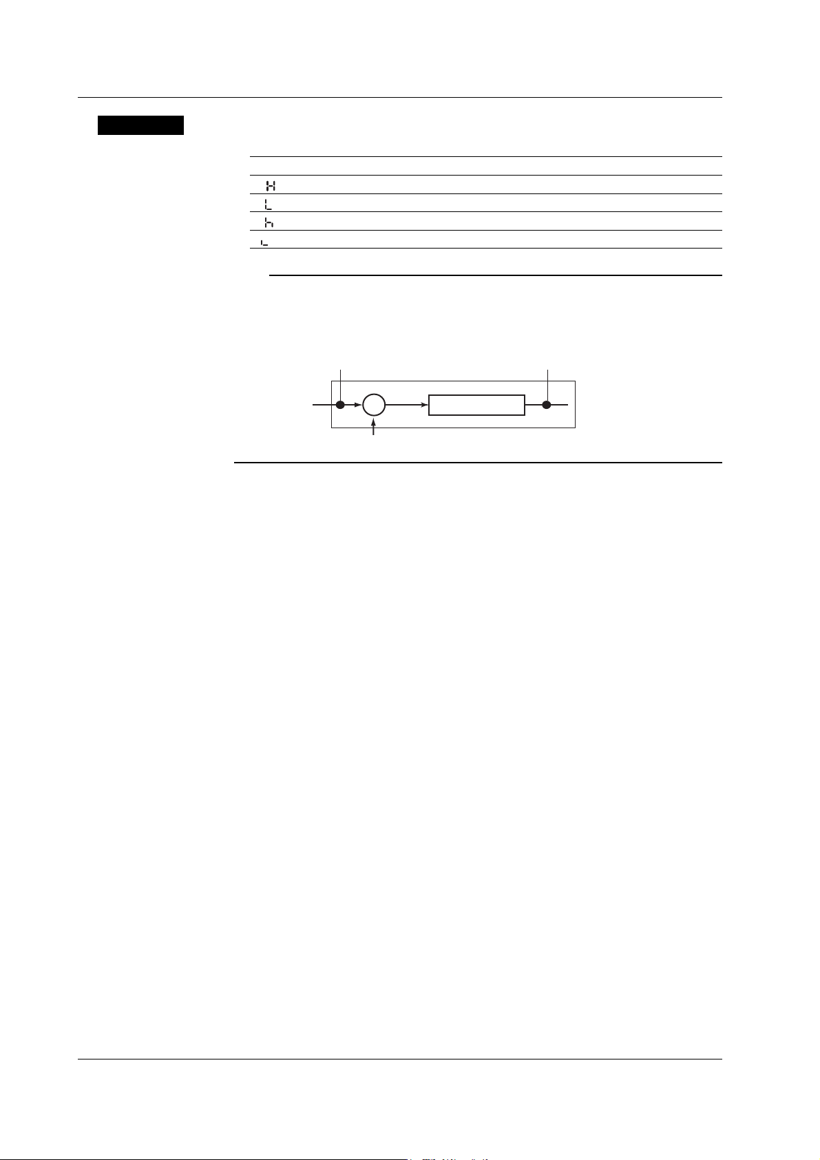
2.2 Setting the Alarm
Explanation
Alarm Type
Symbol Name Notes
H ( ) High limit alarm
L ( ) Low limit alarm
h ( ) Difference high limit alarm Can be specified on channels set to delta computation.
l ( ) Difference low limit alarm Can be specified on channels set to delta computation.
Note
On channels set to delta computation, alarms can be detected on the values illustrated in the
figure below.
Alarm on a channel set to delta computation
Alarm
H, L
Alarm
h, l
Input value
−
Measured value on the reference channel
Measured value
Alarm Value
• High Limit Alarm/Low Limit Alarm
The following values can be specified.
• For DC voltage, thermocouple, or RTD:
Values within the measurable range in the input range (example: –2.000 to
2.000 V for the 2 V input range).
• For ON/OFF input (DI): 0 or 1.
• For linear scaling (1-5V, scaling, and square root):
A value within –5 to 105% of the scaling span and within the range of
–19999 to 30000 (excluding the decimal point).
• Difference High Limit Alarm/Difference Low Limit Alarm
Values in the measurable range can be specified.Measurable range refers to
“Selectable Span Range” in the table on page 2-5.
Relay No.
The selectable relay numbers are listed below.
I01 and I02 on the /A1 option
I01, I02, I03, and I04 on the /A2 option
I01, I02, I03, I04, I05, and I06 on the /A3 option
2-10
<Related Topics> Setting the auxiliary alarm function: Section 4.1
IM 04P03B01-01E
Page 43

2.3 Setting the Unit on Linearly Scaled Channels
Procedure
For English
Lower
0 1 2 3 4 5 6 7 8
Upper
SP
# % (
20
0 1 2 3 4 5 6 7 8
30
@ A B C D E F G H
40
P Q R S T U V W X
50
a b c d e f g h
60
p q r s t u v w x
70
For German or French
Lower
0 1 2 3 4 5 6 7 8
Upper
SP
# % (
20
0 1 2 3 4 5 6 7 8
30
@ A B C D E F G H
40
P Q R S T U V W X
50
a b c d e f g h
60
p q r s t u v w x
70
A0
B0
C0
D0
E0
F0
2 3
°
Ä Ç
Ö
à â ä ç è
ô ö
SP = Space
Example: To register A, enter 41.
µ
Only German
Only French
Units can be assigned on channels whose input range is set to Scale, 1-5V, or
SQRT.The assigned unit is added when printing to the chart paper or during data
transmission.
1. Hold down the
key for 3 seconds to enter Setting mode.
MENU
2. Carry out the procedure shown in the figure below.
Press the
or key to select the value.
For the procedure on how to enter values or characters, see page 19 in the
Operation Guide
If you press the
.
key, the operation is cancelled, and the display returns to a
higher level menu.
Select “UNIT.”
(UNIT)
9 A B C D E F
)
∗ + − . /
9
I J K L M N O
Y Z °
i j k l m n o
y z µ Ω
9 A B C D E F
) ∗ + - . /
9
I J K L M N O
Y Z \
i j k l m n o
y z Ω
Ë Ï
Ü ß
é ê ë î ï
ù û ü
2 3
(CH1)
1st char.
2nd char.
3rd character ASCII code
st
character ASCII code
1
2nd character ASCII code
6th character ASCII code
:
:
Select the channel number.
Enter the ASCII code of the 1st
character.
Enter the ASCII code of the 2
character.
Enter the ASCII code of the 3
character.
Enter the ASCII code of the 6
character.
The settings are activated.
(OK)
2
Frequently Used Setup Operations (Setting Mode)
nd
rd
th
Explanation
IM 04P03B01-01E
3. Press the key to set other channels.
If you are done, press the key.
4. Hold down the
key for 3 seconds to return to Operation mode.
MENU
Characters That Can Be Used for Units
A unit is set using up to six characters.
2-11
Page 44

2.4 Changing the Chart Speed
The chart speed can be changed.
Procedure
1. Hold down the
2. Carry out the procedure shown in the figure below.
Press the
If you press the key, the operation is cancelled, and the display returns to a
higher level menu.
3. If you are done, press the key.
4. Hold down the
key for 3 seconds to enter Setting mode.
MENU
or key to select the value.
(CHART)
(OK)
key for 3 seconds to return to Operation mode.
MENU
Select the “CHART.”
Select the chart speed.
The settings are activated.
Explanation
Chart Speed
• Pen model: Select from the 40 settings shown below.
• Dot model: Select from the 28 settings in the thick frame shown below.
Chart speed (the chart speed of the dot model is inside the thick frame)
10 15 20 25 30 40 50 60 75 80
90 100 120 150 160 180 200 240 300 360
375 450 600 720 750 900 1200 1500 1800 2400
3000 3600 4500 4800 5400 6000 7200 9000 10800 12000
(Unit: mm/h)
<Related Topics> Setting the secondary chart speed: Section 3.9
Turning the new chart speed printout ON and OFF: Section 4.7
2-12
IM 04P03B01-01E
Page 45

2.5 Setting the Date/Time
Procedure
The date/time can be set.
1. Hold down the
key for 3 seconds to enter Setting mode.
MENU
2. Carry out the procedure shown in the figure below.
Press the
or key to select the value.
For the procedure on how to enter values or characters, see page 19 in the
Operation Guide
.
If you press the key, the operation is cancelled, and the display returns to a
higher level menu.
Select “CLOCK.”
(CLOCK)
Set the year, month, and day.
Year
Month
Day
Sets the hour, minute, and second.
Hour
Minute Second
The settings are activated.
(OK)
2
Frequently Used Setup Operations (Setting Mode)
Explanation
3. If you are done, press the key.
4. Hold down the
key for 3 seconds to return to Operation mode.
MENU
Date/Time
Set the lower two digits of the year.
Values in the range 80 and 99 correspond to 1980 to 1999.
Note
When setting the date/time, the year, month, day, hour, minute, and second are displayed in the
order shown above regardless of the printout/display format of the date (see section 4.14).
<Related Topics> Changing the printout/display format of the date: Section 4.14
Changing the printout format of the time: Section 4.16
IM 04P03B01-01E
2-13
Page 46

Chapter 3 Setup Operations for Convenient Functions (Setting Mode)
3.1 Setting the Trend Recording Interval (Dot Model)
The trend recording interval (dot printing interval) on the dot model can be set.
Procedure
1. Hold down the
2. Carry out the procedure shown in the figure below.
Press the
If you press the key, the operation is cancelled, and the display returns to a
higher level menu.
key for 3 seconds to enter Setting mode.
MENU
or key to select the value.
Select the “AUX.”
(AUX)
Select “TREND.”
(TREND)
Set the dot printing interval to AUTO or FIX.
(AUTO)
3
Setup Operations for Convenient Functions (Setting Mode)
Explanation
The settings are activated.
(OK)
3. If you are done, press the key.
4. Hold down the
key for 3 seconds to return to Operation mode.
MENU
Trend Recording Interval
AUTO ( ): The trend recording interval is set according to the chart speed so
that the dots do not overlap.
FIX (
When set to AUTO When set to FIX
): The trend recording interval is fixed to 10 s/6 dots.
Dot
Recording Intervals When AUTO Is Selected
Chart speed
10 mm/h
15 mm/h
20 mm/h
25 mm/h
30 mm/h
40 mm/h
50 mm/h
60 mm/h
75 mm/h
80 mm/h
90 mm/h or higher
Integration Time Set to 50Hz/60Hz/AUTO
90 s
60 s
45 s
36 s
30 s
22 s
18 s
15 s
12 s
11 s
10 s
Integration Time Set to 100 ms
90 s
60 s
45 s
35 s
30 s
22.5 s
17.5 s
15 s
10 s
10 s
10 s
IM 04P03B01-01E
3-1
Page 47

3.2 Setting the Filter (Pen Model)
A filter can be set on the measurement channels on the pen model.
Procedure
1. Hold down the
2. Carry out the procedure shown in the figure below.
Press the
If you press the key, the operation is cancelled, and the display returns to a
higher level menu.
Channel number
key for 3 seconds to enter Setting mode.
MENU
or key to select the value.
Select the “AUX.”
(AUX)
Select “FILTR.”
(FILTR)
Select the channel number.
(CH1)
Select the filter time constant.
(OFF)
Explanation
The settings are activated.
(OK)
3. Press the key to set other channels.
If you are done, press the
4. Hold down the
key for 3 seconds to return to Operation mode.
MENU
key.
Filter Time Constant
The time constant is selectable from 2 s, 5 s, and 10 s. Select OFF when not using the
filter.
<Related Topics> Enabling the filter function: Section 4.11
3-2
IM 04P03B01-01E
Page 48

3.3 Setting the Moving Average (Dot Model)
The moving average function can be set on the measurement channels on the dot
model.
Procedure
1. Hold down the
2. Carry out the procedure shown in the figure below.
Press the or key to select the value.
If you press the
higher level menu.
Channel number
key for 3 seconds to enter Setting mode.
MENU
key, the operation is cancelled, and the display returns to a
Select the “AUX.”
(AUX)
Select “M_AVE.”
(M_AVE)
Select the channel number.
(CH1)
Select the number of samples of the
moving average.
(OFF)
The settings are activated.
(OK)
3
Setup Operations for Convenient Functions (Setting Mode)
Explanation
3. Press the key to set other channels.
If you are done, press the key.
4. Hold down the
Number of Samples of Moving Average
The number of samples can be set to an integer between 2 and 16. Select OFF when
not using the moving average function.
<Related Topics> Enabling the moving average: Section 4.10
key for 3 seconds to return to Operation mode.
MENU
IM 04P03B01-01E
3-3
Page 49

3.4 Setting Recording Zones for Each Channel (Zone Recording)
A recording zone can be set for each measurement channel.
Procedure
1. Hold down the
2. Carry out the procedure shown in the figure below.
Press the
For the procedure on how to enter values or characters, see page 19 in the
Operation Guide
If you press the
higher level menu.
Channel number
Leftmost position
Rightmost position
key for 3 seconds to enter Setting mode.
MENU
or key to select the value.
.
key, the operation is cancelled, and the display returns to a
Select the “AUX.”
(AUX)
Select “ZONE.”
(ZONE)
Select the channel number.
(CH1)
Set the leftmost position of the recording
zone.
Set the rightmost position of the recording
zone.
The settings are activated.
(OK)
Explanation
3-4
3. Press the key to set other channels.
If you are done, press the key.
4. Hold down the
Recording Zone
The recording zone can be set in the following range.
Leftmost position: 0 mm to 95 mm
Rightmost position: 5 mm to 100 mm
Set a larger value for the rightmost position than the leftmost position.
Set at least 5 mm for the recording zone width.
key for 3 seconds to return to Operation mode.
MENU
Note
If the recording zone is set to a value less than 40 mm, scale printout of periodic printout cannot
be executed.
IM 04P03B01-01E
Page 50

3.5 Setting the Partial Expanded Recording
A section of the recording range can be expanded.
If you change the input range, set the partial expanded recording again.
Procedure
1. Hold down the
2. Carry out the procedure shown in the figure below.
Press the or key to select the value.
For the procedure on how to enter values or characters, see page 19 in the
Operation Guide
To change the polarity, press the or key when the leftmost digit of the
value is blinking.
If you press the
higher level menu.
key for 3 seconds to enter Setting mode.
MENU
.
key, the operation is cancelled, and the display returns to a
Select the “AUX.”
(AUX)
Select the “PART.”
(PART)
3
Setup Operations for Convenient Functions (Setting Mode)
Explanation
Select the channel number.
(CH1)
Select ON to set the partial expanded
recording function.
(ON)
Channel number
(When partial expanded recording is ON)
Set the boundary position. (A value when
the record span is assumed to be 100%)
Boundary position
Set the boundary value within the
recording span.
Boundary value
The settings are activated.
(OK)
3. Press the key to set other channels.
If you are done, press the
4. Hold down the
key for 3 seconds to return to Operation mode.
MENU
key.
Boundary Position
Set a value between 1 and 99%. One percent corresponds to 1 mm, because the record
width is 100 mm.
Example: To record 0 to 8 V in the 0 to 50% position and 8 to 10 V in the 50% to 100%
position with a span of 0 to 10 V, set the boundary position to 50% and the
boundary value to 8.00 V.
IM 04P03B01-01E
<Related Topics> Enabling the partial expanded recording function: Section 4.12
3-5
Page 51

3.6 Turning Trend Recording (Dot Model) and Periodic Printout ON/OFF for Each Channel
This section explains the details of setting the trend recording and periodic printout for
each measurement channel.
Procedure
1. Hold down the
2. Carry out the procedure shown in the figure below.
Press the
If you press the key, the operation is cancelled, and the display returns to a
higher level menu.
Trend recording
Periodic printout
key for 3 seconds to enter Setting mode.
MENU
or key to select the value.
Select the “AUX.”
(AUX)
Select “PRINT.”
(PRINT)
Select the channel number.
(CH1)
(Dot model only)
(ON)
(ON)
(OK)
Turn trend recording ON/OFF.
Select whether to print the measured
values in periodic printout.
The settings are activated.
Explanation
3-6
3. Press the key to set other channels.
If you are done, press the
4. Hold down the
The following settings can be entered for each channel.
• Turn trend recording ON/OFF (dot model only).
• Yurn the printing of measured values/alarm statuses ON/OFF during periodic printout.
<Related Topics> Turning Periodic Printout ON and OFF and Setting the Interval: Section 4.8
key for 3 seconds to return to Operation mode.
MENU
key.
IM 04P03B01-01E
Page 52

3.7 Setting Tags on Channels
Tags can be assigned to measurement channels.
Procedure
For English
Lower
0 1 2 3 4 5 6 7 8
Upper
SP
# % (
20
0 1 2 3 4 5 6 7 8
30
@ A B C D E F G H
40
P Q R S T U V W X
50
a b c d e f g h
60
p q r s t u v w x
70
For German or French
Lower
0 1 2 3 4 5 6 7 8
Upper
SP
# % (
20
0 1 2 3 4 5 6 7 8
30
@ A B C D E F G H
40
P Q R S T U V W X
50
a b c d e f g h
60
p q r s t u v w x
70
A0
B0
C0
D0
E0
F0
2 3
°
Ä Ç
Ö
à â ä ç è
ô ö
SP = Space
Example: To register A, enter 41.
µ
Only German
Only French
1. Hold down the
2. Carry out the procedure shown in the figure below.
Press the
For the procedure on how to enter values or characters, see page 19 in the
Operation Guide
If you press the key, the operation is cancelled, and the display returns to a
higher level menu.
9 A B C D E F
)
∗ + − . /
9
I J K L M N O
Y Z °
i j k l m n o
y z µ Ω
9 A B C D E F
) ∗ + - . /
9
I J K L M N O
Y Z \
i j k l m n o
y z Ω
Ë Ï
Ü ß
é ê ë î ï
ù û ü
2 3
1st char.
2nd char.
3rd character ASCII code
key for 3 seconds to enter Setting mode.
MENU
or key to select the value.
.
(AUX)
(TAG)
(CH1)
st
character ASCII code
1
2nd character ASCII code
7th character ASCII code
(OK)
3
Setup Operations for Convenient Functions (Setting Mode)
Select the “AUX.”
Select “TAG.”
Select the channel number.
st
Enter the ASCII code of the 1
character.
Enter the ASCII code of the 2
character.
Enter the ASCII code of the 3rd
character.
:
:
Enter the ASCII code of the 7th
character.
The settings are activated.
nd
Explanation
IM 04P03B01-01E
3. Press the key to set other channels.
If you are done, press the
4. Hold down the
key for 3 seconds to return to Operation mode.
MENU
key.
Characters That Can Be Used for Tags
Set a tag using up to seven characters.
<Related Topics> Printing tags in place of channel numbers: Section 4.7
3-7
Page 53

3.8 Setting the Message String
Message strings to be printed on the chart paper can be set. Up to five message strings
can be registered.
Procedure
1. Hold down the
2. Carry out the procedure shown in the figure below.
Press the or key to select the value.
For the procedure on how to enter values or characters, see page 19 in the
Operation Guide
If you press the key, the operation is cancelled, and the display returns to a
higher level menu.
key for 3 seconds to enter Setting mode.
MENU
.
(AUX)
Select the “AUX.”
Select “MSG.”
For English
Lower
0 1 2 3 4 5 6 7 8
Upper
SP
# % (
20
0 1 2 3 4 5 6 7 8
30
@ A B C D E F G H
40
P Q R S T U V W X
50
a b c d e f g h
60
p q r s t u v w x
70
For German or French
Lower
0 1 2 3 4 5 6 7 8
Upper
SP
# % (
20
0 1 2 3 4 5 6 7 8
30
@ A B C D E F G H
40
P Q R S T U V W X
50
a b c d e f g h
60
p q r s t u v w x
70
A0
B0
C0
D0
E0
F0
2 3
°
Ä Ç
Ö
à â ä ç è
ô ö
SP = Space
Example: To register A, enter 41.
µ
Only German
Only French
(MSG)
9 A B C D E F
)
∗ + − . /
9
I J K L M N O
Y Z °
i j k l m n o
y z µ Ω
9 A B C D E F
) ∗ + - . /
9
I J K L M N O
Y Z \
i j k l m n o
y z Ω
Ë Ï
Ü ß
é ê ë î ï
ù û ü
2 3
1st char.
2nd char.
3rd character ASCII code
(MSG1)
1st character ASCII code
2nd character ASCII code
:
:
16th character ASCII code
(OK)
3. Press the key to set other message numbers.
If you are done, press the
4. Hold down the
key for 3 seconds to return to Operation mode.
MENU
key.
Select the message number.
Enter the ASCII code of the 1
st
character.
Enter the ASCII code of the 2
nd
character.
Enter the ASCII code of the 3rd
character.
Enter the ASCII code of the 16th
character.
The settings are activated.
Explanation
3-8
Characters That Can Be Used for Messages
Set a message using up to 16 characters.
<Related Topics> Printing a message: “Printing a Message” in the
Operation Guide
IM 04P03B01-01E
Page 54

3.9 Setting the Secondary Chart Speed (Remote Control Function, /R1)
The secondary chart speed when the chart speed is to be switched using the remote
control function (/R1 option) can be set.
Procedure
1. Hold down the
2. Carry out the procedure shown in the figure below.
Press the
If you press the key, the operation is cancelled, and the display returns to a
higher level menu.
key for 3 seconds to enter Setting mode.
MENU
or key to select the value.
Select the “AUX.”
(AUX)
Select “SPD_2.”
(SPD_2)
Select the secondary chart speed.
The settings are activated.
(OK)
3
Setup Operations for Convenient Functions (Setting Mode)
Explanation
3. If you are done, press the key.
4. Hold down the
Chart Speed
See section 2.4.
<Related Topics> Setting the remote control function: Section 4.18
key for 3 seconds to return to Operation mode.
MENU
IM 04P03B01-01E
3-9
Page 55

3.10 Applying a Bias on the Measuring Input Signal
A bias can be applied to the scaled value of the measuring input signal.
If you change the input range, set the bias again.
Procedure
1. Hold down the
2. Carry out the procedure shown in the figure below.
Press the or key to select the value.
For the procedure on how to enter values or characters, see page 19 in the
Operation Guide
To change the polarity, press the or key when the leftmost digit of the
value is blinking.
If you press the
higher level menu.
key for 3 seconds to enter Setting mode.
MENU
.
key, the operation is cancelled, and the display returns to a
Select “BIAS.”
(BIAS)
Select the channel number.
(CH1)
Explanation
Select ON to set the bias.
(ON)
Channel number
(When bias is ON)
Enter the bias value.
The settings are activated.
(OK)
3. Press the key to set other channels.
If you are done, press the key.
4. Hold down the
key for 3 seconds to return to Operation mode.
MENU
Bias
The range of bias that can be specified is approximately ±10% of the measurable range
of the input range. For example, the range is –0.4 V to 0.4 V for the 2 V input range.
For channels on which scaling is set, the range is approximately ±10% of the scaling
width.
Note
A bias cannot be set on channels set to ON/OFF input (DI). In addition, the bias function cannot
be used on all channels if calibration correction (/CC1 option) is used.
3-10
<Related Topics> Enabling the bias function: Section 4.15
IM 04P03B01-01E
Page 56

3.11 Performing Calibration Correction (/CC1 Option)
The scaled values of the measuring input signal are corrected using specified segments,
and the results are used as measured values.
If you change the input range, set the measured and correction values again.
Procedure
1. Hold down the
2. Carry out the procedure shown in the figure below.
Press the
For the procedure on how to enter values or characters, see page 19 in the
Operation Guide
To change the polarity, press the or key when the leftmost digit of the
value is blinking.
If you press the
higher level menu.
Channel number
Measured value of the
st
point
1
Correction value of the
st
point
1
Measured value of the
nd
point
2
Correction value of the
nd
point
2
Measured value of the
th
point
16
key for 3 seconds to enter Setting mode.
MENU
or key to select the value.
.
key, the operation is cancelled, and the display returns to a
Select “CALIB.”
(CALIB)
Select the channel number.
(CH1)
Select ON to set the calibration correction.
(ON)
(Displays the following when the
calibration correction is ON)
Enter the measured value of the 1
Enter the correction value of the 1
Enter the measured value of the 2nd point.
Enter the correction value of the 2nd point.
:
:
Enter the measured value of the 16th point.
Enter the correction value of the 16th point.
st
point.
st
point.
3
Setup Operations for Convenient Functions (Setting Mode)
IM 04P03B01-01E
Correction value of the
th
point
16
(STORE)
(ON)
Save the settings.
The settings are activated.
Setting example when the calibration correction
method is set to revise value and the number of
calibration points is set to 16
3-11
Page 57

3.11 Performing Calibration Correction (/CC1 Option)
3. Press the key to set other channels.
If you are done, press the
4. Hold down the
MENU
Explanation
Setting Measured and Corrected Values
• Using revise values
Measured
value
Scale value
A1
A3
B2
A2
B1
• Using absolute values
key.
key for 3 seconds to return to Operation mode.
B4
Correction
value
B3
A4
Calibration point
Correction using revise values
Correction point (measured value) = A
Correction value = B – A
Measured
value
Scale value
A1
B1
Example of a two-point correction
Calibration
Point
1
2
Corrected
Value
10.0°C
90.0°C
A3
B2
B4
B3
A2
Measured
value (A)
9.8°C
90.5°C
A4
Correction
value
Calibration point
Correction Value
Revise Value
(B – A)
0.2°C
– 0.5°C
Correction using absolute values
Correction point (measured value) = A
Correction value = B
Absolute
Value (B)
10.0°C
90.0°C
Setup Conditions of Measured and Correction Values
• Setting range of measured and correction values when using revise values
A1 < A2 ≤ A3 ≤ ... ≤ A16
(A1 + B1) < (A2 + B2) < (A3 + B3) < ... < (A16 + B16)
A and B are within the measurable range or scaling range of the range type*
* Within the scaling range: –5% to 105% of the scale value or –19999 to 30000 (the decimal
place is the same as the setting for the scale value)
• Setting range of measured and correction values when using absolute values
A1 < A2 ≤ A3 ≤ ... ≤ A16
B1 < B2 < B3 < ... < B16
A and B are within the measurable range or scaling range of the range type*
* Within the scaling range: –5% to 105% of the scale value or –19999 to 30000 (the decimal
place is the same as the setting for the scale value)
3-12
Note
• Make sure that the leftmost value is less than the rightmost value for span and scale.
• Calibration correction cannot be set on ON/OFF input (DI), delta computation, and square root
computation channels. In addition, calibration correction cannot be used on all channels if the
bias function is enabled.
<Related Topics> Enabling the calibration correction function: Section 4.15
Setting the calibration correction method and number of calibration
points: Section 4.22
IM 04P03B01-01E
Page 58

3.12 Setting Up Start Printout and End printout (/BT1 Option)
Enter settings for Start printout/Start printout 2 when starting recording, and for End
printout/End printout 2 when stopping recording.
Before entering settings, enable “Start printout and End printout” in Basic Setting mode.
Procedure
For English
Lower
0 1 2 3 4 5 6 7 8
Upper
SP
# % (
20
0 1 2 3 4 5 6 7 8
30
@ A B C D E F G H
40
P Q R S T U V W X
50
a b c d e f g h
60
p q r s t u v w x
70
For German or French
Lower
0 1 2 3 4 5 6 7 8
Upper
SP
# % (
20
0 1 2 3 4 5 6 7 8
30
@ A B C D E F G H
40
P Q R S T U V W X
50
a b c d e f g h
60
p q r s t u v w x
70
A0
B0
C0
D0
E0
F0
2 3
°
Ä Ç
Ö
à â ä ç è
ô ö
SP = Space
Example: To register A, enter 41.
µ
Only German
Only French
1. Hold down the
key for 3 seconds to enter Setting mode.
MENU
2. Carry out the procedure shown in the figure below.
Press the or key to select the value.
For the procedure on how to enter values or characters, see page 19 in the
Operation Guide
.
If you press the key, the operation is cancelled, and the display returns to a
higher level menu.
Setting the Batch Number
(BATCH)
9 A B C D E F
)
∗ + − . /
9
I J K L M N O
Y Z °
i j k l m n o
y z µ Ω
9 A B C D E F
) ∗ + - . /
9
I J K L M N O
Y Z \
i j k l m n o
y z Ω
Ë Ï
Ü ß
é ê ë î ï
ù û ü
2 3
1st char.
2nd char.
3rd character ASCII code
(B.NUM.)
1st character ASCII code
2nd character ASCII code
:
:
26th character ASCII code
(OK)
Select “BATCH.”
Select “B.NUM” (batch number).
Enter ASCII code for the 1st
character.
nd
Enter ASCII code for the 2
character.
rd
Enter ASCII code for the 3
character.
Enter ASCII code for the 26th
character.
The settings are activated.
3
Setup Operations for Convenient Functions (Setting Mode)
IM 04P03B01-01E
3-13
Page 59

3.12 Setting Up Start Printout and End printout (/BT1 Option)
Setting the Lot Number
(BATCH)
(LOT)
1st digit
Select “BATCH.”
(When LOT is 4 or 6 digits)
Select “LOT” (lot number).
Enter the 1st digit.
Enter the 2
nd
digit.
For English
Lower
0 1 2 3 4 5 6 7 8
Upper
SP
# % (
20
0 1 2 3 4 5 6 7 8
30
@ A B C D E F G H
40
P Q R S T U V W X
50
a b c d e f g h
60
p q r s t u v w x
70
For German or French
Lower
0 1 2 3 4 5 6 7 8
Upper
SP
# % (
20
0 1 2 3 4 5 6 7 8
30
@ A B C D E F G H
40
P Q R S T U V W X
50
a b c d e f g h
60
p q r s t u v w x
70
A0
B0
C0
D0
E0
F0
2 3
°
Ä Ç
Ö
à â ä ç è
ô ö
µ
Only German
Only French
SP = Space
Example: To register A, enter 41.
Setting Comments
9 A B C D E F
)
∗ + − . /
9
I J K L M N O
Y Z °
i j k l m n o
y z µ Ω
9 A B C D E F
) ∗ + - . /
9
I J K L M N O
Y Z \
i j k l m n o
y z Ω
Ë Ï
Ü ß
é ê ë î ï
ù û ü
2 3
2nd digit
:
:
(OK)
(BATCH)
(DETAI)
(START)
(COMMT)
batch details
1st char.
2nd char.
1st character ASCII code
2nd character ASCII code
3rd character ASCII code
32nd character ASCII code
(OK)
6th digit
Enter the 6th digit.
The settings are activated.
Setting example when the LOT is 6 digits.
Select “BATCH.”
Select “DETAI” (Batch details).
(Start 2 and End 2 can be selected
when dual comment is set to USE)
Select a mode.
Select “COMMT” (comment).
Select a comment line number.
Enter the 1st character.
Enter the 2nd character.
Enter the 3
:
:
Enter the 32nd character.
The settings are activated.
rd
character.
3-14
IM 04P03B01-01E
Page 60

3.12 Setting Up Start Printout and End printout (/BT1 Option)
Selecting Printout ON/OFF for the Batch Name, Chart Speed, and Date/Time.
Select “BATCH.”
(BATCH)
Select “DETAI” (Batch details).
(DETAI)
(Start 2 and End 2 can be selected when
dual comment is set to USE)
(START)
Select a mode.
Select “PRINT” (printout).
batch details
(PRINT)
3
Setup Operations for Convenient Functions (Setting Mode)
(B.NAME)
(ON)
(C_SPD)
(ON)
(CLOCK)
(ON)
(OK)
Select whether to printout Batch name
(Batch No. and Lot No.). Select ON or
OFF.
Select whether to printout chart speed.
Select ON or OFF.
Select whether to printout date/time.
Select ON or OFF.
The settings are activated.
IM 04P03B01-01E
3-15
Page 61
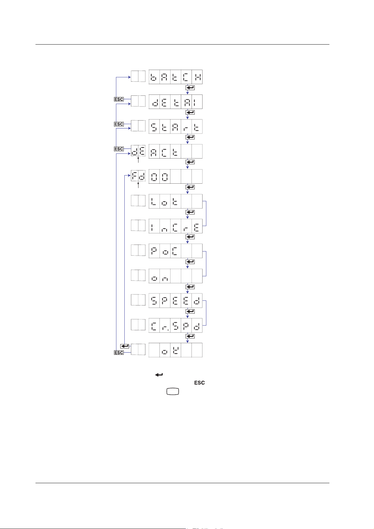
3.12 Setting Up Start Printout and End printout (/BT1 Option)
Setting the Feed Amount, Lot Number Update, and Ejection of Pen Offset
Compensating Data
(BATCH)
(DETAI)
(START)
batch details
(ACT)
feed
(LOT)
Select “BATCH.”
Select “DETAI” (Batch details).
(Start 2 and End 2 can be selected when
dual comment is set to USE)
Select a mode.
Select “ACT” (action).
Set the chart paper feed amount before
Start printout and after End printout.
(Only when the mode is End or End 2 and
the lot number is 4 or 6 digits)
Select to update the lot number when
recording stops.
(INCRE)
(Only when the mode is End or End 2 and
(POC)
pen offset compensating is ON on pen models.)
Select to eject the pen offset compensating
data when recording stops.
(ON)
(Only when pen offset compensating data
(SPEED)
ejection is ON)
Select the chart speed when ejecting the
pen offset compensating data.
(CR.SPD)
The settings are activated.
(OK)
3. Press the key to set other items.
If you are done, press the key.
4. Hold down the
key for 3 seconds to return to Operation mode.
MENU
3-16
IM 04P03B01-01E
Page 62

Explanation
3.12 Setting Up Start Printout and End printout (/BT1 Option)
Batch Number
You can enter up to 26 characters.
Lot Number
Enter using a 4 or 6 digit number. Select which number of digits to use (4 or 6) under
“Lot No.” in Basic Setting mode.
Mode
Select Start (
), End ( ), Start 2 ( ), or End 2 ( ). Start
2 and End 2 become available when you enable “Dual comment” in Basic Setting mode.
Comment
You can enter up to 32 characters.
Comment Line Number
1 to 5 lines can be printed out.
Chart Paper Feed Amount
The available setting range is 0 to 50 mm.
Lot Number Update
Update (
): Increments the lot number when recording stops.
Do not update ( ): Do not update the lot number.
Ejection of Pen Offset Compensating Data (pen model)
You can eject the portion that is not recorded when recording stops.
ON (
OFF (
): Eject
): Do not eject
Chart Speed When Ejecting Pen Offset Compensating Data (pen model)
Select the chart speed when ejecting the portion that was not recorded.
Current chart speed (
): Feeds at the specified chart speed.
450 ( ): Fixed to feed at 450 mm/h.
3
Setup Operations for Convenient Functions (Setting Mode)
IM 04P03B01-01E
Note
The following operations are performed when using the header printout function (/BT1 option).
• When the power is interrupted and is reintroduced, recording always stops. End
printout/End printout 2 is not performed.
• Until Start printout/Start printout 2 and End printout/End printout 2 finishes, the instrument
cannot transition to the next operation.
• When recording is started, the alarm and message printout information stored in the buffer
prior to recording stop is cleared.
<Related Topics> Enabling start printout and stop printout: Section 4.23
Setting the number of lot number digits and enabling start 2 printout
and stop 2 printout: Section 4.23
3-17
Page 63

3.13 Regarding the Message Format (/BT1 Option)
In the 5 message printouts, up to 35 characters can be printed out including the date/
time and measured values. Messages including measured values can be printed out
even when start printout or stop printout is disabled.
Procedure
The message format cannot be set by key operation. Set the format using the
communication command or a RXA10-03 or RXA10-04 Configuration software
(sold separately).
Explanation
Message Number
Select from 1 to 5.
Message Format
Choose a message format. Measured values, message strings, and date/time can be set
arbitrarily.
Example: Based on the message 1 string of the standard function, you can set a
combination with message format 1 and print it out as message 1 including
measured values.
Standard function
Message 1 string: Process-1°C
Message 1 printout result: 06/30 10:10 Process-1 134.8°C
Message format 1: M/D H:M L09 01L02
10th and 11th character of the message
string (9 characters already used, so this
represents the next characters)
Measured value on CH1 (no units)
Space
1-9th characters of the message string
Space (number of characters: 1)
Date/time
• Date/Time Format and Number of Characters Used
H:M (Hour:Minute) 5 characters
H:M:S (Hour:Minute:Second) 8 characters
M/D H:M (Month/Day Hour:Minute) 11 characters
M/D H:M:S (Month/Day Hour:Minute:Second) 14 characters
D/M H:M (Day/Month Hour:Minute) 11 characters
D/M H:M:S (Day/Month Hour:Minute:Second) 14 characters
D.M H:M (Day.Month Hour:Minute) 11 characters
D.M H:M:S (Day.Month Hour:Minute:Second) 14 characters
M.D H:M (Month.Day Hour:Minute) 12 characters
M.D H:M:S (Month.Day Hour:Minute:Second) 15 characters
Y/M/D H:M:S (Year/Month/Day Hour:Minute:Second) 19 characters
M/D/Y H:M:S (Month/Day/Year Hour:Minute:Second) 19 characters
D/M/Y H:M:S (Day/Month/Year Hour:Minute:Second) 19 characters
D.M.Y H:M:S (Day.Month.Year Hour:Minute:Second) 19 characters
M.D.Y H:M:S (Month.Day.Year Hour:Minute:Second) 20 characters
3-18
• Measured Value Format and Number of Characters Used
The format for measured values is 01, 02, ...06. No units are added. 7 characters are
used.
IM 04P03B01-01E
Page 64

3.13 Regarding the Message Format (/BT1 Option)
• Character String Format
The format for message strings is L01 (1 character), L02 (2 characters), .... L16 (16
characters).
In the example on the previous page, L09 indicates “Process-1” and L02 indicates “°C .”
<Related Topics> Enabling the message format: Section 4.23
Setting message strings: Section 3.8
3
Setup Operations for Convenient Functions (Setting Mode)
IM 04P03B01-01E
3-19
Page 65

3.14 Setting the Date/Time for Switching between Standard Time and DST
The date/time for switching from the standard time to DST and the date/time for
switching back from DST to standard time can be set, if the recorder is used in a region
that has DST. When the preset date/time arrives, the recorder internal clock
automatically switches.
Procedure
1. Hold down the
2. Carry out the procedure shown in the figure below.
Press the
If you press the key, the operation is cancelled, and the display returns to a
higher level menu.
key for 3 seconds to enter Setting mode.
MENU
or key to select the value.
Select the “AUX.”
(AUX)
Select “DST.”
(DST)
Select whether to use the DST function.
(USE)
Start month
(LAST)
Start week
(SUN)
Start day
Start hour
End month
(LAST)
End week
(SUN)
End day
(Displays the following when the
DST function is set to USE)
Select the start month.
Select the start week.
Select the start day.
Select the start hour.
Select the end month.
Select the end week.
Select the end day.
Select the end hour.
3-20
End hour
The settings are activated.
(OK)
IM 04P03B01-01E
Page 66
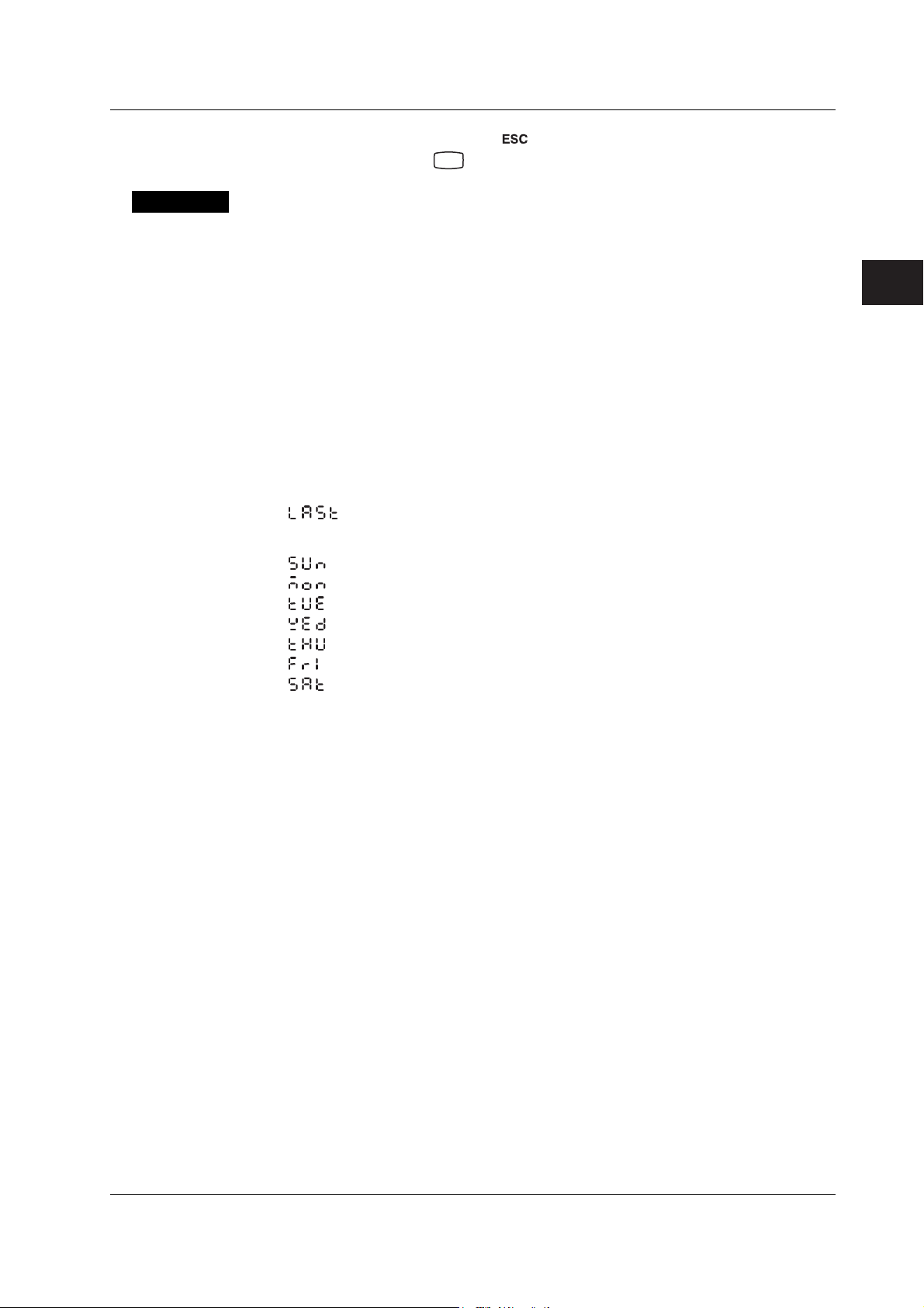
Explanation
3.14 Setting the Date/Time for Switching between Standard Time and DST
3. If you are done, press the key.
4. Hold down the
key for 3 seconds to return to Operation mode.
MENU
Start Month, Start Day, and Start Time
Set the date/time for switching from standard time to DST. Specify the day as the n
of the week of the month.
End Month, End Day, and End Time
Set the date/time for switching from DST to standard time. Specify the day as the n
of the week of the month.
Start Month and End Month
01 to 12: January to December
Start Week and End Week
st
1: 1
week
nd
2: 2
week
3: 3rd week
4: 4th week
: Last week
Start Day and End Day
: Sunday
: Monday
: Tuesday
: Wednesday
: Thursday
: Friday
: Saturday
th
th
day
day
3
Setup Operations for Convenient Functions (Setting Mode)
Start Time and End Time
00 to 23: Hour 00 to hour 23
IM 04P03B01-01E
3-21
Page 67

Chapter 4 Setup Operations for Changing/Adding Functions (Basic Setting Mode)
4.1 Changing the Auxiliary Alarm Function
This section explains the details of setting the alarm system items listed below.
• Diagnosis output using the alarm output relay (I01)
• Energized/De-energized operation of alarm output relays when alarms occur
• Alarm hysteresis
Basic Setting mode cannot be entered when recording is in progress.
Procedure
1. Hold down the
2. Hold down the and keys simultaneously for 3 seconds to display the
Basic Setting mode screen.
3. Carry out the procedure shown in the figure below.
Press the
If you press the
higher level menu.
MENU
key for 3 seconds to enter Setting mode.
or key to select the value.
key, the operation is cancelled, and the display returns to a
Select the “ALARM.”
(RANGE)
4
Setup Operations for Changing/Adding Functions (Basic Setting Mode)
Diagnosis output
(DIAG)
(ON)
(RELAY)
(ENERG)
(HYS)
(OFF)
(OK)
4. If you are done, press the key.
5. To return to the Operation mode,
1. Press the key, use the or key to select , and press the
key.
2. Press the or key to select or , and press the
key.
Select ON to set relay I01 to diagnosis
output. This setting is valid only on
models with the /A1, /A2, or /A3 option.
Output relay energize/de-energize
Select the relay’s energized or
de-energized operation. This setting is
valid only on models with the /A1, /A2,
or /A3 option.
Hysteresis
Select the hysteresis (0.0% (OFF) to
1.0%).
The settings are activated.
IM 04P03B01-01E
4-1
Page 68

4.1 Changing the Auxiliary Alarm Function
Explanation
Diagnosis Output
When set to ON, alarm output relay I01 becomes a dedicated diagnosis output relay, and
the operation is fixed to de-energized. Diagnosis output is a function which outputs a
relay signal when an error is detected in the recording section, burnout detection
function, or the A/D converter.
Output Relay Energize/De-Energize Operation
Sets whether the output relay is energized or de-energized when an alarm occurs.
Energize (
De-energize (
Hysteresis
Sets the alarm hysteresis of the measurement channels.
The hysteresis width can be set in the range of 0.0% (OFF) to 1.0% of the recording
span in 0.1 steps.
The hysteresis applies to all high limit and low limit alarms of measurement channels.
<Related Topics> Setting the alarm: Section 2.2
): Energizes the relay when an alarm occurs. The relay is de-
energized during normal operation.
): De-energizes the relay when an alarm occurs. The relay is
energized during normal operation.
4-2
IM 04P03B01-01E
Page 69

4.2 Changing the Integration Time of the A/D Converter
The integration time of the A/D converter can be set. Basic Setting mode cannot be
entered when recording is in progress.
Procedure
1. Hold down the
2. Hold down the
Basic Setting mode screen.
3. Carry out the procedure shown in the figure below.
Press the
If you press the key, the operation is cancelled, and the display returns to a
higher level menu.
MENU
key for 3 seconds to enter Setting mode.
and keys simultaneously for 3 seconds to display the
or key to select the value.
Select “INTG.”
(INTG)
Select the integration time of the
A/D converter.
(AUTO)
The settings are activated.
(OK)
4
Setup Operations for Changing/Adding Functions (Basic Setting Mode)
Explanation
4. If you are done, press the key.
5. To return to the Operation mode,
1. Press the
key, use the or key to select , and press the
key.
2. Press the or key to select or , and press the
key.
Integration Time
Selects the integration time of the A/D converter.
Selectable Settings Integration Time Scan Interval Recording Interval
(Pen Model) (Dot Model)
50 Hz ( ) 20 ms 125 ms 1 s
60 Hz ( ) 16.7 ms 125 ms 1 s
Auto ( ) 20 ms or 16.7 ms
100 ms ( )
*1 Selectable only on the dot model.
*2 Automatically switch by detecting the power supply frequency.
*3 The integration time is fixed to 20 ms if “Auto” is selected when using the DC power supply on
a model with the /P1 option.
*1
100 ms – 2.5 s
*2*3
125 ms 1 s
IM 04P03B01-01E
4-3
Page 70

4.3 Setting the Burnout Detection Function
The burnout detection function of thermocouples can be set on 1-5V or TC input
channels. Basic Setting mode cannot be entered when recording is in progress.
Procedure
1. Hold down the
2. Hold down the and keys simultaneously for 3 seconds to display the
Basic Setting mode screen.
3. Carry out the procedure shown in the figure below.
Press the
If you press the key, the operation is cancelled, and the display returns to a
higher level menu.
Channel number
MENU
key for 3 seconds to enter Setting mode.
or key to select the value.
Select “B_OUT.”
(B_OUT)
Select the channel number.
(CH1)
Select the recording operation that is
carried out when a burnout is detected.
(OFF)
The settings are activated.
(OK)
Explanation
4. Press the key to set other channels.
If you are done, press the key.
5. To return to the Operation mode,
1. Press the
key, use the or key to select , and press the
key.
2. Press the or key to select or , and press the
key.
Burnout
Selects the action taken when a burnout is detected at the 1-5V input or the
thermocouple input.
Upscale (
): Records off the scale on the 100% side.
Downscale ( ): Records off the scale on the 0% side.
OFF (
): Disables the burnout detection function.
4-4
IM 04P03B01-01E
Page 71

4.4 Setting the RJC Function on TC Input Channels
The RJC mode can be set on TC input channels. Basic Setting mode cannot be entered
when recording is in progress.
Procedure
1. Hold down the
2. Hold down the
Basic Setting mode screen.
3. Carry out the procedure shown in the figure below.
Press the
For the procedure on how to enter values or characters, see page 19 in the
Operation Guide
To change the polarity, press the
value is blinking.
If you press the key, the operation is cancelled, and the display returns to a
higher level menu.
MENU
key for 3 seconds to enter Setting mode.
and keys simultaneously for 3 seconds to display the
or key to select the value.
.
or key when the leftmost digit of the
Selects “RJC.”
(RJC)
Select the channel number.
4
Setup Operations for Changing/Adding Functions (Basic Setting Mode)
Explanation
(CH1)
(INT)
Channel number
(OK)
4. Press the key to set other channels.
If you are done, press the key.
5. To return to the Operation mode,
1. Press the
key.
2. Press the
key.
RJC
Sets the RJC mode.
Internal (
External (
): Uses the RJC function of the recorder.
): Uses an external RJC function. If external is selected, set the
key, use the or key to select , and press the
or key to select or , and press the
compensation voltage.
Select the RJC mode of the
thermocouple input.
(When external (EXT) is selected)
Set the compensation voltage when
using the external RJC function.
The settings are activated.
IM 04P03B01-01E
Compensation Voltage
Sets the compensation voltage when using an external RJC function.
The compensation voltage can be set in the range of –19999 µV to 20000 µV.
4-5
Page 72

4.5 Changing the Channel Recording Color (Dot Model)
The trend recording color on the dot model can be changed. Basic Setting mode cannot
be entered when recording is in progress.
Procedure
1. Hold down the
2. Hold down the
Basic Setting mode screen.
3. Carry out the procedure shown in the figure below.
Press the
If you press the key, the operation is cancelled, and the display returns to a
higher level menu.
Channel number
MENU
key for 3 seconds to enter Setting mode.
and keys simultaneously for 3 seconds to display the
or key to select the value.
Select “COLOR.”
(COLOR)
Select the channel number.
(CH1)
Select the recording color.
(PRPLE)
The settings are activated.
(OK)
Explanation
4. Press the key to set other channels.
If you are done, press the
5. To return to the Operation mode,
1. Press the key, use the or key to select , and press the
key.
2. Press the or key to select or , and press the
key.
Color
Sets the recording color of measurement channels.
By default, the recording colors are set as follows:
Channel 1: Purple (
Channel 2: Red ( )
Channel 3: Green ( )
Channel 4: Blue (
Channel 5: Brown ( )
Channel 6: Black ( )
)
)
key.
4-6
IM 04P03B01-01E
Page 73

4.6 Recording by Compensating for the Pen Offset along the Time Axis (Pen Model)
The pen offset along the time axis (pen model) can be compensated. Basic Setting mode
cannot be entered when recording is in progress.
Procedure
1. Hold down the
2. Hold down the
Basic Setting mode screen.
3. Carry out the procedure shown in the figure below.
Press the
If you press the key, the operation is cancelled, and the display returns to a
higher level menu.
MENU
key for 3 seconds to enter Setting mode.
and keys simultaneously for 3 seconds to display the
or key to select the value.
Select “POC.”
(POC)
Select ON to record by compensating for
(OFF)
(OK)
the pen offset along the time axis.
The settings are activated.
4
Setup Operations for Changing/Adding Functions (Basic Setting Mode)
Explanation
4. If you are done, press the key.
5. To return to the Operation mode,
1. Press the
key.
2. Press the or key to select or , and press the
key.
When pen offset compensation is turned ON, an asterisk is printed by the time on the
periodic printout.
key, use the or key to select , and press the
Note
When pen offset compensation is enabled, all pens are aligned with the reference pen (pen that
is furthest to the back: pen 2 on the 2-pen model, pen 3 on the 3-pen model, and pen 4 on the 4-
pen model) for recording. When recording is started, only the reference pen moves until the
offset is compensated. This is not a malfunction.
IM 04P03B01-01E
4-7
Page 74

4.7 Turning Printouts ON/OFF
(Selecting the Channel/Tag Printout and Turning ON/OFF the Channel,
Alarm, Recording Start, New Chart Speed, Scale, and Pen Color Printouts)
Select whether to print using channel numbers or tags and set whether to print the
various printout items. Basic Setting mode cannot be entered when recording is in
progress.
Procedure
1. Hold down the
2. Hold down the and keys simultaneously for 3 seconds to display the
Basic Setting mode screen.
3. Carry out the procedure shown in the figure below.
Press the
If you press the key, the operation is cancelled, and the display returns to a
higher level menu.
MENU
key for 3 seconds to enter Setting mode.
or key to select the value.
(PRINT)
(CH.TAG)
Select “PRINT.”
Select the channel/tag printout
Select whether to use the channel
numbers (CH) or tags (TAG) for the
printout.
(CH)
(CHPRN)
(ON)
(ALARM)
(ON1)
(RCD)
(OFF)
(SPEED)
Channel printout (Dot model only)
Select whether to print the channel
number or tag by the trend recording.
Select ON or OFF.
Alarm printout
Select whether to print the alarm
occurrence/release (ON1, ON2 or OFF).
Recording start printout
Select whether to perform recording
start printout. Select ON or OFF.
New chart speed printout
Select whether to perform new chart
speed printout. Select ON or OFF.
4-8
(ON)
To the next page
IM 04P03B01-01E
Page 75

From the previous page
4.7 Turning Printouts ON/OFF
Explanation
(SCALE)
(ON)
(PEN)
(ON)
(OK)
4. If you are done, press the key.
5. To return to the Operation mode,
1. Press the
key, use the or key to select , and press the
key.
2. Press the or key to select or , and press the
key.
Channel/Tag Printout
Channel ( ): Prints the channel number.
Tag (
): Prints the tag.
Scale printout
Select whether to print the channel scale
in periodic printout. Select ON or OFF.
Recording color printout
(pen model only)
Select whether to print the recording color
in periodic printout. Select ON or OFF.
This is valid on channels whose scale
printout is turned ON.
The settings are activated.
4
Setup Operations for Changing/Adding Functions (Basic Setting Mode)
Alarm Printout
ON1 ( ): Prints the alarm information when an alarm occurs or releases.
ON2 (
): Prints the alarm information only when an alarm occurs.
OFF ( ): Does not print alarm information.
Note
Channel, alarm, recording start, and new chart speed printouts are not performed when the
chart speed is higher than or equal to 1800 mm/h and 120 mm/h on the pen model and dot
model, respectively.
IM 04P03B01-01E
4-9
Page 76

4.8 Turning Periodic Printout ON and OFF and Setting the Interval
The periodic printout settings can be specified. Basic Setting mode cannot be entered
when recording is in progress.
Procedure
1. Hold down the
2. Hold down the and keys simultaneously for 3 seconds to display the
Basic Setting mode screen.
3. Carry out the procedure shown in the figure below.
Press the
For the procedure on how to enter values or characters, see page 19 in the
Operation Guide
If you press the key, the operation is cancelled, and the display returns to a
higher level menu.
MENU
key for 3 seconds to enter Setting mode.
or key to select the value.
.
Select “PER.”
(PER.)
Select the periodic printout interval
(AUTO)
mode.
Explanation
Set the reference time for the printout.
(00:00)
(When the interval mode is manual)
(1H)
(INST)
(OK)
4. If you are done, press the key.
5. To return to the Operation mode,
1 . Press the
key.
2. Press the
key.
Periodic Printout
Selects the periodic printout interval mode.
Auto (
Manual ( ): Set the printout interval manually.
): Automatically sets the printout interval in sync with the chart speed.
key, use the or key to select , and press the
or key to select or , and press the
Select the periodic printout interval.
Select whether to enable (INST) or
disable (OFF) the periodic printout.
The settings are activated.
4-10
Reference Time
Sets the reference time for determining the times for executing the periodic printout.
The reference time is set in the range of 00 to 23 in 1 hour steps. Minutes cannot be
specified.
IM 04P03B01-01E
Page 77

4.8 Turning Periodic Printout ON and OFF and Setting the Interval
Interval
Select the interval from 10, 12, 15, 20, 30 minutes, 1, 2, 3, 4, 6, 8, 12, and 24 hours
(
depending on the chart speed and items printed (for details, see appendix 1).
Turning ON/OFF the Periodic Printout
ON (instantaneous value) (
OFF ( ): Disables periodic printout.
to ). However, printout might not take place at the specified interval
): Prints the measured value at that point.
4
Setup Operations for Changing/Adding Functions (Basic Setting Mode)
IM 04P03B01-01E
4-11
Page 78

4.9 Setting the Key Lock
The keys that can be locked and the password for releasing the key lock can be set.
Basic Setting mode cannot be entered when recording is in progress.
Procedure
1. Hold down the
2. Hold down the and keys simultaneously for 3 seconds to display the
Basic Setting mode screen.
3. Carry out the procedure shown in the figure below.
Press the
For the procedure on how to enter values or characters, see page 19 in the
Operation Guide
If you press the key, the operation is cancelled, and the display returns to a
higher level menu.
MENU
key for 3 seconds to enter Setting mode.
or key to select the value.
.
(LOCK)
(USE)
(****)
Select “LOCK.”
Select "USE" to set the target keys of the
key lock.
(Displays the following when the target
key setting is set to USE)
Set the password.
(RCd)
(FREE)
(FEED)
(FREE)
(MENU)
(FREE)
(M_PRN)
(FREE)
RCD key
Select whether to lock the key
(LOCK or FREE).
FEED key
Select whether to lock the key
(LOCK or FREE).
MENU key
Select whether to lock the key
(LOCK or FREE).
Manual printout
Select whether to lock the key
(LOCK or FREE).
4-12
To the next page
IM 04P03B01-01E
Page 79

From the previous page
4.9 Setting the Key Lock
(LIST)
(FREE)
(SLIST)
(FREE)
(MSG)
(FREE)
(B-CLR)
(FREE)
List printout
Select whether to lock the key
(LOCK or FREE).
Setup list printout
Select whether to lock the key
(LOCK or FREE).
4
Setup Operations for Changing/Adding Functions (Basic Setting Mode)
Message printout
Select whether to lock the key
(LOCK or FREE).
Printout buffer clear
Select whether to lock the key
(LOCK or FREE).
(PEN)
Pen exchange (Pen model only)
Select whether to lock the key
(LOCK or FREE).
(FREE)
(RIBON)
Ribbon exchange (Dot model only)
Select whether to lock the key
(LOCK or FREE).
(FREE)
The settings are activated.
(OK)
4. If you are done, press the key.
5. To return to the Operation mode,
1. Press the key, use the or key to select , and press the
key.
2. Press the or key to select or , and press the
key.
IM 04P03B01-01E
4-13
Page 80

4.9 Setting the Key Lock
Explanation
Key Lock
Select the target keys (
)
Not use the key lock ( )
Password
Sets the password for releasing the key lock. Set the password using a four-digit
number.
Operation of Keys to Be Key-Locked
Sets the operation of the keys to be key-locked. Select Lock (
) or Free
( ) for each key operation.
RCD:
FEED:
MENU:
M_PRN:
LIST:
SLIST:
MSG:
B_CLR:
PEN:
RCD
key
FEED
key
MENU
key
key + manual printout operation
FUNC
key + list printout operation
FUNC
key + setup list printout operation
FUNC
key + message printout operation
FUNC
key + clear operation of the printout buffer memory
FUNC
key + the operation of moving the pen to an easily accessible position of
FUNC
replacement (pen model)
RIBON:
key + the operation carried out when replacing the ribbon cassette with
FUNC
the power turned ON (dot model)
<Related Topics> Activating/Releasing the Key Lock: “Activating/Releasing the Key
Lock” in the
Operation Guide
4-14
IM 04P03B01-01E
Page 81

4.10 Enabling the Moving Average Function (Dot Model)
The moving average function can be enabled/disabled on the dot model. Basic Setting
mode cannot be entered when recording is in progress.
Procedure
1. Hold down the
2. Hold down the
Basic Setting mode screen.
3. Carry out the procedure shown in the figure below.
Press the
If you press the key, the operation is cancelled, and the display returns to a
higher level menu.
MENU
key for 3 seconds to enter Setting mode.
and keys simultaneously for 3 seconds to display the
or key to select the value.
Select “M_AVE.”
(M_AVE)
Select whether to use moving average
(NOT)
(OK)
function.
The settings are activated.
4
Setup Operations for Changing/Adding Functions (Basic Setting Mode)
Explanation
4. If you are done, press the key.
5. To return to the Operation mode,
1. Press the
key.
2. Press the
key.
Moving Average
Enable (
Disable ( ): The “M_AVE” item does not appear in Setting mode.
<Related Topics> Setting the moving average: section 3.3
): Enables the setting of the number of samples of the moving average
in Setting mode.
key, use the or key to select , and press the
or key to select or , and press the
IM 04P03B01-01E
4-15
Page 82
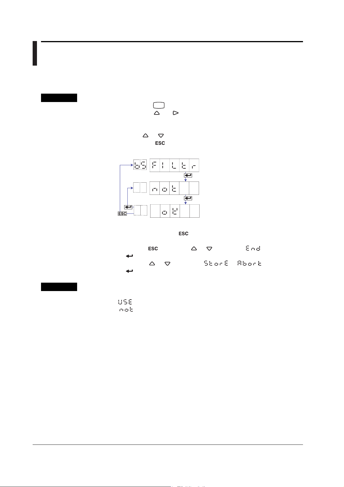
4.11 Enabling the Filter Function (Pen Model)
The input filter function on the pen model can be enabled/disabled. Basic Setting mode
cannot be entered when recording is in progress.
Procedure
1. Hold down the
2. Hold down the and keys simultaneously for 3 seconds to display the
Basic Setting mode screen.
3. Carry out the procedure shown in the figure below.
Press the
If you press the key, the operation is cancelled, and the display returns to a
higher level menu.
MENU
key for 3 seconds to enter Setting mode.
or key to select the value.
Select “FILTR.”
(FILTR)
Select whether to use the filter function.
(NOT)
The settings are activated.
(OK)
Explanation
4. If you are done, press the key.
5. To return to the Operation mode,
1. Press the key, use the or key to select , and press the
key.
2. Press the or key to select or , and press the
key.
Filter
Enable (
Disable ( ): The “FILTR” item does not appear in Setting mode.
<Related Topics> Setting the filter: Section 3.2
): Enables the setting of the filter and the time constant in Setting mode.
4-16
IM 04P03B01-01E
Page 83

4.12 Enabling the Partial Expanded Recording Function
The partial expanded recording function can be enabled/disabled. Basic Setting mode
cannot be entered when recording is in progress.
Procedure
1. Hold down the
2. Hold down the
Basic Setting mode screen.
3. Carry out the procedure shown in the figure below.
Press the
If you press the key, the operation is cancelled, and the display returns to a
higher level menu.
MENU
key for 3 seconds to enter Setting mode.
and keys simultaneously for 3 seconds to display the
or key to select the value.
Select the “PART.”
(PART)
Select whether to use the partial
expanded recording function.
(NOT)
The settings are activated.
(OK)
4
Setup Operations for Changing/Adding Functions (Basic Setting Mode)
Explanation
4. If you are done, press the key.
5. To return to the Operation mode,
1. Press the
key.
2. Press the or key to select or , and press the
key.
Partial Expanded Recording
Enable ( ): Enables the setting of the boundary position and boundary value of
the partial expanded recording function in Setting mode.
Disable (
<Related Topics> Setting the partial expanded recording: Section 3.5
): The “PART” item does not appear in Setting mode.
key, use the or key to select , and press the
IM 04P03B01-01E
4-17
Page 84

4.13 Changing the Printout Font
The printout font can be changed. Changing the font changes the characters that can be
used for message printouts, tags, and header printouts (/BT1 option). Basic Setting
mode cannot be entered when recording is in progress.
Procedure
1. Hold down the
2. Hold down the and keys simultaneously for 3 seconds to display the
Basic Setting mode screen.
3. Carry out the procedure shown in the figure below.
Press the
If you press the
higher level menu.
MENU
key for 3 seconds to enter Setting mode.
or key to select the value.
key, the operation is cancelled, and the display returns to a
(FONT)
(ENG.)
Select “FONT.”
Select the printout font.
The settings are activated.
Explanation
(OK)
4. If you are done, press the key.
5. To return to the Operation mode,
1. Press the
key, use the or key to select , and press the
key.
2. Press the or key to select or , and press the
key.
Font
English ( ): Uses the alphabet, numbers, and symbols for printout.
Japanese (
): Uses the alphabet, Katakana, numbers, and symbols for printout.
German ( ): Uses the German alphabet, numbers, and symbols for printout.
French ( ): Uses the French alphabet, numbers, and symbols for printout.
For English or Japanese For German or French
Lower
0 1 2 3 4 5 6 7 8
Upper
SP
# % (
2
0 1 2 3 4 5 6 7 8
3
@ A B C D E F G H
4
P Q R S T U V W X
5
a b c d e f g h
6
p q r s t u v w x
7
A
B
C
D
Only Japanese
9 A B C D E F
)
∗ + − . /
9
I J K L M N O
Y Z °
i j k l m n o
y z µ Ω 2 3
Lower
0 1 2 3 4 5 6 7 8
Upper
SP
# % (
2
0 1 2 3 4 5 6 7 8
3
@ A B C D E F G H
4
P Q R S T U V W X
5
a b c d e f g h
6
p q r s t u v w x
7
A
B
C
D
E
F
2 3
°
Ä Ç
Ö
à â ä ç è
ô ö
µ
Only German
Only French
9 A B C D E F
) ∗ + - . /
9
I J K L M N O
Y Z \
i j k l m n o
y z Ω
Ë Ï
Ü ß
é ê ë î ï
ù û ü
4-18
IM 04P03B01-01E
Page 85

4.14 Changing the Print/Display Format of the Date
The format of the printout and display of the year, month, and day can be changed.
Basic Setting mode cannot be entered when recording is in progress.
Procedure
1. Hold down the
2. Hold down the and keys simultaneously for 3 seconds to display the
Basic Setting mode screen.
3. Carry out the procedure shown in the figure below.
Press the
If you press the key, the operation is cancelled, and the display returns to a
higher level menu.
MENU
key for 3 seconds to enter Setting mode.
or key to select the value.
Select “DATE.”
(DATE)
Select the date format.
(YMD)
The settings are activated.
(OK)
4
Setup Operations for Changing/Adding Functions (Basic Setting Mode)
Explanation
4. If you are done, press the key.
5. To return to the Operation mode,
1. Press the key, use the or key to select , and press the
key.
2. Press the or key to select or , and press the
key.
Type
Selectable Type Printout Format Display Format Notes
Settings Example Example
Y/M/D 2006/03/31 06 03 31 Default value
M/D/Y 03/31/2006 03 31 06
D/M/Y 31/03/2006 31 03 06
D.M.Y 31.03.2006 31 03 06
M.D.Y Mar.31.2006 03 31 06
IM 04P03B01-01E
4-19
Page 86

4.15 Enabling the Bias, Low-Cut, and Calibration Correction (/CC1 Option) Functions
The bias, low-cut, and calibration correction functions can be enabled/disabled. Basic
Setting mode cannot be entered when recording is in progress.
Procedure
1. Hold down the
2. Hold down the
Basic Setting mode screen.
3. Carry out the procedure shown in the figure below.
Press the
If you press the key, the operation is cancelled, and the display returns to a
higher level menu.
MENU
key for 3 seconds to enter Setting mode.
and keys simultaneously for 3 seconds to display the
or key to select the value.
Select “PERS.”
(PERS.)
(BIAS)
(NOT)
(SQRT)
(USE)
(1-5V)
(NOT)
(CALIB)
(NOT)
Bias function
Select enable (USE) or disable (NOT).
Low-cut function of the channel on
which square root computation is
assigned
Select enable (USE) or disable (NOT).
Low-cut function of the channel on
which 1-5V signal is assigned
Select enable (USE) or disable (NOT).
Calibration correction function
(Models with the /CC1 option)
Select enable (USE) or disable (NOT).
4-20
The settings are activated.
(OK)
4. If you are done, press the key.
5. To return to the Operation mode,
1. Press the key, use the or key to select , and press the
key.
2. Press the or key to select or , and press the
key.
IM 04P03B01-01E
Page 87

Explanation
4.15 Enabling the Bias, Low-Cut, and Calibration Correction (/CC1 Option) Functions
Bias
Enable (
Disable ( ): The “BIAS” item does not appear in Setting mode.
SQRT Low-Cut
Sets the low-cut function for the square root computation.
Enable (
Disable ( ): The “SQRT” item does not appear in Setting mode.
): Enables the setting of the bias value in Setting mode.
): Enables the setting of the low-cut function when a channel is set to
square root computation in Setting mode.
1-5V Low-Cut
Sets the low-cut function for the 1-5V input.
Enable (
Disable ( ): The “1-5V” item does not appear in Setting mode.
Calibration Correction (/CC1 Option)
Enable (
Disable (
): Enables the setting of the low-cut function when a channel is set to 1-
5V in Setting mode.
): Enables the setting of the calibration correction function in Basic
Setting and Setting modes.
): The “CALIB” item does not appear in Basic Setting or Setting mode.
Note
The bias and calibration correction functions (/CC1 option) cannot be enabled simultaneously.
<Related Topics> Setting the bias value: Section 3.10
Setting the low-cut function: Section 2.1
Setting the calibration correction method and number of calibration
points: Section 4.22
Performing calibration correction: Section 3.11
4
Setup Operations for Changing/Adding Functions (Basic Setting Mode)
IM 04P03B01-01E
4-21
Page 88
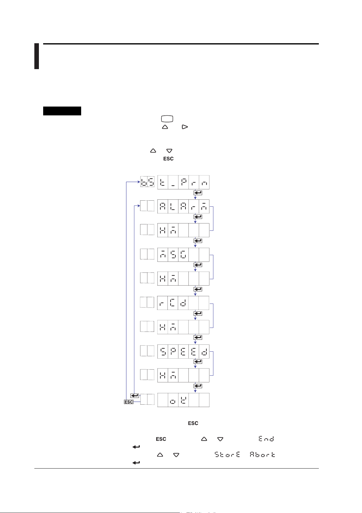
4.16 Changing the Time Printout Format
The time printout format can be changed on the alarm printout, message printout,
recording start printout, and new chart speed printout. Basic Setting mode cannot be
entered when recording is in progress.
Procedure
1. Hold down the
2. Hold down the and keys simultaneously for 3 seconds to display the
Basic Setting mode screen.
3. Carry out the procedure shown in the figure below.
Press the
If you press the
higher level menu.
MENU
key for 3 seconds to enter Setting mode.
or key to select the value.
key, the operation is cancelled, and the display returns to a
Select “T_PRN.”
(T_PRN)
(ALARM)
(HM)
(MSG)
(HM)
(RCD)
(HM)
(SPEED)
(HM)
Alarm printout
Select the time printout format.
Message printout
Select the time printout format.
Recording start printout
Select the time printout format.
New chart speed printout
Select the time printout format.
4-22
The settings are activated.
(OK)
4. If you are done, press the key.
5. To return to the Operation mode,
1. Press the key, use the or key to select , and press the
key.
2. Press the or key to select or , and press the
key.
IM 04P03B01-01E
Page 89

Explanation
4.16 Changing the Time Printout Format
Selecting the Printout Format
Select the time format of the alarm printout, message printout, recording start printout,
and new chart speed printout.
• Alarm Printout, Recording Start Printout, and New Chart Speed Printout
H:M (
H:M:S ( ): Hour:Minute:Second
M/D H:M (
M/D H:M:S ( ): Month/Day Hour:Minute:Second
Y/M/D H:M:S ( ): Year/Month/Day Hour:Minute:Second
): Hour:Minute
): Month/Day Hour:Minute
• Message Printout
H:M (
H:M:S (
M/D H:M ( ): Month/Day Hour:Minute
M/D H:M:S ( ): Month/Day Hour:Minute:Second
Y/M/D H:M:S (
NONE ( ): Does not print the date/time.
): Hour:Minute
): Hour:Minute:Second
): Year/Month/Day Hour:Minute:Second
Note
The printout format of the year, month, and day varies depending on the print/display format of
the date (see section 4.14).
4
Setup Operations for Changing/Adding Functions (Basic Setting Mode)
IM 04P03B01-01E
4-23
Page 90

4.17 Initializing the Settings
This section explains the details of initializing the recorder settings to their factory
default.
Be careful, because all settings except the date/time and the adjustment values of the
pen position and printer carriage position will be initialized. Basic Setting mode cannot be
entered when recording is in progress.
Procedure
1. Hold down the
2. Hold down the and keys simultaneously for 3 seconds to display the
Basic Setting mode screen.
3. Carry out the procedure shown in the figure below.
Press the
If you press the key, the operation is cancelled, and the display returns to a
higher level menu.
MENU
key for 3 seconds to enter Setting mode.
or key to select the value.
(INIT)
(SETUP)
Select “INIT.”
Select the range to be initialized.
Explanation
Select “YES” and press to execute
the initialization and return to Operation
(NO)
Initialization
Set (
Setup ( ): Initializes the settings in Basic Setting mode and Setting mode.
Items That Are Not Initialized
The following items are not initialized.
• Adjustment value of the pen position and the adjustment value of the printer carriage
position (Basic Setting mode)
• Date/Time (Setting mode)
): Initializes the settings in Setting mode.
mode.
4-24
IM 04P03B01-01E
Page 91

4.18 Assigning Functions to the Remote Control Input Terminals (/R1 Option)
Functions can be assigned to the remote control input terminals. Basic Setting mode
cannot be entered when recording is in progress.
Procedure
1. Hold down the
2. Hold down the and keys simultaneously for 3 seconds to display the
Basic Setting mode screen.
3. Carry out the procedure shown in the figure below.
Press the
If you press the
higher level menu.
Remote control terminal number
MENU
key for 3 seconds to enter Setting mode.
or key to select the value.
key, the operation is cancelled, and the display returns to a
Select “REM.”
(REM)
Select the remote control terminal number.
(REM1)
Select the function to be assigned.
(RCD)
4
Setup Operations for Changing/Adding Functions (Basic Setting Mode)
The settings are activated.
(OK)
4. Press the key to set other remote numbers.
If you are done, press the key.
5. To return to the Operation mode,
1. Press the
key.
2. Press the or key to select or , and press the
key.
key, use the or key to select , and press the
IM 04P03B01-01E
4-25
Page 92

4.18 Assigning Functions to the Remote Control Input Terminals (/R1 Option)
Explanation
Remote Numbers
The remote control input terminal numbers are from 1 to 5.
Functions to Be Assigned
RCD (
): Starts/stops recording.
C_SPD ( ): Changes the chart speed.
T_ADJ (
): Adjusts the internal clock to the nearest hour.
M_PRN ( ): Executes a manual printout.
MSG1 ( ): Prints message 1.
MSG2 (
): Prints message 2.
MSG3 ( ): Prints message 3.
MSG4 ( ): Prints message 4.
MSG5 (
): Prints message 5.
PR.RCD ( ): Starts/stops recording (/BT1 option).
DUAL ( ): Start printout and Start printout 2, End printout and End printout
2 switches according to the status of the “PR.RCD” signal
during the rising or falling of the “RCD” or “PR.RCD” signal (/
BT1 option).
NONE (
): No function is assigned.
Note
When you select “PR.RCD” and start recording remotely, you cannot stop recording using key
operation or communications.
<Related Topics> Setting the secondary chart speed: Section 3.9
4-26
IM 04P03B01-01E
Page 93

4.19 Selecting to Show/Hide the FUNC Key Menus
Select the menu for showing/hiding the FUNC key menus.
Basic Setting mode cannot be entered when recording is in progress.
Procedure
1. Hold down the
2. Hold down the and keys simultaneously for 3 seconds to display the
Basic Setting mode screen.
3. Carry out the procedure shown in the figure below.
Press the
If you press the key, the operation is cancelled, and the display returns to a
higher level menu.
MENU
key for 3 seconds to enter Setting mode.
or key to select the value.
Select “S.MENU.”
(S.MENU)
Select “FUNC.”
(FUNC)
4
Setup Operations for Changing/Adding Functions (Basic Setting Mode)
(M_PRN)
(ON)
(SLIST)
(ON)
(MSG)
(ON)
(B_CLR)
(ON)
Select whether to display the manual
printout FUNC key. Select ON or OFF.
Select whether to display the setup list
FUNC key. Select ON or OFF.
Select whether to display the message
FUNC key. Select ON or OFF.
Select whether to display the buffer
clear FUNC key. Select ON or OFF.
IM 04P03B01-01E
The settings are activated.
(OK)
4-27
Page 94

4.19 Selecting to Show/Hide the FUNC Key Menus
Explanation
4. If you are done, press the
key.
5. To return to the Operation mode,
1. Press the
key, use the or key to select , and press the
key.
2. Press the
or key to select or , and press the
key.
ON( ): Shows the FUNC key menu.
OFF( ): Hides the FUNC key menu when customized menu is enabled.
<Related Topics> Enabling the customized menu: Section 4.21
4-28
IM 04P03B01-01E
Page 95

4.20 Selecting to Show/Hide Setting Mode Menus
Select the menu for showing/hiding the Setting mode menus.
Basic Setting mode cannot be entered when recording is in progress.
Procedure
1. Hold down the
2. Hold down the and keys simultaneously for 3 seconds to display the
Basic Setting mode screen.
3. Carry out the procedure shown in the figure below.
Press the
If you press the key, the operation is cancelled, and the display returns to a
higher level menu.
MENU
key for 3 seconds to enter Setting mode.
or key to select the value.
Select “S.MENU.”
(S.MENU)
Select “SET.”
(SET)
4
Setup Operations for Changing/Adding Functions (Basic Setting Mode)
(RANGE)
(ON)
(BIAS)
(ON)
(ALARM)
(ON)
(UNIT)
(ON)
Select whether to display RANGE in
Setting mode. Select ON or OFF.
Select whether to display BIAS in
Setting mode. Select ON or OFF.
Select whether to display ALARM
in Setting mode. Select ON or OFF.
Select whether to display UNIT in
Setting mode. Select ON or OFF.
IM 04P03B01-01E
(CHART)
(ON)
To the next page
Select whether to display CHART
in Setting mode. Select ON or OFF.
4-29
Page 96

4.20 Selecting to Show/Hide Setting Mode Menus
From the previous page
(AUX)
(ON)
(CALIB)
(ON)
(B.NAME)
(ON)
(B.DETL)
(ON)
Select whether to display AUX in
Setting mode. Select ON or OFF.
(Models with the /CC1 option)
Select whether to display CALIB in
Setting mode. Select ON or OFF.
(Models with the /BT1 option)
Select whether to display B.NUM and
LOT menus under BATCH in Setting
mode. Select ON or OFF.
(Models with the /BT1 option)
Select whether to display DETAI
menus under BATCH in Setting mode.
Select ON or OFF.
Explanation
The settings are activated.
(OK)
4. If you are done, press the key.
5. To return to the Operation mode,
1. Press the
key, use the or key to select , and press the
key.
2. Press the or key to select or , and press the
key.
ON ( ): Shows the menu in Setting mode.
OFF ( ): Hides the menu in Setting mode when customized menu is enabled.
<Related Topics> Enabling the customized menu: Section 4.21
4-30
IM 04P03B01-01E
Page 97

4.21 Enabling/Disabling the Customized Menu
When the Customized menu is enabled, the following changes can be made.
• Hide specified menu items from the FUNC key menu.
• Hide specified Setting mode menu items.
• Lock Basic Setting mode.
Basic Setting mode cannot be entered when recording is in progress.
Procedure
Enabling the Customized Menu
1. Hold down the
2. Hold down the and keys simultaneously for 3 seconds to display the
Basic Setting mode screen.
3. Carry out the procedure shown in the figure below.
Press the
For the procedure on how to enter values or characters, see page 19 in the
Operation Guide
If you press the key, the operation is cancelled, and the display returns to a
higher level menu.
MENU
key for 3 seconds to enter Setting mode.
or key to select the value.
.
Select “CUST.M.”
(CUST.M)
4
Setup Operations for Changing/Adding Functions (Basic Setting Mode)
(USE)
(****)
Password
(P_ADJ)
(ON)
(OK)
4. If you are done, press the key.
5. To return to the Operation mode,
1. Press the
key.
2. Press the
key.
key, use the or key to select , and press the
or key to select or , and press the
Select whether to enable (USE) the
customized menu.
(Displays the following when the
customized menu is set to USE)
Set the password.
Select whether to use pen/dot printing
position adjustment without the
password. Select ON or OFF.
The settings are activated.
IM 04P03B01-01E
4-31
Page 98

4.21 Enabling/Disabling the Customized Menu
Disabling the Customized Menu
1. Hold down the
2. Hold down the
Basic Setting mode screen.
3. Carry out the procedure shown in the figure below.
Press the
For the procedure on how to enter values or characters, see page 19 in the
Operation Guide
If you press the
higher level menu.
MENU
key for 3 seconds to enter Setting mode.
and keys simultaneously for 3 seconds to display the
or key to select the value.
.
key, the operation is cancelled, and the display returns to a
Select “LOCK.”
(LOCK)
Enter the password.
(****)
Enter Basic Setting mode.
Select “CUST.M.”
(CUST.M)
Select NOT.
(NOT)
The settings are activated.
(OK)
4. If you are done, press the key.
5. To return to the Operation mode,
1. Press the
key, use the or key to select , and press the
key.
2. Press the or key to select or , and press the
key.
4-32
IM 04P03B01-01E
Page 99

Explanation
4.21 Enabling/Disabling the Customized Menu
Enable (
): Locks Basic Setting mode and hides the specified menu items in
Setting mode and FUNC key menu items.
Disable ( ): Releases Basic Setting mode and shows the all menu items in Setting
mode and all FUNC key menu items.
Password
This is the password used to release the customized menu or to enter Basic Setting
mode. Set the password using a four-digit number.
Note
Changing the Settings without Releasing the Basic Setting Mode Lock
The settings in Basic Setting mode can be changed without releasing the customized menu.
Procedure
1. Enter the password in the same manner as described in “Releasing the Customized Menu,”
and press the key. Enter Basic Setting mode.
2. Change the settings in the same manner as the normal procedure.
3. Return to Operation mode with the customized menu enabled.
<Related Topics> Selecting to show/hide the FUNC key menus: Section 4.19
Selecting to show/hide setting mode menus: Section 4.20
Adjusting the pen/dot position: Sections 6.4 and 6.5
4
Setup Operations for Changing/Adding Functions (Basic Setting Mode)
IM 04P03B01-01E
4-33
Page 100

4.22 Setting the Calibration Correction Function (/CC1 Option)
The calibration correction method and the number of correction points can be set. Basic
Setting mode cannot be entered when recording is in progress.
Procedure
1. Hold down the
2. Hold down the
Basic Setting mode screen.
3. Carry out the procedure shown in the figure below.
Press the
If you press the key, the operation is cancelled, and the display returns to a
higher level menu.
Channel number
MENU
key for 3 seconds to enter Setting mode.
and keys simultaneously for 3 seconds to display the
or key to select the value.
Select “CALIB.”
(CALIB)
Select the channel number.
(CH1)
Select whether to perform calibration
correction using revise values or
(REVIS)
absolute values.
Explanation
Set the number of calibration points.
The settings are activated.
(OK)
4. Press the key to set other channels.
If you are done, press the
5. To return to the Operation mode,
1. Press the key, use the or key to select , and press the
key.
2. Press the or key to select or , and press the
key.
Calibration Correction Method
Revise value (
Absolute value (
Number of Calibration Points
Selects the number of points that make up the segments (including the start and end
points) in the range of 2 to 16.
): Specifies the difference between the correction values
and input values.
): Specifies the correction values.
key.
4-34
<Related Topics> Enabling the calibration correction function: Section 4.15
Performing calibration correction: Section 3.11
IM 04P03B01-01E
 Loading...