

Page 1
IM 12D7J4-E/D/F-H
3rd edition
3. Ausgabe
3ème édition
Instruction Manual
Bedienungs-
anleitung
Manuel
d’Instructions
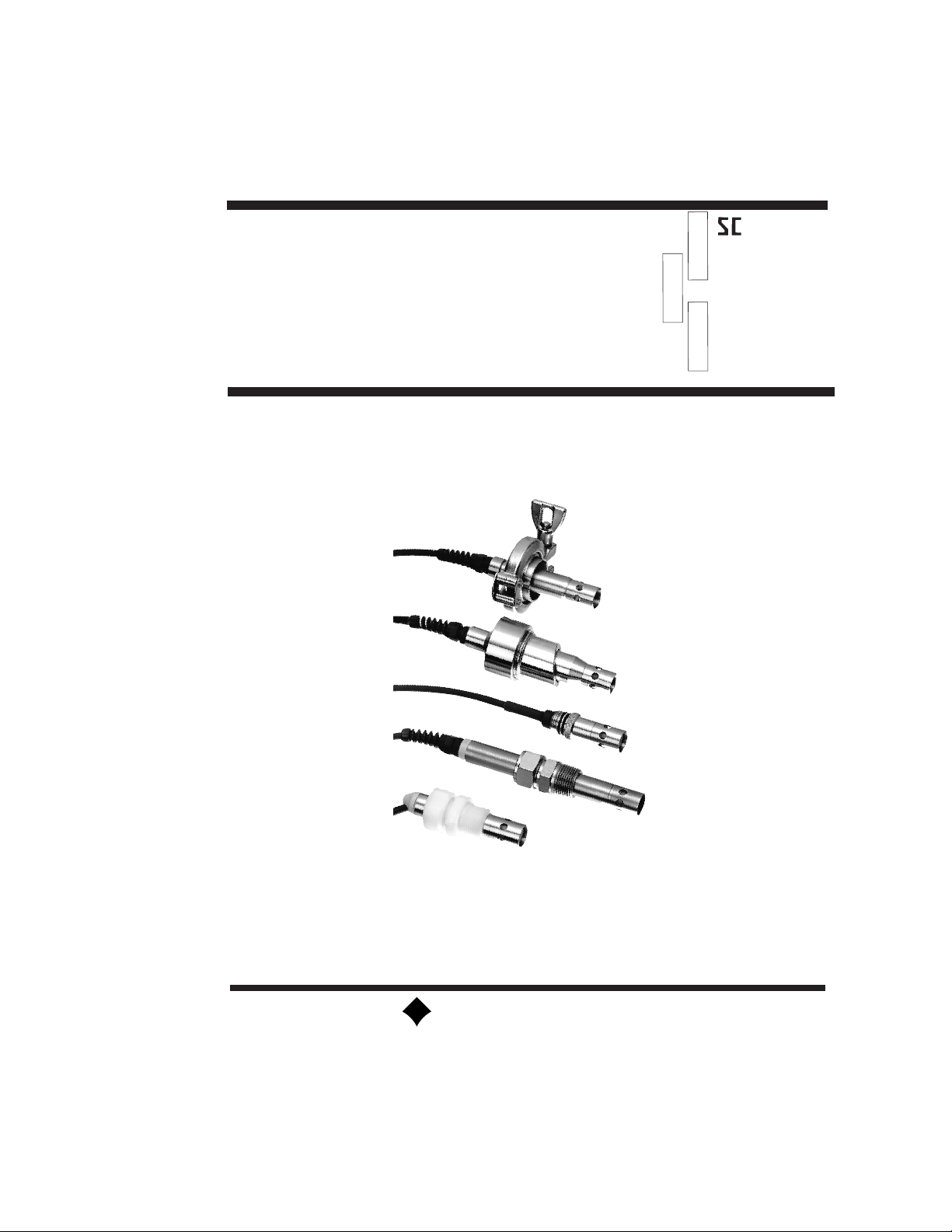
Model SC4A
19 mm Conductivity Sensor
Typ SC4A
19 mm LeitfähigkeitsSensor
Modèle SC4A
Cellule de conductivité 19 mm
ENGLISH
DEUTSCH
FRANÇAIS
YOKOGAWA
Page 2

Page 3

ENGLISH
IM 12D7J4-E/D/F-H
TABLE OF CONTENTS
1. GENERAL.......................................................................................................................1
1-1. Dimensions.............................................................................................................1
1-2. Type number..........................................................................................................1
1-3. Specifications.........................................................................................................1
1-4. Model specifications ..............................................................................................2
1-5. Labelling .................................................................................................................3
2. INSTALLATION..............................................................................................................6
2-1. connection .............................................................................................................6
2-2. Mounting................................................................................................................6
2-3. Safety warning........................................................................................................6
3. OPERATION AND MAINTENANCE..............................................................................7
3-1. Checking the cell....................................................................................................7
3-2. Calibration of the cell..............................................................................................7
3-3. Cleaning of the cell.................................................................................................7
3-4. Spare parts list.......................................................................................................7
Page 4

DEUTSCH
INHALTANGABE
1. ALLGEMEINES ..............................................................................................................9
1-1. Abmessungen........................................................................................................9
1-2. Typ-Nummer..........................................................................................................9
1-3. Technische Daten...................................................................................................9
1-4. Typ- und Zusatzcodes .........................................................................................10
1-5. Beschriftung.........................................................................................................11
2. INSTALLATION............................................................................................................14
2-1. Anschluß ..............................................................................................................14
2-2. Montage...............................................................................................................14
2-3. Sicherheitshinweise..............................................................................................14
3. BETRIEB UND WARTUNG..........................................................................................15
3-1. Prüfen der Zelle....................................................................................................15
3-2. Kalibrierung der Zelle ............................................................................................15
3-3. Reinigung der Zelle...............................................................................................15
3-4. Ersatzteilliste.........................................................................................................15
Page 5

IM 12D7J4-E/D/F-H
TABLE DES MATIERES
1. GENERALITES.............................................................................................................17
1-1. Encombrement.....................................................................................................17
1-2. Type.....................................................................................................................17
1-3. Spécifications.......................................................................................................17
1-4. Spécifications du modèle .....................................................................................18
1-5. Identification.........................................................................................................19
2. INSTALLATION............................................................................................................22
2-1. Raccordement......................................................................................................22
2-2. Montage...............................................................................................................22
2-3. Précautions de sécurité........................................................................................22
3. EXPLOITATION ET MAINTENANCE..........................................................................23
3-1. Vérification de la cellule ........................................................................................23
3-2. Etalonnage de la cellule ........................................................................................23
3-3. Nettoyage.............................................................................................................23
3-4. Pièces détachées.................................................................................................23
FRANÇAIS
Page 6

IM 12D7J4-E/D/F-H
Page 7
IM 12D7J4-E/D/F-H
1
ENGLISH
1. GENERAL
1-1. Dimensions
Installation dimensions and basic construction details of the conductivity cells are shown in
fig.1.
1-2. Type number
The type number of the conductivity cell, shown on the cable, gives coded information on
the cell constant, the materials of construction etc.
1-3. Specifications
General specifications
Wetted parts materials
a. body & electrodes : Stainless steel AISI 316 or Titanium
b. insulations : PEEK
c. mounting adapter : PVDF or Stainless steel
Operating Specifications (Sensor)
Measuring system : 2-electrode
Maximum pressure : 10 Bar
Maximum temperature : 110° C
Temperature response : < 1 minute for 90% of a step change
Sterilize : At 135° C
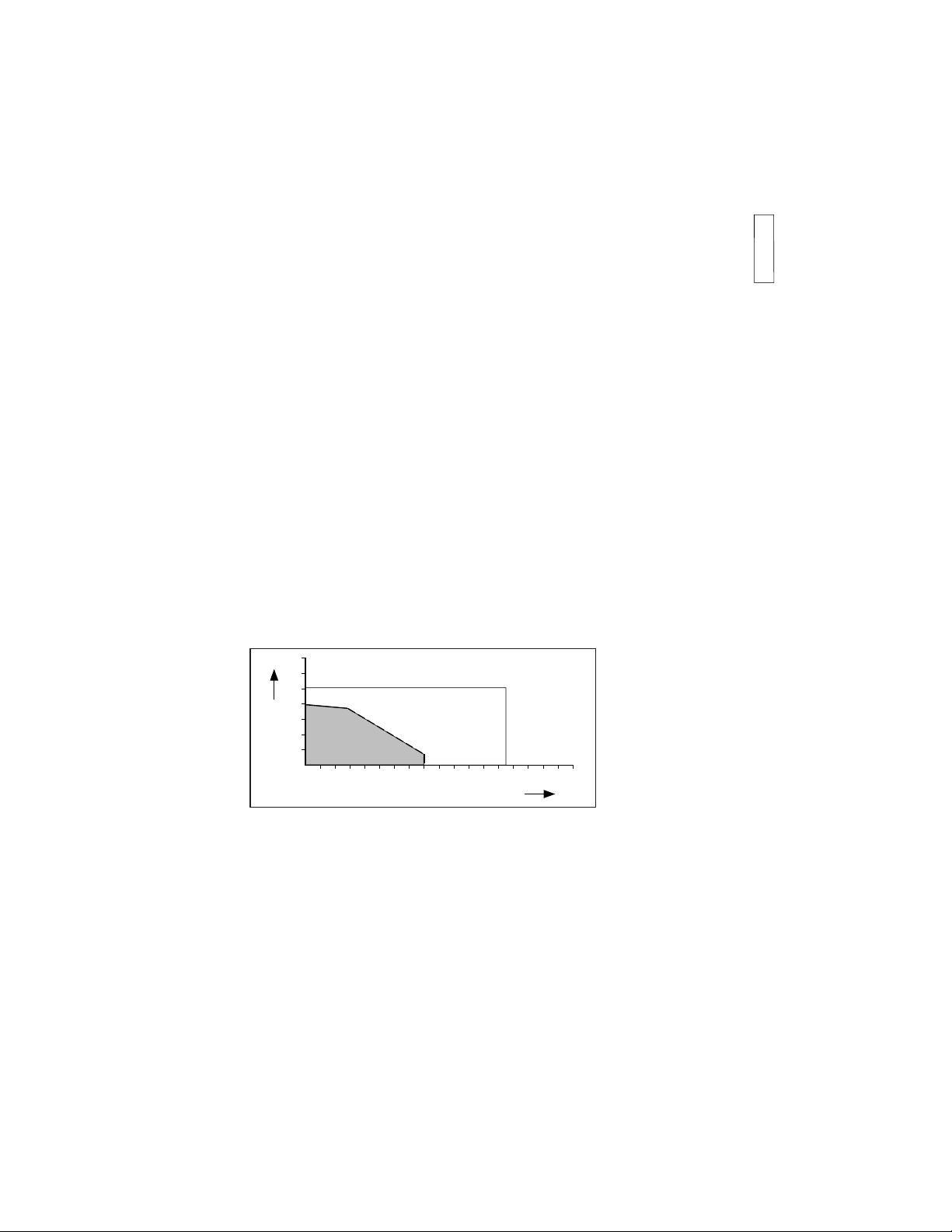
Operating Specifications (Adapters)
See fig.1.0
0 10 20 30 40 50 60 70 80 100 120 140 160
BAR
ºC
2
4
6
8
10
12
SS
PVDF
Figure 1-0. Process/temperature relationship
Page 8
IM 12D7J4-E/D/F-H
2
ENGLISH
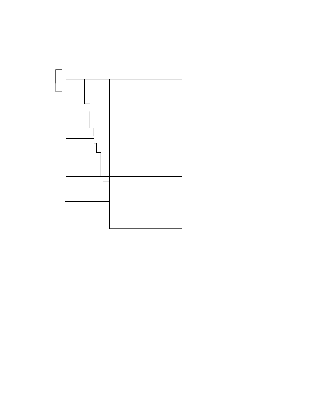
Model Suffix Option Description
Code code
SC4A 19 mm conductivity sensor
-T ................. Titanium
-S ................. Stainless steel
Fitting-type -AD ................. For adapter mounting
-PR ................. For retractable mounting
-SA ................. For sanitary purposes
-SB ................. 1-1
1/2
” tri-clamp
-SC ................. 2” tri-clamp
Sensor-length -09 ................. 9 cm
All others -15 ................. 15 cm
AD only -NN ................. fixed length
Cell constant -002 ................. 0.02/cm
-010 ................. 0.1/cm
Cable length -03 ................. 3 meter
-05 ................. 5 meter
-10 ................. 10 meter
-15 ................. 15 meter
-20 ................. 20 meter
-T1................. Pt1000
AD only /PS ........... 1” stainless steel adapter
/PF........... 1” PVDF adapter
SA only /SA1......... Straight welding socket
/SA2 ......... Angle welding socket 15º
SB only /SB1 ......... Welding clamp 1”
/SB2......... Welding clamp 1
1/2
”
SC only /SC1......... Welding clamp 2”
Certificates /M ............ 3.1.B material certificate
/Q............. Quality Inspection Certificate
1-4. Model specifications
Page 9
IM 12D7J4-E/D/F-H
3
ENGLISH
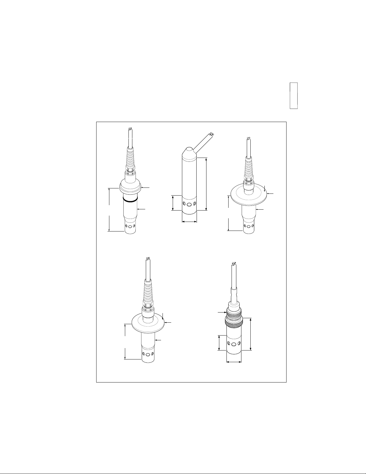
1-5. Labelling
In addition to the type number, information is given regarding:
- The batch number (e.g. P7). This number should be quoted in any service or maintenance
queries.
- Individual cell constant calibration.
Ø19,1
(0.75)
90 (3.55)
26 (1.0)
-SA
2 " tri-clamp
Ø 25
(1.00")
Ø63,9
(2.52")
80 (3.15")
1 - 1.5 " tri-clamp
Ø50,4
(1.98")
Ø21
(0.82")
70 (2.75")
-SB
-SC
47 (1.85)
26 (1.0)
Ø19,1
(0.75)
M19x1.5
standard for
PR20 mounting
-PR
or 150 (4.72)
-AD
Figure 1-1.
Ø 38 x 5
(1.50 x 0.20)
95 (3.74")
Ø 25
(1.00")
Page 10
IM 12D7J4-E/D/F-H
4
ENGLISH
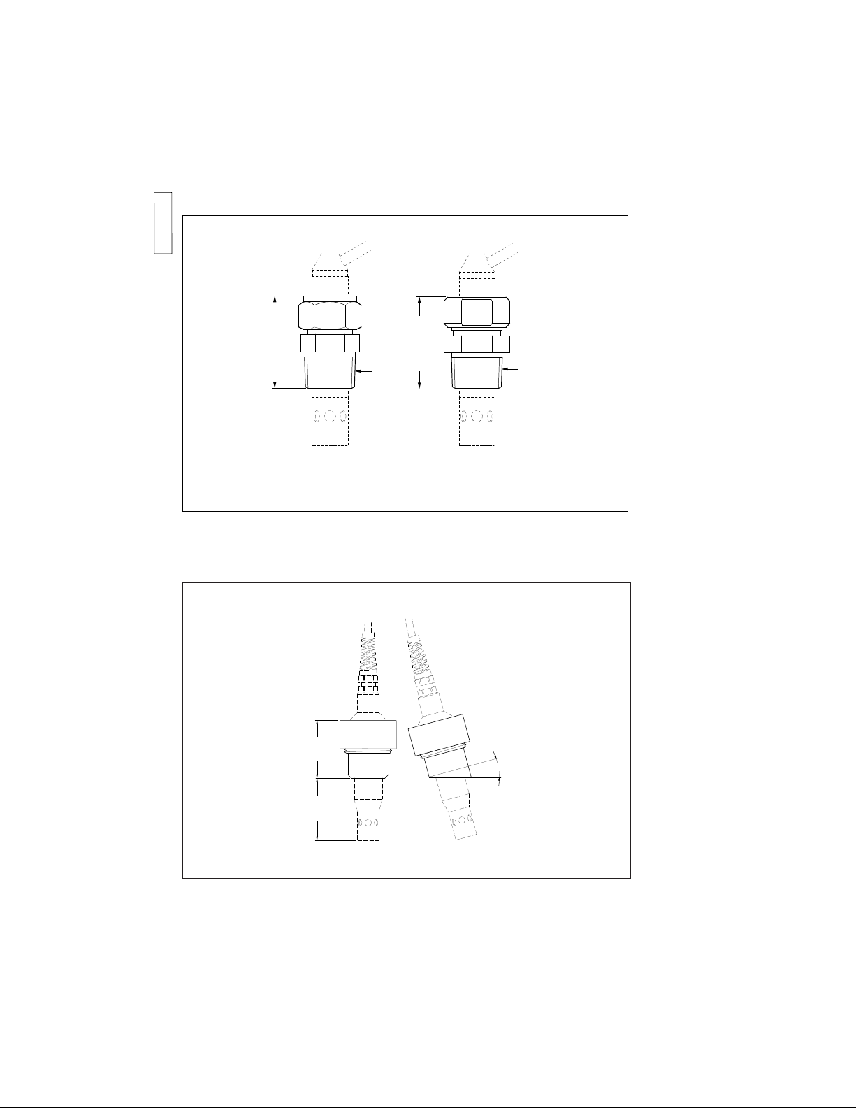
Figure 1-2. Adapters for SC4Ak-AD...
Figure 1-3. Weld sockets for SC4Ak-SA...
12D7J4-16
OPTIONS /SA1 & /SA2
/SA1
/SA2
15º
51 (2.00")
55 (2.16")
OPTIONS
ca 49 (1.95")
/PS
3/4 NPT
ca 49 (1.95")
3/4 NPT
/PF
Page 11

IM 12D7J4-E/D/F-H
5
ENGLISH
Figure 1-4. Tri-clamps
/SB2
/SC1
/SB1
12,7 (0.5")
Ø25,4(1.0")
12,7 (0.5")
Ø38,1(1.5")
12,7 (0.5")
Ø50,8(2.0")
Tri-clamps for SC4Ak-SB...
Tri-clamps for SC4Ak-SC...
Page 12

IM 12D7J4-E/D/F-H
6
ENGLISH
2. INSTALLATION
2-1. Connection
The cable is six wire multicore and covered
with a thermoplastic TPE. The wires are
also covered with thermoplastic TPE individually and coloured. The cable connections
are supplied with 2 mm terminations for
connection to the transmitter, or connection box: these pins quarantee a correct
and simple connection to the terminals.
At the instrument end the cable termination
tags are numbered to correspond with their
respective terminals of the transmitters.
NOTE:
If the cable is used with a connection box,
type BA10 (BP10 for Intrinsically Safe applications) then special purpose cable, type
WF10 must be used between connection
box and transmitter connected to the same
terminals as the cell cable. A maximum
of 50 metres total cable length is permissable.
2-2. Mounting
The mounting is by a compression gland or
sanitary adapter, giving a simple effective
method of direct insertion in process
pipework. For mounting the retractable
sensor refer to the instruction manual of
the PR4A retractable holder.
Before mounting a cell in a process plant
environment the following points should be
considered:
- a good, representative, flow of process
liquid through the cell should exist.
Hence, the cell must be mounted in the
process in such a way that the flow
through it represents the true composition
of the liquid. The flow through the cell
should be uninterrupted and the cell
should not be mounted at a “dead”
angle.
- a cell must be immersed in the process
liquid to a level above the outlet to ensure
an uninterrupted liquid path between the
electrodes.
Figure 2-1. WF10 Cable
overall
shield
screen
B
E
A
C
D
- the cell should be mounted in such a
way to allow easy removal for maintenance. It is recommended that the cell is
mounted in a ‘by-pass’ directly behind a
drain valve.
2-3. Safety warning
For SC4A..AD to avoid the sensor shooting out, never install in application where
pressure can exceed specified maximum.
Never loosen mounting nut while system is
pressurised.
Page 13

IM 12D7J4-E/D/F-H
ENGLISH
7
3. OPERATION AND MAINTENANCE
3-1. Checking the cell
If a fault occurs, first check the cell for visible damage. If damage is not apparent,
check the cell resistances measuring
between the cable connections.
a. 11 and 12 (or connector pins 1 and 2)
b. 11 and 13 (or connector pins 1 and 3)
c. 12 and 13 (or connector pins 2 and 3)
d. 12 and 15 (or connector pins 4 and 5)
e. 15 and 16 (or connector pins 5 and 6)
f. 13 and 14 (or connector pins 3 and 4)
g. 13 and 15 (or connector pins 3 and 5)
Celltype a b c d e f g
SC4A Pt1000 > 100 > 100 > 100 0 0 >100
value MΩ MΩ MΩ MΩ MΩ MΩ
If the cell has become fouled resistance will
be developed across the electrodes. These
resistances can be measured as shown in
fig. 3-1 by making contact directly with the
electrode and the relevant pin of the connector.
3-2. Calibration of the cell
The cell constant is determined in laboratory conditions. It is possible that slight variations in the cell constant may occur dependant on the installation. This possible error
can be corrected by recalibrating with a
solution of known conductivity value
(according to DIN 53779).
NOTES:
The specific conductivity value of the solution of known value must be near the value
of the liquid to be measured. Specific conductivity is highly temperature dependent,
therefore in the above calibration procedure
the temperature of the cell and the liquid
should be allowed to equalise and should
be accurately measured with a calibrated
thermometer.
3-3. Cleaning of the cell
If the cell becomes fouled an insulating
layer may be formed on the electrodes and
consequently, an apparent increase in cell
constant may accur, giving a measuring
error. This error is:
2 • x 100 %
Where:
Rv = the resistance of the fouling layer
Rcel = the cell resistance.
Cleaning methods
1. For normal applications hot water with
domestic washing-up liquid added will
be effective.
2. For lime, hydroxides, etc. a 5...10%
solution of hydrochloric acid is recommended.
3. Organic foulings (oils, fats, etc.) can be
easily removed with acetone.
4. For algae bacteria or moulds, use a
chlorinated solution (domestic bleach*).
* Never use hydrochloric acid and
domestic bleach simultaneously. The
liberation of the very poisonous gas
chlorine will result.
3-4. Spare parts list
Spare part nr. Description
K1500BE O-ring set -PR
K1542DK O-ring set -SA
K1542DG Seal rings -SB1
K1542DH Seal rings -SB2
K1542DJ Seal ring -SC1
K1542DF 1” Stainless steel
adapter
K1542CW 1” PVDF Adapter
K1520EK Angled welding socket
15º
K1520EJ Straight weld in adapter
K1542FC Welding clamp 1”
K1542FF Welding clamp 1
1/2
”
K1542FE Welding clamp 2”
(Rv)
(Rcel)
Page 14

IM 12D7J4-E/D/F-H
8
Page 15

IM 12D7J4-E/D/F-H
DEUTSCH
1. ALLGEMEINES
1-1. Abmessungen
Installationsabmessungen und grundlegende Konstruktionsdetails der Leitfähigkeitszellen
sind in Abbildung 1 dargestellt.
1-2. Typ-Nummer
Die Typ-Nummer der Leitfähigkeitszelle, die auf dem Kabel angegeben ist, enthält codierte Informationen zur Zellkonstanten, zu Konstruktionsmaterialien etc.
1-3. Technische Daten
Allgemeine technische Daten
Material der medienberührten Teile
a. Gehäuse und Elektroden : Edelstahl AISI 316 oder Titan
b. Isoliermaterialen : PEEK
c. Montageadapter : PVDF oder Edelstahl
Betriebsdaten (Sensor)
Meßsystem : 2-Elektrodensystem
Maximaler Druck : 10 bar
Maximale Temperatur : 110° C
Temperaturantwort : < 1 Minute für 90% Sprungantwort
Sterilisierung bei : 135° C
Betriebsdaten (Adapter)
Sieh abbildung. 1.0
9
0 10 20 30 40 50 60 70 80 100 120 140 160
BAR
ºC
2
4
6
8
10
12
SS
PVDF
Abbildung 1.0. Druck/Temperatur-Klassifizierung
Page 16

IM 12D7J4-E/D/F-H
1
DEUTSCH
Typ- Zusatz- Options - Beschreibung
Code code code
SC4A 19 mm Leitfähigkeitssensor
-T ................. Titan
-S ................. Edelstahl
Armaturtyp -AD ................. Für Adaptermontage
-PR ................. Für Wechselarm.-Montage
-SA ................. Für Sanitäranwendungen
-SB ................. 1-1
1/2
” Tri-clamp
-SC ................. 2” Tri-clamp
Sensorlänge -09 ................. 9 cm
Alle anderen -15 ................. 15 cm
Nur AD -NN ................. feste Länge
Zellkonstante -002 ................. 0,02/cm
-010 ................. 0,1/cm
Kabellänge -03 ................. 3 Meter
-05 ................. 5 Meter
-10 ................. 10 Meter
-15 ................. 15 Meter
-20 ................. 20 Meter
-T1................. Pt1000
Nur AD /PS ........... 1” Edelstahladapter
/PF........... 1” PVDF-Adapter
Nur SA /SA1......... Schweißmuffe, gerade
/SA2 ......... Schweißmuffe, 15º-Winkel
Nur SB /SB1 ......... Schweißschelle 1”
/SB2......... Schweißschelle 1
1/2
”
Nur SC /SC1......... Schweißschelle 2”
Zertifikaten /M ............ 3.1.B Materialzertifikate
/Q............. Qualitätszertifikat
10
1-4. Typ- und Zusatzcodes
Page 17

IM 12D7J4-E/D/F-H
1
DEUTSCH
11
1-5. Beschriftung
Zusätzlich zur Typ-Nummer werden die folgenden Informationen angegeben:
- die Chargen-Nummer (z.B. P15). Diese Nummer sollte bei allen Service- oder Wartungsanfragen angegeben werden
- Kalibrierung der individuellen Zellkonstanten.
Ø19,1
(0.75)
90 (3.55)
26 (1.0)
-SA
2 " tri-clamp
Ø 25
(1.00")
Ø63,9
(2.52")
80 (3.15")
1 - 1.5 " tri-clamp
Ø50,4
(1.98")
Ø21
(0.82")
70 (2.75")
-SB
-SC
47 (1.85)
26 (1.0)
Ø19,1
(0.75)
M19x1.5
standard for
PR20 mounting
-PR
oder 150 (4.72)
-AD
Abbildung 1-1.
M 19 x 1,5
Standard für
PR20-Montage
Ø 38 x 5
(1.50 x 0.20)
95 (3.74")
Ø 25
(1.00")
Page 18

IM 12D7J4-E/D/F-H
1
DEUTSCH
12
/PS
3/4 NPT
OPTIONS
ca 49 (1.95")
/PF
3/4 NPT
ca 49 (1.95")
Abbildung 1-2. Adapter für SC4Ak-AD...
Abbildung 1-3. Schweißmuffen für SC4Ak-SA...
12D7J4-16
OPTIONS /SA1 & /SA2
/SA1
/SA2
15º
51 (2.00")
55 (2.16")
OPTIONEN
Page 19

IM 12D7J4-E/D/F-H
1
DEUTSCH
13
Abbildung 1-4. Tri-clamps
/SB2
/SC1
/SB1
12,7 (0.5")
Ø25,4(1.0")
12,7 (0.5")
Ø38,1(1.5")
12,7 (0.5")
Ø50,8(2.0")
Tri-clamps für SC4Ak-SB...
Tri-clamps für SC4Ak-SC...
Page 20

IM 12D7J4-E/D/F-H
1
DEUTSCH
14
2. INSTALLATION
2-1. Anschluß
Das Kabel ist ein mehradriges Kabel mit
sechs Leitungen mit einer Außenisolierung
aus thermoplastischem TPE. Die Isolierungen der einzelnen Leiter bestehen ebenfalls
aus thermoplastischem TPE und sind farbig. Die Leitungsenden verfügen über
2 mm-Anschlüsse für die Verbindung mit
dem Meßumformer oder der Anschlußbox:
diese Anschlüsse gewährleisten eine einfache und ordnungsgemäße Verbindung mit
den Klemmen.
Die Kabelanschlüsse sind am geräteseitigen Ende numeriert und korrespondieren
mit den entsprechenden Klemmen im
Meßumformer.
HINWEIS:
Wird das Kabel mit einer Anschlußbox Typ
BA10 (BP10 für eigensichere Anwendungen) verwendet, ist das Spezialkabel WF10
zwischen Anschlußbox und Meßumformer
zu verwenden, wobei die gleichen Klemmen wie beim Sensorkabel zu verwenden
sind. Zulässig ist eine maximale Gesamtlänge von 50 Metern.
2-2. Montage
Die Montage erfolgt mittels einer Klemmbuchse oder einem Sanitäradapter, was eine einfache und effektive Möglichkeit des
Direkteinbaus in die Prozeßrohrleitung darstellt. Zur Montage des Sensors für die
Wechselarmatur siehe Bedienungsanleitung
der Wechselarmatur PR4A.
Bevor eine Meßzelle in einer Prozeßumgebung montiert wird, sollten die folgenden
Punkte berücksichtigt werden:
- es sollte ein guter und repräsentativer
Fluß des Prozeßmediums durch die Zelle
gegeben sein. Daher ist die Zelle so im
Prozeß zu montieren, daß der Durchfluß
die wirkliche Zusammensetzung der Prozeßflüssigkeit repräsentiert. Der Durchfluß durch die Zelle sollte nicht unterbrochen werden und die Zelle sollte nicht in
einem „toten Winkel“ montiert werden.
- eine Zelle muß bis zu einem Pegel oberhalb des Auslaufs in die Prozeßflüssigkeit
eingetaucht sein, um eine ununterbroche-
Abbildung 2-1. WF10-Kabel
overall
shield
screen
B
E
A
C
D
ne Flüssigkeitsbrücke zwischen den
Elektroden zu gewährleisten.
- die Zelle sollte so montiert sein, daß sie
bei Wartungsarbeiten leicht entnommen
werden kann. Wir empfehlen, die Zelle in
einem „Bypass“ direkt hinter einem Ablaßventil zu montieren.
2-3. Sicherheitshinweise
Um beim SC4A..AD das Zerspringen des
Sensors zu verhindern, darf er nie in einer
Anwendung installiert werden, in der der
Druck das spezifizierte Maximum übersteigen kann. Lösen Sie nie die Montagemutter, wenn das System noch unter Druck
steht.
Abschirmung
GesamtAbschirmung
Page 21

IM 12D7J4-E/D/F-H
1
DEUTSCH
15
3. BETRIEB UND WARTUNG
3-1. Prüfen der Zelle
Wenn Fehler auftreten, prüfen Sie zunächst
die Zelle auf sichtbare Beschädigungen.
Kann keine Beschädigung festgestellt werden, prüfen Sie die Zellwiderstände, indem
Sie zwischen den Kabelanschlüssen messen:
a. 11 und 12 (oder Anschlußpins 1 und 2)
b. 11 und 13 (oder Anschlußpins 1 und 3)
c. 12 und 13 (oder Anschlußpins 2 und 3)
d. 12 und 15 (oder Anschlußpins 4 und 5)
e. 15 und 16 (oder Anschlußpins 5 und 6)
f. 13 und 14 (oder Anschlußpins 3 und 4)
g. 13 und 15 (oder Anschlußpins 3 und 5)
Zelltyp a b c d e f g
SC4A Pt1000 > 100 > 100 > 100 0 0 >100
Wert MΩ MΩ MΩ MΩ MΩ MΩ
Ist die Zelle gefault, bildet sich über den
Elektroden ein Widerstand. Dieser Widerstand kann gemessen werden, indem ein
direkter Kontakt mit der Elektrode hergestellt und der Widerstand zwischen Elektrode und dem entsprechenden Anschluß gemessen wird.
3-2. Kalibrierung der Zelle
Die Zellkonstante wird unter Laborbedingungen ermittelt. Abhängig von der Installation besteht die Möglichkeit, daß leichte
Abweichungen von der Zellkonstanten vorkommen. Dieser mögliche Fehler kann
durch Rekalibrierung mit eine Lösung mit
bekannter Leitfähigkeit (gemäß DIN 53779)
korrigiert werden.
HINWEISE:
Der Wert der spezifischen Leitfähigkeit der
Kalibrierungslösung muß in der Nähe des
Wertes der zu messenden Prozeßflüssigkeit
liegen. Die spezifische Leitfähigkeit ist sehr
stark temperaturabhängig, daher sollte
beim obigen Kalibrierverfahren gewartet
werden, bis sich die Temperatur von Zelle
und Flüssigkeit angeglichen haben, und sie
sollte dann mit einem geeichten Thermometer exakt gemessen werden.
3-3. Reinigung der Zelle
Ist die Zelle gefault, kann sich auf den
Elektroden eine isolierende Schicht bilden
und demzufolge kann sich ein deutlicher
Anstieg der Zellkonstanten ergeben, der
einen Meßfehler verursacht. Dieser Fehler
beträgt:
2 • x 100 %
Where:
Rv = Widerstand der Faulschicht
R
Zelle
= Zellwiderstand.
Reinigungsverfahren
1. Für normale Anwendungen ist heißes
Wasser mit Haushaltsspülmitteln gut
geeignet.
2. Für Kalk, Hydroxide, etc. wird eine
5...10%-ige Salzsäurelösung empfohlen.
3. Organische Faulrückstände (Öle, Fette,
etc.) können einfach mit Azeton entfernt
werden.
4. Für Algenbakterien oder Schimmel ist
eine chlorierte Lösung (HaushaltsBleichmittel* ) zu verwenden.
* Verwenden Sie Salzsäure und
Haushalts-Bleichmittel niemals
gleichzeitig. Dabei entwickelt sich
das äußerst giftige Chlorgas.
3-4. Ersatzteilliste
Ersatzteilnr. Beschreibung
K1500BE O-Ring-Satz-PR
K1542DK O-Ring-Satz-SA
K1542DG Dichtringe -SB1
K1542DH Dichtringe -SB2
K1542DJ Dichtring -SC1
K1542DF 1” Edelstahladapter
K1542CW 1” PVDF- Adapter
K1520EJ Schweißmuffe gerade
K1520EK Schweißmuffe gerade
15°-winkel
K1542FC Schweißschnelle 1”
K1542FF Schweißschnelle 1
1/2
””
K1542FE Schweißschnelle 2”
(Rv)
(R
Zelle
)
Page 22

IM 12D7J4-E/D/F-H
16
Page 23

IM 12D7J4-E/D/F-H
17
FRANÇAIS
1. GENERALITES
1-1. Encombrement
La figure 1 indique l’encombrement et les caractéristiques de construction de la cellule.
1-2. Type
Le type de la cellule indiqué sur le câble donne des indications codées sur la constante
de cellule, les matériaux, etc.
1-3. Spécifications
Spécifications générales.
Matériaux des pièces en contact avec le fluide
a. corps et électrodes : acier inoxydable AISI 316 ou Titane
b. pièces isolantes : PEEK
c. adaptateur : PVDF ou acier inoxydable
Spécifications de fonctionnement du capteur
Système de mesure : à 2-électrodes
Pression max. : 10 Bar
Température max. : 110° C
Réponse de température : < 1 minute pour une modification à 90%
Stérilisation : à 135°C
Spécifications de fonctionnement des adaptateurs
Relation pression/température
Pression max. : 1 Bar 6 Bar
Température max : 80 °C 20 °C
Acier inoxydable
Pression max. : 10 Bar
Température max. : 110 °C
Page 24

IM 12D7J4-E/D/F-H
18
FRANÇAIS
1-4. Spécifications du modèle
Code du Code Option Description
Modèle suffixe
SC4A ................. cellule de conduct. 19mm
-T ................. Titane
-S ................. Acier inoxydable
Type de -AD ................. pour adaptateur
sonde -PR ................. pour sonde rétractable
-SA ................. application alimentaire
-SB ................. 1-1
1/2”
tri-clamp
-SC ................. 2” tri-clamp
Long. capteur -09 ................. 9 cm
Tous -15 ................. 15 cm
AD -NN ................. longueur fixe
Const. cellule -002 ................. 0.02/cm
-010 ................. 0.1/cm
Long. câble -03 ................. 3 mètres
-05 ................. 5 mètres
-10 ................. 10 mètres
-15 ................. 15 mètres
-20 ................. 20 mètres
-T1................. Pt1000
AD seulement /PS........... Adapt. 1” acier inox.
/PF........... Adapt. 1” PVDF
SA seulement /SA1 ......... Raccord soudé droit
/SA2 ......... Raccord soudé 15º
SB seulement /SB1......... tri clamp 1”
/SB2......... tri clamp 1 1/2 ”
SC seulement /SC1......... tri clamp 2”
Certificats /M ............ 3.1.B certificat matière
/Q............. Certificat Qualité
Page 25

IM 12D7J4-E/D/F-H
19
FRANÇAIS
1-5. Identification
Informations supplémentaires:
- numéro de lot (ex. P7). Toujours rappeler ce numéro dans toute correspondance avec le
service après-vente.
- étalonnage de la constante de cellule.
Ø19,1
(0.75)
90 (3.55)
26 (1.0)
-SA
2 " tri-clamp
Ø 25
(1.00")
Ø63,9
(2.52")
80 (3.15")
1 - 1.5 " tri-clamp
Ø50,4
(1.98")
Ø21
(0.82")
70 (2.75")
-SB
-SC
47 (1.85)
26 (1.0)
Ø19,1
(0.75)
M19x1.5
standard for
PR20 mounting
-PR
or 150 (4.72)
Standard pour
montage
PR20
-AD
Figure 1-1.
Ø 38 x 5
(1.50 x 0.20)
95 (3.74")
Ø 25
(1.00")
Page 26

IM 12D7J4-E/D/F-H
20
FRANÇAIS
Figure 1-2. Adaptateurs pour SC4Ak-AD...
Figure 1-3. Raccords soudés pour SC4Ak-SA...
12D7J4-16
OPTIONS /SA1 & /SA2
/SA1
/SA2
15º
51 (2.00")
55 (2.16")
OPTIONS
ca 49 (1.95")
3/4 NPT
/PS
ca 49 (1.95")
3/4 NPT
/PF
Page 27

IM 12D7J4-E/D/F-H
21
FRANÇAIS
Figure 1-4. Tri-clamps
/SB2
/SC1
/SB1
12,7 (0.5")
Ø25,4(1.0")
12,7 (0.5")
Ø38,1(1.5")
12,7 (0.5")
Ø50,8(2.0")
Tri-clamps pour SC4Ak-SB...
Tri-clamps pour SC4Ak-SC...
Page 28

IM 12D7J4-E/D/F-H
22
FRANÇAIS
2. INSTALLATION
2-1. Raccordement
Le câble utilisé est un câble six brins
recouvert d’un film thermoplastique.
Chaque brin est également recouvert d’un
thermoplastique et d’une couleur différente.
Les fils sont équipés d’une terminaison 2
mm destinée au raccord avec le transmetteur ou avec une boîte de jonction.
La numérotation des câbles correspond à
la numérotation des bornes du transmetteur .
NOTE:
Si on utilise une boîte de raccordement,
type BA10 (BP10 pour les applications à
sécurité intrinsèque), utiliser un câble spécial, type WF10, entre la boîte et le transmetteur raccordés aux mêmes bornes que
le câble de cellule.
La longueur totale du câble ne doit pas
excéder 50 mètres.
2-2. Montage
La méthode de montage est simple, avec
un presse étoupe de compression ou un
adaptateur pour application alimentaire en
insertion directe. Pour le montage de la
sonde rétractable PR4A, se reporter au
manuel d’instructions correspondant.
Avant de monter la cellule, vérifier les
points suivants:
- l’emplacement d’insertion de la cellule
doit être significatif du procédé. Le débit
ne doit pas être interrompu et la cellule
ne doit pas être placée dans un angle
mort.
- la cellule doit être immergée jusqu’à un
certain niveau au dessus de l’orifice afin
d’assurer une régénération ininterrompue
du liquide entre les électrodes.
Figure 2-1. Câble WF10
overall
shield
screen
B
E
A
C
D
- la dépose et la maintenance de la cellule
doivent se faire aisément. Il est recommandé de monter la cellule sur une dérivation et directement derrière une vanne
de purge.
2-3. Précaution de sécurité
Dans le cas du modèle SC4A..AD, et afin
d’éviter que la cellule soit éjectée par la
pression du procédé, ne jamais choisir un
emplacement où la pression excède les
spécifications indiquées. Ne jamais dévisser l’écrou de montage alors que le système est sous pression..
Blindage
Intégral
Page 29

IM 12D7J4-E/D/F-H
23
FRANÇAIS
3. EXPLOITATION ET MAINTENANCE
3-1. Vérification de la cellule
En cas de défaut, procéder d’abord à une
vérification visuelle de la cellule. Si le défaut
n’est pas apparent, vérifier la résistance de
cellule entre les câbles.
a. 11 et 12 (ou connecteurs 1 et 2)
b. 11 et 13 (ou connecteurs 1 et 3)
c. 12 et 13 (ou connecteurs 2 et 3)
d. 12 et 15 (ou connecteurs 4 et 5)
e. 15 et 16 (ou connecteurs 5 et 6)
f. 13 et 14 (ou connecteurs 3 et 4)
g. 13 et 15 (ou connecteurs 3 et 5)
Type cell. a b c d e f g
SC4A Pt1000 > 100 > 100 > 100 0 0 >100
value MΩ MΩ MΩ MΩ MΩ MΩ
Si la cellule est encrassée, une résistance
se crée entre les électrodes. La mesure de
cette résistance peut être effectuée comme
l’indique la figure 3.1 en créant un contact
direct entre l’électrode et et la broche correspondante du connecteur.
3-2. Etalonnage de la cellule
La constante de la cellule a été déterminée
en laboratoire. Il est possible que les conditions d’installation entraînent une légère différence. Cette erreur peut être corrigée en
ré étalonnant avec une solution à la conductivité connue (Conforme à DIN 53779).
NOTES:
La valeur de conductivité connue doit être
proche de celle du liquide à mesurer. La
conductivité spécifique dépend fortement
de la température, il est donc nécessaire,
dans la procédure d’étalonnage, que les
températures de la cellule et du liquide
soient identiques et soient mesurées avec
un thermomètre de manière très précise.
3-3. Nettoyage de la cellule
En cas d’encrassement, une fine couche
isolante se forme sur les électrodes et une
augmentation de la constante de cellule
est possible, résultant en une erreur qui se
calcule comme suit:
2 • x 100 %
Où:
Rv = résistance de la couche d’encras
sement
Rcel = résistance de la cellule
Méthode de nettoyage
1. Dans les applications classiques, de
l’eau chaude additionnée de liquide vaisselle sera suffisante.
2. Un dépôt de chaux, d’hydrates, etc.
peut être éliminé dans une solution d’acide
chlorhydrique à 5 ou 10 %.
3. Des dépôts d’huile et de graisse peuvent être éliminés à l’acétone.
4. Dans le cas d’algues ou de moisissures,
utiliser une solution chlorée (javel par
exemple *).
* Ne jamais utiliser en même temps de
l’acide chlorhydrique et de la javel.
3-4. Pièces détachées
N° de pièce. Description
K1500BE Joint torique -PR
K1542DK Joint torique -SA
K1542DG Joint -SB1
K1542DH Joint -SB2
K1542DJ Joint -SC1
K1542DF Adaptateur 1”SS
K1542CW Adaptateur 1”PVDF
K1520EK Raccord soudé 15°
K1520EJ Raccord soudé droit
K1542FC Tri clamp 1” à souder
K1542FF Tri clamp 1 11/2 à souder
K1542FE Tri clamp 2” à souder
(Rv)
(Rcel)
Page 30

IM 12D7J4-E/D/F-H
Page 31

IM 12D7J4-E/D/F-H
Page 32

IM 12D7J4-E/D/F-H Copyright ©
Subject to change without notice
Änderungen vorbehalten
Sujet à modifications sans prévais
03-803 (A) Q
Printed in The Netherlands
Gedruckt in den Niederlanden
Imprimé aux Pays Bas
UNITED STATES OF
AMERICA
Yokogawa Corporation of
America
2 Dart Road
NEWNAN, GA 30265-1040
Tel. +1-770-253 70 00
Fax +1-770-251 28 00
EUROPEAN HEADQUARTERS
Yokogawa Europe B.V.
Vanadiumweg 11,
3812 PX AMERSFOORT
The Netherlands
Tel. +31-33-4641 611
Fax +31-33-4641 610
E-mail: info@yokogawa.nl
www.yokogawa-europe.com
THE NETHERLANDS
Yokogawa Nederland B.V.
Hoofdveste 11
3992 DH HOUTEN
Tel. +31-30-635 77 77
Fax +31-30-635 77 70
AUSTRIA
Yokogawa Austria Ges.m.b.H.
Franzensbrückenstrasse 26
A-1021 WIEN
Tel. +43-1-2165 043 0
Fax +43-1-2165 043 33
BELGIUM
Yokogawa Belgium N.V./S.A.
Minervastraat 16
1930 ZAVENTEM
Tel. +32-2-719 55 11
Fax +32-2-725 34 99
FRANCE
Yokogawa Contrôle Bailey S.A.
Vélizy Valley
18-20 Rue Grange Dame Rose
78140 VELIZY VILLACOUBLAY
Tel. +33-1-39 26 10 00
GERMANY
Yokogawa Deutschland GmbH
Berliner Strasse 101-103
D-40880 RATINGEN
Tel. +49-2102-4983 0
Fax +49-2102-4983 22
HUNGARY
Yokogawa Hungaria Ltd.
Galamboc u. 30
1119 BP Budapest
Tel. +36-1-204 2797
Fax +36-1-204 2781
ITALY
Yokogawa Italia S.r.l.
Vicolo D. Pantaleoni, 4
20161 MILANO
Tel. +39-02-66 24 11
Fax +39-02-645 57 02
SPAIN
Yokogawa España S.A.
C/Francisco Remiro,
N°2, Edif. H
28028 MADRID
Tel. +34-91-724 20 80
Fax +34-91-355 31 40
UNITED KINGDOM
Yokogawa United Kingdom Ltd.
Stuart Road, Manor Park,
RUNCORN
Cheshire WA7 1TR
Tel. +44-1-928 597100
Fax +44-1-928 597101
AUSTRALIA
Yokogawa Australia Pty Ltd.
Private mail bag 24
Centre Court D3
25-27 Paul Street North
NORTH RYDE, N.S.W. 2113
Tel. +61-2-805 0699
Fax +61-2-888 1844
SINGAPORE
Yokogawa Engineering
Asia Pte. Ltd.
11, Tampines Street 92
SINGAPORE, 528872
Tel. +65-783 9537
Fax +65-786 2606
JAPAN
Yokogawa Electric Corporation
2-9-32, Nakacho, Musashino-shi
TOKYO, 180
Tel. +81-422 52 5617
Fax +81-422 52 0622
SOUTH AFRICA
Yokogawa South Africa (Pty) ltd.
67 Port Road, Robertsham
Southdale 2135,
JOHANNESBURG
Tel. +27-11-680-5420
Fax +27-11-680-2922
YOKOGAWA
CENTRAL/EAST REGION
Via Yokogawa Austria:
Czechia, Slovakia, Poland,
Croatia, Slovenia,
Jugoslavia, Bulgaria,
Romania, Macedonia,
Bosnia & Herzegovina
Distributors in:
Denmark, Finland,
Greece, Norway,
Portugal, Russian
Federation, Sweden,
Switzerland and Turkey.
Block 02A, 01-99
ISO 9001
CERTIFICATED
FIRM
 Loading...