

Page 1
Instruction
YOKOGAWA
Manual
Model SC4A, SC41 SC42,
SC49, SX42
Specific Conductivity
sensors
IM 12D07J01-10E-E
11th edition
Page 2

(BG)
Всички улътвания за продукти от серията
ATEX Ex ce лредлагат на английски език.
Ако се нуждаете oт улътвания за продукти oт
серията Ex на родния ви eзик, ce свържете c
най-близкия oфис или представителство на
фирма Yokogawa.
(CZ)
Všechny uživatelské příručky pro výrobky, na
něž se vztahuje nevýbušné schváleni ATEX Ex,
jsou dostupné v angličtině. Požadujete-li pokyny
týkající se výrobků s nevýbušným schválením ve
vašem lokálním jazyku, kontaktujte prosím vaši
nejbližší reprezentačni kancelář Yokogawa.
(E)
Todos los manuales de instrucciones para
los productos antiexplosivos de ATEX están
disponibles en inglés. Si desea solicitar las
instrucciones de estos artículos antiexplosivos en
su idioma local, deberá ponerse en contacto con
la oficina o el representante de Yokogawa más
cercano.
(F)
Tous les manuels d’instruction des produits ATEX
Ex sont disponibles en langue anglaise. Si vous
nécessitez des instructions relatives aux produits
Ex dans votre langue, veuillez bien contacter votre
représentant Yokogawa le plus proche.
(D)
Alle Betriebsanleitungen für ATEX Ex bezogene
Produkte stehen in den Sprachen Englisch. Sollten
Sie die Betriebs- anleitungen für Ex-Produkte in
Ihrer Landessprache benötigen, setzen Sie sich
bitte mit Ihrem örtlichem Yokogawa-Vertreter in
Verbindung.
(DK)
Alle brugervejledninger for produkter relateret til
CE er tilgængelige på engelsk. Skulle De ønske
yderligere oplysninger om håndtering af CE
produkter på eget sprog, kan De rette henvendelse
herom til den nærmeste Yokogawa afdeling eller
forhandler.
(EST)
Kõik ATEX Ex toodete kasutamisjuhendid on
esitatud inglise keeles. Ex seadmete muukeelse
dokumentatsiooni saamiseks pöörduge lähima
lokagava (Yokogawa) kontori või esindaja poole.
IM 12D07J01-10E-E
(GB)
All instruction manuals for ATEX Ex related
products are available in English. Should you
require Ex related instructions in your local
language, you are to contact your nearest
Yokogawa office or representative.
(GR)
Ολα τα εγχειριδια λειτουργιας των προιοντων
με ATEX Ex διατιθενται στα Αγγλικα. Σε
περιπτωση πον χρειαζεοτε οδηγιεξ σχετικα με Ex
στην τοπικη γλωσσα παρακαλονμε επικοινωνηστε
με το πλησιεστερο γραφειο τηζ Yokogawa η
αντιπροσωπο τηξ.
(H)
Az ATEX Ex mûszerek gépkönyveit angol
nyelven adjuk ki. Amennyiben helyi nyelven kérik
az Ex eszközök leírásait, kérjük keressék fel a
legközelebbi Yokogawa irodát, vagy képviseletet.
(I)
Tutti i manuali operativi di prodotti ATEX
contrassegnati con Ex sono disponibili in inglese.
Se si desidera ricevere i manuali operativi di
prodotti Ex in lingua locale, mettersi in contatto
con l’ufficio Yokogawa più vicino o con un
rappresentante.
Page 3

(LV)
Visas ATEX Ex kategorijas izstrâdâjumu
Lietoðanas instrukcijas tiek piegâdâtas
angïu valodâs. Ja vçlaties saòemt Ex ierîèu
dokumentâciju citâ valodâ, Jums ir jâsazinâs ar
firmas Jokogava (Yokogawa) tuvâko ofisu vai
pârstâvi.
(PL)
Wszystkie instrukcje obsługi dla urządzeń w
wykonaniu przeciwwybuchowym Ex, zgodnych
z wymaganiami ATEX, dostępne są w języku
angielskim. Jeżeli wymagana jest instrukcja obsługi
w Państwa lokalnym ję zyku, prosimy o kontakt z
najbliższym biurem Yokogawy.
(LT)
Visos gaminiø ATEX Ex kategorijos
Eksploatavimo instrukcijos teikiami anglø
kalbomis. Norëdami gauti priestaisø Ex
dokumentacijà kitomis kalbomis susisiekite su
artimiausiu bendrovës Yokogawa biuru arba
atstovu.
(M)
Il-manwali kollha ta’ l-istruzzjonijiet għal prodotti
marbuta ma’ ATEX Ex huma disponibbli bl-Ingliż.
Jekk tkun teħtieģ struzzjonijiet marbuta ma’ Ex
fil-lingwa lokali tiegħek, għandek tikkuntattja lilleqreb rappreżentan jew uffiććju ta’ Yokogawa.
(NL)
Alle handleidingen voor producten die te maken
hebben met ATEX explosiebeveiliging (Ex)
zijn verkrijgbaar in het Engels. Neem, indien u
aanwijzingen op het gebied van explosiebeveiliging
nodig hebt in uw eigen taal, contact op met de
dichtstbijzijnde vestiging van Yokogawa of met
een vertegenwoordiger.
(P)
Todos os manuals de instruções referentes aos
produtos Ex da ATEX estão disponíveis em
Inglês. Se necessitar de instruções na sua língua
relacionadas com produtos Ex, deverá entrar em
contacto com a delegação mais próxima ou com
um representante da Yokogawa.
(RO)
Toate manualele de instructiuni pentru produsele
ATEX Ex sunt in limba engleza. In cazul in care
doriti instructiunile in limba locala, trebuie sa
contactati cel mai apropiat birou sau reprezentant
Yokogawa.
(S)
Alla instruktionsböcker för ATEX Ex
(explosionssäkra) produkter är tillgängliga på
engelska. Om Ni behöver instruktioner för dessa
explosionssäkra produkter på annat språk, skall
Ni kontakta närmaste Yokogawakontor eller
representant.
(SF)
Kaikkien ATEX Ex-tyyppisten tuotteiden
käyttöhjeet ovat saatavilla englannin-. Mikäli
tarvitsette Ex-tyyppisten tuotteiden ohjeita
omalla paikallisella kielellännne, ottakaa yhteyttä
lähimpään Yokogawa-toimistoon tai -edustajaan.
(SK)
Všetky návody na obsluhu pre prístroje s ATEX
Ex sú k dispozícii v jazyku anglickom. V prípade
potreby návodu pre Ex-prístroje vo Vašom
národnom jazyku, skontaktujte prosím miestnu
kanceláriu firmy Yokogawa.
(SLO)
Vsi predpisi in navodila za AEX Ex sorodni
pridelki so pri roki v anglišèini. Èe so Ex sorodna
navodila potrebna v vašem tukejnjem jeziku,
kontaktirajte vaš najbliši Yokogawa office ili
predstaunika.
IM 12D07J01-10E-E
Page 4

CONTENTS
1. PREFACE 1
1.1 Introduction 1
1.2 Unpacking and Checking 1
1.3 Warranty and Service 1
1.4 Serial Number definition 2
2. MODEL SC4A 3
2.1. General Specifications 3
2.1.1. Measuring elements 3
2.1.2. Materials 3
2.1.3. Functional specifications (at 25°C) 4
2.1.4. Dynamic specifications 4
2.1.5. Operating range 4
2.1.6. Regulatory standards (only for SC4A with fixed cable) 5
2.1.7. Shipping details 7
2.1.8. Environmental conditions 7
2.1.9. Mechanical specifications 7
2.2. Installation of SC4A sensors 7
2.2.1. Typical installation SC4A-*-AD with standard options 7
2.2.2. Typical installation SC4A-E-SA (SB, SC) with standard options / spare parts 8
2.2.3. Typical installation SC4A-*-PR 9
2.3. Dimensions SC4A sensors 9
2.4. Wiring SC4A sensors 10
2.5. Modelcode SC4A sensors 11
2.6. Spare parts SC4A 12
3. MODEL SC41, SC42 AND SC49 13
3.1. General Specifications 13
3.1.1. Measuring elements 13
3.1.2. Materials 13
3.1.3. Functional specifications (at 25°C) 14
3.1.4. Dynamic specifications 14
3.1.5. Operating range 14
3.1.6. Regulatory standards (only for SC42 with Amphenol connector) 15
3.1.7. Shipping details 16
3.1.8. Environmental conditions 16
IM 12D07J01-10E-E
Page 5

3.2. Installation of SC41/SC42/SC49 sensors 17
3.2.1. Typical installation of SC41/SC42/SC49 sensor
in FF40 Flow fittings/ FS40 Flow fitting assemblies 17
3.2.2. Typical installation of SC41/SC42/SC49 sensor in FD40 Immersion fitting 22
3.3 Dimensions SC41/SC42/SC49 sensors. 23
3.4. Wiring SC41/SC42/SC49 sensors 25
3.5 Modelcode SC41/SC42/SC49 25
4. MODEL SX42 26
4.1. General Specifications 26
4.1.1. Measuring elements 26
4.1.2. Materials 26
4.1.3. Functional specifications (at 25°C) 26
4.1.4. Operating range 26
4.1.5. Regulatory standards (not applicable for sensors with suffix code -BV or -NV) 28
4.1.6. Shipping details 29
4.1.7. Environmental conditions 29
4.2. Installation of SX42 sensors 29
4.3. Dimensions SX42 sensors 29
4.4. Wiring SX42 sensors 29
5. GENERAL CALIBRATION AND MAINTENANCE PROCEDURE 31
5.1. Calibration of the sensor 31
5.2. Periodic maintenance of the sensor 31
6. PROTECTION OF ENVIRONMENT (USE IN CHINA) 32
7. CHEMICAL COMPATABILITY CHART 33
IM 12D07J01-10E-E
Page 6

IM 12D07J01-10E-E
Page 7

1. PREFACE
1.1 Introduction
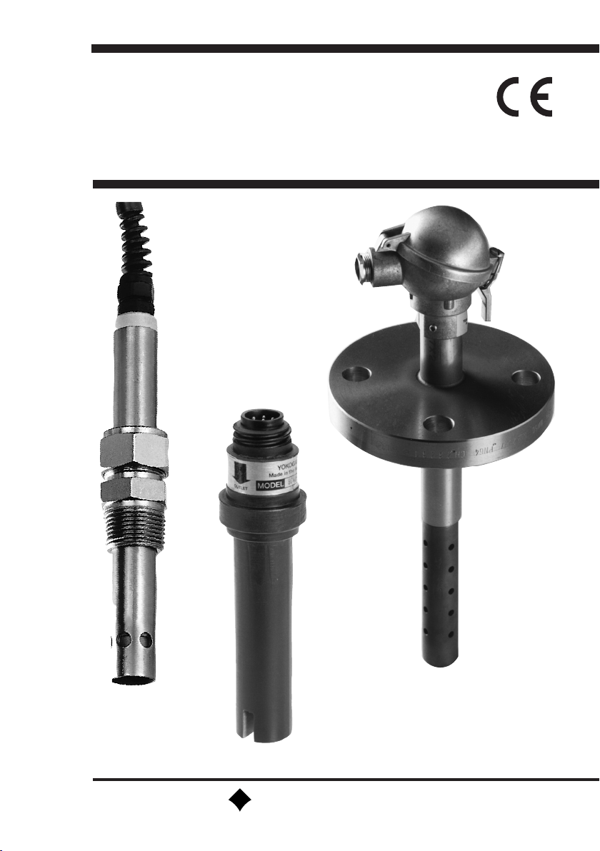
The sensor, model SC4A, SC41, SC42, SC49 and SX42, and associated fitting program is
designed to meet the most common installation requirements in terms of material compatibility,
process connections and flow dynamics. The various installation possibilities are described and
illustrated in this Instruction Manual.
Model SC4A sensors, available in a Stainless Steel or Titanium version with fixed cable or
Variopin connector, in combination with WU10/WE10-cable are intended for the low conductivity
applications. These sensors are designed in a convenient compact style, and can be inserted
directly in process pipework using available fittings or adapters.
Model SC41, SC42 and SC49 sensors, available in various materials such as Epoxy, Stainless
Steel, PTFE and PVDF, are intended to suit most process conditions. The sensors are provided
either with a Amphenol connector to fit the Yokogawa WU40 cable or Variopin connector to fit with
Yokogawa WU10/WE10-cable. A wide range of flow and immersion fittings makes it possible to
install the sensors in a permanent or semi-permanent location.
Model SX42 sensors have a Stainless Steel body and ceramic insulation, especially designed to
withstand high temperatures and high pressures. The flanged model has an integral connection box,
the threaded models are provided with a Amphenol connector to fit the Yokogawa WU40 cable or
Variopin connector to fit with Yokogawa WU10/WE10-cable.
1
All sensors have a pre-calibrated cell constant and a built-in temperature element for automatic
temperature compensation. Sensors with the Variopin connector are equipped with an ID-chip
in which callibration information is stored for easy setup when connected to a SENCOM Smart
Adapter model SA11-C1. For metal sensors a 3.1 material certificate is included. The sensors,
except those equipped with Variopin connector, are ATEX certified for installation in zone 0
environments when connected to a certified intrinsically safe Yokogawa analyser, model SC202S
or FLXA21 or a certified intrinsically safe circuit with defined output parameters (see General
Specifications of each sensor for details).
1.2 Unpacking and Checking
Upon delivery, unpack the sensor carefully and inspect it to ensure that it is not damaged during ship-
ment. If damage is found, retain the original packing material and immediately notify the carrier and the
relevant local Yokogawa Sales office. Make sure the Model Code and Serial Number on the sensor are
the same as on the packing list. Also check if option(s) that were ordered, are included and correct.
1.3 Warranty and Service
Yokogawa products are guaranteed free from defects in workmanship and materials under
normal use and service for a period of (typically) 12 months from the date of shipment from the
manufacturer. Individual Sales organizations can deviate from the typical warranty period, and the
IM 12D07J01-10E-E
Page 8
2
conditions of sale relating to the original purchase order should be consulted. Damage caused
by wear and tear, inadequate maintenance, corrosion, or by the effects of chemical processes is
excluded from this warranty coverage. In the event of a warranty claim, the defective goods should
be sent (freight paid) to the Service Department of the relevant Yokogawa Sales office for repair or
replacement (at Yokogawa’s discretion).
The following information must be included in the letter accompanying the returned goods:
• Model Code and Serial Number.
• Original Purchase Order and Date.
• Length of time in service and description of the process.
• Description of the fault and circumstances of the failure.
• Process/environmental conditions that may be related to the failure of the sensor.
• Statement as to whether warranty or nonwarranty service is requested.
• Complete shipping and billing instructions for return of material, plus the name and phone number
of a contact person that can be reached for further information.
• Clean Statement Returned goods that have been in contact with process fluids must be
decontaminated and disinfected prior to shipment. Goods should carry a certificate to this effect,
for the health and safety of our employees. Material Safety Data sheets must be included for all
components of the process to which the sensor (options) have been exposed.
1.4 Serial Number definition
The serial number is defined by nine (9) alphanumeric characters:
X1X2 Production location, N3 for Yokogawa Process Analyzers Europe B.V.
X3X4 Year/Month code
X5X6X7X8X9 Tracking number
Example: N3P600028
Method used for year/month numbering
Table 1: Production Year code Table 2: Production Month code
Year Year code Year Year code Month Month code
2014 P 2026 3 January 1
2015 R 2027 4 February 2
2016 S 2028 5 March 3
2017 T 2029 6 April 4
2018 U 2030 7 May 5
2019 V 2031 8 June 6
2020 W 2032 9 July 7
2021 X 2033 A August 8
2022 Y 2034 B September 9
2023 Z 2035 C October A
2024 1 2036 D November B
2025 2 2037 E December C
IM 12D07J01-10E-E
Page 9

2. MODEL SC4A
2.1. General Specifications
2.1.1. Measuring elements
2-electrode measuring system
Pt1000 temperature sensor
2.1.2. Materials
Wetted parts sensor:
Body & electrodes SC4A-T-AD : Titanium grade 2 or 3
SC4A-S-AD : Stainless Steel AISI 316L
SC4A-E-SA (SB, SC) : Stainless Steel AISI 316L
SC4A-T-PR : Titanium grade 2 or 3
SC4A-S-PR : Stainless Steel AISI 316L
O-ring SC4A-*-AD : Viton
SC4A-E-SA (SB, SC) : EPDM FDA approved
SC4A-*-PR : Viton
Insulation : PEEK 450G, FDA migration tested
Wetted parts adapters/fitting:
/PS, /FF SC4A-*-AD : Stainless Steel AISI 316L
/PF SC4A-*-AD : PVDF
/SA1(2), /SB1(2), /SC1 SC4A-E-SA (SB, SC) : Stainless Steel AISI 316L
3
Cable:
Versions with integrated cable only:
Conductors : tinned copper 0.6 mm
2
Outside shield : braid, tinned copper, 85% coverage
Insulator : Polyester for conductors, for colors see
Section 2.4
TPE-O for outer jacket, color black
Variopin connector:
Contacts : Gold plated
Material : Nickel plated brass
Insulation : Peek, UL94-VO
IP class : IP67
IM 12D07J01-10E-E
Page 10
4
2.1.3. Functional specifications (at 25°C)
Temperature element : Pt1000 to IEC 751
Nominal Cell Constant (C.C.) : 0.02 cm-1 or 0.1 cm
-1
Note: The SC4A temperature sensor is designed for measurement compensation and for
indication. It is NOT designed for process temperature control.
2.1.4. Dynamic specifications
Response time temperature t90 : < 1 min.
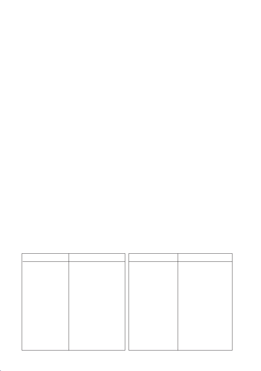
2.1.5. Operating range
Conductivity at actual process temperature : 1 µS * C.C. – 50 mS * C.C.
100 000 000.00
10 000 000.00
1 000 000.00
100 000.00
10 000.00
1 000.00
100.00
10.00
µS/cm
1.00
0.10
0.01
SC42-SP34
SX42-SX34
(0.01/cm)
SC4A-002
(0.02/cm)
SC42-SP24
SX42-SX24
(0.1/cm)
SC450/SC202/FLXA21/ FLXA202
DC402
SC4A-010
SC42-EP14
(0.1/cm)
(1/cm)
SC42EP15/EP16
(1/cm)
SC42-EP04
SC42-FP04
SC42-TP04
(10/cm)
SC450/FLXA21/
FLXA202
SC202
SC42-EP18
SC42-EP08
SC42-FP08
(1/cm)
SC42-TP04
(10/cm)
Fig. 1 Measuring range of conductivity sensors
Process temperature Stainless Steel : 0°C to 110°C (32°F to 230°F)
& Titanium type : 135°C (275°F) for a short period of time during
sterilization.
Process temperature in combination : 0°C to 80°C (32°F to 176°F)
with PVDF fitting
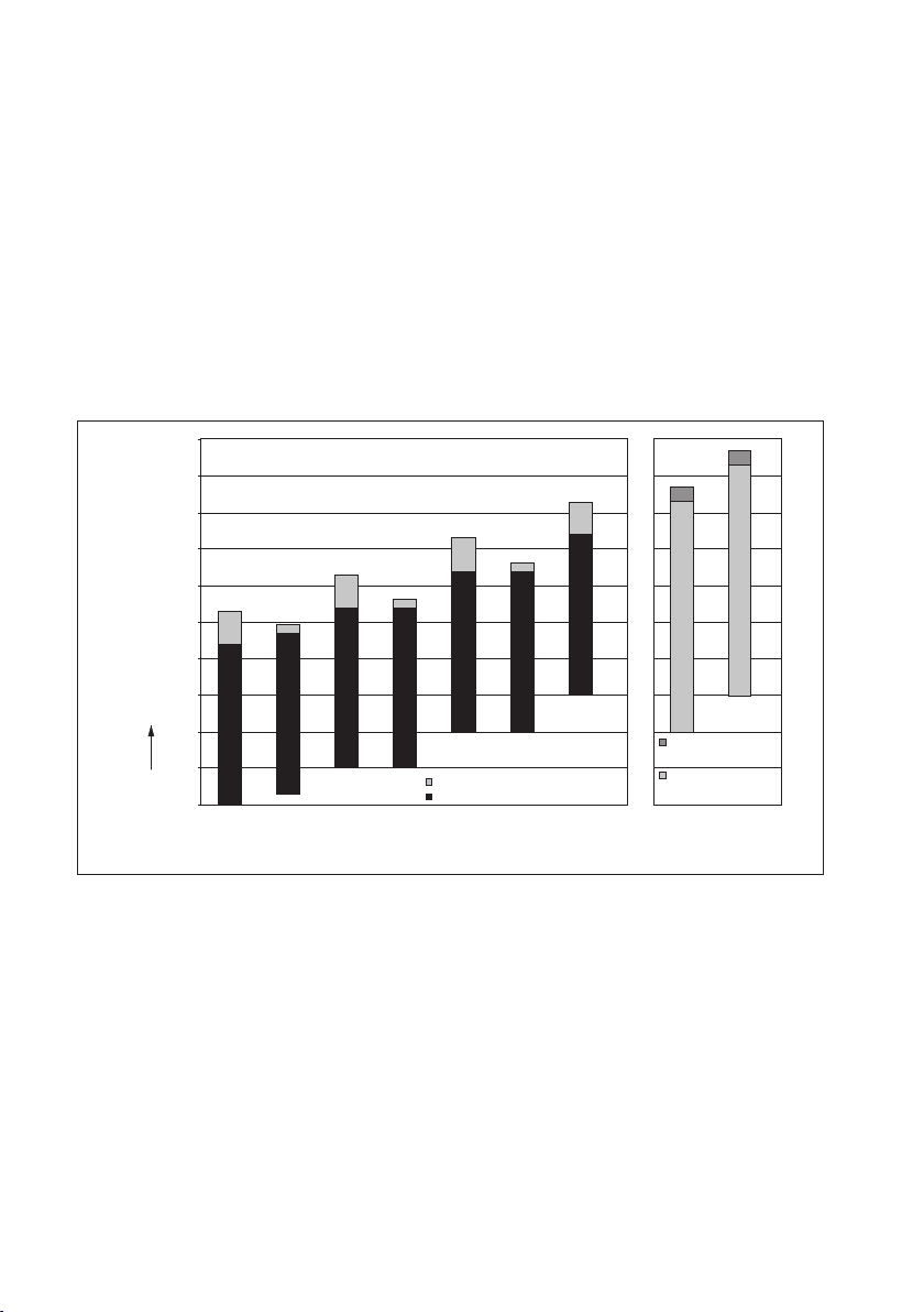
Process pressure Stainless Steel & Titanium type : 0 to 10 bar (0 to 142 PSIG)
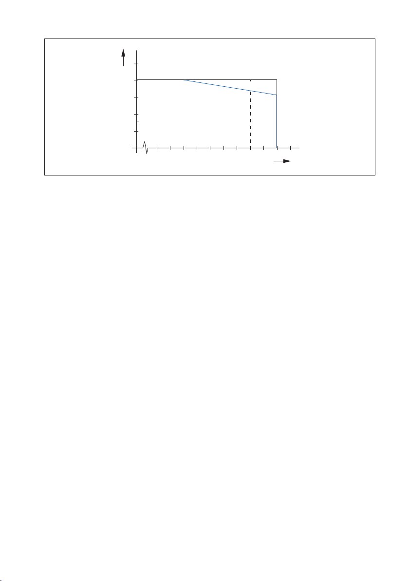
Process Pressure in combination with PVDF fitting: See Fig. 2
IM 12D07J01-10E-E
Page 11
bar
12
10
8
6
4
2
0 10 20 30 40 50 60 70 80 100 120 140 160
SS / Ti
PVDF
Fig. 2 Pressure vs temperature
Cable length for
• SC4A with fixed cable or SC4A with Variopin
directly connected to Flexa analyzer : max. 60 meter with WU10/WE10
(possibly in combination with WF10 cable
and BA10 junction box}
• For suffix -VS combined with SA11 : 3 meter WE10 cable (as option) combined
with SA11 Smart Adapter
SA11 Smart Adapter : Directly connected to the analyzer using a
WU11 cable up to 100 meters
or
Connected to a BA11 connetion box
using WU11 cable upto 100 m. The BA11
connection box is connected to the analyzer
using a WU11 cable up to 100m.
5
2.1.6. Regulatory standards (only for SC4A with fixed cable)
- ATEX : Directive 2014/34/EU
by applying:
EN 60079-0
EN 60079-11
EN 60079-26
Certificate no. : DEKRA 14ATEX0074 X
II 1 G Ex ia IIC T4… T6 Ga
IM 12D07J01-10E-E
Page 12
6
- IECEx
Applying standards : IEC 60079-0
: IEC 60079-11
: IEC 60079-26
Certificate no. : IECEx DEK 14.0032X
Ex ia IIC T4…T6 Ga
Conformity : EAC (Eurasia)
TS (Taiwan)
- Electrical data for ATEX/IECEx : For sensor input circuit connected to
A certified intrinsically safe circuit with the following
maximum values:
Ui = 14.4 V; Ii = 116.5 mA; Pi = 0.342 W
or
Certified intrinsically safe Yokogawa Contact
Conductivity transmitter Model FLXA21 series or
Model SC202S series.
The effective internal capacitance Ci and the
effective internal inductance Li of the sensor depends only
upon the properties and length of the integral cable.
Special conditions (X) : T6 for Tamb. -30°C to 40°C
T5 for Tamb. -30°C to 95°C
T4 for Tamb. -30°C to 130°C
Impact on the product shall be avoided.
Electrostatic charges on the enclosure shall be avoided.
From the safety point of view the circuits shall be
assumed to be connected to earth.
Regulatory standards (all types)
CE : Decision 768/2008/EC
- Pressure : Directive 2014/68/EU
Applying article : 4.3 (Sound Engineering Practice)
- RoHS2 : Directive 2011/65/EU
Applying category : 9 (Industrial monitoring and control instruments)
IM 12D07J01-10E-E
Page 13

2.1.7. Shipping details
Package size (LxWxH) : 220 x 220 x 90 mm (8.7 x 8.7 x 3.6 inch)
Package weight : 0.5 to 1.7 kg (1.1 to 3.8 lbs), depends on sensor type
and cable length
2.1.8. Environmental conditions
Storage temperature : -30°C to 50°C (-22°F to 122°F)
2.1.9. Mechanical specifications
Surface roughness SC4A-*-AD : 0.8 µm
SC4A-E-SA (SB, SC) : 0.5 µm
SC4A-*-PR : 0.8 µm
2.2. Installation of SC4A sensors
For optimum measurement results, the SC4A sensor should be installed in a location that
offers an acceptable representation of the process composition and DOES NOT exceed the
specifications of the sensor.
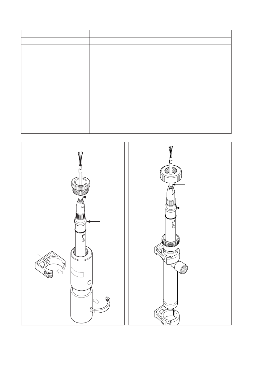
2.2.1. Typical installation SC4A-*-AD with standard options
The SC4A-*-AD sensor can be installed in the process using optional ¾” NPT adapters. These
adapters are available in Stainless Steel (/PS) and in PVDF (/PF); see figure 3 for the mounting
sequence. The sensor can also be installed in an optional Stainless Steel flow fitting (/FF) using
option /PS, see figure 4 for details.
3/4 “NPT
1/4 “NPT
7
Fig. 3 Mounted sensor
with the option /PF and /PS
100 (3.94”)
1/4 “NPT
30(1.18”)
Fig. 4 Dimensional drawing /FF
with the option /PS
IM 12D07J01-10E-E
Page 14

8
2.2.2. Typical installation SC4A-E-SA (SB, SC) with standard options / spare parts
The typical installation of the SC4A-E-SA sensor is done by using a standardized 25 mm port.
Stainless Steel welding sockets are available as straight version (spare part /SA1) or 15° angled
version (spare part /SA2). Both versions are delivered with mounting nut.
In figure 5 an example is shown how to install the sensor using spare part /SA1.
Sensors SC4A-E-SB and SC4A-E-SC are installed by tri-clamp method.
For the SB version two Stainless Steel tri-clamps are available, in a 1” size
(spare part /SB1) or in a 1½“ size (spare part /SB2).
The SC version has just one Stainless Steel tri-clamp in a 2” size (spare part /SC1).
/SA1
51 (2.00")
55 (2.16")
Fig 5. Mounted SC4A-E-SA sensor
with sparepart/ SA1
IM 12D07J01-10E-E
Fig 6 Mounted SC4A-E-SB sensor
Page 15

Ø 19,1
(0.75")
90 (3.55")
Ø 25
(1.00")
Ø 38 x 5
(1.50 x 0.20)
95 (3.74")
25
(1.00”)
M19x1.5
48 (1.89")
19.8
Ø 24.9
Ø 19.1
152 (5.98")
152 (5.98")
95 (3.74")
41
52
Ø
27.5
Ø 19.1
M19x1.5
48 (1.89")
41
52
Ø
27.5
Ø 19.1
Ø 19,1
(0.75")
90 (3.55")
Ø 25
(1.00")
Ø 38 x 5
(1.50 x 0.20)
95 (3.74")
25
(1.00”)
Ø50,4
(1.98")
Ø19
(0.75")
1 - 1.5 "
tri-clamp
2 "
tri-clamp
Ø25
(1.00")
80 (3.15")
Ø63,9
(2.52")
M19x1.5
48 (1.89")
19.8
Ø 24.9
Ø 19.1
152 (5.98")
152 (5.98")
95 (3.74")
70 (2.75")
41
52
Ø
27.5
Ø 19.1
Ø 64
Ø 25
Ø 50.5
Ø 19.1
Ø 19.1
2 "
tri-clover
1" - 1
1
/2"
tri-clover
70
80
M19x1.5
48 (1.89")
19.8
Ø 24.9
Ø 19.1
95 (3.74")
41
52
Ø
27.5
Ø 19.1
Ø 64
Ø 25
Ø 50.5
Ø 19.1
Ø 19.1
2 "
tri-clover
1" - 1
1
/2"
tri-clover
70
80
2.2.3. Typical installation SC4A-*-PR
The installation of the SC4A-*-PR sensor is done using the Model PR10 retractable fitting.
The mounting procedure of the sensor is explained in the Instruction Manual of this fitting.
2.3. Dimensions SC4A sensors
units in mm (inch)
Fig 7. SC4A-AD Fig. 8. SC4A-SA Fig. 9. SC4A-PR
9
Fig. 10 : Dimensions of SC4A-SB/SC sensor
IM 12D07J01-10E-E
Page 16

10
2.4. Wiring SC4A sensors
The SC4A sensors are provided with a fixed sensor cable or Variopin connector to fit the WU10/WE10
cable up to 20 meters. When a longer cable run is necessary (maximum cable run is 60 meters), this
can be done by using the WF10 extension cable in combination with the BA10 connection box. The
connection of the integral cable and WF10 cable to the Yokogawa Contact Conductivity analyser are
given in table 3.
Table 3. Definition fixed sensor cable, WF10 cable and analyser
Cable wire color Cable wire color WF10 SC terminal # Signal description
White Red 11 Temperature
Brown Blue 12 Temperature
Green Clear (Core of Brown coax) 13 Inner electrode
Yellow Yellow 14 Outer electrode
Black Clear (Core of White coax) 15 Inner electrode
Pink White (Shield of White coax) 16 Outer electrode
Table 4. Definition VP sensor cable, WU10/WE10 cable and analyser
WU10/WE10 Color SC
A Core brown Ui
B Shield brown Ii
C Core white Uo
D Shield white Io
E Red T1
F Blue T2
G Yellow VCC ID chip
H Green Data ID chip
Drain wire Black Shield
Note: Sensors with Variopin contain an embedded ID chip which is recognized to work with
SA11 Smart Adapter model SA11-C1
Note: WU10-V-D type
IM 12D07J01-10E-E
Page 17

2.5. Modelcode SC4A sensors
Model Suffix Code Option code Description
SC4A 19 mm conductivity sensor
material -T Titanium Grade 2 or 3
-S Stainless steel AISI 316L (SS)
-E EPDM FDA
fitting-type -AD For adapter mounting
-PR For retractable mounting
-SA For sanitary purposes
-SB 1-1½” tri-clamp
-SC 2” tri-clamp
sensor-length -09 9 cm
1)
-15 15 cm
-NN Fixed length
cellconstant -002 0.02/cm
-010 0.1/cm
connection type -03 Fixed cable with wirepins, 3 m
-05 Fixed cable with wirepins, 5 m
-10 Fixed cable with wirepins, 10 m
-15 Fixed cable with wirepins, 15 m
-20 Fixed cable with wirepins, 20 m
-VS No Cable; Variopin connector
with SENCOM ID-chip
2)
-T1 Pt1000
/PS 3/4” stainless steel adapter
/PF 3/4” PVDF adapter
/FF Flow fitting stainless steel AISI 316L
11
3)
Note 1: Suffix -AD-09 not available with -VS.
Note 2: Suffix -VS not ATEX/IECEx certified.
Note 3: With option /FF: option /PS is mandatory.
IM 12D07J01-10E-E
Page 18

12
2.6. Spare parts SC4A
Adapters SC4A-*-AD sensor
Part no. Description Process connection Material Quantity
K1542DF /PS 3/4” NPT adapter Stainless Steel 1
K1542CW /PF 3/4” NPT adapter PVDF 1
K1598AC /FF Flow fitting Stainless Steel 1
Adapters SC4A-E-SA sensor
Part no. Description Process connection Material Quantity
K1542FA /SA1 Straight welding socket Stainless steel 1
K1542FB /SA2 Angled welding socket Stainless steel 1
Spare parts for adapters SC4A-E-SA sensor
Part no. Description Quantity
K1520EJ Straight weld-in adapter without mounting nut, Stainless Steel 1
K1520EK Angled weld-in adapter without mounting nut, Stainless Steel 1
Spare parts for SC4A-E-SA sensor
Part no. Description Quantity
K1542DL O-ring set, EPDM FDA, 20.3 x 2.62 3
K1542DK O-ring set, Viton, 20.3 x 2.62 3
Adapters SC4A-E-SB sensor
Part no. Description Process connection Material Quantity
K1542FC /SB1 Tri-clamp 1” Stainless Steel 1
K1542FF /SB2 Tri-clamp 1½“ Stainless Steel 1
Spare parts for adapters SC4A-E-SB sensor
Part no. Description Quantity
K1500BN Clamp seal ring, EPDM FDA, 1” ~ 1½“ 1
K1542DG Clamp seal ring, Viton, 1“ 3
K1542DH Clamp seal ring, Viton, 1½“ 3
Adapters SC4A-E-SC sensor
Part no. Description Process connection Material Quantity
K1542FE /SC1 Tri-clamp 2” Stainless Steel 1
Spare parts for adapters SC4A-E-SC sensor
Part no. Description Quantity
K1500BP Clamp seal ring, EPDM FDA, 2“ 1
K1542DJ Clamp seal ring, Viton, 2“ 3
Spare parts for SC4A-*-PR sensor
Part no. Description Quantity
K1500BE O-ring set, Viton, 15.6 x 1.78 10
K1500ED O-ring set, Kalrez, 15.6 x 1.78 1
IM 12D07J01-10E-E
Page 19

3. MODEL SC41, SC42 AND SC49
3.1. General Specifications
3.1.1. Measuring elements
2-electrode for SC41/SC42-SP series; SC41/SC42-EP04 (EP14); SC41/SC42-EP15 (EP16) series
4-electrode for SC42/SC49-EP08 (EP18); SC42/SC49-FP08 (TP08)
Pt1000 temperature sensor
3.1.2. Materials
Wetted parts sensor:
Body SC41/SC42/SC49-SP/SV : Stainless Steel AISI 316L
SC41/SC42/SC49-EP : Glass filled epoxy resin
SC41/SC42/SC49-FP/FV : PVDF, Glass
SC41/SC42/SC49-TP/TV : Glass filled PTFE, Glass
Electrodes SC41/SC42/SC49-SP/SV : Stainless Steel AISI 316L
SC41/SC42/SC49-EP : Graphite impregnated with epoxy resin
SC41/SC42/SC49-FP/FV : Platinum
SC41/SC42/SC49-TP/TV : Platinum
O-ring SC41/SC42/SC49-SP/SV : Viton
SC41/SC42/SC49-FP/FV : Viton
SC41/SC42/SC49-TP/TV : Kalrez™
13
For the -FP/FV and -TP/TV the supplied O-ring for sealing in the fitting is Viton.
Insulation -SP/SV : PEEK 450G, FDA migration tested
Connector:
Amphenol: Contacts : gold plated
Plug : Polyamide
Variopin: Contacts : gold plated
Material : Nickel-plated brass
Insulation : PEEK, UL94-V0
IP class : IP67
IM 12D07J01-10E-E
Page 20

14
3.1.3. Functional specifications (at 25°C)
Temperature element SC41, SC49 : Ni100
Temperature element SC42 : Pt1000 to IEC 751
Nominal Cell Constant SC41/SC42/SC49-SP/SV24 : 0.1 cm
SC41/SC42/SC49-SP/SV34 : 0.01 cm
SC41/SC42/SC49 (EP08) : 10 cm
SC41/SC42/SC49-EP14 (EP18) : 1 cm
SC41/SC42/SC49-EP15 (EP16) : 1 cm
SC41/SC42/SC49-FP/FV : 10 cm
SC41/SC42/SC49-TP/TV : 10 cm
-1
-1
-1
-1
-1
-1
-1
Note: The SC41/SC42/SC49 temperature sensor is designed for measurement compensation
and for indication. It is NOT designed for process temperature control.
3.1.4. Dynamic specifications
Response time temperature t90
SC41/SC42/SC49-SP/SV24 : < 3 min.
SC41/SC42/SC49-SP/SV34 : < 1 min.
SC41/SC42/SC49-EP04 (EP08) : < 3 min.
SC41/SC42/SC49-EP14 (EP18) : < 2 min.
SC41/SC42/SC49-EP15 (EP16) : < 3 min.
SC41/SC42/SC49-FP/FV : < 1 min.
SC41/SC42/SC49-TP/TV : < 1 min.
3.1.5. Operating range
Conductivity at actual process temperature : 1 µS * C.C. – 200 mS * C.C.
See Fig. 2: Measuring range of conductivity sensors section 2.1.5
Temperature SC41/SC42/SC49-SP/SV : 0°C to 150°C (32°F to 302°F)
SC41/SC42/SC49-EP : 0°C to 110°C (32°F to 230°F)
SC41/SC42/SC49-FP/FV : 0°C to 110°C (32°F to 230°F)
SC41/SC42/SC49-TP/TV : 0°C to 110°C (32°F to 230°F)
Pressure SC41/SC42/SC49-SP/SV : 0 to 10 bar (0 to 142 PSIG)
SC41/SC42/SC49-EP : 0 to 10 bar (0 to 142 PSIG)
SC41/SC42/SC49-FP/FV : 0 to 10 bar (0 to 142 PSIG)
SC41/SC42/SC49-TP/TV : 0 to 2 bar (0 to 28 PSIG)
Cable length for
Sensors with Amphenol connector or
Variopin connector directly connected
to Flexa analyzer : max. 60 meter with WU10 or WU10 in
combination with WF10 cable and BA10
junction box
For sensors with suffix -VS combined with SA11 : Optional 3 meter WE10 cable combined with
SA11 Smart Adapter
IM 12D07J01-10E-E
Page 21

SA11 Smart Adapter : Directly connected to the analyzer using a
WU11 cable up to 100 meters
or
Connected to a BA11 connetion box
using WU11 cable upto 100 m. The BA11
connection box is connected to the analyzer
using a WU11 cable up to 100m
3.1.6. Regulatory standards (only for SC42 with Amphenol connector)
- ATEX : Directive 2014/34/EU
by applying:
EN 60079-0
EN 60079-11
EN 60079-26
Certificate no. : DEKRA 14ATEX0074 X
II 1 G Ex ia IIC T4… T6 Ga
- IECEx
Applying standards : IEC 60079-0
: IEC 60079-11
: IEC 60079-26
Certificate no. : IECEx DEK 14.0032X
Ex ia IIC T4…T6 Ga
Conformity : EAC (Eurasia)
TS (Taiwan)
15
- Electrical data for ATEX/IECEx : For sensor input circuit connected to
A certified intrinsically safe circuit with the following
maximum values:
Ui = 14.4 V; Ii = 116.5 mA; Pi = 0.342 W
or
Certified intrinsically safe Yokogawa Contact
Conductivity transmitter Model FLXA21 series or
Model SC202S series.
The effective internal capacitance Ci and the
effective internal inductance Li of the sensor depends only
upon the properties and length of the integral cable.
Special conditions (X) : T6 for Tamb. -30°C to 40°C
T5 for Tamb. -30°C to 95°C
T4 for Tamb. -30°C to 130°C
IM 12D07J01-10E-E
Page 22

16
Impact on the product shall be avoided.
Electrostatic charges on the enclosure shall be avoided.
From the safety point of view the circuits shall be
assumed to be connected to earth.
Regulatory standards (all types)
CE : Decision 768/2008/EC
- Pressure : Directive 2014/68/EU
Applying article : 4.3 (Sound Engineering Practice)
- RoHS2 : Directive 2011/65/EU
Applying category : 9 (Industrial monitoring and control instruments)
3.1.7. Shipping details
Package size (LxWxH) : 300 x 95 x 73 mm (11.8 x 3.7 x 2.9 inch)
Package weight : 0.3 to 0.8 kg (0.7 to 1.8 lbs), depends on
sensor type
3.1.8. Environmental conditions
Storage temperature : -30°C to 50°C (-22°F to 122°F)
bar
12
10
8
6
4
2
0 10 20 30 40 50 60 70 80 100 120 140 160
Fig. 11 Pressure vs temperature
IM 12D07J01-10E-E
FP/FV
TP/TV
EP
SP/SV
Page 23

17
3.2. Installation of SC41/SC42/SC49 sensors
To install the SC41/SC42/SC49 conductivity sensors in a permanent or semi-permanent location,
Yokogawa can supply a range of flow and immersion fittings. These fittings and sub-assemblies are
available in different materials to give the best solution for any process considering chemical resistance,
pressure and temperature specifications (see figure 11). Flow fittings are available with optional flange
adapters. When installing the SC41/SC42/SC49 sensor in a fitting, an O-ring is necessary. This O-ring is
available in different materials to improve chemical resistance (see Section 3.6 for ordering information).
If the SC41/SC42/SC49 sensor is supllied with an O-ring, the O-ring in the fitting must be
removed.
3.2.1. Typical installation of SC41/SC42/SC49 sensor in FF40 Flow fittings/ FS40 Flow
fitting assemblies
From a practical point of view, the best mounting place for a conductivity sensor is in a by-pass
with a sample valve. For these applications the following Flow fittings/Flow fitting subassemblies
are ideal: Model FF40: Flow fitting
Model FS40: Flow fitting subassembly
When using the sensor in combination with a Flow fitting or Flow fitting subassembly, the process
flow has to be taken into account when mounting the sensor. For an example see figure 12
Reasonable
Bad
Fig. 12 Mounting position SC41/SC42/SC49 sensor
Bad
Good
Good
IM 12D07J01-10E-E
Page 24
18
Modelcode FF40 Flowfitting:
Model code Suffix code Option code Description
FF40 Flow fitting
Material - P22 Polypropylene (PP)
- S22 Stainless steel (AISI 316)
- V22 Polyvinylchloride (PVC)
Optional Flange adapters /FP1 DN15 PN10 PP
(NPT ½” Male lap joint) /FP2 DN25 PN10 PP
/FP3 ½” ANSI 150 lbs PP
/FP4 1” ANSI 150 lbs PP
/FS1 DN15 PN10 SS AISI 316
/FS2 DN25 PN10 SS AISI 316
/FS3 ½” ANSI 150 lbs SS AISI 316
/FS4 1” ANSI 150 lbs AISI 316
Material Certificate /M 3.1 according to EN-10024 on wetted parts
Sensor cable
Sensor cable
Plug-in
sensor
Plug-in
sensor
M8 thread
Fig. 13 Installation SC41/SC42/SC49
Fig. 14 Installation SC41/SC42/SC49
in FF40-P22/FF40-V22 *)
Note: Not possible for sensors with suffix code -EP16
IM 12D07J01-10E-E
in FF40-S22 *)
Page 25

Ø 35
(1.38)
Ø 54 (2.76)
32
(1.26)
IN
Ø 40 (1.57)
120 (4.72)
(adj.)
153 (6.0)
231 (9.09)
OUT
Units in mm (inch)
19
Ø 60
(Ø 2.36)
245 (9.65)
125 (4.92)
FLOW Direction IN
Ø 12
87 (3.42)
OUT
231 (9.09)
(adj.)
120 (4.72)
IN
Ø 40 (1.57)
32
(1.26)
Ø 35
(1.38)
Ø 54 (2.76)
OUT
153 (6.0)
Fig. 15 Dimensions FF40-P22 (V22) Fig. 16 Dimensions FF40-S22
Flange adapters are available for the FF40-P22 (option /FP*) and for the FF40-S22 (option /FS*)
D
ø 115
ø 85
4x 13.5
ø 16
k
dg
1
/2Inch 1 Inch
ø 88.9
ø 108
ø 60.5
ø 79.2
ø 15.7
ø 15.7
ø 11.2
ø 17.5
b
231
Ø 54
OUT
32
Ø 36
L1
DN15 DN25
D
ø 95
k
ø 65
dg
4x 13.5
B
ø 11.5
L2
IN
Type DN15PN10 DN25-PN10 1/2” 150 lbs 1” 150 lbs
L1 L2 L1 L2 L1 L2 L1 L2
FF40-S22 226 123 236 133 8 7/8” 4 13/16” 9 5/16” 5 1/4”
FF40-P22 247 123 236 112 9 3/4” 4 7/8” 9 5/16” 4 7/16”
Fig. 17 Dimensions of optional Flange adapters
IM 12D07J01-10E-E
Page 26

20
Modelcode FS40 Subassembly for Flow fitting
Model code Suffix code Option code Description
FS40 Subassembly for Flow fitting
Material - F22 Polyvinylidenefluoride (PVDF)
- S22 Stainless steel (AISI 316)
- S23 Stainless steel (AISI 316) for EP16 model sensor
- V22 Polyvinylchloride (PVC)
Mounting - WE Weld-in socket for - S22 and - S23
Glue-in socket for - V22
- PA Parallel thread, only for - F22, (ISO 228/1-G11/4”)
- TP Tapered pipe thread (11/4” NPT)
- DF For insertion type sensor with collar piece
DN25 in combination with - S23
Material Certificate /M 3.1 according to EN-10024 on wetted parts
Sensor
(EP16 model)
FS40-S23-DF
Fig. 18 Installation example of the SC41/SC42/-EP16 sensor
with a FS40-S23-DF subassembly
IM 12D07J01-10E-E
Page 27

21
24 (0.95)
27 (1.06)
36 (1.42)
27 (1.06)
52 (2.05)
19 (0.75)
FS40-S23-DF
FS40-S22-WE
FS40-F22-PA
Ø 63
(2.48)
Ø 31
(1.22)
Ø 28
(1.10)
Ø 54
(2.12)
Ø 38
(1.50)
Ø 36
(1.42)
Ø 55
(2.16)
1 1/4" ISO
228/1-G 1
1/4
36 (1.42)
61 (2.40)
50 (1.97)
41 (1.61)
32 (1.26)
57 (2.25)
27 (1.06)
FS40-F22-TP
FS40-V22-TP
FS40-S22-TP
24 (0.95)
FS40-V22-WE
Ø 55
(2.16)
1 1/4"-11.5
NPT
Ø 54
(2.12)
1 1/4" NPT
Ø 50
(1.97)
Ø 40
(1.57)
Fig. 19 Dimensions FS40 Flow fitting subassemblies
IM 12D07J01-10E-E
Page 28

22
3.2.2. Typical installation of SC41/SC42/SC49 sensor in FD40 Immersion fitting
The immersion fittings are for installing the SC41/SC42/SC49 sensor in tanks, open vessels or drains.
If the fitting is mounted in a tank with agitator or if it is placed in a fast flowing process, care must be
taken that the fitting is adequately supported. For this reason mounting several flanges can be ordered.
Modelcode FD40 FD40 Immersion fitting
Model code Suffix code Option code Description
FD40V28 Immersion fitting PVC
FD40S28 Immersion fitting Stainless Steel AISI 316
Immersion - Between 05 and 20 decimeter
depth (Example 06 = 6 dm. = 0.6 m.)
- NC
Flange - FN No flange
- F1 PVC flange DN50 PN10
- F2 PVC flange ANSI 2” 150 lbs
- F3 Stainless Steel flange DN50 PN10
- F4 Stainless Steel flange ANSI 2” 150 lbs
Style code * B
Protection hose /PH5 For 5.5 meter mounting cable
/PH10 For 10 meter mounting cable
Mounting cable /C05 Length 5,5 meter*
/C10 Length 10 meter*
Material Certificate /M 3.1 according to EN-10024 on SS wetted parts
Note: If it is necessary to use the fitting with another mounting cable length, this cable can be
ordered separately as WU40 model (Amphenol connector) or WU10/WE10 (Variopin
connector). This is not applicable for sensors with suffix V (Variopin model).
Model code Suffix code Description
WU40 Sensor cable
Cable length - LH01 1 meter
- LH02 2 meters
- LH05 5½ meters
- LH10 10 meters
- LH15 15 meters
- LH20 20 meters
- LH25 25 meters
IM 12D07J01-10E-E
Model code Suffix code Description
WU10 Universal sensor
cable
Conn. type -V Variopin
Cable type -D Dual Coax
Cable length -02 2 meters
-05 5 meters
-10 10 meters
-15 15 meters
-20 20 meters
Page 29

3.3 Dimensions SC41/SC42/SC49 sensors.
SC4 -SP34 (L=164 mm)
SC4 -SP24 (L=111 mm)
SC4 -SV34 (L=164 mm)
SC4 -SV24 (L=111 mm)
23
4.37
111
2.24
0.47
12
0.39
10
57
30
1.18
*
*
0.47
6.46
- * = Minimum submersion depth.
- Dimensions in millimeters [Inches].
5.67
144
164
7.76
197
12
7.19
182.6
9.28
235.6
ø 36
20
10
56
L
12
ø 30
Fig. 20 Dimensions SC4 -SP Fig. 21 Dimensions SC4 -SV
30
1.18
2.24
0.39
57
10
30
1.18
IM 12D07J01-10E-E
Page 30

24
12D7J1-15
INSERTION SENSORS
SC4.-EP15
12D7J1-16
INSERTION SENSORS
SC4.-EP15D
SC4 -FP08
SC4 -TP08
ø 36
(1.42")
46
(1.81")
30
(1.18")
ø 29
(1.14")
26
(1.02")
ø 5
(0.20")
SC4 -FV08
SC4 -TV08
20
(0.78")
10
(0.40")
194
SC42-FV08
SC42-TV08
1.18
30
0.39
10
1.14
1.18
30
8.94
227
7.64
194
29
1.8
46
1.16
29
*
1.02
26
- * = Minimum submersion depth.
- Dimensions in millimeters [Inches].
10.46
266
Fig. 22 Dimensions SC4 -FP/TP
20
10
100
ø 36
ø 25
15
Fig. 23 Dimensions SC4 -FV/TV
20
10
65
ø 44
ø 25
15
Fig. 24 SC41/SC42-EP15 Fig. 25 SC41/SC42-EP16
IM 12D07J01-10E-E
20
(0.78")
ø 36
(1.42")
ø 30
(1.18")
43
(1.69")
30
(1.18")
10
(0.40")
L
ø d
SC4 -EP04 (L= 193 mm)
SC4 -EP14 (L= 160 mm)
SC4 -EP08 (L= 193 mm)
SC4 -EP18 (L= 160 mm)
Fig. 26 SC4 -EP14 (EP18),
SC4 -EP04 (EP08)
Page 31

3.4. Wiring SC41/SC42/SC49 sensors
The SC41, SC42 and SC49 sensors are provided with a fixed connector. The standard cable
used to connect the sensor with Amphenol connector to the analyser is the WU40. The standard
cable used to connect the sensor with VP connector to the analyzer is the WU10. These cables
are available up to 25/20 meters. When a longer cable run is necessary (maximum cable run
is 60 meters), this can be done by using the WF10 extension cable in combination with the
BA10 connection box. The connection of the WU40 cable, WU10 cable and WF10 cable to the
Yokogawa Contact Conductivity analyser are given in table 4.
11
CELL
16
12
15
13
temp.
14
element
Amphenol
connector
CELL
11
16
12
15
13
temp.
14
element
Amphenol
connector
25
Variopin
connector
Fig. 27 Top view connector system SC41/
SC42 2-electrode
Variopin
connector
Fig. 28 Top view connector system SC42/
SC49 4-electrode
3.5 Modelcode SC41/SC42/SC49
Model Suffix Code Option code Description
SC41 (SC49) Conductivity Sensor 2- or 4- electrodes + Ni100
SC42 Conductivity Sensor 2- or 4- electrodes + Pt1000
Materials -E Epoxy / graphite
-S Stainless steel AISI 316L / PEEK
-F PVDF / Glass / Platinum
-T PTFE / Glass / Platinum
Mounting P Plug-in type, plug-socket connector
V1) Plug-in type, VarioPin connector with SENCOM
ID-chip 1)
Cell constant 0 Cell constant
1 C = 1 cm-1
2 C = 0,1 cm-1
3 C = 0,01 cm-1
Type 4 2-electrode, flow cell
5 2-electrode, insertion cell
6 2-electrode, insertion cell with DN25 collar
8 4-electrode, flow cell
Options N/A
Note: Suffix V not ATEX/IECEx certified. Suffix V not in combination with suffix -E (Epoxy).
IM 12D07J01-10E-E
Page 32

26
4. MODEL SX42
4.1. General Specifications
4.1.1. Measuring elements
2-electrode measuring system
Pt1000 temperature sensor
4.1.2. Materials
Wetted parts sensor:
Body : Stainless Steel AISI 316L
Electrodes : Stainless Steel AISI 316L
Insulation : Ceramic (aluminium oxide)
Connector:
Amphenol: Contacts : gold plated
Plug : Polyamide
Variopin: Contacts : gold plated
Material : Nickel-plated brass
Insulation : PEEK, UL94-V0
IP class : IP67
Terminal box flanged models:
Housing : Aluminium
Insulation : Ceramic
4.1.3. Functional specifications (at 25°C)
Temperature element : Pt1000 to IEC 751
Nominal Cell Constant (C.C.) SX42-SX24 : 0.1 cm
SX42-SX34 : 0.01 cm
-1
-1
Note: The SX42 temperature sensor is designed for cell compensation and for indication.
It is NOT designed for process temperature control.
4.1.4. Operating range
Conductivity at actual process temperature : 1 μS * C.C. – 200 mS * C.C.
See Fig. 2: Measuring range of conductivity
sensors section 2.1.5
Temperature Threaded models (-BS,-NS) : 0°C to 200°C (32°F to 392°F)
Threaded models (-BV,-NV) : 0°C to 125°C (32°F to 257°F)
Flanged models : 0°C to 250°C (32°F to 482°F)
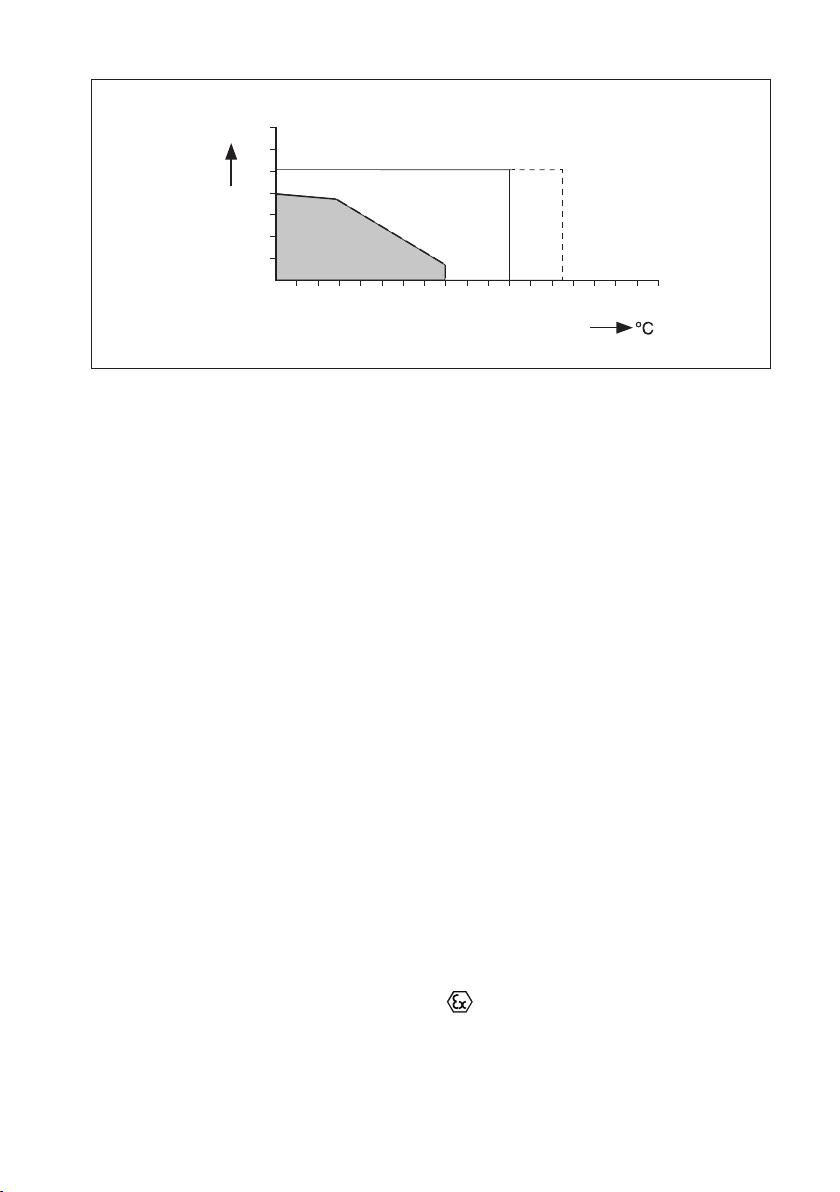
Pressure Threaded models : 0 to 40 bar (0 to 363 PSIG)
Flanged model PN63 : 0 to 40 bar (0 to 580 PSIG)
Flanged model PN40 : 0 to 30 bar (0 to 435 PSIG)
IM 12D07J01-10E-E
Page 33
27
ºC
50
bar
40
30
25
20
16
10
0
0
50 100 150 200 250
Flange PN63
Flange PN40
dedaerhT
Fig. 29 Pressure vs. process temperature flanged / threaded models SX42
Cable length:
Threaded models (-BS,-NS) : max. 60 meter with WU40 cable in combination
with WF10 cable and BA10 junction box
Threaded models (-BV,-NV)
Variopin connector directly connected : max. 60 meter with WU10/WE10
(possibly in combination with WF10 cable
and BA10 junction box}
For sensors with suffix -BV/NV : 3 meter WE10 cable (as option) combined
with SA11 Smart Adapter
combined with SA11 Smart Adapter Smart Adapter directly connected to the
analyzer using a WU11 cable up to 100 meters
or
Connected to a BA11 connetion box
using WU11 cable upto 100 m. The BA11
connection box is connected to the analyzer
using a WU11 cable up to 100m
Flanged models : max. 60 meter with customer specified high
temperature cable
IM 12D07J01-10E-E
Page 34

28
4.1.5. Regulatory standards (not applicable for sensors with suffix code -BV or -NV)
- ATEX : Directive 2014/34/EU
by applying:
EN 60079-0
EN 60079-11
EN 60079-26
Certificate no. : DEKRA 14ATEX0074 X
II 1 G Ex ia IIC T4… T6 Ga
- IECEx
Applying standards : IEC 60079-0
: IEC 60079-11
: IEC 60079-26
Certificate no. : IECEx DEK 14.0032X
Ex ia IIC T4…T6 Ga
Conformity : EAC (Eurasia)
TS (Taiwan)
- Electrical data for ATEX/IECEx : For sensor input circuit connected to
A certified intrinsically safe circuit with the following
maximum values:
Ui = 14.4 V; Ii = 116.5 mA; Pi = 0.342 W
or
Certified intrinsically safe Yokogawa Contact
Conductivity transmitter Model FLXA21 series or
Model SC202S series.
The effective internal capacitance Ci and the
effective internal inductance Li of the sensor depends only
upon the properties and length of the integral cable.
Special conditions (X) : T6 for Tamb. -30°C to 40°C
T5 for Tamb. -30°C to 95°C
T4 for Tamb. -30°C to 130°C
Impact on the product shall be avoided.
Electrostatic charges on the enclosure shall be avoided.
From the safety point of view the circuits shall be
assumed to be connected to earth.
Regulatory standards (all types)
CE : Decision 768/2008/EC
- Pressure : Directive 2014/68/EU
Applying article : 4.3 (Sound Engineering Practice)
- RoHS2 : Directive 2011/65/EU
Applying category : 9 (Industrial monitoring and control instruments).
IM 12D07J01-10E-E
Page 35

4.1.6. Shipping details
SX42-SX24-BS
SX42-SX24-NS
SX42-SX24-DF
SX42-SX24-AF
SX42-SX34-DF
SX42-SX34-AF
SX42-SX34-BS
SX42-SX34-NS
225 (10.04)
ø 28 (1.10)
ø 28 (1.10)
91 (3.58) 110 (4.33)
98 (3.86)
164 (6.42) 91 (3.58)
150 (5.90)
35 (1.38)
ø 34
(1.34)
23 (0.90)
169 (6.65)
110 (4.33)
169 (6.65)
ø 34
(1.34)
3.78
96 *
0.83
21 *
282
1.1
243
9.57
138
5.43
28
11.09
T
h
r
e
a
d
t
yp
e
7.48
190
28
1.1
229
3.35
85
9
T
h
r
e
a
d
t
yp
e
SX42-SX34-BV
SX42-SX34-NV
SX42-SX34-BV
SX42-SX34-NV
8X
Package size (LxWxH) Threaded models : 300 x 95 x 73 mm (11.8 x 3.7 x 2.9 inch)
Flanged models : 480 x 275 x 235 mm (18.9 x 10.8 x 9.3 inch)
Package weight Threaded models : 0.5 to 0.7 kg (1.1 to 1.5 lbs)
Flanged models : 5.7 to 6.0 kg (12.6 to 13.2 lbs)
4.1.7. Environmental conditions
Storage temperature : -30°C to 50°C (-22°F to 122°F)
4.2. Installation of SX42 sensors
SX42 threaded models are installed by screw-in (ISO 7/1-R 1” or 1” NPT), and the SX42 flanged
models by using the pre-mounted flange (DN50 PN63, DN50 PN40 or ANSI 2” 600 lbs).
Flange dimensions of DN50 PN40 (in red) to be included
ANSI 2”600LBS
ø 165 (6.5)
ø 127 (5.0)
ø 91.9 (3.62)
ø 19.1 (0.75)
20
(0.79)
DN50 PN40
ø 165 (6.5)
ø 125 (4.92)
ø 18 (0.71)
4X
26
(1.02)
3 (0.12)
DN50 PN63
ø 180 (7.1)
ø 135 (5.3)
ø 102 (4.0)
ø 22 (0.87)
4X
31.8
(1.25)
6.4 (0.25)
Fig. 30 Flange dimensions SX42 flanged model according EN 1092-1
4.3. Dimensions SX42 sensors
29
Fig. 31 Dimensions SX42 threaded models and flanged models
4.4. Wiring SX42 sensors
The SX42 threaded models are provided with a fixed connector. The standard cable used to
connect the sensors with Amphenol connector to the analyser is the WU40. The standard cable
used to connect the sensor with VP connector to the analyzer is the WU10/WE10. These cables
are available up to 25/20 meters. When a longer cable run is necessary (maximum cable run
is 60 meters), this can be done by using the WF10 extension cable in combination with the
BA10 connection box. The connection of the WU40 cable, WU10 cable and WF10 cable to the
Yokogawa Contact Conductivity analyser are given in table 5.
The sensors with VP connector contain an embedded ID chip allowing direct connection to
our SA11 Smart Adapter. The SA11 Smart Adapter can be applied in processes with ambient
temperature upto 125°C.
If ambient temperature is higher than 125°C the connection to Smart Adapter should be made
using the WE10 extension cable in between the Smart Adapter and the sensor.
IM 12D07J01-10E-E
Page 36

30
Table 5: Defintion of WU10 cable, WE10 cable, WU40 cable and WF10 cable
VP connector Cable wire color SC analyser Signal
WU10-V-D-** / WE10-H-D-** Terminal # description
A Core brown coax 15 Ui (inner electrode)
B Shield brown coax 16 Ii (inner electrode
C Core white coax 13 Uo (outer electrode)
D Shield white coax 14 I0 (outer electrode)
E Red 11 Temperature
F Blue 12 Temperature
G Yellow N/A
H Green N/A
Note: For the WU40 and WF10 cable the labelled wires must be connected to the corresponding
terminal # of the SC analyser.
The SX42 flanged models are provided with a connection box. The cable used to connect these
sensors to the analyser has to be a high temperature shielded cable. This cable is not supplied by
Yokogawa. The wiring diagram of the flanged models is given in fig.32.
(12)
CELL
11
16
15
14
Amphenol
connector
(11)
E
F
temp.
G
H
12
13
element
B
A
Variopin
connector
D
C
(15)
Use WF10 cable or a customer
specific high temperature cable
(13)
Shield
Interconnect #15 with #16,
and #13 with #14 in analyser
11
12
13
14
15
16
Fig. 32 SX42 threaded models connector (top view)
Model Suffix Code Option code Description
SX42 High temp. conductivity sensor with Pt1000 sensor
-SX24 Cell constant 0.1/cm
-SX34 Cell constant 0.01/cm
-BS ISO 7/1-R1 screw thread, plug-socket conn.
-BV
1)
ISO 7/1-R1 screw thread, VarioPin conn.
with SENCOM ID-chip 1)
-NS 1-11½ NPT screw thread, plug-socket conn.
-NV
1)
1-11½ NPT screw thread, VarioPin conn.
with SENCOM ID-chip 1)
-DF DN50-PN63 EN flange
-EF DN50-PN40 EN flange
-AF 2” 600 LBS ANSI flange
Style *A Always *A style
Option N/A
Note: Suffix -BV and -NV not ATEX/IECEx certified.
IM 12D07J01-10E-E
Page 37

5. GENERAL CALIBRATION AND MAINTENANCE PROCEDURE
31
5.1. Calibration of the sensor
The conductivity sensors are factory calibrated
traceable to NIST standards. The cell constant
values are indicated on the sensor or on the
integral cable of the sensor. The cell constant
value can be entered directly in the Yokogawa
analyser. The procedure is explained in the
Instruction Manual of the analyser. If the sensor
has been subject to abrasion (erosion or coating)
in the process, re-calibration of the sensor may
be necessary. Refer to the Instruction Manual of
the analyser for a detailed description.
Note: During calibration the temperature
compensation is still active. This means
that the display reading refer to the
default reference temperature (25 °C).
Calibration is normally carried out by measuring
a solution with a known conductivity value at
a known temperature. These solutions are
commercially available. You can make your own
solution by dissolving an amount of salt in water.
Table 6 and 7 show some typical conductivity
values for Sodium Chloride (NaCl) and Potassium
Chloride (KCl) solutions which can be made,
preferably in a laboratory. The tables are derived
from the standards laid down in ‘International
Recommendation No. 56 of the Organisation
Internationale de Métrologie Legale’.
Table 6. KCl values at 25 °C (OIML)
Weigth % molal (m) mg of KCl / Conductivity
kg of solution
0.3 0.001 74.66 0.1469 mS/cm
0.5 0.002 149.32 0.2916 mS/cm
1 0.005 373.29 0.7182 mS/cm
3 0.01 745.263 1.4083 mS/cm
5 0.1 7419.13 12.852 mS/cm
10 1.0 71135.2 111.31 mS/cm
Table 7. NaCl values at 25 °C (IEC 746-1)
Weigth % mg/kg Conductivity
0.001 10 21.4 μS/cm
0.003 30 64.0 μS/cm
0.005 50 106 μS/cm
0.01 100 210 μS/cm
0.03 300 617 μS/cm
0.05 500 1.03 mS/cm
0.1 1000 1.99 mS/cm
0.3 3000 5.69 mS/cm
0.5 5000 9.48 mS/cm
1 10000 17.6 mS/cm
3 30000 48.6 mS/cm
5 50000 81.0 mS/cm
10 100000 40 mS/cm
5.2. Periodic maintenance of the sensor
In general conductivity sensors do not need
much periodic maintenance. In case the sensor
has become fouled, an insulating layer may be
formed on the surface of the electrodes, and
consequently giving a measuring error. Cleaning
the sensor will solve this problem. Effective
cleaning methods are given below:
1. Normal applications: hot water with some
commercially available washing-up liquid.
2. Lime, hydroxides or similar applications:
5 % solution of hydrochloride acid.
3. Organic (e.g. oils, fats) applications: alcohol
or iso-propanol.
4. Algae, bacteria or fungus: solution of
commercially available bleach (hypochlorite).
Note: Read the instructions on the package of
the cleaning agents for safe use.
IM 12D07J01-10E-E
Page 38
32
SB20, SC24V, SC25V, SC25F, SM60, SR20
FC20, BA10, BA11, SM29, SA11,
WE10, WF10, WF20, WP20, WU10, WU11, WU40
SC41, SC42, SC49, SC4A, SX41, SX42
ISC40
Protection of Environment (Use in China)
中華人民共和国国内でのみ有効です。
个志是基于SJ/T11364 ,在中国(不包括台湾,香港,澳门)售的子器
品所适用的境保期限,6种有害物的含有量都低于GB/T26572所定的限
量要求以下。
Production date
关于生日期
生日期在品牌上9位数的序列号中,用以下形式表示生日期。
从左数第3位数:生年份
R:2015 ,S:2016 ,T:2017 ,U:2018,V:2019 ,W:2020,X:2021 ,Y:2022 ,Z:2023 ,
1:2024 ,2:2025 ,3:2026 ,…
从左数第4位数:生月份
1:1月,2:2月,3:3月,…,9:9月,A:10月,B:11月,C:12月
(示例)N3S700001:2016 年 7 月
Subject to change without notice
Instruction
Manual
3
rd
edition April 2019
P
rinted in The Netherlands
Copyright©2016 YPA Europe B.V
Euroweg 2, 3825 HD, Amersfoort The Netherlands
SC24V, SC25V, SC25F, SM60, SR20,
FC20, BA10, BA11, IB100, SA11,
WE10, WF10, WU10, WU11, WU40
SC41, SC42, SC4A, SX41, SX42
ISC40
Protection of Environment (Use in China)
Instruction
Manual
6. PROTECTION OF ENVIRONMENT (USE IN CHINA)
7KLVPDQXDOLVYDOLGRQO\LQ&KLQD
中華人民共和国国内でのみ有効です。
Production date
关于生产日期
生产日期在产品铭牌上9位数的序列号中,用以下形式表示生产日期。
从左数第3位数:生产年份
R:2015,S:2016,T:2017,U:2018,V:2019,W:2020,X:2021,Y:2022,Z:2023,
1:2024,2:2025,3:2026,…
从左数第4位数:生产月份
1:1月,2:2月,3:3月,…,9:9月,A:10月,B:11月,C:12月
(示例)N3S700001:2016 年 7 月
这个标志是基于SJ/T11364,在中国(不包括台湾,香港,澳门)贩售的电子电器
产品所适用的环境保护期限,6种有害物质的含有量都低于GB/T26572所规定的限
量要求以下。
YPA Europe
IM 12D07J01-10E-E
Page 39

7. CHEMICAL COMPATABILITY CHART
Chemical Compatibility Chart Chemical Compatibility Chart
Material
Conc.%
Temp. °C
20601002060
1002060
1002060
1002060
1002060
1002060
1002060
1002060
10020602060
1002060
100
Acetic acid O O O O O O O O O O O O O X O O O
Formic acid O O O X X X O O O O O X - - O O O
Citric acid O O O O O O O O O O O X - - O O O
Calcium hydroxide O O O O O O O O O O O O O O O O O
Potassium hydroxide O O O O O O O O X O O O O X O O X
Sodium hydroxide O O O O O O O O X O O O O X O O X
Ammonia in water O
Ammonium chloride O O O O O O O O O O O O X X O O O
Zinc chloride O O O O O O O O O O O O O X O O O
Iron(III) chloride O O O O O O O O O O O O O X O O O
Sodium sulfite O O O O O O O O O O O O O O O O O
Sodium carbonate O O O O O O O O O O O O O X O O O
Potassium chloride O O O O O O O O O O O O O O O O O
Sodium sulfate O O O O O O O O O O O O O O O O O
Calcium chloride O O O O O O O O O O O O O O O O O
Sodium chloride O O O O O O O O O O O O O O O O O
Sodium nitrate O O O O O O O O O O O O O O O O O
Aluminium chloride O O O O O O O O O O O O O O O O O
Hydrogen peroxide O O O O O O O O O O O O O X O O O
Sodium Hypochloride O O O O O O O O O X X O X X O O O
Potassium dichromate O O O O O O O X - O O O X X O O O
Chlorinated lime O O O X X X O O O - - O X X O O O
Ethanol O O O O O O O O X O O O O X O O O
Cyclohexane O O O O O O O O X - - O O X O O O
Toluene O O O O O O O O O X - O O X O O O
Trichloroethane O O O O O O X X X - - X - - O O O
Water O O X O O O O O O O O O O X O O O
Note: Information in this list is based on our general experience and literature data and given in good faith. Note: Information in this list is based on our general experience and literature data and given in good faith.
However, Yokogawa is unable to accept responsibility for claims related to this information.
PVDF
(Kynar)
PP
Epoxy
Glass
Organic
solvent
Neutral salt
sat.50sat.
30
Oxidizing
agent
50
sat.
80
Acid salt
sat.5050
sat.
Basic salt
sat.
sat.
sat.
sat.
Organic acid
10
glacial8050
Alkali
sat.5040
30
Phosphoric acid
255095
Hydrofluoric acid
40
75
Hydrochloric acid
10
sat.
Nitric acid
255095
fuming
PTFE
(teflon)
PEEK
O = can be used; X = shortens useful life; - = cannot be used; Blank = no data available
Inorganic acid
Sulfiric acid
105095
fuming
Phosphoric acid
95
25
50
Sulfiric acid
50
Nitric acid
Hydrofluoric acid
Organic acid
50
Hydrochloric acid
sat.
40
40
sat.
fuming
sat.
glacial
sat.
sat.
80
sat.
Silicon
Rubber
33
SS 316(l)Viton Kalrez
TiEPDM
10
95
10
sat.
50
fuming
25
95
Acetic acid - - - O O O O O O O O O O O O O O X
Formic acid - - - O O X O O X O O O X X - X X X
Citric acid O O O O O O O O O O O O X X X O O O
Calcium hydroxide O O O O O O O O O O O O O O O O O O
Potassium hydroxide O O O O O O O X - O O O O X - O O O
Sodium hydroxide X X X O O O O X - O O O X X - O O O
AlkaliAcid salt Inorganic acid
Ammonia in water X X X O O O O O O O O O X X - O O O
Ammonium chloride O O O O O O O O O O O O O O O X X X
Zinc chloride O O O O O O O O O O O O O O O X X X
Iron(III) chloride O O O O O O O O O O - - -
Sodium sulfite - - - O O O O O O O O O O O O O O O
Sodium carbonate O O O O O O O O O O O O O O O O O O
Potassium chloride O O O O O O O O O O O O O O X X X X
Sodium sulfate O O O O O O O O O O O O O O O O O O
Basic salt
Calcium chloride O O O O O O O O O O O O O O O X X X
Sodium chloride O O O O O O O O O O O O O O O X X X
Sodium nitrate O O O O O O O O O O O O O O O X X X
Aluminium chloride O O O O O O O O O O O O O O X - - -
Neutral salt
Hydrogen peroxide O O O O O O O O X X X X O O O O O O
Sodium Hypochloride O O X O O O O O O O O O X - - X X X
Potassium dichromate O O O O O O O O O O O O O O O O O O
Chlorinated lime X - - O O O X X X
agent
Oxidizing
Ethanol X - - O O O O O O O O O O O O O O O
Cyclohexane O O O O O O - - - - - - O O O O O O
Toluene - - - O O O - - - - - - O O O O O O
Trichloroethane X X X X - - - - - - - - O O O O O X
solvent
Organic
Water O O O O O X O O O O O O O O O O O O
O = can be used; X = shortens useful life; - = cannot be used; Blank = no data available
However, Yokogawa is unable to accept responsibility for claims related to this information.
75
10
80
sat.
50
30
50
50
sat.
sat.
sat.
50
30
50
O O O O O O O O O O O O - - - X X X
O O O O O O O X - - - - - - - X X X
O O O O O O X - - - - - - - - X X X
O O O O O O - - - - - - - - - - - -
O O O O O X O O O X - - - - - - - -
O O O O O X X X X X - - - - - - - -
O O X O O O O X - O O X O O O X X X
- - - O O O - - - X - - O O O X X X
- - - O O X - - - - - - O O O O O O
- - - O O X - - - - - - O O O
O O O O O O O O O O O X X X - - - -
O O O O O O O O O O O X X - - X X X
X X - O O O O O O O X X X - - O O O
O O O O O X - - - - - - - - - - - -
O O X O O X - - - - - - - - - - - -
- - - O O O X X X O O O O O O O O X
IM 12D07J01-10E-E
Page 40

Conc.%
Temp. °C
20601002060
1002060
10020602060
1002060
100
(Kynar)
PP
Epoxy
Glass
50
sat.
50
80
sat.5050
sat.
sat.
sat.
Organic acid
10
80
50
504030
Phosphoric acid
255095
Hydrofluoric acid
40
sat.
50
95
PTFE
(teflon)
PEEK
Sulfiric acid
105095
fuming
PVDF
O O O O O O O O O O O O X X O O O
O O O O O O O O O O O X X X O O O
O O O - - - O X - X - - - - O O O
Hydrochloric acid
Nitric acid
10
25
O O O - - - - - - - - - - - O O O
O O O O O X O O O O O O X - O O O
O O O O O X O O O O O O X - O O O
O O O O O O O O X O O O X - O O O
O O O X X X O O X X - X - - O O O
Inorganic acid
fuming
O O O - - - O X - - - - - - O O O
O O O - - - - - - - - - - - O O O
O O O O O O O O O O O O O X O O O
O O O O O O O O O O O O O X O O O
O O O O O O O O O O O O O X O O O
O O O - - - O O O O O X X - X X X
75
O O O - - - O O O O O X X - - - -
Acetic acid O O O O O O O O O O O O O X O O O
glacial
O O O O O X O X - O X X - - O O O
Formic acid O O O X X X O O O O O X - - O O O
Citric acid O O O O O O O O O O O X - - O O O
Calcium hydroxide O O O O O O O O O O O O O O O O O
sat.
Potassium hydroxide O O O O O O O O X O O O O X O O X
Sodium hydroxide O O O O O O O O X O O O O X O O X
Alkali
Ammonia in water O
O O O O O O O O O O O O O O O X
Ammonium chloride O O O O O O O O O O O O X X O O O
Zinc chloride O O O O O O O O O O O O O X O O O
Iron(III) chloride O O O O O O O O O O O O O X O O O
Acid salt
Sodium sulfite O O O O O O O O O O O O O O O O O
sat.
Sodium carbonate O O O O O O O O O O O O O X O O O
Potassium chloride O O O O O O O O O O O O O O O O O
Sodium sulfate O O O O O O O O O O O O O O O O O
Basic salt
Calcium chloride O O O O O O O O O O O O O O O O O
Sodium chloride O O O O O O O O O O O O O O O O O
sat.
sat.
Sodium nitrate O O O O O O O O O O O O O O O O O
Aluminium chloride O O O O O O O O O O O O O O O O O
Neutral salt
Hydrogen peroxide O O O O O O O O O O O O O X O O O
30
Sodium Hypochloride O O O O O O O O O X X O X X O O O
Potassium dichromate O O O O O O O X - O O O X X O O O
Chlorinated lime O O O X X X O O O - - O X X O O O
agent
Oxidizing
Ethanol O O O O O O O O X O O O O X O O O
sat.
Cyclohexane O O O O O O O O X - - O O X O O O
Toluene O O O O O O O O O X - O O X O O O
Trichloroethane O O O O O O X X X - - X - - O O O
solvent
Organic
Water O O X O O O O O O O O O O X O O O
O = can be used; X = shortens useful life; - = cannot be used; Blank = no data available
YOKOGAWA ELECTRIC CORPORATION
World Headquarters
9-32, Nakacho 2-chome, Musashino-shi
Tokyo 180-8750
Japan
www.yokogawa.com
YOKOGAWA CORPORATION OF AMERICA
2 Dart Road
Newnan GA 30265
USA
www.yokogawa.com/us
YOKOGAWA EUROPE BV
Euroweg 2
3825 HD AMERSFOORT
The Netherlands
www.yokogawa.com/eu
YOKOGAWA ELECTRIC ASIA Pte. LTD.
5 Bedok South Road
Singapore 469270
Singapore
www.yokogawa.com/sg
YOKOGAWA CHINA CO. LTD.
3F Tower D Cartelo Crocodile Building
No.568 West Tianshan Road Changing District
Shanghai, China
www.yokogawa.com/cn
YOKOGAWA MIDDLE EAST B.S.C.(c)
P.O. Box 10070, Manama
Building 577, Road 2516, Busaiteen 225
Muharraq, Bahrain
www.yokogawa.com/bh
Yokogawa has an extensive sales and
distribution network.
Please refer to the European website
(www.yokogawa.com/eu) to contact your
nearest representative.
However, Yokogawa is unable to accept responsibility for claims related to this information.
IM 12D07J01-10E-E
Subject to change without notice Printed in The Netherlands, 11-1904 (A) I
Copyright ©
 Loading...