

Page 1
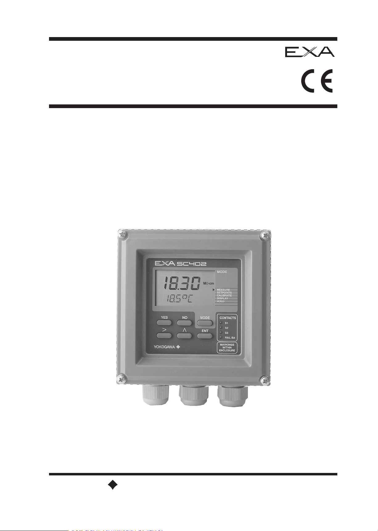
Instruction
Manual
Model SC402G
Conductivity and Resistivity
Converter
IM 12D7C3-E-E
6th Edition
Y
OKOGAWA
Page 2

IM 12D7C3-E-E
TABLE OF CONTENTS
PREFACE
1. INTRODUCTION AND GENERAL DESCRIPTION
. . . . . . . . . . . . . . . . . . . . . . . . . . . . . . . . . . . 1-1
1-1. Instrument check . . . . . . . . . . . . . . . . . . . . . . . . . . . . . . . . . . . . . . . . . . . . . . . . . . . . . . . . . 1-1
1-2. Application . . . . . . . . . . . . . . . . . . . . . . . . . . . . . . . . . . . . . . . . . . . . . . . . . . . . . . . . . . 1-2
2. SC402 SPECIFICATIONS . . . . . . . . . . . . . . . . . . . . . . . . . . . . . . . . . . . . . . . . . . . . . . . . . . . . . . 2-1
2-1. General . . . . . . . . . . . . . . . . . . . . . . . . . . . . . . . . . . . . . . . . . . . . . . . . . . . . . . . . . . 2-1
2-2. Operating specifications . . . . . . . . . . . . . . . . . . . . . . . . . . . . . . . . . . . . . . . . . . . . . . . . . . . . . 2-2
2-3. Model and suffix codes . . . . . . . . . . . . . . . . . . . . . . . . . . . . . . . . . . . . . . . . . . . . . . . . . . . . . . 2-3
3. INSTALLATION AND WIRING
. . . . . . . . . . . . . . . . . . . . . . . . . . . . . . . . . . . . . . . . . . . . . . . . . . . 3-1
3-1. Installation and dimensions . . . . . . . . . . . . . . . . . . . . . . . . . . . . . . . . . . . . . . . . . . . . . . . . . . . 3-1
3-1-1. Installation and site . . . . . . . . . . . . . . . . . . . . . . . . . . . . . . . . . . . . . . . . . . . . . . . . . . . . . 3-1
3-1-2. Mounting methods . . . . . . . . . . . . . . . . . . . . . . . . . . . . . . . . . . . . . . . . . . . . . . . . . . . . . 3-1
3-2. Preparation . . . . . . . . . . . . . . . . . . . . . . . . . . . . . . . . . . . . . . . . . . . . . . . . . . . . . . . . . . 3-3
3-3. Wiring the power supply . . . . . . . . . . . . . . . . . . . . . . . . . . . . . . . . . . . . . . . . . . . . . . . . . . . . . 3-4
3-3-1. General precautions . . . . . . . . . . . . . . . . . . . . . . . . . . . . . . . . . . . . . . . . . . . . . . . . . . . . 3-4
3-3-2. Access to terminal and cable entry. . . . . . . . . . . . . . . . . . . . . . . . . . . . . . . . . . . . . . . . . 3-4
3-3-3. AC power . . . . . . . . . . . . . . . . . . . . . . . . . . . . . . . . . . . . . . . . . . . . . . . . . . . . . . . . . . 3-5
3-3-4. DC power . . . . . . . . . . . . . . . . . . . . . . . . . . . . . . . . . . . . . . . . . . . . . . . . . . . . . . . . . . 3-5
3-3-5. Grounding the housing . . . . . . . . . . . . . . . . . . . . . . . . . . . . . . . . . . . . . . . . . . . . . . . . . . 3-5
3-3-6. Switching on the instrument . . . . . . . . . . . . . . . . . . . . . . . . . . . . . . . . . . . . . . . . . . . . . . 3-5
3-4. Wiring the contact signals . . . . . . . . . . . . . . . . . . . . . . . . . . . . . . . . . . . . . . . . . . . . . . . . . . . . 3-6
3-4-1. General precautions . . . . . . . . . . . . . . . . . . . . . . . . . . . . . . . . . . . . . . . . . . . . . . . . . . . . 3-6
3-4-2. Contact outputs . . . . . . . . . . . . . . . . . . . . . . . . . . . . . . . . . . . . . . . . . . . . . . . . . . . . . . . 3-6
3-5. Wiring the analog output signals . . . . . . . . . . . . . . . . . . . . . . . . . . . . . . . . . . . . . . . . . . . . . . . 3-6
3-5-1. General precautions . . . . . . . . . . . . . . . . . . . . . . . . . . . . . . . . . . . . . . . . . . . . . . . . . . . . 3-6
3-5-2. Analog output signals . . . . . . . . . . . . . . . . . . . . . . . . . . . . . . . . . . . . . . . . . . . . . . . . . . . 3-6
3-6. Sensor wiring . . . . . . . . . . . . . . . . . . . . . . . . . . . . . . . . . . . . . . . . . . . . . . . . . . . . . . . . . . 3-7
3-7. Sensor connection using junction box and extension cable . . . . . . . . . . . . . . . . . . . . . . . . . . 3-7
3-8. Other sensor systems . . . . . . . . . . . . . . . . . . . . . . . . . . . . . . . . . . . . . . . . . . . . . . . . . . . . . . . 3-8
3-9. Tag plate mounting . . . . . . . . . . . . . . . . . . . . . . . . . . . . . . . . . . . . . . . . . . . . . . . . . . . . . . . . . 3-9
4. OPERATION; DISPLAY FUNCTIONS AND SETTINGS
. . . . . . . . . . . . . . . . . . . . . . . . . . . . . . . 4-1
4-1. Operator interface . . . . . . . . . . . . . . . . . . . . . . . . . . . . . . . . . . . . . . . . . . . . . . . . . . . . . . . . . . 4-1
4-2. Explanation of operating keys . . . . . . . . . . . . . . . . . . . . . . . . . . . . . . . . . . . . . . . . . . . . . . . . . 4-2
4-3. Setting passcodes . . . . . . . . . . . . . . . . . . . . . . . . . . . . . . . . . . . . . . . . . . . . . . . . . . . . . . . . . 4-3
4-4. Display example . . . . . . . . . . . . . . . . . . . . . . . . . . . . . . . . . . . . . . . . . . . . . . . . . . . . . . . . . . 4-3
4-5. Display functions . . . . . . . . . . . . . . . . . . . . . . . . . . . . . . . . . . . . . . . . . . . . . . . . . . . . . . . . . . 4-4
5. PARAMETER SETTING
. . . . . . . . . . . . . . . . . . . . . . . . . . . . . . . . . . . . . . . . . . . . . . . . . . . . . . . . 5-1
5-1. Maintenance mode . . . . . . . . . . . . . . . . . . . . . . . . . . . . . . . . . . . . . . . . . . . . . . . . . . . . . . . . . 5-1
5-1-1. Introduction . . . . . . . . . . . . . . . . . . . . . . . . . . . . . . . . . . . . . . . . . . . . . . . . . . . . . . . . . . 5-2
5-1-2. Manual activation of Hold . . . . . . . . . . . . . . . . . . . . . . . . . . . . . . . . . . . . . . . . . . . . . . . . 5-2
5-1-3. Setpoint adjustment . . . . . . . . . . . . . . . . . . . . . . . . . . . . . . . . . . . . . . . . . . . . . . . . . . . . 5-3
5-2. Commissioning mode . . . . . . . . . . . . . . . . . . . . . . . . . . . . . . . . . . . . . . . . . . . . . . . . . . . . . . . 5-4
5-2-1. Introduction . . . . . . . . . . . . . . . . . . . . . . . . . . . . . . . . . . . . . . . . . . . . . . . . . . . . . . . . . . 5-4
5-2-2. Setpoints . . . . . . . . . . . . . . . . . . . . . . . . . . . . . . . . . . . . . . . . . . . . . . . . . . . . . . . . . . 5-5
5-2-3. Range . . . . . . . . . . . . . . . . . . . . . . . . . . . . . . . . . . . . . . . . . . . . . . . . . . . . . . . . . . 5-7
5-2-4. Hold . . . . . . . . . . . . . . . . . . . . . . . . . . . . . . . . . . . . . . . . . . . . . . . . . . . . . . . . . . 5-9
5-2-5. Temperature compensation . . . . . . . . . . . . . . . . . . . . . . . . . . . . . . . . . . . . . . . . . . . . . 5-11
5-2-6. Service . . . . . . . . . . . . . . . . . . . . . . . . . . . . . . . . . . . . . . . . . . . . . . . . . . . . . . . . . 5-13
Page 3

IM 12D7C3-E-E
5-3. Notes for guidance in the use of service coded settings . . . . . . . . . . . . . . . . . . . . . . . . . . . . 5-14
5-3-1. Parameter specific functions. . . . . . . . . . . . . . . . . . . . . . . . . . . . . . . . . . . . . . . . . . . . . 5-14
5-3-2. Temperature measuring functions . . . . . . . . . . . . . . . . . . . . . . . . . . . . . . . . . . . . . . . . 5-16
5-3-3. Temperature compensation functions. . . . . . . . . . . . . . . . . . . . . . . . . . . . . . . . . . . . . . 5-18
5-3-4. mA output functions . . . . . . . . . . . . . . . . . . . . . . . . . . . . . . . . . . . . . . . . . . . . . . . . . . . 5-20
5-3-5. Contact outputs . . . . . . . . . . . . . . . . . . . . . . . . . . . . . . . . . . . . . . . . . . . . . . . . . . . . . . 5-22
5-3-6. User interface . . . . . . . . . . . . . . . . . . . . . . . . . . . . . . . . . . . . . . . . . . . . . . . . . . . . . . . . 5-26
5-3-7. Communication setup . . . . . . . . . . . . . . . . . . . . . . . . . . . . . . . . . . . . . . . . . . . . . . . . . 5-28
5-3-8. General . . . . . . . . . . . . . . . . . . . . . . . . . . . . . . . . . . . . . . . . . . . . . . . . . . . . . . . . . 5-28
5-3-9. Test and setup mode . . . . . . . . . . . . . . . . . . . . . . . . . . . . . . . . . . . . . . . . . . . . . . . . . . 5-28
6. CALIBRATION
. . . . . . . . . . . . . . . . . . . . . . . . . . . . . . . . . . . . . . . . . . . . . . . . . . . . . . . . . . 6-1
6-1. When is calibration necessary? . . . . . . . . . . . . . . . . . . . . . . . . . . . . . . . . . . . . . . . . . . . . . . . . 6-1
6-2. Calibration procedure . . . . . . . . . . . . . . . . . . . . . . . . . . . . . . . . . . . . . . . . . . . . . . . . . . . . . . . 6-2
6-3. Calibration with HOLD active . . . . . . . . . . . . . . . . . . . . . . . . . . . . . . . . . . . . . . . . . . . . . . . . . 6-3
7. MAINTENANCE
. . . . . . . . . . . . . . . . . . . . . . . . . . . . . . . . . . . . . . . . . . . . . . . . . . . . . . . . . . 7-1
7-1. Periodic maintenance for the EXA 402 converter . . . . . . . . . . . . . . . . . . . . . . . . . . . . . . . . . . 7-1
7-2. Periodic maintenance of the sensor . . . . . . . . . . . . . . . . . . . . . . . . . . . . . . . . . . . . . . . . . . . . 7-1
8. TROUBLESHOOTING
. . . . . . . . . . . . . . . . . . . . . . . . . . . . . . . . . . . . . . . . . . . . . . . . . . . . . . . . . . 8-1
8-1. Diagnostics . . . . . . . . . . . . . . . . . . . . . . . . . . . . . . . . . . . . . . . . . . . . . . . . . . . . . . . . . . 8-1
8-1-1. Off-line checks . . . . . . . . . . . . . . . . . . . . . . . . . . . . . . . . . . . . . . . . . . . . . . . . . . . . . . . . 8-1
8-1-2. On-line checks . . . . . . . . . . . . . . . . . . . . . . . . . . . . . . . . . . . . . . . . . . . . . . . . . . . . . . . . 8-1
9. SPARE PARTS
. . . . . . . . . . . . . . . . . . . . . . . . . . . . . . . . . . . . . . . . . . . . . . . . . . . . . . . . . . 9-1
9-1. Itemized parts list . . . . . . . . . . . . . . . . . . . . . . . . . . . . . . . . . . . . . . . . . . . . . . . . . . . . . . . . . . 9-1
10. APPENDIX . . . . . . . . . . . . . . . . . . . . . . . . . . . . . . . . . . . . . . . . . . . . . . . . . . . . . . . . . 10-1
10-1. User setting for non-linear output table (code 31, 35 and 36) . . . . . . . . . . . . . . . . . . . . . . . 10-1
10-2. User entered matrix data (code 23 to 28) . . . . . . . . . . . . . . . . . . . . . . . . . . . . . . . . . . . . . . 10-1
10-3. Matrix data table (user selectable in code 22) . . . . . . . . . . . . . . . . . . . . . . . . . . . . . . . . . . . 10-2
10-4. Sensor Selection . . . . . . . . . . . . . . . . . . . . . . . . . . . . . . . . . . . . . . . . . . . . . . . . . . . . . . . . . 10-3
10-4-1. General . . . . . . . . . . . . . . . . . . . . . . . . . . . . . . . . . . . . . . . . . . . . . . . . . . . . . . . . . 10-3
10-4-2. Sensor selection. . . . . . . . . . . . . . . . . . . . . . . . . . . . . . . . . . . . . . . . . . . . . . . . . . . . . 10-3
10-4-3. Selecting a temperature sensor . . . . . . . . . . . . . . . . . . . . . . . . . . . . . . . . . . . . . . . . . 10-3
10-5. Setup for other functions . . . . . . . . . . . . . . . . . . . . . . . . . . . . . . . . . . . . . . . . . . . . . . . . . . 10-3
10-6. USP <645> . . . . . . . . . . . . . . . . . . . . . . . . . . . . . . . . . . . . . . . . . . . . . . . . . . . . . . . . . 10-8
10-7. User setting table . . . . . . . . . . . . . . . . . . . . . . . . . . . . . . . . . . . . . . . . . . . . . . . . . . . . . . . . 10-4
10-8. Configuration checklist for SC402G . . . . . . . . . . . . . . . . . . . . . . . . . . . . . . . . . . . . . . . . . . 10-6
10-9. Software history . . . . . . . . . . . . . . . . . . . . . . . . . . . . . . . . . . . . . . . . . . . . . . . . . . . . . . . . . 10-9
ERROR CODES
. . . . . . . . . . . . . . . . . . . . . . . . . . . . . . . . . . . . . . . . . . . . . . . . . . . . . . . . 10-10
QUALITY INSPECTION STANDARD & CERTIFICATE
. . . . . . . . . . . . . . . . . . . . . . . . . . . . . . . . 10-11
Page 4

IM 12D7C3-E-E
PREFACE
Electric discharge
The EXA analyzer contains devices that can be damaged by electrostatic discharge. When servicing
this equipment, please observe proper procedures to prevent such damage. Replacement components
should be shipped in conductive packaging. Repair work should be done at grounded workstations using
grounded soldering irons and wrist straps to avoid electrostatic discharge.
Installation and wiring
The EXA analyzer should only be used with equipment that meets the relevant IEC, American or Canadian
standards. Yokogawa accepts no responsibility for the misuse of this unit.
The Instrument is packed carefully with shock absorbing materials, nevertheless, the instrument may be
damaged or broken if subjected to strong shock, such as if the instrument is dropped. Handle with care.
Although the instrument has a weatherproof construction, the transmitter can be harmed if it becomes
submerged in water or becomes excessively wet.
Do not use an abrasive or solvent in cleaning the instrument.
Notice
Contents of this manual are subject to change without notice. Yokogawa is not responsible for damage
to the instrument, poor performance of the instrument or losses resulting from such, if the problems are
caused by:
● Improper operation by the user.
● Use of the instrument in improper applications
● Use of the instrument in an improper environment or improper utility program
● Repair or modification of the related instrument by an engineer not authorized by Yokogawa.
Warranty and service
Yokogawa products and parts are guaranteed free from defects in workmanship and material under normal
use and service for a period of (typically) 12 months from the date of shipment from the manufacturer.
Individual sales organisations can deviate from the typical warranty period, and the conditions of sale
relating to the original purchase order should be consulted. Damage caused by wear and tear, inadequate
maintenance, corrosion, or by the effects of chemical processes are excluded from this warranty coverage.
In the event of warranty claim, the defective goods should be sent (freight paid) to the service department of
the relevant sales organisation for repair or replacement (at Yokogawa discretion). The following information
must be included in the letter accompanying the returned goods:
● Part number, model code and serial number
● Original purchase order and date
● Length of time in service and a description of the process
● Description of the fault, and the circumstances of failure
● Process/environmental conditions that may be related to the installation failure of the device
● A statement whether warranty or non-warranty service is requested
● Complete shipping and billing instructions for return of material, plus the name and phone number of a
contact person who can be reached for further information.
Returned goods that have been in contact with process fluids must be decontaminated/disinfected before
shipment. Goods should carry a certificate to this effect, for the health and safety of our employees. Material
WARNING
CAUTION
Page 5
Introduction 1-1
1. INTRODUCTION AND GENERAL DESCRIPTION
The Yokogawa EXA 402 is a 4-wire transmitter designed for industrial process monitoring, measurement
and control applications. This instruction manual contains the information needed to install, set up, operate
and maintain the unit correctly. This manual also includes a basic troubleshooting guide to answer typical
user questions.
Yokogawa can not be responsible for the performance of the EXA analyzer if these instructions are not
followed.
1-1. Instrument Check
Upon delivery, unpack the instrument carefully and inspect it to ensure that it was not damaged during
shipment. If damage is found, retain the original packing materials (including the outer box) and then
immediately notify the carrier and the relevant Yokogawa sales office.
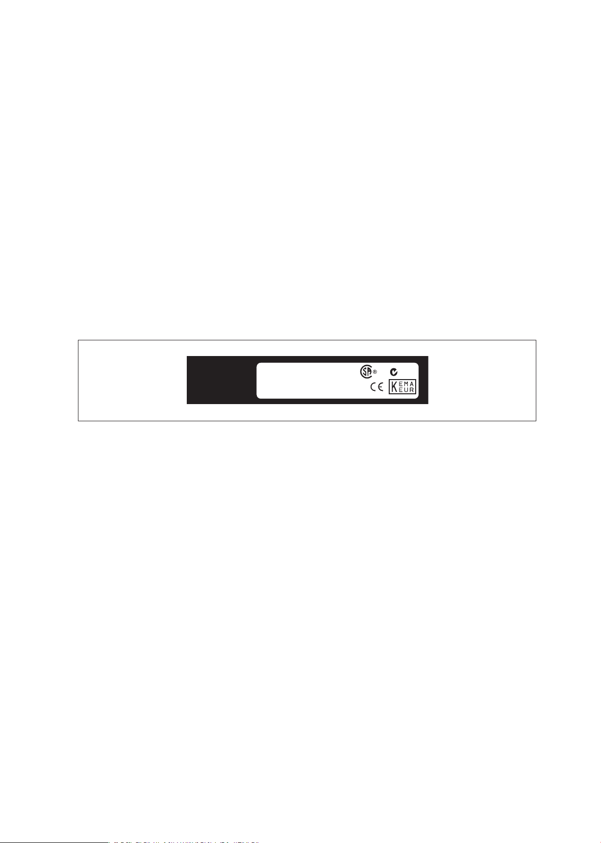
Make sure the model number on the nameplate affixed to the top of the display board of the instrument
agrees with your order.
NOTE:
The nameplate will also contain the serial number and power supply selection.
Be sure to apply correct power to the unit.
Figure 1-1. Nameplate
Check that all the parts are present, including mounting hardware, as specified in the option codes at the
end of the model number. For a description of the model codes, refer to Chapter 2 of this manual under
General Specifications.
Basic Parts List: Converter EXA 402
Instruction Manual (See model code for language)
Packet with 4 screws for mounting on a panel (M6x8mm)
Optional mounting hardware when specified (See model code)
MODEL
SERIAL NO
.
SUPPLY
SC402G-E-1-E
FD 020 034
11
0-120 VAC, 50/60 Hz, 10 VA
N200
IM 12D7C3-E-E
Page 6

IM 12D7C3-E-E
1-2 Introduction
1-2. Application
The EXA converter is intended to be used for continuous on-line measurement in industrial installations. The
unit combines simple operation and microprocessor-based performance with advanced self-diagnostics
and enhanced communications capability to meet the most advanced requirements. The measurement can
be used as part of an automated process control system. It can also be used to indicate dangerous limits
of a process, to monitor product quality, or to function as a simple controller for a dosing/neutralization
system.
Yokogawa designed the EXA analyzer to withstand harsh environments. The converter may be installed
either indoors or outside because the IP65 (NEMA4X) housing and cabling glands ensure the unit is
adequately protected. The flexible polycarbonate window on the front door of the EXA allows pushbutton
access to the keypad, thus preserving the water and dust protection of the unit even during routine
maintenance operations.
A variety of EXA hardware is optionally available to allow wall, pipe, or panel mounting. Selecting a proper
installation site will permit ease of operation. Sensors should normally be mounted closely to the converter
in order to ensure easy calibration and peak performance. If the unit must be mounted remotely from the
sensors, WF10 extension cable can be used up to a maximum of 50 metres (150 feet) with a BA10 junction
box.
The EXA is delivered with a general purpose default setting for programmable items. (Default settings are
listed in Chapter 5 and again in Chapter 10). While this initial configuration allows easy start-up, the
configuration should be adjusted to suit each particular application. An example of an adjustable item is the
type of temperature sensor used. The EXA can be adjusted for any one of five different types of temperature
sensors.
To record such configuration adjustments, write changes in the space provided in Chapter 10 of this
manual. Because the EXA is suitable for use as a monitor, a controller or an alarm instrument, program
configuration possibilities are numerous.
Details provided in this instruction manual are sufficient to operate the EXA with all Yokogawa sensor
systems and a wide range of third-party commercially available probes. For best results, read this manual
in conjunction with the corresponding sensor instruction manual.
Yokogawa designed and built the EXA to meet the CE regulatory standards. The unit meets or exceeds
stringent requirements of EN 55082-2, EN55022 Class A and low voltage safety directive IEC1010 without
compromise, to assure the user of continued accurate performance in even the most demanding industrial
installations.
Page 7

IM 12D7C3-E-E
Specification 2-1
2. SC402G SPECIFICATIONS
2-1. General
A. Input specifications
: Two or four electrodes
measurement with square
wave excitation, using max. 60
m (200 ft) cable (WU40/WF10)
and cellconstants from 0.008
to 50.0 cm-1
B. Detection method
: Frequency, read-pulse position
and reference voltage are
dynamically optimized.
C. Input ranges
- Conductivity : 0.000 µS/cm to 1999 mS/cm
at 25 °C (77 °F) reference
temperature.
- Minimum : 0.1 µS x C at process
temperature
(underrange 0.000 µS/cm).
- Maximum : 500 mS x C at process
temperature
(overrange 550 mS x C).
- Resistivity : 0.000 k1/2 x cm - 999 M1/2 x
cm at 25 °C (77 °F) reference
temperature.
- Minimum : 0.002 k1//C at process
temperature
(underrange 0.000 k1/2 x cm).
- Maximum : 1 M1//C at process
temperature
(overrange 999 M1/2 x cm).
- Temperature
- Pt1000 : -20-250 °C (0-500 °F)
- Pt100/Ni100 : -20-200 °C (0-400 °F)
- 8K55 NTC : -10-120 °C (10-250 °F)
- PB36 NTC : -20-120 °C (0-250 °F)
D. Span
- Conductivity : - min. 0.010 µS/cm,
- max. 1999 mS/cm.
(max 90% zero suppression)
- Resistivity : - min. 0.001 k1/2 x cm
- max. 999 M1/2 x cm.
(max 90% zero suppression)
- Temperature : Dependent on temp. sensor
type:
Sensor type min. max.
Pt1000 25 °C (50 °F) 250 °C (500 °F)
Pt100, Ni100 25 °C (50 °F) 200 °C (400 °F)
PB36NTC, 8K55NTC 25 °C (50 °F) 100 °C (200 °F)
The instrument is user
programmable for linear or
nonlinear conductivity ranges.
E. Transmission signals
: Two isolated outputs of 0/4-20
mA DC with common negative.
Maximum load 600 Ω.
Auxiliary output can be chosen
from conductivity, resistivity,
temperature or PI control Burn
up (22 mA) or Burn down
(0/3.5 mA) to signal failure.
F. Temperature compensation
: Automatic, for temperature
ranges mentioned under C
(inputs).
Reference temp : programmable from 0 - 100 °C
or 30 - 210 °F (default 25 °C).
G. Compensation algorithm
: According IEC 746-3 NaCl
tables (default).
Two independent user
programmable temperature
coefficients, from 0% to 3.5 %
per °C (°F) by adjustment or
calibration.
- Matrix compensation
: With conductivity function
of concentration and
temperature. Choice out of
5 preprogrammed matrices
and a 25- points userprogrammable matrix.
H. Serial Communication
: Bi-directional according to the
EIA-485 standard using HARTprotocol and PC402 software.
I. Logbook : Software record of important
events and diagnostic data.
Available through RS485.
J. Display : Custom liquid crystal display,
with a main display of 31/2
digits 12.5 mm high. Message
display of 6 alphanumeric
characters, 7 mm high.
Warning flags and units (mS/
cm, k1/.cm, µS/cm and M1/.
cm) as appropriate.
Page 8

IM 12D7C3-E-E
2-2 Specifications
K. Contact Outputs
- General : Four (4) SPDT relay contacts
with LED indicators. For S1,
S2, and S3, the LED is on
when relay is powered.
NOTE: For S4 (FAIL) LED lights
when power is removed
(Fail safe).
Contact outputs configurable
for hysteresis and delay time.
- Switch capacity : Maximum values 100 VA, 250
VAC, 5 Amps.
Maximum values 50 Watts,
250 VDC, 5 Amps.
- Status : High/low process alarms,
selected from conductivity,
resistivity and temperature.
Contact output is also available
to signal “Hold active”
- Control function : On / Off
PI pulsed - Proportional
duty cycle control with
integral term.
PI frequency Proportional frequency
control with integral term.
In addition FAIL alarm for
system and diagnostic
errors on S4
L. Contact Input : Remote range switching to
10
times the programmed range.
- Contact open : If impedance > 100 kΩ:
Range 1
- Contact closed : If impedance < 10 Ω: Range 2
(10 x Range 1)
M. Power Supply : - 230 VAC ±15%, 50/60 Hz,
maximum consumption 10 VA.
- 115 VAC ±15%, 50/60 Hz,
maximum consumption 10 VA.
- 100 VAC ±15%, 50/60 Hz,
maximum consumption 10 VA.
- 24 VDC -20% / +30%,
maximum consumption 10
Watts.
N. Input isolation : 1000 VDC
O. Shipping Details
: Package size w x h x d
290 x 225 x 170 mm.
11.5 x 8.9 x 6.7 in. Packed
weight approx. 2.5 kg (5lb).
2-2. Operating specifications
A. Performance : Conductivity
- Linearity :
≤ 0.5 % ± 0.02 mA
- Repeatability : ≤ 0.5 % ± 0.02 mA
- Accuracy : ≤ 0.5 % ± 0.02 mA
Performance : Resistivity
- Linearity : ≤0.02 M1/2 ± 0.02 mA
- Repeatability : ≤0.01 M1/2 ± 0.02 mA
- Accuracy : ≤0.03 M1/2 ± 0.02 mA
Performance : Resistivity (other ranges, up
to 5 MΩ x cm)
- Linearity : ≤0.5 % ± 0.02 mA
- Repeatability : ≤0.5 % ± 0.02 mA
- Accuracy : ≤0.5 % ± 0.02 mA
Performance : Temperature with Pt1000Ω,
Ni100Ω and PB36 NTC
- Linearity : ≤0.3 °C ± 0.02 mA
- Repeatability : ≤0.3 °C ± 0.02 mA
- Accuracy : ≤0.3 °C ± 0.02 mA
Performance : Temperature with PT100Ω
and 8k55Ω
- Linearity : ≤0.4 °C ± 0.02 mA
- Repeatability : ≤0.4 °C ± 0.02 mA
- Accuracy : ≤0.4 °C ± 0.02 mA
Performance : Temperature compensation
- NaCl table : ≤1 %
- Matrix : ≤3 %
- Ambient influence
: ≤ 0.05 %/°C
- Step response : 90 % (< 2 decades)
in ≤ 3 seconds
B. Ambient operating temperature
: -10 to +55 oC (10 to 130 ºF)
Excursions to -30 to +70 °C
(-20 to 160 ºF) will not damage
the instrument
C. Storage temperature
: -30 to +70 °C (-20 to 160 ºF)
D. Humidity : 10 to 90% RH non-condensing
E. Housing : Cast aluminium case
with chemically resistant
coating, cover with flexible
polycarbonate window. Case
color is off-white and cover
is moss green. Cable entry is
via six 1/2” polyamide glands.
Cable terminals are provided
for up to 2.5 mm2 finished
wires. Weather resistant to
IP65 and NEMA 4X standards.
Pipe wall or panel mounting,
using optional hardware.
Page 9

IM 12D7C3-E-E
Specifications 2-3
F. Data protection
: EEPROM for configuration and
logbook, and lithium battery for
clock.
G. Watchdog timer
: Checks microprocessor
H. Automatic safeguard
: Return to measuring mode
when no keystroke is made for
10 min.
I. Power interruption
: Less than 50 milliseconds no
effect.
More than 50 milliseconds
reset to measurement.
J. Operation protection
: 3-digit programmable password.
K. Regulatory compliance
- EMC : meets council directive
89/336/EEC
- Emission : meets EN 55022 Class A
- Immunity : meets EN 50082-2
- Low voltage : meets council directive 73/23/
EEC
- Installation : Designed for installation
conforming to IEC 1010-1,
Category II.
2-3. Model and suffix codes
* For other languages contact local sales office
Model Suffix Option Description
code code
SC402G ................................... Conductivity/resistivity
transmitter
-E ............................... Always E
Supply -1 .......................... 115 Volts 50/60 Hz
voltage -2 .......................... 230 Volts 50/60 Hz
-4 .......................... 24 Volts DC
-5 .......................... 100 Volts 50/60 Hz
Instruction manual -E ................... English language*
Options /U ........ Pipe and wall mounting
hardware
/PM ..... Panel mounting hardware
/Q ........ Quality certificate
/SCT ... Stainless steel tag
Page 10
3-1 Installation and wiring
IM 12D7C3-E-E
3. INSTALLATION AND WIRING
3-1. Installation and dimensions
3-1-1. Installation site
The EXA converter is weatherproof and can be installed inside or outside. It should, however, be installed
as close as possible to the sensor to avoid long cable runs between sensor and converter. In any case, the
total cable length should not exceed 60 meters (200 feet). Select an installation site where:
● Mechanical vibrations and shocks are negligible
● No relay/power switches are in the direct environment
● Access is possible to the cable glands (see figure 3-1)
● The transmitter is not mounted in direct sunlight or severe weather conditions
● Maintenance procedures are possible (avoiding corrosive environments)
The ambient temperature and humidity of the installation environment must be within the limits of the
instrument specifications. (See chapter 2).
3-1-2. Mounting methods
Refer to figures 3-2 and 3-3. Note that the EXA converter has universal mounting capabilities:
● Panel mounting using optional brackets
● Surface mounting on a plate (using bolts from the back)
● Wall mounting on a bracket (for example, on a solid wall)
● Pipe mounting using a bracket on a horizontal or vertical pipe (maximum pipe diameter 50 mm)
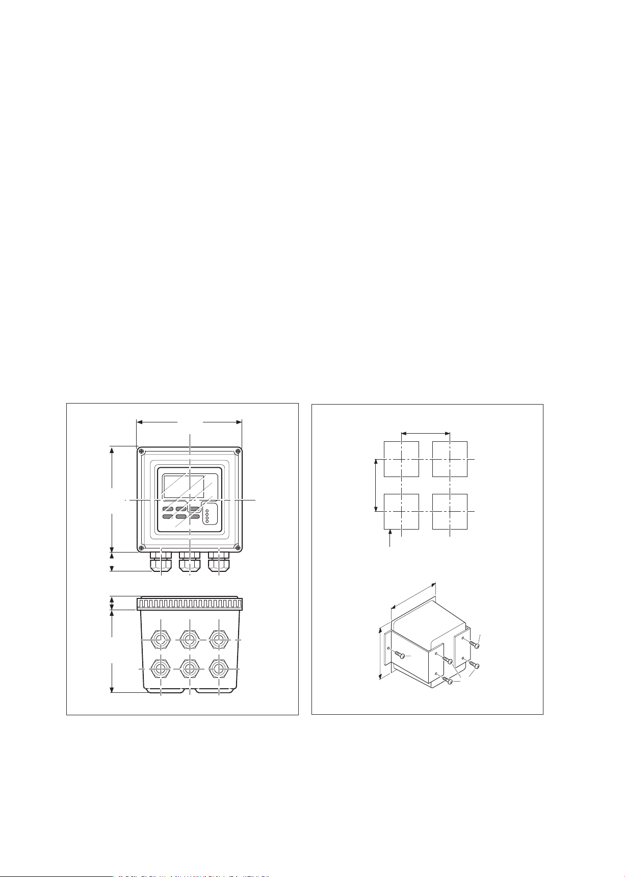
Figure 3-1. Housing dimensions and layout of
glands
Figure 3-2. Panel mounting diagram
144(5.67)
144(5.67)
115.5(4.55)
24(1)
16.5
(0.65)
min. 185 (7.25)
min. 195 (7.75)
cut - out = 138 x 138 (5.43 x 5.43)
138
(5.43)
138
(5.43)
M5
M6
M6
Page 11
IM 12D7C3-E-E
wall mounting
Installation and wiring 3-2
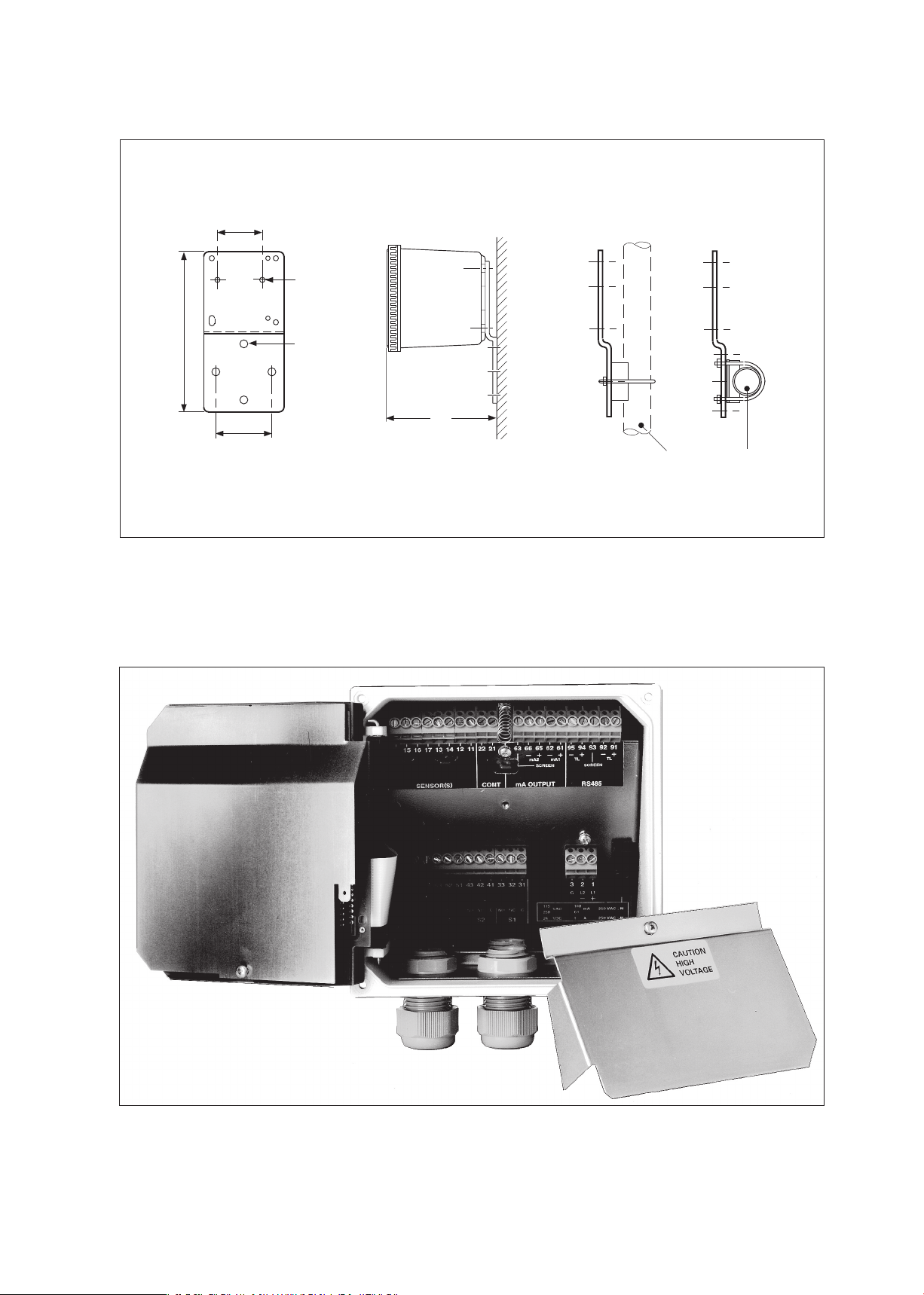
Figure 3-3. Wall and pipe mounting diagram
Figure 3-4. Internal view of EXA wiring compartment
pipe mounting
(horizontal)
80
(3.15)
2x ø6.5
(0.26)
4x ø10
70
(2.75)
145
(5.70)
200
(7.87)
2” ND. pipe
OPTION/U: Universal pipe/wall mounting kit
pipe mounting
(vertical)
(0.4)
Page 12
IM 12D7C3-E-E
3-3 Installation and wiring
3-2. Preparation
Refer to figure 3-4. The relay contact terminals and power supply connections are under the screening
(shielding) plate. These should be connected first. Connect the sensor, outputs and data communication
connections last.
To open the EXA 402 for wiring:
1. Loosen the four frontplate screws and remove the cover.
2. Use the rubber knob in the lower righthand corner and swing open the display board to the left.
3. The upper terminal strip is now visible.
4. Remove the screen (shield) plate covering the lower terminal strip.
5. Connect the power supply and contact outputs. Use the three glands at the back for these cables.
6. Replace the screen (shield) plate over the lower terminals.
Always replace the screen plate over the power and contact outputs for safety and avoid
interference.
7. Connect the analog output(s), the sensor input, and, if necessary, the RS485 serial bus.
8. Use the front three glands for analog output, sensor input, contact input and communication cabling
(see figure 3-5).
9. Close the display board and switch on the power. Commission the instrument as required or use the
default settings.
10. Replace the cover and secure frontplate with the four screws.
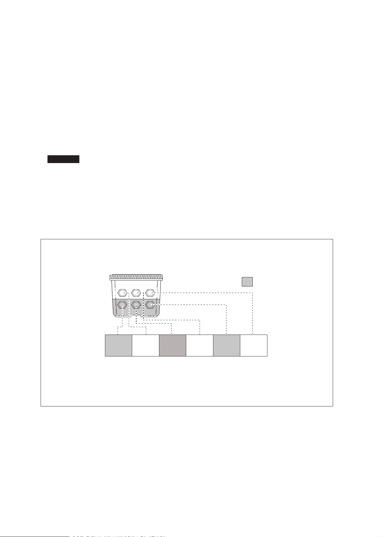
Figure 3-5. Glands to be used for cabling
WARNING
Suitable for cables with an outside diameter between 7 - 12 mm (9/
32
-
15
/
32
in.)
Contact
(S3,S4,FAIL)
output
cables
Sensor
cables
Contact
(S1,S2)
output
cables
Analog
output
cables
Power
cable
Commu-
nication,
contact
input
High voltage section
Page 13
IM 12D7C3-E-E
12D8C3-06
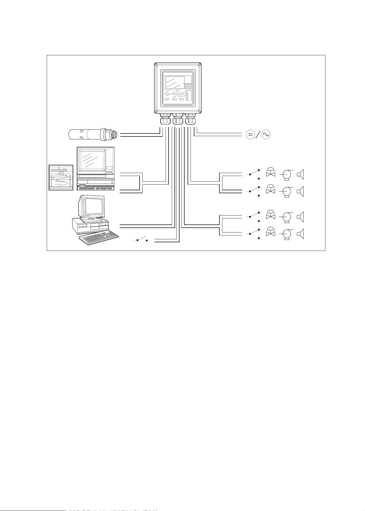
SYSTEM CONFIGURATION
FRONT GLANDS
Sensor
Output
signals
RS485
Power
Contact
output
Contact
output
Contact input
REAR GLANDS
Installation and wiring 3-4
Figure 3-6. System configuration
3-3. Wiring the power supply
3-3-1. General precautions
Make sure the power supply is switched off. Also, make sure that the power supply is correct for the
specifications of the EXA and that the supply agrees with the voltage specified on the textplate. Remove the
front cover by unscrewing the four screws to check this nameplate on the top of the display board.
Local health and safety regulations may require an external circuit breaker to be installed. The instrument is
protected internally by a fuse. The fuse rating is dependent on the supply to the instrument. The 250 VAC
fuses should be of the “time-lag” type, conforming to IEC127.
Fuse ratings are 230 VAC - 50 mA; 100 VAC - 100 mA; 115 VAC - 100 mA; 24 VDC - 1.0 A.
The internal fuse is located next to the power terminals (in the lower right hand corner).
3-3-2. Access to terminal and cable entry
Terminals 1, 2 and 3 on the bottom terminal strip are used for the power supply. Guide the power cables
through the gland closest to the power supply terminals. The terminals will accept wires of 2.5 mm
2
(14
AWG). Use cable finishings if possible.
Connect the wires as indicated in the wiring diagram (refer to figure 3-6).
S1
S2
S3
S4/FAIL
Page 14
IM 12D7C3-E-E
3-5 Installation
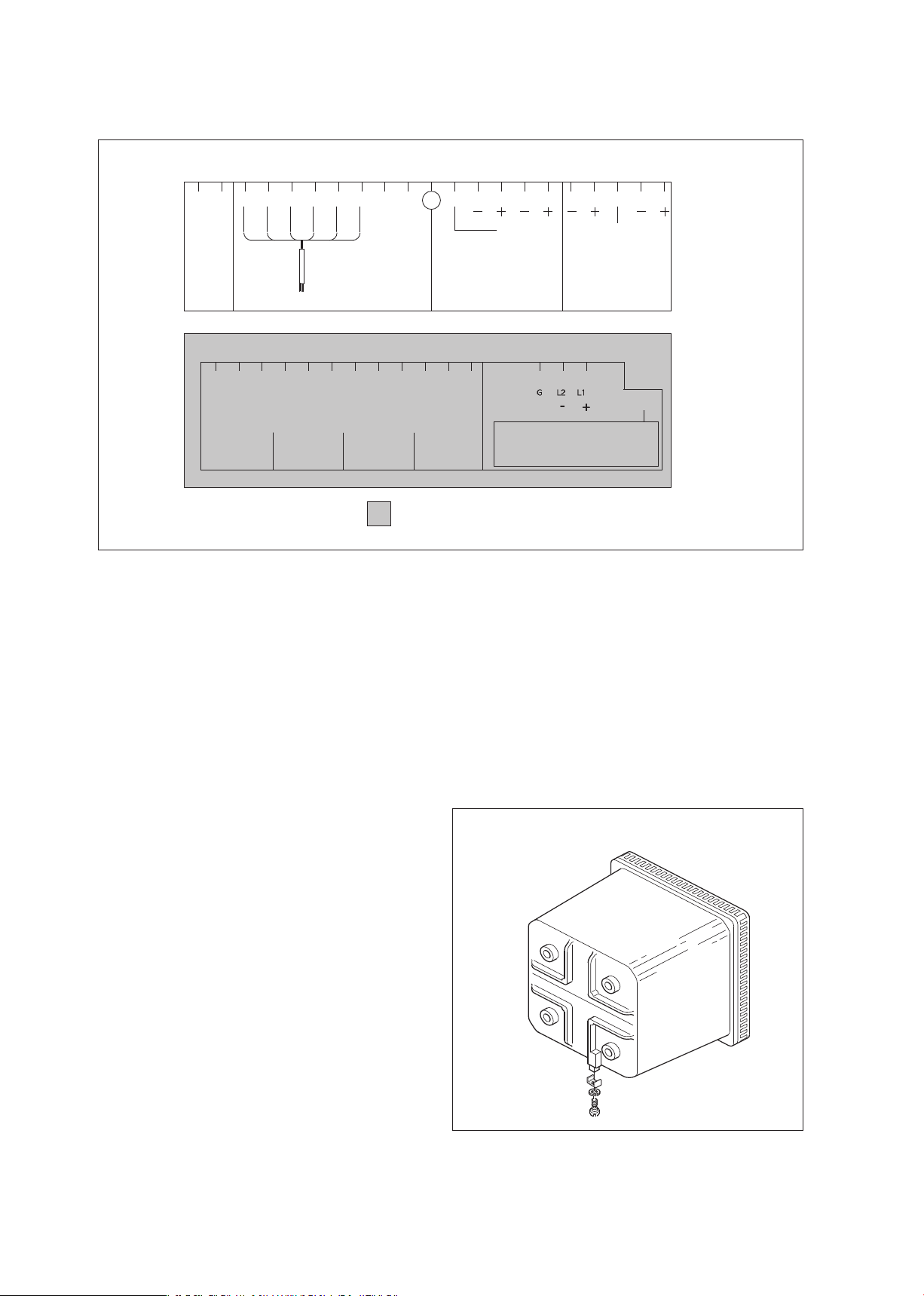
Figure 3-7. Input and output connections
3-3-3. AC power
Connect terminal 1 to the phase line of the AC power and terminal 2 to the zero line. Terminal 3 is for the
power ground. This is separated from input ground by a galvanic isolation.
3-3-4. DC power
Connect terminal 1 to the positive outlet and terminal 2 to the negative outlet. Terminal 3 is for the power
ground. This is separated from input ground by a galvanic isolation. A 2-core screened cable should be
used with the screen connected to terminal 3. The size of conductors should be at least 1.25 mm2. The
overall cable diameter should be between 7 and 12 mm.
3-3-5. Grounding the housing
To protect the instrument against interference, the
housing should be connected to ground by a large
area conductor. This cable can be fixed to the rear of
the housing using a braided wire cable.
See figure 3-8.
3-3-6. Switching on the instrument
After all connections are made and checked, the
power can be switched on from the power supply.
Make sure the LCD display comes on. All segments
will illuminate, then the instrument will momentarily
display its unique serial number. After a brief interval,
the display will change to the measured value. If
errors are displayed or a valid measured value is not
shown, consult the troubleshooting section (Chapter
8) before calling Yokogawa.
Figure 3-8. Grounding the housing
131415
11
12
16
22 21
63 66 65 62 61 95 94 93 92 91
SENSOR
CONT
SCREEN
mA2
mA1
SCREEN
TL TL
Sensor Inputs
Contact
Input
mA Outputs
Digital
Communications
71
S4
S3
S2
S1
C NC NO
72 73 51 52 53 41 43 31 3342 32
250 VAC
5 A
100 VA
250 VDC
5
A
50
W
FUSE
100
11
5
230
24
250V
AC; T
3 12
C NC NO C NC NO C NC NO
VAC
VA
C
VA
C
VDC
100 mA
100 mA
50 mA
1
A
Relay Contacts Power Supply
12D7C3-01
CONNECTION DIAGRAMS
High voltage compartment
Page 15

IM 12D7C3-E-E
Installation 3-6
3-4. Wiring the contact signals
3-4-1. General precautions
The contact output signals consist of voltage-free relay contacts for switching electrical appliances (SPDT).
They can also be used as digital outputs to signal processing equipment (such as a controller or PLC). It is
possible to use multi-core cables for the contact in and output signals and shielded multi-core cable for the
analog signals.
3-4-2. Contact outputs
The EXA unit’s four contact outputs can be wired to suit your own custom requirements (Figure 3-6).
In the Non-Alarm or Power Off states, contacts S1, S2 and S3 are OFF, Common (C) and Normally Closed
(NC) are in contact.
In the “Fail” or Power Off states, contact S4 is ON, Common (C) and Normally Closed (NC) are in contact.
You can either use them to switch AC power, or switch a DC Voltage for digital interfacing.
Default settings
● The contact S1 is pre-programmed for high alarm function.
● The contact S2 is pre-programmed for a low alarm function.
● The contact S3 is not activated as an alarm (off).
● The contact S4 is pre-programmed for FAIL.
The three control contacts (S1 to S3) can be used for simple process control by programming their function
(Chapter 5). The FAIL contact is programmed to signal a fault in the measuring loop. Always connect the
FAIL contact to an alarm device such as a warning light, sound annunciator, or alarm panel to make full use
of the fault detection possibilities (self diagnostics) of the EXA converter.
3-5. Wiring the analog output signals
3-5-1. General precautions
The analog output signals of the EXA transmit low power standard industry signals to peripherals like
control systems or strip-chart recorders (Figure 3-6).
3-5-2. Analog output signals
The output signals consist of active current signals of either 0-20 mA or 4-20 mA. The maximum load can
be 600 ohms on each.
It is necessary to use screening/shielding on the output signal cables. Terminal 63 is used to connect the
shielding.
Page 16
IM 12D7C3-E-E
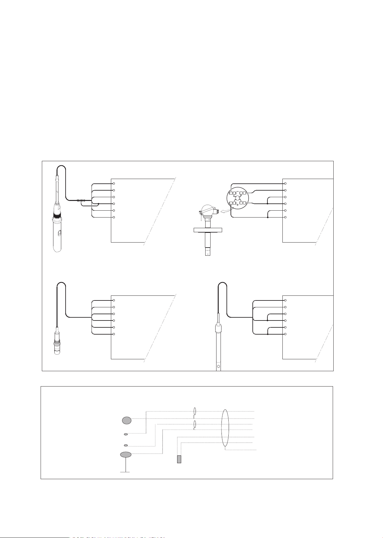
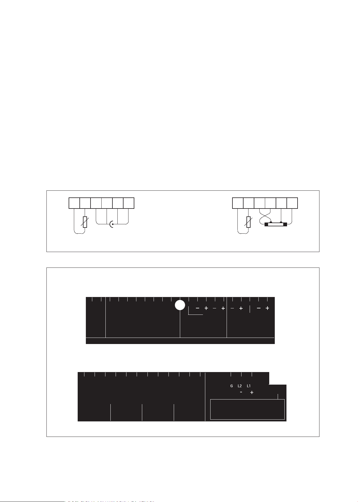
3-6. Sensor wiring
Refer to figure 3-9, which includes drawings that outline sensor wiring.
The EXA SC402G can be used with a wide range of commercially available sensor types if provided with
shielded cables, both from Yokogawa and other manufacturers. The sensor systems from Yokogawa fall
into two categories, the ones that use fixed cables and the ones with separate cables.
To connect sensors with fixed cables, simply match the terminal numbers in the instrument with the
identification numbers on the cable ends.
The separate sensors and the WU40-LHkk cables are also numbered, but the numbers do not always
match with the terminal numbers in the instrument. Figure 3-9 indicates how to connect the different sensor
types.
Figure 3-9. Sensor wiring diagrams
3-7 Installation
11 TEMPERATURE
12 TEMPERA
TURE
13 CELL
14 CELL
15 CELL
16 CELL
CONDUCTIVITY / RESISTIVITY TRANSMITTER
SEPARATE SENSORS WITH WU40-LH . . CABLE
11 TEMPERATURE
12 TEMPERATUR
E
13 OUTER ELECTRODE
14 OUTER ELECTRODE
15 INNER ELECTROD
E
16 INNER ELECTROD
E
RED
GREE
N
WHITE
BLACK
11 TEMPERATURE
12 TEMPERATURE
13 CELL
14 CELL
15 CELL
16 CELL
RED
11 TEMPERATURE
12 TEMPERA
TURE
13 OUTER ELECTRODE
14 OUTER ELECTRODE
15 INNER ELECTROD
E
16 INNER ELECTROD
E
YELLOW / GREEN
BROWN
BROWN
1
2
1
2
SX42-SX . . - . F SENSORS
12D7C3-06
NOTE: Use shielded cable
A-15
B-16
C-13
D-14
E-11
F-12
S-3 or 63
temp
>Connections differential 4-electrode
Page 17
IM 12D7C3-E-E
3-7. Sensor connection using junction box and extension cable
Where a convenient installation is not possible using the standard cables between sensors and converter, a
junction box and extension cable may be used. The Yokogawa BA10 junction box and the WF10 extension
cable should be used. These items are manufactured to a very high standard and are necessary to ensure
that the specifications of the system can be met. The total cable length should not exceed 60 metres (e.g.
10 m fixed cable and 50 m extension cable).
Note: Numbers 17 of both WF10 and BA10 do not need to be used.
3-8. Other sensor systems
To connect other sensor systems, follow the general pattern of the terminal connections as listed below:
11 and 12 Always used for temperature compensation resistor input (Pt1000, Ni100, Pt100, PB36
and 8k55)
14 Normally used for the outer electrode
15 Used for inner electrode
In case a 4-electrode measuring system will be used, 14 and 16 should be used for the current electrodes.
Please ensure that shielded cabling will be used.
In figure 3-10 this is shown in a schematic way.
Figure 3-10. Connection diagram for other sensors
Figure 3-11. Terminal identification labels
Sensor Inputs
Contact
Input
mA Outputs
Digital
Communications
SCREEN
mA2
mA1
TL
SENSOR
mA OUTPUT RS485
CONT
REFER TO
INSTRUCTION MANUAL FOR CONNECTIONS
1516 131412 11
22 21 63 66 65
62
61
95
94 93 92 91
SCREEN
TL
Relay Contacts
Power Supply
71
S4
S3
S2
S1
C NC NO
72 73 51 52 53 41 43 31 3342 32
250VAC
5A
100V
A
250VDC
5A
50W
FUSE
100
11
5
230
24
250V
AC; T
3 12
C NC NO C NC NO C NC NO
VAC
VA
C
VA
C
VDC
100 mA
100 mA
50 mA
1
A
12D7C3-05
INPUT & OUTPUT
CONNECTIONS
Installation 3-8
11 12 13 14 15 16
t
11 12 13 14 15 16
t
12D7C2-10
2-/4 ELECTRODES SYSTEM
2-electrode configuration
4-electrode configuration
Page 18
IM 12D7C3-E-E
3-9 Installation
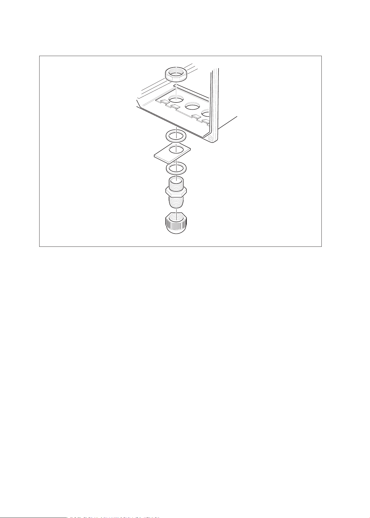
Figure 3-12. Sensor cable connections with tag plate
3-9. Tag plate mounting
When option /SCT is specified, a stainless steel tagplate is supplied with the designated Tag No. stamped
or engraved. It is mounted as shown in figure 3-12 using one of the cable glands.
12D7C3-15
GLANDS EXA 402
Page 19

Operation 4-1
4. OPERATION; DISPLAY FUNCTIONS AND SETTING
4-1. Operator interface
This section provides an overview of the operation of the EXA operator interface. The basic procedures
for obtaining access to the three levels of operation are described briefly. For a step-by-step guide to data
entry, refer to the relevant section of this instruction manual. Figure 4-1 shows the EXA operator interface.
LEVEL 1: Maintenance
These functions are accessible by pushbutton through a flexible front cover window. The functions make up
the normal day-to-day operations that an operator may be required to complete. Adjustment of the display
and routine calibration are among the features accessible in this way. (See table 4-1).
LEVEL 2: Commissioning
A second menu is exposed when the EXA front cover is removed and the display board is revealed. Users
gain access to this menu by pressing the button marked
*
in the lower right of the display board. This menu
is used to set such values as the output ranges and hold features. It also gives access to the service menu.
(See table 4-1).
LEVEL 3: Service
For more advanced configuration selections, press the button marked
*
, then press “NO” repeatedly until
you reach SERVICE. Now push the “YES” button. Selecting and entering “Service Code” numbers in the
commissioning menu provide access to the more advanced functions. An explanation of the Service Codes
is listed in chapter 5 and an overview table is shown in chapter 10.
Table 4-1. Operations overview
Routine Function Chapter
Maintenance SETPOINTS Adjust alarm setpoints (when activated) 5
CALIB Calibration with a standard solution or a sample 6
DISPLAY Read auxiliary data or set message display 4
HOLD Switch hold on/off (when activated) 5
Commissioning SETPOINTS Adjust alarm setpoints 5
RANGE Adjust the output range 5
SET HOLD Activate the hold function 5
TEMP Select method of temperature compensation 5
Service SERVICE Fine tune the specialized functions of the 5
(Access to coded entries converter
from the commissioning
level)
Note: All three levels may be separately protected by a password. See Service Code 52 in chapter 5
Service Code table for details on setting passwords.
IM 12D7C3-E-E
Page 20
IM 12D7C3-E-E
4-2 Operation
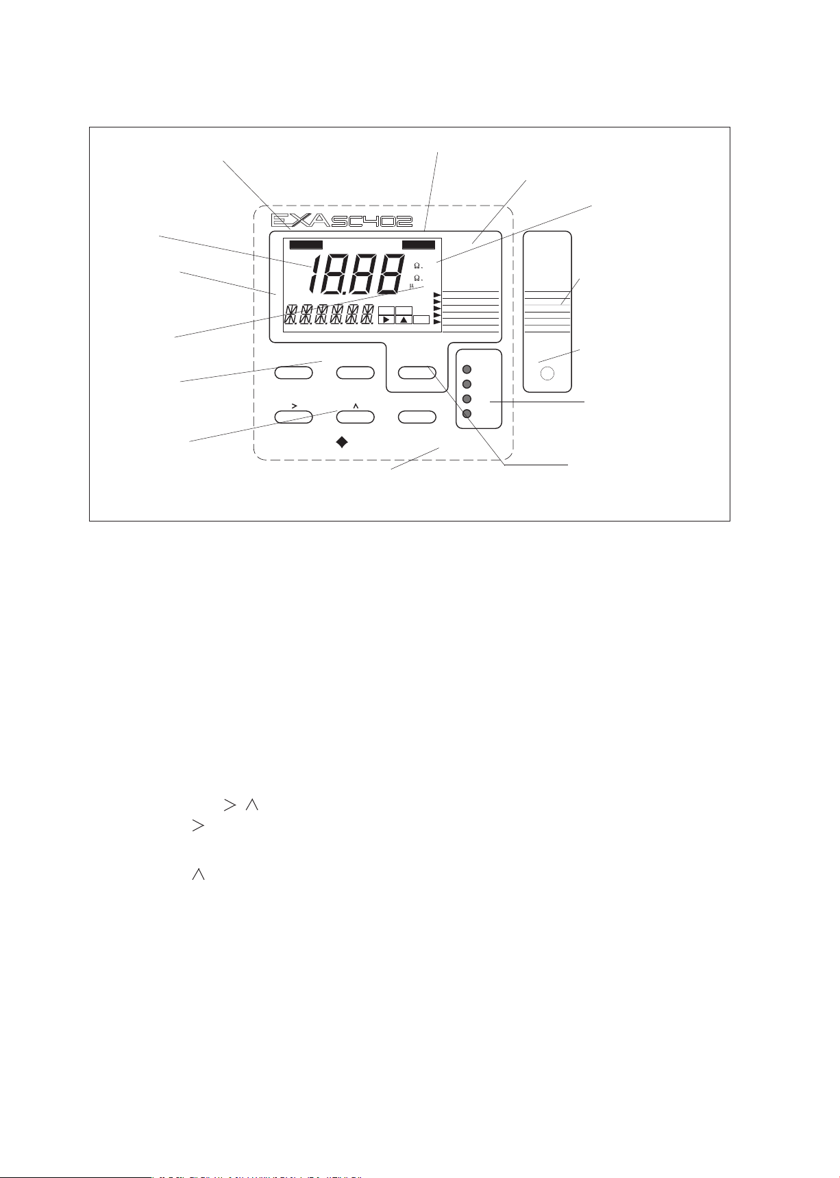
Figure 4-1. SC402G operator interface
4-2. Explanation of operating keys
MODE key This key toggles between the measuring and maintenance modes. Press once to obtain
access to the maintenance function menu.
SETPOINTS
CALIBRATE
DISPLAY
HOLD
Press again to return to the measuring mode (press twice when hold is activated).
YES/NO keys These are used to select choices from the menu.
YES is used to accept a menu selection.
NO is used to reject a selection, or to move ahead to the next option.
DATA ENTRY keys ( ENT)
is used as a “cursor” key. Each press on this key moves the cursor or flashing digit
one place to the right. This is used to select the digit to be changed when entering
numerical data.
is used to change the value of a selected digit. Each press on this key increases
the value by one unit. The value can not be decreased, so in order to obtain a lower
value, increase past nine to zero, then increase to the required number.
ENT When the required value has been set using the > & ^ keys, press ENT to confirm
the data entry. Please note that the EXA 402 does not register any change of data
until the ENT key is pressed.
*
This is the commissioning mode key. It is used to obtain access to the commissioning menu.
This can only be done with the cover removed or opened. Once this button has been used to
initiate the commissioning menu, follow the prompts and use the other keys as described above.
HOLD
FAIL
YES
NO
ENT
SETPOINTS
RANGE
SET HOLD
SERVICE
*
MEASURE
CALIBRATE
DISPLAY
HOLD
NO MODEYES
ENT
YOKOGAWA
MODE
TEMP.
CONTACTS
S1
S2
S3
FAIL/S4
m S/ c m
S /c m
k c m
M c m
SETPOINTS
12D7C3-13
FRONT EXA SC402
Output hold flag
Fail flag
Menu pointer flags
Commissioning
function menu
Commissioning
mode access key
Relay contact
status indicators
Measure/Maintenance
mode key
Broken line indicates area
that can be seen through
front cover
Adjustment keys
> : Choose digit to
adjust
^ : Adjust digit
ENT : Confirm change
Selection keys
YES : Accept setting
NO : Change setting
Key prompt flags
Message display
Main display
Units
Page 21

IM 12D7C3-E-E
Operation 4-3
4-3. Setting passcodes
In Service Code 52, EXA users can set passcode protection for each one of the three operating levels, or
for any one or two of the three levels. This procedure should be completed after the initial commissioning
(setup) of the instrument. The passcodes should then be recorded safely for future reference.
When passcodes have been set, the following additional steps are introduced to the configuration and
programming operations:
Maintenance
Press MODE key. The display shows 000 and *PASS*
Enter a 3-digit passcode as set in Service Code 52 to obtain access to the Maintenance Mode
Commissioning
Press
*
key. The display shows 000 and *PASS*
Enter a 3-digit passcode as set in Service Code 52 to obtain access to the Commissioning Mode.
Service
From the commissioning menu, select *Service by pressing YES key. The display shows 000 and *PASS*
Enter a 3-digit passcode as set in Service Code 52 to obtain access to the Service Mode.
Note: See Service Code 52 for the setting of passcodes.
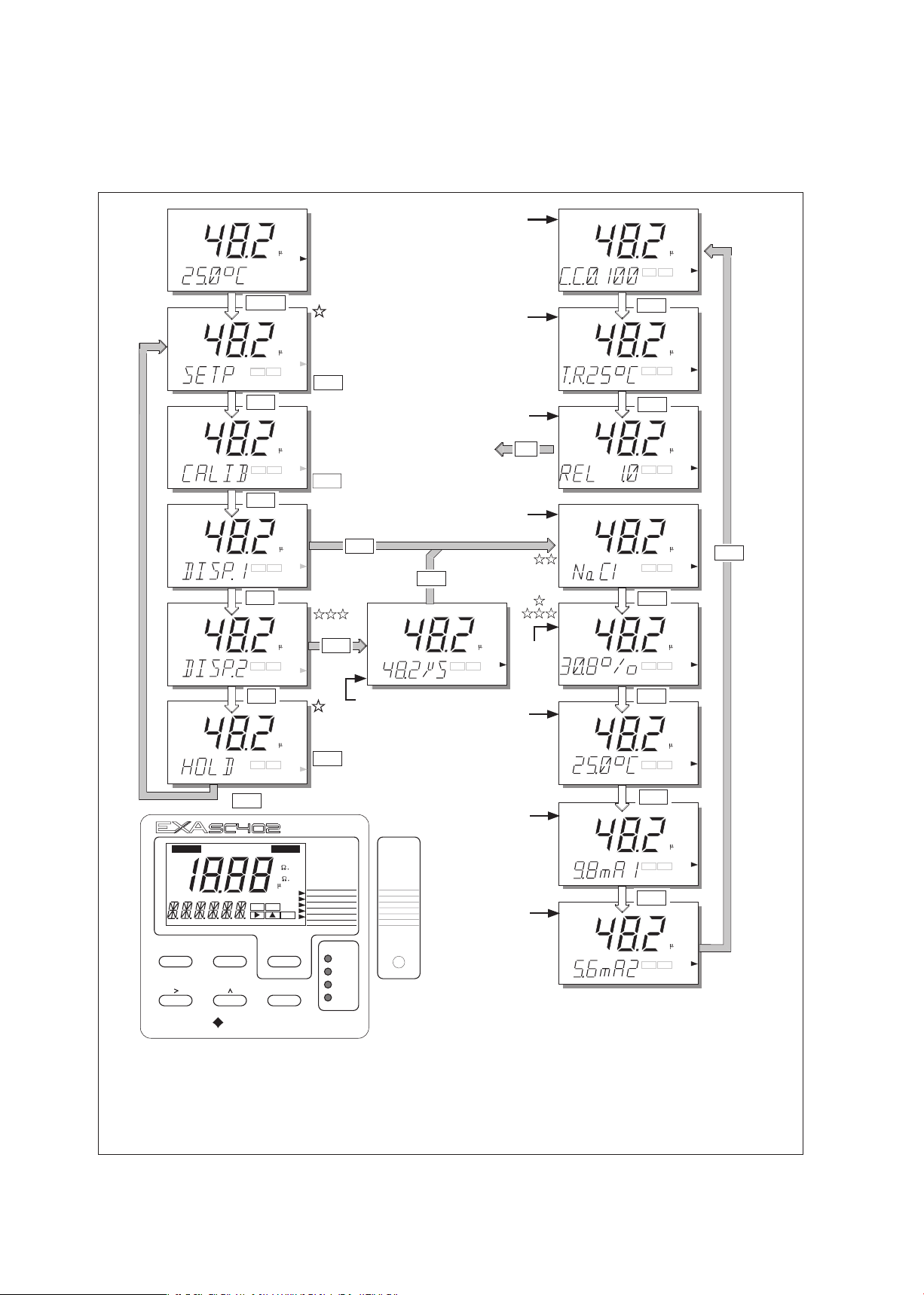
4-4. Display example
The next page shows the sequence of button presses and screens displayed when working in default
configuration.
More or less options will be made available by the configuration of some service codes, or by choices made
in the commissioning menu.
The following deviations are possible:
Items marked are omitted when switched off in commissioning mode and/or service code 51.
Temperature compensation will be displayed dependent on chosen compensation method:
NaCl, TC 2.1 or matrix.
DISP.2 only appears if mA2 is configured for a 2nd (different) temperature compensation
or if % by weight.2 is enabled in code 55.
W/W % only appears if switched on in service code 55.
Page 22
IM 12D7C3-E-E
4-5. Display functions
Sequence for resistivity function parallels this conductivity example.
4-4 Operation
S /c m
YES
(See Setpoint
menu Chapter 5.2)
YES
NO
YES
NO
S /c m
NO
NO
Current
output 2
Press YES to fix
the selected second
line of display
YES
NO
YES
NO
S /c m
S /c m
Process
tempe-
rature
Current
output 1
YES
NO
S /c m
12D7C3-20
Display Functions
(Sequence for resistivity function equals this conductivity example).
MODE
NO
NO
YES
(See Hold
menu Chapter 5.1)
NO
NO
NO
NO
NO
Actual cell constant
Temperature
compensation
for mA1 or
mA2 (DISP.2)
Software
release
number
YES
NO
YES
NO
YES NO
YES NO
YES
NO
YES
NO
YES
NO
YES
NO
SETPOINTS
RANGE
SET HOLD
SERVICE
*
TEMP.
HOLD FAIL
YES NO
ENT
m S/ c m
S /c m
k c m
M c m
MEASURE
CALIBRATE
DISPLAY
HOLD
NO MODEYES
ENT
YOKOGAWA
MODE
CONTACTS
S1
S2
S3
FAIL/S4
SETPOINTS
S /c m
S /c m
S /c m
S /c m
S /c m
S /c m
S /c m
S /c m
S /c m
Reference
temperature
NO
NO
YES
YES
NO
DISP.1
or
DISP.2
2
nd
compensated
value
YES NO
S /c m
NO
NO
w/w %
YES
(See Calibration
menu Chapter 6)
Page 23
IM 12D7C3-E-E
Parameter setting 5-1
5. PARAMETER SETTING
5-1. Maintenance mode
5-1-1. Introduction
Standard operation of the EXA instrument involves use of the Maintenance (or operating) mode to set up
some of the parameters.
Access to the maintenance mode is available via the six keys that can be pressed through the flexible
window in the instrument front cover. Press the “MODE” key once to enter this dialog mode.
(Note that at this stage the user will be prompted for a pass code where this has been previously set up in
service code 52, section 5.)
Setpoint Select and adjust setpoint (when enabled in service menu section 5-3, service
code 51). See adjustment procedure 5-2-2.
Calibrate See “calibration” section 6.
Display setting See “operation” section 4.
Hold Manually switch on/off “hold” (when enabled in commissioning menu). See adjustment
procedure 5-2-4.
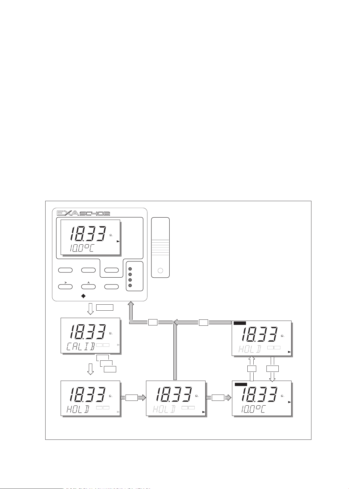
5-1-2. Manual activation of Hold
NO MODEYES
ENT
YOKOGAWA
MODE
CONTACTS
S1
S2
S3
FAIL/S4
12D7C3-27
YES
NO
MODE
NO
NO
NO
YES
NO
YES
M c m
HOLD
YES
NO
5.1.2 Manual Activation of Hold.
Note
: The HOLD feature must first be activated in the commissioning mode section 5.2.4
YES
NO
MEASURE
M c m
M c m
CALIBRATE
SETPOINTS
RANGE
SET HOLD
SERVICE
*
TEMP.
M c m
MEASURE
M c m
NO
YES
M c m
NO
HOLD
NO
YES
Page 24

IM 12D7C3-E-E
5-1-3. Setpoint adjustment
MEASURE
NO MODEYES
ENT
YOKOGAWA
MODE
CONTACTS
S1
S2
S3
FAIL/S4
SETPOINTS
RANGE
SET HOLD
SERVICE
*
TEMP.
12D7C3-29
YES
NO
NO
YES
YES
NO
YES
NO
YES
NO
YES
YES
For adjustments,
follow procedures
as in section 5.2.2
For adjustments,
follow procedures
as in section 5.2.2
Setpoint 3 and 4
when enabled in
service codes
42 and 4
3
Setpoint analog
control output (mA2)
when enabled in code 31
m S/ c m
m S/ c m
m S/ c m
m S/ c m
MODE
5.1.3 Setpoint Adjustment
Note: To enable adjustment of setpoints in
maintenance mode, Service Code 51
must be set to "ON".
Setpoints available will depend on their
configuration in the Service Code.
m S/ c m
NO
YES
5-2 Parameter setting
Page 25

IM 12D7C3-E-E
Parameter setting 5-3
5-2. Commissioning mode
5-2-1. Introduction
In order to obtain peak performance from the EXA SC402, you must set it up for each custom application.
Setpoints Alarms are set by default S1 - high process alarm
S2 - low process alarm
S3 - not activated
S4 - Fail
The setpoints are at arbitrary default value. Therefore, you must set these to meaningful
values, or set them to off. (See service codes 40 to 49 and user interface codes 50 to 59.)
Output ranges mA output 1 is set as default to 0-1 mS/cm or 0-19.99 M
Ω.cm.
For enhanced resolution in more stable measuring processes, it may be desirable to select
5-10 µS/cm range, for example, and maybe 0-25 °C temperature range.
Service codes 30 to 39 can be used to choose other output parameters on mA output 2.
Choose from Table, temperature or PI control.
Hold The EXA SC402G converter has the ability to “HOLD” the output during maintenance
periods. This parameter should be set up to hold the last measured value, or a fixed value
to suit the process.
Service This selection provides access to the service menu.
What follows are pictorial descriptions of typical frontplate pushbutton sequences for each parameter
setting function. By following the simple YES/NO prompts and arrow keys, users can navigate through the
process of setting range, setpoints, hold and service functions.
Page 26

IM 12D7C3-E-E
5-2-2. Setpoints
ENT
ENT
ENT
ENT
ENT
ENT
ENT
ENT
repeated
keystrokes
S / c m
S / c m
S / c m
S / c m
S / c m
S / c m
S / c m
S / c m
YES
NO
NO
NO
NO
NO
YES
NO
SETPOINTS
RANGE
SET HOLD
SERVICE
*
S / c m
MEASURE
DISPLAY
HOLD
MODE
12D7C3-30
5.2.2 Setpoints
TEMP.
CALIBRATE
SETPOINTS
NO
NO
NO
YES
NO
YES
NO
YES
NO
YES
NO
YES
NO
YES
NO
YES
NO
YES
5-4 Parameter setting
Page 27

IM 12D7C3-E-E
Parameter setting 5-5
NOYES
NOYES
NO
NOYES
Process Alarms on
S.3 and S.4 are
only available when
enabled in Service
Codes 40-49
ENT
S /c m
NOYES
NO
Analog control setpoint
is only available when
enabled in Service Code 31
NO
YES
S /c m
ENT
ENT
ENT
ENT
S /c m
Setpoint confirmed.
Return to mode
commissioning.
Adjust setpoint value
using > ENT keys
as shown for setpoint 1
.
>
ENT
ENT
ENT
ENT
ENT
ENT
ENT
ENT
ENT
Negative signs only appear for temp. settings.
12D7C3-31
Page 28

IM 12D7C3-E-E
5-2-3. Range
YES
NO
YES
NO
NO
NO
YES
SETPOINTS
RANGE
SET HOLD
SERVICE
*
MEASURE
CALIBRATE
DISPLAY
HOLD
MODE
TEMP.
5.2.3 Range
12D7C3-32
S / c m
SETPOINTS
YES
NO
YES
ENT
YES
NO
See facing
page
ENT
ENT
ENT
ENT
ENT
ENT
ENT
ENT
YES
NO
YES
NO
S / c m
NO
YES
NO
YES
NO
NO
NO
NO
YES
NO
m S / c m
S / c m
S / c m
S / c m
S / c m
S / c m
S / c m
5-6 Parameter setting
Page 29

IM 12D7C3-E-E
Parameter setting 5-7
YES
NO
NO
ENT
12D7C3-33
YES
ENT
YES
ENT
ENT
ENT
Note: Range 2 does not
appear when PI control
set on mA2
Range Selection Options
are determined
by Service Code 31
ENT
ENT
Choose Range to adjust, then set begin scale (0%)
and end scale (100%) of the mA output signal, using
the
>, ,and ENT keys. Selection of mA output
(0-20 / 4-20 mA) is in Service Code 30
.
>
ENT
Range values set, return
to commission mode
.
YES
NO
YES
NO
YES
NO
YES
NO
YES
NO
OR
YES
The decimal point and unit setting can be changed
as described before in Setpoint Settings.
S /c m
S /c m
Page 30

IM 12D7C3-E-E
5-2-4. Hold
HOLD active
last measured
value.
YES
12D7C3-34
NO
YES NO
YES
NO
NO
YES
NO
YES
NO
YES
NO
NO
NO
NO
S / c m
SETPOINTS
RANGE
SET HOLD
SERVICE
*
MEASURE
CALIBRATE
DISPLAY
HOLD
MODE
TEMP.
NO
YES NO
SETPOINTS
5.2.4 Hold
YES
NO
YES NO
YES
YES
NO
YES
NO
YES
NO
YES
NO
YES
NO
HOLD deactivated, return
to commissioning menu.
HOLD
YES
HOLD
5-8 Parameter setting
Page 31

IM 12D7C3-E-E
Parameter setting 5-9
YES
NO
ENT
HOLD
HOLD
HOLD
HOLD
HOLD
ENT
HOLD
ENT
ENT
ENT
HOLD values set,
return to commissioning
menu.
ENT
ENT
Set HOLD "fixed value"
for mA2.
12B6B3-35
YES
Set HOLD "fixed value"
for mA1.
Page 32

IM 12D7C3-E-E
5-2-5. Temperature compensation
1. Why temperature compensation?
The conductivity of a solution is very dependent on temperature. Typically for every 1 °C change in
temperature the solution conductivity will change by approximately 2 %.
The effect of temperature varies from one solution to another and is determined by several factors like
solution composition, concentration and temperature range.
A coefficient () is introduced to express the amount of temperature influence in % change in
conductivity/°C.
In almost all applications this temperature influence must be compensated before the conductivity reading
can be interpreted as an accurate measure of concentration or purity.
Table 5-1. NaCl-compensation according to IEC 746-3 with T
ref
= 25 °C
2. Standard temperature compensation
From the factory the EXA is calibrated with a general temperature compensation function based
on a sodium chloride salt solution. This is suitable for many applications and is compatible with the
compensation functions of typical laboratory or portable instruments.
A temperature compensation factor is derived from the following equation:
=
Kt - K
ref
x
100
T - T
ref
K
ref
In which:
= Temperature compensation factor
(in %/ °C)
T = Measured temperature (°C)
Kt = Conductivity at T
T
ref
= Reference temperature (°C)
K
ref
= Conductivity at T
ref
3. Manual temperature compensation
If the standard compensation function is found to be inaccurate for the sample to be measured, the
converter can be set manually for a linear factor on site to match the application.
The procedure is as follows:
1. Take a representative sample of the process liquid to be measured.
2. Heat or cool this sample to the reference temperature of the converter (usually 25 °C).
3. Measure the conductivity of the sample with the EXA and note the value.
4. Bring the sample to the typical process temperature (to be measured with the EXA).
5. Adjust the display indication to the noted value at the reference temperature
6. Check that the temperature compensation factor has been changed
7. Insert the conductivity cell into the process again.
4. Other possibilities (section 5-3-3)
1. Enter calculated coefficient.
2. Enter matrix temperature compensation.
T Kt T Kt T Kt
0 0.54 1.8 60 1.76 2.2 130 3.34 2.2
10 0.72 1.9 70 1.99 2.2 140 3.56 2.2
20 0.90 2.0 80 2.22 2.2 150 3.79 2.2
25 1.0 --- 90 2.45 2.2 160 4.03 2.2
30 1.10 2.0 100 2.68 2.2 170 4.23 2.2
40 1.31 2.0 110 2.90 2.2 180 4.42 2.2
50 1.53 2.1 120 3.12 2.2 190 4.61 2.2
200 4.78 2.2
5-10 Parameter setting
Page 33

IM 12D7C3-E-E
Parameter setting 5-11
YES
NO
YES
NO
NO
NO
NO
S / c m
SETPOINTS
RANGE
SET HOLD
SERVICE
*
MEASURE
DISPLAY
HOLD
MODE
12D7C3-28
5.2.5 Temperature Compensation
TEMP.
CALIBRATE
SETPOINTS
NO
NO
NO
YES
NO
YES
NO
YES
NO
YES
NO
YES
NO
YES
NO
YES
NO
NO
NO
YES
YES
TEMP.1
or
TEMP.2
TEMP. 2 only appears if mA2 is
not configured for temperature
signal or PI-Control.
After briefly displaying
*WAIT* it will be possible
to adjust the display
reading to the correct
value using > ENT keys.
>
S /c m
ENT
YES
YES
ENT
Briefly
*WAIT*
Page 34

IM 12D7C3-E-E
5-2-6. Service
ENT
ENT
ENT
ENT
ENT
ENT
Example: Service Code 01
Select main parameter
for SC
for RES
With the >, ,ENT keys
>
ENT
m / cm
After changing the parameter,
the instrument first goes into
reset to load the parameter
specific default values.
NO
YES NO
YES
NO
NO
YES
NO
YES
NO
YES
NO
NO
NO
NO
S / c m
SETPOINTS
RANGE
SET HOLD
SERVICE
*
MEASURE
CALIBRATE
DISPLAY
HOLD
MODE
TEMP.
YES
NO
YES NO
SETPOINTS
12D7C3-37
5.2.6 Service
5-12 Parameter setting
Page 35

IM 12D7C3-E-E
Parameter setting 5-13
Page 36

IM 12D7C3-E-E
5-14 Parameter setting
5-3. Notes for guidance in the use of service coded settings
5-3-1. Parameter specific functions
Code 1 SC/RES Choose the required parameter, either conductivity or resistivity. If the parameter
is changed the instrument will go into reset to load parameter specific default
values, followed by starting measurement. For all other service codes the
instrument will return to commissioning mode after the service code setting is
finished.
Code 2 4.ELEC Choose the required sensor type. Normally conductivity and/or resistivity
measurements are done with 2-electrode type sensors. At high conductivity
ranges, polarization of the electrodes may cause an error in conductivity
measurement. For this reason 4-electrode type sensors may be necessary.
Alternatively an inductive conductivity measurement system may be used.
Code 3 0.10xC Enter the factory calibrated cellconstant mentioned on the textplateor on the fixed
cable. This avoids the need for calibration. Any value between 0.008 and 50.0 /
cm may be entered. The position of the decimal point may be changed according
the visual description in the right-handed page of section 5-2-2. (setpoint setting).
*Note: If the actual cell constant is changed after a calibration or if the entered
cell constant differs from previous value, then the message “RESET?” will appear
on the second line display. After pressing “YES” the entered value becomes
the new nominal and calibrated cell constant. After pressing “NO” the update
procedure of the cell constant entry is cancelled.
Code 4 AIR To avoid cable influences on the measurement, a “zero” calibration with a dry
sensor may be done. If a connection box (BA10) and extension cable (WF10) will
be used, “zero” calibration should be done including these connection equipment.
Code 5 POL.CK The EXA SC402G has a polarization check capable of monitoring the signal from
the cell for distortion of capacitive or polarization errors. If there is a problem
with the installation or the cell becomes fouled, this will trigger E1. For some
application this error detecting can cause unwanted signals during operation.
Therefore this code offers the possibility to disable/enable this check.
5-3-2. Temperature measuring functions
Code 10 T.SENS Selection of the temperature compensation sensor. The default selection is
the Pt1000 Ohm sensor, which gives excellent precision with the two wire
connections used. The other options give the flexibility to use a very wide range
of other conductivity/resistivity sensors.
Code 11 T.UNIT Celsius or Fahrenheit temperature scales can be selected to suit user preference.
Code 12 T.ADJ With the process temperature sensor at a stable known temperature, the
temperature reading is adjusted in the main display to correspond. The calibration
is a zero adjustment to allow for the cable resistance, which will obviously vary
with length.
The normal method is to immerse the sensor in a vessel with water in it, measure
the temperature with an accurate thermometer, and adjust the reading for
agreement.
Page 37

IM 12D7C3-E-E
Parameter settings 5-15
Code Display Function Function detail X Y Z Default values
Parameter specific functions
01 *SC.RES Select main parameter Conductivity 0 0 Cond.
Resistivity 1
02 Not used
03 *CC1/ Set cell constant Press NO to step through choice of 0.100 cm
-1
*CC2 multiplying factors on the second display.
0.10xC 0.10xC
1.00xC
10.0xC
100.xC
0.01xC
Press YES to select a factor
Use >, ^, ENT keys to adjust MAIN digits 1.000
04 *AIR 1/*AIR2 Zero calibration Zero calibration with dry cell connected
*START Press YES to confirm selection
*”WAIT” Press YES to start, after briefly displaying
*END “WAIT”, *END will be displayed
Press YES to return to commissioning
mode
05 *POL.CK Polarization check Polarization check off 0
Polarization check on 1 1 On
06-09 Not used
Code Display Function Function detail X Y Z Default values
Temperature measuring functions
10 *T.SENS Temperature sensor Pt1000 0 0 Pt1000
Ni100 1
PB36 2
Pt100 3
8k55 4
11 *T.UNIT Display in °C or °F °C 0 0 °C
°F 1
12 *T.ADJ. 1 Calibrate temperature Adjust reading to allow for cable None
*T.ADJ. 2 resistance.
Use >, ^ , ENT keys to adjust value
13-19 Not used
Page 38

IM 12D7C3-E-E
5-16 Parameter settings
5-3-3. Temperature compensation functions
Code 20 T.R.°C Choose a temperature to which the measured conductivity (or resistivity) value
must be compensated to. Normally 25°C is used, therefore this temperature is
chosen as default value. Limitations for this setting are: 0 to 100 °C.
If T.UNIT in code 11 is set to °F, default value is 77°F and the limitations are
32 - 212°F.
Code 21 T.C.1/T.C.2 In addition to the procedure described in section 5-2-5 it is possible to adjust the
compensation factor directly. If the compensation factor of the sample liquid is
known from laboratory experiments or has been previously determined, it can be
introduced here.
Adjust the value between 0.00 to 3.50 % per °C. In combination with reference
temperature setting in code 20 a linear compensation function is obtained,
suitable for all kinds of chemical solutions.
Code 22 MATRX The EXA is equipped with a matrix type algorithm for accurate temperature
compensation in various applications. Select the range as close as possible
to the actual temperature/concentration range. The EXA will compensate by
interpolation and extrapolation. Consequently, there is no need for a 100%
coverage. If 9 is selected the temperature compensation range for the adjustable
matrix must be configured in code 23. Next the specific conductivity values at the
different temperatures must be entered in codes 24 to 28.
Code 23 T1, T2, T3, Set the matrix compensation range. It is not necessary to enter equal
T4 & T5 °C temperature steps, but the values should increase from T1 to T5, otherwise the
entry will be rejected. Example: 0, 10, 30, 60 and 100 °C are valid values for the
T1....T5. The minimum span for the range (T5 - T1) is 25 °C.
Code 24-28 L1xT1 - In these access codes the specific conductivity values can be entered for
L5xT5 5 different concentrations of the process liquid; each one in one specific access
code (24 to 28). The table below shows a matrix entering example for 1 - 15%
NaOH solution for a temperature range from 0 - 100 °C.
NOTES:
1. In chapter 10 a table is included to record your programmed values. It will make programming easy for
duplicate systems or in case of data loss.
2. Each matrix column has to increase in conductivity value.
3. Error code E4 occurs when two standard solutions have identical conductivity values at the same
temperature within the temperature range.
Table 5-2. Example of user adjustable matrix
Matrix Example Example Example Example Example
Code 23 Temperature T1...T5 0 °C 25 °C 50 °C 75 °C 100 °C
Code 24 Solution 1 (1%) L1 31 mS/cm 53 mS/cm 76 mS/cm 98 mS/cm 119 mS/cm
Code 25 Solution 2 (3%) L2 86 mS/cm 145 mS/cm 207 mS/cm 264 mS/cm 318 mS/cm
Code 26 Solution 3 (6%) L3 146 mS/cm 256 mS/cm 368 mS/cm 473 mS/cm 575 mS/cm
Code 27 Solution 4 (10%) L4 195 mS/cm 359 mS/cm 528 mS/cm 692 mS/cm 847 mS/cm
Code 28 Solution 5 (15%) L5 215 mS/cm 412 mS/cm 647 mS/cm 897 mS/cm 1134 mS/cm
Page 39

IM 12D7C3-E-E
Parameter setting 5-17
Code Display Function Function detail X Y Z Default values
Temperature compensation functions
20 *T.R.°C Set reference temp. Use >, ^, ENT keys to set value 25 °C
21 *T.C.1 Set temp. coef. 1 Adjust compensation factor for mA1 2.1 %
output, if set to TC in section 5-2-5. per °C
Set value with >, ^, ENT keys
*T.C.2 Set temp. coef. 2 Adjust compensation factor for mA2 2.1 %
output, if set to TC in section 5-2-5. per °C
Set value with >, ^, ENT keys
22 *MATRX Select matrix Choose matrix if set to matrix comp.
in section 5-2-5, using >, ^, ENT keys
Matrix selected in section 5-2-6 0
HCl (cation) pure water (0-80 °C) 1
Ammonia pure water (0-80 °C) 2
Morpholine pure water (0-80 °C) 3
HCl (0-5 %, 0-60 °C) 4
NaOH (0-5 %, 0-100 °C) 5
User programmable matrix 9
23 *T1 °C (°F) Set temp. range Enter 1st (lowest) matrix temp. value
*T2.. Enter 2nd matrix temp. value
*T3.. Enter 3rd matrix temp. value
*T4.. Enter 4th matrix temp. value
*T5.. Enter 5th (highest) matrix temp. value
24 *L1xT1 Enter conductivity Value for T1
*L1xT2 values for lowest Value for T2
.... concentration
*L1xT5 Value for T5
25 *L2xT1 Concentration 2 Similar to code 24
26 *L3xT1 Concentration 3 Similar to code 24
27 *L4xT1 Concentration 4 Similar to code 24
28 *L5xT1 Concentration 5 Similar to code 24
29 Not used
Page 40

IM 12D7C3-E-E
0
1.000
800
600
400
200
0
100
80
60
40
20
0
2 4 6810 12 14 16 18 20 22 24
5-18 Parameter setting
5-3-4. mA output functions
Code 30 mA Select 4-20mA or 0-20mA according to associated equipment
(recorders, controllers etc.)
Code 31 OUTP.F Note: For resistivity measurement, read resistivity in stead of conductivity.
Output mA1 Conductivity linear
(terminals 61&62) Conductivity with 21 point output table. (The table can be configured to
give an output linear to concentration, see example at the end of this
page).
Output mA2 Conductivity linear
(terminals 65&66) Conductivity with 21 point output table.
Temperature linear
PI control on conductivity (analog output control signal with proportional
and integral functions).
Direct or reverse action of the mA control output. Direct gives rising output with
rising measurement. Reverse gives falling output with rising measurement.
Code 32 BURN Diagnostic error messages can signal a problem by sending the output signals
upscale or downscale (22mA or 0/3.5mA). This is called upscale or downscale
burnout, from the analogy with thermocouple failure signalling of a burned-out
or open circuit sensor. In the case of the EXA the diagnostics are extensive and
cover the whole range of possible sensor faults.
Code 33 RG.mA2 This function sets the proportional range for the mA output control signal.
The range setting is expressed in % of setpoint.
Code 34 tI.mA2 This function sets the integral time for the mA output control signal
Code 35-36 TABLE The table function allows the configuration of an output curve by 21 steps
(intervals of 5%)
The following example shows how the table may be configured to linearize the
output with a W/W% curve. On the next page some other possibilities are shown.
Code mA mA
Output 0-20 4-20 % H2SO
4
mS/cm
000 0 00.4 00.00 000
005 1 04.8 01.25 060
010 2 05.6 002.5 113
015 3 06.4 03.75 180
020 4 07.2 00.05 218
025 5 00.8 06.25 290
030 6 08.8 007.5 335
035 7 09.6 08.75 383
040 8 10.4 00.10 424
045 9 11.2 11.25 466
050 10 0.12 012.5 515
055 11 12.8 13.75 555
060 12 13.6 00.15 590
065 13 14.4 16.25 625
070 14 15.2 017.5 655
075 15 0.16 18.75 685
080 16 16.8 00.20 718
085 17 17.6 21.25 735
090 18 18.4 022.5 755
095 19 19.2 23.75 775
100 20 20.0 00.25 791
Figure 5-1. Linearization of output
Example: 0-25% Sulfuric acid
Concentration (% by weight)
Output in %
Table 5-3.
Conductivity (mS/cm)
Conductivity
% Output
Page 41

IM 12D7C3-E-E
% of output range
100
0 10 50 100 110
B
50
0
A
C
D
Service coded settings 5-19
Code Display Function Function detail X Y Z Default values
mA output functions
30 *mA mA output range mA1 = 0-20 mA 0 1.1
mA1 = 4-20 mA 1 4-20
mA2 = 0-20 mA 0
mA2 = 4-20 mA 1 4-20
31 *OUTP.F mA output functions SC on mA 1 0 0.2 Cond.
SC (table) on mA 1 1
SC on mA 2 0
SC (table) on mA 2 1
Temperature on mA 2 2 Temp.
PI control on SC on mA 2 3
*D / R Direct/reverse action For rising signal, set for decreasing mA out. 0 0 Reverse
(For PI control only) For rising signal, set for increasing mA out. 1
32 *BURN Burn function mA 1 No burnout 0 0.0 No Burn.
mA 1 Burnout downscale 1
mA 1 Burnout upscale 2
mA 2 No burnout 0 No Burn.
mA 2 Burnout downscale 1
mA 2 Burnout upscale 2
33 *RG.mA1(2) PI range Proportional range for mA control signal 10 %
(use >, ^, ENT keys to adjust value)
34 *tI.mA1(2) Integral time 100 sec.
(for PI control)
35 *TABL1 Output table for mA1
*0% Linearization table for mA1 in 5% steps.
*5% The measured value is set in the main
*10% display using the >, ^, ENT keys, for
... each of the 5% interval steps.
... Where a value is not known, that value may
*90% be skipped, and a linear interpolation will
*100% take place.
36 *TABL2 Output table for mA2 Similar to code 35
37-39 Not used
EXAMPLES:
A = bi-lineair
B = hyperbolic (2 decades)
C = logarithmic (2 decades)
D = linear
Output bi-lin log 2 log 3 hyp 2 hyp 3
0% 0.0 1.0 0.10 1.00 0.10
5% 1.0 1.3 0.14 1.20 0.27
10% 2.0 1.6 0.20 1.82 0.43
15% 3.0 2.0 0.28 1.90 0.61
20% 4.0 2.5 0.40 2.00 0.83
25% 5.0 3.2 0.56 3.75 1.10
30% 6.0 4.0 0.79 4.80 1.36
35% 7.0 5.0 1.12 5.92 1.68
40% 8.0 6.3 1.58 7.00 2.05
45% 9.0 7.9 2.24 8.31 2.49
50% 10.0 10.0 3.16 10.00 3.00
55% 20.0 12.6 4.47 11.85 3.66
60% 30.0 15.8 6.31 14.00 4.33
65% 40.0 20.0 8.91 16.65 5.22
70% 50.0 25.1 12.6 19.50 6.80
75% 60.0 31.6 17.8 23.80 8.25
80% 70.0 39.8 25.1 29.55 11.0
85% 80.0 50.1 35.5 36.70 14.8
90% 90.0 63.1 50.1 48.50 21.8
95% 100.0 79.4 70.8 68.60 36.5
100% 110.0 100.0 100.0 100.0 100.0
bi-lin = bi-lineair over 2 decades
log 2 = logarithmic over 2 decades
log 3 = logarithmic over 3 decades
hyp 2 = hyperbolic over 2 decades
hyp 3 = hyperbolic over 3 decades
NOTE: Multiply the values from the table with appropriate
factors to get the end-scale value you want.
% of conductivity range
Figure 5-2. Percentage of mA-output range
versus percentage of conductivity
range
Table 5-4. Example of output tables
Page 42

IM 12D7C3-E-E
5-20 Parameter settings
5-3-5. Contact outputs
Code 40 *S1, *S2 Process relays can be set for a variety of alarm and control function.
41, 42 *S3 & *S4
and 43 Digit “X” sets the type of trigger:
Off means that the relay is not active
Low setpoint means that the relay is triggered by a decreasing measurement.
High setpoint means that the relay is triggered by an increasing measurement
“HOLD” active means that there is maintenance activity in progress so the
measurement is not live.
For *S4 There is the extra possibility to set up for “FAIL” indication.
Digit “Y” sets the control action:
Process alarm is a simple On/Off trip controlled by the high/low setpoint.
Proportional duty cycle control has a pulse width modulation for proportional
dosing with solenoid valves.
Proportional frequency control is used for controlling electrically positioned valves.
Temperature alarm is an On/Off trip on the measured temperature.
Digit “Z” sets the control parameter:
Alarm on main process
Control on main process
(Main process means conductivity/resistivity depending on the setting of service
code 01).
Service code 40-43 can be selected as USP contacts
All 4 contacts can be selected as USP alarms.
The contact closes when the USP setpoints are exceeded. In this way it is possible to adjust a safety margin.
For example, if the temperature is 64 °C and the setpoint (safety margin) is adjusted for 10%, then the
contact closes at 0.9* 2.2 = 1.98 microsiemens. Additionally, when the water conductivity exceeds the
USP limit the display shows E13 and the FAIL mode is activated as set in Service code 53.
Page 43

IM 12D7C3-E-E
Parameter settings 5-21
Code Display Function Function detail X Y Z Default values
Contacts
40 *S1 Relay 1 settings Off 0 2.0.0
Low setpoint 1
High setpoint 2 High
Note: Main process “HOLD” active 3
means cond. or resist. Process alarm 0 Alarm
whichever is set in Proportional duty cycle control 1
code #1 Proportional frequency control 2
Temperature alarm 3
USP 4
Alarm on main process 0 Main
PI control on main process 1
41 *S2 Relay 2 settings Off 0 1.0.0
Low setpoint 1 Low
High setpoint 2
Note: “HOLD” active “HOLD” active 3
relay contact is used Process alarm 0 Alarm
to indicate when the Proportional duty cycle control 1
measuring mode is Proportional frequency control 2
interrupted Temperature alarm 3
USP 4
Alarm on main process 0 Main
PI control on main process 1
42 *S3 Relay 3 settings Off 0 0.0.0 Off
Low setpoint 1
High setpoint 2
“HOLD” active 3
Process alarm 0
Proportional duty cycle control 1
Proportional frequency control 2
Temperature alarm 3
USP 4
Alarm on main process 0
PI control on main process 1
43 *S4 Relay 4 settings Off 0 4.0.0
Low setpoint 1
High setpoint 2
“HOLD” active 3
Note: “FAIL” relay Fail alarm 4 FAIL
contact is used to Process alarm 0 Alarm
indicate when the Proportional duty cycle control 1
diagnostics detect a Proportional frequency control 2
problem Temperature alarm 3
USP 4
Alarm on main process 0 Main
PI control on main process 1
Page 44

IM 12D7C3-E-E
5-22 Parameter settings
Code 44 *D.TIME The delay time sets the minimum relay switching time. This function can be
adjusted to give a good alarm function in a noisy process, preventing the relay
from “chattering” or repeatedly switching when the signal is close to the setpoint.
*P.HYST The hysteresis is the value beyond the setpoint that the measured value must
exceed before the control function will start working. For conductivity this setting
is expressed in % of programmed setpoint value.
Code 45 *RANGE Proportional range is the value above (or below) the setpoint that generates full
output in proportional control. This is expressed in % of the programmed output
span.
*PER. The time period of the overall pulse control cycle (one ON and one OFF period).
See fig 5-4.
*FREQ. The maximum frequency for the pulse frequency control. See fig 5-5.
Code 46 *tI.CNT The integral time for the PI control settings.
Code 47 *EXPIR When a system is set up to control on the relay outputs, the expiry time can be
enabled to warn of an ineffective control. In other words, when the setpoint is
exceeded for more than 15 minutes an error message is generated. This can
mean, for example, that the reagent tank is empty.
*tE.min
Page 45

IM 12D7C3-E-E
100
50
0
0.3
s
% controller output
Parameter settings 5-23
Code Display Function Function detail X Y Z Default values
Contacts (continued)
44 *D.TIME Delay time Minimum relay switching time 0.2 sec.
*P.HYST Percentage hysteresis Minimum change of process value 2.0 %
for relay reset after switching
*T.HYS Hysteresis temp. Minimum temperature change for relay 1 °C
reset after switching (fig. 5-3)
45 *RANGE Proportional range When proportional control selected 10.0 %
in code 40, 41, 42 or 43
*PER. Duty cycle period Pulse control On time + Off time (fig. 5-4) 10 sec.
*FREQ. Maximum frequency 100% value for frequency control (fig. 5-5) 70 p/m
46 *tI.CNT Integral time Integral time for relay controls when 100 sec.
PI is set
47 *EXPIR Expiry time Warning of ineffective control action On 0 0 Off
Warning of ineffective control action Off 1
*tE.min Set expiry time Set expiring time using >, ^, ENT keys 15 min
48-49 Not used
90%
100
50
0
on
t
t
of f
90%
10%
50%
50
%
10
%
Figure 5-4. Duty cycle control
SC
% of output range
% duty cycle control
Setpoint
Proportional
range
Time
Pulse period
Figure 5-5. Pulse frequency control
SC
% of output range
Setpoint
Proportional
range
Time
Maximum pulse frequency
50 % pulse frequency
No pulses
Figure 5-3.
t (sec)
LED off
Hys.
Setpoint
LED on
Delay time Delay time
LED off
Cond./Resist.
Page 46

IM 12D7C3-E-E
5-24 Parameter settings
5-3-6. User interface
Code 50 *RET. When Auto return is enabled, the converter reverts to the measuring mode from
anywhere in the configuration menus, when no button is pressed during the set
time interval of 10 minutes.
Code 51 *MODE The adjustment of the contact setpoints can be setup for operation in the
maintenance mode. (Through the closed front cover).
Code 52 *PASS Passcodes can be set on any or all of the access levels, to restrict access to the
instrument configuration.
Code 53 *Err01 Error message configuration. Two different types of failure mode can be set.
Hard fail gives a steady FAIL flag in the display, and a continuous contact closure.
All the other contacts (controls) are inhibited (except HOLD contacts), and a Fail
signal is transmitted on the outputs when enabled in code 32.
Soft fail gives a flashing FAIL flag in the display, and the relay contacts are pulsed.
The other contacts (controls) are still functional, and the controller continues to
work normally. The call for maintenance is a good example of where a SOFT fail
is useful.
*SOFT If set to 1, soft fail gives a flashing FAIL flag in the display and no pulsing contact.
Code 54 *E5.LIM Limits can be set for shorted and open measurement. Dependent on the main
& *E6.LIM parameter chosen in code 01, the EXA will ask for a resistivity or conductivity
value to be set. The value to be set is the uncompensated conductivity/resistivity
value. The value is an absolute conductivity - so multiply by cell constant for
specific conductivity. Example: E5 500 mS * 10cm-1 = 5 S/cm
E6 1 µS/cm x 0.01 cm-1 = 0.01 µS/cm
Code 55 *% For some applications the measured parameter values may be (more or less)
linear to concentration. For such applications it is not needed to enter an output
table, but 0 and 100% concentration values directly can be set.
Code 56 *DISP The display resolution is default set to autoranging for conductivity reading. If a
fixed display reading is needed, a choice can be made out of 7 possibilities. For
resistivity the default reading is fixed to xx.xx M
Ω.cm.
Code 57 *USP Automatic checking for compliance with the water purity standard set in USP23
(United States Pharmacopeia directive 23). For more detailed description see
chapter 10-6 of the Appendix in the back of this manual.
Page 47

IM 12D7C3-E-E
Parameter settings 5-25
Code Display Function Function detail X Y Z Default values
User interface
50 *RET Auto return Auto return to measuring mode Off 0
Auto return to measuring mode On 1 1 On
51 *MODE Mode setup Setpoints in maintenance mode Off 0 0 Off
Setpoints in maintenance mode On 1
52 *PASS Passcode Maintenance passcode Off 0 0.0.0 Off
Note # = 0 - 9, where Maintenance passcode On #
0 = no passcode Commissioning passcode Off 0 Off
1=111, 2=333, 3=777 Commissioning passcode On #
4=888, 5=123, 6=957 Service passcode Off 0 Off
7=331, 8=546, 9=847 Service passcode On #
53 *Err. 1. 1(2) Error setting Polarisation too high Soft fail 0
Polarisation too high Hard fail 1 1 Hard
*Err. 5. 1(2) Shorted measurement Soft fail 0
Shorted measurement Hard fail 1 1 Hard
*Err. 6. 1(2) Open measurement Soft fail 0
Open measurement Hard fail 1 1 Hard
*Err. 7. 1(2) Temperature sensor open Soft fail 0
Temperature sensor open Hard fail 1 1 Hard
*Err. 8. 1(2) Temp. sensor shorted Soft fail 0
Temp. sensor shorted Hard fail 1 1 Hard
*Err. 13. 1(2) USP23 limit exceeded Soft fail 0 0 Soft
USP23 limit exceeded Hard fail 1
*Err.22. 1 Control time-out Soft fail 0 0 Soft
Control time-out Hard fail 1
*SOFT LCD + Fail contact 0 0 LCD/Fail
LCD only 1
54 *E5.LIM 1(2) E5 limit setting Maximum conductivity value 25 mS
(Minimum resistivity value) 0.04 k
Ω
*E6.LIM 1(2) E6 limit setting Minimum conductivity value 1 µS
(Maximum resistivity value) 1 MΩ
55 *% Display mA in w/w% mA1-range displayed in w/w% off 0 0.0 Off
mA1-range displayed in w/w% on 1
mA2-range displayed in w/w% off 0 Off
mA2-range displayed in w/w% on 1
*%1 Set w/w% for range 1 Press YES to access 0% value adjustm.
*0% Set 0% output value in w/w%
*100% Set 100% output value in w/w%
*%2 Set w/w% for range 2 Press YES to access 0% value adjustm.
*0% Set 0% output value in w/w%
*100% Set 100% output value in w/w%
56 *DISP Display resolution Auto ranging display 0 0 Auto
Display fixed to X.XXX µS/cm or MΩ.cm 1
Display fixed to XX.XX µS/cm or MΩ.cm 2 (2)
Display fixed to XXX.X µS/cm or MΩ.cm 3
Display fixed to X.XXX mS/cm or kΩ.cm 4
Display fixed to XX.XX mS/cm or kΩ.cm 5
Display fixed to XXX.X mS/cm or kΩ.cm 6
Display fixed to XXXX mS/cm or kΩ.cm 7
57 *USP USP setting Disable the E13 (USP limit exceeded) 0 0 0.0 Off
X=Cell 1 Y= Cell 2 Enable the E13 (USP limit exceeded) 1 1
Page 48

IM 12D7C3-E-E
5-26 Parameter settings
5-3-7. Communication setup
Code 60 *COMM. The settings should be adjusted to suit the communicating device connected to
the RS485 port.
*SET.
*ADDR.
For the Yokogawa PC402 software package, the default settings match the
software as shipped.
Code 61 *HOUR The clock/calendar for the logbook is set for current date and time as reference.
*MINUT
*SECND
*YEAR
*MONTH
*DAY
Code 62 *ERASE Erase logbook function to clear the recorded data for a fresh start. This may be
desirable when re-commissioning an instrument that has been out of service for a
while.
5-3-8. General
Code 70 *LOAD The load defaults code allows the instrument to be returned to the default set
up with a single operation. This can be useful when wanting to change from one
application to another.
5-3-9. Test and setup mode
Code 80 *TEST The test mode is used to confirm the instrument setup. It is based on the factory
setup procedure and can be used to check the QIC (factory generated test
certificate). To use this test feature it is necessary to have the detail provided only
in the QIS (Quality Inspection Standard) or the Service manual.
Note: attempting to change data in service code 80 and above without the proper instructions and
equipment, can result in corruption of the instrument setup, and will impair the performance of the unit.
Page 49

IM 12D7C3-E-E
Service coded settings 5-27
Code Display Function Function detail X Y Z Default values
Communication
60 *COMM. Communication Set communication Off 0 0.1 Off
Set communication On 1 write
Communication write enable 0 protect
Communication write protect 1
*SET. Baud rate & parity Baud rate 1200 0 3.1
2400 1
4800 2
9600 3 9600
Parity Off 0
Odd 1 Odd
Even 2
*ADDR. Network address Set address 00 to 15 00
61 *HOUR Clock setup Adjust to current date and time using
*MINUT >, ^and ENT keys
*SECND
*YEAR
*MONTH
*DAY
62 *ERASE E rase logbook Press YES to clear logbook data
63-69 Not used
Code Display Function Function detail X Y Z Default values
General
70 *LOAD Load defaults Reset configuration to default values
71-79 Not used
Code Display Function Function detail X Y Z Default values
Test and setup mode
80 *TEST Test and setup Built in test functions as detailed in QIS
and Service Manual
Page 50

IM 12D7C3-E-E
6-1 Calibration
6. CALIBRATION
6-1 When is calibration necessary?
Calibration of conductivity/resistivity instruments is normally not required, since Yokogawa delivers a wide
range of sensors, which are factory calibrated traceable to NIST standards. The cell constant values are
normally indicated on the top of the sensor or on the integral cable. These values can be entered directly in
service code 03 (section 5-3-1).
If the cell has been subjected to abrasion (erosion or coating) calibration may be necessary. In the next
section two examples are given. Alternatively calibration may be carried out with a simulator to check the
electronics only.
Note:
During calibration the temperature compensation is still active. This means that the readings are referred to
the reference temperature as chosen in service code 20 (section 5-3-3, default 25 °C).
Calibration is normally carried out by measuring a solution with a known conductivity value at a known
temperature. The measured value is adjusted in the calibration mode. On the next pages the handling
sequence for this action is visualized.
Calibration solutions can be made up in a laboratory. An amount of salt is dissolved in water to give a precise
concentration with the temperature stabilized to the adjusted reference temperature of the instrument (default
25 °C). The conductivity of the solution is taken from literature tables or the table on this page.
Alternatively the instrument may be calibrated in an unspecified solution against a standard instrument.
Care should be taken to make a measurement at the reference temperature since differences in the type of
temperature compensation of the instrument may cause an error.
Note:
The standard instrument used as a reference must be accurate and based on an identical temperature
compensation algorithm. Therefore the Model SC82 Personal Conductivity Meter of Yokogawa is
recommended.
Typical calibration solutions.
The table shows some typical conductivity values for sodium-chloride (NaCl) solutions which can be made
up in a laboratory.
Table 6-1. NaCl values at 25 °C
Weight % mg/kg Conductivity
0.001 10 21.4 µS/cm
0.003 30 64.0 µS/cm
0.005 50 106 µS/cm
0.01 100 210 µS/cm
0.03 300 617 µS/cm
0.05 500 1.03 mS/cm
0.1 1000 1.99 mS/cm
0.3 3000 5.69 mS/cm
0.5 5000 9.48 mS/cm
1 10000 17.6 mS/cm
3 30000 48.6 mS/cm
5 50000 81.0 mS/cm
10 100000 140 mS/cm
NOTE:
For resistivity measurement the standard resistivity
units of the calibration solution can be calculated as
follows:
R = 1000/G (kΩ.cm if G = µS/cm)
Example:
0.001% weight
R = 1000/21.4 = 46.7 kΩ.cm
Page 51

IM 12D7C3-E-E
6-2. Calibration procedure
Calibration 6-2
S / c m
ENT
S / c m
ENT
S / c m
ENT
S / c m
NOYES
>
Select the flashing digit with the > key.
Increase its value by pressing the
key
>
Set the value
using the
>, , ENT key.
MEASURE
DISPLAY
HOLD
NO MODEYES
ENT
YOKOGAWA
MODE
CONTACTS
S1
S2
S3
FAIL/S
4
CALIBRATE
SETPOINTS
S /c m
12D7C3-24
Calibration.
Press the MODE key.
The legend CALI
B
appears, and the YES/N
O
key prompt flags flash.
If the SETP legend
appears, press NO first
.
S /c m
NOYES
S /c m
NO
YES
YES
MODE
Put the sensor in standard
solution. Press YES
.
When the correct value is displayed
,
press ENT to enter the change
.
After briefing displaying WA
IT,
the CAL.END message appears.
The calibration is now complete. Put the
sensor back in the process and press
YES to return to the measuring mode.
Page 52

IM 12D7C3-E-E
6-3 Calibration
S / c m
ENT
S / c m
ENT
S / c m
ENT
S / c m
NOYES
>
Select the flashing digit with the > key.
Increase its value by pressing the key
>
Set the value
using the
>, , ENT key.
MEASURE
DISPLAY
HOLD
NO MODEYES
ENT
YOKOGAWA
MODE
CONTACTS
S1
S2
S3
FAIL/S
4
CALIBRATE
SETPOINTS
S /c m
12D7C3-25
Calibration with HOLD active.
Press the MODE key.
The legend CALI
B
appears, and the YES/NO
key prompt flags flash
.
If the SETP legend
appears, press NO first
.
S / c m
NOYES
S / c m
NO
YES
HOLD
YES
MODE
Put the sensor in standard
solution. Press YES
.
When the correct value is displayed
,
press ENT to enter the change
.
After briefing displaying WA
IT,
the CAL.END message appears.
The calibration is now complete. Put the
sensor back in the process and press YES
.
HOLD
HOLD
HOLD
HOLD
HOLD
S /c m
NO
YES
HOLD
HOLD will be displayed. Press NO to turn off
HOLD and return to the measuring mode.
6-2. Calibration with HOLD active
Page 53

Maintenance 7-1
7. MAINTENANCE
7-1. Periodic maintenance for the EXA 402 converter
The EXA transmitter requires very little periodic maintenance. The housing is sealed to IP65 (NEMA 4X)
standards, and remains closed in normal operation. Users are required only to make sure the front window
is kept clean in order to permit a clear view of the display and allow proper operation of the pushbuttons.
If the window becomes soiled, clean it using a soft damp cloth or soft tissue. To deal with more stubborn
stains, a neutral detergent may be used.
Note:
Never used harsh chemicals or solvents. In the event that the window becomes heavily stained or
scratched, refer to the parts list (Chapter 9) for replacement part numbers.
When you must open the front cover and/or glands, make sure that the seals are clean and correctly fitted
when the unit is reassembled in order to maintain the housing’s weatherproof integrity against water and
water vapor. The measurement otherwise may be prone to problems caused by exposure of the circuitry to
condensation.
The EXA instrument contains a lithium cell to support the clock function when the power is switched off.
This cell needs to be replaced at 5 yearly intervals (or when discharged). Contact your nearest Yokogawa
service centre for spare parts and instructions.
7-2. Periodic maintenance of the sensor
Note: Maintenance advice listed here is intentionally general in nature. Sensor maintenance is highly
application specific.
In general conductivity/resistivity measurements do not need much periodic maintenance. If the EXA
indicates an error in the measurement or in the calibration, some action may be needed (ref. chapter 8
trouble shooting). In case the sensor has become fouled an insulating layer may be formed on the surface
of the electrodes and consequently, an apparent increase in cell constant may occur, giving a measuring
error. This error is:
2 x x 100 %
where:
Rv = the resistance of the fouling layer
Rcel = the cell resistance
NOTE:
Resistance due to fouling or to polarization does not effect the accuracy and operation of a 4-electrode
conductivity measuring system.
If an apparent increase in cell constant occurs cleaning the cell will restore accurate measurement.
Cleaning methods
1. For normal applications hot water with domestic washing-up liquid added will be effective.
2. For lime, hydroxides, etc., a 5 ...10% solution of hydrochloric acid is recommended.
3. Organic foulings (oils, fats, etc.) can be easily removed with acetone.
4. For algae, bacteria or moulds, use a chlorous solution (bleaching liquid*).
* Never use hydrochloric acid and bleaching liquid simultaneously. The very poisonous gas chlorine will
result.
Rv
R
cel
IM 12D7C3-E-E
Page 54

IM 12D7C3-E-E
8-1 Troubleshooting
8. TROUBLESHOOTING
The EXA SC402G is a microprocessor-based analyzer that performs continuous self-diagnostics to verify
that it is working correctly. Error messages resulting from faults in the microprocessor systems itself are
few. Incorrect programming by the user can be corrected according to the limits set in the following text.
In addition, the EXA SC402G also checks the sensor to establish whether it is still functioning within
specified limits.
The EXA SC402G makes a distinction among diagnostic findings. All errors are signaled by the FAIL area in
the display. Only faults in the measuring circuits activate the FAIL contact switching.
What follows is a brief outline of some of the EXA SC402G troubleshooting procedures, followed by a
detailed table of error codes with possible causes and remedies.
8-1. Diagnostics
8-1-1. Off-line checks
The EXA SC402G transmitter incorporates a diagnostic check of the adjusted cell constant value at
calibration. If the adjusted value stays within 80 - 120 % of the nominal value set in service code 03, it is
accepted. Otherwise, the unit generates an error (E3).
The EXA also checks the temperature compensation factor while performing manual temperature
compensation as described in section 5.2.5. If the the TC factor stays within 0.00% to 3.50% per °C, it is
accepted. Otherwise, E2 will be displayed.
8-1-2. On-line checks
The EXA performs several on-line checks to optimize the measurement and to indicate a fault due to the
fouling or polarization of the connected sensor. The fault will be indicated by the activation of the FAILcontact, the lighting of the LED and the flag in the display.
During measurement the EXA adjusts the measuring frequency to give the best conditions for the actual
value being measured. At low conductivity there is a risk of error due to the capacitive effects of the cable
and the cell. These are reduced by using a low measuring frequency. At high conductivity the capacitive
effects become negligible and errors are more likely to be caused by polarisation or fouling of the cell.
These errors are decreased by increasing the measuring frequency.
At all values the EXA checks the signal from the cell to search for distortion which is typical of capacitive
or polarisation errors. If the difference between pulse front and pulse rear is > 20% an error E1 will be
displayed and the FAIL alarm will be activated. In service code 05 it is possible to turn this check on and off.
Page 55

IM 12D7C3-E-E
Troubleshooting 8-2
The following error message table gives a list of possible problems that can be indicated by the EXA.
Table 8-1. Error Codes
Code Error description Possible cause Suggested remedy
E1 Polarization detected on cell Sensor surface fouled Clean sensor and calibrate
Conductivity too high Replace sensor
E2 Temperature coefficient out of limits Incorrect field calibration of TC Re-adjust
(exceeds 0-3.5%/°C range) Set calculated TC
E3 Calibration out of limits Calibrated value differs more than Check for correct sensor
+/- 20 % of nominal value programmed Check for correct unit (µS/cm,
in code 03. mS/cm, kΩ.cm or MΩ.cm)
Repeat calibration
E4 Matrix compensation error Wrong data entered in 5x5 matrix Re-program
E5 Conductivity too high or resistivity too low Incorrect wiring Check wiring (3-6)
(Limits set in service code 54) Internal leakage of sensor Replace sensor
Defective cable Replace cable
E6 Conductivity too low or resistivity too high Dry sensor Immerse sensor
(Limits set in service code 54) Incorrect wiring Check wiring (3-6)
Defective cable Replace cable
E7 Temperature sensor open Process temperature too high or too low Check process
(Pt1000 : T > 250°C or 500°F) Wrong sensor programmed Check model code sensor
(Pt100/Ni100 : T > 200°C or 400°F) Incorrect wiring Check connections and cable
(8k55 : T < -10°C or 10°F)
(PB36 : T < -20°C or 0°F)
E8 Temperature sensor shorted Process temperature too high or too low Check process
(Pt1000/Pt100/Ni100 : T < -20°C or 0°F) Wrong sensor programmed Check model code sensor
(8k55/PB36 : T > 120°C or 250°F) Incorrect wiring Check connections and cable
E9 Air set impossible Too high zero due to cable capacitance Replace cable
E10 EEPROM write failure Fault in electronics Try again, if unsuccessful contact
Yokogawa
E13 USP Limit exceeded Poor water quality Check-ion exchangers
E15 Cable resistance influence to temperature Cable resistance too high Check cable
exceeds +/- 15°C Corroded contacts Clean and reterminate
Wrong sensor programmed Reprogram
E17 Output span too small Incorrect configuration by user Reprogram
E18 Table values make no sense Wrong data programmed Reprogram
E19 Programmed values outside acceptable limits Incorrect configuration by user Reprogram
E20 All programmed data lost Fault in electronics Contact Yokogawa
Very severe interference
E21 Checksum error Software problem Contact Yokogawa
E22 Alarm activation time exceeded Process control not effective Check control equipment
within set time Adjust value in code 47
Page 56

IM 12D7C3-E-E
9. SPARE PARTS
Table 9-1. Itemized parts list
Item No. Description Part No.
1 Cover assembly including gasket and 4 fixing screws (M4 x 20) K1541JG
2 * Digital / display board K1543DC
3 EPROM (programmed memory chip) K1543BH
4 Protective cover for power terminals complete with fixing screw K1541JH
5 * Input and power board (230 VAC) K1543SE
Input and power board (115 VAC) K1543SG
Input and power board (24 VDC) K1543SL
Input and power board (100 VAC) K1543SN
6 Fuse holder K1543AA
7 EXA 402 case K1541JJ
8 Fuse (box of 10 pieces) for 230 VAC 0.050 A, T K1543AK
Fuse (box of 10 pieces) for 115 VAC 0.100 A, T K1543AL
Fuse (box of 10 pieces) for 24 VDC 1.0 A, T K1543AM
Fuse (box of 10 pieces) for 100 VAC 0.100 A, T K1543AL
9 Cable gland set (one gland including seal and backing nut) K1500AU
10 Flat cable K1543AB
11 Securing screw set K1543AC
12 Hingepin K1543KS
13 Lithium cell (battery) K1543AJ
14 RS485/232 Converter for communication to PC K1543WM
Options
/U Pipe and wall mounting hardware K1542KW
/PM Panel mounting hardware K1541KR
/SCT Stainless steel tag plate K1543ST
* Note: Contact your local Yokogawa service centre for the procedures for changing items 2 and 5. (Re-initialization of the instrument).
9-1 Spare parts
1
2
3
4
5
6
7
12
10
11
8
9
13
12D8C2-20
EXPLODED VIEW EXA 402
Figure 9-1. Exploded view
Page 57

Appendix 10-1
10. APPENDIX
10-1. User setting for non-linear output table (code 31, 35 and 36)
Output signal value
% mA mA
Output 0-20 4-20
000 0 00.4
005 1 04.8
010 2 05.6
015 3 06.4
020 4 07.2
025 5 00.8
030 6 08.8
035 7 09.6
040 8 10.4
045 9 11.2
050 10 0.12
055 11 12.8
060 12 13.6
065 13 14.4
070 14 15.2
075 15 0.16
080 16 16.8
085 17 17.6
090 18 18.4
095 19 19.2
100 20 20.0
10-2. User entered matrix data (code 23 to 28)
Medium: T1 data T2 data T3 data T4 data T5 data
Code 23 Temperature T1...T5
Code 24 Solution 1 L1
Code 25 Solution 2 L2
Code 26 Solution 3 L3
Code 27 Solution 4 L4
Code 28 Solution 5 L5
Medium: T1 data T2 data T3 data T4 data T5 data
Code 23 Temperature T1...T5
Code 24 Solution 1 L1
Code 25 Solution 2 L2
Code 26 Solution 3 L3
Code 27 Solution 4 L4
Code 28 Solution 5 L5
IM 12D7C3-E-E
Page 58

IM 12D7C3-E-E
10-2 Appendix
10-3. Matrix data table (user selectable in code 22)
Matrix, Solution Temp (°C) Data 1 Data 2 Data 3 Data 4 Data 5
HCL-p (cation) 0 ppb 4 ppb 10 ppb 20 ppb 100ppb
selection 1 0 0.0116 µS 0.0228 µS 0.0472 µS 0.0911µS 0.450 µS
10 0.0230 µS 0.0352 µS 0.0631 µS 0.116 µS 0.565 µS
20 0.0419 µS 0.0550 µS 0.0844 µS 0.145 µS 0.677 µS
30 0.0710 µS 0.085 µS 0.115 µS 0.179 µS 0.787 µS
40 0.1135 µS 0.129 µS 0.159 µS 0.225 µS 0.897 µS
50 0.173 µS 0.190 µS 0.220 µS 0.286 µS 1.008 µS
60 0.251 µS 0.271 µS 0.302 µS 0.366 µS 1.123 µS
70 0.350 µS 0.375 µS 0.406 µS 0.469 µS 1.244 µS
80 0.471 µS 0.502 µS 0.533 µS 0.595 µS 1.373 µS
Ammonia-p 0 ppb 2 ppb 5 ppb 10 ppb 50 ppb
selection 2 0 0.0116 µS 0.0229 µS 0.0502 µS 0.0966µS 0.423 µS
10 0.0230 µS 0.0337 µS 0.0651 µS 0.122 µS 0.535 µS
20 0.0419 µS 0.0512 µS 0.0842 µS 0.150 µS 0.648 µS
30 0.0710 µS 0.0788 µS 0.111 µS 0.181 µS 0.758 µS
40 0.113 µS 0.120 µS 0.149 µS 0.221 µS 0.866 µS
50 0.173 µS 0.178 µS 0.203 µS 0.273 µS 0.974 µS
60 0.251 µS 0.256 µS 0.278 µS 0.344 µS 1.090 µS
70 0.350 µS 0.356 µS 0.377 µS 0.439 µS 1.225 µS
80 0.471 µS 0.479 µS 0.501 µS 0.563 µS 1.393 µS
Morpholine-p 0 ppb 20 ppb 50 ppb 100 ppb 500 ppb
selection 3 0 0.0116 µS 0.0272 µS 0.0565 µS 0.0963µS 0.288 µS
10 0.0230 µS 0.0402 µS 0.0807 µS 0.139 µS 0.431 µS
20 0.0419 µS 0.0584 µS 0.108 µS 0.185 µS 0.592 µS
30 0.0710 µS 0.0851 µS 0.140 µS 0.235 µS 0.763 µS
40 0.113 µS 0.124 µS 0.181 µS 0.289 µS 0.938 µS
50 0.173 µS 0.181 µS 0.234 µS 0.351 µS 1.12 µS
60 0.251 µS 0.257 µS 0.306 µS 0.427 µS 1.31 µS
70 0.350 µS 0.357 µS 0.403 µS 0.526 µS 1.52 µS
80 0.471 µS 0.481 µS 0.528 µS 0.654 µS 1.77 µS
Hydrochloric Acid 1% 2% 3% 4% 5%
selection 4 0 65 mS 125 mS 179 mS 229 mS 273 mS
15 91 mS 173 mS 248 mS 317 mS 379 mS
30 114 mS 217 mS 313 mS 401 mS 477 mS
45 135 mS 260 mS 370 mS 474 mS 565 mS
60 159 mS 301 mS 430 mS 549 mS 666 mS
Sodium Hydroxide 1% 2% 3% 4% 5%
selection 5 0 31 mS 61 mS 86 mS 105 mS 127 mS
25 53 mS 101 mS 145 mS 185 mS 223 mS
50 76 mS 141 mS 207 mS 268 mS 319 mS
75 97.5 mS 182 mS 264 mS 339 mS 408 mS
100 119 mS 223 mS 318 mS 410 mS 495 mS
Page 59

IM 12D7C3-E-E
Appendix 10-3
10-4. Sensor Selection
10-4-1. General
The inputs of the EXA transmitter are freely programmable for ease of installation. Standard 2-electrode type
sensors with a cell constant of 0.100/cm and a Pt1000 temperature sensor, need no special programming.
The EXA indicates a fault with a signal in the display field if there is a mismatch of sensors in the connection.
10-4-2. Sensor selection
The EXA SC402G is pre/programmed to accept standard 2-electrode sensors with a Pt1000 temperature
sensor. The EXA is universally compatible with all 2- and 4-electrode type of sensors with a cell constant
within the range of 0.008/cm to 50.0/cm.
10-4-3. Selecting a temperature sensor
The EXA SC402G reaches its highest accuracy when used with a PT1000 temperature sensor. This may
influence the choice of the conductivity/resistivity sensor, as in most cases the temperature sensor is
integrated in the conductivity/resistivity sensor.
10-5. Setup for other functions
● Contact Outputs
Alarms, trips and proportional control are all possible with the relay outputs, and the configuration is by
Service codes 40 -49. In addition, FAIL alarm is available.
● Current Outputs
Transmission signals for the measured parameters and control signals can be set up in service codes
30-39.
● Diagnostic checks
Polarization check and checks on the calibrated cell constant and the adjusted Temperature Coefficient,
are included in the EXA SC402G.
● Communications
The proprietary HART RS485 communication link allows remote configuration and data retrieval through
the PC402 communication package. This is an excellent tool for the maintenance engineer, quality
engineer or plant manager. Service codes 60 - 69 are used to set up the communications.
● Logbook
In combination with the communications link, a “logbook” is available to keep an electronic record of
events such as error messages, calibrations and programmed data changes. By reference to this log,
users can for instance easily determine maintenance or replacement schedules.
Note: On Section 10-7 a reference list for the configuration of the SC402G is shown.
Page 60

IM 12D7C3-E-E
10-6. USP <645> Water Purity Monitoring
What is USP?
USP stands for United States Pharmacopeia and it is responsible for issuing guidelines for the
pharmaceutical industry. Implementing these guidelines is highly recommended for companies wishing to
market drugs in the US. This means that USP is important for pharmaceutical companies worldwide. USP
recently issued: - USP - recommendations for conductivity measurement.
This new USP, aims at the replacement of 5 antiquated laboratory tests by simple conductivity analysis.
What is conductivity measurement according USP?
Life would be easy, if the limits for the conductivity of injection water were set to be 1.3 µS/cm at a reference
temperature of 25°C. However, the committee (PHRMA WQC) who made the USP recommendations, could
not agree on a simple Sodium Chloride model for water quality determination. Instead, they chose a
Chloride-Ammonia conductivity-pH model in water atmospherically equilibrated (CO2) at 25 °C.
The objective of the WQC was to find an easy way to establish the water quality, so on-line analysis at
process temperature was a necessary requirement. However, if it is not possible to choose one temperature
response model to work to, then it is also not possible to choose one temperature compensation algorithm.
We as a manufacturer of analytical equipment do not want to go into the details of whether the limiting
conductivity values for water quality are based on the Chloride model or the Ammonia model. Our job is to
develop on-line analyzers that make it simple for our customers to meet the water quality that is specified as
“stage 1: Conductivity Limit as a Function of Temperature.”
If the water exceeds the limits of stage 1, then it can still be acceptable, but requires the customer to
proceed to Stage 2, and possibly Stage 3, to validate the water quality. It is our objective to assure that our
customers do not exceed the limits in stage 1 to avoid them having to carry out the complicated laboratory
checks in Stages 2 and 3.
How have we accomplished this in SC402G?
1. In Software Rev. 1.2, (and later versions) we have defined an Error Code: E13. This is independent of
what range the customer is measuring or what temperature compensation method he is using for water
quality monitoring. When the display shows E13, then the water quality exceeds the USP limits, and the
FAIL contact closes to signal that the system needs urgent attention.
2. We have introduced uncompensated conductivity in the DISPLAY menu. In the LCD display the user can
read the temperature and the raw conductivity to compare his water quality with the USP table.
3. We have added a USP function to the contact allocation. All 4 contacts can be selected as USP alarms.
The contact closes when the USP limit is approached. It is possible to adjust a safety margin for the
water quality. For example, if the temperature is 64 °C. and the safety margin is adjusted for 20%, then
the contact closes at 0.8 x 2.2 µS/cm. = 1.76 µS/cm. (2.2µS/cm is the USP limit at 64°C).
4. We have kept all the EXA functionality: It is even possible to have the mA Output and Display readings
in resistivity units. Most users will have very good water quality and in the resistivity mode they will
have better resolution on the recorder or DCS. The readings are simply the reciprocal values of the
conductivity values. In the example mentioned above the contact will close at an uncompensated
resistivity of 1/1.76 µS/cm. = 0.568 M1/.cm.
10-4 Appendix
Page 61

IM 12D7C3-E-E
Appendix 10-5
Setting up SC402G for USP
First enable USP in service code 57. Change the
setting from 0 (default) to 1 (enabled).
This activates uncompensated conductivity in
the display menu. The E13 alarm feature is also
enabled. For E13 the FAIL alarm (S4) is triggered
when the uncompensated conductivity exceeds
the relevant value in the graph.
USP warning alarms can be selected for any of
the 4 relay outputs.
Service codes 40 to 43 are for these alarms. Set
to 2.5.1 for input one, or 2.5.2 for input two. The
setpoint is the safety margin in %, and is set as
described in sections 5-1-3 & 5-2-2.
Conductivity limit as a
function of Temperature
Te
mperature in ºC
0 25 50 75 100
microSiemens/cm
3.5
3
2.5
2
1.5
1
0.5
0
Figure 10-1.
Page 62

IM 12D7C3-E-E
10-6 Appendix
10-7. User setting table
FUNCTION SETTING DEFAULTS USER SETTINGS
Parameter specific functions
01 *SC.RES 0 SC
02 *4-Elec 0 2-Elec.
03 *0.10xC 0.10xC Factor
C.C.1 1.000 /cm
04 *AIR Perform zero calibration
05 *POL.CK 1 On
Temperature measuring functions
10 *T.SENS 0 Pt1000
11 *T.UNIT 0 °C
12 *T.ADJ1 None
Temperature compensation functions
20 *T.R.°C 25 °C
21 *T.C.1 2.1 %/°C
*T.C.2 2.1 %/°C
22 *MATRX None, see 5-2-5
23 *T1°C T. range See sep. table, §10-2
24 *L1xT1 Cond. C1 See sep. table, §10-2
25 *L2xT1 Cond. C2 See sep. table, §10-2
26 *L3xT1 Cond. C3 See sep. table, §10-2
27 *L4xT1 Cond. C4 See sep. table, §10-2
28 *L5xT1 Cond. C5 See sep. table, §10-2
mA outputs
30 *mA 1.1 both 4-20mA
31 *OUTP.F 0.2 SC(RES) & Temp.
*D/R 0 Reverse (control)
32 *BURN 0.0 both off
33 *RG.mA2 prop band only for PI control
34 *tI.mA2 integ. time only for PI control
35 *TABL1 21 pt table see code 31, §10-1
36 *TABL2 21 pt table see code 31, §10-1
Contacts
40 *S1 2.0.0 high process Al.
41 *S2 1.0.0 low process Al.
42 *S3 0.0.0
43 *S4 4.0.0 FAIL
44 *D.TIME 0.2 sec
*P.HYS 2.0 % setpoint value
*T. HYST 1 °C
45 *RANGE 10 % output span
*PER 10 sec
*FREQ 70 p/min
46 *tI.CNT 100 sec
47 *EXPIR 0 off
*tE.min 15 min
Page 63

IM 12D7C3-E-E
Appendix 10-7
FUNCTION SETTING DEFAULTS USER SETTINGS
User Interface
50 *RET 1 on
51 *MODE 0 off
52 *PASS 0.0.0 all off
53 *Err.01 1 hard fail
*Err.05 1 hard fail
*Err.06 1 hard fail
*Err.07 1 hard fail
*Err.08 1 hard fail
*Err.13 0 soft fail
*Err.22 0 soft fail
*SOFT
54 *E5.LIM1 500 mS
2 kΩ.
*E6.LIM1 1 µS
1 MΩ.
55 *% 0.0 Both off
*%1
*0%
*100%
*%2
*0%
*100%
56 *DISP 0 Auto ranging (SC)
(2) (xx.xxMΩ.cm) (RES)
57 *USP 0.0 Both disabled
Communication
60 *COMM 0.1 off/write prot.
*SET. 3.1 9600/odd
*ADDR. 00 00
61 *HOUR
62 ERASE
General
70 *LOAD reset defaults
Test and setup mode
80 *TEST
Page 64

10-8 Appendix
IM 12D7C3-E-E
10-8. Configuration checklist for SC402G
Standard Configuration Options Reference for
change
Measured Variable(s)
primary inputs Conductivity (SC) and Temp Resistivity i.s.o Conductivity code 01
conductivity range 0.000 µS/cm - 100 µS/cm any span within 0.000µS/cm - 1999mS/cm “range”
conductivity units Auto ranging µS/cm - mS/cm Choice out of fixed µS/cm or mS/cm code 56
resistivity range 0 - 19.99 MΩ.cm any span within 0.000kΩ.cm - 999MΩ.cm “range”
resistivity units MΩ.cm Auto ranging or other fixed values code 56
temperature range 0 - 100 °C any span in -20 ... +250 “range”
temperature unit Celsius Fahrenheit code 11
Outputs
analog output 4- 20 mA for SC 0- 20 mA or 4- 20 mA code 30
second output 4- 20 mA for Temp 0- 20 mA or 4- 20 mA code 30
output allocation SC and Temp SC, Resistivity, Temp, Table, PI control code 31
contact outputs S1= high at 100 µS/cm (4) freely programmable “setpoint”
S2= low at 100 µS/cm code 40. 41, 42, 43
S4= FAIL
contact allocation mS/cm and FAIL µS/cm, mS/cm, kΩ.cm, MΩ.cm, code 40- 43
temp, PI control, HOLD, FAIL
contact variables dead time= 0.2 s; hyst= 0.1% time: 0- 200 s; hyst 0.1- 100% code 44
add. contact functions none time out alarm code 47
control functions none PI on contacts or mA output code 45, 46, 34, 33
digital outputs none RS485 code 60
Communication
digital interface disabled RS485 code 60
communication software disabled PC402 contact factory
variables on display µS/cm (mS/cm) and temp TC, %w/w, °C, mA1, mA2, CC, TR, REL “display”
burn out disabled burn low (3.5)/ high (22) on mA1/ mA2 code 32
password protection disabled for maint/ comm./ serv level code 52
autoreturn return to measure in 10 min. enable or disable code 50
add. function in MAINT disabled setpoint adj code 51
Diagnostics
check on polarization enabled enable or disable code 05
check on cell constant active “calibrate”
check on TC coefficient active “temp.”
Compatibility
SC sensor SC40, SX42 SC8SG, L&N compatible code 10
temperature sensor Pt1000 Ni100, PB36, Pt100, 8k55 code 10
sensor principle 2-electrode 2-, or 4-electrode code 02, “wiring”
cell constant 0.100/cm from 0.008/cm up to 50.0/cm code 03
Special Features
temperature calibration none adjustment +/- 15 °C code 12
zero calibration none adjustment -1 µS/cm code 04
temp. comp. acc to NaCl tables IEC 746-3 NaCl, manual TC, matrix “temp.”,
code 20 - 28
HOLD during maintenance disabled hold last or hold fix “Hold”
contact during HOLD disabled possible on S1,S2 or S3 code 40- 42
soft fail alarm disabled possible for E1, E5...E13, E22 code 53
logbook disabled 2 volumes of 50 events code 61, 62
USP23 disabled E13 alarm triggered code 57
Page 65

Appendix 10-9
IM 12D7C3-E-E
10-9. Software history
Software changes of the SC402
• Changes made by software release 1.1
- Possibility added to skip the range limits (actually +/- 20 %), during the calculation of the new cell
constant in the calibration menu.
- Communication improvements which only will be noted while using the PC402 package.
- The temperature measure range of the Pt100 has been changed to -20 °C (0 °F) to 400 °C (750 °F).
This was -20 °C (0 °F) to 200 °C (400 °F).
- When PI-control was configured on contact 4, the integration time (service code 46) was not accessible.
This has been changed in this version.
• Changes made by software release 1.2
- USP-23 functionality request from Product Marketing.
Implementation details will be described in the Analytical Newsletter from October 1997 and in the
Instruction Manual 12D7C3-E-H 2nd Edition.
• Changes made by software release 1.3
- Polarization Check is default ON now.
- USP error (E13) was not removed in case that the USP mode was switched OFF.
- Contact 4 could not be set back to FAIL, if it was set to anything else before (SV43).
- The instrument can show negative conductivity values. Although negative values don’t have a meaning,
they can be used as an indication that AIRCAL is necessary.
- To improve EEPROM integrity the PEN (Program Enable) PIN is only enabled when there is a writecommand to the EEPROM.
• Changes made by software release 1.4
- Actual cell constant visible in 2nd line, and when changing nominal cell constant (service code 03) request
for confirmation.
- No longer PIN needed for PI and communication.
- Select in service code 53 to do/don’t toggle the failcontact in case of softfail.
• Changes made by software release 1.5
- Polarization check also permitted for 4-electrode.
- If T.C. x (Tproc-Tref) is smaller than, -0.9 error E2 will show.
• Changes made by software release 1.6
- E20 is cleared after the programmed data was recovered.
• Changes made by software release 2.0
- Corrected problem with Contact 4 and USP setting
- Corrected problem with E19 and negative TC
- Corrected problem with spikes in temperature compensation matrix
- Improve logging system error event after reset
• Changes made by software release 2.1
- Communication ON is now factory default setting
- Increased number of digits for entering a cell constant (x.xxxx /cm)
• Changes made by software release 2.2
- Corrected problem with negative values of aircal
Page 66

IM 12D7C3-E-E
Error codes
Code Error description Possible cause Suggested remedy
E1 Polarization detected on cell Sensor surface fouled Clean sensor
Conductivity too high Replace sensor
E2 Temperature coefficient out of limits Incorrect field calibration of TC Re-adjust
(exceeds 0 to 3.5%/ºC range) Set calculated TC
E3 Calibration out of limits Calibrated value differs more than Check for correct sensor
+/- 20 % of nominal value programmed Check for correct unit (µS/cm,
in code 03. mS/cm, kΩ.cm or MΩ.cm)
Repeat calibration
E4 Matrix compensation error Wrong data entered in 5x5 matrix Re-program
E5 Conductivity too high or resistivity too low Incorrect wiring Check wiring (3-6)
(Limits set in service code 54) Internal leakage of sensor Replace sensor
Defective cable Replace cable
E6 Conductivity too low or resistivity too high Dry sensor Immerse sensor
(Limits set in service code 54) Incorrect wiring Check wiring (3-6)
Defective cable Replace cable
E7 Temperature sensor open Process temperature too high or too low Check process
(Pt1000 : T > 250°C or 500°F) Wrong sensor programmed Check model code sensor
(Pt100/Ni100 : T > 200°C or 400°F) Incorrect wiring Check connections and cable
(8k55 : T < -10°C or 10°F)
(PB36 : T < -20°C or 0°F)
E8 Temperature sensor shorted Process temperature too high or too low Check process
(Pt1000/Pt100/Ni100 : T < -20°C or 0°F) Wrong sensor programmed Check model code sensor
(8k55/PB36 : T > 120°C or 250°F) Incorrect wiring Check connections and cable
E9 Air set impossible Too high zero due to cable capacitance Replace cable
E10 EEPROM write failure Fault in electronics Try again, if unsuccessful contact
Yokogawa
E13 USP Limit exceeded Poor water quality Check-ion exchangers
E15 Cable resistance influence to temperature Cable resistance too high Check cable
exceeds +/- 15°C Corroded contacts Clean and reterminate
Wrong sensor programmed Reprogram
E17 Output span too small Incorrect configuration by user Reprogram
E18 Table values make no sense Wrong data programmed Reprogram
E19 Programmed values outside acceptable limits Incorrect configuration by user Reprogram
E20 All programmed data lost Fault in electronics Contact Yokogawa
Very severe interference
E21 Checksum error Software problem Contact Yokogawa
E22 Alarm activation time exceeded Process control not effective Check control equipment
within set time Adjust value in code 47
10-10 Appendix
Page 67

Appendix 10-11
IM 12D7C3-E-E
OKOGAW
A
Databankweg 20
3821 AL Amersfoort
The Netherlands
QIS 12D7C3-E
1st Edition June 1996
number, unique to the instrument which is stored in non-volatile memory. Each time the converter is powered
up, the serial number is shown in the display. An example is shown below:
Unique Number
025
F70.00
Line Number
correctly fitted.
power terminals 1 and 2. The test used applies the following criteria:
≥10 MΩ.
to 0-500 mS and switches off the process temperature compensation. Temperature measurement is set to
display in °C (the correct temperature sensor has to be selected in service code 10). Cellconstant data are
reset to C = 1/cm and multiplying factor = 1 (Note: all settings are restored when test mode 80 is completed.)
1. A resistance box of 0.1
Ω - 100 kΩ, accuracy 0.1% for temperature sensor simulation.
2. A 300 Ω resistor, accuracy 1% for mA load resistor.
3. A resistance box of 2
Ω - 2 MΩ, accuracy 0.1% for conductivity simulation.
4. A power supply to suit the converter (100VAC, 115 /230 VAC or 24 VDC).
5. A mA meter with a range of 25 mA and an accuracy of 0.1% and a resolution of 1 µA.
6. A multimeter capable of measuring megaohm ranges to check insulation impedance.
7. A sensor cable type WU40 (minimum 2 metres) without sensor connectior, to connect the input signals.
Quality
Inspection
Standard
EXA Series
Model SC402G
Converter for Conductivity/Resistivity
Page 68

IM 12D7C3-E-E
10-12 Appendix
Page 2 of 5
QIS 12D7C3-E
Connect the SC402G as shown in Fig. 1. The lower range decade box (bank 1) to terminals 11 & 12 to
simulate the temperature input. Set decade box 1 to simulate 25
°C, see tables below for the value for the
selected sensor.
Connect the higher range decade box (bank 2) to terminals 13, 14, 15 and 16, with 13/14 and 15/16 shorted at
the decade box side. If this box has an earth connection, connect this to terminal 14.
The output terminals are connected through the 300
Ω load resistor to the mA meter. (Note: current outputs
may be measured in turn with the same meter, or simultaneously if two meters and load resistors are
available).
Fig 1.
4.1 Power On
After switching on the power to the unit, 5 minutes should be allowed for warm-up, and to stabilise the
instrument completely before taking measurements.
4.2 Test Mode Entry
Before starting this test the correct temperature sensor has to be selected in service code 10.
It is now necessary to proceed to ‘code 80’ in the service menu in order to check the calibration. See
respective section in the instruction manual.
Press the button marked * (*SETP) appears in the lower display
Press NO (*RANGE) appears in the lower display
Press NO (*HOLD) appears in the lower display
Press NO (*TEMP.1) appears in the lower display
Press NO (*SERV) appears in the lower display
Press YES (*CODE) appears in the lower display
Select code 80 and press ENT (*TEST) appears in the lower display
Press YES Go to test 4.3
Page 69

IM 12D7C3-E-E
Appendix 10-13
Page 3 of 5
QIS 12D7C3-E
4.3 Accuracy Test (Resistivity Display)
First set decade bank 2 to the values listed below to simulate the resistivity (
Ω) input and check the readings
on the display.
Input Display Tolerance
Actual Display
*
100 Ω 0.100 kΩ ± 0.001 kΩ 0.101 kΩ
1 kΩ 1.000 kΩ ± 0.005 kΩ 1.002 kΩ
10 kΩ 10.00 kΩ ± 0.05 kΩ 10.01 kΩ
100 kΩ 100.0 kΩ ± 0.5 kΩ 99.8 kΩ
1 MΩ 1.000 MΩ ± 0.005 MΩ 1.001 MΩ
* Values in Italics are shown for example only.
Next vary the settings on decade bank 1 as listed in 4.3.1 to 4.3.5 and check the readings on the display.
4.3.1 Accuracy Test (Temperature Display with PT1000
ΩΩΩΩ RTD)
Resistance Temperature Tolerance
Actual Display
*
960.9 Ω -10 °C ± 0.3 °C -10.1 °C
1097.3 Ω 25 °C ± 0.3 °C 24.9 °C
1289.8 Ω 75 °C ± 0.3 °C 74.8 °C
1479.4 Ω 125 °C ± 0.3 °C 125.1 °C
1721.6 Ω 190 °C ± 0.3 °C 189.8 °C
1904.6 Ω 240 °C ± 1 °C 239 °C
4.3.2 Accuracy Test (Temperature Display with Pt100ΩΩΩΩ RTD)
Resistance Temperature Tolerance
Actual Display
*
96.1 Ω -10 °C ± 0.4 °C -10.0 °C
109.7 Ω 25 °C ± 0.4 °C 25.1 °C
129.0 Ω 75 °C ± 0.4 °C 74.8 °C
147.9 Ω 125 °C ± 0.4 °C 125.1 °C
172.2 Ω 190 °C ± 0.4 °C 189.8 °C
4.3.3 Accuracy Test (Temperature Display with Ni100ΩΩΩΩ RTD)
Resistance Temperature Tolerance
Actual Display
*
94.6 Ω -10 °C ± 0.3 °C -10.0 °C
114.1 Ω 25 °C ± 0.3 °C 25.1 °C
145.0 Ω 75 °C ± 0.3 °C 74.8 °C
179.6 Ω 125 °C ± 0.3 °C 125.1 °C
231.8 Ω 190 °C ± 0.3 °C 189.8 °C
Page 70

IM 12D7C3-E-E
10-14 Appendix
Page 4 of 5
QIS 12D7C3-E
4.3.4 Accuracy Test (Temperature Display with PB36 NTC)
Resistance Temperature Tolerance
Actual Display
*
9414.0 Ω -10 °C ± 0.3 °C -10.0 °C
2179.0 Ω 25 °C ± 0.3 °C 25.1 °C
278.9 Ω 90 °C ± 0.3 °C 89.8 °C
215.6 Ω 100 °C ± 0.3 °C 100.1 °C
168.4 Ω 110 °C ± 0.3 °C 109.8 °C
4.3.5 Accuracy Test (Temperature Display with 8K55 NTC)
Resistance Temperature Tolerance
Actual Display
*
47000 Ω -10 °C ± 0.4 °C -10.0 °C
8550.0 Ω 25 °C ± 0.4 °C 25.1 °C
780.0 Ω 90 °C ± 0.4 °C 89.8 °C
577.0 Ω 100 °C ± 0.4 °C 100.1 °C
440.0 Ω 110 °C ± 0.4 °C 109.8 °C
After completing these tests Press ENTER. This automatically switches the display reading from resistivity into
conductivity as neccessary for the next test.
4.3.6 Overall Accuracy Test
Still with the rest of the remaining equipment setup as before, measure the current outputs with the following
settings and confirm agreement with the table below.
Input Display Tolerance Actual
Readings*
Nominal mA
0-20 or 4-20
Tolerance
mA
Actual
mA1*
Actual
mA2*
Open 0.000
µS/cm
+ 0.01
µS/cm
0.00
µS/cm
0.00 4.00 ± 0.02 4.01 4.01
200 kΩ
5.00
µS/cm
± 0.03
µS/cm
5.02
µS/cm
NA NA NA NA NA
50 kΩ
20.0
µS/cm
± 0.1
µS/cm
20.1
µS/cm
NA NA NA NA NA
10 kΩ
100.0
µS/cm
± 0.5
µS/cm
100.4
µS/cm
NA NA NA NA NA
2 kΩ
500
µS/cm
± 3
µS/cm
499
µS/cm
NA NA NA NA NA
500 Ω
2.00
mS/cm
± 0.01
mS/cm
2.00
mS/cm
NA NA NA NA NA
100 Ω
10.00
mS/cm
± 0.05
mS/cm
9.97
mS/cm
0.40 4.32 ± 0.02 4.31 4.31
20 Ω
50.0
mS/cm
± 0.3
mS/cm
50.2
mS/cm
2.00 5.60 ± 0.03 5.59 5.62
5 Ω
200
mS/cm
± 1
mS/cm
200
mS/cm
8.00 10.40 ± 0.06 10.39 10.35
4 Ω
250
mS/cm
± 1
mS/cm
251
mS/cm
10.00 12.00 ± 0.07 12.04 11.95
3 Ω
333
mS/cm
± 2
mS/cm
335
mS/cm
13.33 14.67 ± 0.09 14.60 14.03
2 Ω
500
mS/cm
± 3
mS/cm
499
mS/cm
20.00 20.00 ± 0.12 19.97 19.93
The tolerances specified relate to the performance of the SC402G in the controlled environment of the testing
facility. Production testing is carried out in combination with a specially calibrated automatic test equipment
(ATE). In the field, the accuracy and linearity of the test equipment affects the error in the reading. As much as
an additional 0.1 mA may be seen in the mA ouput readings.
After completing these tests Press ENTER. This automatically starts the next test.
Page 71

IM 12D7C3-E-E
Appendix 10-15
Page 5 of 5
QIS 12D7C3-E
5. Accuracy & Linearity Check mA output circuits
This test is automatically generated in service code 80. Step through this test by repeatedly pressing ENTER.
Simulated Output
Tolerance
mA
Actual Output 1
mA
*
Actual output 2
mA
*
0.0 ± 0.02 0.00 0.00
4.0 ± 0.02 4.01 4.00
8.0 ± 0.02 8.01 8.01
12.0 ± 0.02 11.99 12.01
16.0 ± 0.02 16.01 15.99
20.0 ± 0.02 20.00 20.01
22.0 ± 0.02 22.01 21.99
This test is completed when the Display reads (*S1).
6. Relay Operation Check
This test is also automatically generated in service code 80.
> Key is used to select the relay to be tested. S1, S2, S3 or S4.
^ Key is used to toggle between ON /OFF states of the relay chosen.
ENT Key is used to exit this test mode.
Relay Number
Actual
*
S1 OK
S2 OK
S3 OK
S4 OK
7. Communication Check
Press ENT (*COMM) is displayed.
The SC402G generates a message to confirm function of the RS485 communication. Specialised equipment
is needed for this test. This test is not normally performed in the field.
Note
The testing of the SC402G is carried out under controlled environmental conditions. The end user may well find
that his ambient conditions varies considerably from the ones noted in this certificate. In this case it is necessary to refer to the General Specification sheet for the details of ambient temperature drift etc.
*
Values in italics are shown for example only.
Page 72

IM 12D7C3-E-E
10-16 Appendix
Page 73

IM 12D7C3-E-E
Appendix 10-17
Page 74

IM 12D7C3-E-E
10-18 Appendix
Page 75

IM 12D7C3-E-E
Page 76

IM 12D7C3-E-E
Subject to change without notice
Printed in The Netherlands, 06-506 (A) Q
Copyright ©
Y
OKOGAWA
YOKOGAWA EUROPE B.V.
Databankweg 20
3821 AL AMERSFOORT
The Netherlands
Tel. +31-33-4641 611
Fax +31-33-4641 610
E-mail: info@nl.yokogawa.com
www.yokogawa.com/eu
YOKOGAWA CORPORATION OF AMERICA
2 Dart Road
Newnan GA 30265
United States
Tel. (1)-770-253-7000
Fax (1)-770-251-2088
E-mail: info@yca.com
www.yokogawa.com/us
YOKOGAWA ELECTRIC ASIA Pte. Ltd.
5 Bedok South Road
Singapore 469270
Singapore
Tel. (65)-241-9933
Fax (65)-241-2606
E-mail: webinfo@yas.com.sg
www.yokogawa.com.sg
YOKOGAWA HEADQUARTERS
9-32, Nakacho 2-chome,
Musashinoshi
Tokyo 180
Japan
Tel. (81)-422-52-5535
Fax (81)-422-55-1202
E-mail: webinfo@mls.yokogawa.co.jp
www.yokogawa.com
Yokogawa has an extensive sales and
distribution network.
Please refer to the European website
(www.yokogawa.com/eu) to contact your
nearest representative.
 Loading...