

Page 1
Start-up
Manual
Model SA11
Smart Adapter
IM 12A06S01-01EN-P
2nd edition
Page 2

2
Table of Contents
1. Introduction 3
2. Safety Precautions 4
2-1. Safety, Protection, and Modification of the Product 4
2-2. Warning and Disclaimer 4
2-3. SA11 5
2-4. Product Disposal 5
2-5. Warranty and service 5
2-6. Copyright and Trademark Notices 6
2-7. SA11 fonts 6
3. CE marking products 7
3-1. Authorized Representative in EEA 7
3-2. Identification Tag 7
3-3. Users 7
4. Introduction and general description 7
4-1. Instrument check 7
4-2. Checking the model and suffix code 7
4-3. Checking the accessories 8
4-4. Regulatory Compliance 8
4-5. Model and suffix code 9
4-6. Spare part list 9
5. Wiring and installation 9
5-1. Installation site 9
5-2. Connecting to the sensor 10
5-3. Wiring to the HOST system 11
IM 12A06S01-01EN-P
Page 3
1. Introduction
Thank you for purchasing the SA11 Smart Adapter. Please read this Start-up Manual before
installing and using the SA11. Refer to the SA11 Smart Adapter User’s Manual for details.
The SA11 Smart Adapter only works with YOKOGAWA sensors equipped with an ID-chip.
If sensors without ID-chip are connected, all calculated output data of the SA11 will be
disabled.
The SA11 Smart Adapter can be used in a system with other peripherals. Please refer to
their belonging User Manuals for correct installation and correct working.
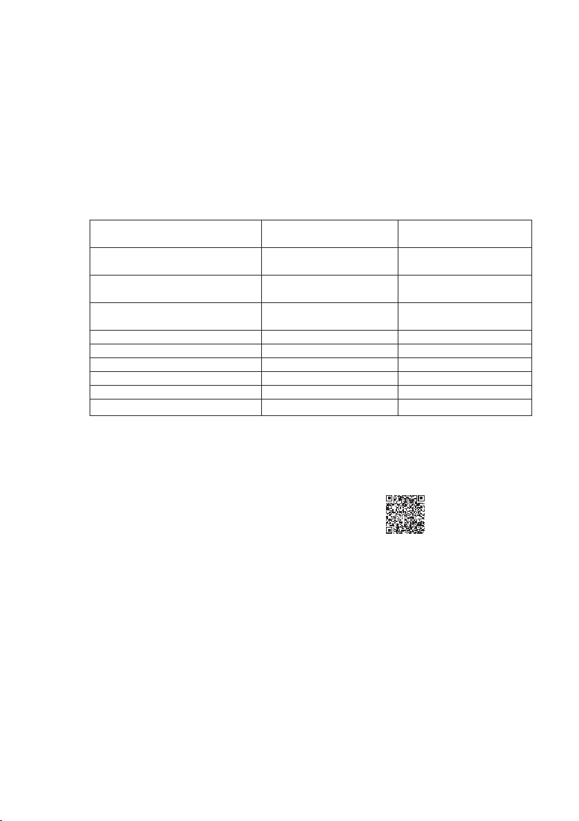
User’s Manual
Contents Document number Note
SA11 Smart Adapter
Start-up Manual IM 12A06S01-01Z1-(P) Attached to the product
SA11 Smart Adapter
User’s Manual (English version) IM 12A06S01-00EN-(P) Available for download
SA11 Smart Adapter
User’s Manual (Japanese version) IM 12A06S01-00JA-(P) Available for download
FLXA402 4-wire Analyzer
User’s Manual IM 12A01F01-02 Available for download
UM33A-S00 Digital Indicator IM 05P09D21-11EN Attached to the product
BA11 Active Junction Box IM 12B06W03-01E-E Attached to the product
WU11 Interconnection cable IM 12B06W02-03E-E Attached to the product
WE10 IM 12B06W02-02E-E Attached to the product
IB100 Interface Box IM 12B06J09-01E-E Available for download
Fieldmate IM 01R01A01-01E Available for download
The “E” or “EN” in the document number is the language code for English version, the “JA”
indicates the Japanese version and the “Z” indicates it is a multi-language document.
3
Downloads can be done from: https://www.YOKOGAWA.com/solutions/products-platforms/
process-analyzers/liquid-analyzers/#Downloads
You can use the QR-code for quick-access.
NOTE
• Please hand over the user’s manuals to your end users so that they can keep the user’s
manuals on hand for convenient reference.
• Please read the information thoroughly before using the product.
• The purpose of these user’s manuals is not to warrant that the product is well suited to
any particular purpose but rather to describe the functional details of the product.
• No part of the user’s manuals may be transferred or reproduced without prior written
consent from YOKOGAWA .
• YOKOGAWA reserves the right to make improvements in the user’s manuals and product
at any time, without notice or obligation.
• If you have any questions, or you find mistakes or omissions in the user’s manuals, please
contact our sales representative or your local distributor.
Drawing Conventions
Some drawings may be partially emphasized, simplified, or omitted, for the convenience of
description. Some screen images depicted in the user’s manual may have different display
positions or character types (e.g., the upper / lower case). Also note that some of the
images contained in this user’s manual are display examples.
IM 12A06S01-01EN-P
Page 4
4
2. Safety Precautions
2-1. Safety, Protection, and Modification of the Product
• In order to protect the system controlled by the product and the product itself and
ensure safe operation, observe the safety precautions described in this user’s manual.
YOKOGAWA Process Analyzers (simply referred to as YOKOGAWA) is not liability for
safety if users fail to observe these instructions when operating the product.
• If this instrument is used in a manner not specified in this user’s manual, the protection
provided by this instrument may be impaired.
• If any protection or safety circuit is required for the system controlled by the product or for
the product itself, prepares it separately.
• Be sure to use the spare parts approved by YOKOGAWA when replacing parts or
consumables.
• Modification of the product is strictly prohibited.
• The following safety symbols are used on the product as well as in this manual.
WARNING
This symbol indicates that an operator must follow the instructions laid out in this manual
in order to avoid the risks, for the human body, of injury, electric shock, or fatalities. The
manual describes what special care the operator must take to avoid such risks.
CAUTION
This symbol indicates that the operator must refer to the instructions in this manual in order
to prevent the instrument (hardware) or software from being damaged, or a system failure
from occurring.
CAUTION
This symbol gives information essential for understanding the operations and functions.
NOTE
This symbol indicates information that complements the present topic.
This symbol indicates Protective Ground Terminal.
This symbol indicates Function Ground Terminal. Do not use this terminal as the protective
ground terminal.
2-2. Warning and Disclaimer
The product is provided on an “as is” basis. YOKOGAWA shall have neither liability nor
responsibility to any person or entity with respect to any direct or indirect loss or damage
arising from using the product or any defect of the product that YOKOGAWA cannot
predict in advance.
IM 12A06S01-01EN-P
Page 5

2-3. SA11
• The SA11 should only be used with equipment that meets the relevant IEC, American,
Canadian, and Japanese standards. YOKOGAWA accepts no responsibility for the
misuse of this unit.
• The Instrument is packed carefully with shock absorbing materials, nevertheless, the
instrument may be damaged or broken if subjected to strong shock, such as if the
instrument is dropped. Handle with care.
CAUTION
Electrostatic discharge
The SA11 contains devices that can be damaged by electrostatic discharge.
When servicing this equipment, please observe proper procedures to prevent such damage.
CAUTION
Do not use an abrasive or organic solvent in cleaning the instrument.
CAUTION
This instrument is an EN61326-1 Class A product, and it is designed for use in the industrial
environment. Please use this instrument in the industrial environment only.
2-4. Product Disposal
The instrument should be disposed of in accordance with local and national legislation/
regulations.
2-5. Warranty and service
YOKOGAWA products and parts are guaranteed free from defects in workmanship and
material under normal use and service for a period of (typically) 12 months from the date of
shipment from the manufacturer.
5
Individual sales organizations can deviate from the typical warranty period, and the
conditions of sale relating to the original purchase order should be consulted. Damages
caused by wear and tear, inadequate maintenance, corrosion, or by the effects of chemical
processes are excluded from this warranty coverage.
In the event of warranty claim, the defective goods should be sent (freight paid) to the
service department of the relevant sales organization for replacement (at YOKOGAWA
discretion).
The following information must be included in the letter accompanying the returned goods:
• Part number, model code and serial number
• Original purchase order and date
• Length of time in service and a description of the process
• Description of the fault, and the circumstances of failure
• Process/environmental conditions that may be related to the failure of the device.
• A statement whether warranty or non-warranty service is requested
• Complete shipping and billing instructions for return of material, plus the name and phone
number of a contact person who can be reached for further information.
Returned goods that have been in contact with process fluids must be decontaminated /
disinfected before shipment. Goods should carry a certificate to this effect, for the health
IM 12A06S01-01EN-P
Page 6

6
and safety of our employees. Material safety data sheets should also be included for all
components of the processes to which the equipment has been exposed.
2-6. Copyright and Trademark Notices
The online manual is protected by the PDF security from modification; however, it can be
output via a printer. Printing out the online manual is only allowed for the purpose of using
the product.
When using the printed information of the online manual, check if the version is the most
recent one by referring to the version attached to the product. No part of the online manual
may be transferred, sold, distributed (including delivery via a commercial PC network or the
like), or registered or recorded on video tapes.
FLEXA, FLXA, SENCOM and FieldMate are trademarks or registered trademarks of
YOKOGAWA Electric Corporation. Adobe, Acrobat and Acrobat Reader are either
registered trademarks or trademarks of Adobe Systems Incorporated in the United States
and/or other countries.
All other company and product names mentioned in this user’s manual are trademarks
or registered trademarks of their respective companies. We do not use TM or ® mark to
indicate those trademarks or registered trademarks in this user’s manual.
2-7. SA11 fonts
(c) Copyright 2000-2001 /efont/ The Electronic Font Open Laboratory. All rights reserved.
Redistribution and use in source and binary forms, with or without modification, are
permitted provided that the following conditions are met:
1. Redistributions of source code must retain the above copyright notice, this list of
conditions and the following disclaimer.
2. Redistributions in binary form must reproduce the above copyright notice, this list of
conditions and the following disclaimer in the documentation and/or other materials
provided with the distribution.
3. Neither the name of the team nor the names of its contributors may be used to endorse
or promote products derived from this font without specific prior written permission.
THIS FONT IS PROVIDED BY THE TEAM AND CONTRIBUTORS “AS IS” AND ANY
EXPRESS OR IMPLIED WARRANTIES, INCLUDING, BUT NOT LIMITED TO, THE
IMPLIED WARRANTIES OF MERCHANTABILITY AND FITNESS FOR A PARTICULAR
PURPOSE ARE DISCLAIMED. IN NO EVENT SHALL THE TEAM OR CONTRIBUTORS
BE LIABLE FOR ANY DIRECT, INDIRECT, INCIDENTAL, SPECIAL, EXEMPLARY, OR
CONSEQUENTIAL DAMAGES (INCLUDING, BUT NOT LIMITED TO, PROCUREMENT OF
SUBSTITUTE GOODS OR SERVICES; LOSS OF USE, DATA, OR PROFITS; OR BUSINESS
INTERRUPTION) HOWEVER CAUSED AND ON ANY THEORY OF LIABILITY, WHETHER IN
CONTRACT, STRICT LIABILITY, OR TORT (INCLUDING NEGLIGENCE OR OTHERWISE)
ARISING IN ANY WAY OUT OF THE USE OF THIS FONT, EVEN IF ADVISED OF THE
POSSIBILITY OF SUCH DAMAGE.
IM 12A06S01-01EN-P
Page 7

3. CE marking products
3-1. Authorized Representative in EEA
The Authorized Representative for this product in EEA is YOKOGAWA Europe B.V.,
Euroweg 2, 3825 HD Amersfoort, The Netherlands.
3-2. Identification Tag
This manual and the identification tag attached on a packing box are essential parts of the
product. Keep them together in a safe place for future reference.
3-3. Users
This product is designed to be used by a person with specialized knowledge.
4. Introduction and general description
This Quick Start-up Manual describes how to use SA11 with YOKOGAWA ’s HOST
systems and sensors. Please read carefully this manual and the instruction manual of the
relevant HOST system and sensor before using this SA11 slave device.
4-1. Instrument check
Upon delivery, unpack the device carefully and inspect it to ensure that it was not damaged
during shipment. If damage is found, retain the original packing materials (including the
outer box) and then immediately notify the carrier and the relevant YOKOGAWA sales
office.
4-2. Checking the model and suffix code
Make sure the model and suffix code on the metallized label affixed to the device housing
are in line with the order.
7
NOTE
Be sure to apply correct power to the device, as detailed on the label in Figure 1.1.
Figure 1.1: Example of label SA11
IM 12A06S01-01EN-P
Page 8

8
4-3. Checking the accessories
Make sure that besides the SA11 device the accessories in Table 1.1 are included.
Options are available only if ordered.
Table 1.1: Accessories
Product Name Quantity Remark
SA11 Smart Adapter dust caps 2 pcs/device To prevent dust inside the connectors
Option: Universal mounting set 1 set Option code /UM*
Startup Manual 1 copy Quick startup description
QIS/QIC 1 copy Test certificate
*Option /UM contains Pipe and Wall mounting hardware
NOTE Be sure to remove the dust caps before using the device.
4-4. Regulatory Compliance
Safety: IEC 61010-1
EN61010-1
Category based on IEC 61010: I (Note 1)
Pollution degree based on IEC 61010: 2 (Note 2)
Note 1: Installation category, called over-voltage category, specifies impulse withstand
voltage. Equipment with “Category I” is used for connection to circuits in which
measures are taken to limit transient over-voltages to an appropriately low level.
Note 2: Pollution degree indicates the degree of existence of solid, liquid, gas or other
inclusions which may reduce dielectric strength.
EMC: EN61326-1 Class A, Table 2 (For use in industrial locations)
Influence of immunity environment (Criteria A): Output is within
accuracy
EN61326-2-3
AS/NZS CISPR 11
KC (registered as R-R-YPA-SA11)
RoHS2: EN 50581
Installation altitude: 2000 m or less
CAUTION
The device is packed carefully in a shock
absorbing box, nevertheless, the device may
be damaged or broken if subjected to strong
shock. Handle with care.
CAUTION
The device is a Class A product, and
it is designed for use in the industrial
environment. Please use this device in the
industrial environment only.
IM 12A06S01-01EN-P
WARNING
Do not use an abrasive or organic solvent in
cleaning the device.
WARNING
The SA11 contains components that can be
damaged by electrostatic discharge.
When servicing this device, please observe
proper procedures to prevent such damage.
Page 9

4-5. Model and suffix code
Model Suffix Option Description
code code code
SA11 SENCOM Smart Adapter
Measuring -P1 pH/ORP, conventional
Parameter -P2 pH/ORP, differential
-C1 Specific conductivity (SC)
Type -AA General purpose
Region -N Not specified
Connection type -VS Variopin connector for SENCOM ID-chip in sensor
Style -NN Always -NN
Option /UM Pipe and wall mounting hardware
4-6. Spare part list
Order no. Product Name Quantity Remark
K1548PQ Universal mounting set 1 set Option /UM
K1548GF O-ring set (5 pieces) 1 set
Option /UM contains Pipe and Wall mounting hardware
Figure 4.1 Positioning of O-ring
5. Wiring and installation
9
Modbus Host
max. 100m
(328ft)
e.g. FLXA402
WU11-M9-**-WP-S
WU11-M9-**-WP-S
Modbus S lave
SA11
max. 100m (328ft)
Suffix -C-AA-M9
Serial# N3T400171
Power +2.7. +5.5VDC/30mW
T amb. -20.. + 55ºC
IP Type 4X / IP66
ACTIVE JUNCTION BOX
BUS
IN OUT J1 J2 J3 J4
max. 100m
(328ft)
Modbus S lave
SA11
YPA Europe
Made in the Netherlands 3825HD-2
BA11
SENSOR CONNECTIONS
WU11-M9-**-CN-S
Read IM
12B06W03-01E-E
2018
Figure 5.1: Installation diagram SA11
5-1. Installation site
The SA11 is weatherproof and can be installed both inside and outside. Select an
installation site that meets the following conditions:
• Mechanical vibrations and shocks are negligible
• No relay switch and power switch are installed close to the device
• There is space mounting the device to the Yokogawa- sensor & Yokogawa HOST system
• Not exposed to direct sunlight or severe weather conditions
• Maintenance is possible
• No corrosive atmosphere
• Water Protection: IP67, NEMA Type 4X
IM 12A06S01-01EN-P
Page 10

10
5-2. Connecting to the sensor
Direct mounting
The SA11 can be installed directly on top of the YOKOGAWA labelled sensor by means
of the Variopin connection system. In this case the temperature limit of the device is
determined by the process temperature, limited from -30 up to +100°C / -22 up to +212°F
for power supply +2.7 to +4.5VDC, -30 up to +125°C / -22 up to +257°F for power supply
+4.5 to +5.5VDC.
Figure 5.2: Example of direct mounting of SA11 to sensor
CAUTION
Place the Variopin connectors securely to guarantee IP67.
Cable mounting
When there is less room to install the SA11 on top of the YOKOGAWA labelled sensor or
when the process conditions are higher than +100°C (for power supply +2.7 to +4.5VDC) or
+125ºC (for power supply +4.5 to +5.5VDC), an alternative mounting method is to install the
SA11 using the optional wall/pipe mounting hardware. The SA11 in this case is connected to
the sensor using the dedicated extension cable model WE10 with a fixed length of 3 meter.
The ambient temperature limit of the device has to be within -30 to +55°C.
Figure 5.3: Example of cable mounting of SA11 to sensor
CAUTION
Place the Variopin connectors securely to guarantee IP67.
NOTE
Use the correct Variopin cable. For correct measurement without loss of specification the
SA11-P1 must be used with WE10-H-D-003-V1, all other types must be used with WE10H-D-003-V2.
IM 12A06S01-01EN-P
Page 11

11
5-3. Wiring to the HOST system
Wired connection
The YOKOGAWA HOST system is connected to the SA11 using the WU11 type S
interconnection cable with at one end wired terminals and on the other end a M9 connector.
This cable is specified for reliable transfer of digital signals, and especially designed to
be installed in a heavy industrial environment. The double shielded cable will protect the
connected devices for interference from high voltages and currents which are present on other
cables. The cable is specified to be used in IP67 applications, allowing it to be submerged as
a whole. The WU11 type S cable is available length up to a maximum of 100 meter (328ft).
Connection concept
The YOKOGAWA HOST system model FLXA402 can be connected to maximum five SA11
devices. In case of more than two SA11 devices connected, the BA11 Active Junction Box
must be used. Connection in between the FLXA402 and BA11 is done by using the WU11
type -S interconnection cable with at one end wired terminals and on the other end a M9
connector. Connection in between the BA11 and the SA11 is done using the WU11 type -S
interconnection cable with at both ends a M9 connector. In both cases the maximum length
has to be within 100 meter (328ft).
Wireless connection
In laboratory environments the HOST Fieldmate system can be connected to the SA11
using the YOKOGAWA Bluetooth device model IB100. Interconnection in between the
IB100 and SA11 is done using the WU11 type -S interconnection cable with at both ends a
M9 connector. The wireless communication in between the Fieldmate system and IB100 is
limited to a distance of 10 meter.
Grounding
The measuring system must always be
connected to a class D ground (a ground
resistance of 100 Ohm or less), preferably
done at the HOST side. To protect the
SA11 device against interference, such as
electromagnetic noise or common mode, all
wires in WU11 type -S cable are connected
at HOST. This makes the housing of the
SA11 grounded. For correct measurement
without loss of specifications, it is strongly
recommended to ensure that the process
liquid is grounded. Figure 5.4 shows the
connection diagram in case without/UM
option.
WU11
(max 100m)
SA11
Sensor
Liquid
Ground 2
Figure 5.4: Typical installation of
SA11 to host
Host
Ground 1
However, in case that there is different potential between Ground at HOST side and Ground
which the housing of the SA11 is connected, figure 5.5 shows the example of the installation.
To prevent ground loop by this different potentials it is necessary to disconnect one of the
ground references. This can be done at the HOST side by disconnecting the wire #82 of the
WU11 type S cable. Please connect #82 to NC terminal on the SENCOM SA module when
SA11 is connected to FLXA402. Please be sure to insulate contact pin of #82 wire from
terminals and metal housing, when SA11 is connected to other host. The SA11 device must
then be installed using the optional pipe and wall mounting hardware (/UM) with a ground wire
IM 12A06S01-01EN-P
Page 12

connected in between the ground terminal
Yokogawa has an extensive sales and
distribution network.
Please refer to the European website
(www.yokogawa.com/eu) to contact your
nearest representative.
YOKOGAWA EUROPE BV
Euroweg 2
3825 HD AMERSFOORT
The Netherlands
www.yokogawa.com/eu
YOKOGAWA ELECTRIC CORPORATION
World Headquarters
9-32, Nakacho 2-chome, Musashino-shi
Tokyo 180-8750
Japan
www.yokogawa.com
YOKOGAWA CORPORATION OF AMERICA
2 Dart Road
Newnan GA 30265
USA
www.yokogawa.com/us
YOKOGAWA ELECTRIC ASIA Pte. LTD.
5 Bedok South Road
Singapore 469270
Singapore
www.yokogawa.com/sg
YOKOGAWA CHINA CO. LTD.
3F Tower D Cartelo Crocodile Building
No.568 West Tianshan Road Changing District
Shanghai, China
www.yokogawa.com/cn
YOKOGAWA MIDDLE EAST B.S.C.(c)
P.O. Box 10070, Manama
Building 577, Road 2516, Busaiteen 225
Muharraq, Bahrain
www.yokogawa.com/bh
Host
of the mounting bracket and the ground
reference of the process.
Alternate way to prevent ground loop is
to isolate the SA11 & mounting plate from
ground 2 & keep the terminal 82 connected.
Remark: For the installation shown in Figure
5.5, in case the ground references at the
HOST side (Ground 1) and process side
SA11/UM
WE10
(max 3m)
Sensor
Liquid
WU11
(max 100m)
#82
(Ground 2) have no potential difference the
shield wire of the WU11 type -S cable (wire
#82) can stay connected to the (pre-defined)
ground terminal at the HOST.
Ground 2
Figure 5.5: Typical installation example
Ground 1
to prevent ground loop
In combination with Host who does not have
grouding terminal to still meet the statutory
Host
IB100
regulations it is necessary to ground either
the SA11 enclosure (e.g. by using the option
/UM) or ground the shield of the cable. An
example is shown in figure 5.6.
SA11/UM
WE10
(max 3m)
Sensor
Liquid
WU11
(max 10m)
Ground
Figure 5.6: Installation example
SA11 & IB100 to prevent interference
Operation
Select a YOKOGAWA parameter specific sensor equipped with an ID-chip which is suitable
for the process. When all wiring is completed, turn on the power of the HOST system. Part
of the setup of the SA11 will be done automatically by reading the content of the ID-chip of
the sensor. These are sensor characteristics, factory calibration data, customer calibration
data, diagnostics and loggings of calibration and events. For details refer to the SA11 Smart
Adapter User’s Manual. Other setups have to be done by the YOKOGAWA HOST system,
for details see the belonging User’s Manual. If the system is configured incorrectly, an error
indicator may be displayed, or the measurement values displayed may be incorrect. Refer to
the User Manual of the HOST system how to check the initial settings and change them to
suit your purpose.
IM 12A0601-01EN P Printed in The Netherlands, 02-1906
Subject to change without notice
Copyright ©
 Loading...