

YOKOGAWA Rotamass Intense, Rotamass series, Rotamass Hygienic, Rotamass Supreme, Rotamass Giga General Instruction Manual
...Page 1

User's Manual
IM 01U10B00-00EN-R
IM 01U10B00-00EN-R, 3rd edition, 2018-07-09
ROTA
MASS
Total Insight
Coriolis Mass Flow and Density Meter
General Instruction Manual
Page 2

Table of contents
2 / 90
IM 01U10B00-00EN-R, 3rd edition, 2018-07-09
Table of contents
1 Introduction................................................................................................................................................ 4
1.1 Scope of application ......................................................................................................................... 4
1.2 Target group ..................................................................................................................................... 4
1.3 Applicable documents....................................................................................................................... 4
1.4 Explanation of safety instructions and symbols................................................................................ 5
2 Safety.......................................................................................................................................................... 6
2.1 Intended use..................................................................................................................................... 6
2.2 Technical conditions ......................................................................................................................... 6
2.3 General safety instructions ............................................................................................................... 7
3 Warranty ..................................................................................................................................................... 9
4 Product specification ................................................................................................................................ 10
4.1 Scope of delivery .............................................................................................................................. 10
4.2 Measuring principle and flow meter design ...................................................................................... 11
4.2.1 Measuring principle.............................................................................................................. 11
4.2.2 Flow meter ........................................................................................................................... 13
4.3 Identification...................................................................................................................................... 14
4.3.1 Nameplates.......................................................................................................................... 14
4.3.2 Model code .......................................................................................................................... 17
4.4 Flow meter components ................................................................................................................... 17
4.5 Mechanical specification................................................................................................................... 18
5 Transport and storage .............................................................................................................................. 19
5.1 Transport .......................................................................................................................................... 19
5.2 Storage ............................................................................................................................................. 20
6 Installation.................................................................................................................................................. 21
6.1 Installation instructions ..................................................................................................................... 21
6.1.1 Installation dimensions......................................................................................................... 21
6.1.2 Installation site ..................................................................................................................... 21
6.1.3 Instructions........................................................................................................................... 22
6.1.4 Installation position .............................................................................................................. 23
6.1.5 Sanitary Installation.............................................................................................................. 24
6.2 Installation instructions ..................................................................................................................... 26
6.3 Sensor installation ............................................................................................................................ 27
6.3.1 General installation rules ..................................................................................................... 27
6.3.2 Installation in pipe ................................................................................................................ 28
6.3.3 Installation Rotamass Nano (Option PD) ............................................................................. 30
6.3.4 Installation recommendation for viscosity measurements ................................................... 31
6.4 Insulation and heat tracing................................................................................................................ 32
6.4.1 Heat tracing.......................................................................................................................... 32
6.4.2 Customer-supplied insulation............................................................................................... 32
6.5 Transmitter installation...................................................................................................................... 33
6.5.1 Rotating and replacing the display....................................................................................... 33
6.5.2 Rotating transmitter housing (integral type) ......................................................................... 36
6.5.3 Rotating the terminal box (remote type)............................................................................... 38
6.5.4 Installing transmitter on pipe (remote type).......................................................................... 39
Page 3

Table of contents
2018-07-09IM 01U10B00-00EN-R, 3rd edition, 2018-07-09
3 / 90
6.6 Installation check list......................................................................................................................... 41
7 Wiring ......................................................................................................................................................... 42
7.1 General wiring rules.......................................................................................................................... 42
7.2 Grounding connections and sensor circuits...................................................................................... 44
7.3 Connecting cable installation............................................................................................................ 45
7.3.1 Connection terminals ........................................................................................................... 46
7.3.2 Connecting the connecting cable to sensor ......................................................................... 49
7.3.3 Connecting the connecting cable to transmitter................................................................... 50
7.4 Transmitter........................................................................................................................................ 51
7.4.1 Connection terminals ........................................................................................................... 51
7.4.2 HART communication .......................................................................................................... 52
7.4.3 MODBUS communication .................................................................................................... 52
7.4.4 Assignment of inputs and outputs........................................................................................ 53
7.4.5 Output signals ...................................................................................................................... 55
7.4.6 Input signals......................................................................................................................... 61
7.4.7 Power supply ....................................................................................................................... 62
7.4.8 Connecting power supply and external devices................................................................... 63
7.5 Wiring check list................................................................................................................................ 66
8 Commissioning.......................................................................................................................................... 67
9 System configuration and operation ....................................................................................................... 68
9.1 Operating options ............................................................................................................................. 68
9.2 Display.............................................................................................................................................. 68
9.3 Default settings................................................................................................................................. 72
9.3.1 Setting display language...................................................................................................... 72
9.3.2 Setting date.......................................................................................................................... 73
9.3.3 Setting time .......................................................................................................................... 73
9.3.4 Setting zero point ................................................................................................................. 74
9.3.5 Performing autozero ............................................................................................................ 74
9.4 Advanced settings ............................................................................................................................ 75
9.4.1 Setting hardware write-protection ........................................................................................ 75
9.4.2 MODBUS hardware setting.................................................................................................. 77
10 Troubleshooting ........................................................................................................................................ 80
10.1 Malfunction of operation ................................................................................................................... 80
10.2 Zero point unstable ........................................................................................................................... 81
10.3 Display deviating............................................................................................................................... 82
11 Maintenance and repair ............................................................................................................................ 84
11.1 Exterior cleaning ............................................................................................................................... 85
11.2 Recalibration and calibration service ................................................................................................ 85
11.3 Impairment of the display.................................................................................................................. 85
11.4 List of replacement parts .................................................................................................................. 85
12 Dismantling and disposal ......................................................................................................................... 86
12.1 Decontamination and return shipment .............................................................................................. 86
12.2 Disposal ............................................................................................................................................ 86
13 Specifications ............................................................................................................................................ 88
13.1 Ambient conditions ........................................................................................................................... 88
Page 4

General Instruction Manual
Introduction
Scope of application
4 / 90
IM 01U10B00-00EN-R, 3rd edition, 2018-07-09
1 Introduction
1.1 Scope of application
These instructions apply to the following Rotamass Total Insight product families:
▪ Rotamass Nano
▪ Rotamass Supreme
▪ Rotamass Giga
▪ Rotamass Prime
▪ Rotamass Intense
▪ Rotamass Hygienic
▪ Rotamass Total Insight transmitter in combination with any Rotamass Total Insight
sensor.
1.2 Target group
The following persons are the target group of this manual:
▪ Technicians
▪ Engineers
This manual along with its applicable documents enable the target group to complete the
following steps:
▪ Installation
▪ Commissioning
▪ Configuration (parametrization)
▪ Integration of the flow meter into a process control system
▪ Troubleshooting
▪ Maintenance and repair
▪ Dismantling and disposal
1.3 Applicable documents
The following documents supplement this manual:
▪ Explosion Proof Type Manual (Ex-IM) IM01U10X␣␣-00␣␣-R
▪ Software Instruction Manual (SW-IM) IM01U10S␣␣-00␣␣-R
▪ General Specifications (GS) GS01U10B␣␣-00␣␣-R
Page 5
Explanation of safety instructions and symbols
General Instruction Manual
Introduction
IM 01U10B00-00EN-R, 3rd edition, 2018-07-09
5 / 90
1.4 Explanation of safety instructions and symbols
Signal words
Warning notices are intended to alert users to potential hazards when working with the
flow meter. There are four hazard levels that can be identified by the signal word:
Signal word Meaning
DANGER
Identifies a high-risk hazard resulting in death or severe injury
unless avoided.
WARNING
Identifies a fluid-risk hazard that may lead to death or severe injury unless avoided.
CAUTION
Identifies a low-risk hazard that may lead to minor or moderate
injury unless avoided.
NOTICE Identifies a hazard resulting in property damage.
Explanation of
symbols
Symbols in this
document
Meaning
Indicates a hazard, documentations must be consulted.
Indicates important information.
IM01U10S01-00␣␣-R
The ␣␣ symbols in the document numbers are placeholders,
here, for example, for the corresponding language version (DE,
EN, etc.).
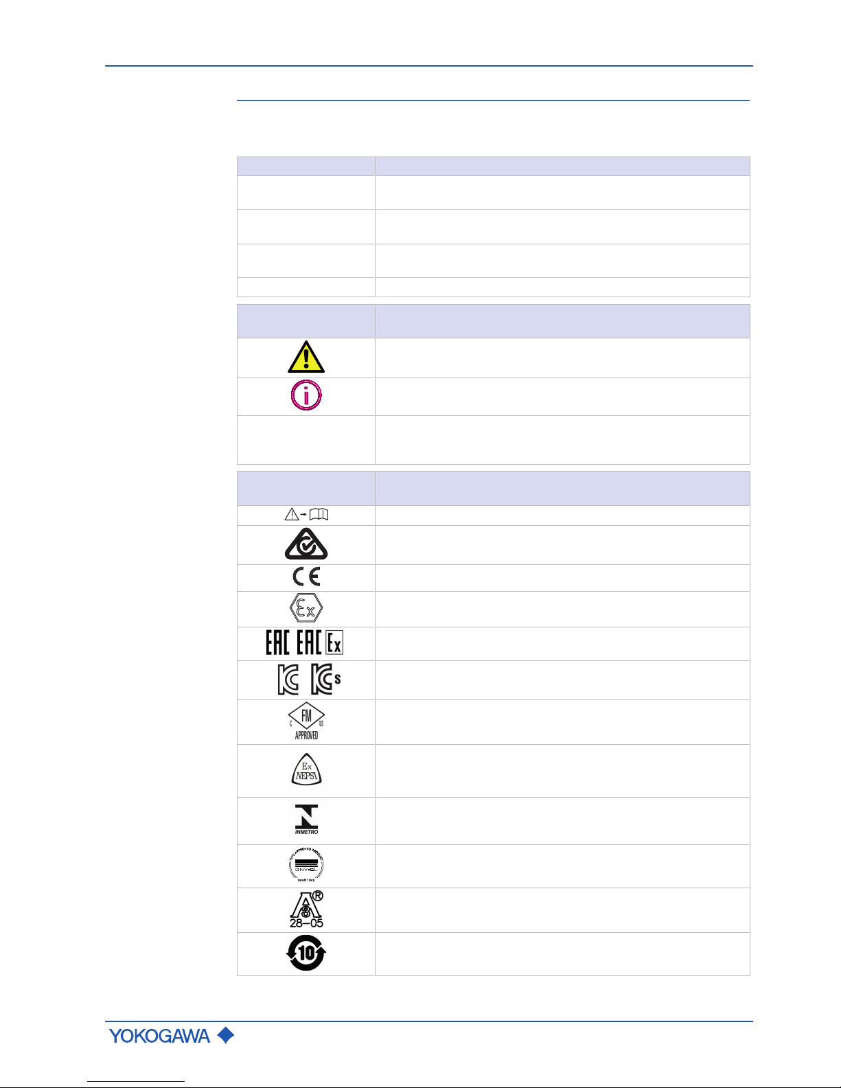
Symbols on the
nameplates
Meaning
Warning that requires reading the documentation
RCM marking
CE marking
ATEX explosion protection marking
,
EAC and EAC Ex marking
,
Korean (KC and KCs) marking
FM/CSA marking
NEPSI marking
INMETRO marking
DNV GL type approval marking
3-A Sanitary approval marking
China RoHS marking
Page 6

General Instruction Manual
Safety
Intended use
6 / 90
IM 01U10B00-00EN-R, 3rd edition, 2018-07-09
2 Safety
2.1 Intended use
The flow meter described in this user's manual is intended to measure mass flow of fluids
and gases while simultaneously also capturing their density and temperature. These values form the basis for calculating additional measured quantities, such as volume flow
and concentration of fluids.
The flow meter uses the Coriolis principle (see Measuring principle [}11]) and can be
used in process automation for a wide range of flow rate measurements. It allows for
measuring various fluids, e.g.:
▪ Oils, grease
▪ Gases, liquid gases
▪ Acids, solutions, solvents
▪ Emulsions and suspensions
Use of the flow meter is limited primarily by the necessary homogeneity of the fluid and
chemical resistance of the wetted parts. Details can be obtained from the responsible
Yokogawa sales organization. Operational safety cannot be ensured in the event of any
improper or not intended use. Rota Yokogawa is not liable for damage arising from such
use.
The flow meter described in this user’s manual is a class A device according to
EN 61326-1 and may only be used in an industrial environment.
2.2 Technical conditions
At normal conditions, the flow meter does not release any poisonous gases or substances.
If the flow meter is operated in faulty conditions, its safety and function may be impaired.
For this reason, the following must be observed:
▶ Operate the flow meter only when in good working order.
▶ If its operational performance changes unexpectedly, check flow meter for faults.
▶ Do not undertake unauthorized conversions or modifications on the flow meter.
▶ Eliminate faults immediately.
▶ Use only original spare parts.
Page 7

General safety instructions
General Instruction Manual
Safety
IM 01U10B00-00EN-R, 3rd edition, 2018-07-09
7 / 90
2.3 General safety instructions
DANGER
Use of fluids that are a health hazard may result in caustic burns or
poisoning
▶ When removing the flow meter, avoid touching the fluid and breathing gas residues
left in the sensor.
▶ Wear protective clothing and a breathing mask.
DANGER
Use of unproper materials through the customer may result in heavy corrosion and/or erosion
▶ The medium temperature / pressure ranges are calculated and approved without cor-
rosion or erosion.
▶ The customer is fully responsible to select proper materials to withstand his corrosive
or erosive conditions.
▶ In case of heavy corrosion and/or erosion the instrument may not withstand the pres-
sure and an incident may happen with human and / or environmental harm.
▶ Yokogawa will not take any liability regarding damage caused by corrosion / erosion.
▶ If corrosion / erosion may happen, the user has to check periodically if the necessary
wall thickness is still in place.
WARNING
High fluid temperatures may result in hot surfaces and therefore a risk of
burns
▶ Apply thermal insulation to sensor.
▶ Attach warning labels to the sensor.
▶ Wear protective gloves.
WARNING
Risk of injury from electrical shock due to inadequate clothing
▶ Wear protective clothing as required by regulations.
WARNING
Risk of injury from electrical shock at the transmitter
▶ Avoid handling the transmitter with wet hands.
▶ Wear protective gloves.
The following basic safety instructions must be observed when handling the flow meter:
▶ Carefully read the user's manual prior to operating the flow meter.
▶ When using the flow meter in areas at risk of explosion, compliance with the Explo-
sion Proof Type Manual is mandatory.
▶ Only qualified specialist personnel must be charged with the tasks described in this
user's manual.
▶ Ensure that personnel complies with locally applicable regulations and rules for work-
ing safely.
▶ Do not remove or cover safety markings and nameplates from flow meter.
▶ Replace soiled or damaged safety markings on the flow meter. For replacing please
contact the Yokogawa Service Center.
▶ If Rotamass Total Insight is used to measure safety-related quantities, ensure that the
transmitter does not display any error messages and, if applicable, the total health
check function is performed at regular intervals (see applicable General Specifications GS01U01B␣␣-00␣␣-R, chapter "Options").
Page 8

General Instruction Manual
Safety
General safety instructions
8 / 90
IM 01U10B00-00EN-R, 3rd edition, 2018-07-09
▶ Avoid erosion and corrosion as they reduce accuracy and resistance to temperature
and pressure. Over time, calibration constants change as a result of erosion and corrosion, therefore requiring recalibration. Rota Yokogawa does not assume any guaranty or liability with respect to corrosion resistance of wetted parts in any specific
process. The user is responsible for selecting the appropriate materials. Rota Yokogawa provides support in clearing up the question of corrosion resistance of the materials used (special fluids but also cleaning agents). Minor changes in temperature,
concentration or pollution degree in the process may result in differences in terms of
corrosion resistance. In case of corrosion or erosion, the pipes must be checked periodically to ensure necessary wall thickness. This can be accomplished by using, for
example, the tube health check function (see applicable General Specifications
GS01U01B␣␣-00␣␣-R, chapter "Options").
▶ When performing welding tasks on the pipe, it is important not to ground the welding
equipment by way of the flow meter. Soldering and welding work on parts of the flow
meter is prohibited.
▶ Continuous temperature fluctuations in excess of 100 °C may result in tube failure
due to material fatigue and therefore must be avoided.
▶ The operator is responsible for ensuring that design limits (pressure, temperature) are
not exceeded in the event unstable fluids decay.
▶ External influences may result in failure of threaded connections. The operator is re-
sponsible for providing suitable protective measures.
▶ Compression and shock waves in pipes can cause damage to the sensor. For this
reason it is important to avoid exceeding the design limits (pressure, temperature).
▶ Fires may result in increased process pressure (caused by temperature-related vol-
ume changes) and failure of gaskets. The operator is responsible for taking suitable
measures to prevent fire-related damage.
▶ Manufacturing methods and technologies have been successfully field-tested for
decades. Erosion and/or corrosion are not taken into account.
▶ Removal of material from the flow meter with power tools such as drills or saws is not
permitted.
▶ Any repair, modification, replacement or installation of replacement parts is permitted
only so long as it is in keeping with this user's manual. Other work must be first authorized by Rota Yokogawa. Rota Yokogawa does not assume liability for damage
caused by unauthorized work on the flow meter or by improper use.
Page 9

General Instruction Manual
Warranty
IM 01U10B00-00EN-R, 3rd edition, 2018-07-09
9 / 90
3 Warranty
Please contact the Yokogawa sales organization if the device needs to be repaired.
The warranty terms for this device are described in the quotation.
If a defect for which Yokogawa is responsible occurs in the device during the warranty
period, Yokogawa will repair that defect at its own cost.
If you believe that the device is defective, please contact us and provide a detailed description of the problem. Please also tell us how long the defect has already occurred and
list the model code and serial number. Additional information, such as drawings, simplifies the identification of the cause and repair of the defect.
Based on our test results, we determine whether the device can be repaired at Yokogawa’s expense or at the expense of the customer. If, for example, the Yokogawa calibration device for the water flow rate confirms a deviation of the output signal from the
stated flow rate accuracy of the device, the device is deemed defective.
The warranty does not apply in the following cases:
▪ If the adhesion, blockage, deposit, abrasion or corrosion is the result of the device’s
actual use.
▪ If the device is mechanically damaged through solids in the fluid, hydraulic shock, or
similar influences.
▪ If the instructions in the corresponding General Specifications or user's manual that
must be met have not been followed.
▪ In case of problems, errors or damage that result from unprofessional installation by
the customer, for example due to insufficient tightness of the pipe fittings.
▪ In case of problems, errors or damage that result from operation, handling or storage
in rough ambient conditions that are beyond the specifications of the device.
▪ In case of problems, errors or damage that result from unprofessional or insufficient
maintenance by the customer, for example, if water or foreign particles enter the device due to opening the device cover.
▪ In case of problems, errors or damage that result from use or from performing mainte-
nance work on the device in a location other than the installation location specified by
Yokogawa.
▪ In case of problems, errors or damage that result from modification or repair work that
was not performed by Yokogawa or by a person authorized by Yokogawa.
▪ In case of problems, errors or damage that result from unprofessional installation, if
the location of the device has been changed.
▪ In case of problems, errors or damage that result from external factors, such as other
devices that are connected to this device.
▪ In case of problems, errors or damage that result from catastrophic external influ-
ences, such as fire, earthquake, storm, flooding or lightning.
Page 10

General Instruction Manual
Product specification
Scope of delivery
10 / 90
IM 01U10B00-00EN-R, 3rd edition, 2018-07-09
4 Product specification
4.1 Scope of delivery
The scope of delivery of the flow meter must be checked for completeness using the following list:
Integral type Remote type
Sensor
1 unit
1 unit
Transmitter 1 unit
Connecting cable -
Length accord-
ing to model
code
Operating tool for terminals 2 units 2 units
2-inch pipe mounting bracket set
▪ Sheet metal console (bracket)
▪ Mounting bracket (U-bracket)
▪ Fixing materials (2 nuts, 2 washers, 4 Allen
screws)
- 1 set
Pipe installation set for sensor (with device option PD)
▪ Sheet metal console (bracket)
▪ Mounting bracket (U-bracket)
▪ Fixing plate
▪ Fixing materials (14 nuts, 6 washers, 4 bolts, 8
notched washers, 4 rubber buffers)
- 1 set
Cable glands are included for a device with metric
cable entries and without Ex approval.
Please note:
▪ No cable glands are included for a device with
cable entries other than metric.
▪ For a device with Ex approval the inclusion of ca-
ble glands may vary. Please refer to the applicable
Explosion Proof Type Manual.
2 units 2 units
Cable glands for connecting cable between sensor
and transmitter, metal (pre-installed)
- 2 units
Termination kit for shortening the connecting cable
(not with option L000 or Y000), including instruction
booklet.)
- 1 set
Document folder with this content:
▪ Product CD/DVD (includes the complete product
documentation)
▪ Quick reference guide
▪ Safety Regulations Manual
▪ Further documents like certificates (depending on
model code)
1 folder 1 folder
Page 11
Measuring principle and flow meter design
General Instruction Manual
Product specification
IM 01U10B00-00EN-R, 3rd edition, 2018-07-09
11 / 90
4.2 Measuring principle and flow meter design
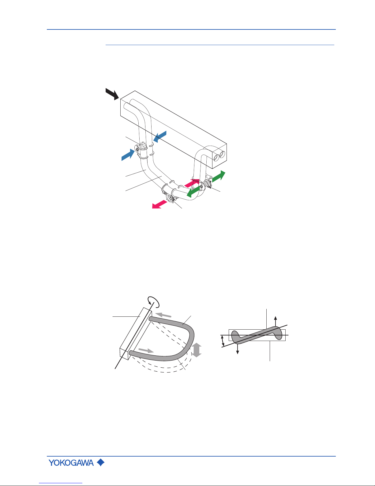
4.2.1 Measuring principle
The measuring principle is based on the generation of Coriolis forces. For this purpose, a
driver system (E) excites the two measuring tubes (M1, M2) in their first resonance frequency. Both pipes vibrate inversely phased, similar to a resonating tuning fork.
A
E
F1
S1
S2
F2
M1
Q
M2
-F1
-F2
-A
inlet
outlet
Fig.1: Coriolis principle
M1,M2 Measuring tubes E Driver system
S1, S2 Pick-offs A Direction of measuring tube
vibration
F1, F2 Coriolis forces Q Direction of fluid flow
Mass flow
The fluid flow through the vibrating measuring tubes generates Coriolis forces (F1, -F1
and F2, -F2) that produce positive or negative values for the tubes on the inflow or outflow side. These forces are directly proportional to the mass flow and result in deformation (torsion) of the measuring tubes.
1
3
1
2
3
A
E
A
E
F1
F2
α
Fig.2: Coriolis forces and measuring tube deformation
1 Measuring tube mount A
E
Rotational axis
2 Fluid F1, F2 Coriolis forces
3 Measuring tube α Torsion angle
Page 12
General Instruction Manual
Product specification
Measuring principle and flow meter design
12 / 90
IM 01U10B00-00EN-R, 3rd edition, 2018-07-09
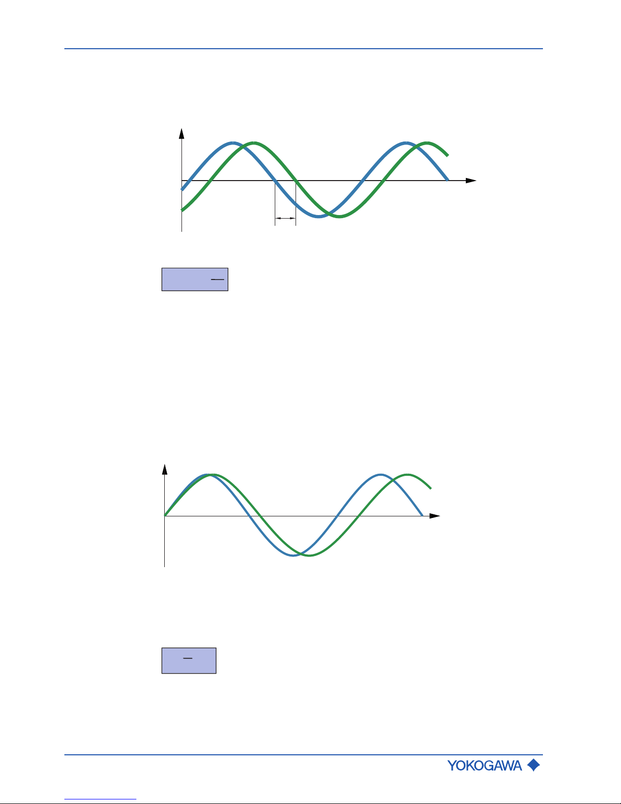
The small deformation overlying the fundamental vibration is recorded by means of pickoffs (S1, S2) attached at suitable measuring tube locations. The resulting phase shift Δ
φ
between the output signals of pick-offs S1 and S2 is proportional to the mass flow. The
output signals generated are further processed in a transmitter.
Δφ
S1
S2
y
t
Fig.3: Phase shift between output signals of S1 and S2 pick-offs
Δφ ~ FC ~
dt
dm
Δ
φ
Phase shift
m Dynamic mass
t Time
dm/dt Mass flow
F
c
Coriolis force
Density
measurement
Using a driver and an electronic regulator, the measuring tubes are operated in their resonance frequency ƒ. This resonance frequency is a function of measuring tube geometry,
material properties and the mass of the fluid covibrating in the measuring tubes. Altering
the density and the attendant mass will alter the resonance frequency. The transmitter
measures the resonance frequency and calculates density from it according to the formula below. Device-dependent constants are determined individually during calibration.
A
t
ƒ
2
ƒ
1
Fig.4: Resonance frequency of measuring tubes
A Measuring tube displacement
ƒ
1
Resonance frequency with fluid 1
ƒ
2
Resonance frequency with fluid 2
ρ = + ß
ƒ
2
α
ρ
Fluid density
ƒ
Resonance frequency of measuring tubes
α, β
Device-dependent constants
Page 13
Measuring principle and flow meter design
General Instruction Manual
Product specification
IM 01U10B00-00EN-R, 3rd edition, 2018-07-09
13 / 90
Temperature
measurement
The measuring tube temperature is measured in order to compensate for the effects of
temperature on the flow meter. This temperature approximately equals the fluid temperature and is made available as a measured quantity at the transmitter as well.
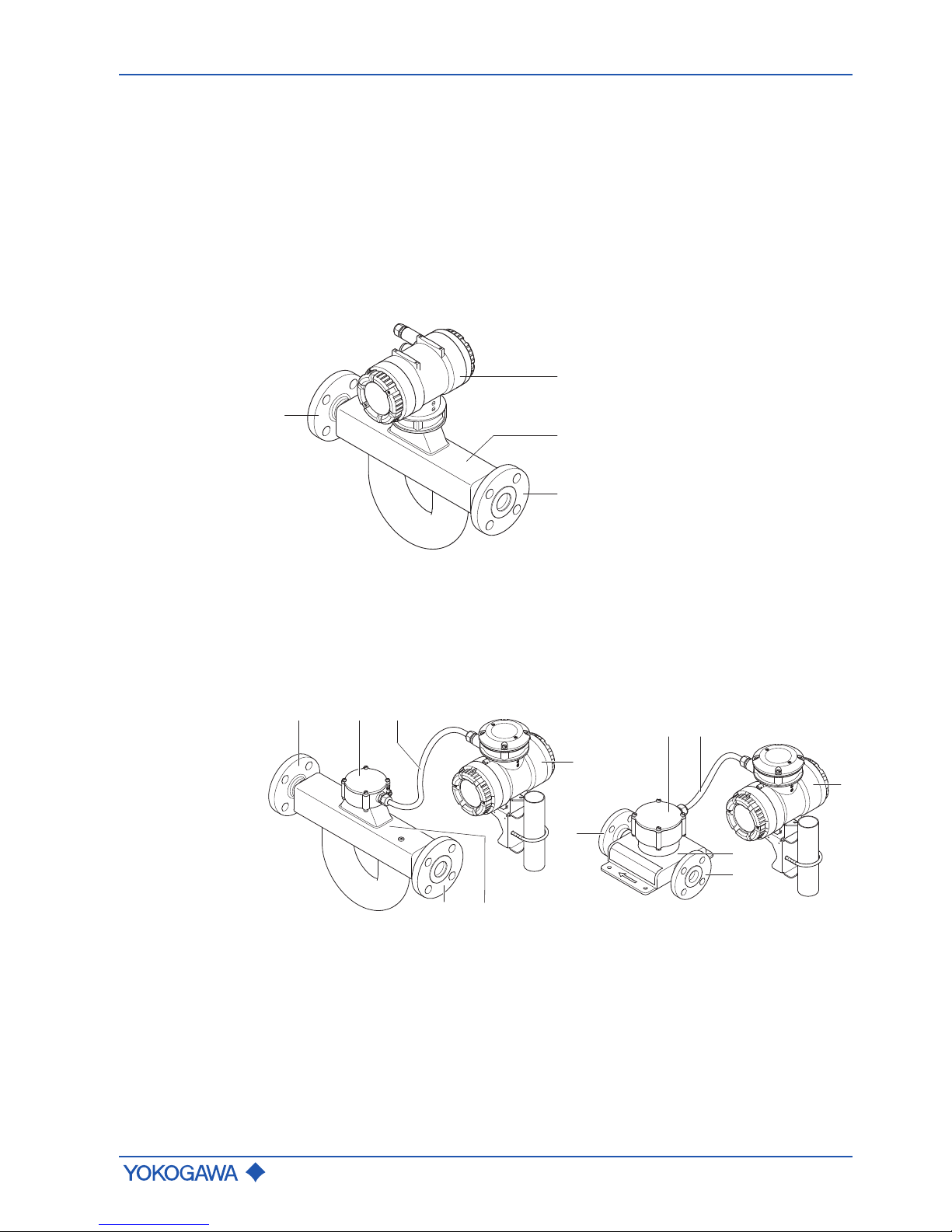
4.2.2 Flow meter
The Rotamass Total Insight Coriolis mass flow and density meter is offered in several
families (Nano, Supreme, Giga, Prime, Intense and Hygienic). It consists of the following
main components:
▪ Sensor
▪ Transmitter
In the integral type, sensor and transmitter are firmly connected.
1
2
3
3
Fig.5: Design of the Rotamass Total Insight integral type (Rotamass Supreme as an example)
1 Transmitter
2 Sensor
3 Process connections
When the remote type is used, sensors and transmitters are linked via connecting cable.
As a result, sensor and transmitter can be installed in different locations.
4 53
1
23
5
3
2
1
4
3
Fig.6: Design of the Rotamass Total Insight remote type (left: Rotamass Supreme, right: Rotamass
Nano)
1 Transmitter 4 Sensor terminal box
2 Sensor 5 Connecting cable
3 Process connections
Page 14
General Instruction Manual
Product specification
Identification
14 / 90
IM 01U10B00-00EN-R, 3rd edition, 2018-07-09
General
specifications
All available properties of the Rotamass Total Insight Coriolis mass flow and density meter are specified by means of a model code.
The position of the model code relevant to the respective property is depicted and highlighted in blue.
U S 36 40H BA1 0 2 C5 A NN00 2 JA 1
P8
- - -
- /-
RC
1 2 3 4 6 75 9 10 11 12 13 14 158
Fig.7: Example of an model code
A complete description of the model code is included in the General Specifications (GS)
of the corresponding product family.
4.3 Identification
The model code can be used to identify the flow meter along with its specification. The
model code is located on each main nameplate.
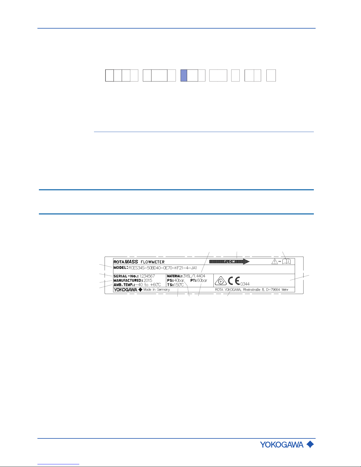
4.3.1 Nameplates
The sensor as well as the transmitter each contain a main nameplate and an additional
nameplate that feature different information.
NOTICE
For individual applications (e.g. marine applications with option MC␣) additional limitations to those on the nameplate may apply according to the respective applicable regulations.
The variants of the nameplates are described below.
Sensor
Main sensor
nameplate
1
5
4
3
2
6
7
11
10
9
8
12
1 Model code 7 Warning that requires reading the
documentation
2 Serial number 8 Area for conformity marking
3 Year of manufacture 9 Manufacturer's address
4 Ambient temperature range 10 Test pressure
5 Kind of material 11 Maximum allowed working pres-
sure at room temperature
6 Direction of flow 12 Maximum allowed process temper-
ature
Page 15
Identification
General Instruction Manual
Product specification
IM 01U10B00-00EN-R, 3rd edition, 2018-07-09
15 / 90
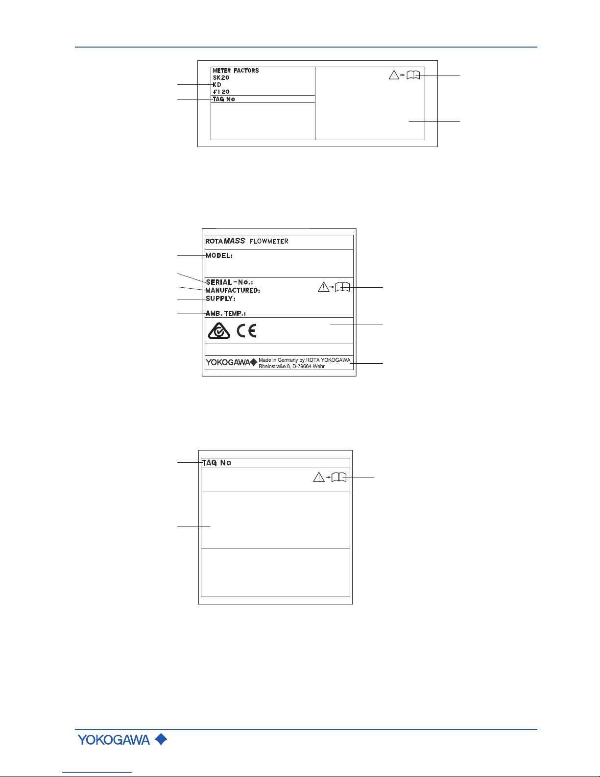
Additional sensor
nameplate
i
3
4
1
2
35
16.8
144
1 Calibration constants of sensor 3 Warning that requires reading the
documentation
2 Customer-Device location
identification (option BG)
4 Space for Ex marking (see Explo-
sion Proof Type Manual)
Transmitter
Main transmitter
nameplate
8
1
2
3
4
5
6
7
i
RCES34S-50BD40-OE70- -4-JA1
1234567
2015
24VAC or 100...240VAC, 50/60Hz
24VDC or 100...120VDC; 10W
-40...+60 oC
1 Model code 5 Ambient temperature range
2 Serial number 6 Warning that requires reading the
documentation
3 Year of manufacture 7 Area for conformity marking
4 Power supply range 8 Manufacturer's address
Additional
transmitter
nameplate
i
3
2
1
1 Customer-Device location identification (option BG)
2 Space for Ex marking (see Explosion Proof Type Manual)
3 Warning that requires reading the documentation
Page 16
General Instruction Manual
Product specification
Identification
16 / 90
IM 01U10B00-00EN-R, 3rd edition, 2018-07-09
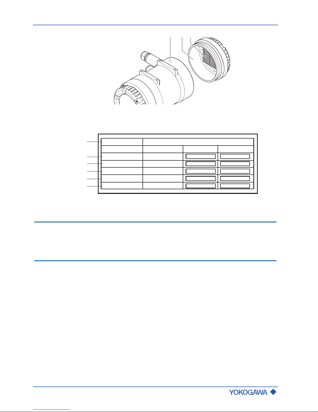
Label transmitter
3
1 2
1 Transmitter
2 Transmitter back cover
3 Label
SERIAL No.:
CPU FW :
DSP FW :
HMI FW :
HW :
Date :
Ex works:
D1xxxxxxxx
xx.xx.xx
xx.xx.xx
xx.xx.xx
xx.xx.xx
2016-03-15
Update 1: Update 2:
1
2
3
4
5
6
1 Serial number 4 Indicator software revision
2 Main software revision 5 Hardware revision
3 Sensor software revision 6 Date of Ex works/ Update
NOTICE
Software revisions are also shown on the Indicator after power on, with the following
designations:
▶ "CPU FW" indicated as "Main"
▶ "DSP FW" indicated as "Sensor"
▶ "HMI FW" indicated as "Indicator"
Page 17
Flow meter components
General Instruction Manual
Product specification
IM 01U10B00-00EN-R, 3rd edition, 2018-07-09
17 / 90
4.3.2 Model code
The model code of the Rotamass Total Insight is explained below.
Items 1 through 14 are mandatory entries and must be specified at the time of ordering.
Device options (item 15) can be selected and specified individually by separating them
with slashes.
- - - - /-
RC
1 2 3 4 6 75 9 10 11 12 13 14 158
1. Transmitter
2. Sensor
3. Meter size
4. Material wetted parts
5. Process connection size
6. Process connection type
7. Sensor housing material
8. Process fluid temperature range
9. Mass flow and density accuracy
10. Design and housing
11. Ex approval
12. Cable entries
13. Communication type and I/O
14. Display
15. Options
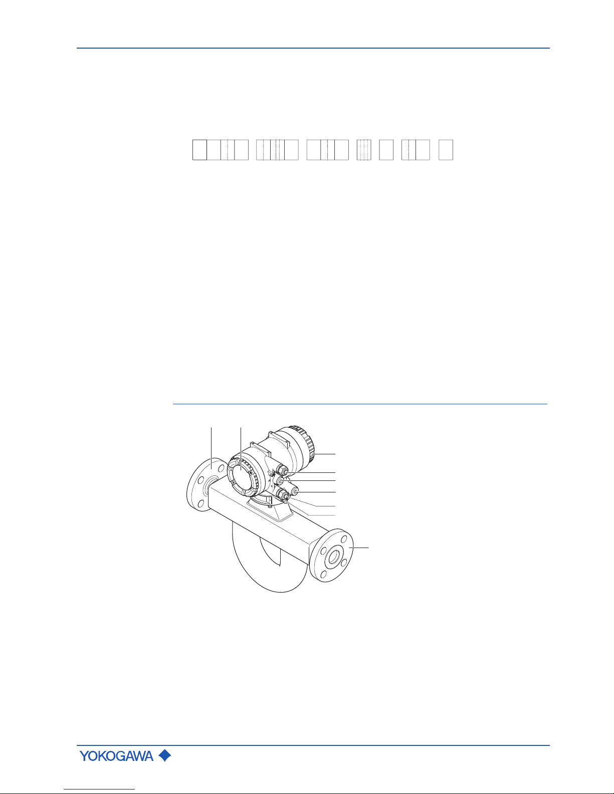
4.4 Flow meter components
Integral type
4
5
2
5
1
5
1
3
6
1 Process connections
2 Back cover for inputs and outputs, and power supply
3 Display cover
4 Power supply cable entry
5 Blind plug
6 Inputs/outputs cable entry
Page 18
General Instruction Manual
Product specification
Mechanical specification
18 / 90
IM 01U10B00-00EN-R, 3rd edition, 2018-07-09
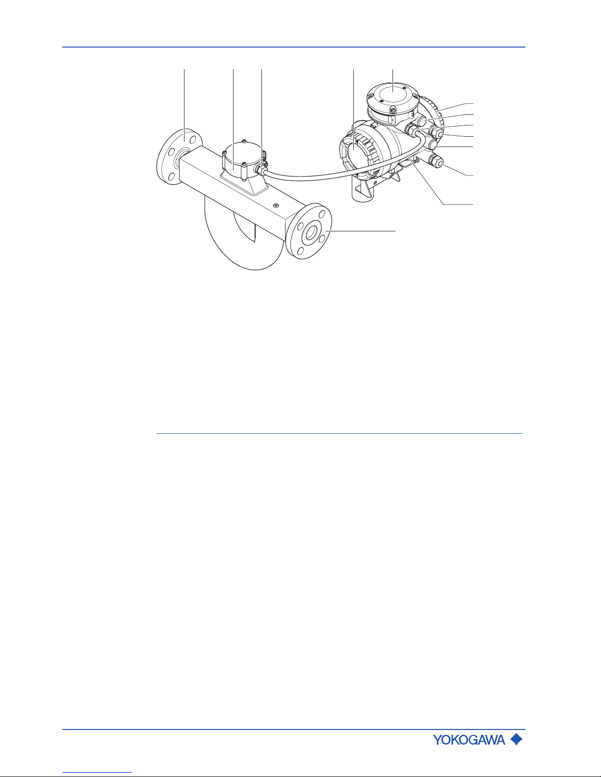
Remote type
4
6
7
7
9
10
3
1
21
3
8
5
1 Process connections
2 Terminal box
3 Cable entry for connecting cable
4 Display cover
5 Sensor connection cover
6 Back cover for inputs and outputs, and power supply
7 Blind plug
8 Inputs/outputs cable entry
9 Power supply cable entry
10 Connecting cable
4.5 Mechanical specification
Mechanical specifications are defined in the related General Specifications (GS):
see GS01U10B0␣␣-00␣␣-R
Page 19
Transport
General Instruction Manual
Transport and storage
IM 01U10B00-00EN-R, 3rd edition, 2018-07-09
19 / 90
5 Transport and storage
5.1 Transport
The following rules apply when transporting the flow meter:
▶ Observe the transport-related instructions on packaging.
▶ In order to avoid damage, do not unpack the flow meter until it is at the installation
site.
▶ Do not remove protective materials, such as protective stickers or covers from
process connections during transport.
▶ Starting at a weight of 15 kg, have at least two persons and/or use suitable tools
(shoulder straps, lifting device, cart) to lift and transport the flow meter.
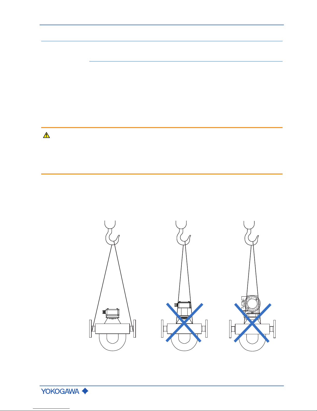
WARNING
Risk of injury from slipping or falling flow meter
▶ Ensure that suspension points of the ropes are located above the flow meter's center
of gravity.
▶ Use a lifting device meeting local regulations.
▶ Attach lifting ropes to process connections.
▶ Do not suspend flow meter from transmitter housing, neck of sensor or flange holes.
The lifting ropes must always be attached to the sensor at the process connections (except for the Rotamass Nano). The depictions that are crossed out in the figure below
show impermissible attachment types. This applies to the remote type, the remote type
with long neck and the integral type, independent of the design. If the process
connections are others than flanges, the holding ropes must be secured against slipping,
if necessary (for example, for the Rotamass Hygienic).
Fig.8: Attachment of the transport ropes to the sensor independent of the design (impermissible attachment types are crossed out)
Page 20

General Instruction Manual
Transport and storage
Storage
20 / 90
IM 01U10B00-00EN-R, 3rd edition, 2018-07-09
5.2 Storage
Please note the following rules apply when storing the flow meter:
NOTICE
Risk of damage to the flow meter due to storage in a damp environment
▶ Protect flow meter from rain and humidity.
▶ Ensure that a relative humidity of 95 % is not exceeded.
NOTICE
Risk of damage to the flow meter due to mechanical wear during storage
▶ Store flow meter in a location that is secured against mechanical influences.
▶ Ensure compliance with the allowed storage temperature, see Specifications [}88].
▶ Protect flow meter against direct insolation to prevent exceeding the allowed storage
temperature.
▶ Protect flow meter from rain and inappropriate humidity.
▶ Keep protective materials such as protective stickers or covers on process
connections or re-apply them.
▶ Prior to storing a used flow meter, completely drain all fluids from the measuring tube,
as well as from the process and heat tracing connections (if applicable), and thoroughly clean the flow meter, see Dismantling and disposal [}86].
Page 21

Installation instructions
General Instruction Manual
Installation
IM 01U10B00-00EN-R, 3rd edition, 2018-07-09
21 / 90
6 Installation
6.1 Installation instructions
WARNING
Risk of injury during installation due to insufficiently trained personnel
▶ Only have skilled personnel install the flow meter.
NOTICE
Risk of damage to the flow meter due to excessive mechanical stress
▶ The flow meter must not be used as a support for climbing (e.g. during installation
work on the tube system). The flow meter must not be used to support external loads
(e.g. as a support for pipes) or as a surface for depositing heavy tools (e.g. during installation work on the pipe system).
▶ The weight of the flow meter may generate additional mechanical forces on the pip-
ing that might lead to tensions at process connections. Design measures must be
taken to prevent the above.
NOTICE
Risk of damage to the flow meter due to mechanical influences
▶ Protect the flow meter from vibration, shocks and mechanical strain.
NOTICE
Meet the environmental conditions of the respective General Specifications
(see GS01U10B0␣␣-00␣␣-R) to prevent disturbance of other sensitive electrical equipment due to increased electromagnetic emissions.
6.1.1 Installation dimensions
Dimensions and installation lengths of sensor and transmitter are listed in the General
Specifications of the corresponding Rotamass Total Insight family in the chapter Mechan-
ical specification.
6.1.2 Installation site
In order to ensure stability while operating the flow meter, the following rules regarding
placement must be followed:
CAUTION
Risk of injury during installation, if space for free movement is insufficient
▶ Select an installation site that offers enough space for installation, electrical installa-
tion, maintenance, etc.
NOTICE
Risk of damage to the flow meter due to extreme environmental conditions
▶ Do not install flow meter in locations subject to severe temperature fluctuations.
▶ Do not install flow meter in locations subject to direct insolation or install additional
sun protection.
▶ Avoid installation sites susceptible to cavitation, such as immediately behind a control
valve.
▶ Install flow meter far removed from motors, transformers or other transmitters.
▶ If the plan calls for installing two sensors of the same kind back-to-back, use a cus-
tomized design. Contact the responsible Yokogawa sales organization.
▶ Operate the flow meter below an elevation of 2000 m above sea level.
▶ If possible, avoid installing the flow meter at the end of a downpipe.
Page 22
General Instruction Manual
Installation
Installation instructions
22 / 90
IM 01U10B00-00EN-R, 3rd edition, 2018-07-09
▶ When installing in a hazardous area, the separate Explosion Proof Type Manual must
be considered.
▶ Install flow meter away from magnetic compasses as it contains no precaution to pre-
vent it from causing compass deviations.
▶ Density indication of the Coriolis flow meter depends on installation orientation and
has to be corrected. For vertical and horizontal orientation (maximum deviation ± 5°)
of the sensor this can be done by the transmitter automatically if the appropriate sensor orientation is selected. For other orientations (inclinations to vertical or horizontal
orientation ≥ 5°) this can not be automatically corrected and has to be taken into account. For highest density accuracy it is recommended to avoid sensor orientations
different to horizontal or vertical installation.
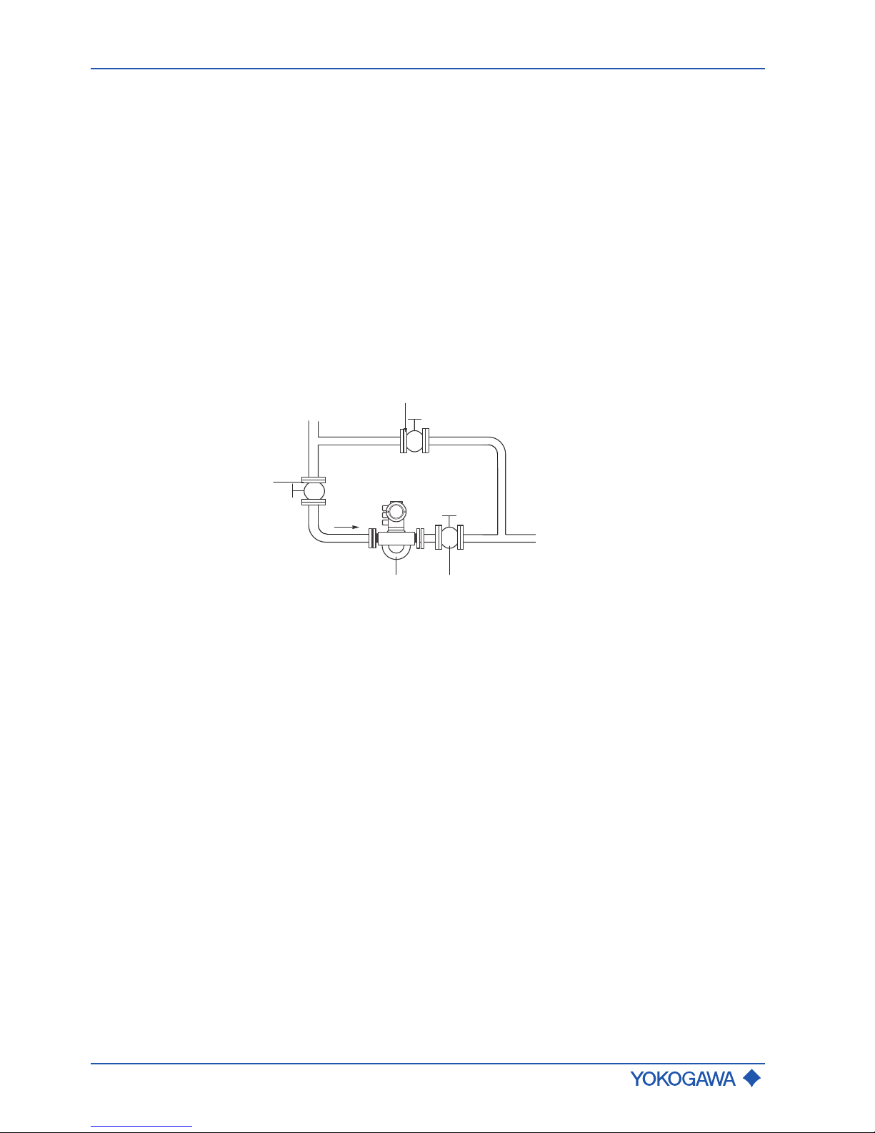
6.1.3 Instructions
Observe the following general installation instructions during installation:
▶ Install the flow meter avoiding shock and vibration as much as possible.
▶ Use closing valves and bypass line to facilitate zero point setting.
1
2
23
Fig.9: Closing valves and bypass line
1 Bypass valve
2 Closing valve
3 Coriolis flow meter
▶ For application involving fluids, avoid installation at highest point of piping. Formation
of gas bubbles and accumulation of gas in measuring tube may result in increased
measurement uncertainties.
▶ In case of gas measurements, avoid installation directly in front of lowest point in pip-
ing. Accumulation of fluids, such as condensate, may result in lower accuracy.
▶ Do not install immediately in front of a free pipe outlet in a downpipe.
▶ Avoid letting the sensor run idle while taking the measurement, e.g. when installed in
front of an air gap to containers in case of filling applications. Doing so may result in
incorrect measurements. To avoid this, install a restriction in the open downpipe or
use an orifice gauge with a diameter smaller than the nominal pipe width.
▶ Each device is tested for pressure prior to delivery.
Page 23
Installation instructions
General Instruction Manual
Installation
IM 01U10B00-00EN-R, 3rd edition, 2018-07-09
23 / 90
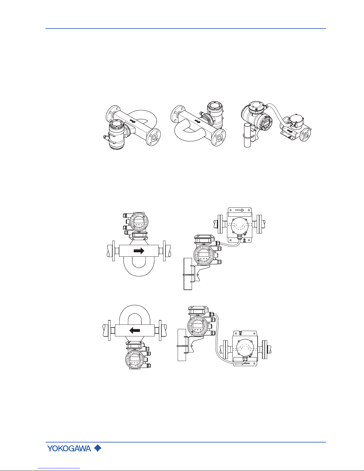
6.1.4 Installation position
Rotamass Total Insight Coriolis mass flow and density meters can be mounted horizontally, vertically and at an incline. The measuring tubes should be completely filled with the
fluid during this process as accumulations of air or formation of gas bubbles in the measuring tube may result in errors in measurement. Straight pipe runs at inlet or outlet are
not required.
Sideways position
The sideways position must be avoided when installing the flow meter, because this may
result in a deterioration of accuracy.
Fig.10: Installation positions to be avoided: Flow meter in sideways position
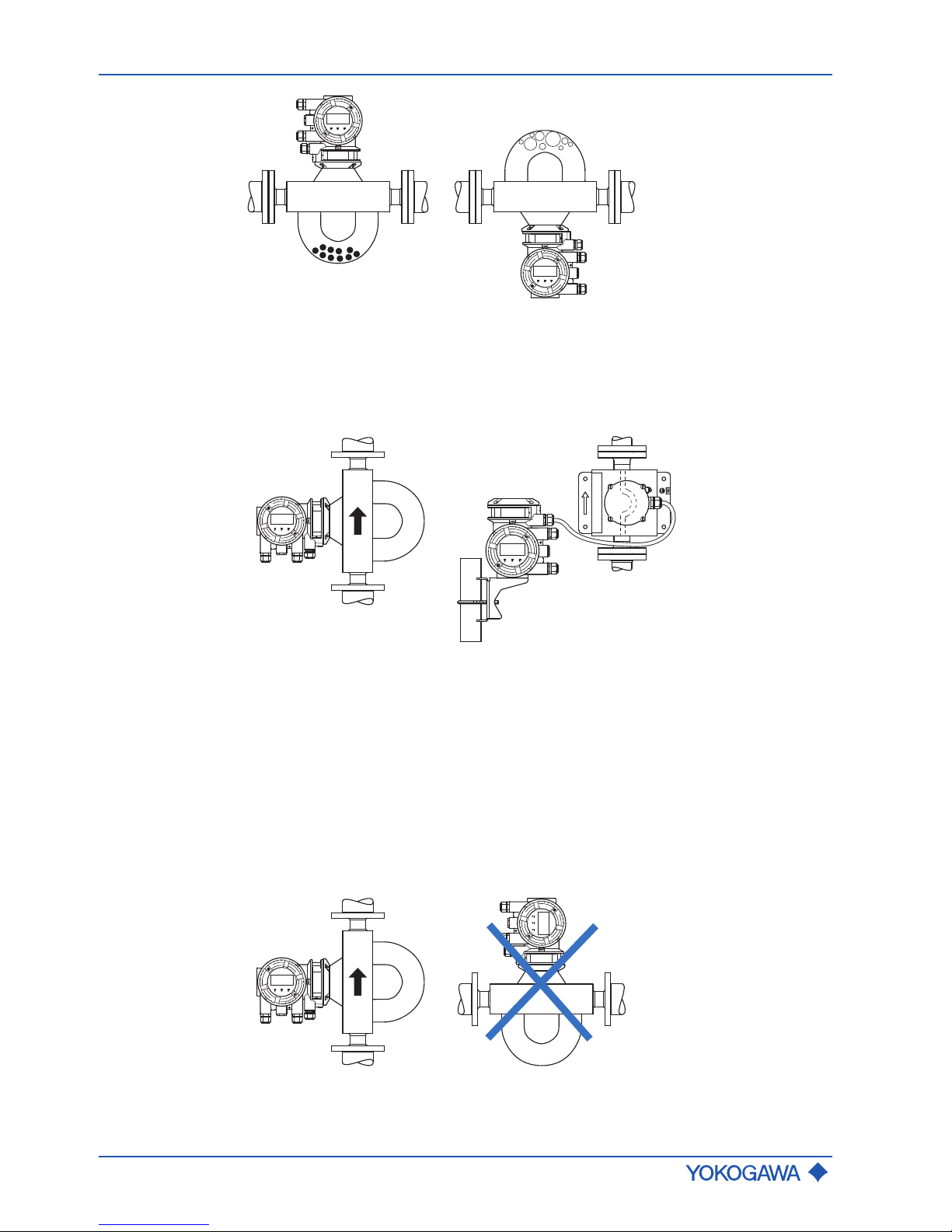
Horizontal
installation
▶ In case of fluids, install the measuring tubes downward so as to avoid gas accumula-
tion in case of a low flow rate.
▶ For gas applications, install the measuring tubes upward so as to avoid fluid accumu-
lation in case of a low flow rate.
Fig.11: Horizontal installation, measuring tubes downward
Fig.12: Horizontal installation, measuring tubes upward
Page 24
General Instruction Manual
Installation
Installation instructions
24 / 90
IM 01U10B00-00EN-R, 3rd edition, 2018-07-09
Fig.13: Risk of solid matter and/or gas accumulation
Vertical installation
(recommended)
▶ Draining the pipe is easier in case of maintenance, production start or product
change.
▶ Allows gas bubbles to escape more easily.
▶ Only one shut-off valve required to ensure zero flow rate when running autozero.
Fig.14: Vertical Installation
6.1.5 Sanitary Installation
EHEDG compliant installation
In order to comply with the requirements of the European Hygienic Engineering and Design Group (EHEDG), the following aspects need to be considered:
▶ The installation must ensure a self-draining of the device (see figure below). A vertical
installation is recommended.
▶ An EHEDG compliant process connection requires a combination of process
connections and gaskets according to the latest version of the EHEDG Position Paper: "Easy cleanable Pipe couplings and Process connections".
Fig.15: EHEDG compliant installation position
Page 25
Installation instructions
General Instruction Manual
Installation
IM 01U10B00-00EN-R, 3rd edition, 2018-07-09
25 / 90
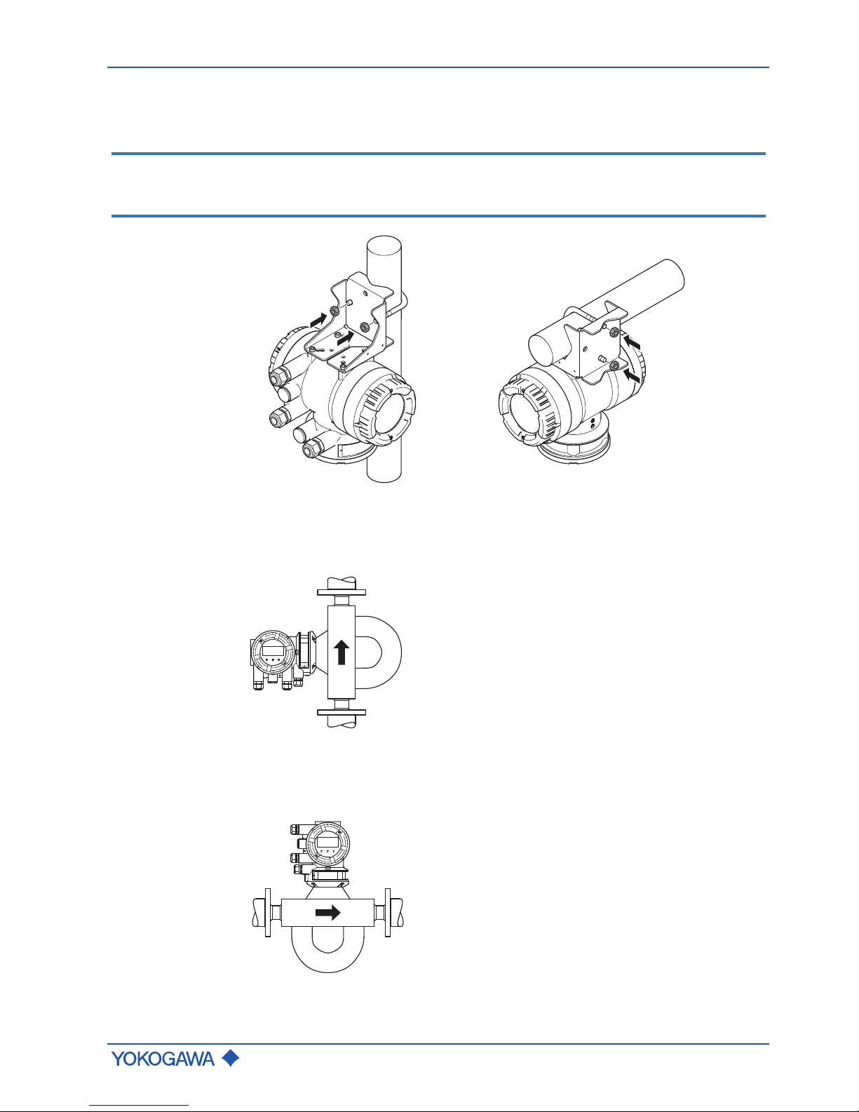
3-A compliant installation
Remote transmitter
installation
▶ For compliance with 3-A sanitary standards, remote transmitter is restricted to hang-
ing installation, as shown in figure below.
NOTICE
Fixation of the transmitter
For fixation of the transmitter at the bracket either hexagon head srews (M6x10) or socket
head screws with rubber cap must be used.
Fig.16: Hanging installation for remote transmitter
Sensor installation
(remote or integral
version)
▶ For compliance with 3-A sanitary standards, a vertical installation of sensor with fluid
flowing upwards (self-draining) is recommended, as shown in figure below.
Fig.17: Vertical (self-draining) installation
▶ A horizontal installation of sensor with tubes down, as shown in figure below, shall be
drained via air purge.
Fig.18: Horizontal installation with tubes down
Page 26

General Instruction Manual
Installation
Installation instructions
26 / 90
IM 01U10B00-00EN-R, 3rd edition, 2018-07-09
▶ For Cleaning-In-Place (CIP) application, the standard minimum flow velocity of
1.5 m/s shall be used for cleaning the sensor. Volumetric flow shall be determined by
using the cross-sectional area at process connection.
Notes on fittings
and gasket
▶ General note: It must be ensured that the inner diameter (ID) of adjacent pipe
matches the ID of process connection of the sensor fitting to ensure 3-A compliance.
▶ For compliance of DIN 11851 process connection (process connection HS2) with 3-A
standards, a special sanitary gasket such as the k-flex gasket system by Kieselmann
GmbH, or similar must be used to retain 3-A compliance.
6.2 Installation instructions
Note the following rules prior to installation:
▶ Check packaging and contents for damage.
▶ Do not remove protective materials such as protective stickers or caps on process
connections until the start of the installation process.
▶ Dispose packaging materials in compliance with country-specific regulations.
Page 27
Sensor installation
General Instruction Manual
Installation
IM 01U10B00-00EN-R, 3rd edition, 2018-07-09
27 / 90
6.3 Sensor installation
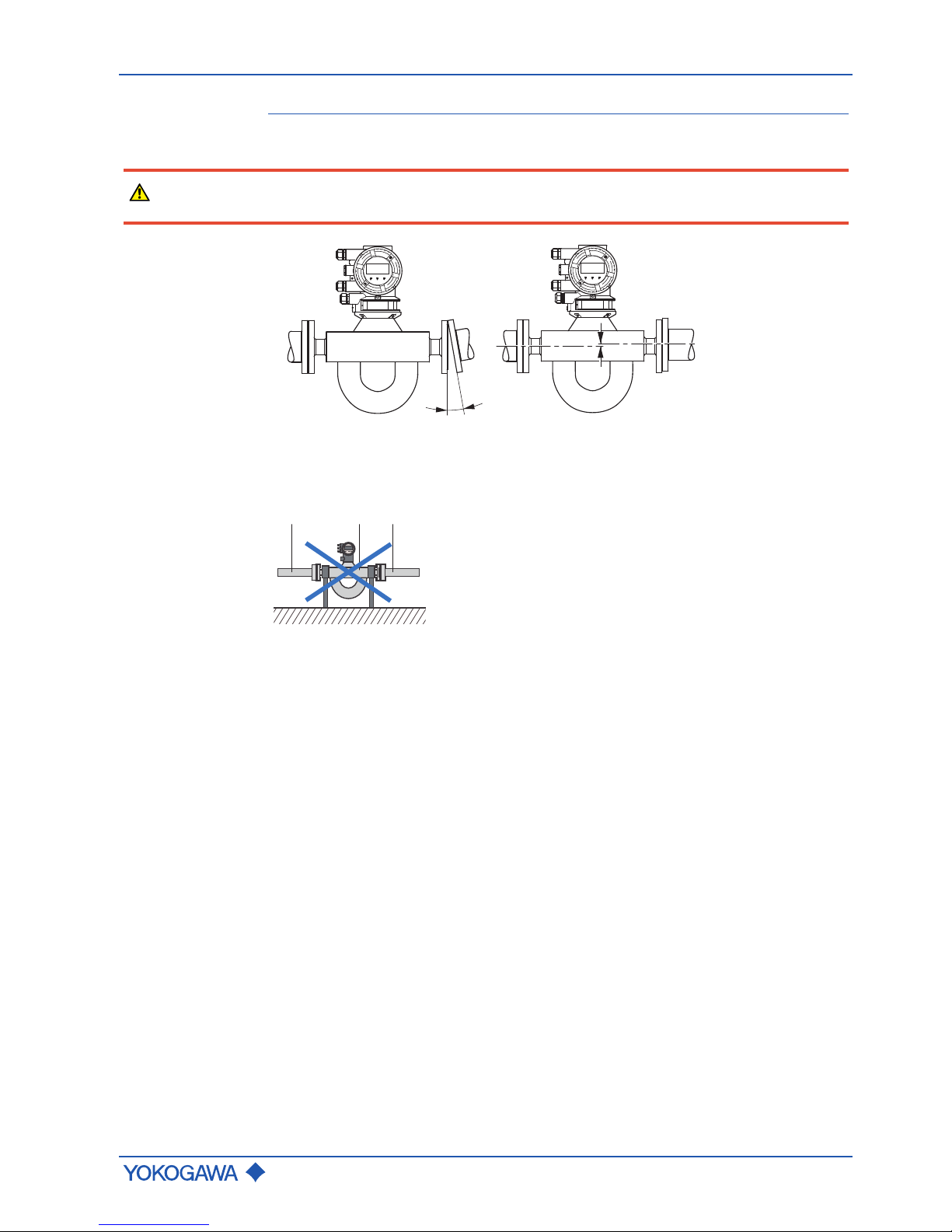
6.3.1 General installation rules
DANGER
Risk of injury due to escaping fluids, if pipe connection is faulty
▶ Correct slope and mismatch of pipe connections before inserting the sensor.
Fig.19: Avoid: Slope and mismatch
▶ Avoid fixing anything directly to the sensor. Doing so may result in increased devia-
tions.
1
1
2
Fig.20: Installation to be avoided: Fixing the sensor
1 Pipe
2 Sensor
▶ Secure pipes before installing the flow meter.
▶ Avoid damaging the process connections.
▶ Flush new pipes before installing the flow meter to remove foreign matter, such as
shavings or other residues.
Avoiding creation of noise
Zero point stability is a prerequisite for exact mass flow measurement. Insufficient installation may lead to mechanical tensions or flow noise which impact zero point stability.
Countermeasures to help avoid noise creation:
▶ Support sensor weight by using soft coupling (silicone or other types of cushioning
materials).
▶ Avoid bending or tensioning the sensor while aligning the pipe.
▶ Avoid reductions or expansions in pipe directly up- or downstream of flow meter.
▶ Avoid placing control valves, apertures or other devices generating noise near the
sensor.
Page 28

General Instruction Manual
Installation
Sensor installation
28 / 90
IM 01U10B00-00EN-R, 3rd edition, 2018-07-09
6.3.2 Installation in pipe
Depending on process connections, the sensor is connected to the pipe by means of
flanges, terminals or thread. The model code provides information on the process
connections selected.
DANGER
Risk of injury due to escaping fluids and damage, if fixing materials are inappropriate or not professionally installed
▶ Fixing materials (screws, nuts, terminals, terminal connectors, gaskets, etc.) are not
included in the delivery and must be provided by the customer. The operator is responsible for selecting suitable gaskets and defining corresponding torque values.
▶ Protective materials such as protective stickers or caps on process connections must
be removed immediately before installation.
▶ The direction in which the fluid flows through the pipe is indicated by an arrow on the
flow meter. The sensor must be installed in accordance with the flow direction indicated to ensure optimal measuring results for density measurements.
Otherwise, the parameter flow direction in the transmitter menu must be changed,
see applicable software instruction manual.
Clamp connection
The clamp connection must be installed as shown in the figure below.
3
2
1
Fig.21: Clamp connection
1 Terminal
2 Gasket
3 Terminal connector
Page 29

Sensor installation
General Instruction Manual
Installation
IM 01U10B00-00EN-R, 3rd edition, 2018-07-09
29 / 90
Fixing the flange
▶ Use screws and nuts suitable for the flanges.
▶ In case the nominal width of the piping deviates from the flow meter, use the appropri-
ate reductions.
▶ Inner gasket diameters should not fall below the inner diameters of the flange.
3
1
2
4
5
Fig.22: Fixing the flange
1 Pipe flange
2 Gasket
3 Sensor flange
4 Bolt
5 Nut
Internal thread
connection
For process connections with an internal thread, the connection must be installed in accordance with the following figure.
1
2
3
Fig.23: Internal thread connection
1 Sensor
2 Gasket (not use in case of NPT)
3 Pipe
Page 30
General Instruction Manual
Installation
Sensor installation
30 / 90
IM 01U10B00-00EN-R, 3rd edition, 2018-07-09
NOTICE
Use of seal tape for installation
In case of process connection with internal thread NPT you have to use a seal tape for installation.
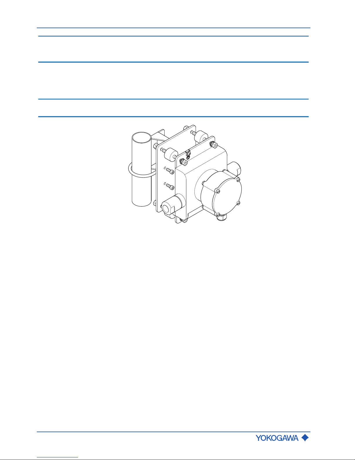
6.3.3 Installation Rotamass Nano (Option PD)
For the Rotamass Nano the sensor can be installed on a DN50 (2") pipe by using a
bracket and U-bolt assy (model code position 15, option PD).
NOTICE
The bracket contains vibration dampers, but for extreme cases of vibration stronger
damping arrangements may be necessary to ensure best performance.
Fig.24: 2" fixing device option /PD for Nano
Page 31

Sensor installation
General Instruction Manual
Installation
IM 01U10B00-00EN-R, 3rd edition, 2018-07-09
31 / 90
6.3.4 Installation recommendation for viscosity measurements
For the Rotamass sensor this function can only be used if it is present an external differential pressure transmitter (to order separately) measuring the pressure difference at the
flow line. The accuracy of the estimated viscosity is strongly depending on the accuracy
of the pressure transmitter and the correct position and implementation of the pressure
taps.
NOTICE
The needed pressure taps have to be placed at the flow line at approximately 4D … 5D
upstream and downstream of the Rotamass sensor. The differential pressure transmitter
is directly connected via analog input to the Rotamass transmitter (analog input function
must be available).
Fig.25: Positioning of pressure taps
① Mounting flanges ④ Differential pressure transmitter
② Pressure taps ⑤ HART communication
③ Rotamass Total Insight
x = approx. 4 to 5 x D
x Flow line upstream or downstream of the Rotamass Total Insight sensor
D Inner diameter of process line
Page 32
General Instruction Manual
Installation
Insulation and heat tracing
32 / 90
IM 01U10B00-00EN-R, 3rd edition, 2018-07-09
6.4 Insulation and heat tracing
6.4.1 Heat tracing
The majority of applications do not require or provide insulation or heat tracing for the
sensor. Product versions with insulation and/or heat tracing are available for specific
technical applications, see applicable General Specifications. Starting with fluid temperatures of approx. 80 °C above or below the ambient temperature, insulating the sensor is
recommended if the goal is to maintain utmost accuracy. These measures are also sensible with increased requirements for fluid temperature stability.
The sensor is heated by means of heat tracing via a heat transfer fluid running through
stainless steel pipes. The heat transfer fluid is supplied through process connections that
can be selected. The operator is responsible for temperature control of the heat carrier.
Here the specifications for pressure and the temperature of the heat transfer fluid must be
met, see applicable General Specifications.
Heat tracing is only available for the remote type of flow meter and must be selected by
including an appropriate device option when placing the order, see applicable General
Specifications.
WARNING
Risk of overheating the transmitter due to increased ambient temperature
Failure of measuring electronics
▶ Observe the maximum allowable ambient temperature for the transmitter.
▶ Install the transmitter at a sufficient distance from heat sources.
6.4.2 Customer-supplied insulation
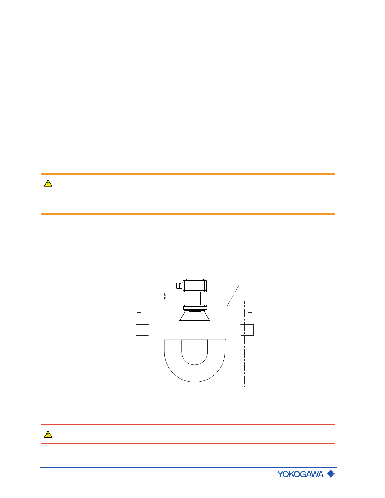
For insulation provided by the customer it is important to select a sensor with the appropriate design type (remote type, sensor with long neck). The space between upper insulation edge and lower edge of the sensor's terminal box must be at least 40 mm.
Recommended insulation thickness is 80 mm and recommended heat transfer coefficient
0.4 W/m² K.
1
min. 40 mm
Fig.26: Customer-supplied insulation
1 Insulation box
DANGER
When installing in hazardous areas, the applicable Explosion Proof Type Manual must be
considered.
Page 33
Transmitter installation
General Instruction Manual
Installation
IM 01U10B00-00EN-R, 3rd edition, 2018-07-09
33 / 90
6.5 Transmitter installation
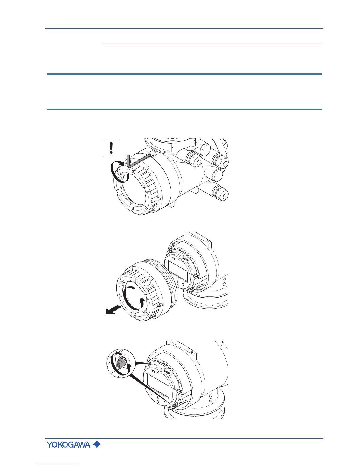
6.5.1 Rotating and replacing the display
The transmitter display can be oriented in line with the flow meter installation position.
NOTICE
The following instruction must only be performed at the following ambient conditions:
▶ at temperatures up to 31°C: relative humidity maximum 80 %
▶ at temperatures between 31°C and 40°C: from 80 % linearly decreasing to 50 % of
maximum relative humidity
1. Switch off power supply.
2. Using an Allen wrench (size: 3.0), turn the locking screw on display screw plug clockwise to remove.
3. Unscrew display cover from transmitter housing.
4. Remove the two screws from the display.
Page 34
General Instruction Manual
Installation
Transmitter installation
34 / 90
IM 01U10B00-00EN-R, 3rd edition, 2018-07-09
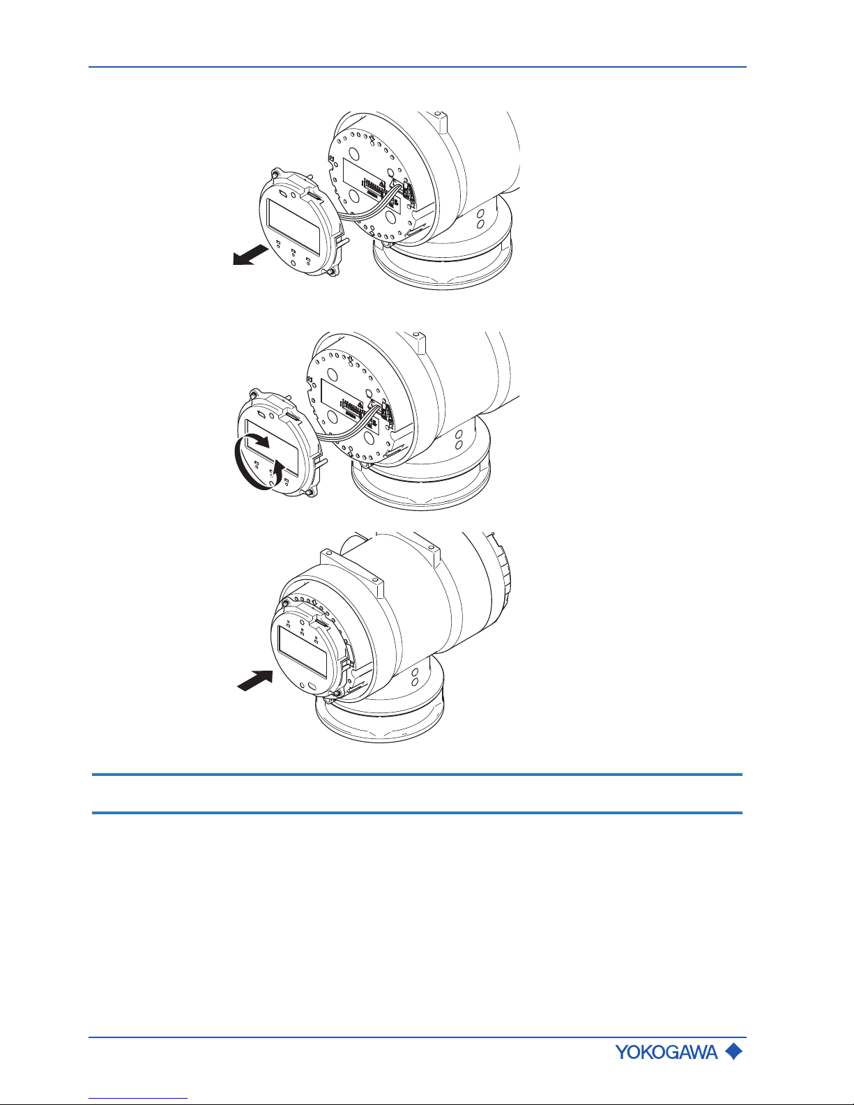
5. Remove the display from housing by pulling forward.
6. Rotate display and push back into housing in the orientation desired.
NOTICE
The display can be removed and replaced by loosening the connector.
Page 35
Transmitter installation
General Instruction Manual
Installation
IM 01U10B00-00EN-R, 3rd edition, 2018-07-09
35 / 90
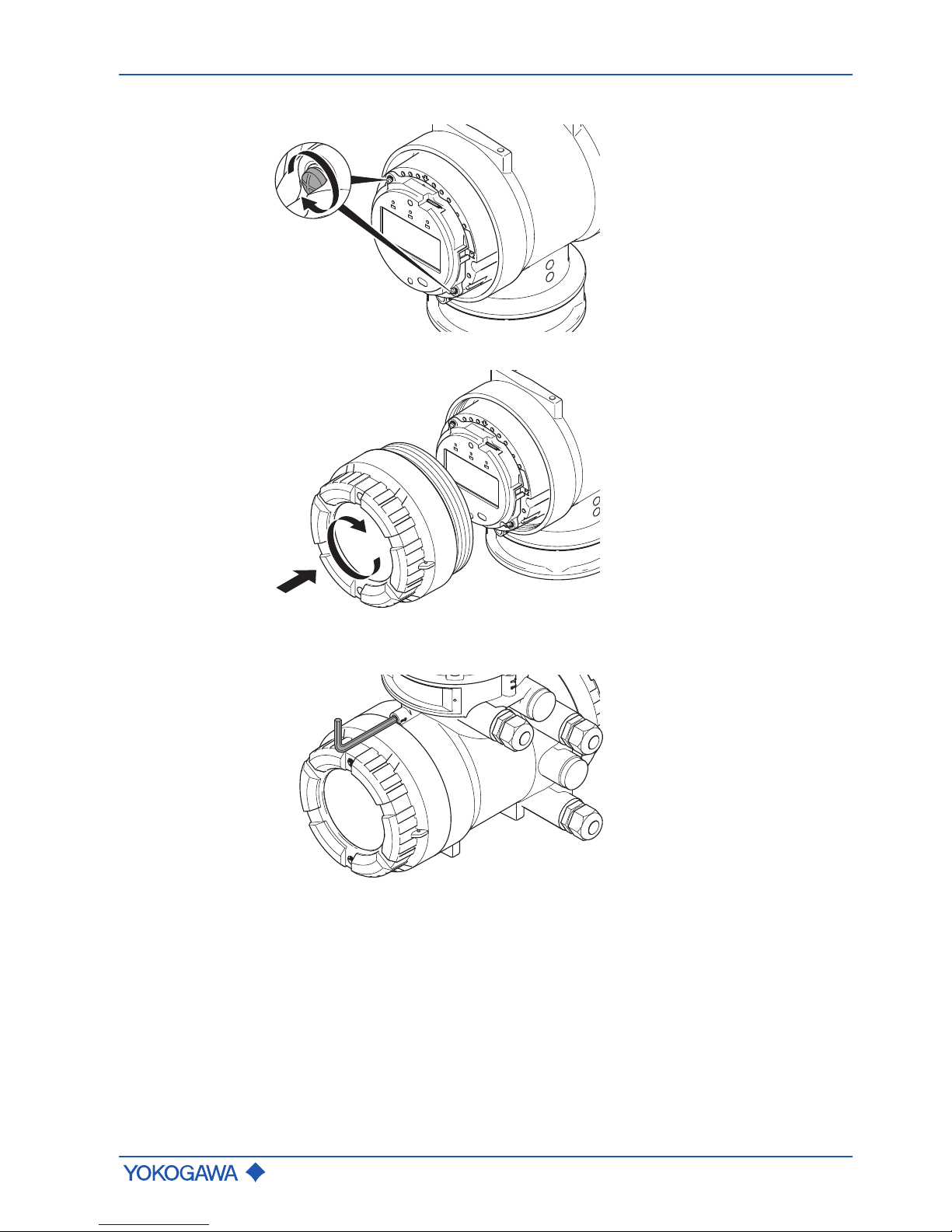
7. Tighten screws.
8. Screw display cover back onto transmitter housing.
9. Using an Allen wrench (size: 3.0), turn the locking screw on display screw plug
counter-clockwise to tighten.
Page 36
General Instruction Manual
Installation
Transmitter installation
36 / 90
IM 01U10B00-00EN-R, 3rd edition, 2018-07-09
6.5.2 Rotating transmitter housing (integral type)
The transmitter housing can be installed in any one of four orientations.
WARNING
Short-circuit hazard caused by penetrating water
Failure of measuring electronics
▶ In order to prevent any water from penetrating the flow meter by way of the cable,
install the transmitter in a way so that the cable gland is not pointed upward.
WARNING
Insufficient sensor grounding connection
Electric shock and ignition in hazardous areas
▶ Use a minimum torque of 4.3 Nm when tightening the screws.
NOTICE
Damage to flow meter
Rotating the transmitter housing several times in the same direction may damage the
connection between sensor and transmitter.
▶ Do not turn transmitter housing more than 270° in the same direction.
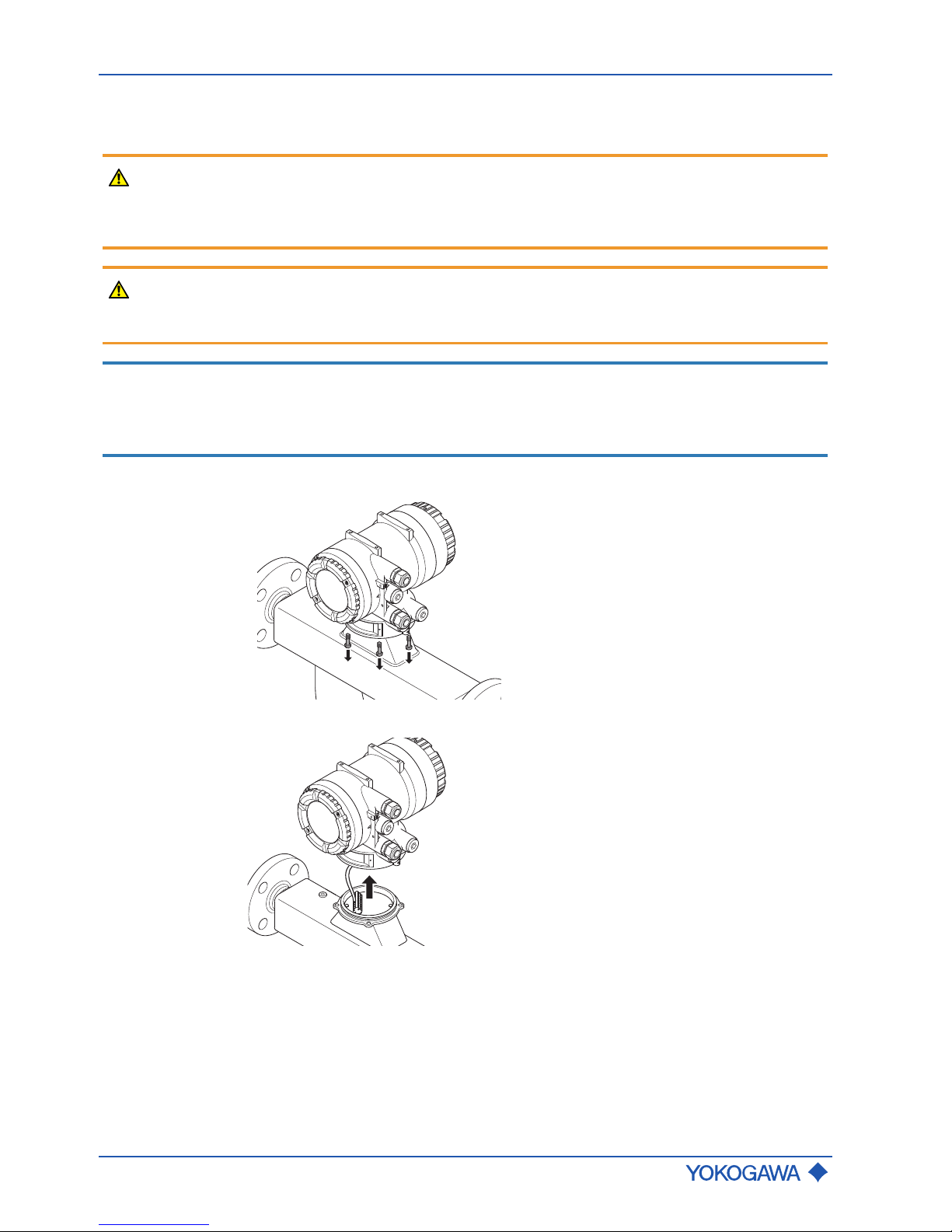
1. By using an Allen wrench (size: 5.0), remove the four fixing screws.
2. Lift transmitter housing.
Page 37
Transmitter installation
General Instruction Manual
Installation
IM 01U10B00-00EN-R, 3rd edition, 2018-07-09
37 / 90
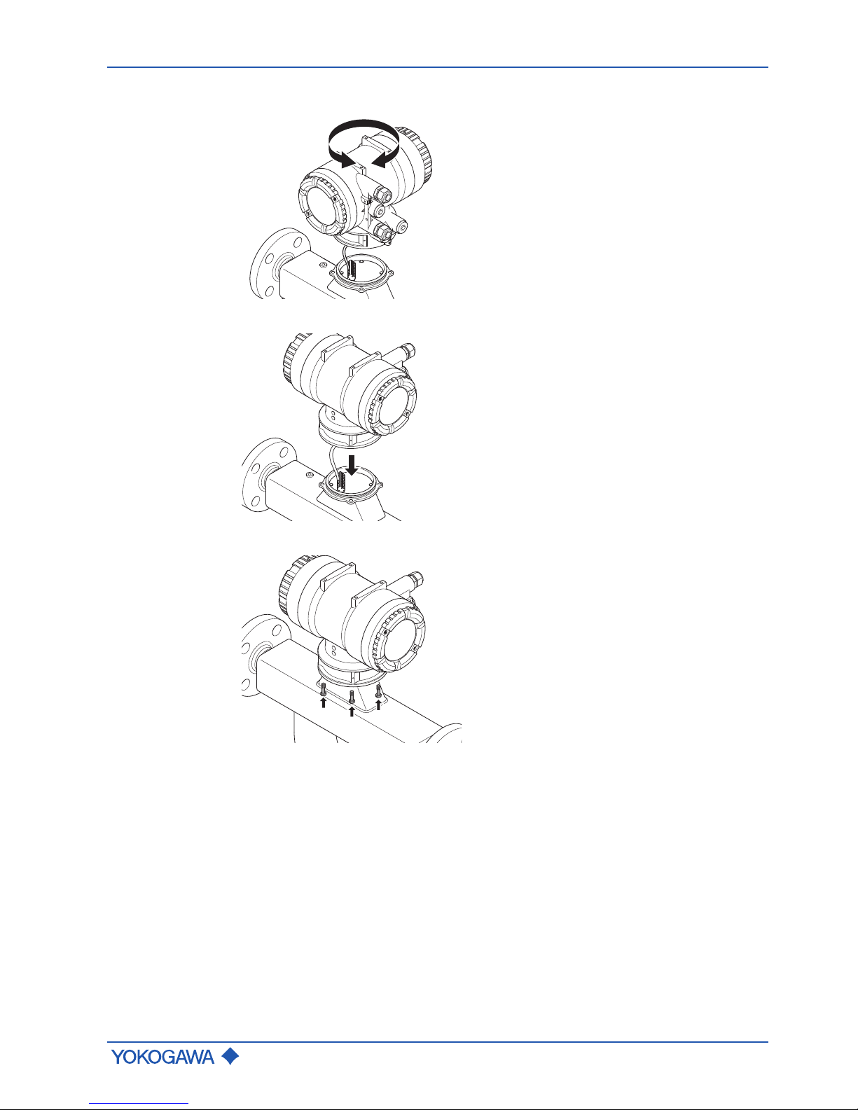
3. Rotate transmitter housing at angles of 90°, 180° or 270°.
4. Place transmitter housing.
5. Tighten the four fixing screws.
Page 38
General Instruction Manual
Installation
Transmitter installation
38 / 90
IM 01U10B00-00EN-R, 3rd edition, 2018-07-09
6.5.3 Rotating the terminal box (remote type)
The terminal box can be installed in any one of four orientations.
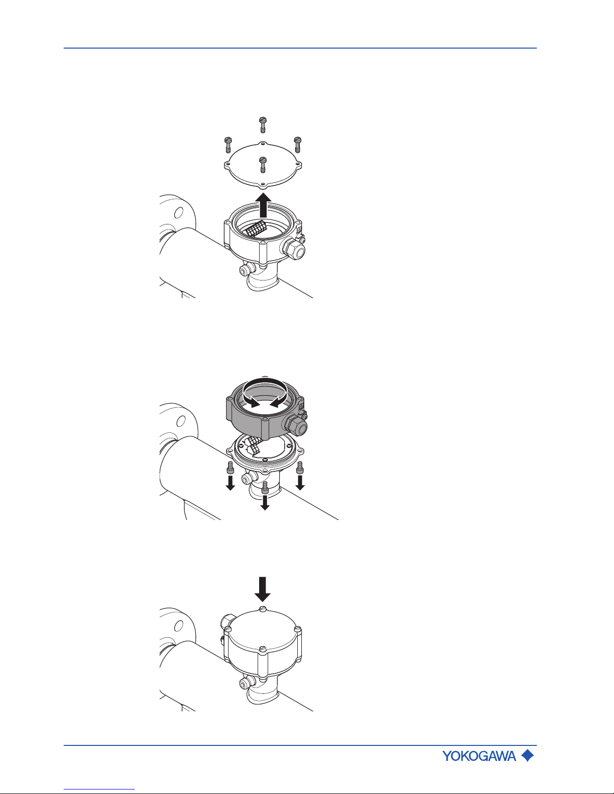
1. Loosen the four fixing screws and remove the cover.
2. Remove the cables so that none of the cables inside can accidentally become
trapped and damaged.
3. By using an Allen wrench (size: 5.0), remove the bottom fixing screws and rotate the
terminal box at an angle of 90°, 180° or 270°.
4. Place the terminal box and tighten the bottom fixing screws using a minimum torque
of 7.4Nm.
5. Attach the cover and tighten the fixing screws using a minimum torque of 7.4Nm.
Page 39

Transmitter installation
General Instruction Manual
Installation
IM 01U10B00-00EN-R, 3rd edition, 2018-07-09
39 / 90
6.5.4 Installing transmitter on pipe (remote type)
WARNING
Risk of overheating the transmitter due to increased ambient temperature
Failure of measuring electronics
▶ Observe the maximum allowable ambient temperature for the transmitter.
▶ Install the transmitter at a sufficient distance from heat sources. Also note the tem-
perature of the fixing pipe.
WARNING
Short-circuit hazard caused by penetrating water
Failure of measuring electronics
▶ In order to prevent any water from penetrating the flow meter by way of the cable,
install the transmitter in a way so that the cable gland is not pointed upward.
CAUTION
Risk of injury and damage to the flow, meter if it is insufficiently attached to
the pipe
▶ Observe the installation notes below.
▶ Tighten screws by using a minimum torque of 7.4 Nm.
NOTICE
Installation at high vibration levels
The mounting bracket for the pipe installation of the transmitter may not be suitable for installation environments with very high levels of vibration. In this case the user is advised
to employ more rugged methods of fixation using the threaded bottom holes directly.
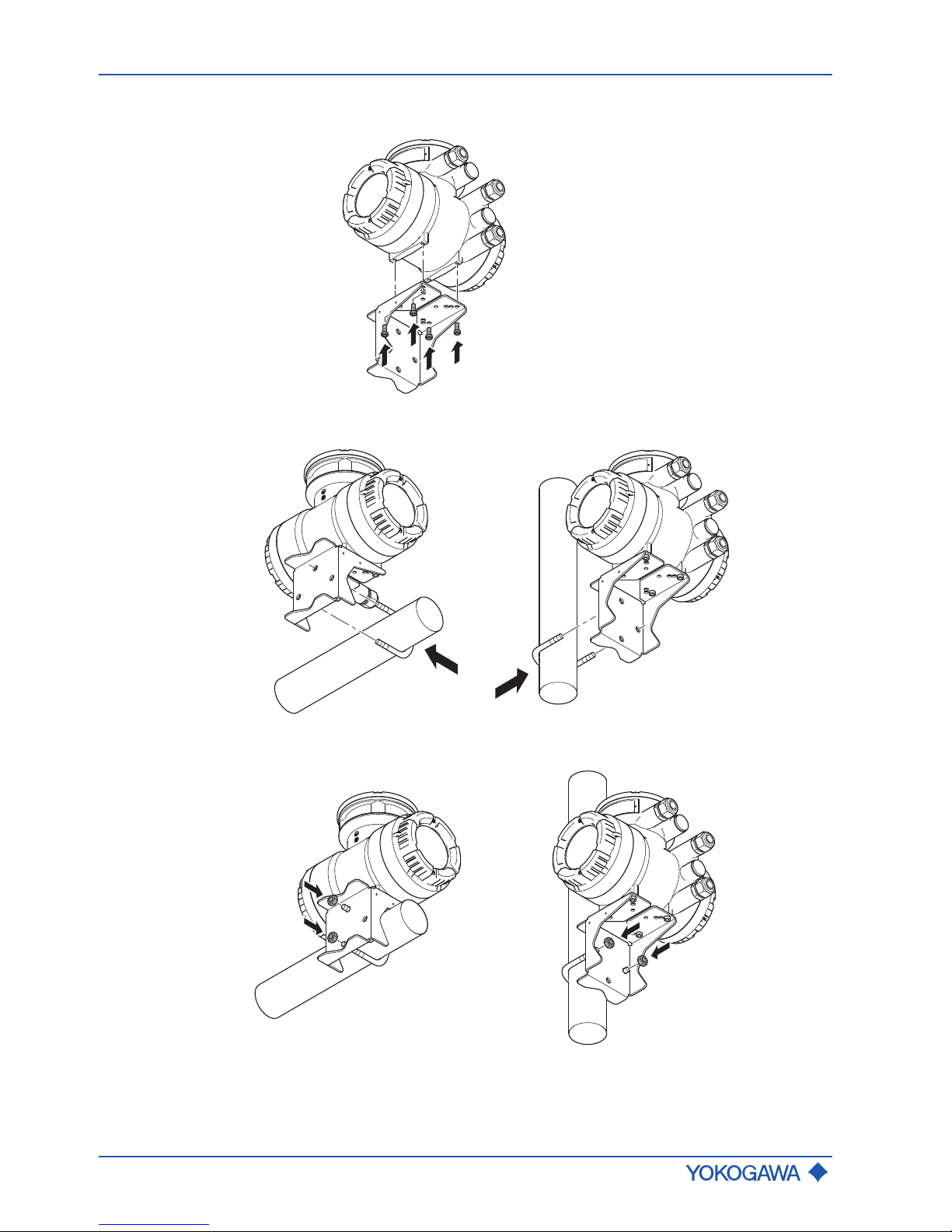
If it is a remote type transmitter, it can be mounted to a pipe size DN50 (2") using the angle bracket and retaining clip included in the delivery.
Page 40
General Instruction Manual
Installation
Transmitter installation
40 / 90
IM 01U10B00-00EN-R, 3rd edition, 2018-07-09
1. Screw angle bracket to bottom of transmitter.
2. Place retaining clip around pipe and slide through drill holes on angle bracket.
3. Fasten retaining clip to bracket using the nuts.
Page 41

Installation check list
General Instruction Manual
Installation
IM 01U10B00-00EN-R, 3rd edition, 2018-07-09
41 / 90
6.6 Installation check list
The following checks must be performed once the flow meter is installed in the pipe:
Check Performed?
State and specification of device
▪ Flow meter checked for external damage?
▪ Does flow meter meet the specifications of the measuring point
(process fluid temperature, process pressure, ambient temperature, measuring range, etc.)?
Installation
▪ Does flow direction on flow meter correspond to the actual flow di-
rection in the pipe?
▪ If not, has the appropriate parameter in the transmitter menu been
switched?
▪ Do measuring point number and nameplate labeling match the in-
stallation site?
▪ Do mounting position and installation match usage (measurement
of gas, liquid) in the process environment and under process conditions?
▪ Is meeting the permissible ambient temperature for the transmitter
ensured?
Process environment and conditions
▪ Is the flow meter protected from environmental influences (precipi-
tation, direct insolation)?
Page 42

General Instruction Manual
Wiring
General wiring rules
42 / 90
IM 01U10B00-00EN-R, 3rd edition, 2018-07-09
7 Wiring
7.1 General wiring rules
Be sure to handle the transmitter cover carefully so that there are no damages and foreign matter adhesion at its thread and O-ring when it is opened or attached.
DANGER
Life-threatening injuries from electric shock
▶ Switch off power supply.
▶ Secure power supply against inadvertent switch-on.
▶ Check that power supply is free of voltage.
DANGER
Life-threatening injuries from ignition of explosive atmospheres
▶ Wait 20 minutes before opening the housing until the capacitors have discharged
and components have cooled off.
▶ Avoid electrostatically charging the device, e.g. by rubbing it with dry cloths.
DANGER
Explosion hazard from electrostatic discharge or brush discharge
Life-threatening injuries or ignition of explosive atmospheres
▶ Avoid actions that could lead to electrostatic discharges. For example, do not wipe
the coated surface of the transmitter using a piece of cloth.
DANGER
When connecting flow meters in hazardous areas, the applicable Explosion Proof Type
Manual must be observed.
WARNING
Risk of injury due to electrical shock
▶ Only have skilled personnel to connect the flow meter.
▶ Do not perform wiring outdoors if it is raining.
WARNING
Risk of injury due to electrical shock, as well as sparking and damage to
the flow meter, if an inappropriate connecting cable is used
▶ It is imperative to adhere to the cable diameter of 0.5 – 2.5 mm for sensor and trans-
mitter connection terminals. When using Litz wire, it must be combined with wire end
ferrules.
▶ The outer cable diameter must meet the specification of the cable glands used.
▶ Install cables tension-free.
WARNING
Risk of sparking and damage to the flow meter due to incorrect wiring
▶ Observe connection diagram for the connecting cable according to chapter Connec-
tion terminals [}46] and Connection terminals [}51].
Page 43

General wiring rules
General Instruction Manual
Wiring
IM 01U10B00-00EN-R, 3rd edition, 2018-07-09
43 / 90
WARNING
Risk of injury due to electrical shock, as well as damage to the flow meter
due to insufficient clamping of the connecting wires
▶ Completely open connection terminal by using the operating tool.
▶ Insert connecting wires with wire end ferrules into the corresponding connection ter-
minal up to the stop.
▶ Close connection terminal.
CAUTION
Don't install the connecting cable at ambient temperatures below -10 °C.
NOTICE
Wiring Work must only be performed at max. 80 % humidity and temperatures up to
31°C, linearly decreasing to 50 % relative humidity at 40°C.
NOTICE
Be aware that conducted and radiated electromagnetic emission may effect the EMC of
adjacent areas.
NOTICE
Be aware that improper earthing, false wiring and use of cable out of specification may
lead to instrument damage and/or disturbance of other sensitive electrical equipment due
to increased electromagnetic emissions/immunity.
NOTICE
Be aware that wrong input voltage may lead to disturbance of other sensitive electrical
equipment due to increased electromagnetic emissions.
▶ The applicable national standards must be considered for installation.
▶ Only sensors and transmitters with compatible model codes may be interconnected. If
these instructions are not observed, flawless function of the flow meter cannot be
guaranteed.
▶ In case of cabling in pipes (Conduit), guide the pipe through the opening in the wiring
and use watertight gaskets to avoid that water runs in. Install the installation pipe at
an angle, as shown in the figure below. Install a drain valve in the bottom end of the
vertical pipe and regularly open that valve.
Drain valve
▶ Unused cable entries must be closed using blind plugs.
▶ Install cables hanging down to prevent water from flowing along the cable into the
flow meter.
▶ The electrical connection between potential equalization system and grounding
connection must be safe, see Grounding connections and sensor circuits [}44].
▶ Ensure that housing gaskets are positioned in the lining grooves and not damaged.
Page 44

General Instruction Manual
Wiring
Grounding connections and sensor circuits
44 / 90
IM 01U10B00-00EN-R, 3rd edition, 2018-07-09
7.2 Grounding connections and sensor circuits
WARNING
Risk of injury from electrical shock due to inadequate grounding
▶ Perform potential equalization at the grounding terminals provided for this purpose
according to the figure “Grounding connections on transmitter and sensor”.
3
2
1
Fig.27: Grounding connections on transmitter and sensor
1 Grounding screw in transmitter terminal box for grounding conductor
2 Grounding terminal on transmitter for potential equalization
3 Grounding terminal on sensor for potential equalization
D +
D -
S1 +
S1 -
S2 +
S2 -
TP1
TP2
TP3
D +
D -
S1 +
S1 -
S2 +
S2 -
TP1
TP2
TP3
COM
3 2 1
1 2 3 4 5 6
Fig.28: Connection terminal circuits (transmitter on the left side, sensor on the right side)
1 Driver circuit (D+/D-) 4 Signal grounding
2 Sensor circuits (S1+/S1-, S2+/S2-) 5 Transmitter
3 Temperature measurement circuit
(TP1, TP2, TP3)
6 Sensor
Page 45

Connecting cable installation
General Instruction Manual
Wiring
IM 01U10B00-00EN-R, 3rd edition, 2018-07-09
45 / 90
7.3 Connecting cable installation
With remote type flow meters, sensors and transmitters are connected by means of connecting cables.
CAUTION
Risk of damage to the flow meter due to incorrect sealing
In case of metric cable entry ensure appropriate IP rating and suitability of O-ring of used
accessory (e.g. cable glands).
In case of NPT cable entry ensure appropriate sealing measures (e.g. use of sealing
tape).
In order to obtain optimum measuring results and ensure compliance with the specification, it is imperative that an original connecting cable and original glands from Rota Yokogawa are used. In order to ensure the IP code, the cable must be professionally installed
at the entries. If necessary, the cable may be shortened using the enclosed termination
kit. Refer to the cable termination instructions enclose to each termination kit that is attached to each cable.
1 2 3
4
7 8
65
Fig.29: Cable gland parts mounting
1 Cap nut 5 Outer cable shield
2 Connecting cable 6 Outer cone part
3 Plastic part 7 Mounting thread
4 Inner cone part 8 Housing cable entry
If the connecting cable, included in the delivery, is too short, additional lengths can be
procured through the Yokogawa sales organization.
Page 46

General Instruction Manual
Wiring
Connecting cable installation
46 / 90
IM 01U10B00-00EN-R, 3rd edition, 2018-07-09
7.3.1 Connection terminals
The delivery includes an operating tool for connecting the connecting cable to the
connection terminals.
D +
D -
S1 +
S1 -
S2 +
S2 -
TP1
TP2
TP3
D +
D -
S1 +
S1 -
S2 +
S2 -
TP1
TP2
TP3
COM
3 2 1
1 2 3 4 5 6
Fig.30: Connection terminal circuits (transmitter on the left side, sensor on the right side)
1 Driver circuit (D+/D-) 4 Signal grounding
2 Sensor circuits (S1+/S1-, S2+/S2-) 5 Transmitter
3 Temperature measurement circuit
(TP1, TP2, TP3)
6 Sensor
Installation of
standard connecting
cable option L
␣␣␣
Fig.31: Transmitter and sensor interconnection diagram
1 Sensor
2 Transmitter
3 Potential equalization system
Page 47

Connecting cable installation
General Instruction Manual
Wiring
IM 01U10B00-00EN-R, 3rd edition, 2018-07-09
47 / 90
green
red
blue
white
brown
yellow
drain
wire
Fig.32: Terminated standard connecting cable L␣␣␣, transmitter side
Connection scheme of standard connecting cable option L␣␣␣
Standard connecting cable option L
␣␣␣
Signal Coaxial wire
Coaxial wire pair colour Wire type Wire colour
D+
green
Core wire transparent
D- Shield black
S1+
red
Core wire transparent
S1- Shield black
S2+
blue
Core wire transparent
S2- Shield black
Standard connecting cable option L
␣␣␣
Signal Single wire
Wire type Wire colour
TP1
Conductor
white
brownTP2
TP3 yellow
COM
1)
Drain wire
1)
–
1)
Present only at transmitter side
Page 48

General Instruction Manual
Wiring
Connecting cable installation
48 / 90
IM 01U10B00-00EN-R, 3rd edition, 2018-07-09
Installation of fire
retardant connecting
cable option Y
␣␣␣
1 2
3
D+
D–
S1+
S1–
S2+
S2–
TP1
TP2
TP3
D+
D–
S1+
S1–
S2+
S2–
TP1
TP2
TP3
COM
Fig.33: Transmitter and sensor interconnection diagram
1 Sensor
2 Transmitter
3 Potential equalization system
2
4
5
3
Shield wire
1
Fig.34: Terminated fire retardant connecting cable Y␣␣␣, transmitter side
Connection scheme of fire retardant connecting cable option Y␣␣␣
Y
␣␣␣
-cable
Signal Conductor pair number
1)
Conductor colour
D+
1
white
D- blue
S1+
2
white
S1- blue
S2+
3
white
S2- blue
TP1
4
white
TP2 blue
TP3 5 white
COM
2)
Shield wire
2)
–
1)
Conductor pair number refers to the numbers printed on the single conductors
2)
Present only at transmitter side
Page 49
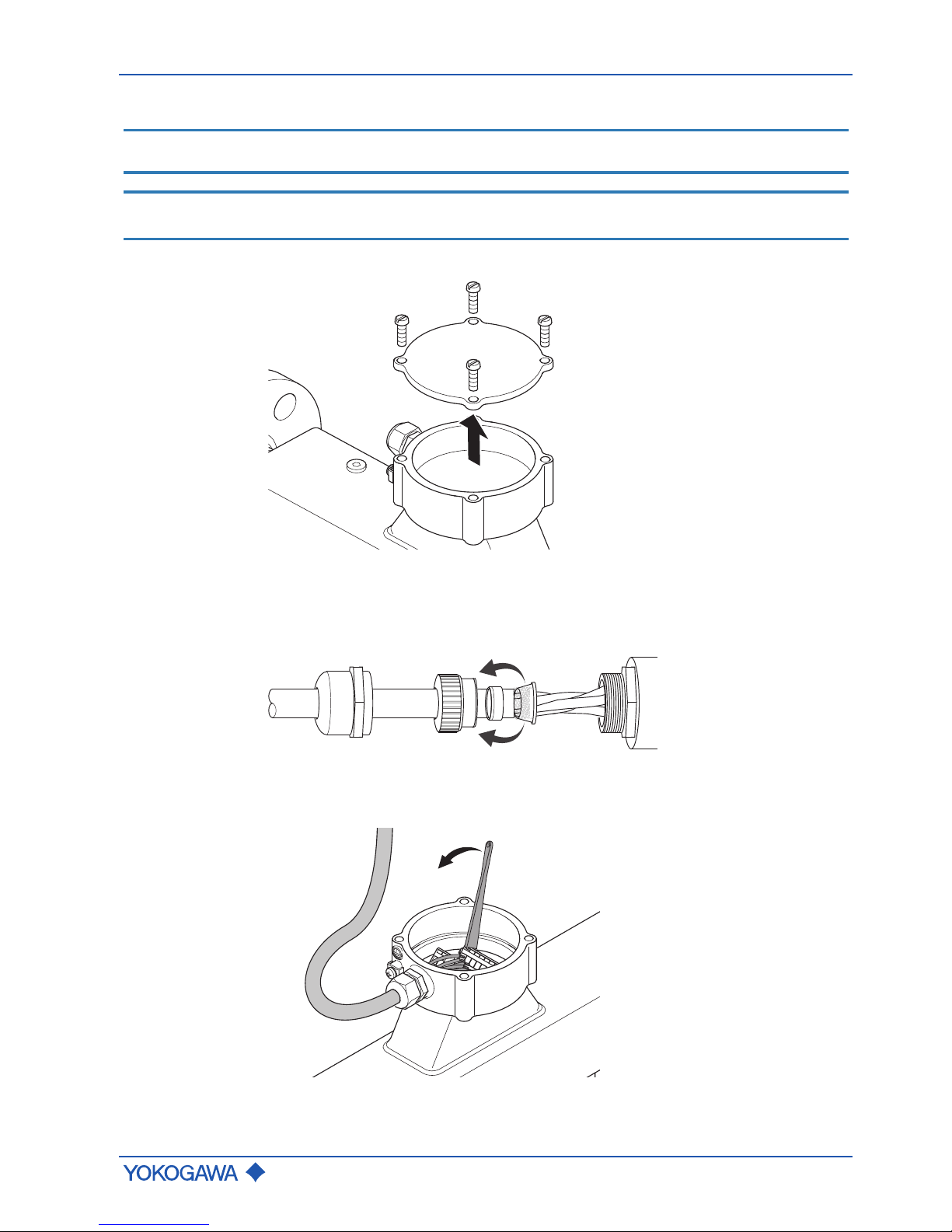
Connecting cable installation
General Instruction Manual
Wiring
IM 01U10B00-00EN-R, 3rd edition, 2018-07-09
49 / 90
7.3.2 Connecting the connecting cable to sensor
NOTICE
Use the cable end without shield wire to connect to the sensor (observe labeling).
NOTICE
If the cable is not terminated or was shortened, observe the separate instructions in the
included terminating set.
1. Loosen the four screws from the neck cover and remove cover.
2. Remove connector nut from cable gland and pull out clamped insert.
3. Push cable through connector nut and clamped insert.
4. Remove precut outer casing of cable.
5. Pull back outer shield of cable over clamped insert.
6. Feed cable through cable entry into sensor.
7. Use the operating tool to connect wires to connection terminals in accordance with
terminal diagram Connection terminals [}46].
8. Assemble the cable gland and tighten connector nut.
9. Place cover onto sensor and fasten with four screws.
Page 50
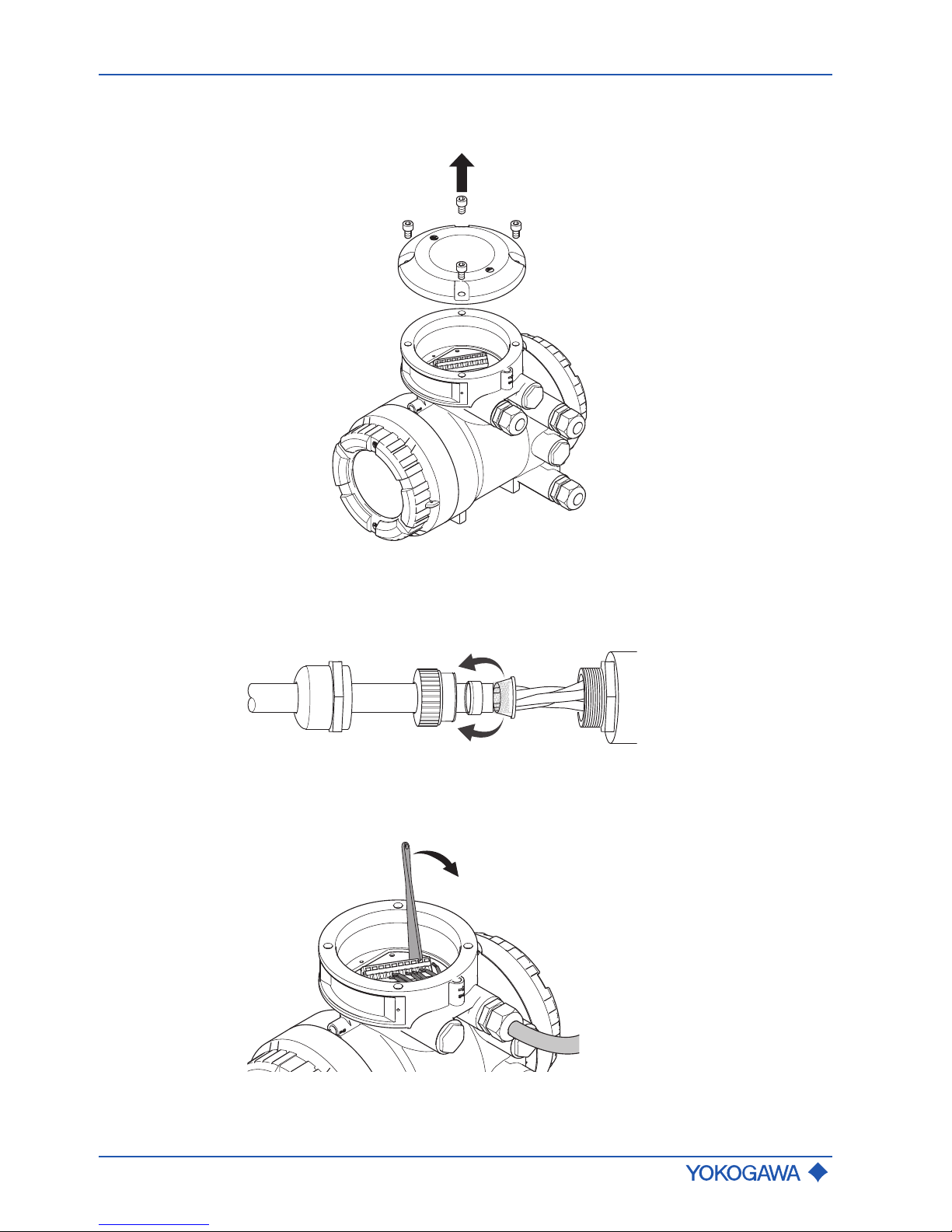
General Instruction Manual
Wiring
Connecting cable installation
50 / 90
IM 01U10B00-00EN-R, 3rd edition, 2018-07-09
7.3.3 Connecting the connecting cable to transmitter
1. Loosen the four screws from the sensor connection cover and remove cover.
2. Remove connector nut from cable gland and pull out clamped insert.
3. Push cable through connector nut and clamped insert.
4. Remove precut outer casing of cable.
5. Pull back outer shield of cable over clamped insert.
6. Feed cable through cable entry into transmitter.
7. Use the operating tool to connect wires to connection terminals in accordance with
terminal diagram (Connection terminals of connecting cable).
8. Assemble the cable gland and tighten connector nut.
9. Place sensor connection cover onto transmitter and fasten with four screws.
Page 51
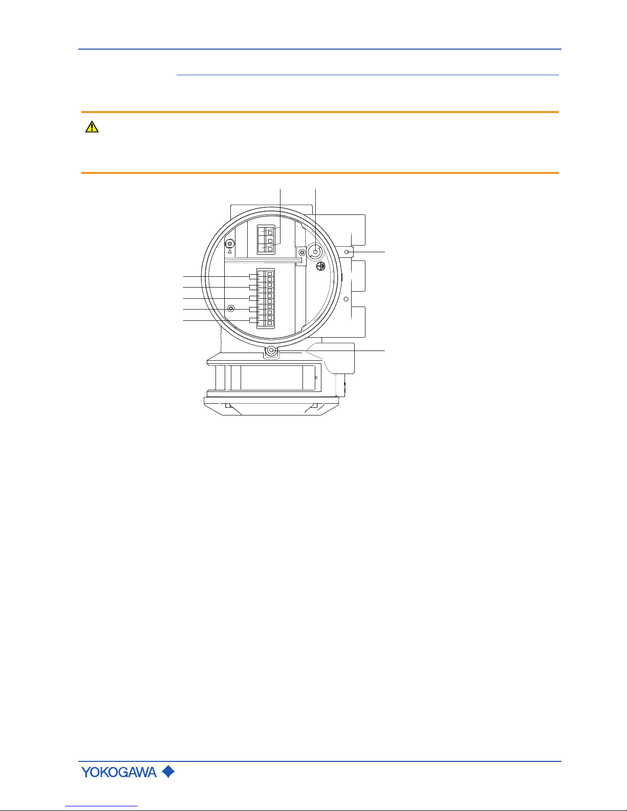
Transmitter
General Instruction Manual
Wiring
IM 01U10B00-00EN-R, 3rd edition, 2018-07-09
51 / 90
7.4 Transmitter
7.4.1 Connection terminals
WARNING
Risk of injury from electrical shock due to inadequate grounding
▶ Use grounding screw to connect the grounding conductor.
▶ Use an M4 ring-type or forked cable lug for the grounding conductor of the connect-
ing cable.
L/+ N/-
3
1
4
2
8
7
6
5
9
Fig.35: Terminal box for I/O outputs and transmitter power supply
1 Power supply connection terminals 6 Connection terminals for I/O2 +/2 Grounding screw for connecting
grounding conductor
7 Connection terminals for I/O3 +/-
3 Grounding terminal for potential
equalization
8 Connection terminals for I/O4 +/-
4 Locking screw 9 WP: Write-protection terminal
5 Connection terminals for I/O1 +/-
Page 52
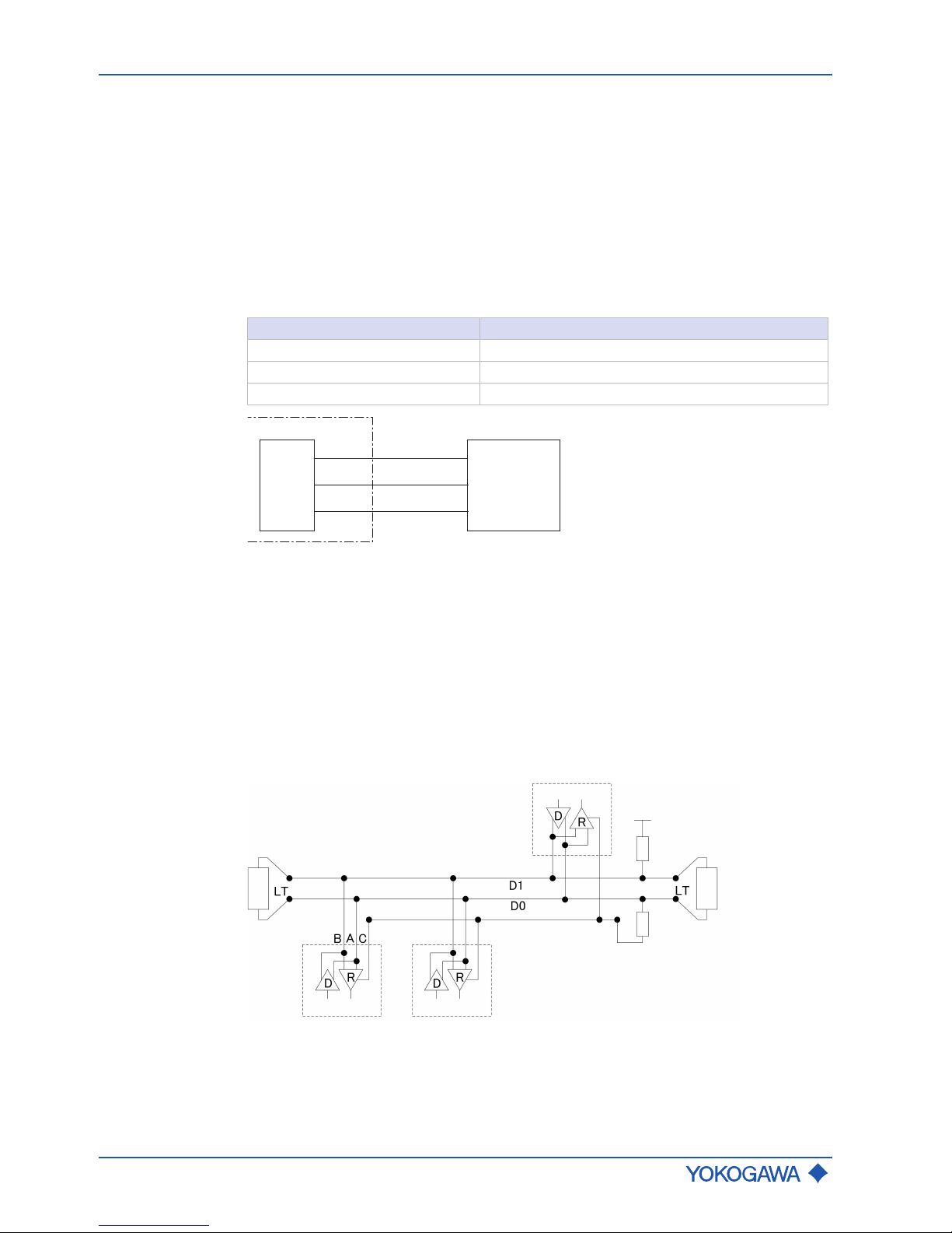
General Instruction Manual
Wiring
Transmitter
52 / 90
IM 01U10B00-00EN-R, 3rd edition, 2018-07-09
7.4.2 HART communication
For devices with HART communication, the HART interface, along with the analog signal,
is available at the output Iout1. A load resistance of 230 – 600Ω at Iout1 is recommended.
How to connect to the communication tools is described in the applicable Software Instruction Manual.
7.4.3 MODBUS communication
Modbus
interface
Modbus interface of Rotamass Total Insight is implemented in accordance with "MODBUS over serial line specification and implementation guide V1.02", for details of instrumentation see website of the Modbus organization (http://www.modbus.org/).
Modbus
connections
Terminal Description
I/O3 - Modbus C (Common)
I/O4 + Modbus B (D1)
I/O4 - Modbus A (D0)
MODBUS_B
MODBUS_A
MODBUS_C
IO4+
IO4-
IO3-
RD+
RD-
GND
RS485
ROTAMASS
Modem
Fig.36: MODBUS communication
Modbus cable
3-Wire cable (twisted pair (D0, D1) and Common) with shield should be used. Wire gauge
should be AWG24 or wider.
Rotamass Total Insight has a RS485 electrical interface, operating in slave mode and
communicating with the following default specification:
Default Modbus
setting
▪ Modbus baud rate: 19200 bps
▪ Modbus transfer mode: RTU
▪ Modbus parity: Even
▪ Modbus stop bit: 1 stop bit
For further details, see applicable software instruction manual (SWIM).
Balanced Pair
Master
Pull Up
Pull Down
LT: Line Termination
Common
Slave n
ROTAMASS
Fig.37: Modbus connection
Page 53

Transmitter
General Instruction Manual
Wiring
IM 01U10B00-00EN-R, 3rd edition, 2018-07-09
53 / 90
7.4.4 Assignment of inputs and outputs
The table below shows possible connection terminal assignments for I/O outputs depending on model code Position 13.
The following figure shows the relevant position of the model code:
- - - - /-
RC
1 2 3 4 6 75 9 10 11 12 13 14 158
Configuration of input/output terminals for HART communication
HART I/O
Model code
Position 13
Connection terminal assignment
I/O1 +/- I/O2 +/- I/O3 +/- I/O4 +/- WP
JA
Iout1
Active
P/Sout1
Passive
– – Write-protect
JB
Iout1
Active
P/Sout1
Passive
P/Sout2
Passive
Iout2
Active
Write-protect
JC
Iout1
Active
P/Sout1
Passive
Sin
Iout2
Active
Write-protect
JD
Iout1
Active
P/Sout1
Passive
Sout
Passive
P/Sout2
Passive
Write-protect
JE
Iout1
Active
P/Sout1
Passive
Sin
P/Sout2
Passive
Write-protect
JF
Iout1
Active
P/Sout1
Passive
Sin
P/Sout2
Active
Internal pullup resistor
Write-protect
JG
Iout1
Active
P/Sout1
Passive
Sin
P/Sout2
Active
Write-protect
JH
Iout1
Active
P/Sout1
Passive
Iout2
Passive
Iin
Active
Write-protect
JJ
Iout1
Active
P/Sout1
Passive
P/Sout2
Passive
Iin
Active
Write-protect
JK
Iout1
Active
P/Sout1
Passive
Sin
Iin
Active
Write-protect
JL
Iout1
Active
P/Sout1
Passive
Iout2
Passive
Iin
Passive
Write-protect
JM
Iout1
Active
P/Sout1
Passive
P/Sout2
Passive
Iin
Passive
Write-protect
JN
Iout1
Active
P/Sout1
Passive
Sin
Iin
Passive
Write-protect
JP
Iout1
Passive
P/Sout1
Passive
Iout2
Passive
– Write-protect
JQ
Iout1
Passive
P/Sout1
Passive
Iout2
Passive
P/Sout2
Passive
Write-protect
JR
Iout1
Passive
P/Sout1
Passive
NAMUR
Iout2
Passive
– Write-protect
Page 54

General Instruction Manual
Wiring
Transmitter
54 / 90
IM 01U10B00-00EN-R, 3rd edition, 2018-07-09
Model code
Position 13
Connection terminal assignment
I/O1 +/- I/O2 +/- I/O3 +/- I/O4 +/- WP
JS
Iout1
Passive
P/Sout1
Passive
NAMUR
Iout2
Passive
P/Sout2
Passive
NAMUR
Write-protect
Iout1 Analog current output with HART communication
Iout2 Analog current output
Iin Analog current input
P/Sout1 Pulse or status output
P/Sout2 Pulse or status output
Sin Status input
Sout Status output
Configuration of input/output terminals for Modbus communication
Modbus I/O
Model
code
position
13
Connection terminal assignment
I/O1 +/- I/O2 +/- I/O3 + I/O3 - I/O4 + I/O4 - WP
M0 –
P/Sout1
Passive
– Modbus C Modbus B Modbus A
Writeprotect
M2
Iin
Active
P/Sout1
Passive
– Modbus C Modbus B Modbus A
Writeprotect
M3
P/Sout2
Passive
P/Sout1
Passive
– Modbus C Modbus B Modbus A
Writeprotect
M4
P/Sout2
Active
P/Sout1
Passive
– Modbus C Modbus B Modbus A
Writeprotect
M5
P/Sout2
Active
Internal
pull-up
resistor
P/Sout1
Passive
– Modbus C Modbus B Modbus A
Writeprotect
M6
Iout1
Active
P/Sout1
Passive
– Modbus C Modbus B Modbus A
Writeprotect
M7
Iin
Passive
P/Sout1
Passive
– Modbus C Modbus B Modbus A
Writeprotect
Iout Analog current output, no HART
Iin Analog current input
P/Sout1 Pulse or status output
P/Sout2 Pulse or status output
Page 55

Transmitter
General Instruction Manual
Wiring
IM 01U10B00-00EN-R, 3rd edition, 2018-07-09
55 / 90
7.4.5 Output signals
Galvanic isolation
All circuits for inputs, outputs and power supply are galvanically isolated from each other.
Active current
output lout
One or two current outputs are available depending on model code position 13.
Depending on the measured value, the active current output delivers 4 – 20 mA.
It may be used for output of the following measured values:
▪ Flow rate (mass, volume, net partial component flow of a mixture)
▪ Density
▪ Temperature
▪ Pressure
▪ Concentration
For HART communication devices, it is supplied on the current output lout1. The current
output may be operated in compliance with the NAMUR NE43 standard.
Value
Nominal output current 4 – 20 mA
Maximum output current range 2.4 – 21.6 mA
Load resistance ≤ 750Ω
Load resistance for secure HART communication 230–600 Ω
Additive maximum deviation 8 µA
Additive output deviation for deviation from 20 °C ambient
temperature
0.8 µA/ °C
Iout+
Iout-
ROTAMASS
1
Fig.38: Active current output connection lout HART
① Receiver
Page 56
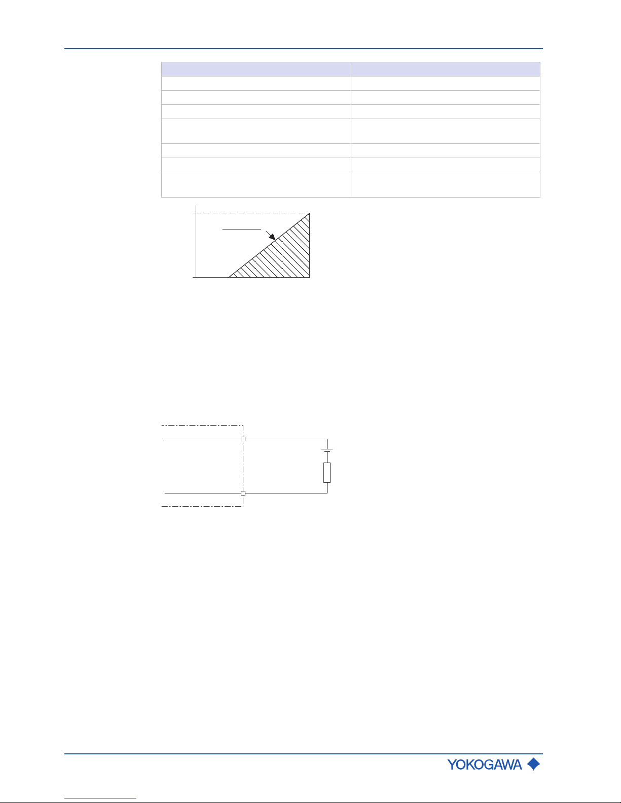
General Instruction Manual
Wiring
Transmitter
56 / 90
IM 01U10B00-00EN-R, 3rd edition, 2018-07-09
Passive current
output lout
Value
Nominal output current 4 – 20 mA
Maximum output current range 2.4 – 21.6 mA
External power supply 10.5–32 V
DC
Load resistance for secure HART communication
230–600 Ω
Load resistance at current output ≤ 911 Ω
Additive maximum deviation 8 µA
Additive output deviation for deviation from
20 °C ambient temperature
0.8 µA/ °C
R =
U - 10.5 V
0.0236 A
911
U in V
32
10.5
R in Ω
0
Fig.39: Maximum load resistance as a function of an external power supply voltage
R Load resistance
U External power supply voltage
The diagram shows the maximum load resistance R as a function of voltage U of the connected voltage source. Higher load resistances are allowed with higher power supply values. The usable zone for passive power output operation is indicated by the hatched
area.
U
R
Iout+
Iout-
ROTAMASS
Fig.40: Passive current output connection lout
Page 57
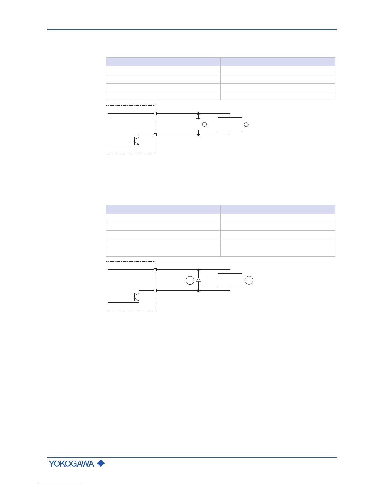
Transmitter
General Instruction Manual
Wiring
IM 01U10B00-00EN-R, 3rd edition, 2018-07-09
57 / 90
Active pulse
output P/Sout
Connection of an electronic counter
Maximum voltage and correct polarity must be observed for wiring.
Value
Load resistance > 1 kΩ
Internal power supply 24 VDC ±20 %
Maximum pulse rate 10000 pulses/s
Frequency range 0 – 12.5 kHz
P/Sout+
P/Sout-
24 V
0 V
ROTAMASS
2
1
Fig.41: Active pulse output connection P/Sout
① Load resistance
② Electronic counter
Connection of an electromechanical counter
Value
Maximum current 150 mA
Average current ≤ 30 mA
Internal power supply 24 VDC ±20 %
Maximum pulse rate 2 pulses/s
Pulse width 20, 33, 50, 100 ms
P/Sout+
P/Sout-
24 V
0 V
1
ROTAMASS
2
Fig.42: Active pulse output P/Sout connection with electromechanical counter
① Protective diode
② Electromechanical counter
Page 58

General Instruction Manual
Wiring
Transmitter
58 / 90
IM 01U10B00-00EN-R, 3rd edition, 2018-07-09
Active pulse
output P/Sout
with internal
pull-up resistor
Value
Internal power supply 24 VDC ±20 %
Internal pull-up resistor 2.2 kΩ
Maximum pulse rate 10000 pulses/s
Frequency range 0 – 12.5 kHz
P/Sout+
P/Sout-
24 V
0 V
ROTAMASS
1
Fig.43: Active pulse output P/Sout with internal pull-up resistor
① Electronic counter
Passive pulse
output P/Sout
Maximum voltage and correct polarity must be observed for wiring.
Value
Maximum load current ≤ 200 mA
Power supply ≤ 30 V
DC
Maximum pulse rate 10000 pulses/s
Frequency range 0 – 12.5 kHz
ROTAMASS
P/Sout+
P/Sout-
2
1
3
Fig.44: Passive pulse output connection P/Sout with electronic counter
① Passive pulse or status output
② Load resistance
③ Electronic counter
ROTAMASS
P/Sout+
P/Sout-
3
2
1
Fig.45: Passive pulse output P/Sout connection with electromechanical counter
① Passive pulse or status output
② Protective diode
③ Electromechanical counter
Page 59

Transmitter
General Instruction Manual
Wiring
IM 01U10B00-00EN-R, 3rd edition, 2018-07-09
59 / 90
Active status
output P/Sout
Since this is a transistor contact, maximum allowed current as well as polarity and level of
output voltage must be observed during wiring.
Value
Load resistance > 1 kΩ
Internal power supply 24 VDC ±20 %
P/Sout+
P/Sout-
24 V
0 V
ROTAMASS
1
Fig.46: Active status output connection P/Sout
① External device with load resistance
Active status
output P/Sout
with internal
pull-up resistor
Value
Internal pull-up resistor 2.2 kΩ
Internal power supply 24 VDC ±20 %
P/Sout+
P/Sout-
24 V
0 V
ROTAMASS
1
Fig.47: Active status output P/Sout with internal pull-up resistor
① External device
Page 60

General Instruction Manual
Wiring
Transmitter
60 / 90
IM 01U10B00-00EN-R, 3rd edition, 2018-07-09
Passive status
output P/Sout
or Sout
Value
Output current ≤ 200 mA
Power supply ≤ 30 V
DC
P/Sout+ or Sout+
P/Sout- or Sout-
ROTAMASS
1
Fig.48: Passive status output connection P/Sout or Sout
① External device
P/Sout- or Sout-
P/Sout+ or Sout+
ROTAMASS
2
1
3
4
Fig.49: Passive status output connection P/Sout or Sout for solenoid valve circuit
① Relay
② Solenoid valve
③ Magnetic valve power supply
④ Protective diode
A relay must be connected in series to switch alternating voltage.
Passive pulse
or status output
P/Sout (NAMUR)
Output signals according to EN 60947-5-6 (previously NAMUR, worksheet NA001):
10kΩ
1kΩ
ROTAMASS
P/Sout+
P/Sout-
2
1
Fig.50: Passive pulse or status output with switching amplifier connected in series
① Passive pulse or status output
② Switching amplifier
Page 61

Transmitter
General Instruction Manual
Wiring
IM 01U10B00-00EN-R, 3rd edition, 2018-07-09
61 / 90
7.4.6 Input signals
Active current
input lin
An individual analog power input is available for external analog devices.
The active current input lin is provided for connecting a two-wire transmitter with an output signal of 4–20 mA.
Value
Nominal input current 4 – 20 mA
Maximum input current range 2.4 – 21.6 mA
Internal power supply 24 VDC ±20 %
Internal load resistance Rotamass ≤ 160 Ω
Iin+
Iin-
24 V
ROTAMASS
0 V
1
Fig.51: Connection of external device with passive current output
① External passive current output device
Passive current
input lin
The passive current input lin is provided for connecting a four-wire transmitter with an output signal of 4 – 20 mA.
Value
Nominal input current 4 – 20 mA
Maximum input current range 2.4 – 21.6 mA
Maximum input voltage ≤ 32 V
DC
Internal load resistance Rotamass ≤ 160 Ω
Iin+
Iin-
ROTAMASS
1
Fig.52: Connection of external device with active current output
① External active current output device
Page 62

General Instruction Manual
Wiring
Transmitter
62 / 90
IM 01U10B00-00EN-R, 3rd edition, 2018-07-09
Status input Sin
Do not connect a signal source with electric voltage.
The status input is provided for use of voltage-free contacts with the following specification:
Switching status Resistance
Closed < 200 Ω
Open > 100 kΩ
ROTAMASS
Sin+
Sin-
Fig.53: Status input connection
7.4.7 Power supply
Power supply
Alternating-current voltage (rms):
▪ Power supply1): 24 VAC +20 % -15 % or 100–240 VAC +10 % -20 %
▪ Power frequency: 47–63Hz
Direct-current voltage:
▪ Power supply1): 24 VDC +20 % -15 % or 100–120 VDC +8,3 % -10 %
1)
for option MC␣ (DNV GL approval) supply voltage is limited to 24 V
Power consumption
P ≤ 10 W (including sensor)
Power supply
failure
In the event of a power failure, the flow meter data are backed up on a non-volatile internal memory. In case of devices with display, the characteristic sensor values, such as
nominal diameter, serial number, calibration constants, zero point, etc. and the error history are also stored on a microSD card.
Page 63

Transmitter
General Instruction Manual
Wiring
IM 01U10B00-00EN-R, 3rd edition, 2018-07-09
63 / 90
7.4.8 Connecting power supply and external devices
WARNING
Risk of sparking and damage to the flow meter due to incorrect sealing
▶ In case of metric cable entry ensure appropriate IP rating and suitability of O-ring of
used accessory (e.g. cable glands).
▶ In case of NPT cable entry ensure appropriate sealing measures (e.g. use of sealing
tape).
NOTICE
Risk of damage to the flow meter due to incorrect power supply
▶ The specified power supply must be observed (see General Specifications).
▶ The power-supply cable must be designed for the power supply used with a
minimum diameter of 0.5 mm.
2
1
1 Transmitter back cover
2 Power supply cable gland
WARNING
Risk of injury due to electrical shock
▶ The transmitter must be assigned an external, fixed-mount power switch or automatic
circuit breaker in order to disconnect the transmitter from the power grid (compliant
with IEC60947-1 and IEC60947-3). Power switch or automatic circuit breaker must
disconnect all lines under current, but cannot disconnect the grounding conductor
under any circumstances.
▶ The power switch of automatic circuit breaker must be installed near the transmitter
and easily accessible. The "OFF" switch position must be clearly recognizable.
Page 64
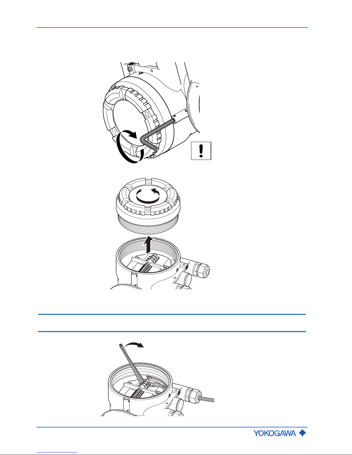
General Instruction Manual
Wiring
Transmitter
64 / 90
IM 01U10B00-00EN-R, 3rd edition, 2018-07-09
1. Switch off power supply.
2. Using an Allen wrench (Size: 3.0), tighten the locking screw on the back cover in
clockwise direction.
3. Unscrew back cover from transmitter housing in counter-clockwise direction.
4. Attach cable glands.
5. Connect wires to connection terminals.
NOTICE
Connect the grounding conductor to the grounding screw (see chapter Connection
terminals [}51], figure, point 2).
Page 65
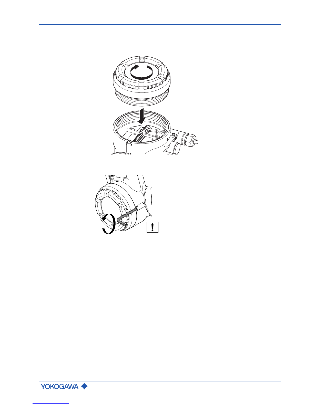
Transmitter
General Instruction Manual
Wiring
IM 01U10B00-00EN-R, 3rd edition, 2018-07-09
65 / 90
6. Fit grounding conductor with a terminal lug and affix to grounding conductor.
7. Screw cable gland on tightly.
8. Screw back cover onto transmitter housing in clockwise direction.
9. Using an Allen wrench (Size: 3.0), loosen the locking screw in counter-clockwise
direction.
Page 66

General Instruction Manual
Wiring
Wiring check list
66 / 90
IM 01U10B00-00EN-R, 3rd edition, 2018-07-09
7.5 Wiring check list
The following checks must be performed once the flow meter is connected electrically:
WARNING
Risk of injury from electrical shock due to insufficiently closed housing
▶ Before switching on the power supply, check that the housing covers of the transmit-
ter have been properly installed.
WARNING
Risk of sparking and damage to the flow meter due to missing locking
screw
▶ After wiring work, check that the housing cover has been installed and the locking
screws have been tightened.
NOTICE
Risk of damage to the flow meter due to insufficiently secured cable inlets
▶ Install cables tension-free.
▶ Fit any unused cable entries with blind plugs.
▶ Completely install cable glands and screw together tightly.
NOTICE
Be aware that improper treatment of cable entry and/or cable terminal may lead to disturbance of other sensitive electrical equipment due to increased electromagnetic emissions.
Check Performed?
Are cables intact?
Are power-supply and signal cables connected correctly?
Do the cables have a lower point where liquid can drip immediately
before they enter the cable glands?
Are the cables installed tension-free?
Is the power supply within the range specified on the nameplate?
Are any unused cable entries fitted with blind plug?
Are cable glands installed completely, tightly secured and watertight?
Are housing covers installed and locking screws tightened?
Page 67

General Instruction Manual
Commissioning
IM 01U10B00-00EN-R, 3rd edition, 2018-07-09
67 / 90
8 Commissioning
1. Activate external power switch.
2. Perform check of piping installation.
3. Check flow meter for device errors, warnings or alarms,
see chapter on Troubleshooting [}80].
4. Configure the transmitter, and perform autozero,
see chapter on Default settings [}72].
ð Flow meter is ready for operation.
Page 68
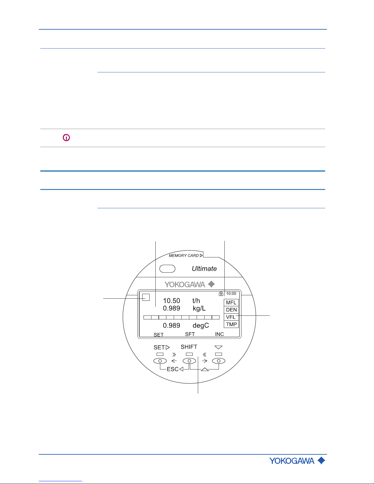
General Instruction Manual
System configuration and operation
Operating options
68 / 90
IM 01U10B00-00EN-R, 3rd edition, 2018-07-09
9 System configuration and operation
9.1 Operating options
The Rotamass Total Insight can be operated in different ways:
▪ IR (Infra-Red) switches on the display
▪ Digital communication (e.g. HART or Modbus)
The section below describes how to operate the system using the IR switches on the display.
The display is a device option and therefore not always available.
For more information on how to operate the transmitter and its functions, and on digital
communication, see applicable software instruction manual.
NOTICE
Be aware that all covers are closed before operating in order to prevent disturbance of
other sensitive electrical equipment due to increased electromagnetic emissions.
9.2 Display
All of the functions described here are also available via digital communication. Numerical
values that are entered via the display are limited to 6 digits.
1 2
3
5
4
Fig.54: Display layout
1 Measured quantities and units 4 IR switches
2 Status icon and time 5 Alarm symbol
3 Measured quantity abbreviation
Page 69
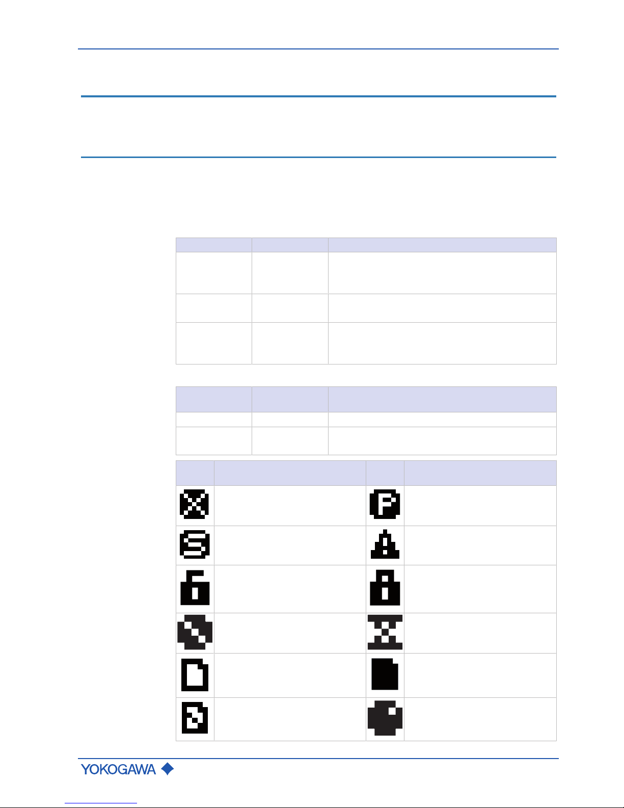
Display
General Instruction Manual
System configuration and operation
IM 01U10B00-00EN-R, 3rd edition, 2018-07-09
69 / 90
The controls on the display are IR switches. They respond as soon as an object, such as
a finger, is in close proximity. It is not necessary to apply pressure to the display surface.
NOTICE
Impairment of the display
If the device is operated for a longer period and is subjected to high temperatures or high
humidity in the process, the display may be impaired.
▶ Replace display unit as described in Rotating and replacing the display [}33]
Observe the following instructions to ensure that the IR switches are functional:
▶ Keep the display glass clean.
▶ Avoid exposure to direct sunlight.
▶ To increase the reflectivity of fingers (e.g. if they are very dirty) place some white tape
on the fingertip.
IR switch functions
IR switch Display Function
SET ► SET
▪ Apply setting
▪ Enter data
▪ Apply parameter
SHIFT SHT
▪ Move cursor right or to the next position
▪ Change function and display of SET and ▼
▼ INC
▪ Increment parameter or value
▪ Change position of the decimal point
▪ Select next menu item
The IR switch function changes as follows when used with the SHIFT key:
Key
combinations
Display Function
SHIFT + SET ► ESC
▪ Cancel and switch to parent menu
SHIFT + ▼ DEC
▪ Decrement parameter or number
▪ Select previous menu item
Status icons
Status
icon
Description Status
icon
Description
System alarm tripped Process alarm tripped
Settings alarm tripped Warning tripped
Write protection disabled Write protection enabled
Device error (no write access) Device busy (no write access)
microSD card ready Access to microSD card
Error accessing microSD card Process variable has bad status
Page 70
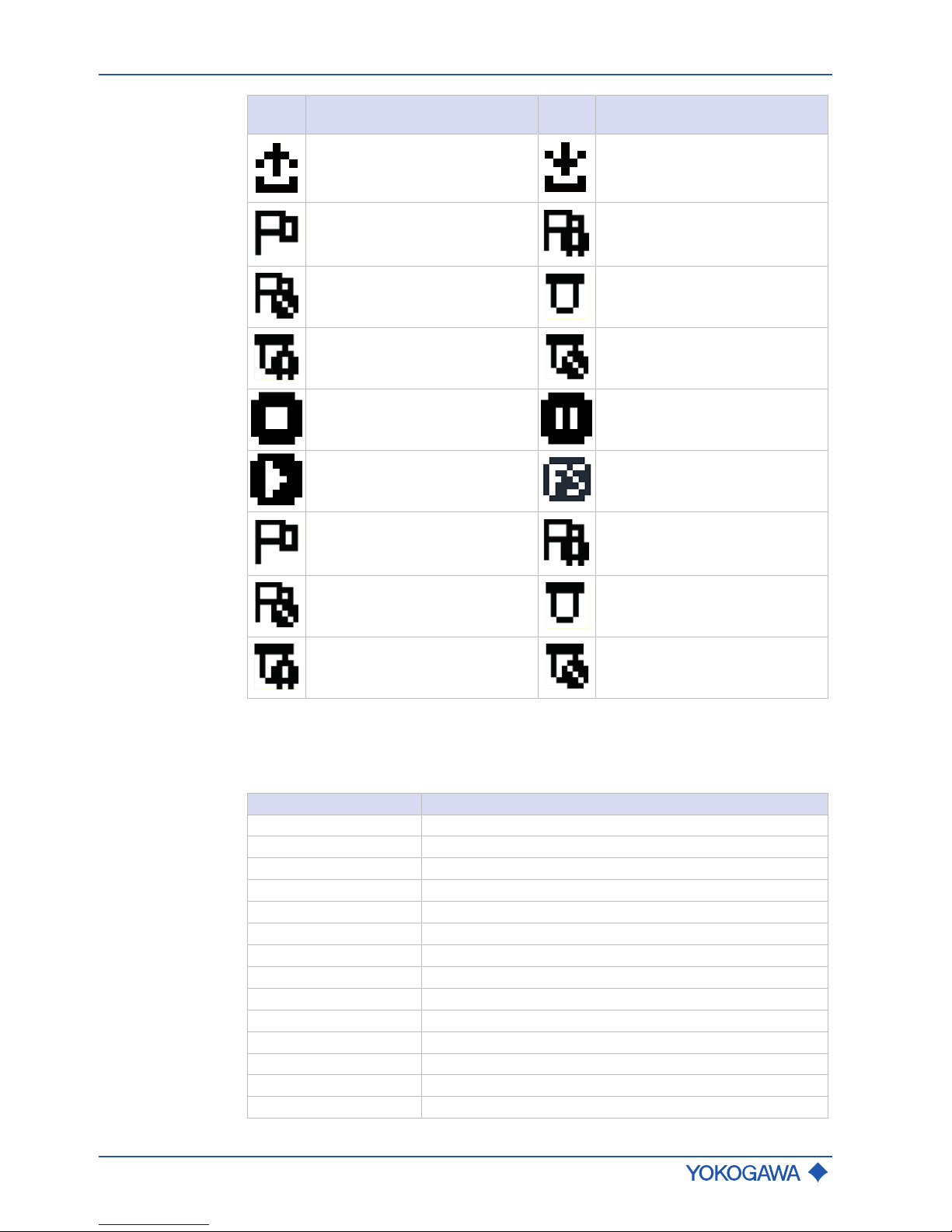
General Instruction Manual
System configuration and operation
Display
70 / 90
IM 01U10B00-00EN-R, 3rd edition, 2018-07-09
Status
icon
Description Status
icon
Description
Upload parameter enabled Download parameter enabled
Total health result: good
(only indicated when display total
health result is active)
Total health result: warning
(only indicated when display total
health result is active)
Total health result: bad state
(only indicated when display total
health result is active)
Tube health check with result: OK
Tube health check with result:
warning
Tube health check with result: error
Stop batch Resume batch
Batch running SIL mode
Total health result: good
(only indicated when display total
health result is active)
Total health result: warning
(only indicated when display total
health result is active)
Total health result: bad state
(only indicated when display total
health result is active)
Tube health check with result: OK
Tube health check with result:
warning
Tube health check with result: error
For status icon placement on the display see figure at Display [}68], No. 1, 2 or 5.
Measured quantities
and identifications
List of measured quantity abbreviations and identification on the display
Tab.1: Regular display
Abbreviation Measured quantity or identification
MFL Mass flow
DNS Density
TMP Temperature
VFL Volume flow
RFD Reference density
RLD Relative density
CVF Corrected volume flow
PRS Pressure
TT1 – TT6 Totalizer 1 – 6
TAG Customer-Device identification
LTG Customer-Device identification, long version
VEL Velocity
CNC Concentration
NM1, NM2 Net mass flow rate 1, 2
Page 71

Display
General Instruction Manual
System configuration and operation
IM 01U10B00-00EN-R, 3rd edition, 2018-07-09
71 / 90
Abbreviation Measured quantity or identification
NV1, NV2 Net volume flow rate 1, 2
NCV Corrected net volume flow rate
DRC Drive current
VSC Viscosity
HT1 24hours totalizer 1
HT2 24hours totalizer 2
HT3 24hours totalizer 3
GVF Gas void fraction
Page 72

General Instruction Manual
System configuration and operation
Default settings
72 / 90
IM 01U10B00-00EN-R, 3rd edition, 2018-07-09
The following values are only available for the trend display to record data on the microSD card. Additional information about data recording can be found in the applicable
software instruction manual.
Only use the microSD card included with the Rotamass Total Insight. Functionality of the
device cannot be guaranteed if other cards are used.
Tab.2: Trend display
Abbreviation Measured quantity or identification
MFL Mass flow
DNS Density
TMP Temperature
VFL Volume flow
PRS Pressure
CNC Concentration
NM1 Net mass flow rate 1
NV1 Net volume flow rate 1
PHS Phase shift
FRQ Resonance frequency
DRG Drive gain
DRC Driving current
MBT Transmitter temperature
VSC Viscosity
9.3 Default settings
9.3.1 Setting display language
1. Press [SET] switch for 2 seconds to enter [Operation level].
2. Press [▼] switch 1 time to enter [Operator].
3. Press [SET] switch to enter [Device setup].
4. Press [▼] switch until [Lang] is selected.
5. Press [SET] switch to enter the [Lang] menu.
6. Press [▼] switch repeatedly until the desired language appears.
7. Press [SET] switch to select the desired language.
8. Press [SET] switch to confirm the language selected.
ð Display switches to the next higher menu level.
Page 73

Default settings
General Instruction Manual
System configuration and operation
IM 01U10B00-00EN-R, 3rd edition, 2018-07-09
73 / 90
9.3.2 Setting date
1. Press [SET] switch for 2 seconds to enter [Operation level].
2. Press [▼] switch until the [Maintenance] menu is selected.
3. Press [SET] switch to enter the [Device setup] menu.
4. Press [▼] switch until the [Detailed setup] menu is selected.
5. Press [SET] switch to enter the [Detailed setup] menu.
6. Press [▼] switch until the [Date/Time] menu is selected.
7. Press [SET] switch to enter the [Date/Time] menu.
ð Menu [Date] is preselected.
8. Press [▼] switch until the menu [Set date] is selected.
9. Press [SET] switch to enter the menu [set date].
ð Date on display is flashing.
10. Press [▼]switch until the desired year is displayed.
11. Press [SHIFT] switch to switch to the display of the month.
12. Press [▼] switch until the desired month is displayed.
13. Press [SHIFT] switch to switch to the display of the day.
14. Press [▼]switch until the desired day is displayed.
15. Press [SET] switch to apply the date set.
16. Press [SET]switch to confirm the date set.
ð Display switches to the next higher menu level.
9.3.3 Setting time
1. Press [SET]switch for 2 seconds to enter [Operation level].
2. Press [▼] switch until the [Maintenance] menu is selected.
3. Press [SET] switch to enter [Device setup].
4. Press [▼] switch until the [Detailed setup] menu is selected.
5. Press [SET] switch to enter [Detailed setup].
6. Press [▼] switch until the [Date/Time] menu is selected.
7. Press [SET] switch to enter [Date/Time].
8. Press [▼] switch until the [Set time] menu is selected.
9. Press [SET] switch to enter [Set time].
ð Time on display is flashing.
10. Press [▼] switch until the desired number for the hour is displayed.
11. Press [SHIFT] switch to set the minutes.
12. Repeat the two previous steps for minutes and seconds.
13. Press [SET] switch to apply the time set.
14. Press [SET] switch to confirm the time set.
ð Display switches to the next higher menu level.
Page 74

General Instruction Manual
System configuration and operation
Default settings
74 / 90
IM 01U10B00-00EN-R, 3rd edition, 2018-07-09
9.3.4 Setting zero point
In order to avoid systematic flow rate measurement deviations, performance of a zero
point adjustment is recommended before starting measuring operations. For two- or multiphase fluids, the factory-set zero point value is preferable to a manual zero point adjustment.
1. Flush flow meter with fluid and check valves for tightness.
2. Close valves in front of and after the flow meter and stop the flow.
3. Wait until density, temperature and pressure are stabilized.
4. In case of fluids, compare the density displayed on the Rotamass Total Insight with
the fluid density in order to rule out gas accumulations in the measuring tube.
5. In applications with increased process pressure, ensure that the process pressure
and its unit of measurement are set correctly.
6. Perform autozero.
9.3.5 Performing autozero
To ensure ideal measuring results, performance of a second autozero process is recommended after several days of operation and stabilization of the installation conditions.
1. Press [SET] switch for 2 seconds to enter [Operation level].
2. Press [▼] switch until the [Operator] menu is selected.
3. Press [SET] switch to enter [Device setup].
4. Press [▼] switch until the [Diag/Service] menu is selected.
5. Press [SET] switch to enter [Diag/Service].
6. Press [▼] switch until the [AZ] menu is selected.
7. Press [SET] switch to enter [AZ].
ð Menu [Exe] is preselected.
8. Press [SET] switch to enter [Exe].
ð Parameter [Not exe] appears.
9. Press [▼] switch until [Exe] is selected.
10. Press [SET] switch.
ð Parameter [Exe] flashes.
11. Press [SET] switch to start autozero.
ð Progress bar appears to indicate status of autozero, after completion display
switches to next higher menu level.
Page 75

Advanced settings
General Instruction Manual
System configuration and operation
IM 01U10B00-00EN-R, 3rd edition, 2018-07-09
75 / 90
9.4 Advanced settings
DANGER
Explosion hazard
▶ When the housing is opened in hazardous areas, the applicable Explosion Proof
Type Manual must be observed, see chapter Operation, maintenance and repair.
9.4.1 Setting hardware write-protection
The flow meter can be protected from unauthorized access. If the software write-protection via password is not adequate, an additional hardware write-protection can be set on
the main board of the transmitter. With the write-protection active, the transmitter display
can still be operated, any changes to settings or parameters are not saved and therefore
not effective.
Write-protection can also be activated without removing the display. To do this, remove
the jumper from the write-protection terminal (see Connection terminals [}51]).
It is not possible to release the hardware write-protection via HART, Modbus or other
communication software.
1. Switch off power supply.
2. Loosen the locking screw by turning it clockwise with an Allen wrench (size: 3.0).
3. Unscrew display cover from transmitter housing.
Page 76

General Instruction Manual
System configuration and operation
Advanced settings
76 / 90
IM 01U10B00-00EN-R, 3rd edition, 2018-07-09
4. On the main board, set DIP switch 2 to the ON position using a sharp-pointed object.
OFF
1 2
H
L
SW1
ON
5. Screw display cover back onto transmitter housing.
6. Tighten the locking screw by turning it counterclockwise with an Allen wrench (size:
3.0).
ð Symbol appears in the top right corner of the display.
Setting the Burnout mode
The flow meter is equipped with a Burnout function. The Burnout mode can be set via
DIP SW1-1 behind the display.
Factory setting
The factory setting of the Burnout mode is High.
SW1-1 position Burnout mode Output value if Burnout
in mA
High 21.6
Low 2.4
Page 77

Advanced settings
General Instruction Manual
System configuration and operation
IM 01U10B00-00EN-R, 3rd edition, 2018-07-09
77 / 90
9.4.2 MODBUS hardware setting
Switch settings
1. Switch off power supply.
2. Loosen the locking screw by turning it clockwise with an Allen wrench (size: 3.0).
Fig.55:
3. Unscrew display cover from transmitter housing.
4. Remove 2 screws from the display.
Page 78

General Instruction Manual
System configuration and operation
Advanced settings
78 / 90
IM 01U10B00-00EN-R, 3rd edition, 2018-07-09
5. Remove the display from housing by slowly pulling forward.
ð The switch can be seen.
6. Set the desired address.
OFF
1 2
H
L
SW1
ON
0
3
1
0
127
6
5
4
Address
1 2
ON
OFF
1 2
SW2SW3
7. Push display into housing.
8. Fasten the display with 2 screws.
9. Screw display cover back onto transmitter housing.
10. Tighten the locking screw by turning it counterclockwise with an Allen wrench (size:
3.0).
Page 79

Advanced settings
General Instruction Manual
System configuration and operation
IM 01U10B00-00EN-R, 3rd edition, 2018-07-09
79 / 90
Default settings
Switches
Address SW 3 SW 2
0 ON OFF
Address switch
SW (ADDRESS: 7)
Device address Position Description
Hardware 1
Address SW” settings between position 0 and 6 are the
device address.
Software 0
Parameter value setting is the device address.
Factory setting
SW (ADDRESS: 0-6)
Hardware address can be set from 1 to 127.
e.g.: If only address switch "6" is set to 1, the resulting address is 64.
(1 * 26 + 0 * 25 + 0 * 24 + 0 * 23 + 0 * 22 + 0 * 21 + 0 * 20)
Address has to be set always between 1 and 127. If address switch is set to 0, address is
automatically converted to 1.
When hardware switch is active, then address value based on the hardware address is
stored in the device.
SW2
Line termination of two ends on the bus are required to communicate Modbus. One termination mode can be selected by SW2, see below table for setting.
Termination mode Configuration
Bus end
Available when both SW2-1 and SW2-2 are “ON”
(Resistance is 150 Ω)
Not bus end Available when both SW2-1 and SW2-2 are “OFF”
Both SW2-1 and SW2-2 have to be set at the same position.
SW3
When bus is idle state, it becomes unstable in potential without pull up to D1 and pull
down to D0. SW3 can be set, see below table for setting.
Pull up and Pull down mode Configuration of Pull up and Pull down
Used
Available when both SW3-1 and SW3-2 are “ON”
(Resistance is 600 Ω)
Not used Available when both SW3-1 and SW3-2 are “OFF”
Both SW3-1 and SW3-2 have to be set at the same position.
Page 80

General Instruction Manual
Troubleshooting
Malfunction of operation
80 / 90
IM 01U10B00-00EN-R, 3rd edition, 2018-07-09
10 Troubleshooting
All error messages and error codes that may appear in operation are described in the
software instruction manual. Possible malfunctions that may occur during commissioning
are explained below and remedying them is explained. If you cannot remedy the malfunction using these explanations, contact the Yokogawa service center.
10.1 Malfunction of operation
Malfunction Possible causes Remedy
Display on
transmitter not
functioning
Power supply
disconnected
– Ensure that the unit is connected to the
power supply, see [}63]
Settings cannot be
made via IR switches
– Check cable connections between
display and main board and connect
properly, if necessary.
Settings cannot
be made via IR
switches
Incorrect settings in
write-protect menu
item
– Switch off write-protect menu item via
digital communication or hardware
switch.
Field communicator is not detected
HART or Modbus DD
not installed on field
communicator
– Save HART or Modbus DD file on field
communicator.
Field communicator
not connected
– Connect field communicator with
Rotamass Total Insight, see software
instruction manual.
Page 81

Zero point unstable
General Instruction Manual
Troubleshooting
IM 01U10B00-00EN-R, 3rd edition, 2018-07-09
81 / 90
10.2 Zero point unstable
Malfunction Possible causes Remedy
Zero point
unstable
Measuring tube not
completely filled with
fluid
– Check that the measuring tube in the
sensor is completely filled with fluid.
Correct installation, see [}21].
Bubbles or solids in
the fluid
– Check pipe and sensor installation,
see [}27].
– Correct installation, see [}21].
No electrical
grounding
– Ground transmitter and sensor,
see [}44], and [}63].
– Check correct connection of connecting
cable shield on transmitter.
Flow meter installed in
proximity to facilities
with strong electromagnetic field
– Ground transmitter and sensor,
see [}44], and [}63].
– Install flow meter as far away as possible
from these electric devices.
Mechanical strain
from traction or
pressure
– Eliminate cause for mechanical tension.
Terminal board or
connection terminals
of transmitter or
sensor soiled or damp
– Clean terminal board and connection
terminals.
– Clean transmitter and/or sensor.
– Dry transmitter and/or sensor.
– Seal transmitter and/or sensor tightly.
Influence of external
vibration
– Install mechanical dampers.
– Increase parameter mass flow damping
(see applicable software instruction
manual).
Page 82

General Instruction Manual
Troubleshooting
Display deviating
82 / 90
IM 01U10B00-00EN-R, 3rd edition, 2018-07-09
10.3 Display deviating
Malfunction Possible causes Remedy
Flow rate displayed deviates
from actual flow
rate
Zero point set
incorrectly
– Set zero point, see [}74]
Highest and lowest
value for mass flow
set incorrectly
– Match settings of flow meter and reading
system.
– Check LRV and URV process parame-
ters, see software instruction manual.
Measuring tubes not
completely filled with
fluid
– Correct installation, see [}27]
Bubbles in fluid
– Check pipe and installation, see [}27].
– Correct installation, see [}27]
Connecting cable incorrectly connected
for remote type
– Check cable connections and correct, if
necessary, see [}46].
Density displayed
deviating from
actual density
Density unit, highest
and lowest value for
density set incorrectly
– Match settings of flow meter and reading
system.
– Check LRV and URV process parame-
ters, see software instruction manual.
Fixed density
– Check whether the Val sel parameter is
set correctly. If a fixed value is selected,
ensure that the parameter Fix val is set
correctly, see software instruction
manual.
– Set parameter Val sel to Meas val,
see software instruction manual.
Analog output trim
was performed incorrectly
– Correctly perform trimming, see
applicable software instruction manual.
No electrical
grounding
– Ground transmitter and sensor,
see [}44].
– Check correct connection of connecting
cable shield on transmitter.
Bubbles in fluid
– Check pipe and installation, see [}27].
Connecting cable incorrectly connected
for remote type
– Check cable connections and correct, if
necessary, see [}46].
Faulty temperature
measurement
– Check temperature measurement circuits
TP1 – TP3 of connecting cable.
Corrosion and erosion
– If corrosion or erosion due to corrosive
fluids is suspected, contact Yokogawa
and have density and mass flow recalibrated, if necessary.
Contaminated
measuring tubes
– Clean measuring tubes.
Page 83

Display deviating
General Instruction Manual
Troubleshooting
IM 01U10B00-00EN-R, 3rd edition, 2018-07-09
83 / 90
Malfunction Possible causes Remedy
Temperature displayed deviating
from actual temperature
Temperature unit,
highest and lowest
value for temperature
set incorrectly
– Match settings of flow meter and reading
system.
– Check LRV and URV process parame-
ters, see software instruction manual.
Non-adjustable
temperature
– Check whether the Func sel parameter is
set correctly. If a fixed value is selected,
ensure that the Fix val is set correctly,
see software instruction manual.
– Set parameter Func sel to Inter val.
Analog output trim
was performed incorrectly
– Correctly perform trimming (see applica-
ble software instruction manual).
Connecting cable incorrectly connected
for remote type
– Check cable connections and correct, if
necessary, see [}46].
Incorrect temperature
measurement with
remote type
– Check temperature measurement circuit
by measuring resistance between TP1/
TP2 and TP1/TP3. Each value must be
between 50 – 200 Ω.
– Check temperature measurement circuit
TP2/TP3 and make sure that resistance
is < 10 Ω.
– Connect Pt100 simulator and check
temperature measurement.
Output signal
deviating from
measured quantity
Incorrect parameter
– Check parameter LRV and URV of the
corresponding output signal, and correct,
if necessary.
Incorrect measured
quantity
– Check measured quantity output and, if
necessary, correct; check parameter Sel,
see software instruction manual.
Page 84

General Instruction Manual
Maintenance and repair
84 / 90
IM 01U10B00-00EN-R, 3rd edition, 2018-07-09
11 Maintenance and repair
Applicable country-specific regulations for opening and repairing electrical devices must
be observed.
DANGER
Risk of injury and damage to the flow meter due to ignition after sparking,
if there is mechanical impact
▶ Avoid strong mechanical impacts on the flow meter during maintenance work.
WARNING
Risk of injury due to electrical shock, as well as damage to the flow meter,
due to insufficiently trained personnel
▶ Only have skilled personnel maintain and repair the flow meter.
WARNING
Risk of injury due to electrical shock, as well as damage to the flow meter
▶ Do not perform maintenance outdoors during rain.
WARNING
Risk of injury from slipping or falling flow meter
▶ Observe notes about the transport of the flow meter in chapter Transport [}19];
these also apply accordingly during maintenance work.
WARNING
Risk of injury due to electrical shock, as well as damage to the flow meter,
due to maintenance work in areas at risk of explosion
▶ When maintaining the flow meter in areas at risk of explosion, compliance with the
applicable Explosion Proof Type Manual is mandatory.
WARNING
Risk of injury from electrical shock due to insufficiently closed housing
▶ After completion of the maintenance work, check that the housing covers of the
transmitter have been properly installed.
WARNING
Risk of open/ close the transmitter cover
▶ Please be sure to handle the transmitter cover carefully so that there are no dam-
ages and foreign matter adhesion at its thread and O-ring when it is opened or
closed. Keep checking their condition and clean the threads in case of adhering the
foreign matter. Replace the cover in case the threads receive damages. Replace the
O-ring if there is any scarring or transformation and apply silicone based grease at
the O-ring in case of the shortage and exhaustion of grease.
NOTICE
Risk of damage to the flow meter due to electrostatic discharge (ESD)
▶ When performing maintenance work on the flow meter, appropriate ESD protective
measures must be taken.
NOTICE
Be aware that all covers are closed before operating in order to prevent disturbance of
other sensitive electrical equipment due to increased electromagnetic emissions.
The need for maintaining the Rotamass Total Insight depends on process and environmental conditions. Maintenance-free operation is possible for many processes. Contact
the responsible Yokogawa sales organization for details.
Page 85

Exterior cleaning
General Instruction Manual
Maintenance and repair
IM 01U10B00-00EN-R, 3rd edition, 2018-07-09
85 / 90
11.1 Exterior cleaning
WARNING
Risk of injury due to electrical shock, as well as damage to the flow meter,
due to unskilled cleaning
▶ For CIP or SIP cleaning, limit the steam temperature to max. 230°C.
▶ Observe the maximum permissible ambient temperature for the transmitter during
cleaning (especially for the integral type).
1. Regularly remove soiling on display glass pane or nameplate by using a soft, dry
cloth.
2. Use only cleaning agents that do not corrode the surface of the flow meter.
11.2 Recalibration and calibration service
For recalibration, flow meters should be sent to the manufacturer Rota Yokogawa GmbH
in Wehr/Germany. The option of having on-site calibration performed by a Yokogawa
technician is available in some countries. For additional information regarding service
products and their availability, go to the Yokogawa homepage or contact a local
Yokogawa sales partner.
11.3 Impairment of the display
NOTICE
Impairment of the display
If the device is operated for a longer period and is subjected to high temperatures or high
humidity in the process, the display may be impaired.
▶ Replace display unit as described in Rotating and replacing the display [}33]
11.4 List of replacement parts
Replacement parts may be reordered using the Customer Maintenance Part List (CMPL),
which is available on the included CD/ DVD.
Page 86

General Instruction Manual
Dismantling and disposal
Decontamination and return shipment
86 / 90
IM 01U10B00-00EN-R, 3rd edition, 2018-07-09
12 Dismantling and disposal
12.1 Decontamination and return shipment
DANGER
Use of fluids that are a health hazard may result in caustic burns or
poisoning
▶ When removing the flow meter, avoid touching the fluid and breathing gas residues
left in the sensor.
▶ Wear protective clothing and a breathing mask.
Note the following items before returning the shipment:
▶ Clean flow meter thoroughly. No harmful chemicals must remain in or on the flow me-
ter. Rota Yokogawa only accepts completely drained and cleaned flow meters.
▶ The form "Decontamination Declaration" must be filled in completely and sent to
Yokogawa along with the flow meter.
▶ Package flow meter in a shockproof manner for transport. Use original packaging, if
possible.
12.2 Disposal
Prior to disposal of the flow meter, please take note of the following:
▶ Comply with the applicable national regulations in the event of disposal or recycling.
▶ Do not dismantle flow meter until all fluid residues have been removed and dispose
the parts individually.
Page 87

ROTA YOKOGAWA GmbH & Co. KG
Service & Repair Department
Rheinstraße 8; D - 79664 Wehr
Phone no.: +49 (0)7761-567-190
Fax no.: +49 (0)7761-567-285
e-Mail: services.flow@de.yokogawa.com
Declaration of Decontamination
Legal regulations for the safety of our employees and operating equipment determine that we need
the declaration of decontamination before your order can be handled.
Please make sure to include it with the shipping documents, attached to the outside of the
packaging you use for shipment.
Customer data
Company:
Address:
Contact person: E-Mail:
Phone no.: Fax no.:
Reference/Order no.:
Instrument data
*
Type:
Serial no.:
Type: Serial no.:
*If not enough, note on separate sheet
Process data
:
Process fluid:
Fluid is:
[ ] toxic
[ ] corrosive
[ ] explosive
[ ] biological hazardous
[ ] unknown if dangerous
[ ] non hazardous
Remarks:
Cleaning agent:
Kind of cleaning :
Other remarks / Reason of retur
n:
We hereby confirm that this statement is filled in completely and truthfully. The returned
instruments were carefully cleaned and are thus free from product residue and dirt. I agree
that if this arrangement does not match with the instruments, they will be sent back to the
above mentioned customer address at our expenses.
Name Date Signature
Page 88

General Instruction Manual
Specifications
Ambient conditions
88 / 90
IM 01U10B00-00EN-R, 3rd edition, 2018-07-09
13 Specifications
Specifications for sensor and transmitter are listed in the General Specifications of the
corresponding product family.
13.1 Ambient conditions
Rotamass Total Insight can be used at demanding ambient conditions.
In doing so, the following specifications must be taken into account:
As ambient temperature is intend the air surrounding the device.
Allowed ambient and storage temperature of Rotamass Total Insight depends on the below components and their own temperature limits:
▪ Sensor
▪ Transmitter
▪ Connecting cable between sensor and transmitter (for remote design type)
Ambient
temperature
Maximum ambient temperature range
1)
integral type: -40–60 °C (-40–140 °F)
remote type
with standard cable
(option L␣␣␣):
Sensor2): -50–80 °C (-58–176 °F)
Transmitter: -40–60 °C (-40–140 °F)
with fire retardant cable
3)
(option Y␣␣␣):
Sensor2): -35–80 °C (-31–176 °F)
Transmitter: -35–60 °C (-31–140 °F)
1)
If the device is operating outdoors make sure that the solar irradiation does not increase
the surface temperature of the transmitter higher than the allowed maximum ambient
temperature. Transmitter display has limited legibility below -20 °C (-4°F)
2)
Check derating for high fluid temperature, see Process fluid temperature range,
Process conditions and Allowed ambient temperatures for sensor.
3)
Lower temperature specification valid for fixed installation only
Storage
temperature
Maximum storage temperature range
integral type -40–60 °C (-40–140 °F)
remote type
with standard cable
(option L␣␣␣):
Sensor: -50–80 °C (-58–176 °F)
Transmitter: -40–60 °C (-40–140 °F)
with fire retardant cable
(option Y␣␣␣):
Sensor: -35–80 °C (-31–176 °F)
Transmitter: -35–60 °C (-31–140 °F)
Further
ambient conditions
Ranges and specifications
Relative humidity 0–95 %
IP code
IP66/67 for transmitters and sensors when
using the appropriate cable glands
Allowable pollution degree in surrounding
area acc. EN61010-1
4 (in operation)
Vibration resistance acc. IEC 60068-2-6
Transmitter: 10 – 500 Hz, 1g
Sensor: 25– 100 Hz, 4g
Page 89

Ambient conditions
General Instruction Manual
Specifications
IM 01U10B00-00EN-R, 3rd edition, 2018-07-09
89 / 90
Ranges and specifications
Electromagnetic compatibility (EMC)
▪ IEC/EN 61326-1, Table 2
▪ IEC/EN 61326-2-3
▪ NAMUR NE 21 recommendation
▪ DNVGL-CG-0339, chapter 14
This includes
▪ Surge immunity acc.:
– EN 61000-4-5 for lightning
protection
▪ Emission acc.:
– IEC/EN 61000-3-2, Class A
– IEC/EN 61000-3-3, Class A
– NAMUR NE 21 recommendation
– DNVGL-CG-0339, chapter 14
Immunity assessment criterion:
The output signal fluctuation is within ±1%
of the output span.
Maximum altitude
2000m (6600ft) above mean sea level
(MSL)
Overvoltage category acc. IEC/EN61010-1 II
Page 90

YOKOGAWA ELECTRIC CORPORATION
YOKOGAWA CORPORATION OF AMERICA
YOKOGAWA AMERICA DO SUL LTDA.
YOKOGAWA EUROPE B. V.
Euroweg 2, 3825 HD Amersfoort,
THE NETHERLANDS
Phone : 31-88-4641000
Fax : 31-88-4641111
YOKOGAWA INDIA LTD.
Plot No.96, Electronic City Complex,
Hosur Road, Bangalore - 560 100,
INDIA
Phone : 91-80-4158-6000
Fax : 91-80-2852-1442
YOKOGAWA AUSTRALIA PTY. LTD.
Tower A, 112-118 Talavera Road,
Macquarie Park NSW 2113,
AUSTRALIA
Phone : 61-2-8870-1100
Fax : 61-2-8870-1111
YOKOGAWA MIDDLE EAST & AFRICA B.S.C.(C)
P.O. Box 10070, Manama, Building 577,
Road 2516, Busaiteen 225, Muharraq,
Kingdom of BAHRAIN
Phone : 973-17358100
Fax : 973-17336100
Headquarters
2-9-32, Nakacho, Musashino-shi,
Tokyo, 180-8750 JAPAN
Phone : 81-422-52-5555
Branch Sales Offices
Osaka, Nagoya, Hiroshima,
Kurashiki, Fukuoka, Kitakyusyu
Head Office
12530 West Airport Blvd, Sugar Land,
Texas 77478, USA
Phone : 1-281-340-3800
Fax : 1-281-340-3838
Georgia Office
2 Dart Road, Newnan, Georgia 30265, USA
Phone : 1-800-888-6400/ 1-770-253-7000
Fax : 1-770-254-0928
Praca Acapulco, 31 - Santo Amaro, Sáo Paulo/SP,
BRAZIL, CEP-04675-190
Phone : 55-11-5681-2400
Fax : 55-11-5681-4434
YOKOGAWA ELECTRIC CIS LTD.
Grokholskiy per 13 Building 2, 4th Floor 129090,
Moscow, RUSSIA
Phone : 7-495-737-7868
Fax : 7-495-737-7869
YOKOGAWA CHINA CO., LTD.
3F Tower D Cartelo Crocodile Building,
No.568 West Tianshan Road,
Shanghai 200335, CHINA
Phone : 86-21-62396262
Fax : 86-21-62387866Z
YOKOGAWA ELECTRIC KOREA CO., LTD.
(Yokogawa B/D, Yangpyeong-dong 4-Ga),
21, Seonyu-ro 45-gil, Yeongdeungpo-gu,
Seoul, 150-866, KOREA
Phone : 82-2-2628-6000
Fax : 82-2-2628-6400
YOKOGAWA ENGINEERING ASIA PTE. LTD.
5 Bedok South Road, Singapore 469270,
SINGAPORE
Phone : 65-6241-9933
Fax : 65-6241-2606
ISO 9001
IM 01U10B00-00EN-R, 3rd edition, 2018-07-09
All rights reserved. Copyright © 2018-07-09
 Loading...