

Page 1

User’s
Manual
M Series
Digital Limit Alarms
Communication Functions
IM 77J04J11-01E
IM 77J04J11-01E
1st Edition
Page 2

Blank Page
Page 3

<Toc> <Ind> <Rev>
Introduction
This user's manual describes the communication functions of the M Series digital limit
alarms (hereinafter simply referred to as M Series) and contains information on how to
create communication programs.
Read the manual carefully to understand the communication functions of the M Series.
The M Series have the following communication protocols.
● PC link communication protocol
● MODBUS communication protocol
● Ladder communication protocol
Note that the M Series cannot communicate with a higher-level device with a communication protocol other than these.
You are required to have background knowledge of the communication specifications of
higher-level devices, their communication hardware, language used for creating communication programs, and so on.
i
■ Intended Readers
This manual is intended for people familiar with the functions of the M Series, control
engineers and personnel in charge of maintaining instrumentation and control equipment.
■ Related Documents
The following user's manuals all relate to the communication functions of the M Series.
Read them as necessary.
● Model MVHK Digital Limit Alarm (DC Input Type)
Document number: IM 77J04H31-01E
● Model MVRK Digital Limit Alarm (RTD Input Type)
Document number: IM 77J04R31-01E
● Model MVTK Digital Limit Alarm (Thermocouple Input Type)
Document number: IM 77J04T31-01E
The user's manuals above describe mounting, wiring, and how to operate the digital
limit alarms.
Media No. IM 77J04J11-01E (MO) 1st Edition : 2006.08.25 (YK)
All Rights Reserved Copyright © 2006, Yokogawa Electric Corporation
IM 77J04J11-01E 1st Edition : 2006.08.25-00
Page 4

<Toc> <Ind> <Rev>
Documentation Conventions
■ Symbols
The following symbols are used in this manual.
● Symbols Used in the Main Text
CAUTION
Draws attention to information that is essential for understanding the operation and/or
features of the product.
TIP
Gives additional information to complement the present topic.
See Also
ii
Gives reference locations for further information on the topic.
■ Description of Displays
(1) Some of the representations of product displays shown in this manual may be exag-
gerated, simplified, or partially omitted for reasons of convenience when explaining
them.
(2) Although, figures and illustrations representing the digital limit alarm's displays may
differ from the real displays in regard to the position and/or indicated characters
(upper-case or lower-case, for example), the extent of difference does not impair a
correct understanding of the functions and the proper operations and monitoring of the
system.
IM 77J04J11-01E 1st Edition : 2006.08.25-00
Page 5

<Toc> <Ind> <Rev>
Notices
■ Regarding This User's Manual
(1) This manual should be passed on to the end user. Keep the manual in a safe place.
(2) Read this manual carefully to gain a thorough understanding of how to operate this
product before you start using it.
(3) This manual is intended to describe the functions of this product. Yokogawa Electric
Corporation (hereinafter simply referred to as Yokogawa) does not guarantee that
these functions are suited to the particular purpose of the user.
(4) Under absolutely no circumstance may the contents of this manual, in part or in whole,
be transcribed or copied without permission.
(5) The contents of this manual are subject to change without prior notice.
(6) Every effort has been made to ensure accuracy in the preparation of this manual.
Should any errors or omissions come to your attention however, please contact your
nearest Yokogawa representative or our sales office.
iii
■ Regarding Protection, Safety, and Prohibition Against Unauthorized
Modification
(1) In order to protect the product and the system controlled by it against damage and
ensure its safe use, be certain to strictly adhere to all of the instructions and precautions relating to safety contained in this document. Yokogawa does not guarantee
safety if products are not handled according to these instructions.
(2) The following safety symbols are used on the product and/or in this manual.
● Symbols Used on the Product and in This Manual
CAUTION
This symbol on the product indicates that the operator must refer to an explanation in
the user's manual in order to avoid the risk of injury or death of personnel or damage
to the instrument. The manual describes how the operator should exercise special
care to avoid electric shock or other dangers that may result in injury or loss of life.
Protective Grounding Terminal
This symbol indicates that the terminal must be connected to ground prior to operating
the equipment.
Functional Grounding Terminal
This symbol indicates that the terminal must be connected to ground prior to operating
the equipment.
IM 77J04J11-01E 1st Edition : 2006.08.25-00
Page 6

<Toc> <Ind> <Rev>
■ Force Majeure
(1) Yokogawa does not make any warranties regarding the product except those men-
tioned in the WARRANTY that is provided separately.
(2) Yokogawa assumes no liability to any party for any loss or damage, direct or indirect,
caused by the use or any unpredictable defect of the product.
(3) Be sure to use the spare parts approved by Yokogawa when replacing parts or
consumables.
(4) Modification of the product is strictly prohibited.
(5) Reverse engineering such as the disassembly or decompilation of software is strictly
prohibited.
(6) No portion of the software supplied by Yokogawa may be transferred, exchanged,
leased or sublet for use by any third party without the prior permission of Yokogawa.
iv
IM 77J04J11-01E 1st Edition : 2006.08.25-00
Page 7

<Int> <Ind> <Rev>
M Series Digital Limit Alarms
Communication Functions
CONTENTS
Introduction........................................................................................................... i
Documentation Conventions ...............................................................................ii
Notices .................................................................................................................iii
1. Setup ....................................................................................................... 1-1
1.1 Setup Procedure ............................................................................................. 1-1
1.2 Notes on Setting Parameters ......................................................................... 1-2
2. Communication Specifications.............................................................. 2-1
2.1 RS-485 Communication Specifications ......................................................... 2-1
Toc-1
IM 77J04J11-01E 1st Edition
3. PC Link Communication ........................................................................ 3-1
3.1 Overview.......................................................................................................... 3-1
3.1.1 Configuration of Command ............................................................... 3-2
3.1.2 Configuration of Response ............................................................... 3-3
3.1.3 Response Error Codes ..................................................................... 3-4
3.1.4 Specifying Broadcast ........................................................................ 3-5
3.2 Commands ...................................................................................................... 3-6
3.2.1 List of Commands ............................................................................. 3-6
BRD Reads I relays on a bit-by-bit basis ......................................... 3-7
BWR
Writes data into I relays on a bit-by-bit basis ........................... 3-8
BRR Reads I relays on a bit-by-bit basis in random order ................ 3-9
BRW
Writes data into I relays on a bit-by-bit basis in random order ..
BRS Specifies I relays to be monitored on a bit-by-bit basis ........... 3-11
BRM Monitors I relays on a bit-by-bit basis .................................... 3-12
WRD
Reads D registers and I relays on a word-by-word basis ....... 3-13
WWR
Writes data into D registers and I relays on a word-by-word
basis..................................................................................... 3-14
WRR
Reads D registers and I relays on a word-by-word basis in
random order ........................................................................ 3-15
WRW
Writes data into D registers and I relays on a word-by-word
basis in random order ........................................................... 3-16
WRS
Specifies D registers and I relays to be monitored on a word-
by-word basis ....................................................................... 3-17
WRM
Monitors D registers and I relays on a word-by-word basis.... 3-18
INF Reads the model, range code number, number of alarms and
revision ................................................................................. 3-19
3-10
IM 77J04J11-01E 1st Edition : 2006.08.25-00
Page 8

<Int> <Ind> <Rev>
4. Ladder Communication.......................................................................... 4-1
5. MODBUS Communication...................................................................... 5-1
Toc-2
3.3 Communication with Higher-level Devices ................................................. 3-20
3.3.1 Example of Communication Program Created Using Visual Basic .. 3-21
3.3.2 Communication with UT Link Module .............................................. 3-25
3.3.3 Communication with Touch Panel ................................................... 3-26
4.1 Overview.......................................................................................................... 4-1
4.2 Commands/Responses at the PLC ................................................................ 4-2
4.2.1 Configuration of Command/Response .............................................. 4-2
4.2.2 Reading Parameters......................................................................... 4-3
4.2.3 Writing Parameters ........................................................................... 4-4
4.2.4 Response Error Codes ..................................................................... 4-5
5.1 Overview.......................................................................................................... 5-1
5.1.1 Configuration of Message ................................................................. 5-2
5.1.2 Specifying D Registers...................................................................... 5-3
5.2 Function Codes ............................................................................................... 5-4
5.2.1 List of Function Codes ...................................................................... 5-4
03 Reads data from multiple D registers ...................................... 5-5
06 Writes data into a D register.................................................... 5-7
08 Performs loop back test .......................................................... 5-9
16 Writes data into multiple D registers ...................................... 5-10
5.2.2 Response Error Codes ................................................................... 5-12
5.2.3 Specifying Broadcast ...................................................................... 5-13
6. Functions and Usage of D Registers ..................................................... 6-1
6.1 Overview of D Registers ................................................................................. 6-1
6.2 Interpretation of D Register Map Table .......................................................... 6-1
6.3 D Register Map Table ...................................................................................... 6-2
6.3.1 Contents of D Registers .................................................................... 6-3
7. Functions and Usage of I Relays ........................................................... 7-1
7.1 Status............................................................................................................... 7-2
Appendix Table of ASCII Codes (Alphanumeric Codes).........................App.-1
Revision Information ............................................................................................ i
IM 77J04J11-01E 1st Edition : 2006.08.25-00
Page 9
<Toc> <Ind> <1. Setup >
1. Setup
This chapter describes the setup procedure required to use the communication
functions (PC link, Ladder and MODBUS) and the communication parameters of the
M Series.
1.1 Setup Procedure
Set up the communication functions on the M Series as follows:
Set up the communication function parameters of the M Series. (See section 1.2.)
Connect a higher-level device and a M Series. (See the connection diagram below.)
Create communication programs for the higher-level device to perform communication.
Note: Refer to the documentation of each higher-level device when creating communication programs.
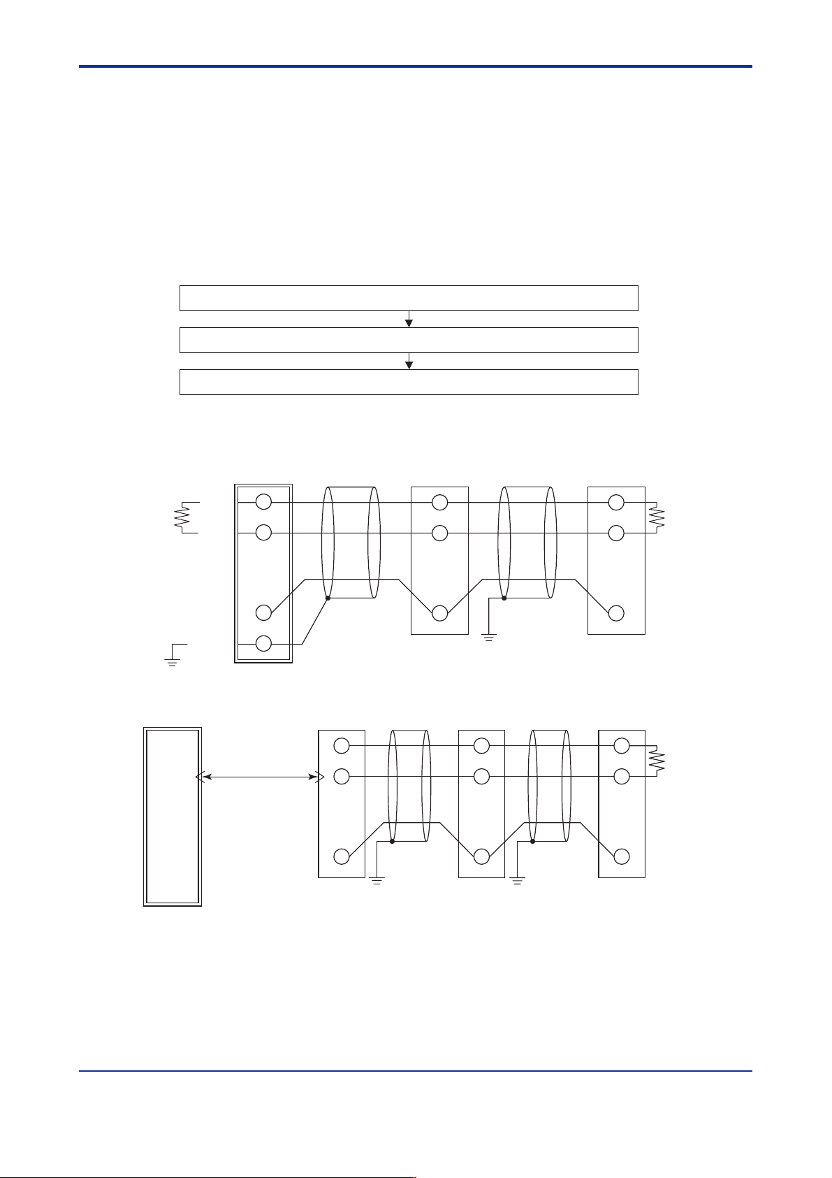
• Connection
PLC
B (+)
A (-)
Terminating resistor
220 Ω
1/4 W
M Series M Series
B (+)
A (-)
1
2
B (+)
A (-)
1
2
1-1
Terminating resistor
220 Ω
1/4 W
SG
Shielded
JIS Class D grounding
(grounding resistance of 100 Ω or less)
PC or PLC
(straight cable)
(RS-232C/RS-485 converter)
RS-232C
ML2
B (+)
4
A (-)
3
5
SG
JIS Class D grounding
(grounding resistance
of 100 Ω or less)
3
JIS Class D grounding
(grounding resistance of 100 Ω or less)
M Series M Series
B (+)
1
A (-)
2
3
JIS Class D grounding
(grounding resistance
of 100 Ω or less)
COMCOM
B (+)
A (-)
COMCOM
3
1
2
Terminating resistor
3
220 Ω
1/4 W
IM 77J04J11-01E 1st Edition : 2006.08.25-00
Page 10
<Toc> <Ind> <1. Setup >
1.2 Notes on Setting Parameters
This section describes the setting parameters for using the communication functions and their setting ranges.
CAUTION
The details of M Series communication functions need to be the same as those of the
communication functions of the higher-level device to be connected. Check the communication parameters of the higher-level device first, then set up those of the M Series.
Table 1-1 Parameters to be Set for Communication Functions
1-2
Parameter Name
Protocol selection Without checksum (0)
Address
Baud rate
Parity
Stop bit
Data length
*1: When "Ladder communication" is selected in protocol selection, the data length is fixed to 8.
When "MODBUS communication" is selected, the data length is fixed to 7 for ASCII mode and to 8 for RTU mode.
Symbol
PSL
ADR
BPS
PRI
STP
DLN
Setting Range
PC link communication
With checksum (1)
MODBUS communication ASCII mode (3)
RTU mode (4)
Ladder (2)Ladder communication
1 to 99
1.2 (0), 2.4 (1), 4.8 (2), 9.6 (3) kbps
NON (0), EVN (1), ODD (2)
1, 2
7, 8 (*1)
PC link communication
without checksum
● Protocol selection (PSL)
Set the communication protocol identical to that of the higher-level device to be connected.
Default
(0)
1
9.6 (3)
EVN (1)
1
8
IM 77J04J11-01E 1st Edition : 2006.08.25-00
Page 11
<Toc> <Ind> <1. Setup >
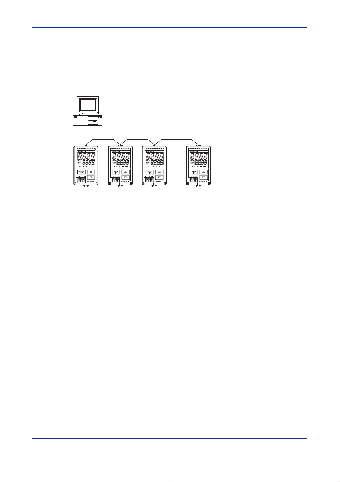
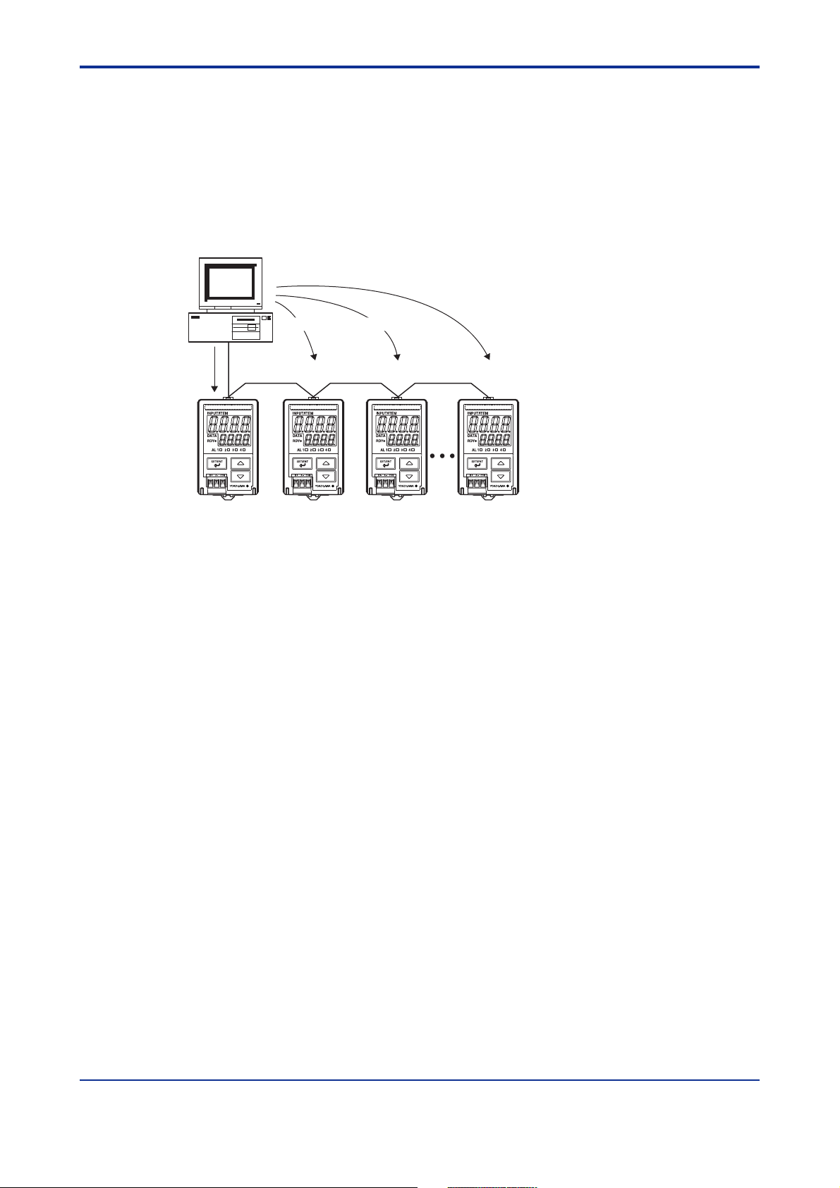
● Address number (ADR)
Set the address number of the M Series itself. An address number of 1 to 99 can be assigned in any order. Note that the number of M Series that can be connected to a single
communication port is limited to 31.
Example of connecting four M Series to a higher-level device by setting address numbers
of 1, 5, 10 and 20
PC
A maximum of 1200 m; up to 31 slave stations
1-3
ADR=1 ADR=20ADR=10ADR=5
● Baud rate (BPS)
Set the baud rate identical to that of the higher-level device to be connected. (Otherwise,
proper communication cannot be achieved.) The unit of the baud rate is kbps (kbits per
second).
● Parity (PRI)
Set the handling of parity to be carried out when data is sent or received. Set the parity bit
state identical to that of the higher-level device to be connected.
● Stop bit (STP)
Set the stop bit identical to that of the higher-level device to be connected.
● Data length (DLN)
Set the data length identical to that of the higher-level device to be connected. (When
Ladder or MODBUS communication is selected in protocol selection, the data length is
fixed.)
IM 77J04J11-01E 1st Edition : 2006.08.25-00
Page 12

Blank Page
Page 13

<Toc> <Ind> <2. Communication Specifications >
2. Communication Specifications
The RS-485 communication interface has the PC link communication, Ladder communication and MODBUS communication protocols.
Table 2-1 M Series Communication Specifications
2-1
Communication Hardware
Terminal
Communication Protocol
Specifications
Maximum Baud Rate
Table 2-2 Types of Devices to be Connected
Connected Device
PC
PC, touch panel and PLC
(FA-M3 UT link module)
PLC (sequencer) (FA-M3
ladder communication module)
2-wire RS-485 communication system
Two-piece connector on the front panel: 1, 2, 3
PC link communication without checksum
PC link communication with checksum
MODBUS communication (ASCII mode)
MODBUS communication (RTU mode)
Ladder communication
9600 bps
Communication Protocol
MODBUS communication
PC link communication
Ladder communication
Example of Connected Device
General-purpose PC
General-purpose PC, FA-M3
and GP Series
General-purpose PLC
(sequencer)
2.1 RS-485 Communication Specifications
Table 2-3 RS-485 Communication Interface
Item
Compliant standard EIA, RS-485
Maximum number of devices to be connected 31
Communication system
Synchronization Asynchronous (start-stop)
Maximum communication distance 1200 m
Baud rate 1200, 2400, 4800, 9600
2-wire, half duplex
No handshakingCommunication method
Specifications
IM 77J04J11-01E 1st Edition : 2006.08.25-00
Page 14

Blank Page
Page 15
<Toc> <Ind> <3. PC Link Communication >
3. PC Link Communication
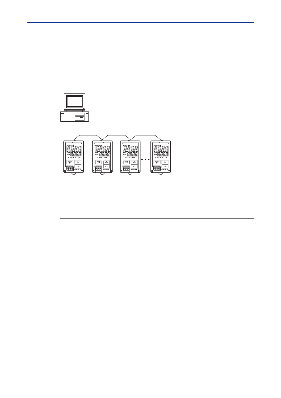
3.1 Overview
The use of PC link communication enables the M Series to communicate with a
device such as a PC, graphic panel and FA-M3 UT link module easily. In this communication, you can use such device to read/write data from/into D registers or I relays,
both of which are internal registers of the M Series.
PC
A maximum of 1200 m; up to 31 slave stations
3-1
Figure 3-1 Example of Connection for PC Link Communication
Hereafter, PCs etc. are generically called "higher-level devices."
See Also
Chapters 6 and 7 for information on the D registers and I relays.
In PC link communication, a higher-level device identifies each M Series with an address
number, which ranges from 01 to 99.
IM 77J04J11-01E 1st Edition : 2006.08.25-00
Page 16

<Toc> <Ind> <3. PC Link Communication >
3.1.1 Configuration of Command
Commands sent from a higher-level device to the M Series consist of the following elements.
3-2
Number of Bytes 1 2 2 1 3 2 1 1
Element STX Address
number
(ADR)
(1) (2) (3) (4) (5) (7) (8) (9)(6)
CPU
number
01
Time to wait
for response
0
Command Data
Variable length
Checksum ETX CR
corresponding
to command
(1) STX (Start of Text)
This control code indicates the start of a command. The ASCII code is 02 in hexadecimal.
(2) Address Number (01 to 99)
Adress numbers are used by a higher-level device to identify the M Series at the
communication destination. (Identification numbers specific to individual M Series.)
(3) CPU Number
This is fixed to 01.
(4) Time to Wait for Response
This is fixed to 0.
(5) Command (See subsection 3.2.)
This specifies a command to be issued from the higher-level device.
(6) Data Corresponding to Command
This specifies an internal register (D register or I relay), number of data pieces and
others.
(7) Checksum
This converts the ASCII codes of texts between the character next to STX and the
character immediately before the checksum into hexadecimal values and adds them
byte by byte. It then fetches the single lowermost byte of the added results as the
checksum.
This column is only required for PC link communication with checksum. PC link
communication without checksum does not require this 2-byte space of ASCII code.
(8) ETX (End of Text)
This control code indicates the end of a command string. The ASCII code is 03 in
hexadecimal.
(9) CR (Carriage Return)
This control code indicates the end of a command. The ASCII code is 0D in hexadecimal.
CAUTION
The control codes STX, ETX and CR are essential for commands when you create a
communication program for PC link communication. Omission of any of them or incorrect
order of them results in communication failure.
IM 77J04J11-01E 1st Edition : 2006.08.25-00
Page 17

<Toc> <Ind> <3. PC Link Communication >
3.1.2 Configuration of Response
Responses from the M Series with respect to a command sent from the higher-level device
consist of the following elements, which differ depending on the condition of communication; normal or failure.
1) Normal Communication
If communication succeeded, a character string "OK" is returned with the data corresponding to a command.
Number of Bytes Variable length12 22 211
Element STX Address
number
(ADR)
CPU
number
01
2) In the Event of Failure
If communication failed, a character string "ER" is returned with error codes (EC1 and
EC2). (See subsection 3.1.3, "Response Error Codes.")
• No response is returned in case of an error in address number specification or CPU
number specification.
• If ETX in a command cannot be received, a response may not be returned.
Note: As a countermeasure, provide a timeout process in the communication functions of the higher-level device or in
communication programs.
Number of Bytes 1 2 2 2 2 2 3 2 1 1
Element STX ER EC1 EC2 Command Checksum ETX CRAddress
number
(ADR)
CPU
number
01
OK Parameter data Checksum ETX CR
3-3
IM 77J04J11-01E 1st Edition : 2006.08.25-00
Page 18

<Toc> <Ind> <3. PC Link Communication >
3.1.3 Response Error Codes
See Also
3.1.2, "Configuration of Response", for the structure of response in the event of error.
The error codes (EC1) and detailed error codes (EC2) of responses are as follows.
Table 3-1 List of Error Codes EC1
Error Code Meaning Cause(s)
02
03
04
05
Command error
Register specification error
Out of setpoint range
Out of data count range
• No command exists.
• Command not executable
• No register number exists.
• Invalid specification of bit register (I relay) when it is used on a word basis
• Any character other than 0 or 1 is used for bit setting.
• A value other than 0000 to FFFF has been specified in word specification.
• The position of a start for a data load is out of the address range.
• The specification of the number of bits, words, etc. is out of the range of
use.
• The number of data specified and that of parameters for registers and
others are not consistent.
3-4
06 • An attempt was made to execute monitoring without specifying the
43 Internal buffer overflow
44 • The end-of-data or end-of-text character has not been received.
Monitor error
Sum error
Character reception interval
timeout
monitor (BRS or WRS).
• An illegal parameter is set. 08 Parameter error
• The sum does not match the expected value. 42
• A data value greater than the specified was received.
Table 3-2 List of Detailed Error Codes EC2
Error Code (EC1)
03
04
05
08 Parameter error • An illegal parameter is set.
Register specification error
Out of setpoint range
Out of data count range
Meaning
Detailed Error Code (EC2)
Parameter number where error occurred (HEX)
This is the sequence number of a parameter that first resulted in an error
when counted from the leading parameter.
e.g.: Register specification error
[STX]01010BRR02I0001,D0001[ETX][CR]
Parameter numbers
[STX]0101ER0303BRR[ETX][CR]
1 2 3
↓
For error codes other than those noted as EC1, there is no EC2 meaning.
IM 77J04J11-01E 1st Edition : 2006.08.25-00
Page 19
<Toc> <Ind> <3. PC Link Communication >
3.1.4 Specifying Broadcast
Broadcast addressing allows the corresponding multiple M Series to receive the command.
(1) To use this function, specify BM for the address number in a command.
(2) Broadcast addressing works independently of the address number.
(3) Broadcast addressing is only applicable to write commands.
(4) No response is returned if broadcast addressing is used.
Higher-level device (master)
Broadcast data.
* No response from slaves
A maximum of 1200 m; up to 31 slave stations
3-5
For the M Series communication, D registers and I relays are used.
IM 77J04J11-01E 1st Edition : 2006.08.25-00
Page 20

<Toc> <Ind> <3. PC Link Communication >
3.2 Commands
3.2.1 List of Commands
The following shows lists of commands available in PC link communication. Their details
are explained in the description of each command.
(1) Bit-basis Access Commands Dedicated to I Relays
Command Description Number of Bits to be Handled
BRD
BWR Bit-basis write 1 to 256 bits
BRR Bit-basis random read
BRW Bit-basis random write 1 to 32 bits
BRS Specifies registers to be monitored on a bit-by-bit basis.
BRM
(2) Word-basis Access Commands
Command Description Number of Words to be Handled
WRD
WWR
WRR
WRW
WRS
WRM
Bit-basis read
Bit-basis monitoring
Word-basis read
Word-basis write
Word-basis random read
Word-basis random write
Specifies registers to be monitored on a word-by-word basis.
Word-basis monitoring
1 to 256 bits
1 to 32 bits
1 to 32 bits
1 to 64 words
1 to 64 words
1 to 32 words
1 to 32 words
1 to 32 words
3-6
(3) Information Command
Command Description Number of Units to be Handled
INF1Reads model, input range code, number of alarms
and revision.
IM 77J04J11-01E 1st Edition : 2006.08.25-00
Page 21

<Toc> <Ind> <3. PC Link Communication >
BRD Reads I relays on a bit-by-bit basis
● Function
Reads the ON/OFF statuses of a sequence of contiguous I relays by the specified number
of bits, starting at a specified I relay number.
• The number of bits to be read at a time is 1 to 256.
• For the format of response in the event of failure, see subsection 3.1.2.
• The command shown below includes the checksum function.
When performing communication without checksum, do not include the 2-byte
checksum element in the command.
● Command/Response (for normal operation)
Number of Bytes 1 2 2 1 3 5 1 3 2 1 1
Command
element
STX Address
number
(ADR)
CPU
number
01
0 BRD ETX CRI relay
number
Comma
or space
Number
of bits
(n)
Checksum
3-7
Number of Bytes
element
Responses 0 and 1 indicate OFF and ON respectively.
dn: read data of the specified number of bits (n=1 to 256)
dn=0 (OFF)
dn=1 (ON)
1 2 2 2111 1 2 1 1
CPU
STX Address
number
(ADR)
number
OK d1 d2 d3 ETX CRResponse
01
● Example:
Reading the status of alarm 1 of the M Series with address number 01.
The following command reads the status of alarm 1 (
[Command]
[STX]01010BRDI0001,00191[ETX][CR]
The following response is returned with respect to the above command. (Alarm 1 is ON.)
[Response]
[STX]0101OK18D[ETX][CR]
• • •
• • • dn Checksum
I0001) of address number 01.
Alarm has been ON since 1 was returned.
IM 77J04J11-01E 1st Edition : 2006.08.25-00
Page 22

<Toc> <Ind> <3. PC Link Communication >
BWR Writes data into I relays on a bit-by-bit basis
● Function
Writes ON/OFF data into a sequence of contiguous I relays by the specified number of bits,
starting at a specified I relay number.
• The number of bits to be written into at a time is 1 to 256.
• For the format of response in the event of failure, see subsection 3.1.2.
• The command shown below includes the checksum function.
When performing communication without checksum, do not include the 2-byte
checksum element in the command.
● Command/Response (for normal operation)
Number of Bytes 1 2 2 1 3 5 1 3 2 1 1
Command
element
Command (continued)
• • •
• • • dn Checksum ETX
STX Address
number
(ADR)
1
21CR1
CPU
number
01
0 BWR d1 d2I relay
number
Comma
or space
Number
of bits
(n)
Comma
or space
3-8
Write data 0 and 1 indicate OFF and ON respectively.
dn: write data of the specified number of bits (n=1 to 256)
dn=0 (OFF)
dn=1 (ON)
Number of Bytes 1 2 2 2 2 1 1
element
STX Address
number
(ADR)
number
CPU
01
OK ETX CRResponse
Checksum
● Example:
Setting the user-defined flag of the M Series with address number 01 to ON.
The following command writes ON into the user-defined flag (
[Command]
[STX]01010BWRI0033,001,106[ETX][CR]
Note: The user-defined flags are flags that the user can freely read/write.
OK is returned in response to the above command.
[Response]
I0033) of address number 01.
[STX]0101OK5C[ETX][CR]
IM 77J04J11-01E 1st Edition : 2006.08.25-00
Page 23

<Toc> <Ind> <3. PC Link Communication >
BRR Reads I relays on a bit-by-bit basis in random order
● Function
Reads the ON/OFF statuses of the individuaI I relays specified in random order by the
specified number of bits.
• The number of bits to be read at a time is 1 to 32.
• For the format of response in the event of failure, see subsection 3.1.2.
• The command shown below includes the checksum function.
When performing communication without checksum, do not include the 2-byte
checksum element in the command.
● Command/Response (for normal operation)
Number of Bytes 1 2 2 1 3 2 5 1 5 1
Command
element
Command (continued)
• • •
• • • I relay
STX Address
5211
number n
CPU
number
(ADR)
Checksum ETX CR
number
01
0 BRR Number
of bits
(n)
I relay
number 1
Comma
or space
I relay
number 2
3-9
Comma
or space
Number of Bytes • • • 112 2211 2 11
OK d1 d2 CR• • • dn Checksum ETX
Response
element
Responses 0 and 1 indicate OFF and ON respectively.
dn: read data of the specified number of bits (n=1 to 32)
dn=0(OFF)
dn=1(ON)
STX Address
number
(ADR)
CPU
number
01
● Example:
Reading the statuses of alarms 1 and alarm 2 of the M Series with address number 01.
The following command reads the statuses of alarm 1 (
address number 01.
[Command]
[STX]01010BRR02I0001,I00027B[ETX][CR]
The ON and OFF responses are returned for alarm1 and alarm 2 respectively with respect
to the above command.
[Response]
I0001) and alarm 2 (I0002) of
[STX]0101OK10BD[ETX][CR]
Alarm 1 has been ON.
IM 77J04J11-01E 1st Edition : 2006.08.25-00
Page 24

<Toc> <Ind> <3. PC Link Communication >
BRW Writes data into I relays on a bit-by-bit basis in random order
● Function
Writes ON/OFF data into the individual I relays specified in random order by the specified
number of bits.
• The number of bits to be written into at a time is 1 to 32.
• For the format of response in the event of failure, see subsection 3.1.2.
• The command shown below includes the checksum function.
When performing communication without checksum, do not include the 2-byte
checksum element in the command.
● Command/Response (for normal operation)
Number of Bytes 1 2 2 1 3 2 5 1 1 1
Command
element
Command (continued)
51
I relay
number 2
STX Address
Comma
or space
number
(ADR)
1
CPU
number
01
111
Comma
or space
0BRW d1Number
• • •
• • • Checksumd2 ETX CR
of bits
(n)
51
I relay
number n
I relay
number 1
Comma
or space
Comma
or space
12
dn
3-10
Comma
or space
Write data 0 and 1 indicate OFF and ON respectively.
dn: write data of the specified number of bits (n=1 to 32)
dn=0 (OFF)
dn=1 (ON)
Number of Bytes 1 2 2 2 2 1 1
OK CRChecksum ETX
Response
element
STX Address
number
(ADR)
CPU
number
01
● Example:
Setting the four user-defined flags (I0033, I0034, I0035 and I0036) of the M Series with
address number 05 to ON, OFF, OFF and ON respectively.
[Command]
[STX]05010BRW04I0033,1,I0034,0,I0035,0,I0036,17D[ETX][CR]
Note: The user-defined flags are flags that the user can freely read/write.
OK is returned in response to the above command.
[Response]
[STX]0501OK60[ETX][CR]
IM 77J04J11-01E 1st Edition : 2006.08.25-00
Page 25

<Toc> <Ind> <3. PC Link Communication >
BRS Specifies I relays to be monitored on a bit-by-bit basis
● Function
Specifies the I-relay numbers to be monitored on a bit-by-bit basis. Note that this command simply specifies I relays. Actual monitoring is performed by the BRM command after
the I relay numbers are specified by this command.
When the volume of data is large and you wish to increase the baud rate, it is effective to
use a combination of the BRS and BRM commands rather than just the BRR command.
If the power supply is turned off, the specified I-relay numbers will be erased.
• The number of I relays to be specified at a time is 1 to 32.
• For the format of response in the event of failure, see subsection 3.1.2.
• The command shown below includes the checksum function.
When performing communication without checksum, do not include the 2-byte
checksum element in the command.
● Command/Response (for normal operation)
Number of Bytes 1 2 2 1 3 2 5 1 5 1
Command
element
STX Address
number
(ADR)
CPU
number
01
BRS Comma
0 Number
of bits
(n)
I relay
number 1
or space
I relay
number 2
3-11
Comma
or space
Command (continued)
• • •
• • • I relay
Response
element
5211
number n
Checksum ETX CR
12 22 2 11Number of Bytes
STX Address
number
(ADR)
CPU
number
01
OK Checksum ETX CR
● Example:
Specifying that the burnout, alarm 1 and alarm 2 of the M Series with address number 01
are to be monitored.
(This command simply specifies the registers to be monitored.)
[Command]
[STX]01010BRS03I0007,I0001,I0002B9[ETX][CR]
OK is returned in response to the above command.
[Response]
[STX]0101OK5C[ETX][CR]
IM 77J04J11-01E 1st Edition : 2006.08.25-00
Page 26

<Toc> <Ind> <3. PC Link Communication >
BRM Monitors I relays on a bit-by-bit basis
● Function
Reads the ON/OFF statuses of the I relays that have been specified in advance by the
BRS command.
• Before executing this command, the BRS command must always be executed to
specify which I relays are to be monitored. If no relay has been specified, error code
06 is returned.
• For the format of response in the event of failure, see subsection 3.1.2.
• The command shown below includes the checksum function.
When performing communication without checksum, do not include the 2-byte
checksum element in the command.
● Command/Response (for normal operation)
Number of Bytes 1 2 2 1 3 2 1 1
Command
element
STX 0 BRM ETX CRAddress
number
(ADR)
CPU
number
01
Checksum
3-12
Number of Bytes 1 2 2 2 1 1 1 1 2 1 1
Response
element
Responses 0 and 1 indicate OFF and ON respectively.
dn: read data of the number of bits specified by the BRS command (n=1 to 32)
dn=0 (OFF)
dn=1 (ON)
STX OK d1 d2 d3 ETX CRAddress
number
(ADR)
CPU
number
01
• • •
• • • dn Checksum
● Example:
Monitoring the burnout, alarm 1 and alarm 2 of the M Series with address number 01 when
they have been specified to be monitored.
(This command reads the statuses of the I relays specified by the BRS command.)
[Command]
[STX]01010BRMA3[ETX][CR]
The ON/OFF statuses of the I relays are returned with respect to the above command.
[Response]
[STX]0101OK000EC[ETX][CR]
All have been OFF.
IM 77J04J11-01E 1st Edition : 2006.08.25-00
Page 27

<Toc> <Ind> <3. PC Link Communication >
WRD Reads D registers and I relays on a word-by-word basis
● Function
Reads a sequence of contiguous register data on a word-by-word basis by the specified
number of words, starting at a specified register number.
• The number of words to be read at a time is 1 to 64.
• For the format of response in the event of failure, see subsection 3.1.2.
• The command shown below includes the checksum function.
When performing communication without checksum, do not include the 2-byte
checksum element in the command.
● Command/Response (for normal operation)
Number of Bytes 1 2 2 1 3 5 1 2211
Command
element
STX Address
number
(ADR)
CPU
number
01
Register
number
Comma
or space
Number
of words
Checksum0 WRD ETX CR
(n)
3-13
Number of Bytes • • •12 2244 4 2 11
Response
element
The response is returned in a 4-digit character string (0000 to FFFF) in hexadecimal.
ddddn: read data of the specified number of words
ddddn is a character string in hexadecimal.
n=1 to 64
STX OK dddd1 dddd2 ETXAddress
number
(ADR)
CPU
number
01
• • • ddddn Checksum
CR
● Example:
Reading the alarm-1 setpoint (D0101) of the M Series with address number 01.
[Command]
[STX]01010WRDD0101,0172[ETX][CR]
The alarm-1 setpoint 500 (01F4 [HEX]) is returned in response to the above command
(50.0 is expressed as 500).
[Response]
[STX]0101OK01F437[ETX][CR]
500 in decimal (Alarm-1 setpoint [A1] is 50.0.)
IM 77J04J11-01E 1st Edition : 2006.08.25-00
Page 28

<Toc> <Ind> <3. PC Link Communication >
WWR Writes data into D registers and I relays on a word-by-word basis
● Function
Writes data into a sequence of contiguous registers on a word-by-word basis by the specified number of words, starting at a specified register number .
• The number of words to be written into at a time is 1 to 64.
• For the format of response in the event of failure, see subsection 3.1.2.
• The command shown below includes the checksum function.
When performing communication without checksum, do not include the 2-byte
checksum element in the command.-
● Command/Response (for normal operation)
Number of Bytes 1 2 2 1 3 5 1 2 1 4
Command
element
Command (continued)
4211
dddd2
STX Address
number
(ADR)
• • •
• • • Checksumddddn ETX CR
4
CPU
number
01
0 WWR Comma
Register
number
Comma
or space
Number
of words
(n)
or space
3-14
dddd1
Write data is specified in a 4-digit character string (0000 to FFFF) in hexadecimal.
ddddn: write data of the specified number of words
ddddn is a character string in hexadecimal.
n=1 to 64
Number of Bytes 1 2 2 2 2 1 1
OK CRChecksum ETX
Response
element
STX Address
number
(ADR)
CPU
number
01
● Example:
Writing 200 (00C8 [HEX]) into the alarm-1 setpoint (D0101) of the M Series with address
number 03.
[Command]
[STX]03010WWRD0101,01,00C88E[ETX][CR]
OK is returned in response to the above command.
[Response]
[STX]0301OK5E[ETX][CR]
IM 77J04J11-01E 1st Edition : 2006.08.25-00
Page 29

<Toc> <Ind> <3. PC Link Communication >
3-15
WRR Reads D registers and I relays on a word-by-word basis in random
order
● Function
Reads the statuses of the individul registers on a word-by-word basis specified in random
order by the specified number of words.
• The number of words to be read at a time is 1 to 32.
• For the format of response in the event of failure, see subsection 3.1.2.
• The command shown below includes the checksum function.
When performing communication without checksum, do not include the 2-byte
checksum element in the command.
● Command/Response (for normal operation)
Number of Bytes 1 2 2 1 3 2 5 1 5 1
Command
element
STX Address
number
(ADR)
CPU
number
01
0 WRR Number
of words
(n)
Register
number 1
Comma
or space
Register
number 2
Comma
or space
Command (continued)
• • •
Response
element
The response is returned in a 4-digit character string (0000 to FFFF) in hexadecimal.
ddddn: read data of the specified number of words
ddddn is a character string in hexadecimal.
n=1 to 32
5211
Register
number n
1 2 224 4 4 2 11Number of Bytes
STX Address
number
(ADR)
ETX CR• • • Checksum
CPU
number
01
OK dddd1 dddd2 ETX CR• • • ddddn Checksum
• • •
● Example:
Reading the alarm-1 setpoint (D0101) and alarm-2 setpoint (D0102) of the M Series with
address number 01.
[Command]
[STX]01010WRR02D0101,D010288[ETX][CR]
The alarm-1 setpoint 500 (01F4 [HEX]) and alarm-2 setpoint 500 (01F4 [HEX]) are returned with respect to the above command (50.0 is expressed as 500).
[Response]
[STX]0101OK01F401F4FC[ETX][CR]
500 in decimal
(Alarm-1 setpoint is 50.0.)
500 in decimal
(Alarm-2 setpoint is 50.0.)
IM 77J04J11-01E 1st Edition : 2006.08.25-00
Page 30

<Toc> <Ind> <3. PC Link Communication >
3-16
WRW Writes data into D registers and I relays on a word-by-word basis in
random order
● Function
Writes register data specified for each register into the registers specified in random order
by the specified number of words.
• The number of words to be written into at a time is 1 to 32.
• For the format of response in the event of failure, see subsection 3.1.2.
• The command shown below includes the checksum function.
When performing communication without checksum, do not include the 2-byte
checksum element in the command.
● Command/Response (for normal operation)
Number of Bytes 1 2 2 1 3 2 5 1 4 1
Command
element
STX Address
number
(ADR)
CPU
number
01
0 WRW dddd1Number
of words
(n)
Register
number 1
Comma
or space
Comma
or space
Command (continued)
51
Register
number 2
Write data is specified in a 4-digit character string (0000 to FFFF) in hexadecimal.
ddddn: write data of the specified number of words
ddddn is a character string in hexadecimal.
n=1 to 32
Number of Bytes 1 2 2 2 2 1 1
Response
Comma
or space
element
4
STX Address
number
(ADR)
• • •
• • • Checksumdddd2 ETX CR
CPU
number
51 11
Register
number n
OK CRChecksum ETX
01
Comma
or space
42
ddddn
● Example:
Writing 20.0 and 15.0 into the alarm-1 setpoint (D0101) and alarm-2 setpoint (D0102) of the M
Series with address number 10 respectively.
[Command]
[STX]10010WRW02D0101,00C8,D0102,00968F[ETX][CR]
200 in decimal
(Alarm-1 setpoint is 20.0.)
150 in decimal
(Alarm-2 setpoint is 150.0.)
OK is returned in response to the above command.
[Response]
[STX]1001OK5C[ETX][CR]
IM 77J04J11-01E 1st Edition : 2006.08.25-00
Page 31

<Toc> <Ind> <3. PC Link Communication >
3-17
WRS Specifies D registers and I relays to be monitored on a word-by-word
basis
● Function
Specifies the register numbers to be monitored on a word-by-word basis. Note that this
command simply specifies the registers. Actual monitoring is performed by the WRM
command after the register numbers are specified by this command.
When the volume of data is large and you wish to increase the baud rate, it is effective to
use a combination of the WRS and WRM commands rather than just the WRR command.
If the power supply is turned off, the specified register numbers will be erased.
• The number of words to be specified at a time is 1 to 32.
• For the format of response in the event of failure, see subsection 3.1.2.
• The command shown below includes the checksum function.
When performing communication without checksum, do not include the 2-byte
checksum element in the command.
● Command/Response (for normal operation)
Number of Bytes 1 2 2 1 3 2 5 1 5 1
Command
element
Command (continued)
• • •
element
STX Address
5211
Register
number n
STX Address
12 222 11Number of Bytes
number
(ADR)
number
(ADR)
CPU
number
01
ETX CR• • • Checksum
CPU
number
01
0 WRS
OK Checksum
Number
of words
Register
number 1
(n)
ETX CRResponse
Comma
or space
Register
number 2
Comma
or space
● Example:
Specifying that the alarm-1 setpoint and alarm-2 setpoint of the M Series with address
number 01 are to be monitored
(This command simply specifies the registers to be monitored.)
[Command]
[STX]01010WRS02D0101,D010289[ETX][CR]
CPU number: 01 D register numbers
OK is returned in response to the above command.
[Response]
[STX]0101OK5C[ETX][CR]
IM 77J04J11-01E 1st Edition : 2006.08.25-00
Page 32

<Toc> <Ind> <3. PC Link Communication >
WRM Monitors D registers and I relays on a word-by-word basis
● Function
Reads the register data that have been specified in advance by the WRS command.
• Before executing this command, the WRS command must always be executed to
specify which registers are to be monitored. If no register has been specified, error
code 06 is generated.
• For the format of response in the event of failure, see subsection 3.1.2.
• The command shown below includes the checksum function.
When performing communication without checksum, do not include the 2-byte
checksum element in the command.
● Command/Response (for normal operation)
Number of Bytes 1 2 2 1 3 2 1 1
Command
element
STX Address
number
(ADR)
CPU
number
01
Checksum0 WRM ETX CR
3-18
Number of Bytes
Response
element
The response is returned in a 4-digit character string (0000 to FFFF) in hexadecimal.
ddddn: read data of the number of words specified by the WRS command
ddddn is a character string in hexadecimal.
n=1 to 32
12 2244 4 2 11
STX OK dddd1 dddd2 ETX CRAddress
number
(ADR)
CPU
number
01
• • •
• • • ddddn Checksum
● Example:
Monitoring the alarm-1 setpoint (D0101) and alarm-2 setpoint (D0102) of the M Series with
address number 01.
(This command reads the registers specified by the WRS command.)
[Command]
[STX]01010WRME8[ETX][CR]
CPU number: 01
The alarm-1 setpoint 500 (01F4 [HEX]) and alarm-2 setpoint 500 (01F4 [HEX]) are returned with respect to the above command (50.0 is expressed as 500).
[Response]
[STX]0101OK01F401F412[ETX][CR]
IM 77J04J11-01E 1st Edition : 2006.08.25-00
Page 33

<Toc> <Ind> <3. PC Link Communication >
3-19
INF Reads the model, range code number, number of alarms and revision
● Function
Returns the model, range code number, number of alarms and revision of the M Series.
• For the format of response in the event of failure, see subsection 3.1.2.
● Command/Response (for normal operation)
Number of Bytes 1 2 2 1 3 1 2 1 1
Command
element
Number of Bytes 1 2 2 2 8 8 4 4
Response
element
Response (continued)
44211
specified for
write
refreshing *
STX Address
number
(ADR)
STX Start register
Address
number
(ADR)
Number of
registers
specified for
write
refreshing *
CPU
number
01
CPU
number
01
Checksum
time (0)
OK 䊐䊐䊐䊐䊐䊐䊐䊐
ETX CRStart register
INF 6 ETX CR
(Note 1)
ChecksumResponse
Version
Revision
(Note 2)
specified for
readout
refreshing *
Number of
registers
specified for
readout
refreshing *
The * mark indicates fields the FA-M3 UT link module refers to.
Note 1: Model and input/output information of the M Series
Model information
MVHK: Digital limit alarm (DC input type)
MVRK: Digital limit alarm (RTD input type)
MVTK: Digital limit alarm (Thermocouple input type)
Space
Range code number
Value set in the parameter IN
Number of alarms
2: 2 points of alarm outputs
4: 4 points of alarm outputs
Note 2: Version number and revision number
.
Revision number of downloaded data
ROM version number
IM 77J04J11-01E 1st Edition : 2006.08.25-00
Page 34

<Toc> <Ind> <3. PC Link Communication >
3.3 Communication with Higher-level Devices
Higher-level devices are those capable of using the PC link communication protocol.
As an example of a communication program, the Basic program created using
Microsoft Visual Basic is given in subsection 3.3.1. Further, communications with an
FA-M3 UT link module or touch panel can be achieved without creating a complex
program. Examples of communication with them are given in subsections 3.3.2 and
3.3.3.
3-20
IM 77J04J11-01E 1st Edition : 2006.08.25-00
Page 35
<Toc> <Ind> <3. PC Link Communication >
3-21
3.3.1 Example of Communication Program Created Using Visual Basic
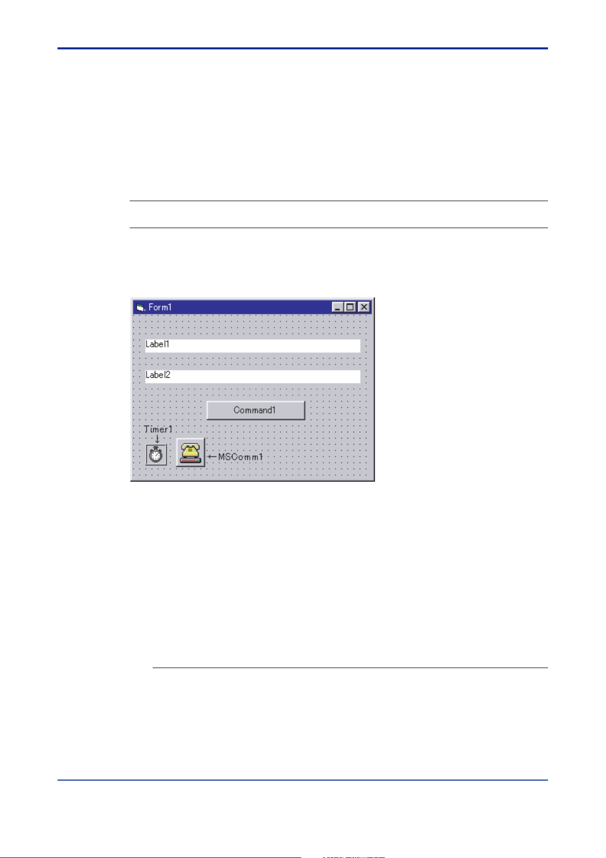
This subsection shows a sample program created using Microsoft Visual Basic 6.0.
Operation verification environment: PC/AT compatible machine + Windows NT 4.0
(SP4), Windows 95
PC/AT is a product of IBM Corporation.
Visual Basic is a registered trademark of Microsoft Corporation.
See Also
MSDN and commercially available documentation for information on Visual Basic programming.
The sample program reads the contents of D register D0002 using the PC link communication protocol. When you press the Command button, the commands sent and responses
received will be displayed in a form. If no response is received, a timeout will occur.
'==========================================================
' Program name: Sample
'
' RS-485 communication program for M series
'
'============================= YOKOGAWA Electric Corporation ===
'
'Definition of public variables
Public fSend As Boolean 'Sending flag
Public strSend As String 'Character string sent
Public strBuf1 As String 'Character (1 byte) received
Public strReceive As String 'Character string received
'When the Command button is pressed,
Private Sub Command1_Click()
strSend = "01010WRDD0002,01" 'Character string to be sent
'[stx]01010WRDD0002,01[etx][cr]
IM 77J04J11-01E 1st Edition : 2006.08.25-00
Page 36

<Toc> <Ind> <3. PC Link Communication >
Label1.Caption = "[stx]" + strSend + "[etx][cr]"
Label2.Caption = ""
MSComm1.PortOpen = True 'Open port
Timer1.Enabled = True 'Start timer for detecting timeout
Command1.Enabled = False 'Disable the Command button temporarily
fSend = True 'Set sending flag
'Send
MSComm1.Output = Chr(&H2) + strSend + Chr(&H3) + Chr(&HD)
'Send with stx, etx, and cr added
Do 'Loop until sending flag becomes false
If DoEvents() = 0 Then '
End If '
Loop Until fSend = False '
Timer1.Enabled = False 'Stop Timer 1
MSComm1.PortOpen = False 'Close port
3-22
Label2.Caption = strReceive 'Display received character string in Label 2
Command1.Enabled = True 'Enable the Command button
End Sub
--------------------------------------------------------------------------------
'At start of program
Private Sub Form_Load()
Form1.Caption = "Communication Sample"
'Set up timer for detecting timeout
Timer1.Enabled = False
Timer1.Interval = 2000
'Regard as being 2 seconds
'Initialize MSComm control
MSComm1.CommPort = 1 'COM1
MSComm1.InputLen = 1 'Size of receiving buffer
MSComm1.InputMode = comInputModeText 'Receiving mode
MSComm1.RThreshold = 1 'MSComm1_OnComm interrupt processing starts
'each time 1 byte is received
MSComm1.Settings = "9600,e,8,1" 'Communication conditions: 9600 bps; Parity,
'even; Data length, 8 bits; Stop bit, 1 bit
'Command button control
Command1.Caption = "Send"
IM 77J04J11-01E 1st Edition : 2006.08.25-00
Page 37

<Toc> <Ind> <3. PC Link Communication >
'Initialize label control that displays character strings sent and received
Label1.Caption = ""
Label2.Caption = ""
End Sub
--------------------------------------------------------------------------------
'This processing starts each time 1 byte is received
Private Sub MSComm1_OnComm()
Dim strBuf0 As String
Select Case MSComm1.CommEvent
Case comEvReceive
strBuf0 = MSComm1.Input '
Select Case strBuf0 'Case classification based on 1 byte received
Case Chr(2) 'When it is stx
strBuf1 = "[stx]"
Case Chr(3) 'When it is etx
strBuf1 = strBuf1 & "[etx]"
Case Chr(13) 'When it is cr
strBuf1 = strBuf1 & "[cr]"
'This is provided as a measure against the fact that a command sent may
'be seen as response depending on a combination with communication
'converter.
3-23
If strBuf1 = Label1.Caption Then
strBuf1 = ""
Else
strReceive = strBuf1 'Completion of character string received
fSend = False 'Receiving is regarded as being ended
End If
Case Else 'When it is not stx, etx, or cr
strBuf1 = strBuf1 & strBuf0
End Select
Case Else
End Select
End Sub
--------------------------------------------------------------------------------
'Timeout
Private Sub Timer1_Timer()
IM 77J04J11-01E 1st Edition : 2006.08.25-00
Page 38

<Toc> <Ind> <3. PC Link Communication >
strReceive = "Time Out!"
fSend = False 'Receiving is regarded as being ended
End Sub
3-24
IM 77J04J11-01E 1st Edition : 2006.08.25-00
Page 39

<Toc> <Ind> <3. PC Link Communication >
3.3.2 Communication with UT Link Module
Communication with FA-M3 is achieved by simply connecting the M Series to a UT
link module using the PC link communication protocol. Set the communication
conditions of the M Series identical to those of the UT link module.
Model of UT link module: F3LC51-2N
FA-M3
A maximum of 1200 m; up to 31 slave stations
The UT link module supports the following two types of communication modes and command communication, which allow you to communicate with FA-M3 without being aware of
it. For more information, see the optionally available "UT Link Module User's Manual (IM
34M6H25-01E)."
3-25
1. Automatic mode
This mode enables the instrument's fixed devices (those that cannot be specified by
the user) to be constantly refreshed by reading from them. The fixed devices are
D0001 to D0004. They are read-only areas and cannot be written into.
2. Manual mode
This mode enables the instrument's devices (those that can be specified by the user)
to be constantly refreshed by reading from and/or writing into them.
See Also
The devices mentioned here are D registers and I relays. For more information on D registers and I
relays, see Chapters 6 and 7.
3. Command communication
Command communication allows the user to communicate with instruments as and
when required.
IM 77J04J11-01E 1st Edition : 2006.08.25-00
Page 40

<Toc> <Ind> <3. PC Link Communication >
3.3.3 Communication with Touch Panel
Communication with a touch panel is achieved using the PC link communication
protocol. Set the communication conditions of the M Series identical to those of the
touch panel.
Graphic panel
A maximum of 1200 m; up to 31 slave stations
For more information, refer to the user's manual of the touch panel to be connected.
3-26
Model Name Remarks
Yokogawa TOP75T Touch operation panel (large) 10-inch
TOP72S
Digital’s
Pro-face
Note 1: For Digital's graphic panels, contact Digital Corp. directly.
Note 2: The system data area should be assigned to D0450.
*1: Display devices differ depending on the model.
GP70 Series Graphic operation panel
GP-J Series High-speed graphic operation panel
GP-230 Series Medium-size graphic operation panel
GP-430 Series High-speed, advanced graphic operation
GP-530 Series
Touch operation panel (medium) 5-inch
panels
TFT color LCD
STN color LCD
(*1)
IM 77J04J11-01E 1st Edition : 2006.08.25-00
Page 41

<Toc> <Ind> <4. Ladder Communication >
4. Ladder Communication
4.1 Overview
The use of Ladder communication enables the M Series to communicate with a
sequencer (PLC). By specifying the register numbers of D registers of the M Series
as parameters in the ladder program, you can read/write data from/into the registers
using BCD codes (0 to 9).
Ladder communication module
PLC
A maximum of 1200 m; up to 31 slave stations
4-1
Figure 4-1 Example of Connection for Ladder Communication
● Connecting the M Series to a PLC of another company
When the M Series are connected to a PLC manufactured by Mitsubishi Electric (MELSECA series), you can use the no-handshaking mode of the computer link unit.
IM 77J04J11-01E 1st Edition : 2006.08.25-00
Page 42

<Toc> <Ind> <4. Ladder Communication >
4.2 Commands/Responses at the PLC
The PLC sends commands and receives responses to these commands. The commands and responses that can be used are as follows.
4.2.1 Configuration of Command/Response
Commands sent from the PLC to the M Series and responses from the M Series with
respect to a command sent from the PLC consist of the following elements.
Number of Bytes 1 1 221111
Number of BCD Digits 2 2 1 4422111
Command/Response
element
(1) Address Number (01 to 99)
Address numbers are used by the PLC to identify the M Series at the communication
destination. (Identification numbers specific to individual M Series.)
Address
number
(ADR)
(1) (2) (3) (4) (5) (7) (8) (9)(6)
number
CPU
01
Parameter
number
0 R/W +/-0 Data
Can be changed only during a read operation.
A maximum of 64 data items
4-2
CR
(0D)LF(0A)
(2) CPU Number
This is fixed to 01.
(3) Parameter Number
This is 4-digit BCD data of a D register number with its leading character D removed.
I relays cannot be specified.
See Also
Chapter 6 for more information on D registers.
(4) 0
This is fixed to 0.
(5) 0
This is fixed to 0.
(6) R/W
0: Read
1: Write
(7) +/-
0: Positive data (+)
1: Negative data (-)
(8) Data
For read operation, this is the number of data items to be read.
For write operation, it is the setting data.
(9) CR and LF
These control codes indicate the end of a command. The corresponding control
character strings for CR and LF are 0D and 0A in hexadecimal in ASCII code, respectively.
IM 77J04J11-01E 1st Edition : 2006.08.25-00
Page 43

<Toc> <Ind> <4. Ladder Communication >
4.2.2 Reading Parameters
Shown below are the configurations of commands and responses when parameters in the
M Series are read by the PLC. (The maximum number of data items to be read is 64.)
● Command/Response
Number of Bytes 1 1 221111
Number of BCD Digits 2 2 1 4422111
Command element Address
number
(ADR)
number
CPU
01
Parameter
number
0000 Number of
read data
(n)
CR
(0D)LF(0A)
4-3
Number of Bytes 1 1 2
Number of BCD Digits 2 2 4
Parameter
Response element Address
number
(ADR)
CPU
number
01
• • •
• • •
number
Data of parameter number (n)
● Example:
Reading the input value (D0003) of the M Series with address number 01.
[Command]
01010003000000010D0A
The input value 500 (BCD code) is returned with respect to the above command (50.0 is
expressed as 500).
211
14111
00+/-0 dddd1
Data of parameter number (a) Data of parameter number (b)
21111
1422111
00+/-0 ddddn
CR
(0D)LF(0A)
14111
00+/-0 dddd2
211
[Response]
01010003000005000D0A
IM 77J04J11-01E 1st Edition : 2006.08.25-00
Page 44

<Toc> <Ind> <4. Ladder Communication >
4.2.3 Writing Parameters
Shown below are the configurations of commands and responses when the parameters
are written into the M Series from the PLC.
● Command/Response
Number of Bytes 1 1 221111
Number of BCD Digits 2 2 1 4422111
Command element Address
Number of Bytes 1 1 221111
Number of BCD Digits 2 2 1 4422111
Response element Address
number
(ADR)
number
(ADR)
number
number
● Example:
CPU
01
CPU
01
Parameter
number
Parameter
number
01+/-0 dddd
01+/-0 dddd
4-4
CR
(0D)LF(0A)
CR
(0D)LF(0A)
Writing 200 into the alarm-1 setpoint (D0101) of the M Series with address number 01.
[Command]
01010101001002000D0A
The alarm-1 setpoint 200 (BCD code) is returned with respect to the above command (20.0
is expressed as 200).
[Response]
01010101001002000D0A
IM 77J04J11-01E 1st Edition : 2006.08.25-00
Page 45

<Toc> <Ind> <4. Ladder Communication >
4.2.4 Response Error Codes
Data that the master station (PLC) will receive in the event of an error and the description of
errors are given in the table below.
0101/0103/0000/0001/CR/LF
Read/write data
0, 0, R/W, and +/-
Parameter number
Address number and CPU number
Note: Slashes (/) in the following send and receive data examples are used for explanatory purposes only, and are not part of
the actual data string.
Table 4-2 List of Error Codes
4-5
Description of Error
A non-existent parameter was set. 0101/0451/0000/0001/CR/LF 0101/0451/0000/FFFF/CR/LF
were used other than in an address number.
* This excludes LF (0A).
an address number.
An address differed from the address
numbers of the M Series.
* In the example at right, none of the address numbers exist.
data) is incorrect.
* The command length, including CR and LF, must be 10 bytes.
* Timeout is 2 seconds.
The buffer overflowed.
* This error occurs when the buffer overflow exceeds 368 bytes.
Example of Data Sent
by Master Station
0101/0420/0000/000B/CR/LF
0101/0420/000B/0000/CR/LF
0101/0420/0B00/0000/CR/LF
0101/042B/0000/0000/CR/LF
0101/0420/0000/000A/CR/LF
0101/0420/000A/0000/CR/LF
0101/0420/0A00/0000/CR/LF
0101/040A/0000/0000/CR/LF
0103/0420/0000/0000/CR/LF
0001/0420/0000/0000/CR/LF
3301/0420/0000/0000/CR/LF
0101/0420/0000/00/CR/LF
0101/0420/0/CR/LF
0101/0/CR/LF
0101/012 No responseA timeout occurred during communication.
–
–A framing error or a parity error occurred. No response
0101/FFFF/FFFF/FFFF/CR/LFCharacters other than a BCD code (0 to 9)
No responseAn LF code (0A) was used other than in
No response
No responseThe command length (length of the send
No response
Data Received
by Master Station
FFFF is returned.
CAUTION
If a parameter not existing in the D register table is read, an error will not occur. In this
case, 0 will be returned instead.
IM 77J04J11-01E 1st Edition : 2006.08.25-00
Page 46

Blank Page
Page 47

<Toc> <Ind> <5. MODBUS Communication >
5. MODBUS Communication
5.1 Overview
The use of MODBUS communication enables the M Series to communicate with a
PC. In this communication, you can use a PC to read/write data from/into D registers,
which are internal registers of the M Series.
PC
A maximum of 1200 m; up to 31 slave stations
5-1
Figure 5-1 Example of Connection for MODBUS Communication
Hereafter, PCs are generically called "higher-level devices."
See Also
Chapter 6 for information on the D registers.
For the MODBUS communication of the M Series, two transmission modes are supported:
ASCII mode and RTU mode (binary system).
Table 5-1 ASCII and RTU Modes
Item ASCII Mode RTU Mode
Number of data bits 7 bits (ASCII) 8 bits (binary)
Message start mark
Message end mark
Message length (*1)
Data time intervals 1 second or less 24 bit time or less (*2)
Error detection
*1: When the message length in the RTU mode is assumed to be "N."
*2: When the baud rate is 9600 bps, 1⫼9600⫻24 seconds or less applies.
: (colon) Not necessary
CR+LF Not necessary
2N+1 N
Longitudinal redundancy check: LRC Cyclic redundancy check: CRC-16
In MODBUS communication, a higher-level device identifies each M Series with an address number, which ranges from 01 to 99.
IM 77J04J11-01E 1st Edition : 2006.08.25-00
Page 48

<Toc> <Ind> <5. MODBUS Communication >
5.1.1 Configuration of Message
Messages sent from a higher-level device to the M Series consist of the following elements.
5-2
Element Address
Number of bytes in RTU mode None
Number of bytes in ASCII mode 2 2
Message Mark
None
1224n
(1) (3) (4) (5)(2) (6)
Number
(ADR)
1 1 2n 2
Function CodeStart of
Data Error Check End of
Message Mark
(1) Start of Message Mark
This mark indicates the start of a message. Note that only ASCII mode requires a
colon (:).
(2) Address Number (01 to 99)
Address numbers are used by a higher-level device to identify the M Series at the
communication destination. (Identification numbers specific to individual M Series,
which is expressed in hexadecimal in the message.)
(3) Function Code (See subsection 5.2.1, "List of Function Codes.")
This specifies a command (function code) from the higher-level device.
(4) Data
This specifies D register numbers, the number of D registers, parameter values, or
others in accordance with the function code. (It is expressed in hexadecimal in the
message.)
(5) Error Check
In RTU mode : Carried out by the cyclic redundancy check (CRC-16) system.
In ASCII mode : Carried out by the longitudinal redundancy check (LRC) system.
(6) End of Message Mark
This mark indicates the end of a message. Note that only ASCII mode requires CR +
LF.
IM 77J04J11-01E 1st Edition : 2006.08.25-00
Page 49

<Toc> <Ind> <5. MODBUS Communication >
5.1.2 Specifying D Registers
When you use a commercially available SCADA or the like or a user-created communication program, you must be careful when specifying D register numbers contained in messages because in both cases, you cannot use the original D register numbers as they are.
1) When using a commercially available SCADA or the like, specify D register numbers
by changing them into reference numbers. To change them into a reference number,
replace the D register number's leading character "D" with "4."
2) In a user-created communication program, specify a D register using the hexadecimal
number of the value obtained by subtracting "40001" from the D register's reference
number. (Specify this hexadecimal number.)
Example:
Specifying a value (alarm-1 setpoint [D0101])
1) For a messages using commercially available SCADA or the like, specify reference
number "40101."
2) For a messages in a user-created communication program, specify "0064," the
hexadecimal number of "100 ," which is obtained by subtracting 40001 from the
reference number.
5-3
IM 77J04J11-01E 1st Edition : 2006.08.25-00
Page 50

<Toc> <Ind> <5. MODBUS Communication >
5.2 Function Codes
5.2.1 List of Function Codes
Function codes are command words used by the higher-level device to obtain the D register data of the M Series.
Table 5-2 List of Function Codes
5-4
Code Number
03 Reads data from multiple
06 Writes data into a register. Capable of writing data into one register.
16 Capable of writing data into a maximum of 64 successive
registers.
Performs loop back test.08 Used to check the connection for communication.
Writes data into multiple
registers.
Function Description
Capable of reading data from a maximum of 64 successive
registers.
registers.
• The write function codes will not write into read-only or disabled registers.
• Broadcast addressing is possible with function codes 06 and 16 only. (Also in this
case, read-only or disabled registers will not be written into.)
IM 77J04J11-01E 1st Edition : 2006.08.25-00
Page 51

<Toc> <Ind> <5. MODBUS Communication >
03 Reads data from multiple D registers
● Function
Reads the contents of a sequence of contiguous D registers by the specified number of D
registers, starting at a specified D register number.
• The maximum number of D registers to be read at a time is 64.
• For the format of response in the event of failure, see subsection 5.2.2.
● Message (for normal operation)
5-5
Element Start of
Number of bytes in RTU mode
Number of bytes in ASCII mode
Message (continued)
Error
Check
End of Message
Mark (CR+LF)
2
22
None
Address
Message Mark
(:)
None 1 1 2
Number
(ADR)
Function
Code (03)
D-Register
Start Number
4122
● Response (for normal operation)
Element Start of
Number of bytes in RTU mode None 1 1 1 2
Response (continued)
• • •
• • •
• • •
Contents of
D Register
Message Mark
Error
Check
(:)
12 224Number of bytes in ASCII mode
End of Message
Mark (CR+LF)
None22
Address
Number
(ADR)
224
Function
Code (03)
Byte
Count
Number of
D Registers
2
4
Contents of
D Register
IM 77J04J11-01E 1st Edition : 2006.08.25-00
Page 52

<Toc> <Ind> <5. MODBUS Communication >
● Example:
Reading the statuses of alarm-1 and alarm-2 setpoints of the M Series with address number 01.
The following message reads two successive D registers starting at alarm-1 setpoint
(D0101) of address number 01 in the ASCII mode.
[Message]
: 01030064000296[CR][LF]
Start of message mark
"01": address number 01, "03": function code 03, "0064": D-register start number 0101,
"0002": number of D registers 2, and "96": error check
Note: The numbers in quotation marks are hexadecimal.
The following response is returned with respect to the above message.
[Response]
: 01030400010000F7[CR][LF]
Alarm-1 setpoint is 1. Alarm-2 setpoint is 0.
5-6
IM 77J04J11-01E 1st Edition : 2006.08.25-00
Page 53

<Toc> <Ind> <5. MODBUS Communication >
06 Writes data into a D register
● Function
Writes data into a specified D register.
• The maximum number of D registers to be written into at a time is 1.
• For the format of response in the event of failure, see subsection 5.2.2.
• Broadcast addressing is possible by setting 00 in the address number.
● Message (for normal operation)
5-7
Element Start of
Number of bytes in RTU mode None 1 1 1
Message (continued)
Write Data
(Upper Digit)
1
2
Write Data
(Lower Digit)
1
2
Message Mark
(:)
1
Error
Check
2
2
Address
Number
(ADR)
22 2
End of Message
Mark (CR+LF)
None
2
Function
Code (06)
D-Register
Number
(Upper Digit)
1
2Number of bytes in ASCII mode
● Response (for normal operation)
Element Start of
Number of bytes in RTU mode None 1 1 1
Response (continued)
Write Data
(Upper Digit)
Write Data
(Lower Digit)
Message Mark
(:)
1
Error
Check
Address
Number
(ADR)
22 2
End of Message
Mark (CR+LF)
Function
Code (06)
D-Register
Number
(Upper Digit)
1
2Number of bytes in ASCII mode
D-Register
Number
(Lower Digit)
D-Register
Number
(Lower Digit)
1
2
1
2
2
2
None
2
IM 77J04J11-01E 1st Edition : 2006.08.25-00
Page 54

<Toc> <Ind> <5. MODBUS Communication >
● Example:
Setting 70.00 into the alarms-1 setpoint of the M Series with address number 01.
The following message writes 70.00 into the alarms-1 setpoint (D0101) of address number
01 in the ASCII mode.
[Message]
: 010600641B5822[CR][LF]
Start of message mark
"01": address number 01, "06": function code 06, "0064": D-register number 0101,
"1B58": data 70.00, and "22": error check
Note: The numbers in quotation marks are hexadecimal.
The following response is returned with respect to the above message.
[Response]
: 010600641B5822[CR][LF]
Alarm-1 setpoint is 70.00.
5-8
IM 77J04J11-01E 1st Edition : 2006.08.25-00
Page 55

<Toc> <Ind> <5. MODBUS Communication >
08 Performs loop back test
● Function
This function code is used to check the connection for communication.
• For the format of response in the event of failure, see subsection 5.2.2.
• The element marked with * is "00" (fixed).
• Any value can be selected for send data.
● Message (for normal operation)
5-9
Element Function
Number of bytes in RTU mode
Number of bytes in ASCII mode
Message (continued)
Error
Check
End of Message
Mark (CR+LF)
None2
22
Start of
Message Mark
(:)
● Response (for normal operation)
Element Function
Number of bytes in RTU mode
Number of bytes in ASCII mode
Response (continued)
Error
Check
End of Message
Mark (CR+LF)
None2
22
Start of
Message Mark
(:)
Address
Number
(ADR)
Address
Number
(ADR)
Code (08)
Code (08)
00*
0000
211None
4221
00
0000
211None
4221
Send Data
(any)
2
4
Same as
send data
2
4
● Example:
Sending data 1234 (HEX) to the M Series with address number 01 to check connection for
communication.
The following message sends 1234 (HEX) to address number 01 in the ASCII mode.
[Message]
: 010800001234B1[CR][LF]
Start of message mark
When the connection for communication is normal, the response whose configuration is the
same as that of the message is returned with respect to the above message.
[Response]
: 010800001234B1[CR][LF]
IM 77J04J11-01E 1st Edition : 2006.08.25-00
Page 56

<Toc> <Ind> <5. MODBUS Communication >
16 Writes data into multiple D registers
● Function
Writes data into a sequence of contiguous D registers by the specified number of D registers, starting at a specified D register number.
• The maximum number of D registers to be written into at a time is 32.
• For the format of response in the event of failure, see subsection 5.2.2.
• Broadcast addressing is possible by setting 00 in the address number.
● Message (for normal operation)
5-10
Element Start of
Number of bytes in RTU mode None 1 1 1
Message (continued)
Number of
D Registers
(Upper Digit)
1
2
Number of
D Registers
(Lower Digit)
1
2
Message Mark
(:)
1
Byte
Count
(Upper Digit)
1
2
Data
Address
Number
(ADR)
22 2
(Lower Digit)
1
2
Function
Code (10)
Data
1
2
• • •
• • •
• • •
D-Register
Start Number
(Upper Digit)
1
2Number of bytes in ASCII mode
Error
Check
2
2
● Response (for normal operation)
Element Start of
Number of bytes in RTU mode None 1 1 1
Response (continued)
Number of
D Registers
(Upper Digit)
1
2
Number of
D Registers
(Lower Digit)
1
2
Message Mark
(:)
1
Error
Check
End of Message
Mark (CR+LF)
2
2
Address
Number
(ADR)
22 2
None
2
Function
Code (10)
D-Register
Start Number
(Upper Digit)
1
2Number of bytes in ASCII mode
D-Register
Start Number
(Lower Digit)
End of Message
Mark (CR+LF)
None
2
D-Register
Start Number
(Lower Digit)
IM 77J04J11-01E 1st Edition : 2006.08.25-00
Page 57

<Toc> <Ind> <5. MODBUS Communication >
● Example:
Setting 200, 10 and 3 into the alarms-1 setpoint, alarm-2 setpoint and alarm-3 setpoint of
the M Series with address number 02, respectively.
The following message writes 200, 10 and 3 in this order in the ASCII mode, starting at the
alarm-1 setpoint (D0101) of address number 02 .
[Message]
: 0210006400030600C8000A0003AC[CR][LF]
Start of message mark
"02": address number 02, "10": function code 16, "0064": D-register start number 0101,
"0003": number of D registers 3, "06": byte count, "00C8": alarm-1 setpoint 200,
"000A": alarm-2 setpoint 10, "0003": alarm-3 setpoint 3, and "AC": error check
Note: The numbers in quotation marks are hexadecimal.
The following response is returned with respect to the above message.
[Response]
: 02100064000387[CR][LF]
The number of registers is 3.
5-11
IM 77J04J11-01E 1st Edition : 2006.08.25-00
Page 58

<Toc> <Ind> <5. MODBUS Communication >
5.2.2 Response Error Codes
● Message Format in the Event of Error
If there are any inconsistencies other than communication errors in a message, the M
Series does nothing, but returns the following message.
5-12
Element Function Code
Number of bytes in RTU mode
Number of bytes in ASCII mode 2
*1: In this case, a value of [function code (hexadecimal number) + number 80 (hexadecimal number)] is set.
Address
Number
(ADR)
1
2
(*1)
1
2
Error Code Error Check [CR] [LF]
1
2
● Response Error Codes
Table 5-3 List of Error Codes
Error Code Meaning Cause
01
02 D-register number error
03 D-register count error
Function code error
No such function code exists.
Specified D register number is out of the range.
Specified number of D registers is out of the range.
● Even when a message is sent, no response returns if:
• Retransmission error (overrun, framing, parity, LRC, or CRC-16 error) was detected.
• Address in a command message is incorrect.
• Interval between data composing a message was 2 seconds or more.
2
None
2
• CRC-16 or LRC values are incorrect.
• Broadcase is specified (address number: 00).
Note: As a countermeasure, provide a timeout process in the communication functions of a higher-level device or in the
communication program.
IM 77J04J11-01E 1st Edition : 2006.08.25-00
Page 59

<Toc> <Ind> <5. MODBUS Communication >
5.2.3 Specifying Broadcast
Broadcast addressing allows the corresponding multiple M Series to receive the command.
(1) To use this function, specify 00 in the address number.
(2) Broadcast addressing works independently of the address number.
(3) Broadcast addressing is only applicable to write commands.
(4) No response is returned if broadcast addressing is used.
Higher-level device (master)
Broadcast data.
* No response from slaves
A maximum of 1200 m; up to 31 slave stations
5-13
For the M Series communication, D registers are used.
IM 77J04J11-01E 1st Edition : 2006.08.25-00
Page 60

Blank Page
Page 61

<Toc> <Ind> <6. Functions and Usage of D Registers >
6. Functions and Usage of D Registers
6.1 Overview of D Registers
This section describes the functions and usage of D registers.
The D registers store the input and output values, statuses and others that are
handled by the M Series. By connecting M Series to higher-level device capable of
PC link communication, Ladder communication or MODBUS communication, you
can readily use these internal data items by reading from or writing into the D registers.
6.2 Interpretation of D Register Map Table
This section explains how to read D Register Map tables in this chapter. The numbers listed in the leftmost column are D register numbers ((1) below). The five-digit
numbers in the next column are reference numbers used for MODBUS communication ((2) below). The numbers in the column third from left are register numbers in
hexadecimal used in MODBUS communication programs ((3) below).
6-1
D-Register Data Area
D-Reg No. Ref No. H No. Description R/W
D0001 40001 0000
(1) D register number
(2) Reference number (for MODBUS communication)
(3) Hex number (for MODBUS communication)
Status R
Permission of read/write by communication
: Indicates that the number of writing
actions is limited to 100,000.
IM 77J04J11-01E 1st Edition : 2006.08.25-00
Page 62

<Toc> <Ind> <6. Functions and Usage of D Registers >
6.3 D Register Map Table
D-Register Data Area
D-Reg No.
D0001
D0002
D0003
D0004
D0005 to D0100
D0101
D0102
D0103
D0104
D0105
D0106
D0107
D0108
D0109
D0110
D0 111
D0112
D0113
D0114
D0115
D0116
D0117 to D0200
D0201
D0202
D0203
D0204
D0205
D0206 to D0209
D0210
D0211
D0212
D0213
D0214
D0215
D0216 to D0300
D0301
D0302
D0303
D0304
D0305
D0306
D0307 to D0308
D0309
D0310
D0311
D0312
D0313 to D0400
D0401 to D0450
*1: User area applies when a graphic panel manufactured by Digital Corp. is used.
Ref No.
40001
40002
40003
40004
40101
40102
40103
40104
40105
40106
40107
40108
40109
40110
40 111
40112
40113
40114
40115
40116
40201
40202
40203
40204
40205
40210
40211
40212
40213
40214
40215
40301
40302
40303
40304
40305
40306
40309
40310
40311
40312
40401 to 40450
: The number of writing actions is limited to 100,000.
H No.
0000
0001
0002
0003
0064
0065
0066
0067
0068
0069
006A
006B
006C
006D
006E
006F
0070
0071
0072
0073
00C8
00C9
00CA
00CB
00CC
00D1
00D2
00D3
00D4
00D5
00D6
012C
012D
012E
012F
0130
0131
0134
0135
0136
0137
0190 to 01C1
Status
Alarm status
Input value (display value)
Input unit
Alarm-1 setpoint (A1)
Alarm-2 setpoint (A2)
Alarm-3 setpoint (A3)
Alarm-4 setpoint (A4)
Alarm-1 action (AL1)
Alarm-2 action (AL2)
Alarm-3 action (AL3)
Alarm-4 action (AL4)
Alarm-1 hysteresis (HY1)
Alarm-2 hysteresis (HY2)
Alarm-3 hysteresis (HY3)
Alarm-4 hysteresis (HY4)
Alarm ON delay (OND)
Alarm OFF delay (OFD)
Setpoint (SP)
Keylock (LOC)
Bias (BS)
Economical mode (ECO)
Burnout action (BSL)
Wiring resistance correction (WIR)
RJC sensor (RJC)
Communication protocol (PSL)
Address number (ADR)
Baud rate (BPS)
Parity (PRI)
Stop bit (STP)
Data length (DLN)
Range code number (IN)
Maximum measured input value (RH)
Minimum measrued input value (RL)
Decimal point position of scaling value (SDP)
Maximum scaling value (SH)
Minimum scaling value (SL)
Input adjustment point LOW (BL)
Input adjustment LOW (AL)
Input adjustment point HIGH (BH)
Input adjustment HIGH (AH)
User area *1
Description
6-2
R/W
R
R
R
R
R/W
R/W
R/W
R/W
R/W
R/W
R/W
R/W
R/W
R/W
R/W
R/W
R/W
R/W
R/W
R/W
R/W
R/W
R/W
R
R/W
R/W
R/W
R/W
R/W
R/W
R/W
R/W
R/W
R/W
R/W
R/W
R/W
R
R
R
R
R/W
IM 77J04J11-01E 1st Edition : 2006.08.25-00
Page 63

<Toc> <Ind> <6. Functions and Usage of D Registers >
6.3.1 Contents of D Registers
● D0001: Bit configuration of status
The D0001 register represents errors and parameter data by a combination of bits in the
register.
In the table below, if any of the events shown occurs, the corresponding bit is set to "1."
The bit remains set to "0" if the event has not occurred yet. Note that blank fields indicate
bits not used, which are in "0."
Bit Description
0 Alarm-1 status
1 Alarm-2 status
2
3
4 Input exceeding high limit
5 Input falling below low limit
6 Burnout
7
8
9 EEP sum error
10 Parameter error
11
12
13 RJC error
14 EEP error
15
6-3
● D0002: Bit configuration of alarm status
Bit Description
0 Alarm-1 status
1 Alarm-2 status
2
3
4 Alarm-3 status
5 Alarm-4 status
6 to 15
IM 77J04J11-01E 1st Edition : 2006.08.25-00
Page 64

<Toc> <Ind> <6. Functions and Usage of D Registers >
● D0003: INPUT (Input value: display value)
● D0004: IN UNIT (Input unit)
UnitD0004 value Model
H'0000
H'0003
H'0004
No unit
degC
K
MVHK
MVTK, MVRK
MVTK, MVRK
6-4
IM 77J04J11-01E 1st Edition : 2006.08.25-00
Page 65

<Toc> <Ind> <7. Functions and Usage of I Relays >
7. Functions and Usage of I Relays
This chapter describes the functions and usage of the I relays.
The I relays store information on errors, alarm statuses and others of the M Series.
The higher-level device can read data from I relays or write data into I relays using
PC link communication.
7-1
IM 77J04J11-01E 1st Edition : 2006.08.25-00
Page 66

<Toc> <Ind> <7. Functions and Usage of I Relays >
7.1 Status
The following table shows how the I relays are classified.
I-Relay No. Type of Status Description
1 to 16 Error information (same contents as those of D0001)
17 to 32
33 to 64
CAUTION
• The I relays numbered 1 to 32 store ON/OFF statuses. Generally, this area can be
accessed to read the ON/OFF statuses.
• When specifying an I relay number via communication, begin the number with an
upper-case letter I. For example, type I0001 to specify the alarm-1 status (I relay
number: 1).
• No data may be written into or read from data storage areas with blank fields in the
table below. If you attempt to do so, the M Series may fail to operate normally.
ON/OFF
Alarm status (same contents as those of D0002)
User area (that is used in some devices such as
graphic panels)
7-2
I-Relay No.
1
2
3
4
5
6
7
8
9
10
11
12
13
14
15
16
17
18
19
20
21
22
23 to 32
33 to 64
I-Relay Area
Description
Alarm-1 status
Alarm-2 status
Input exceeding high limit
Input falling below low limit
Burnout
EEP sum error
Parameter error
RJC error
EEP error
Alarm-1 status
Alarm-2 status
Alarm-3 status
Alarm-4 status
User area
IM 77J04J11-01E 1st Edition : 2006.08.25-00
Page 67

<Toc> <Ind> <Appendix. Table of ASCII Codes (Alphanumeric Codes) >
Appendix Table of ASCII Codes
(Alphanumeric Codes)
In order to implement PC link communication, create a transmission/receiving
program by referring to the Table of ASCII Codes below.
0
0
0
0
0
0
0
0
0
1
2
3
4
5
6
7
8
9
A
B
C
D
E
F
0
NUL DLE
SOH DC1
STX DC2
ETX DC3
EOT DC4
ENQ NAK
ACK SYN
BEL ETB
CAN
BS
HT
SUB
LF
ESC
VT
FF
CR
SO
SI
b1
b2
b3
b4
b5b6b7b8
0
0
0
0
1
0
0
0
0
1
0
0
1
1
0
0
0
0
1
0
1
0
1
0
0
1
1
0
1
1
1
0
0
0
0
1
1
0
0
1
0
1
0
1
1
1
0
1
0
0
1
1
1
0
1
1
0
1
1
1
1
1
1
1
0
0
1
1
EM
FS
GS
RS
US
0
1
0
2
SP
!
“
#
$
%
&
‘
(
)
*
+
,
-
.
/
1
0
0
1
0
1
4
3
@
0
A
1
B
2
C
3
D
4
E
5
F
6
G
7
H
8
I
9
J
:
K
;
L
<
M
=
N
>
O
?
0
1
0
1
5
P
Q
R
S
T
U
V
W
X
Y
Z
[
\
]
•
_
App.-1
0
0
1
1
1
1
1
0
7
6
p
`
q
a
r
b
s
c
t
d
u
e
v
f
w
g
x
h
y
i
z
j
{
k
l
}
m
~
n
DEL
o
Note: SP($20): space
DEL($7F): control code
Control code Character code
IM 77J04J11-01E 1st Edition : 2006.08.25-00
Page 68

Blank Page
Page 69

<Int> <Toc> <Ind>
Revision Information
● Title : M Series Digital Limit Alarms Communication Functions
● Manual No. : IM 77J04J11-01E
Aug. 2006/1st Edition
Newly published
i
Written by Yokogawa Electric Corporation
Published by Yokogawa Electric Corporation
2-9-32 Nakacho, Musashino-shi, Tokyo 180-8750, JAPAN
IM 77J04J11-01E 1st Edition : 2006.08.25-00
Page 70

Blank Page
 Loading...